WO2022181592A1 - 異種金属材の接合方法 - Google Patents
異種金属材の接合方法 Download PDFInfo
- Publication number
- WO2022181592A1 WO2022181592A1 PCT/JP2022/007173 JP2022007173W WO2022181592A1 WO 2022181592 A1 WO2022181592 A1 WO 2022181592A1 JP 2022007173 W JP2022007173 W JP 2022007173W WO 2022181592 A1 WO2022181592 A1 WO 2022181592A1
- Authority
- WO
- WIPO (PCT)
- Prior art keywords
- electrode
- rivet
- electrical resistance
- resistance value
- metal members
- Prior art date
- Legal status (The legal status is an assumption and is not a legal conclusion. Google has not performed a legal analysis and makes no representation as to the accuracy of the status listed.)
- Ceased
Links
Images


Classifications
-
- B—PERFORMING OPERATIONS; TRANSPORTING
- B23—MACHINE TOOLS; METAL-WORKING NOT OTHERWISE PROVIDED FOR
- B23K—SOLDERING OR UNSOLDERING; WELDING; CLADDING OR PLATING BY SOLDERING OR WELDING; CUTTING BY APPLYING HEAT LOCALLY, e.g. FLAME CUTTING; WORKING BY LASER BEAM
- B23K11/00—Resistance welding; Severing by resistance heating
- B23K11/16—Resistance welding; Severing by resistance heating taking account of the properties of the material to be welded
- B23K11/20—Resistance welding; Severing by resistance heating taking account of the properties of the material to be welded of different metals
-
- B—PERFORMING OPERATIONS; TRANSPORTING
- B23—MACHINE TOOLS; METAL-WORKING NOT OTHERWISE PROVIDED FOR
- B23K—SOLDERING OR UNSOLDERING; WELDING; CLADDING OR PLATING BY SOLDERING OR WELDING; CUTTING BY APPLYING HEAT LOCALLY, e.g. FLAME CUTTING; WORKING BY LASER BEAM
- B23K11/00—Resistance welding; Severing by resistance heating
- B23K11/002—Resistance welding; Severing by resistance heating specially adapted for particular articles or work
- B23K11/004—Welding of a small piece to a large or broad piece
- B23K11/0066—Riveting
-
- B—PERFORMING OPERATIONS; TRANSPORTING
- B23—MACHINE TOOLS; METAL-WORKING NOT OTHERWISE PROVIDED FOR
- B23K—SOLDERING OR UNSOLDERING; WELDING; CLADDING OR PLATING BY SOLDERING OR WELDING; CUTTING BY APPLYING HEAT LOCALLY, e.g. FLAME CUTTING; WORKING BY LASER BEAM
- B23K11/00—Resistance welding; Severing by resistance heating
- B23K11/10—Spot welding; Stitch welding
- B23K11/11—Spot welding
- B23K11/115—Spot welding by means of two electrodes placed opposite one another on both sides of the welded parts
-
- B—PERFORMING OPERATIONS; TRANSPORTING
- B23—MACHINE TOOLS; METAL-WORKING NOT OTHERWISE PROVIDED FOR
- B23K—SOLDERING OR UNSOLDERING; WELDING; CLADDING OR PLATING BY SOLDERING OR WELDING; CUTTING BY APPLYING HEAT LOCALLY, e.g. FLAME CUTTING; WORKING BY LASER BEAM
- B23K35/00—Rods, electrodes, materials, or media, for use in soldering, welding, or cutting
- B23K35/22—Rods, electrodes, materials, or media, for use in soldering, welding, or cutting characterised by the composition or nature of the material
- B23K35/24—Selection of soldering or welding materials proper
- B23K35/30—Selection of soldering or welding materials proper with the principal constituent melting at less than 1550°C
- B23K35/302—Cu as the principal constituent
-
- B—PERFORMING OPERATIONS; TRANSPORTING
- B23—MACHINE TOOLS; METAL-WORKING NOT OTHERWISE PROVIDED FOR
- B23K—SOLDERING OR UNSOLDERING; WELDING; CLADDING OR PLATING BY SOLDERING OR WELDING; CUTTING BY APPLYING HEAT LOCALLY, e.g. FLAME CUTTING; WORKING BY LASER BEAM
- B23K11/00—Resistance welding; Severing by resistance heating
- B23K11/24—Electric supply or control circuits therefor
-
- B—PERFORMING OPERATIONS; TRANSPORTING
- B23—MACHINE TOOLS; METAL-WORKING NOT OTHERWISE PROVIDED FOR
- B23K—SOLDERING OR UNSOLDERING; WELDING; CLADDING OR PLATING BY SOLDERING OR WELDING; CUTTING BY APPLYING HEAT LOCALLY, e.g. FLAME CUTTING; WORKING BY LASER BEAM
- B23K2103/00—Materials to be soldered, welded or cut
- B23K2103/18—Dissimilar materials
Definitions
- the present disclosure relates to a method for joining dissimilar metal materials using rivets to join a plurality of metal members made of different materials by resistance welding.
- a resistance welding method in which dissimilar metal materials are joined by resistance welding using a metal rivet having a head portion and a shaft portion.
- a resistance welding method for example, a rivet, an aluminum plate and an iron plate are sandwiched between two electrodes so that the head part, the shaft part, the aluminum plate and the iron plate are arranged in this order, and the aluminum plate is separated by applying pressure and electricity to these electrodes.
- a nugget is generated between the penetrating shaft and the iron plate, and the aluminum plate and the iron plate are joined by sandwiching the aluminum plate between the head and the iron plate.
- the electrode has an electrode portion and a shank that conducts electricity to the electrode portion and holds the electrode portion.
- a method for joining dissimilar metal materials is provided.
- This method for joining dissimilar metal materials is a method for joining a plurality of metal members made of different materials by resistance welding using a rivet. and an electrode portion provided at the tip of the shank; a sandwiching step of sandwiching the rivet and the plurality of metal members between the first electrode and the second electrode; and the first electrode and an embedding step of embedding the rivet in the metal member by pressurizing and energizing the second electrode, wherein the preparing step includes the first electrode and the second electrode, Two conditions satisfying the condition that the electrical resistance value of the first electrode and the electrical resistance value of the second electrode are equal to or less than the sum of the electrical resistance values of the plurality of metal members to be joined and the electrical resistance value of the rivet.
- the step of providing an electrode is included.
- FIG. 1 is a process chart showing a method for joining dissimilar metal materials as a first embodiment of the present disclosure
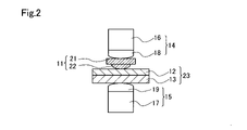
- FIG. FIG. 4 is a cross-sectional view schematically showing how a sandwiching step is implemented
- FIG. 2 is a diagram schematically explaining an example of an energization pattern in a method for joining dissimilar metal materials
- FIG. 1 is a process diagram showing a method for joining dissimilar metal materials as a first embodiment of the present disclosure.
- FIG. 2 is a cross-sectional view schematically showing the state of implementation of the sandwiching step, which will be described later.
- FIG. 2 shows a cross section passing through the central axis of each member.
- a plurality of (two in this embodiment) metal members made of different materials are joined by resistance welding using rivets 11 .
- an iron plate 13 and an aluminum plate 12 are joined as a plurality of metal members.
- the method for joining dissimilar metal materials comprises, as shown in FIG. 1, a preparation process P10, a sandwiching process P20, and an embedding process P30. Each step will be described below in order.
- the preparation step P10 the rivet 11, the aluminum plate 12, the iron plate 13, the first electrode 14, and the second electrode 15 are prepared.
- the first electrode 14 and the second electrode 15 are a pair of electrodes provided in a well-known resistance spot welder (not shown).
- the resistance spot welder is composed of a pressurization energizing section, a power supply section, a power control section, a cable for connection, and the like, which are not shown.
- Each of the electrodes 14, 15 is made of a copper alloy containing chromium (hereinafter referred to as "Cr-copper"). That is, both the shanks 16, 17 and the electrode portions 18, 19 are made of chromium copper.
- the electrodes 14 and 15 may be of an "integral type” in which the shanks 16 and 17 and the electrode sections 18 and 19 are integrated, or may be of a "cap type” in which the electrode sections 18 and 19 are replaceable. ' may be
- the rivet 11 is made of iron and has a head portion 21 and a shaft portion 22.
- the head 21 has a disc shape.
- the shaft portion 22 is formed in a substantially columnar shape and protrudes to one side from the central portion of the head portion 21 .
- the diameter of the shaft portion 22 gradually decreases toward the tip on the projecting side.
- the electrical resistance value R1 of the first electrode 14 and the electrical resistance value R2 of the second electrode 15 are both about 0.1 m ⁇ .
- the electrical resistance values R1 and R2 of the electrodes 14 and 15 are the sum of the electrical resistance values of the shanks 16 and 17 and the electrical resistance values of the electrode portions 18 and 19, respectively.
- the electrical resistance value R3 of the rivet 11 is approximately 0.15 m ⁇ .
- the electric resistance value R4 of the laminate to be welded 23 in which the aluminum plate 12 and the iron plate 13 are laminated is about 0.08 m ⁇ .
- the electrical resistance value is measured, for example, by a well-known resistance measuring instrument (not shown).
- the electrical resistance value R4 of the laminate to be welded 23 is measured by applying one terminal and the other terminal of a resistance measuring device so that their positions match in the direction of current flow.
- the electrical resistance value R3 of the rivet 11 is measured by applying one terminal to a portion to be contacted with the electrode portion 18 and applying the other terminal to a portion to be contacted to the aluminum plate 12 .
- the electrical resistance values R1 and R2 of the electrodes 14 and 15 are equal to or less than the total value of the electrical resistance value R3 of the rivet 11 and the electrical resistance value R4 of the laminate 23 to be welded. That is, it satisfies the relationship of the following formulas (i) and (ii). That is, in the preparation step P10, under the condition that the electric resistance value R3 of the rivet 11 and the electric resistance value R4 of the laminate to be welded 23 are known in advance, the following formulas (i) and (ii) are used as the electrodes 14 and 15. Two electrodes are provided that satisfy R1 ⁇ R3+R4 Formula (i) R2 ⁇ R3+R4 Formula (ii)
- each member is arranged so that the head portion 21, the shaft portion 22, the aluminum plate 12 and the iron plate 13 are arranged in this order as shown in FIG.
- the rivet 11 , the aluminum plate 12 and the iron plate 13 are connected to the first electrode 14 and the second electrode while the shaft portion 22 of the rivet 11 is in contact with the aluminum plate 12 stacked on the iron plate 13 so as to be perpendicular to the aluminum plate 12 .
- the first electrode portion 18 is applied to the head 21 side of the rivet 11 and the second electrode portion 19 is applied to the iron plate 13 side.
- the rivet 11, the aluminum plate 12 and the iron plate 13 are pressurized and energized to embed the shaft portion 22 of the rivet 11 into the aluminum plate 12. More specifically, the first electrode 14 and the second electrode 15 are brought closer to each other, a pressure is applied to the head 21 of the rivet 11 and the iron plate 13, and a current is applied between the electrodes 14 and 15, The rivet 11 , the aluminum plate 12 and the iron plate 13 are pressurized and energized, and the aluminum plate 12 is melted by the generated Joule heat, and the shaft portion 22 is passed through the aluminum plate 12 .
- the energization is continued to generate a nugget between the penetrating shaft portion 22 and the iron plate 13, and the aluminum plate 12 is formed between the head portion 21 and the iron plate 13. By sandwiching, the aluminum plate 12 and the iron plate 13 are joined.
- FIG. 3 is a diagram schematically explaining an example of an energization pattern in this embodiment.
- a dashed line L indicates a command current value at the time of energization
- a solid line M indicates a measured value of the current that actually flows
- a dashed-dotted line N indicates a measured value of the current in the comparative embodiment.
- a higher current value is required during the embedding step P30 than during nugget formation. This is because, in order to melt the aluminum plate 12 more positively and cause the shaft portion 22 to penetrate the aluminum plate 12, a larger current is required than when the nugget is generated after the shaft portion 22 has penetrated.
- the material of the first electrode 14 and the second electrode 15 is Cr-copper, so that the electric resistance values R1, 15 of the first electrode 14 and the second electrode 15 are R2 can be kept low, and the conditions of the above formulas (i) and (ii) are satisfied. Therefore, as indicated by the solid line M in FIG. 3, the command current value can be approximately achieved during the embedding step P30.
- the material of each electrode is Cr copper. good too.
- the diameter of the shanks 16 and 17 and the rivet 11 can be increased to reduce the electrical resistance of the entire structure to the same level as in the above embodiment or lower.
- the first electrode 14 and the second electrode 15 may be made of different materials.
- both the metal member on the rivet 11 and the second electrode 15 side are made of iron, but the rivet 11 and the metal member on the second electrode 15 side are not necessarily made of the same material. It doesn't have to be. Also, the material and shape of the rivet 11 can be changed as appropriate.
- the molten aluminum may be blown off with air while applying pressure.
- each electrical resistance value, current value, and the like described in the method for joining dissimilar metal materials in the above embodiment are examples, and can be appropriately changed depending on the size and shape of each member.
- the current value for energization may range from 5 kA to 30 kA.
- a method for joining dissimilar metal materials is provided.
- This method for joining dissimilar metal materials is a method for joining a plurality of metal members made of different materials by resistance welding using a rivet.
- the entire structure for joining including the rivet and the plurality of metal members in addition to the first electrode and the second electrode can be reduced. Electric resistance can be reduced. Therefore, the condition that the electrical resistance value of the first electrode and the electrical resistance value of the second electrode are equal to or less than the sum of the electrical resistance values of the plurality of metal members to be joined and the electrical resistance value of the rivet may not be satisfied.
- the first electrode and the second electrode may be made of a copper alloy containing chromium.
- the entire configuration for performing the above bonding without increasing the size of the device configuration can easily implement the conditions for reducing the electrical resistance of
Landscapes
- Engineering & Computer Science (AREA)
- Mechanical Engineering (AREA)
- Resistance Welding (AREA)
Abstract
Description
本開示の第1実施形態における異種金属材の接合方法について、図1~図3を参照して説明する。図1は、本開示の第1実施形態としての異種金属材の接合方法を示す工程図である。図2は、後述する挟み込み工程の実施状況を模式的に示す断面図である。図2では、各部材の中心軸を通る断面を表している。第1実施形態の異種金属材の接合方法では、リベット11を用いて、材質が異なる複数(本実施形態では2つ)の金属部材を抵抗溶接により接合する。本実施形態では、複数の金属部材として、鉄板13とアルミニウム板12とを接合する。
R1≦R3+R4 ・・・式(i)
R2≦R3+R4 ・・・式(ii)
V=I×(R1+R2+R3+R4) ・・・式(iii)
(B1)上記実施形態の異種金属材の接合方法では、各電極の材質をCr銅としたが、上記関係式(i)、(ii)の条件を満たしていれば、その他の材質であってもよい。例えば、電気抵抗率が大きい材質を電極に使用する場合には、シャンク16,17やリベット11の径を大きくすることで、構成全体の電気抵抗値を上記実施形態と同程度またはそれよりも低くしてもよい。また、第1電極14と第2電極15とは、互いに違う材質であってもよい。
(1)本開示の一形態によれば、異種金属材の接合方法が提供される。この異種金属材の接合方法は、リベットを用いて、材質が異なる複数の金属部材を抵抗溶接により接合する異種金属材の接合方法であって、前記リベットと、複数の前記金属部材と、それぞれシャンクと前記シャンクの先端に設けられた電極部と、を用意する用意工程と、前記リベットおよび複数の前記金属部材を、前記第1電極と前記第2電極とにより挟む挟み込み工程と、前記第1電極と前記第2電極とにより加圧通電することにより、前記リベットを前記金属部材に対して埋入させる埋入工程と、を備え、前記用意工程は、前記第1電極および前記第2電極として、前記第1電極の電気抵抗値および前記第2電極の電気抵抗値が、接合される複数の前記金属部材の電気抵抗値と前記リベットの電気抵抗値との合計値以下である条件を満たす2つの電極を用意する工程を含む。
この形態によれば、第1電極と第2電極の電気抵抗値を低く抑えることで、第1電極および第2電極に加えてリベットと複数の金属部材とを含む接合を行うための構成全体の電気抵抗値を小さくできる。このため、第1電極の電気抵抗値および第2電極の電気抵抗値が、接合される複数の金属部材の電気抵抗値とリベットの電気抵抗値との合計値以下である条件を満たさない場合と比較すると、同じ電圧であっても構成全体に流れる電流量を増加でき、抵抗溶接時の加圧通電時に、指定の高電流を流すことができる。
(2)上記形態において、前記第1電極および前記第2電極は、クロムを含有する銅合金で形成されていてもよい。この形態によれば、第1電極および第2電極が、比較的電気抵抗率の低いクロムを含有する銅合金で形成されるため、装置構成を大型化することなく上記接合を行うための構成全体の電気抵抗値を小さくする条件を容易に実施できる。
Claims (2)
- リベットを用いて、材質が異なる複数の金属部材を抵抗溶接により接合する異種金属材の接合方法であって、
前記リベットと、複数の前記金属部材と、それぞれシャンクと前記シャンクの先端に設けられた電極部とを有する第1電極および第2電極と、を用意する用意工程と、
前記リベットおよび複数の前記金属部材を、前記第1電極と前記第2電極とにより挟む挟み込み工程と、
前記第1電極と前記第2電極とにより加圧通電することにより、前記リベットを前記金属部材に対して埋入させる埋入工程と、
を備え、
前記用意工程は、前記第1電極および前記第2電極として、前記第1電極の電気抵抗値および前記第2電極の電気抵抗値が、接合される複数の前記金属部材の電気抵抗値と前記リベットの電気抵抗値との合計値以下である条件を満たす2つの電極を用意する工程を含む、異種金属材の接合方法。 - 前記第1電極および前記第2電極は、クロムを含有する銅合金で形成されている請求項1に記載の異種金属材の接合方法。
Priority Applications (2)
| Application Number | Priority Date | Filing Date | Title |
|---|---|---|---|
| CN202280013839.1A CN116847940A (zh) | 2021-02-26 | 2022-02-22 | 异种金属件的接合方法 |
| US18/273,074 US20240017345A1 (en) | 2021-02-26 | 2022-02-22 | Method for joining different kinds of metal materials |
Applications Claiming Priority (2)
| Application Number | Priority Date | Filing Date | Title |
|---|---|---|---|
| JP2021029903A JP2022131125A (ja) | 2021-02-26 | 2021-02-26 | 異種金属材の接合方法 |
| JP2021-029903 | 2021-02-26 |
Publications (1)
| Publication Number | Publication Date |
|---|---|
| WO2022181592A1 true WO2022181592A1 (ja) | 2022-09-01 |
Family
ID=83048163
Family Applications (1)
| Application Number | Title | Priority Date | Filing Date |
|---|---|---|---|
| PCT/JP2022/007173 Ceased WO2022181592A1 (ja) | 2021-02-26 | 2022-02-22 | 異種金属材の接合方法 |
Country Status (4)
| Country | Link |
|---|---|
| US (1) | US20240017345A1 (ja) |
| JP (1) | JP2022131125A (ja) |
| CN (1) | CN116847940A (ja) |
| WO (1) | WO2022181592A1 (ja) |
Citations (5)
| Publication number | Priority date | Publication date | Assignee | Title |
|---|---|---|---|---|
| JPS5756175A (en) * | 1980-09-19 | 1982-04-03 | Nissan Motor Co Ltd | Spot welding method for aluminum alloy |
| JPH0671455A (ja) * | 1991-01-28 | 1994-03-15 | Touzai Denko Kk | スポット溶接の方法 |
| JP2002361440A (ja) * | 2001-06-04 | 2002-12-18 | Shiroki Corp | プロジェクション溶接方法及びウインドレギュレータの製造方法 |
| JP2016161078A (ja) * | 2015-03-03 | 2016-09-05 | 株式会社神戸製鋼所 | 異材接合用リベット及び異材接合方法 |
| JP2020069499A (ja) * | 2018-10-31 | 2020-05-07 | トヨタ自動車株式会社 | 異材接合方法 |
Family Cites Families (7)
| Publication number | Priority date | Publication date | Assignee | Title |
|---|---|---|---|---|
| JP5704798B2 (ja) * | 2009-03-11 | 2015-04-22 | 株式会社神戸製鋼所 | 異材接合方法 |
| CN101890564A (zh) * | 2010-07-06 | 2010-11-24 | 上海交通大学 | 异种金属电阻铆焊装置 |
| KR20160033879A (ko) * | 2014-09-18 | 2016-03-29 | 주식회사 성우하이텍 | 셀프 피어싱 프로젝션 웰딩 리벳 및 이를 이용한 접합 구조체 |
| JP6411993B2 (ja) * | 2015-12-25 | 2018-10-24 | 株式会社神戸製鋼所 | 異材接合構造体 |
| CN108237320A (zh) * | 2016-12-23 | 2018-07-03 | 上汽通用汽车有限公司 | 用于异种金属件的连接系统及其连接方法 |
| KR20190070050A (ko) * | 2017-12-12 | 2019-06-20 | 한국생산기술연구원 | 이종 소재 접합체, 이종 소재 접합 장치 및 방법 |
| JP2019130565A (ja) * | 2018-01-31 | 2019-08-08 | 株式会社神戸製鋼所 | 接合体の製造方法、及びリベット、並びに接合用構造体 |
-
2021
- 2021-02-26 JP JP2021029903A patent/JP2022131125A/ja active Pending
-
2022
- 2022-02-22 CN CN202280013839.1A patent/CN116847940A/zh active Pending
- 2022-02-22 WO PCT/JP2022/007173 patent/WO2022181592A1/ja not_active Ceased
- 2022-02-22 US US18/273,074 patent/US20240017345A1/en active Pending
Patent Citations (5)
| Publication number | Priority date | Publication date | Assignee | Title |
|---|---|---|---|---|
| JPS5756175A (en) * | 1980-09-19 | 1982-04-03 | Nissan Motor Co Ltd | Spot welding method for aluminum alloy |
| JPH0671455A (ja) * | 1991-01-28 | 1994-03-15 | Touzai Denko Kk | スポット溶接の方法 |
| JP2002361440A (ja) * | 2001-06-04 | 2002-12-18 | Shiroki Corp | プロジェクション溶接方法及びウインドレギュレータの製造方法 |
| JP2016161078A (ja) * | 2015-03-03 | 2016-09-05 | 株式会社神戸製鋼所 | 異材接合用リベット及び異材接合方法 |
| JP2020069499A (ja) * | 2018-10-31 | 2020-05-07 | トヨタ自動車株式会社 | 異材接合方法 |
Also Published As
| Publication number | Publication date |
|---|---|
| CN116847940A (zh) | 2023-10-03 |
| US20240017345A1 (en) | 2024-01-18 |
| JP2022131125A (ja) | 2022-09-07 |
Similar Documents
| Publication | Publication Date | Title |
|---|---|---|
| CN101850468B (zh) | 电阻焊方法和电阻焊装置 | |
| JP5960655B2 (ja) | スポット・レーザ複合溶接継手 | |
| JP6001478B2 (ja) | スポット溶接継手 | |
| KR102328270B1 (ko) | 알루미늄재의 저항 스폿 용접 이음, 및 알루미늄재의 저항 스폿 용접 방법 | |
| JP2008183620A (ja) | プロジェクション溶接部及びそれを形成する方法 | |
| JP5599553B2 (ja) | 抵抗スポット溶接方法 | |
| JP6112209B2 (ja) | 抵抗スポット溶接方法および溶接構造物の製造方法 | |
| JPWO2014167772A1 (ja) | インダイレクトスポット溶接方法 | |
| KR102733736B1 (ko) | 저항 용접 부재의 제조 방법 | |
| KR102733738B1 (ko) | 저항 용접 부재의 제조 방법 | |
| JP4139375B2 (ja) | 抵抗溶接用電極及び抵抗溶接方法 | |
| JP2012187616A (ja) | 抵抗溶接装置、および抵抗溶接方法 | |
| WO2022181592A1 (ja) | 異種金属材の接合方法 | |
| WO2014010606A1 (ja) | スポット溶接用電極チップ | |
| WO2007080896A1 (ja) | 組電池における接続板の溶接方法 | |
| JP2022000315A (ja) | ウェルドボンド継手の製造方法 | |
| JP5873403B2 (ja) | スポット溶接用電極チップ | |
| JP2024000009A (ja) | 抵抗溶接システム、及び抵抗溶接継手の製造方法 | |
| JP6331198B2 (ja) | 溶接装置 | |
| JP6123904B2 (ja) | 抵抗スポット溶接方法および溶接構造物の製造方法 | |
| JP2014014861A (ja) | スポット溶接用電極チップ | |
| JP5873404B2 (ja) | スポット溶接用電極チップ | |
| JP7805838B2 (ja) | スポット溶接方法及びスポット溶接装置 | |
| JP2020163415A (ja) | アルミニウム合金材の接合方法、及びアルミニウム合金材の接合体 | |
| JP2015044215A (ja) | シリーズスポット溶接またはインダイレクトスポット溶接方法 |
Legal Events
| Date | Code | Title | Description |
|---|---|---|---|
| 121 | Ep: the epo has been informed by wipo that ep was designated in this application |
Ref document number: 22759628 Country of ref document: EP Kind code of ref document: A1 |
|
| WWE | Wipo information: entry into national phase |
Ref document number: 18273074 Country of ref document: US |
|
| WWE | Wipo information: entry into national phase |
Ref document number: 202280013839.1 Country of ref document: CN |
|
| NENP | Non-entry into the national phase |
Ref country code: DE |
|
| 122 | Ep: pct application non-entry in european phase |
Ref document number: 22759628 Country of ref document: EP Kind code of ref document: A1 |