WO2022123972A1 - 作業機械、作業機械の制御装置、および作業機械の制御方法 - Google Patents
作業機械、作業機械の制御装置、および作業機械の制御方法 Download PDFInfo
- Publication number
- WO2022123972A1 WO2022123972A1 PCT/JP2021/040694 JP2021040694W WO2022123972A1 WO 2022123972 A1 WO2022123972 A1 WO 2022123972A1 JP 2021040694 W JP2021040694 W JP 2021040694W WO 2022123972 A1 WO2022123972 A1 WO 2022123972A1
- Authority
- WO
- WIPO (PCT)
- Prior art keywords
- work
- work machine
- vehicle body
- automatic brake
- brake holding
- Prior art date
Links
- 238000000034 method Methods 0.000 title claims description 10
- 230000005540 biological transmission Effects 0.000 description 24
- 230000006870 function Effects 0.000 description 23
- 238000010586 diagram Methods 0.000 description 5
- 125000002066 L-histidyl group Chemical group [H]N1C([H])=NC(C([H])([H])[C@](C(=O)[*])([H])N([H])[H])=C1[H] 0.000 description 4
- 239000000446 fuel Substances 0.000 description 4
- 239000010720 hydraulic oil Substances 0.000 description 4
- 230000008569 process Effects 0.000 description 4
- 230000008602 contraction Effects 0.000 description 3
- 238000001514 detection method Methods 0.000 description 3
- 230000007935 neutral effect Effects 0.000 description 3
- 239000003921 oil Substances 0.000 description 3
- 230000008859 change Effects 0.000 description 2
- 239000012530 fluid Substances 0.000 description 2
- 230000009347 mechanical transmission Effects 0.000 description 2
- 230000000694 effects Effects 0.000 description 1
- 239000000463 material Substances 0.000 description 1
- 238000012986 modification Methods 0.000 description 1
- 230000004048 modification Effects 0.000 description 1
- 238000003825 pressing Methods 0.000 description 1
- 230000009467 reduction Effects 0.000 description 1
- 230000003068 static effect Effects 0.000 description 1
- 230000001360 synchronised effect Effects 0.000 description 1
Images


Classifications
-
- E—FIXED CONSTRUCTIONS
- E02—HYDRAULIC ENGINEERING; FOUNDATIONS; SOIL SHIFTING
- E02F—DREDGING; SOIL-SHIFTING
- E02F9/00—Component parts of dredgers or soil-shifting machines, not restricted to one of the kinds covered by groups E02F3/00 - E02F7/00
- E02F9/20—Drives; Control devices
- E02F9/2058—Electric or electro-mechanical or mechanical control devices of vehicle sub-units
- E02F9/2083—Control of vehicle braking systems
-
- B—PERFORMING OPERATIONS; TRANSPORTING
- B60—VEHICLES IN GENERAL
- B60T—VEHICLE BRAKE CONTROL SYSTEMS OR PARTS THEREOF; BRAKE CONTROL SYSTEMS OR PARTS THEREOF, IN GENERAL; ARRANGEMENT OF BRAKING ELEMENTS ON VEHICLES IN GENERAL; PORTABLE DEVICES FOR PREVENTING UNWANTED MOVEMENT OF VEHICLES; VEHICLE MODIFICATIONS TO FACILITATE COOLING OF BRAKES
- B60T13/00—Transmitting braking action from initiating means to ultimate brake actuator with power assistance or drive; Brake systems incorporating such transmitting means, e.g. air-pressure brake systems
- B60T13/10—Transmitting braking action from initiating means to ultimate brake actuator with power assistance or drive; Brake systems incorporating such transmitting means, e.g. air-pressure brake systems with fluid assistance, drive, or release
- B60T13/66—Electrical control in fluid-pressure brake systems
- B60T13/662—Electrical control in fluid-pressure brake systems characterised by specified functions of the control system components
-
- B—PERFORMING OPERATIONS; TRANSPORTING
- B60—VEHICLES IN GENERAL
- B60T—VEHICLE BRAKE CONTROL SYSTEMS OR PARTS THEREOF; BRAKE CONTROL SYSTEMS OR PARTS THEREOF, IN GENERAL; ARRANGEMENT OF BRAKING ELEMENTS ON VEHICLES IN GENERAL; PORTABLE DEVICES FOR PREVENTING UNWANTED MOVEMENT OF VEHICLES; VEHICLE MODIFICATIONS TO FACILITATE COOLING OF BRAKES
- B60T7/00—Brake-action initiating means
- B60T7/12—Brake-action initiating means for automatic initiation; for initiation not subject to will of driver or passenger
-
- E—FIXED CONSTRUCTIONS
- E02—HYDRAULIC ENGINEERING; FOUNDATIONS; SOIL SHIFTING
- E02F—DREDGING; SOIL-SHIFTING
- E02F3/00—Dredgers; Soil-shifting machines
- E02F3/04—Dredgers; Soil-shifting machines mechanically-driven
- E02F3/76—Graders, bulldozers, or the like with scraper plates or ploughshare-like elements; Levelling scarifying devices
- E02F3/80—Component parts
- E02F3/84—Drives or control devices therefor, e.g. hydraulic drive systems
- E02F3/841—Devices for controlling and guiding the whole machine, e.g. by feeler elements and reference lines placed exteriorly of the machine
-
- E—FIXED CONSTRUCTIONS
- E02—HYDRAULIC ENGINEERING; FOUNDATIONS; SOIL SHIFTING
- E02F—DREDGING; SOIL-SHIFTING
- E02F3/00—Dredgers; Soil-shifting machines
- E02F3/04—Dredgers; Soil-shifting machines mechanically-driven
- E02F3/76—Graders, bulldozers, or the like with scraper plates or ploughshare-like elements; Levelling scarifying devices
- E02F3/7636—Graders with the scraper blade mounted under the tractor chassis
Definitions
- This disclosure relates to a work machine, a control device for the work machine, and a control method for the work machine.
- Patent Document 1 Japanese Patent Application Laid-Open No. 2000-33859 includes a switch means that can be operated by a driver and a brake holding means that holds the brake state of the vehicle, the wheels are stopped, and the operation state of the switch means is ON. Disclosed is a stopped brake device that permits the operation of the brake holding means when the brake holding means is operated and prohibits the operation of the brake holding means when the operating state of the switch means is OFF.
- This disclosure proposes a work machine, a control device for the work machine, and a control method for the work machine, which can realize an automatic brake holding function without disturbing the work.
- the present inventors have found that when applying the automatic brake holding function to a work machine, simply incorporating the same function as a passenger car becomes a limiting factor for work while traveling at a very low speed.
- the present inventors further studied so that the work can be smoothly executed even with a work machine having an automatic brake holding function, and devised the following configuration.
- a traveling vehicle body, a working machine supported by the vehicle body, an accelerator operating device operated to increase the traveling speed of the vehicle body, and an accelerator operating device operated to reduce the traveling speed of the vehicle body are operated.
- a work machine equipped with a brake operating device and a controller is proposed.
- the controller maintains the braking force when the traveling speed of the vehicle body becomes equal to or lower than the threshold value by operating the brake operating device to maintain the traveling stopped state of the vehicle body, and releases the holding of the braking force by operating the accelerator operating device.
- Executes automatic brake holding control The controller determines whether or not the work is being performed by the work machine, and if the work is being performed, the automatic brake holding control is invalidated.
- FIG. 1 is a perspective view schematically showing the configuration of the motor grader 1 based on the embodiment.
- FIG. 2 is a side view of the motor grader 1 shown in FIG.
- the motor grader 1 based on the embodiment includes a front wheel 11 which is a traveling wheel, a rear wheel 12 which is a traveling wheel, a vehicle body frame 2, a cab 3, and a working machine 4. Mainly equipped with.
- the front wheel 11 has one wheel on each of the left and right sides.
- the rear wheel 12 has two wheels on each of the left and right sides.
- the figure shows a total of six traveling wheels consisting of two front wheels 11 on each side and four rear wheels 12 on each side, but the number and arrangement of front and rear wheels is limited to this. I can't.
- the motor grader 1 includes components such as an engine arranged in the engine chamber 6.
- the working machine 4 includes a blade 42.
- the motor grader 1 can perform operations such as leveling work, snow removal work, light cutting, and material mixing with the blade 42.
- the direction in which the motor grader 1 travels straight is referred to as the front-rear direction of the motor grader 1.
- the front-rear direction of the motor grader 1 the side where the front wheels 11 are arranged with respect to the working machine 4 is defined as the front direction.
- the front-rear direction of the motor grader 1 the side on which the rear wheel 12 is arranged with respect to the working machine 4 is defined as the rear direction.
- the left-right direction or the side of the motor grader 1 is a direction orthogonal to the front-rear direction in a plan view. Looking forward, the right and left sides of the left and right directions are the right and left directions, respectively.
- the vertical direction of the motor grader 1 is a direction orthogonal to a plane defined by the front-rear direction and the left-right direction. In the vertical direction, the side with the ground is the lower side, and the side with the sky is the upper side.
- the front-back direction is indicated by the arrow X in the figure
- the left-right direction is indicated by the arrow Y in the figure
- the vertical direction is indicated by the arrow Z in the figure.
- the vehicle body frame 2 shown in FIGS. 1 and 2 extends in the front-rear direction (the left-right direction in the figure in FIG. 2).
- the vehicle body frame 2 includes a rear frame 21 and a front frame 22.
- the rear frame 21 is arranged behind the front frame 22.
- the rear frame 21 supports the exterior cover 25 and components such as an engine arranged in the engine chamber 6.
- the exterior cover 25 covers the engine chamber 6.
- Each of the above-mentioned rear wheels 12 having two wheels on one side, for example, is attached to the rear frame 21.
- Each of the four rear wheels 12 can be rotationally driven by a driving force from the engine.
- the front frame 22 is arranged in front of the rear frame 21.
- the front wheel 11 having one wheel on one side is rotatably attached to the front frame 22.
- the rear end portion of the front frame 22 is connected to the front end portion of the rear frame 21 by a connecting shaft (not shown) arranged below the cab 3 and extending in the vertical direction.
- the rear frame 21 is rotatably connected to the front frame 22.
- the motor grader 1 is capable of an articulating operation in which the front frame 22 is rotated in both directions with respect to the rear frame 21.
- An articulated cylinder 54 is connected between the front frame 22 and the rear frame 21. The rotation of the front frame 22 with respect to the rear frame 21 is performed by expanding and contracting the articulated cylinder 54 by operating from the cab 3.
- the turning radius of the motor grader 1 when turning can be made smaller, and grooving and method cutting work can be performed by offset running.
- the offset running means that the motor grader 1 is driven straight by setting the direction in which the front frame 22 is rotated with respect to the rear frame 21 and the direction in which the front wheels 11 are rotated with respect to the front frame 22 in opposite directions. Say that.
- a counterweight 51 is attached to the front end of the vehicle body frame 2.
- the counterweight 51 is an example of an attachment attached to the front frame 22.
- the counterweight 51 is mounted on the front frame 22 in order to increase the downward load applied to the front wheels 11 to enable steering and increase the pressing load of the blade 42.
- the cab 3 is mounted on the front frame 22.
- the cab 3 has an interior space for an operator to board, and is arranged at the rear end of the front frame 22.
- the cab 3 may be mounted on the rear frame 21.
- a driver's seat 31 is arranged for the operator boarding the cab 3 to sit down.
- the driver's seat 31 is arranged substantially in the center of the cab 3 in the front-rear direction and the left-right direction.
- the cab 3 has a roof portion 3R that covers the driver's seat 31 from above, and a plurality of pillars that support the roof portion 3R.
- the roof portion 3R is arranged above the driver's seat 31.
- Each pillar is connected to the floor portion and the roof portion 3R of the cab 3.
- the cab 3 has a highly rigid structure conforming to ROPS (fall protection structure) standardized as ISO3471 and FOPS (falling object protection structure) standardized as ISO3449. Deformation of the cab 3 is effectively suppressed so that the operator on the cab 3 is protected even when the motor grader 1 falls or a falling object comes into the cab 3.
- ROPS fall protection structure
- FOPS falling object protection structure
- the working machine 4 mainly has a drawbar 40, a swivel circle 41, a blade 42, a swivel motor 49, and various hydraulic cylinders.
- the drawbar 40 is arranged below the front frame 22.
- the front end portion of the drawbar 40 is swingably connected to the tip end portion of the front frame 22 by using a ball shaft portion.
- the rear end of the drawbar 40 is supported by the front frame 22 by a pair of lift cylinders 44, 45.
- the synchronous expansion and contraction of the pair of lift cylinders 44 and 45 allows the rear end of the drawbar 40 to move up and down with respect to the front frame 22. Due to the different expansion and contraction of the lift cylinders 44 and 45, the drawbar 40 can swing up and down about an axis along the vehicle traveling direction.
- a drawbar shift cylinder 46 is attached to the front frame 22 and the side ends of the drawbar 40. Due to the expansion and contraction of the drawbar shift cylinder 46, the rear end portion of the drawbar 40 can be moved to the left and right with respect to the front frame 22.
- the turning circle 41 is arranged below the front frame 22.
- the swivel circle 41 is arranged below the drawbar 40.
- the swivel circle 41 is supported by the rear end of the drawbar 40.
- the swivel motor 49 is, for example, a hydraulic motor.
- the swivel circle 41 can be swiveled and driven clockwise or counterclockwise with respect to the drawbar 40 by the swivel motor 49 when viewed from above the vehicle.
- the swivel circle 41 can rotate relative to the drawbar 40.
- the turning drive of the turning circle 41 adjusts the tilt angle of the blade 42 with respect to the front frame 22 in a plan view.
- the swivel joint 43 is arranged at the turning center of the turning circle 41. Hydraulic pressure is sent from the drawbar 40 to the swivel circle 41 via the swivel joint 43.
- the blade 42 is supported by the swivel circle 41.
- the blade 42 is supported by the front frame 22 via the swivel circle 41 and the drawbar 40.
- a blade shift cylinder (not shown) is attached to the swivel circle 41 and the blade 42, and is arranged along the longitudinal direction of the blade 42.
- the blade shift cylinder allows the blade 42 to move in the longitudinal direction of the blade 42 with respect to the swivel circle 41.
- the tilt cylinder 48 is attached to the swivel circle 41 and the blade 42. By expanding and contracting the tilt cylinder 48, the blade 42 swings about a shaft extending in the longitudinal direction of the blade 42 with respect to the swivel circle 41, and the direction can be changed in the vertical direction.
- the tilt cylinder 48 can change the tilt angle of the blade 42 with respect to the vehicle traveling direction.
- the blade 42 moves up and down with respect to the vehicle, swings around the axis along the vehicle traveling direction, changes the inclination angle in the front-rear direction, and the blade 42 via the drawbar 40 and the turning circle 41. It is configured to be able to move in the longitudinal direction of the blade 42 and swing around an axis extending in the longitudinal direction of the blade 42.
- FIG. 3 is a plan view showing the internal configuration of the cab 3 of the motor grader 1 based on the embodiment.
- the motor grader 1 includes a right console 32R, a left console 32L, an operation lever, a right armrest 33R, and a left armrest 33L.
- the accelerator pedal 36 and the brake pedal 37 are mainly provided.
- a steering wheel 34 for the operator to operate the traveling direction of the motor grader 1 is arranged in front of the driver's seat 31 of the cab 3.
- the steering wheel 34 is attached to the steering console 32F and is supported by the steering console 32F.
- the direction of the front wheels 11 is changed by the operator rotating the steering wheel 34, and the motor grader 1 can change the traveling direction.
- Each of the right console 32R and the left console 32L is arranged on the side of the driver's seat 31. Specifically, the right console 32R is arranged on the right side of the driver's seat 31, and the left console 32L is arranged on the left side of the driver's seat 31.
- An operation lever is supported on the upper part of each of the right console 32R and the left console 32L.
- the operating lever is an electric lever.
- the operating lever supported on top of the right console 32R has at least one working machine lever 35R.
- the operating lever supported on the upper part of the left console 32L has at least one working machine lever 35L and a steering operating lever 5.
- the steering operating lever 5 is arranged behind the working machine lever 35L.
- Each of the work machine levers 35L and 35R can be operated, for example, by moving them back and forth.
- the steering operation lever 5 is, for example, a joystick lever.
- the operating direction of the steering operating lever 5 is a direction intersecting with each operating direction of the working machine levers 35L and 35R (for example, a direction orthogonal to each other).
- the steering operation lever 5 can be operated, for example, by moving it left or right.
- the work machine levers 35L and 35R correspond to the work machine operation unit of the embodiment for the operator to operate the work machine 4. Similar to the steering wheel 34, the steering operation lever 5 is used by the operator to operate the traveling direction of the motor grader 1.
- the steering wheel 34 and the steering operation lever 5 form the steering operation unit of the embodiment.
- the steering operation lever 5 is mainly used for steering while operating the working machine 4, that is, for steering during work, and the steering wheel 34 is mainly used for steering during non-working (forwarding). Used.
- the right armrest 33R is located on the right side of the driver's seat 31.
- the right armrest 33R is a portion on which the operator seated in the driver's seat 31 rests his / her right elbow.
- the left armrest 33L is arranged on the left side of the driver's seat 31.
- the left armrest 33L is a portion on which the operator seated in the driver's seat 31 rests his / her left elbow.
- Each of the right armrest 33R and the left armrest 33L is located on both sides of the seat and backrest of the driver's seat 31.
- the right armrest 33R is located on the right console 32R and is supported by the right console 32R.
- the left armrest 33L is arranged on the left console 32L and is supported by the left console 32L.
- the accelerator pedal 36, the brake pedal 37, and the footrest 38 are arranged on the floor surface 30 of the cab 3. As shown in FIG. 3, the accelerator pedal 36 and the brake pedal 37 are arranged on the right side of the steering console 32F. The footrest 38 is arranged on the left side of the steering console 32F.
- the accelerator pedal 36 is an operating tool that the operator steps on with his right foot in order to set the engine speed to a desired speed.
- the accelerator pedal 36 corresponds to the accelerator operating device of the embodiment operated to increase the traveling speed of the motor grader 1.
- the brake pedal 37 is an operating tool that the operator steps on with his right foot to brake the rear wheel 12.
- the brake pedal 37 corresponds to the brake operating device of the embodiment operated to reduce the traveling speed of the motor grader 1.
- the footrest 38 is a platform on which the operator rests his left foot.
- a work machine lock switch 61 and a brake holding switch 62 are attached to the inner wall of the cab 3.
- the work equipment lock switch 61 and the brake holding switch 62 are attached to the right pillar of the pair of left and right pillars (so-called B pillars) arranged at the center of the cab 3 in the front-rear direction. ..
- the work equipment lock switch 61 and the brake holding switch 62 may be provided in the switch box integrally with other types of switches such as a switch for locking the steering operation lever 5, and the switch box is on the right side. It may be attached to the B pillar of.
- the work machine lock switch 61 is a switch operated by an operator to limit the operation of the work machine 4.
- the work equipment lock switch 61 When the work equipment lock switch 61 is turned on, the control of the hydraulic pressure supplied to the hydraulic actuator used for the operation of the work equipment 4 is limited. As a result, even if the work machine levers 35L and 35R are operated, the hydraulic pressure supplied to the hydraulic actuator is not changed, and the operation of the work machine 4 is restricted.
- the work machine lock switch 61 corresponds to the work machine lock device of the embodiment.
- the motor grader 1 of the embodiment maintains the braking force and maintains the running stop state even if the operator takes his / her foot off the brake pedal 37 when the running speed becomes equal to or lower than the threshold value due to the operation of the brake pedal 37 by the operator. , Has an automatic brake holding function. The braking force is maintained until the operator operates the accelerator pedal 36. By operating the accelerator pedal 36 by the operator, the holding of the braking force is released.
- the brake holding switch 62 is a switch operated by the operator to select whether to enable or disable the automatic brake holding function. When the brake holding switch 62 is turned on, the automatic brake holding function is enabled. When the brake holding switch 62 is turned off, the automatic brake holding function is disabled.
- the brake holding switch 62 may be arranged on the right console 32R or near the steering wheel 34. If the brake holding switch 62 is arranged on the B pillar, the operator seated in the driver's seat 31 needs to reach out to operate the brake holding switch 62, which is preferable in that erroneous operation of the brake holding switch 62 is suppressed. ..
- FIG. 4 is a diagram schematically showing a configuration related to drive control of traveling wheels in the motor grader 1 based on the embodiment.
- the motor grader 1 of the embodiment is a rear wheel drive vehicle in which the driving force of the engine 71 is transmitted to the rear wheels 12 and the rear wheels 12 are used as the driving wheels.
- the engine 71 is supported by the rear frame 21.
- the rotation speed of the engine 71 is controlled by controlling the amount of fuel supplied to the engine 71 according to the operation of the accelerator pedal 36 by the operator.
- the rotation speed of the engine 71 is detected by the engine rotation speed sensor 79.
- the power transmission devices for transmitting the driving force from the engine 71 to the rear wheels 12 include a torque converter 72, a transmission 73, a final deceleration device 74, and tandem devices 75L and 75R. have.
- the torque converter 72 is connected to the output side of the engine 71.
- the torque converter 72 is a fluid clutch that transmits a driving force from the engine 71 using oil as a medium.
- the torque converter 72 may be provided with a lockup clutch that directly connects the input side and the output side of the torque converter 72. Depending on the operator's choice, the transmission of power may be switched between the fluid clutch and the lockup clutch.
- the transmission 73 has a plurality of clutches corresponding to a plurality of speed stages. By switching between the engaged state and the disengaged state of each clutch, the transmission 73 can switch the reduction ratio in a plurality of stages.
- a speed sensor 76V is provided on the output shaft of the transmission 73. The speed sensor 76V detects the rotation speed of the output shaft of the transmission 73.
- the final deceleration device 74 is connected to the output shaft of the transmission 73.
- the driving force output from the transmission 73 is transmitted to the left and right tandem devices 75L and 75R via the final deceleration device 74.
- a pair of left rear wheels 12L are connected to the left tandem device 75L.
- a pair of right rear wheels 12R are connected to the right tandem device 75R.
- the engine 71 rotationally drives the left rear wheel 12L and the right rear wheel 12R via a torque converter 72, a transmission 73, a final deceleration device 74, and tandem devices 75L and 75R.
- the rotation speed sensor 76L detects the rotation speed of the left rear wheel 12L.
- the rotation speed sensor 76L measures the rotation speed of the left rear wheel 12L, for example, by measuring the rotation speed of the rotation shaft in the tandem device 75L.
- the rotation speed sensor 76R detects the rotation speed of the right rear wheel 12R.
- the rotation speed sensor 76R measures the rotation speed of the right rear wheel 12R, for example, by measuring the rotation speed of the rotation shaft in the tandem device 75R.
- a parking brake 78 is provided on the output shaft of the transmission 73.
- the parking brake is a brake used to maintain the running stop state of the motor grader 1.
- the parking brake 78 is, for example, a negative type brake.
- the operator operates the parking brake switch arranged in the cab 3 to switch between the braking state and the non-braking state of the parking brake 78.
- the parking brake switch may be provided on the right console 32R.
- the parking brake switch may be located behind the work equipment lever 35R.
- a service brake 77 driven by the operation of the brake pedal 37 by the operator is provided between the final deceleration device 74 and the tandem devices 75L and 75R.
- the service brake 77 is a brake used to reduce the traveling speed while the motor grader 1 is traveling.
- the braking force of the service brake 77 can be adjusted according to the amount of operation of the brake pedal 37.
- the service brake 77 is, for example, a positive type brake.
- FIG. 5 is a block diagram showing the system configuration of the motor grader 1.
- the motor grader 1 of the embodiment includes a controller 80.
- the controller 80 is a controller that controls the operation of the entire motor grader 1, and is composed of a CPU (Central Processing Unit), a non-volatile memory, a timer, and the like.
- CPU Central Processing Unit
- the steering operation lever 5 and the steering wheel 34 constituting the steering operation unit, the work machine levers 35L and 35R corresponding to the work machine operation unit, the accelerator pedal 36, and the brake pedal 37 are arranged in the cab 3. , Operated by the operator on board the cab 3. Sensors for detecting the operation direction and operation amount of each of the steering operation lever 5, the steering wheel 34, the work equipment levers 35L and 35R, the accelerator pedal 36, and the brake pedal 37 are provided. The detection signal detected by the sensor is input to the controller 80.
- the work equipment lock switch 61, the brake holding switch 62, and the parking brake switch 63 are arranged in the cab 3 and are operated by the operator boarding the cab 3.
- a sensor for detecting the operating state of each of the work equipment lock switch 61, the brake holding switch 62, and the parking brake switch 63 is provided. The detection signal detected by the sensor is input to the controller 80.
- the speed sensor 76V detects the moving speed (running speed of the motor grader 1) when the motor grader 1 is moving (running) by detecting the rotation speed of the output shaft of the transmission 73.
- the speed sensor 76V may detect the moving speed of the motor grader 1 by using, for example, GNSS (Global Navigation Satellite System).
- the rotation speed sensors 76L and 76R detect the rotation speeds of the left rear wheel 12L and the right rear wheel 12R, respectively.
- the engine rotation speed sensor 79 detects the rotation speed of the engine 71.
- the detection signals detected by the speed sensor 76V, the rotation speed sensors 76L, 76R and the engine rotation speed sensor 79 are input to the controller 80.
- the controller 80 has a brake control unit 82.
- the brake control unit 82 executes automatic brake holding control.
- a threshold value related to the traveling speed of the motor grader 1 is stored in the memory.
- the traveling speed of the motor grader 1 becomes equal to or less than the threshold value by the operation of the brake pedal 37 by the operator in a state where the brake holding switch 62 is operated to enable the automatic brake holding function.
- the braking force is maintained to maintain the running stop state of the motor grader 1.
- the brake control unit 82 releases the holding of the braking force.
- the controller 80 has an invalidation unit 84.
- the invalidation unit 84 determines whether or not the motor grader 1 is being operated by the working machine 4.
- the invalidation unit 84 invalidates the automatic brake holding control when the motor grader 1 is working by the work machine 4.
- the controller 80 sets various hydraulic actuators, specifically, lift cylinders 44, 45, drawbar shift cylinder 46, tilt cylinder 48, and swivel motor 49 according to the operation of the work machine operation unit (work machine lever 35L, 35R) by the operator. Outputs the control signal to operate. By controlling the hydraulic actuator, the operation of the working machine 4 is controlled.
- the motor grader 1 includes a hydraulic pump (not shown) driven by the driving force of the engine 71 and a main valve (not shown), and various hydraulic oils discharged from the hydraulic pump are supplied via the main valve. It is configured to be supplied to the hydraulic actuator of.
- the main valve is a spool type valve that adjusts the amount of hydraulic oil supplied to the hydraulic actuator by moving a rod-shaped spool in the axial direction.
- the controller 80 transmits a control signal for moving the spool of the main valve to the main valve. This controls the operation of various hydraulic actuators.
- the controller 80 also outputs a control signal for locking the work machine 4 according to the operation of the work machine lock switch 61 by the operator.
- the controller 80 stops the spool of the main valve and controls so that the amount of hydraulic oil supplied to the hydraulic actuator does not fluctuate, so that the work machine 4 does not operate even if the operator operates the work machine levers 35L and 35R. Locked.
- the controller 80 transmits a control signal according to the operation of the steering operation unit and the accelerator pedal 36 by the operator to the engine 71 and the transmission 73.
- the traveling operation of the motor grader 1 is controlled.
- the controller 80 transmits a control signal according to the operation of the parking brake switch 63 by the operator to the parking brake 78.
- the motor grader 1 is maintained in the running stop state, or the motor grader 1 is in a running state.
- the controller 80 transmits a control signal according to the operation of the brake pedal 37 by the operator to the service brake 77.
- the service brake 77 is activated, the traveling speed of the motor grader 1 is reduced.
- the controller 80 transmits a control signal to the notification unit 90.
- the notification unit 90 notifies the operator of information regarding the operating state of the motor grader 1.
- the notification unit 90 may include, for example, a work machine lock indicator light that lights up when the work machine 4 is locked by the operation of the work machine lock switch 61 and turns off when the work machine 4 is unlocked.
- the notification unit 90 may include, for example, an automatic brake holding indicator light that lights up when the automatic brake holding function is enabled and turns off when the automatic brake holding function is disabled by operating the brake holding switch 62.
- the work machine lock indicator light and the automatic brake hold indicator light may be provided on the work machine lock switch 61 and the brake hold switch 62, respectively.
- the notification unit 90 may include a monitor, and the work equipment lock indicator light and the automatic brake holding indicator light may be displayed on the monitor. It may pop up on the monitor when the work equipment lock indicator and the automatic brake hold indicator are on.
- the monitor may display vehicle body information such as the traveling speed of the motor grader 1, the remaining amount of fuel, and the hydraulic oil temperature.
- vehicle body information such as the traveling speed of the motor grader 1, the remaining amount of fuel, and the hydraulic oil temperature.
- an image pickup device such as a rear view camera for viewing the rear of the vehicle body
- the image captured by the image pickup device may be displayed on the monitor.
- FIG. 6 is a schematic diagram showing an example of a control logic for switching ON and OFF of the automatic brake holding function.
- FIG. 7 is a flow chart showing a processing flow in a state where the automatic brake holding control is OFF.
- step S11 When the engine 71 is started (step S11), the automatic brake holding control is turned off (step S12). In the state where the automatic brake holding control is OFF, the controller 80 determines whether or not the first condition is satisfied.
- the first condition is that the brake holding switch 62 is turned on and that the work machine 4 is not working, all of which are satisfied. It can be said that the fact that the first condition is satisfied indicates the operator's intention to enable the automatic brake holding function and not to work with the work machine 4. If the brake holding switch 62 is ON (YES in step S13) and the work by the working machine 4 is not in progress (NO in step S14), the first condition is satisfied and the automatic brake holding control is automatically turned off. The state is changed to the brake holding control READY state (step S15).
- the controller 80 may determine, for example, whether or not the work is being performed by the work machine 4 based on the operating state of the work machine lock switch 61. Specifically, since the working machine 4 is locked during the forwarding running of the motor grader 1, if the working machine lock switch 61 is turned on and the working machine 4 is in the locked state, it is not during work but during running. If it is determined that there is, the work machine lock switch 61 is turned off, and the work machine 4 is unlocked, it may be determined that the work is in progress.
- the controller 80 may determine, for example, whether or not the work is being performed by the work machine 4 based on the operation state of the work machine operation unit (work machine levers 35L, 35R). Since the operator operates the work machine levers 35L and 35R during work, if an electric signal indicating that one or more work machine levers 35L and 35R are being operated is input to the controller 80, It may be determined that the work is in progress. A touch sensor for detecting that the operator is touching the work equipment levers 35L and 35R is provided, and if the touch sensor detects that the operator is touching the work equipment levers 35L and 35R, it is determined that the work is in progress. You may.
- the controller 80 may determine whether or not the work is being performed by the work machine 4 based on the operation state of the steering operation unit in addition to the operation state of the work machine levers 35L and 35R. For example, an electric signal indicating that the operator does not operate the work equipment levers 35L and 35R for a certain period of time (60 seconds as an example) and that the steering operation unit is operated after the certain time has elapsed is transmitted to the controller 80. If it is input, it may be determined that the work is not in progress.
- step S13 If the brake holding switch 62 is OFF (NO in step S13) or the work is being performed by the working machine 4 (YES in step S14), the first condition is not satisfied, and the determination in step S13 is returned to automatic.
- the brake holding control is left in the OFF state.
- FIG. 8 is a flow chart showing a processing flow in the state of automatic brake holding control READY.
- the automatic brake holding control READY state is a control for maintaining the running stopped state of the motor grader 1 because the condition related to the work and the condition related to the brake holding switch 62 are satisfied but the motor grader 1 has not stopped running. Although it has not been executed, it can be said that the control for maintaining the traveling stopped state of the motor grader 1 can be executed immediately when the motor grader 1 stops traveling.
- the controller 80 In the state of the automatic brake holding control READY, the controller 80 first determines whether or not the second condition is satisfied.
- the second condition is that either the brake holding switch 62 is turned off or the work machine 4 is working. It can be said that the satisfaction of the second condition indicates the operator's intention to release the brake holding function by any operation of the operator. If the brake holding switch 62 is OFF (YES in step S21) or the work is being performed by the working machine 4 (YES in step S22), the second condition is satisfied, and the automatic brake holding control READY state is set. The state shifts to the state where the automatic brake holding control is OFF (step S23), and the automatic brake holding control is canceled. When it is determined that the work is being performed by the work machine 4, the automatic brake holding control is invalidated.
- step S21 If the brake holding switch 62 is ON (NO in step S21) and the work by the working machine 4 is not in progress (NO in step S22), the second condition is not satisfied, and the controller 80 subsequently performs the third condition. Is determined whether or not is satisfied.
- the third condition is that the traveling speed of the motor grader 1 is determined to be equal to or less than a predetermined threshold value (1.0 km / h as an example) and the vehicle is stopped, and the operation of the brake pedal 37 is performed for a predetermined time (3 seconds as an example) or more. It is satisfied that it is continued and that the operation amount of the accelerator pedal 36 is equal to or less than a predetermined threshold value (0% as an example). It can be said that the satisfaction of the third condition indicates the intention of the operator to stop the running of the motor grader 1.
- the threshold value of the traveling speed may be 0 km / h, and the automatic brake holding control may be turned on only when the motor grader 1 is completely stopped.
- step S24 When the operator operates the brake pedal 37, the traveling speed becomes equal to or lower than the threshold value (YES in step S24), the operation time of the brake pedal 37 is continued for a predetermined time (YES in step S25), and the accelerator pedal 36 is operated. If the amount is equal to or less than the threshold value (YES in step S26), the third condition is satisfied, and the state of the automatic brake holding control READY is changed to the state of the automatic brake holding control ON (step S27).
- step S24 If the traveling speed is higher than the threshold value (NO in step S24), the operation time of the brake pedal 37 does not continue for a predetermined time (NO in step S25), or the operation amount of the accelerator pedal 36 is larger than the threshold value (NO in step S26). NO), the third condition is not satisfied, and the process returns to the determination in step S21, and the state of the automatic brake holding control READY remains.
- the controller 80 keeps the braking force and maintains the running stop state of the motor grader 1 by putting the parking brake 78 in the braking state or the service brake 77 in the braking state. .. At this time, the controller 80 may shift the transmission 73 to neutral in order to improve fuel efficiency and protect the brakes.
- the speed stage setting is displayed on the monitor, even if the setting of the transmission 73 is changed to neutral due to the automatic brake holding control, the display of the monitor remains unchanged and the original speed stage setting is displayed. You may do it.
- the brake light that lights up when the operator operates the brake pedal 37 may remain lit even if the operator takes his / her foot off the brake pedal 37. The operator may be notified that the automatic brake holding function is effective, such as by displaying it on a monitor.
- FIG. 9 is a flow chart showing a processing flow in a state where the automatic brake holding control is ON.
- the controller 80 first determines whether or not the second condition is satisfied.
- step S31 If the brake holding switch 62 is OFF (YES in step S31) or the work is being performed by the working machine 4 (YES in step S32), the second condition is satisfied and the automatic brake holding control is automatically turned on. The brake holding control is turned off, and the automatic brake holding control is canceled. If the brake holding switch 62 is ON (NO in step S31) and the work by the working machine 4 is not in progress (NO in step S32), the second condition is not satisfied, and the controller 80 subsequently performs the fourth condition. Is determined whether or not is satisfied.
- the fourth condition is that the brake holding switch 62 is turned on, that the work machine 4 is not working, and that the operation amount of the accelerator pedal 36 is equal to or more than a predetermined threshold value. Is. It can be said that the fact that the fourth condition is satisfied indicates the intention of the operator to drive the motor grader 1 while the automatic brake holding function is enabled. Of the three conditions included in the fourth condition, the fact that the work machine 4 is not working and that the brake holding switch 62 is turned on are conditions that are also included in the first condition.
- Step S34 the fourth condition is satisfied, and the state of the automatic brake holding control ON is changed to the state of the automatic brake holding control READY (YES in step S34).
- Step S35 That is, when the operator operates the accelerator pedal 36, the holding of the braking force is released, and the motor grader 1 is in a state in which the motor grader 1 can travel.
- step S27 When the controller 80 shifts the transmission 73 to neutral in step S27, the controller 80 is based on the transmission 73 when the fourth condition is satisfied and the automatic brake holding control READY state is entered. It returns to the speed stage setting of.
- step S34 If the operation amount of the accelerator pedal 36 is smaller than the threshold value (NO in step S34), the fourth condition is not satisfied, the judgment is returned to step S31, and the automatic brake holding control is left in the ON state.
- the controller 80 has a brake control unit 82 and an invalidation unit 84.
- the brake control unit 82 maintains the braking force when the traveling speed of the motor grader 1 becomes equal to or less than the threshold value by operating the brake pedal 37, maintains the traveling stopped state of the motor grader 1, and controls by operating the accelerator pedal 36. Executes automatic brake holding control to release the holding of power.
- the invalidation unit 84 determines whether or not the motor grader 1 is working by the working machine 4, and invalidates the automatic brake holding control when the motor grader 1 is working.
- the automatic brake holding control By applying the automatic brake holding control to the motor grader 1, the fatigue of the operator who operates the motor grader 1 can be reduced.
- the automatic brake holding control is disabled, so that the work while the motor grader 1 is traveling at a very low speed is not hindered. Therefore, the operability of the motor grader 1 can be improved.
- the motor grader 1 further includes a work machine lock switch 61 that limits the operation of the work machine 4.
- the controller 80 may determine whether or not the motor grader 1 is working by the working machine 4 based on the operating state of the working machine lock switch 61. Since the working machine 4 is locked during the forwarding running of the motor grader 1, if the working machine lock switch 61 is turned on and the working machine 4 is in the locked state, it is determined that the working machine 4 is running, not working. If the work machine lock switch 61 is turned off and the work machine 4 is unlocked, it may be determined that the work is in progress. Thereby, it is possible to accurately determine whether or not the motor grader 1 is working by the working machine 4.
- the motor grader 1 further includes working machine levers 35L and 35R for the operator to operate the working machine 4.
- the controller 80 may determine whether or not the motor grader 1 is working by the working machine 4 based on the operating state of the working machine levers 35L and 35R. Since the operator operates the work machine levers 35L and 35R during the work, if it is detected that the operator is operating the work machine levers 35L and 35R or the operator is touching the work machine levers 35L and 35R. , It may be determined that the work is in progress. Thereby, it is possible to accurately determine whether or not the motor grader 1 is working by the working machine 4.
- the motor grader 1 further includes a steering operation unit for the operator to operate the traveling direction of the motor grader 1.
- the controller 80 may determine whether or not the motor grader 1 is working by the working machine 4 based on the operating state of the steering operation unit. For example, it may be determined that the work is in progress when the frequency of operation of the steering wheel 34 within a predetermined period is significantly lower than the frequency of operation of the steering operation lever 5. Alternatively, if it is detected that the operator does not operate the work equipment levers 35L and 35R and the steering wheel 34 is operated, it may be determined that the work is not being performed but the vehicle is being forwarded. Thereby, it is possible to accurately determine whether or not the motor grader 1 is working by the working machine 4.
- the motor grader 1 further includes a brake hold switch 62 operated to select a setting for enabling automatic brake hold control. As shown in FIG. 9, whether or not the motor grader 1 is being operated by the working machine 4 in a state where the controller 80 is set to enable the automatic brake holding control by operating the brake holding switch 62. Is determined, and when it is determined that the work is not in progress, the automatic brake holding control is executed. As a result, the automatic brake holding function can be used without affecting the work of the motor grader 1.
- any other means may be applied, such as enabling or disabling the automatic brake holding function by operating a monitor as a touch panel.
- the operation lever for the operator to operate the work machine 4 may be a hydraulic lever.
- the operating state of the lever can be determined by detecting with the pressure sensor that the hydraulic pressure fluctuates due to the operation of the lever. Based on the result of the determination, it may be determined whether or not the work is being performed by the working machine 4.
- the power transmission device for transmitting the driving force from the engine 71 to the rear wheels 12 has a mechanical transmission 73 .
- the power transmission device generates pressure oil by driving a hydraulic pump with the engine 71, and the hydraulic motor is driven by the pressure oil discharged from the hydraulic pump to generate rotational force again.
- HST Hydrophilic Static Transmission
- the motor grader 1 is not limited to the rear-wheel drive vehicle, but may be an all-wheel drive vehicle.
- the power transmission device from the engine 71 to the rear wheels 12 may have a mechanical transmission 73 or an HST.
- the power transmission device from the engine 71 to the front wheels 11 may have an HST.
- the motor grader 1 is mentioned as an example of the work machine, but the motor grader 1 is not limited to the motor grader 1, and it can be applied to other types of work machines such as wheel loaders that work while running. Further, the idea of the embodiment may be applied to other drive systems such as a diesel electric vehicle in which a generator is driven by an engine, a battery-powered electric vehicle (BEV), and a fuel cell-powered vehicle (FCV).
- BEV battery-powered electric vehicle
- FCV fuel cell-powered vehicle
Landscapes
- Engineering & Computer Science (AREA)
- Mining & Mineral Resources (AREA)
- Civil Engineering (AREA)
- General Engineering & Computer Science (AREA)
- Structural Engineering (AREA)
- Mechanical Engineering (AREA)
- Transportation (AREA)
- Regulating Braking Force (AREA)
- Operation Control Of Excavators (AREA)
Abstract
作業に支障をきたすことなく自動ブレーキ保持機能を実現できる作業機械を提供する。作業機械は、走行する車体と、車体に支持された作業機と、車体の走行速度を増加するために操作されるアクセル操作装置と、車体の走行速度を減少するために操作されるブレーキ操作装置と、コントローラとを備えている。コントローラは、ブレーキ操作装置の操作により車体の走行速度が閾値以下となったときに制動力を保持して車体の走行停止状態を維持し、アクセル操作装置の操作により制動力の保持を解除する、自動ブレーキ保持制御を実行する。コントローラは、作業機による作業中であるか否かを判別し、作業中の場合には自動ブレーキ保持制御を無効とする。
Description
本開示は、作業機械、作業機械の制御装置、および作業機械の制御方法に関する。
特開2000-33859号公報(特許文献1)には、ドライバーによって操作可能なスイッチ手段と、車両のブレーキ状態を保持するブレーキ保持手段とを備え、車輪が停止しかつスイッチ手段の操作状態がONであるときにブレーキ保持手段の作動を許可し、スイッチ手段の操作状態がOFFであるときにブレーキ保持手段の作動を禁止する、停車ブレーキ装置が開示されている。
走行しながら作業を行うモータグレーダなどの作業機械では、作業に影響を及ぼすことなく、自動ブレーキ保持機能を用いることが好ましい。
本開示では、作業に支障をきたすことなく自動ブレーキ保持機能を実現できる、作業機械、作業機械の制御装置、および作業機械の制御方法が提案される。
本発明者らは、作業機械に自動ブレーキ保持機能を適用するにあたり、乗用車と同様の機能を単に取り入れただけでは、微速で走行しながらの作業の制約要因になることを見出した。本発明者らは、自動ブレーキ保持機能を備える作業機械であっても作業を円滑に実行できるようさらに検討を進め、以下の構成を案出した。
すなわち、本開示に従うと、走行する車体と、車体に支持された作業機と、車体の走行速度を増加するために操作されるアクセル操作装置と、車体の走行速度を減少するために操作されるブレーキ操作装置と、コントローラとを備える、作業機械が提案される。コントローラは、ブレーキ操作装置の操作により車体の走行速度が閾値以下となったときに制動力を保持して車体の走行停止状態を維持し、アクセル操作装置の操作により制動力の保持を解除する、自動ブレーキ保持制御を実行する。コントローラは、作業機による作業中であるか否かを判別し、作業中の場合には自動ブレーキ保持制御を無効とする。
本開示に従えば、作業に支障をきたすことなく、作業機械の自動ブレーキ保持機能を実現することができる。
以下、実施形態について図に基づいて説明する。なお、以下の説明では、同一部品には、同一の符号を付している。それらの名称および機能も同じである。したがって、それらについての詳細な説明は繰り返さない。
図1は、実施形態に基づくモータグレーダ1の構成を概略的に示す斜視図である。図2は、図1に示されるモータグレーダ1の側面図である。
図1および図2に示されるように、実施形態に基づくモータグレーダ1は、走行輪である前輪11と、走行輪である後輪12と、車体フレーム2と、キャブ3と、作業機4とを主に備えている。前輪11は、左右の片側において一輪ずつを有している。後輪12は、左右の片側において二輪ずつを有している。図においては、片側一輪ずつの2つの前輪11と片側二輪ずつの4つの後輪12とからなる全6輪の走行輪が示されているが、前輪および後輪の数および配置はこれに限られない。
モータグレーダ1は、エンジン室6に配置されたエンジンなどの構成部品を備えている。作業機4は、ブレード42を含んでいる。モータグレーダ1は、ブレード42で整地作業、除雪作業、軽切削、材料混合などの作業を行なうことができる。
以下の図の説明において、モータグレーダ1が直進走行する方向を、モータグレーダ1の前後方向という。モータグレーダ1の前後方向において、作業機4に対して前輪11が配置されている側を、前方向とする。モータグレーダ1の前後方向において、作業機4に対して後輪12が配置されている側を、後方向とする。モータグレーダ1の左右方向、または側方とは、平面視において前後方向と直交する方向である。前方向を見て左右方向の右側、左側が、それぞれ右方向、左方向である。モータグレーダ1の上下方向とは、前後方向および左右方向によって定められる平面に直交する方向である。上下方向において地面のある側が下側、空のある側が上側である。
図においては、前後方向を図中矢印X、左右方向を図中矢印Y、上下方向を図中矢印Zで示している。
図1,2に示される車体フレーム2は、前後方向(図2においては図中の左右方向)に延びている。車体フレーム2は、リアフレーム21と、フロントフレーム22とを含んでいる。リアフレーム21は、フロントフレーム22の後方に配置されている。リアフレーム21は、外装カバー25と、エンジン室6に配置されたエンジンなどの構成部品とを支持している。外装カバー25はエンジン室6を覆っている。リアフレーム21には、上記のたとえば片側二輪の後輪12の各々が取り付けられている。4つの後輪12の各々は、エンジンからの駆動力によって回転駆動可能である。
フロントフレーム22は、リアフレーム21の前方に配置されている。フロントフレーム22には、上記のたとえば片側一輪の前輪11が回転可能に取り付けられている。フロントフレーム22の後端部が、キャブ3の下方に配置され上下方向に延びる図示しない連結軸により、リアフレーム21の前端部と連結されている。リアフレーム21は、フロントフレーム22に回動可能に連結されている。
モータグレーダ1は、リアフレーム21に対してフロントフレーム22を両方向に回動させるアーティキュレート動作が可能である。フロントフレーム22とリアフレーム21との間に、アーティキュレートシリンダ54が連結されている。リアフレーム21に対するフロントフレーム22の回動は、キャブ3からの操作により、アーティキュレートシリンダ54を伸縮させることで行なわれる。
フロントフレーム22をリアフレーム21に対して回動させる(アーティキュレートさせる)ことで、モータグレーダ1の旋回時の旋回半径をより小さくすること、および、オフセット走行による溝掘や法切作業が可能である。オフセット走行とは、フロントフレーム22をリアフレーム21に対して回動させる方向と、前輪11をフロントフレーム22に対して旋回させる方向とをそれぞれ逆方向とすることにより、モータグレーダ1を直進走行させることをいう。
車体フレーム2の前端には、カウンタウェイト51が取り付けられている。カウンタウェイト51は、フロントフレーム22に取り付けられるアタッチメントの一例である。カウンタウェイト51は、前輪11に負荷される下向きの荷重を増加して、操舵を可能にするとともにブレード42の押付荷重を増加するために、フロントフレーム22に装着されている。
キャブ3は、フロントフレーム22に搭載されている。キャブ3は、オペレータが搭乗するための室内空間を有しており、フロントフレーム22の後端に配置されている。キャブ3は、リアフレーム21に搭載されていてもよい。
キャブ3の内部には、キャブ3に搭乗したオペレータが着座するための運転席31が配置されている。運転席31は、前後方向および左右方向においてキャブ3の略中央に配置されている。キャブ3は、運転席31を上方から覆う屋根部3Rと、屋根部3Rを支持する複数のピラーとを有している。屋根部3Rは、運転席31の上方に配置されている。各々のピラーは、キャブ3の床部と屋根部3Rとに連結されている。
キャブ3は、ISO3471として規格化されているROPS(転倒時保護構造)およびISO3449として規格化されているFOPS(落下物保護構造)に適合した、高剛性な構造を有している。モータグレーダ1の転倒時またはキャブ3への落下物の飛来時にもキャブ3に搭乗しているオペレータが保護されるように、キャブ3の変形が効果的に抑制されている。
作業機4は、ドローバ40と、旋回サークル41と、ブレード42と、旋回モータ49と、各種の油圧シリンダとを主に有している。
ドローバ40は、フロントフレーム22の下方に配置されている。ドローバ40の前端部は、玉軸部を用いて、フロントフレーム22の先端部に揺動可能に連結されている。ドローバ40の後端部は、一対のリフトシリンダ44,45によってフロントフレーム22に支持されている。一対のリフトシリンダ44,45の同期した伸縮によって、ドローバ40の後端部がフロントフレーム22に対して上下に昇降可能である。リフトシリンダ44,45の異なった伸縮によって、ドローバ40は車両進行方向に沿った軸を中心に上下に揺動可能である。
フロントフレーム22とドローバ40の側端部とには、ドローバシフトシリンダ46が取り付けられている。このドローバシフトシリンダ46の伸縮によって、ドローバ40の後端部が、フロントフレーム22に対して左右に移動可能である。
旋回サークル41は、フロントフレーム22の下方に配置されている。旋回サークル41は、ドローバ40の下方に配置されている。旋回サークル41は、ドローバ40の後端部に支持されている。旋回モータ49は、たとえば油圧モータである。旋回サークル41は、旋回モータ49によって、ドローバ40に対し車両上方から見て時計方向または反時計方向に旋回駆動可能である。旋回サークル41は、ドローバ40に対して相対回転可能である。旋回サークル41の旋回駆動によって、平面視におけるフロントフレーム22に対するブレード42の傾斜角度が調整される。
旋回サークル41の旋回中心に、スイベルジョイント43が配置されている。スイベルジョイント43を介して、ドローバ40から旋回サークル41に油圧が送られている。
ブレード42は、旋回サークル41に支持されている。ブレード42は、旋回サークル41およびドローバ40を介して、フロントフレーム22に支持されている。
図示しないブレードシフトシリンダが、旋回サークル41およびブレード42に取り付けられており、ブレード42の長手方向に沿って配置されている。このブレードシフトシリンダによって、ブレード42は旋回サークル41に対して、ブレード42の長手方向に移動可能である。
チルトシリンダ48は、旋回サークル41およびブレード42に取り付けられている。このチルトシリンダ48を伸縮させることによって、ブレード42は旋回サークル41に対してブレード42の長手方向に延びる軸を中心に揺動して、上下方向に向きを変更することができる。チルトシリンダ48は、車両進行方向に対するブレード42の傾斜角度を変更することができる。
以上のように、ブレード42は、ドローバ40と旋回サークル41とを介して、車両に対する上下の昇降、車両進行方向に沿った軸を中心とする揺動、前後方向に対する傾斜角度の変更、ブレード42の長手方向の移動、および、ブレード42の長手方向に延びる軸を中心とする揺動を行なうことが可能に構成されている。
図3は、実施形態に基づくモータグレーダ1のキャブ3内部の構成を示す平面図である。モータグレーダ1は、キャブ3内に、図2にも示される運転席31およびステアリングホイール34に加えて、右側コンソール32Rと、左側コンソール32Lと、操作レバーと、右側アームレスト33Rと、左側アームレスト33Lと、アクセルペダル36と、ブレーキペダル37とを主に有している。
オペレータは、運転席31に着座し、前方を向いてモータグレーダ1を操作する。キャブ3の運転席31の前方に、オペレータがモータグレーダ1の走行方向を操作するためのステアリングホイール34が配置されている。ステアリングホイール34は、ステアリングコンソール32Fに取り付けられており、ステアリングコンソール32Fによって支持されている。オペレータがステアリングホイール34を回転操作することにより前輪11の向きが変更され、モータグレーダ1は進行方向を変更することが可能である。
運転席31の側方には、右側コンソール32Rおよび左側コンソール32Lの各々が配置されている。具体的には、運転席31の右側には右側コンソール32Rが配置されており、運転席31の左側には左側コンソール32Lが配置されている。
右側コンソール32Rおよび左側コンソール32Lの各々の上部には、操作レバーが支持されている。操作レバーは、電気式のレバーである。右側コンソール32Rの上部に支持された操作レバーは、少なくとも1つの作業機レバー35Rを有している。左側コンソール32Lの上部に支持された操作レバーは、少なくとも1つの作業機レバー35Lと、ステアリング操作レバー5とを有している。ステアリング操作レバー5は、作業機レバー35Lの後方に配置されている。
作業機レバー35L,35Rの各々は、たとえば前後に動かすことによって操作することができる。ステアリング操作レバー5は、たとえばジョイスティックレバーである。ステアリング操作レバー5の操作方向は、作業機レバー35L,35Rの各々の操作方向と交差する方向(たとえば直交する方向)である。ステアリング操作レバー5は、たとえば左右に動かすことによって操作することができる。
作業機レバー35L,35Rは、オペレータが作業機4を操作するための、実施形態の作業機操作部に相当する。ステアリング操作レバー5は、ステアリングホイール34と同様に、オペレータがモータグレーダ1の走行方向を操作するために用いられる。ステアリングホイール34とステアリング操作レバー5とは、実施形態のステアリング操作部を構成する。なお、ステアリング操作レバー5は、主に作業機4を操作しながらの操舵、すなわち作業中の操舵のために用いられ、ステアリングホイール34は、主に非作業中(回送中)の操舵のために用いられる。
運転席31の右側に、右側アームレスト33Rが配置されている。右側アームレスト33Rは、運転席31に着座したオペレータが右肘を載せるための部分である。運転席31の左側に、左側アームレスト33Lが配置されている。左側アームレスト33Lは、運転席31に着座したオペレータが左肘を載せるための部分である。右側アームレスト33Rおよび左側アームレスト33Lの各々は、運転席31の座部および背もたれ部の双方の側方に位置している。
右側アームレスト33Rは、右側コンソール32R上に配置されており、右側コンソール32Rに支持されている。左側アームレスト33Lは、左側コンソール32L上に配置されており、左側コンソール32Lに支持されている。
アクセルペダル36、ブレーキペダル37およびフットレスト38は、キャブ3の床面30に配置されている。図3に示されるように、アクセルペダル36とブレーキペダル37とは、ステアリングコンソール32Fの右側に配置されている。フットレスト38は、ステアリングコンソール32Fの左側に配置されている。
アクセルペダル36は、エンジンの回転数を所望の回転数に設定するためにオペレータが右足で踏む操作具である。アクセルペダル36は、モータグレーダ1の走行速度を増加するために操作される実施形態のアクセル操作装置に相当する。ブレーキペダル37は、後輪12を制動するためにオペレータが右足で踏む操作具である。ブレーキペダル37は、モータグレーダ1の走行速度を減少させるために操作される実施形態のブレーキ操作装置に相当する。フットレスト38は、オペレータが左足を載せ置くための台である。
キャブ3の内壁に、作業機ロックスイッチ61と、ブレーキ保持スイッチ62とが取り付けられている。典型的には、作業機ロックスイッチ61とブレーキ保持スイッチ62とは、前後方向におけるキャブ3の中央部に配置された左右一対のピラー(いわゆるBピラー)のうち、右側のピラーに取り付けられている。作業機ロックスイッチ61とブレーキ保持スイッチ62とは、たとえばステアリング操作レバー5をロックするためのスイッチなどの他の種類のスイッチと一体に、スイッチボックスに設けられてもよく、そのスイッチボックスが、右側のBピラーに取り付けられてもよい。
作業機ロックスイッチ61は、作業機4の動作を制限するためにオペレータによって操作されるスイッチである。作業機ロックスイッチ61がONにされると、作業機4の動作に用いられる油圧アクチュエータに供給される油圧の制御が制限される。これにより、作業機レバー35L,35Rが操作されても油圧アクチュエータに供給される油圧が変更されなくなり、作業機4の動作が制限される。作業機ロックスイッチ61は、実施形態の作業機ロック装置に相当する。
実施形態のモータグレーダ1は、オペレータによるブレーキペダル37の操作により走行速度が閾値以下となったときに、オペレータがブレーキペダル37から足を離しても制動力を保持して走行停止状態を維持する、自動ブレーキ保持機能を有している。オペレータがアクセルペダル36を操作するまでの間、制動力が保持される。オペレータによるアクセルペダル36の操作により、制動力の保持が解除される。
ブレーキ保持スイッチ62は、自動ブレーキ保持機能を有効にするか無効にするかを選択するためにオペレータによって操作されるスイッチである。ブレーキ保持スイッチ62がONにされると、自動ブレーキ保持機能が有効にされる。ブレーキ保持スイッチ62がOFFにされると、自動ブレーキ保持機能が無効にされる。
ブレーキ保持スイッチ62の配置は、上述した右側のBピラーのほか、右側コンソール32Rであってもよく、ステアリングホイール34付近であってもよい。ブレーキ保持スイッチ62をBピラーに配置すれば、運転席31に着座したオペレータがブレーキ保持スイッチ62を操作するには手を伸ばす必要があるので、ブレーキ保持スイッチ62の誤操作が抑制される点で好ましい。
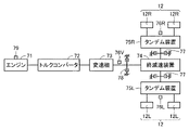
図4は、実施形態に基づくモータグレーダ1における走行輪の駆動制御に関する構成を概略的に示す図である。実施形態のモータグレーダ1は、エンジン71の駆動力が後輪12に伝達され後輪12を駆動輪とする、後輪駆動車である。エンジン71は、リアフレーム21に支持されている。オペレータによるアクセルペダル36の操作に従ってエンジン71への燃料の供給量が制御されることにより、エンジン71の回転数が制御される。エンジン71の回転数は、エンジン回転数センサ79によって検出される。
図4に示されるように、エンジン71からの駆動力を後輪12に伝達するための動力伝達装置は、トルクコンバータ72と、変速機73と、終減速装置74と、タンデム装置75L,75Rとを有している。
トルクコンバータ72は、エンジン71の出力側に接続されている。トルクコンバータ72は、オイルを媒体としてエンジン71からの駆動力を伝達する流体クラッチである。トルクコンバータ72には、トルクコンバータ72の入力側と出力側とを直結するロックアップクラッチが設けられていてもよい。オペレータの選択によって、流体クラッチとロックアップクラッチとのいずれを介して動力を伝達するかが切り替えられてもよい。
変速機73は、複数の速度段に対応した複数のクラッチを有している。各クラッチの連結状態および非連結状態が切り替えられることにより、変速機73は減速比を複数段階に切り替えることができる。変速機73の出力軸には速度センサ76Vが設けられている。速度センサ76Vは、変速機73の出力軸の回転数を検出する。
変速機73の出力軸に、終減速装置74が接続されている。変速機73から出力された駆動力は、終減速装置74を介して、左右のタンデム装置75L,75Rに伝達される。左のタンデム装置75Lには、一対の左後輪12Lが接続されている。右のタンデム装置75Rには、一対の右後輪12Rが接続されている。エンジン71は、トルクコンバータ72、変速機73、終減速装置74およびタンデム装置75L,75Rを介して、左後輪12Lと右後輪12Rとを回転駆動する。
回転速度センサ76Lは、左後輪12Lの回転速度を検出する。回転速度センサ76Lは、たとえばタンデム装置75Lにおける回転軸の回転速度を測定することにより、左後輪12Lの回転速度を測定する。回転速度センサ76Rは、右後輪12Rの回転速度を検出する。回転速度センサ76Rは、たとえばタンデム装置75Rにおける回転軸の回転速度を測定することにより、右後輪12Rの回転速度を測定する。
変速機73の出力軸に、パーキングブレーキ78が設けられている。パーキングブレーキは、モータグレーダ1の走行停止状態を維持するために用いられるブレーキである。パーキングブレーキ78は、たとえばネガティブ式のブレーキである。キャブ3内に配置されたパーキングブレーキスイッチをオペレータが操作することにより、パーキングブレーキ78の制動状態と非制動状態とが切り替えられる。パーキングブレーキスイッチは、右側コンソール32Rに設けられていてもよい。パーキングブレーキスイッチは、作業機レバー35Rの後方に配置されていてもよい。
終減速装置74とタンデム装置75L,75Rとの間に、オペレータによるブレーキペダル37の操作により駆動するサービスブレーキ77が設けられている。サービスブレーキ77は、モータグレーダ1の走行中に走行速度を減少させるために用いられるブレーキである。サービスブレーキ77の制動力は、ブレーキペダル37の操作量に応じて調整可能である。サービスブレーキ77は、たとえばポジティブ式のブレーキである。
図5は、モータグレーダ1のシステム構成を示すブロック図である。実施形態のモータグレーダ1は、コントローラ80を備えている。コントローラ80は、モータグレーダ1全体の動作を制御するコントローラであり、CPU(Central Processing Unit)、不揮発性メモリ、タイマなどにより構成されている。
ステアリング操作部を構成するステアリング操作レバー5およびステアリングホイール34と、作業機操作部に相当する作業機レバー35L,35Rと、アクセルペダル36と、ブレーキペダル37とは、キャブ3内に配置されており、キャブ3に搭乗したオペレータによって操作される。ステアリング操作レバー5、ステアリングホイール34、作業機レバー35L,35R、アクセルペダル36およびブレーキペダル37の各々の操作方向および操作量を検出するセンサが設けられている。センサにより検出された検出信号が、コントローラ80に入力される。
作業機ロックスイッチ61、ブレーキ保持スイッチ62およびパーキングブレーキスイッチ63は、キャブ3内に配置されており、キャブ3に搭乗したオペレータによって操作される。作業機ロックスイッチ61、ブレーキ保持スイッチ62およびパーキングブレーキスイッチ63の各々の操作状態を検出するセンサが設けられている。センサにより検出された検出信号が、コントローラ80に入力される。
速度センサ76Vは、変速機73の出力軸の回転数を検出することにより、モータグレーダ1の移動時(走行時)の移動速度(モータグレーダ1の走行速度)を検出する。速度センサ76Vは、たとえばGNSS(Global Navigation Satellite System)を利用して、モータグレーダ1の移動速度を検出してもよい。回転速度センサ76L,76Rは、左後輪12Lおよび右後輪12Rの回転速度をそれぞれ検出する。エンジン回転数センサ79は、エンジン71の回転数を検出する。速度センサ76V、回転速度センサ76L,76Rおよびエンジン回転数センサ79により検出された検出信号が、コントローラ80に入力される。
コントローラ80は、ブレーキ制御部82を有している。ブレーキ制御部82は、自動ブレーキ保持制御を実行する。メモリには、モータグレーダ1の走行速度に係る閾値が記憶されている。ブレーキ制御部82は、ブレーキ保持スイッチ62が操作されて自動ブレーキ保持機能を有効にする設定がされている状態で、オペレータによるブレーキペダル37の操作によりモータグレーダ1の走行速度が閾値以下となったときに、制動力を保持してモータグレーダ1の走行停止状態を維持する。ブレーキ制御部82は、モータグレーダ1の走行停止状態を維持しているときにオペレータによりアクセルペダル36が操作されると、制動力の保持を解除する。
コントローラ80は、無効化部84を有している。無効化部84は、モータグレーダ1が作業機4による作業中であるか否かを判別する。無効化部84は、モータグレーダ1が作業機4による作業中の場合には、自動ブレーキ保持制御を無効とする。
コントローラ80は、オペレータによる作業機操作部(作業機レバー35L,35R)の操作に従って、各種の油圧アクチュエータ、具体的にはリフトシリンダ44,45、ドローバシフトシリンダ46、チルトシリンダ48および旋回モータ49を動作させる制御信号を出力する。油圧アクチュエータが制御されることにより、作業機4の動作が制御される。
より詳細には、モータグレーダ1は、エンジン71の駆動力を受けて駆動される図示しない油圧ポンプと、図示しないメインバルブとを備え、油圧ポンプから吐出された作動油がメインバルブを介して各種の油圧アクチュエータに供給されるように構成されている。メインバルブは、ロッド状のスプールを軸方向に動かして油圧アクチュエータへの作動油の供給量を調整するスプール方式の弁である。コントローラ80は、メインバルブのスプールを移動させる制御信号を、メインバルブに送信する。これにより、各種の油圧アクチュエータの動作が制御される。
コントローラ80はまた、オペレータによる作業機ロックスイッチ61の操作に従って、作業機4をロック状態とする制御信号を出力する。コントローラ80は、メインバルブのスプールを停止させて油圧アクチュエータへの作動油の供給量が変動しないように制御することで、オペレータが作業機レバー35L,35Rを操作しても作業機4が動作しないロック状態とする。
コントローラ80は、オペレータによるステアリング操作部およびアクセルペダル36の操作に従った制御信号を、エンジン71および変速機73に送信する。エンジン71および変速機73が制御されることにより、モータグレーダ1の走行動作が制御される。
コントローラ80は、オペレータによるパーキングブレーキスイッチ63の操作に従った制御信号を、パーキングブレーキ78に送信する。パーキングブレーキ78が制御されることにより、モータグレーダ1が走行停止状態に維持され、またはモータグレーダ1が走行可能な状態となる。
コントローラ80は、オペレータによるブレーキペダル37の操作に従った制御信号を、サービスブレーキ77に送信する。サービスブレーキ77が作動することにより、モータグレーダ1の走行速度が減少することになる。
コントローラ80は、通知部90に制御信号を送信する。通知部90は、モータグレーダ1の運転状態に関する情報を、オペレータに通知する。通知部90はたとえば、作業機ロックスイッチ61の操作により作業機4がロックされているときに点灯し作業機4のロックが解除されると消灯する、作業機ロック表示灯を含んでもよい。通知部90はたとえば、ブレーキ保持スイッチ62の操作により自動ブレーキ保持機能が有効であるときに点灯し自動ブレーキ保持機能が無効であるときに消灯する、自動ブレーキ保持表示灯を含んでもよい。
作業機ロック表示灯および自動ブレーキ保持表示灯は、各々、作業機ロックスイッチ61およびブレーキ保持スイッチ62に設けられてもよい。または、通知部90は、モニタを含んでもよく、作業機ロック表示灯および自動ブレーキ保持表示灯はモニタに表示されてもよい。作業機ロック表示灯および自動ブレーキ保持表示灯が点灯するときに、モニタにポップアップ表示されてもよい。
モニタには、モータグレーダ1の走行速度、燃料残量、作動油温度などの車体情報が表示されてもよい。車体後方の視認用のリアビューカメラなどの撮像装置をモータグレーダ1が備えている場合に、撮像装置による撮像画像がモニタに表示されてもよい。
図6は、自動ブレーキ保持機能のONおよびOFFを切り替える制御ロジックの一例を示す模式図である。図7は、自動ブレーキ保持制御OFFの状態における処理の流れを示すフロー図である。
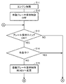
エンジン71が始動されると(ステップS11)、自動ブレーキ保持制御OFFの状態とされる(ステップS12)。自動ブレーキ保持制御OFFの状態において、コントローラ80は、第1条件が成立したか否かを判定する。
第1条件は、ブレーキ保持スイッチ62がONとされていることと、作業機4による作業中でないことと、の全てが成立することである。第1条件が成立することは、自動ブレーキ保持機能を有効にしたい、かつ、作業機4による作業はしない、というオペレータの意図が示されることであると言える。ブレーキ保持スイッチ62がONであり(ステップS13においてYES)、かつ、作業機4による作業中でなければ(ステップS14においてNO)、第1条件が成立し、自動ブレーキ保持制御OFFの状態から、自動ブレーキ保持制御READYの状態へと変更される(ステップS15)。
ステップS14の判断において、コントローラ80は、たとえば、作業機ロックスイッチ61の操作状態に基づいて、作業機4による作業中であるか否かを判別してもよい。具体的には、モータグレーダ1の回送走行中には作業機4がロックされるので、作業機ロックスイッチ61がONとされ作業機4がロック状態であるならば、作業中ではなく走行中であると判別され、作業機ロックスイッチ61がOFFとされ作業機4のロックが解除されているならば、作業中であると判別されてもよい。
ステップS14の判断において、コントローラ80は、たとえば、作業機操作部(作業機レバー35L,35R)の操作状態に基づいて、作業機4による作業中であるか否かを判別してもよい。作業中にはオペレータが作業機レバー35L,35Rを操作するので、いずれか1つまたは複数の作業機レバー35L,35Rを操作していることを示す電気信号がコントローラ80に入力されていれば、作業中であると判別されてもよい。作業機レバー35L,35Rにオペレータが触れていることを検出するタッチセンサを設け、タッチセンサによりオペレータが作業機レバー35L,35Rに触れていることが検出されれば、作業中であると判別されてもよい。
ステップS14の判断において、コントローラ80は、作業機レバー35L,35Rの操作状態に加えて、ステアリング操作部の操作状態に基づいて作業機4による作業中であるか否かを判別してもよい。たとえば、一定時間(一例として60秒間)オペレータによる作業機レバー35L,35Rの操作がなく、かつ、その一定時間が経過した時点でステアリング操作部が操作されていることを示す電気信号がコントローラ80に入力されていれば、作業中でないと判別されてもよい。
ブレーキ保持スイッチ62がOFFであるか(ステップS13においてNO)、または、作業機4による作業中であれば(ステップS14においてYES)、第1条件は不成立であり、ステップS13の判断に戻り、自動ブレーキ保持制御OFFの状態のままとされる。
図8は、自動ブレーキ保持制御READYの状態における処理の流れを示すフロー図である。自動ブレーキ保持制御READYの状態とは、作業に関する条件と、ブレーキ保持スイッチ62に関する条件は成立したが、モータグレーダ1が走行を停止していないので、モータグレーダ1の走行停止状態を維持する制御を実行できていないものの、モータグレーダ1が走行を停止したならば直ちにモータグレーダ1の走行停止状態を維持する制御を実行できる状態、であると言える。自動ブレーキ保持制御READYの状態において、コントローラ80はまず、第2条件が成立したか否かを判定する。
第2条件は、ブレーキ保持スイッチ62がOFFとされていることと、作業機4による作業中であることと、のいずれかが成立することである。第2条件が成立することは、オペレータのいずれかの操作によって、ブレーキ保持機能を解除したいというオペレータの意図が示されることであると言える。ブレーキ保持スイッチ62がOFFであるか(ステップS21においてYES)、または、作業機4による作業中であれば(ステップS22においてYES)、第2条件が成立し、自動ブレーキ保持制御READYの状態から、自動ブレーキ保持制御OFFの状態に移り(ステップS23)、自動ブレーキ保持制御は解除される。作業機4による作業中であると判別された場合には、自動ブレーキ保持制御が無効化される。
ブレーキ保持スイッチ62がONであり(ステップS21においてNO)、かつ、作業機4による作業中でなければ(ステップS22においてNO)、第2条件は不成立であり、コントローラ80は続いて、第3条件が成立したか否かを判定する。
第3条件は、モータグレーダ1の走行速度が所定の閾値(一例として1.0km/h)以下となり停車したと判断されることと、ブレーキペダル37の操作が所定時間(一例として3秒間)以上継続していることと、アクセルペダル36の操作量が所定の閾値(一例として0%)以下であることと、の全てが成立することである。第3条件が成立することは、モータグレーダ1の走行を停止させようとするオペレータの意図が示されることであると言える。走行速度の閾値は0km/hであってもよく、モータグレーダ1が完全停止したときにのみ自動ブレーキ保持制御ONとなってもよい。
オペレータがブレーキペダル37を操作することで、走行速度が閾値以下になり(ステップS24においてYES)、ブレーキペダル37の操作時間が所定時間継続され(ステップS25においてYES)、かつ、アクセルペダル36の操作量が閾値以下であれば(ステップS26においてYES)、第3条件が成立し、自動ブレーキ保持制御READYの状態から、自動ブレーキ保持制御ONの状態へと変更される(ステップS27)。
走行速度が閾値より大きいか(ステップS24においてNO)、ブレーキペダル37の操作時間が所定時間継続しないか(ステップS25においてNO)、または、アクセルペダル36の操作量が閾値より大きければ(ステップS26においてNO)、第3条件は不成立であり、ステップS21の判断に戻り、自動ブレーキ保持制御READYの状態のままとされる。
自動ブレーキ保持制御ONの状態で、コントローラ80は、パーキングブレーキ78を制動状態にする、またはサービスブレーキ77を制動状態にすることで、制動力を保持してモータグレーダ1の走行停止状態を維持する。この際、コントローラ80は、燃費向上およびブレーキ保護のため、変速機73をニュートラルに変速してもよい。モニタに速度段設定が表示される場合には、自動ブレーキ保持制御に伴って変速機73の設定がニュートラルに変更されても、モニタの表示は変更せずに元の速度段設定の表示のままにしてもよい。オペレータがブレーキペダル37を操作することで点灯する制動灯を、ブレーキペダル37から足を離しても点灯したままとしてもよい。自動ブレーキ保持機能が有効であることを、モニタに表示するなどして、オペレータに通知してもよい。
図9は、自動ブレーキ保持制御ONの状態における処理の流れを示すフロー図である。自動ブレーキ保持制御ONの状態において、コントローラ80はまず、第2条件が成立したか否かを判定する。
ブレーキ保持スイッチ62がOFFであるか(ステップS31においてYES)、または、作業機4による作業中であれば(ステップS32においてYES)、第2条件が成立し、自動ブレーキ保持制御ONの状態から自動ブレーキ保持制御OFFの状態に移り、自動ブレーキ保持制御は解除されることになる。ブレーキ保持スイッチ62がONであり(ステップS31においてNO)、かつ、作業機4による作業中でなければ(ステップS32においてNO)、第2条件は不成立であり、コントローラ80は続いて、第4条件が成立したか否かを判定する。
第4条件は、ブレーキ保持スイッチ62がONとされていることと、作業機4による作業中でないことと、アクセルペダル36の操作量が所定の閾値以上であることと、の全てが成立することである。第4条件が成立することは、自動ブレーキ保持機能は有効としたままでモータグレーダ1を走行させようとするオペレータの意図が示されることであると言える。なお、第4条件に含まれる3つの条件のうち、作業機4による作業中でないことと、ブレーキ保持スイッチ62がONとされていることとは、第1条件にも含まれる条件である。
ブレーキ保持スイッチ62がONであり、かつ、作業機4による作業中でないことは、第2条件が不成立であることの判定において判断済みである。さらに、アクセルペダル36の操作量が閾値以上であれば(ステップS34においてYES)、第4条件が成立し、自動ブレーキ保持制御ONの状態から、自動ブレーキ保持制御READYの状態へと変更される(ステップS35)。つまり、オペレータがアクセルペダル36を操作することで、制動力の保持が解除され、モータグレーダ1は走行可能な状態となる。
なお、ステップS27でコントローラ80が変速機73をニュートラルに変速していた場合には、第4条件が成立して自動ブレーキ保持制御READYの状態に移ったときに、コントローラ80は変速機73を元の速度段設定に復帰させる。
アクセルペダル36の操作量が閾値より小さければ(ステップS34においてNO)、第4条件は不成立であり、ステップS31の判断に戻り、自動ブレーキ保持制御ONの状態のままとされる。
上述した説明と一部重複する記載もあるが、本実施形態の特徴的な構成および作用効果についてまとめて記載すると、以下の通りである。
図5に示されるように、コントローラ80は、ブレーキ制御部82と、無効化部84とを有している。ブレーキ制御部82は、ブレーキペダル37の操作によりモータグレーダ1の走行速度が閾値以下となったときに制動力を保持してモータグレーダ1の走行停止状態を維持し、アクセルペダル36の操作により制動力の保持を解除する、自動ブレーキ保持制御を実行する。図6~9に示されるように、無効化部84は、モータグレーダ1が作業機4による作業中であるか否かを判別し、作業中の場合には自動ブレーキ保持制御を無効とする。
モータグレーダ1に自動ブレーキ保持制御を適用することにより、モータグレーダ1を操作するオペレータの疲労を軽減することができる。モータグレーダ1が作業中の場合には自動ブレーキ保持制御が無効にされるので、モータグレーダ1が微速で走行しながらの作業に支障をきたすことがない。したがって、モータグレーダ1の操作性を向上することができる。
図3,5に示されるように、モータグレーダ1は、作業機4の動作を制限する作業機ロックスイッチ61をさらに備えている。コントローラ80は、作業機ロックスイッチ61の操作状態に基づいて、モータグレーダ1が作業機4による作業中であるか否かを判別してもよい。モータグレーダ1の回送走行中には作業機4がロックされるので、作業機ロックスイッチ61がONとされ作業機4がロック状態であるならば、作業中ではなく走行中であると判別され、作業機ロックスイッチ61がOFFとされ作業機4のロックが解除されているならば、作業中であると判別されてもよい。これにより、モータグレーダ1が作業機4による作業中であるか否かを精度よく判別することができる。
図3,5に示されるように、モータグレーダ1は、オペレータが作業機4を操作するための作業機レバー35L,35Rをさらに備えている。コントローラ80は、作業機レバー35L,35Rの操作状態に基づいて、モータグレーダ1が作業機4による作業中であるか否かを判別してもよい。作業中にはオペレータが作業機レバー35L,35Rを操作するので、オペレータが作業機レバー35L,35Rを操作している、またはオペレータが作業機レバー35L,35Rに触れていることが検出されれば、作業中であると判別されてもよい。これにより、モータグレーダ1が作業機4による作業中であるか否かを精度よく判別することができる。
図3,5に示されるように、モータグレーダ1は、オペレータがモータグレーダ1の走行方向を操作するためのステアリング操作部をさらに備えている。コントローラ80は、ステアリング操作部の操作状態に基づいて、モータグレーダ1が作業機4による作業中であるか否かを判別してもよい。たとえば、所定の期間内におけるステアリングホイール34の操作の頻度が、ステアリング操作レバー5の操作の頻度を大幅に下回ったときに作業中であると判別されてもよい。または、オペレータによる作業機レバー35L,35Rの操作がなく、かつ、ステアリングホイール34が操作されていることが検出されれば、作業中ではなく回送走行中であると判別されてもよい。これにより、モータグレーダ1が作業機4による作業中であるか否かを精度よく判別することができる。
図3,5に示されるように、モータグレーダ1は、自動ブレーキ保持制御を有効にする設定を選択するために操作されるブレーキ保持スイッチ62をさらに備えている。図9に示されるように、コントローラ80は、ブレーキ保持スイッチ62の操作により自動ブレーキ保持制御を有効にする設定がされている状態で、モータグレーダ1が作業機4による作業中であるか否かを判別し、作業中でないと判別した場合に、自動ブレーキ保持制御を実行する。これにより、モータグレーダ1の作業に影響を及ぼすことなく自動ブレーキ保持機能を用いることができる。
上記の実施形態では、自動ブレーキ保持機能を有効にするか無効にするかを選択するためにオペレータによって操作されるブレーキ保持スイッチ62を備える例について説明した。ブレーキ保持スイッチ62に替えて、自動ブレーキ保持機能の有効と無効とを、タッチパネルであるモニタを操作して選択可能とするなど、他の任意の手段を適用してもよい。
実施形態では、作業機レバー35L,35Rが電気式のレバーである例について説明した。オペレータが作業機4を操作するための操作レバーは、油圧式のレバーであってもよい。この場合、レバーの操作によって油圧が変動することを圧力センサで検出することで、レバーの操作状態を判断することができる。その判断の結果に基づいて、作業機4による作業中であるか否かを判別してもよい。
実施形態では、エンジン71からの駆動力を後輪12に伝達するための動力伝達装置が機械式の変速機73を有する例について説明した。動力伝達装置は、エンジン71で油圧ポンプを駆動することにより圧油を発生させ、油圧ポンプから吐出した圧油によって油圧モータが駆動されることで回転力が再び発生する、HST(Hydraulic Static Transmission)を有してもよい。
モータグレーダ1は、後輪駆動車に限られず、全輪駆動車であってもよい。この場合、エンジン71から後輪12への動力伝達装置は、機械式の変速機73を有してもよく、HSTを有してもよい。エンジン71から前輪11への動力伝達装置は、HSTを有してもよい。
実施形態では、作業機械の一例としてモータグレーダ1を挙げているが、モータグレーダ1に限らず、ホイールローダなどの他の種類の走行しながら作業を行う作業機械にも適用可能である。さらに、エンジンで発電機を駆動するディーゼルエレクトリック車、二次電池式電気駆動車(BEV)、燃料電池駆動車(FCV)など他の駆動システムに、実施形態の思想を適用してもよい。
今回開示された実施形態はすべての点で例示であって、制限的なものではないと考えられるべきである。本発明の範囲は上記した説明ではなくて請求の範囲によって示され、請求の範囲と均等の意味および範囲内でのすべての変更が含まれることが意図される。
1 モータグレーダ、3 キャブ、4 作業機、5 ステアリング操作レバー、11 前輪、12 後輪、12L 左後輪、12R 右後輪、30 床面、31 運転席、32F,32L,32R コンソール、34 ステアリングホイール、35L,35R 作業機レバー、36 アクセルペダル、37 ブレーキペダル、40 ドローバ、41 旋回サークル、42 ブレード、44,45 リフトシリンダ、46 ドローバシフトシリンダ、48 チルトシリンダ、49 旋回モータ、54 アーティキュレートシリンダ、61 作業機ロックスイッチ、62 ブレーキ保持スイッチ、63 パーキングブレーキスイッチ、71 エンジン、72 トルクコンバータ、73 変速機、74 終減速装置、75L,75R タンデム装置、76L,76R 回転速度センサ、76V 速度センサ、77 サービスブレーキ、78 パーキングブレーキ、79 エンジン回転数センサ、80 コントローラ、82 ブレーキ制御部、84 無効化部、90 通知部。
Claims (7)
- 走行する車体と、
前記車体に支持された作業機と、
前記車体の走行速度を増加するために操作されるアクセル操作装置と、
前記車体の走行速度を減少するために操作されるブレーキ操作装置と、
コントローラとを備え、
前記コントローラは、
前記ブレーキ操作装置の操作により前記車体の走行速度が閾値以下となったときに制動力を保持して前記車体の走行停止状態を維持し、前記アクセル操作装置の操作により制動力の保持を解除する、自動ブレーキ保持制御を実行し、
前記作業機による作業中であるか否かを判別し、作業中の場合には前記自動ブレーキ保持制御を無効とする、
作業機械。 - 前記作業機の動作を制限する作業機ロック装置をさらに備え、
前記コントローラは、前記作業機ロック装置の操作状態に基づいて作業中であるか否かを判別する、請求項1に記載の作業機械。 - オペレータが前記作業機を操作するための作業機操作部をさらに備え、
前記コントローラは、前記作業機操作部の操作状態に基づいて作業中であるか否かを判別する、請求項1に記載の作業機械。 - オペレータが前記車体の走行方向を操作するためのステアリング操作部をさらに備え、
前記コントローラは、前記ステアリング操作部の操作状態に基づいて作業中であるか否かを判別する、請求項3に記載の作業機械。 - 前記自動ブレーキ保持制御を有効にする設定を選択するために操作されるスイッチをさらに備え、
前記コントローラは、前記スイッチの操作により前記自動ブレーキ保持制御を有効にする設定がされている状態で、前記作業機による作業中でないと判別した場合に、前記自動ブレーキ保持制御を実行する、請求項1から請求項4のいずれか1項に記載の作業機械。 - 走行する車体と、
前記車体に支持された作業機と、
前記車体の走行速度を増加するために操作されるアクセル操作装置と、
前記車体の走行速度を減少するために操作されるブレーキ操作装置と、
を備える作業機械の制御装置であって、
前記ブレーキ操作装置の操作により前記車体の走行速度が閾値以下となったときに制動力を保持して前記車体の走行停止状態を維持し、前記アクセル操作装置の操作により制動力の保持を解除する、自動ブレーキ保持制御を実行し、
前記作業機による作業中であるか否かを判別し、作業中の場合には前記自動ブレーキ保持制御を無効とする、作業機械の制御装置。 - 走行する車体と、
前記車体に支持された作業機と、
前記車体の走行速度を増加するために操作されるアクセル操作装置と、
前記車体の走行速度を減少するために操作されるブレーキ操作装置と、
を備える作業機械の制御方法であって、
前記ブレーキ操作装置の操作により前記車体の走行速度が閾値以下となったときに制動力を保持して前記車体の走行停止状態を維持し、前記アクセル操作装置の操作により制動力の保持を解除する、自動ブレーキ保持制御を実行することと、
前記作業機による作業中であるか否かを判別し、作業中の場合には前記自動ブレーキ保持制御を無効とすることと、を備える、作業機械の制御方法。
Priority Applications (3)
| Application Number | Priority Date | Filing Date | Title |
|---|---|---|---|
| CN202180071584.XA CN116368277A (zh) | 2020-12-10 | 2021-11-05 | 作业机械、作业机械的控制装置以及作业机械的控制方法 |
| US18/036,448 US20230417021A1 (en) | 2020-12-10 | 2021-11-05 | Work machine, controller for work machine, and method of controlling work machine |
| EP21903076.4A EP4206406A1 (en) | 2020-12-10 | 2021-11-05 | Work machine, device for controlling work machine, and method for controlling work machine |
Applications Claiming Priority (2)
| Application Number | Priority Date | Filing Date | Title |
|---|---|---|---|
| JP2020-204927 | 2020-12-10 | ||
| JP2020204927A JP2022092241A (ja) | 2020-12-10 | 2020-12-10 | 作業機械、作業機械の制御装置、および作業機械の制御方法 |
Publications (1)
| Publication Number | Publication Date |
|---|---|
| WO2022123972A1 true WO2022123972A1 (ja) | 2022-06-16 |
Family
ID=81973662
Family Applications (1)
| Application Number | Title | Priority Date | Filing Date |
|---|---|---|---|
| PCT/JP2021/040694 WO2022123972A1 (ja) | 2020-12-10 | 2021-11-05 | 作業機械、作業機械の制御装置、および作業機械の制御方法 |
Country Status (5)
| Country | Link |
|---|---|
| US (1) | US20230417021A1 (ja) |
| EP (1) | EP4206406A1 (ja) |
| JP (1) | JP2022092241A (ja) |
| CN (1) | CN116368277A (ja) |
| WO (1) | WO2022123972A1 (ja) |
Citations (5)
| Publication number | Priority date | Publication date | Assignee | Title |
|---|---|---|---|---|
| JPH08142819A (ja) * | 1994-11-22 | 1996-06-04 | Fujitsu Ten Ltd | ブレーキホールド制御装置 |
| JPH09142270A (ja) * | 1995-11-22 | 1997-06-03 | Honda Motor Co Ltd | 車両の制動力保持装置 |
| JP2000033859A (ja) | 1998-07-17 | 2000-02-02 | Mitsubishi Electric Corp | 停車ブレーキ装置 |
| JP2001341624A (ja) * | 2000-06-05 | 2001-12-11 | Mitsubishi Electric Corp | 停車ブレーキ装置 |
| JP2005299102A (ja) * | 2004-04-07 | 2005-10-27 | Kobelco Contstruction Machinery Ltd | 旋回式作業機械 |
-
2020
- 2020-12-10 JP JP2020204927A patent/JP2022092241A/ja active Pending
-
2021
- 2021-11-05 US US18/036,448 patent/US20230417021A1/en active Pending
- 2021-11-05 WO PCT/JP2021/040694 patent/WO2022123972A1/ja active Application Filing
- 2021-11-05 CN CN202180071584.XA patent/CN116368277A/zh active Pending
- 2021-11-05 EP EP21903076.4A patent/EP4206406A1/en active Pending
Patent Citations (5)
| Publication number | Priority date | Publication date | Assignee | Title |
|---|---|---|---|---|
| JPH08142819A (ja) * | 1994-11-22 | 1996-06-04 | Fujitsu Ten Ltd | ブレーキホールド制御装置 |
| JPH09142270A (ja) * | 1995-11-22 | 1997-06-03 | Honda Motor Co Ltd | 車両の制動力保持装置 |
| JP2000033859A (ja) | 1998-07-17 | 2000-02-02 | Mitsubishi Electric Corp | 停車ブレーキ装置 |
| JP2001341624A (ja) * | 2000-06-05 | 2001-12-11 | Mitsubishi Electric Corp | 停車ブレーキ装置 |
| JP2005299102A (ja) * | 2004-04-07 | 2005-10-27 | Kobelco Contstruction Machinery Ltd | 旋回式作業機械 |
Also Published As
| Publication number | Publication date |
|---|---|
| US20230417021A1 (en) | 2023-12-28 |
| JP2022092241A (ja) | 2022-06-22 |
| CN116368277A (zh) | 2023-06-30 |
| EP4206406A1 (en) | 2023-07-05 |
Similar Documents
| Publication | Publication Date | Title |
|---|---|---|
| US9133604B2 (en) | Hydraulic control device for work machine | |
| JP6577433B2 (ja) | ホイール式油圧ショベル | |
| JP3907464B2 (ja) | トラクタ | |
| WO2021181823A1 (ja) | モータグレーダおよび表示制御方法 | |
| WO2022123972A1 (ja) | 作業機械、作業機械の制御装置、および作業機械の制御方法 | |
| WO2022176991A1 (ja) | 作業機械の制御システム、作業機械の制御方法、および作業機械 | |
| US11794577B2 (en) | Work machine and control method thereof | |
| WO2016085369A1 (en) | A method and control unit for preventing rollover of a tractor unit of a working machine | |
| JPH023505A (ja) | 作業車両のラムロック制御装置 | |
| JP5070788B2 (ja) | 作業車 | |
| JP2019206873A (ja) | ホイール式作業機械 | |
| JP4361422B2 (ja) | 作業車両 | |
| JP2008082124A (ja) | トラクタ | |
| JP6670268B2 (ja) | トラクタ | |
| JP4730551B2 (ja) | 作業車両 | |
| JP4996429B2 (ja) | 作業車両の独立型サスペンション | |
| JP6852257B2 (ja) | 作業車両 | |
| JP2021024330A (ja) | 作業車両 | |
| JP4796432B2 (ja) | 作業車両の走行停止制御装置 | |
| JP7490127B2 (ja) | モータグレーダおよび表示制御方法 | |
| JP2022095411A (ja) | 作業車の走行制御装置 | |
| JP2022047169A (ja) | 乗用型農作業車 | |
| JP2021116905A (ja) | 作業車両 | |
| JP4354890B2 (ja) | 作業車両の操向装置 | |
| JP2003095599A (ja) | 作業用車両の安全装置 |
Legal Events
| Date | Code | Title | Description |
|---|---|---|---|
| 121 | Ep: the epo has been informed by wipo that ep was designated in this application |
Ref document number: 21903076 Country of ref document: EP Kind code of ref document: A1 |
|
| ENP | Entry into the national phase |
Ref document number: 2021903076 Country of ref document: EP Effective date: 20230328 |
|
| WWE | Wipo information: entry into national phase |
Ref document number: 18036448 Country of ref document: US |
|
| NENP | Non-entry into the national phase |
Ref country code: DE |