WO2022113231A1 - モータの制御方法、流体供給装置、車高調整装置、鞍乗型車両 - Google Patents
モータの制御方法、流体供給装置、車高調整装置、鞍乗型車両 Download PDFInfo
- Publication number
- WO2022113231A1 WO2022113231A1 PCT/JP2020/044005 JP2020044005W WO2022113231A1 WO 2022113231 A1 WO2022113231 A1 WO 2022113231A1 JP 2020044005 W JP2020044005 W JP 2020044005W WO 2022113231 A1 WO2022113231 A1 WO 2022113231A1
- Authority
- WO
- WIPO (PCT)
- Prior art keywords
- motor
- screw
- nut
- nut member
- supply device
- Prior art date
- Legal status (The legal status is an assumption and is not a legal conclusion. Google has not performed a legal analysis and makes no representation as to the accuracy of the status listed.)
- Ceased
Links
Images

Classifications
-
- B—PERFORMING OPERATIONS; TRANSPORTING
- B62—LAND VEHICLES FOR TRAVELLING OTHERWISE THAN ON RAILS
- B62K—CYCLES; CYCLE FRAMES; CYCLE STEERING DEVICES; RIDER-OPERATED TERMINAL CONTROLS SPECIALLY ADAPTED FOR CYCLES; CYCLE AXLE SUSPENSIONS; CYCLE SIDECARS, FORECARS, OR THE LIKE
- B62K25/00—Axle suspensions
- B62K25/04—Axle suspensions for mounting axles resiliently on cycle frame or fork
- B62K25/12—Axle suspensions for mounting axles resiliently on cycle frame or fork with rocking arm pivoted on each fork leg
- B62K25/14—Axle suspensions for mounting axles resiliently on cycle frame or fork with rocking arm pivoted on each fork leg with single arm on each fork leg
- B62K25/16—Axle suspensions for mounting axles resiliently on cycle frame or fork with rocking arm pivoted on each fork leg with single arm on each fork leg for front wheel
-
- B—PERFORMING OPERATIONS; TRANSPORTING
- B60—VEHICLES IN GENERAL
- B60G—VEHICLE SUSPENSION ARRANGEMENTS
- B60G17/00—Resilient suspensions having means for adjusting the spring or vibration-damper characteristics, for regulating the distance between a supporting surface and a sprung part of vehicle or for locking suspension during use to meet varying vehicular or surface conditions, e.g. due to speed or load
- B60G17/02—Spring characteristics, e.g. mechanical springs and mechanical adjusting means
- B60G17/027—Mechanical springs regulated by fluid means
- B60G17/0272—Mechanical springs regulated by fluid means the mechanical spring being a coil spring
-
- B—PERFORMING OPERATIONS; TRANSPORTING
- B62—LAND VEHICLES FOR TRAVELLING OTHERWISE THAN ON RAILS
- B62K—CYCLES; CYCLE FRAMES; CYCLE STEERING DEVICES; RIDER-OPERATED TERMINAL CONTROLS SPECIALLY ADAPTED FOR CYCLES; CYCLE AXLE SUSPENSIONS; CYCLE SIDECARS, FORECARS, OR THE LIKE
- B62K25/00—Axle suspensions
- B62K25/04—Axle suspensions for mounting axles resiliently on cycle frame or fork
- B62K25/06—Axle suspensions for mounting axles resiliently on cycle frame or fork with telescopic fork, e.g. including auxiliary rocking arms
- B62K25/08—Axle suspensions for mounting axles resiliently on cycle frame or fork with telescopic fork, e.g. including auxiliary rocking arms for front wheel
-
- B—PERFORMING OPERATIONS; TRANSPORTING
- B62—LAND VEHICLES FOR TRAVELLING OTHERWISE THAN ON RAILS
- B62K—CYCLES; CYCLE FRAMES; CYCLE STEERING DEVICES; RIDER-OPERATED TERMINAL CONTROLS SPECIALLY ADAPTED FOR CYCLES; CYCLE AXLE SUSPENSIONS; CYCLE SIDECARS, FORECARS, OR THE LIKE
- B62K25/00—Axle suspensions
- B62K25/04—Axle suspensions for mounting axles resiliently on cycle frame or fork
- B62K25/12—Axle suspensions for mounting axles resiliently on cycle frame or fork with rocking arm pivoted on each fork leg
- B62K25/14—Axle suspensions for mounting axles resiliently on cycle frame or fork with rocking arm pivoted on each fork leg with single arm on each fork leg
- B62K25/20—Axle suspensions for mounting axles resiliently on cycle frame or fork with rocking arm pivoted on each fork leg with single arm on each fork leg for rear wheel
-
- B—PERFORMING OPERATIONS; TRANSPORTING
- B62—LAND VEHICLES FOR TRAVELLING OTHERWISE THAN ON RAILS
- B62K—CYCLES; CYCLE FRAMES; CYCLE STEERING DEVICES; RIDER-OPERATED TERMINAL CONTROLS SPECIALLY ADAPTED FOR CYCLES; CYCLE AXLE SUSPENSIONS; CYCLE SIDECARS, FORECARS, OR THE LIKE
- B62K25/00—Axle suspensions
- B62K25/04—Axle suspensions for mounting axles resiliently on cycle frame or fork
- B62K25/28—Axle suspensions for mounting axles resiliently on cycle frame or fork with pivoted chain-stay
- B62K25/283—Axle suspensions for mounting axles resiliently on cycle frame or fork with pivoted chain-stay for cycles without a pedal crank, e.g. motorcycles
-
- F—MECHANICAL ENGINEERING; LIGHTING; HEATING; WEAPONS; BLASTING
- F04—POSITIVE - DISPLACEMENT MACHINES FOR LIQUIDS; PUMPS FOR LIQUIDS OR ELASTIC FLUIDS
- F04B—POSITIVE-DISPLACEMENT MACHINES FOR LIQUIDS; PUMPS
- F04B49/00—Control, e.g. of pump delivery, or pump pressure of, or safety measures for, machines, pumps, or pumping installations, not otherwise provided for, or of interest apart from, groups F04B1/00 - F04B47/00
- F04B49/06—Control using electricity
-
- H—ELECTRICITY
- H02—GENERATION; CONVERSION OR DISTRIBUTION OF ELECTRIC POWER
- H02P—CONTROL OR REGULATION OF ELECTRIC MOTORS, ELECTRIC GENERATORS OR DYNAMO-ELECTRIC CONVERTERS; CONTROLLING TRANSFORMERS, REACTORS OR CHOKE COILS
- H02P29/00—Arrangements for regulating or controlling electric motors, appropriate for both AC and DC motors
-
- B—PERFORMING OPERATIONS; TRANSPORTING
- B60—VEHICLES IN GENERAL
- B60G—VEHICLE SUSPENSION ARRANGEMENTS
- B60G2202/00—Indexing codes relating to the type of spring, damper or actuator
- B60G2202/40—Type of actuator
- B60G2202/42—Electric actuator
-
- B—PERFORMING OPERATIONS; TRANSPORTING
- B60—VEHICLES IN GENERAL
- B60G—VEHICLE SUSPENSION ARRANGEMENTS
- B60G2204/00—Indexing codes related to suspensions per se or to auxiliary parts
- B60G2204/40—Auxiliary suspension parts; Adjustment of suspensions
- B60G2204/419—Gears
-
- B—PERFORMING OPERATIONS; TRANSPORTING
- B60—VEHICLES IN GENERAL
- B60G—VEHICLE SUSPENSION ARRANGEMENTS
- B60G2300/00—Indexing codes relating to the type of vehicle
- B60G2300/12—Cycles; Motorcycles
-
- B—PERFORMING OPERATIONS; TRANSPORTING
- B60—VEHICLES IN GENERAL
- B60G—VEHICLE SUSPENSION ARRANGEMENTS
- B60G2500/00—Indexing codes relating to the regulated action or device
- B60G2500/02—Supply or exhaust flow rates; Pump operation
-
- B—PERFORMING OPERATIONS; TRANSPORTING
- B60—VEHICLES IN GENERAL
- B60G—VEHICLE SUSPENSION ARRANGEMENTS
- B60G2500/00—Indexing codes relating to the regulated action or device
- B60G2500/30—Height or ground clearance
- B60G2500/32—Height or ground clearance of only one vehicle part or side
- B60G2500/324—Height or ground clearance of only one vehicle part or side only rear part
-
- B—PERFORMING OPERATIONS; TRANSPORTING
- B62—LAND VEHICLES FOR TRAVELLING OTHERWISE THAN ON RAILS
- B62K—CYCLES; CYCLE FRAMES; CYCLE STEERING DEVICES; RIDER-OPERATED TERMINAL CONTROLS SPECIALLY ADAPTED FOR CYCLES; CYCLE AXLE SUSPENSIONS; CYCLE SIDECARS, FORECARS, OR THE LIKE
- B62K25/00—Axle suspensions
- B62K25/04—Axle suspensions for mounting axles resiliently on cycle frame or fork
- B62K2025/045—Suspensions with ride-height adjustment
Definitions
- the present invention relates to a motor control method, a fluid supply device, a vehicle height adjustment device, and a saddle-mounted vehicle.
- the vehicle height adjusting device described in Patent Document 1 is configured as follows. That is, the pump that supplies and discharges the working fluid to the jack chamber is partitioned by the cylinder, the piston that is slidably inserted into the cylinder, and the pump chamber that is communicated to the jack chamber, and the piston is shafted with respect to the cylinder. It is provided with a driving means for driving in the direction.
- the drive means is a nut that is arranged on the anti-pump chamber side of the piston and supports the piston from the anti-pump chamber side, and a cylindrical shape that is slidably contacted with the outer circumference of the nut while being prevented from rotating with respect to the cylinder and with respect to the cylinder of the nut. It is provided with a resin guide member that prevents rotation and allows only axial movement. Further, the drive means is a screw shaft having a sliding contact portion in which the tip side is screwed into the nut, the base end is connected to the drive source and is rotationally driven, and the end portion on the opposite piston side of the guide member is slidably contacted in the middle. And.
- the vehicle height adjusting device described in Patent Document 2 includes an adjusting unit for adjusting the vehicle height.
- the adjusting unit includes a jack unit that is provided in the suspension device and adjusts the length of the spring, and a supply device as an example of a fluid supply device that supplies oil to the jack chamber of the jack unit.
- the jack portion has a support member that supports the end portion of the spring on the vehicle body side and a forming member that forms a jack chamber together with the support member, and the support member moves according to the amount of oil in the jack chamber. Adjust the length of the spring.
- the jack portion has a movement amount sensor that detects the movement amount of the support member.
- the feeding device includes a housing for storing oil, a piston sliding in the housing, a motor, a speed reducer for reducing the rotational speed of the motor, and a screw connected to the output shaft of the speed reducer.
- the supply device has a female screw that meshes with the male screw formed on the screw and has a nut that moves in the rotation axis direction when the screw rotates.
- the supply device has an intervening member interposed between the nut and the piston to prevent the nut from rotating according to the rotation of the screw.
- the control device controls the movement amount of the support member of the jack portion by controlling the motor of the supply device, and controls the initial load of the spring.
- the control device when the control device is configured to stop driving the motor when the movement amount of the support member detected by the movement amount sensor reaches a target value. For example, when the movement amount sensor is out of order, the energization to the motor is not stopped even if the movement amount of the support member reaches the target value. Therefore, when the motor is being driven to discharge oil from the jack chamber, for example, if the movement amount sensor is out of order, the nut will hit the screw. When the control device detects that the nut has hit the screw, the motor is energized in order to prevent the motor from being overloaded due to the nut hitting the screw. To stop.
- the gear of the reducer interposed between the motor and the screw rotates in the reverse direction by the amount of backlash and stops. Then, for example, in this state, after the power of the vehicle height adjusting device is turned off, the power is turned on again, and the motor is moved in the direction of discharging oil from the jack chamber so that the movement amount of the support member becomes the target value.
- the motor When energized to rotate, the motor rotates in a no-load state and the rotation speed increases, and then the teeth of the gears of the reducer mesh with each other.
- An object of the present invention is to provide a motor control method or the like that can improve the durability of parts constituting a device for supplying a fluid.
- the present inventor operates the gear of the reduction gear in the direction of increasing the contact surface pressure between the nut and the screw when the nut and the screw are in contact with each other. , It was found that there may be a concern that the durability of the screw (hereinafter, may be referred to as "gear, etc.”) may be reduced. As a result of diligently studying the configuration that enables the durability of gears and the like to be improved by using this finding, the present inventor finds that the nut and the screw are in contact with each other, and then the nut and the screw are in contact with each other.
- One aspect of the present disclosure is a motor, a speed reducer connected to the output shaft of the motor, a screw connected to the speed reducer, and the screw fitted to the screw and rotated with the rotation of the screw.
- the contact is determined in the determination step of determining the presence or absence of a contact portion, which is a portion where the screw and the nut member are in contact with each other at a location different from the mated portion, and when it is determined in the determination step that the contact portion is present. It is a control method of a motor having a return step of energizing the motor to move the nut member in a second direction opposite to the first direction until the nut member is no longer provided.
- the presence or absence of the contact portion may be determined using the value of the current supplied to the motor.
- Another aspect of the present disclosure is a motor, a speed reducer connected to the rotation shaft of the motor, a screw connected to the speed reducer, and the screw fitted to the screw and rotated with the rotation of the screw.
- a storage chamber for storing a fluid whose amount increases or decreases and a control device for controlling the operation of the motor are provided. In the control device, the screw and the nut member come into contact with each other at a position different from the fitted portion.
- the determination unit for determining the presence or absence of a contact portion, which is a portion to be used, and when the motor is energized to move the nut member in the first direction, it is determined that the determination portion has the contact portion.
- it is a fluid supply device that energizes the motor to move the nut member in a second direction opposite to the first direction until the contact portion is no longer provided.
- the determination unit may determine the presence or absence of the contact portion by using the value of the current supplied to the motor.
- the contact portion includes a first surface provided on the screw and extended in a direction intersecting the rotation axis, and a second surface provided on the nut member and extended so as to face the first surface. May be provided.
- the contact portion may include an elastic member having elasticity in the axial direction, and the screw and the nut member may come into contact with each other via the elastic member.
- the control device makes the nut member first, rather than the absolute value of the first current value supplied to the motor when the nut member is moved in the second direction until it no longer has the contact portion.
- the absolute value of the second current value supplied to the motor when moving in the direction may be reduced.
- Another aspect of the present disclosure is the length of the spring of the suspension device arranged between the vehicle body and the wheels using the fluid supply device according to the above-described aspect and the fluid supplied by the fluid supply device. It is a vehicle height adjusting device provided with a changing part for changing the speed.
- Another aspect of the present disclosure is an arrangement between the vehicle body, front wheels arranged on the front side of the vehicle body, rear wheels arranged on the rear side of the vehicle body, and the vehicle body and the front wheels.
- the first suspension device, the second suspension device having a spring, which is arranged between the vehicle body and the rear wheel, and the fluid supplied by the fluid supply device according to the above-described embodiment are used. It is a saddle-mounted vehicle including a vehicle height adjusting device capable of adjusting the load of the spring in the second suspension device.
- FIG. 1 is a diagram showing an example of a schematic configuration of a motorcycle 1 according to a first embodiment.
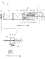
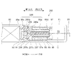
- FIG. 2 is a diagram showing an example of a schematic configuration of the vehicle height adjusting device 100 according to the first embodiment.
- the motorcycle 1 as an example of a saddle-mounted vehicle includes a front wheel 2 which is a front wheel and a rear wheel 3 which is a rear wheel. Further, the motorcycle 1 includes a vehicle body frame 11 forming the skeleton of the motorcycle 1, a steering wheel 12, a brake lever 13, and a vehicle body 10 having a seat 14.
- the front wheels 2 and the rear wheels 3 may be collectively referred to as "wheels 4".
- the motorcycle 1 has one front fork 21 as an example of the first suspension device for connecting the front wheel 2 and the vehicle body 10, one on the left side and one on the right side of the front wheel 2.
- the motorcycle 1 includes two brackets 15 for holding two front forks 21 arranged on the left and right sides of the front wheel 2, and a shaft 16 arranged between the two brackets 15.
- the shaft 16 is rotatably supported by the vehicle body frame 11.
- the front fork 21 includes a suspension spring 21s as an example of a spring that absorbs an impact applied to the front wheel 2 from a road surface or the like, and a damping device 21d that attenuates the vibration of the suspension spring 21s.
- the motorcycle 1 has one rear suspension 22 as an example of the second suspension device for connecting the rear wheel 3 and the vehicle main body 10, one on the left side and one on the right side of the rear wheel 3.
- the rear suspension 22 includes a suspension spring 22s as an example of a spring that absorbs an impact applied to the rear wheel 3 from a road surface or the like, and a damping device 22d that attenuates the vibration of the suspension spring 22s.
- the front fork 21 and the rear suspension 22 may be collectively referred to as a "suspension device 23".
- the suspended spring 21s and the suspended spring 22s may be collectively referred to as "spring 23s”.
- the motorcycle 1 has an adjusting unit 70 as an example of a vehicle height adjusting device for adjusting the height of the vehicle body 10, in other words, the vehicle height by changing the initial load (preload) applied to the spring 23s. I have.
- the adjusting unit 70 is provided in the suspension device 23, and includes a jack unit 71 as an example of a changing unit that changes the length of the spring 23s, and a supply device 80 that supplies oil to the jack chamber 72 of the jack unit 71.
- the jack portion 71 includes a support member 73 that supports the end portion of the spring 23s on the vehicle body 10 side, and a forming member 74 that forms the jack chamber 72 together with the support member 73. Then, the jack portion 71 adjusts the length of the spring 23s by moving the support member 73 according to the amount of oil in the jack chamber 72.
- the support member 73, the jack chamber 72, and the forming member 74 are each realized by the support member, the jack chamber, and the hydraulic jack of the rear suspension or the front fork described in Japanese Patent Application Laid-Open No. 2018-144650 filed by the present applicant. Can be exemplified.
- the jack portion 71 is provided with a movement amount sensor 75 that detects the movement amount of the support member 73.
- the movement amount of the support member 73 detected by the movement amount sensor 75 is the movement amount when the movement amount when the support member 73 is located at the reference position is 0.
- the reference position is the position of the support member 73 when the oil in the jack chamber 72 is 0.
- the supply device 80 includes a housing 81 for storing oil and a cylindrical piston 82 that slides in the housing 81.
- a storage chamber 83 for storing oil is formed on the inner surface of the housing 81 and in the space surrounded by the piston 82.
- the supply device 80 includes a motor 84, a speed reducer 85 that reduces the rotational speed of the motor 84, a screw 86 connected to the output shaft 85a of the speed reducer 85, and a control device 50 that controls the operation of the motor 84. It is equipped with.
- the motor 84 is a direct current (DC) motor with a brush.
- the speed reducer 85 is a planetary speed reducer using a well-known planetary gear mechanism.
- the control device 50 will be described in detail later.
- the screw 86 has three columnar parts having different diameters, the first part 86a, the second part 86b, and the third part 86c, on one side in the axial direction of the rotation axis C of the screw 86 (right side in FIG. 2). , The storage chamber 83 side) to the other side (left side in FIG. 2, speed reducer 85 side).
- the outer diameter of the second part 86b is larger than the outer diameter of the first part 86a and the outer diameter of the third part 86c.
- a male screw 86d is formed on the outer peripheral surface of the first portion 86a.
- the output shaft 85a of the speed reducer 85 is fitted inside the third part 86c. As a result, the screw 86 rotates integrally with the output shaft 85a of the speed reducer 85.
- the axial direction of the rotation axis C may be simply referred to as "axial direction”.
- the supply device 80 has a nut 87 formed with a female screw 87a that meshes with a male screw 86d formed in the first portion 86a of the screw 86.
- the nut 87 has a flange 87b at the end on the speed reducer 85 side.
- the supply device 80 includes an intervening member 88 interposed between the flange 87b of the nut 87 and the piston 82, and a cylindrical collar 89 arranged inside the intervening member 88 and outside the nut 87. It has a cylindrical collar 90 arranged on the outside of the intervening member 88.
- the intervening member 88 is an elastic member, and is sandwiched between the piston 82 and the flange 87b of the nut 87 in a state of being elastically deformed by being pressed by the piston 82 that receives a force from oil. As a result, the intervening member 88 suppresses the rotation of the nut 87 as the screw 86 rotates.
- the supply device 80 has a bearing 91 that rotatably supports the screw 86, a support member 92 that supports the bearing 91, and a hose 93 that allows oil to flow between the storage chamber 83 and the jack chamber 72. ing.
- the bearing 91 is arranged between the support member 92 and the second portion 86b of the screw 86.
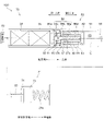
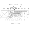
- FIG. 3 is a diagram showing an example of a state in which the flange 87b of the nut 87 and the second portion 86b of the screw 86 are in contact with each other.
- the first direction in the axial direction corresponds to the other side
- the second direction in the axial direction corresponds to one side.
- the shaft of the motor 84 of the supply device 80 rotates in the first rotation direction, so that the screw 86 rotates in the first rotation direction and the nut 87 rotates in the first rotation direction. Move in one direction. Then, the piston 82 that receives the force of the oil in the storage chamber 83 moves in the first axial direction.
- the support member 73 discharges the oil in the jack chamber 72 and supplies it to the storage chamber 83.
- the support member 73 moves to the vehicle body 10 side (left side in FIG. 3) with respect to the forming member 74, in other words, the amount of movement of the support member 73 from the reference position becomes small, and the spring length of the spring 23s becomes long. become longer.
- the spring length of the spring 23s becomes long, the initial load becomes small and the height of the vehicle body 10 decreases (the vehicle height becomes low).
- the supply device 80 has a contact portion 95 which is a portion where the flange 87b of the nut 87 and the second portion 86b of the screw 86 come into contact with each other at a position different from the fitting portion between the male screw 86d and the female screw 87a. As a result, the movement of the nut 87 in the first direction is stopped.
- the nut 87 moves in the second axial direction due to the rotation of the shaft of the motor 84 in the second rotational direction, whereby the nut 87 The flange 87b and the second portion 86b of the screw 86 do not come into contact with each other.
- the supply device 80 does not have the contact portion 95, for example, as shown in FIG.
- the intervening member 88, the collar 89, and the collar 90 interposed between the flange 87b of the nut 87 and the piston 82 move the piston 82 in the second direction as the nut 87 moves in the second direction. And suppresses the rotation of the nut 87 according to the rotation of the screw 86.
- the present invention is not particularly limited to this aspect. For example, when the portion of the nut 87 on the storage chamber 83 side comes into contact with the piston 82, the piston 82 may be moved in the second direction according to the movement of the nut 87 in the second direction.
- a spherical member is fitted into the recess formed in the member arranged between the nut 87 and the housing 81 and the recess formed in the portion of the nut 87 facing the recess. You may suppress the rotation of the nut 87 according to the rotation of the screw 86.
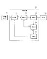
- FIG. 4 is a diagram showing an example of a block diagram of the control device 50.
- the control device 50 includes a CPU, a ROM in which programs executed by the CPU, various data, and the like are stored, a RAM used as a working memory of the CPU, and an EEPROM which is a non-volatile memory. An output signal from the movement amount sensor 75 or the like is input to the control device 50.
- the control device 50 includes a setting unit 51 for setting a target current It to be supplied to the motor 84, a control unit 52 for controlling the drive of the motor 84, and a drive unit 53 for driving the motor 84. Further, the control device 50 uses the detection unit 54 for detecting the motor current Im actually flowing in the motor 84 and the motor current Im detected by the detection unit 54 to use the flange 87b of the nut 87 and the second part 86b of the screw 86. It is provided with a determination unit 60 for determining the presence / absence of a contact portion 95, which is a portion where the contact is made.
- the processing by the setting unit 51, the control unit 52, and the determination unit 60 is realized by the CPU executing software stored in a storage area such as a ROM.
- the control unit 52 performs feedback control so that the deviation between the target current It set by the setting unit 51 and the motor current Im detected by the detection unit 54 becomes zero.
- the drive unit 53 has, for example, a transistor (FET) as a switching element connected between the positive electrode side line of the power supply and the coil of the motor 84. Then, the drive unit 53 controls the drive of the motor 84 by driving the gate of the transistor and switching the transistor.
- the detection unit 54 detects the motor current Im flowing through the motor 84 from the voltage generated across the shunt resistance connected to the drive unit 53.
- the setting unit 51 sets a target current It for moving the piston 82 so that the target value Lt of the movement amount of the support member 73 and the detection value La grasped by using the output value of the movement amount sensor 75 match.
- the target value Lt is a value corresponding to the target vehicle height selected by the user via the user interface provided in the motorcycle 1.
- the setting unit 51 moves the piston 82 in the second axial direction, which is the direction in which the oil is discharged from the storage chamber 83
- the setting unit 51 sets the target current It to a predetermined first position in order to raise the vehicle height. Set to the value of.
- the setting unit 51 is predetermined to lower the target current It and the vehicle height. Set to the second value.
- the current in the direction of rotating the motor 84 so as to move the piston 82 in the second axial direction is added, and the current in the direction of rotating the motor 84 so as to move the piston 82 in the first axial direction is added.
- the first value is 8A and the second value is -8A.
- the movement amount of the support member 73 is less than the target value Lt, so that the setting unit 51 moves the piston 82 in the second axial direction by the target current. It is set to the first value.
- the subtraction value ⁇ L is smaller than 0 ( ⁇ L ⁇ 0)
- the support member 73 is moving beyond the target value Lt, so that the setting unit 51 moves the piston 82 in the first direction in the axial direction.
- the target current It is set to the second value.
- the first period can be exemplified as, for example, one second. However, the first period may be 0.
- the second period is a period sufficient to eliminate the state in which the flange 87b of the nut 87 and the second part 86b of the screw 86 are in contact with each other by setting the target current It to a third value, for example, 2 It can be exemplified that it is a second. It can be exemplified that the third value is 8A like the first value.
- the determination unit 60 determines the presence / absence of the contact portion 95 by using the value of the current supplied to the motor 84. More specifically, the determination unit 60 sets a predetermined threshold value for the motor current Im detected by the detection unit 54 when the target current It is set to a second value (for example, -8A). When the period below the standard period exceeds a predetermined reference period, it is determined that the contact portion 95 is provided. On the other hand, even if the motor current Im is below the threshold value, the determination unit 60 determines that the contact unit 95 is not provided if the period during which the motor current Im is below the threshold value does not exceed the reference period. It can be exemplified that the threshold value is -10A and the reference period is 300 milliseconds.
- FIG. 5 is a flowchart showing an example of a procedure for setting the target current It performed by the setting unit 51.
- the setting unit 51 repeatedly executes this process, for example, in a predetermined control cycle (for example, every 1 millisecond).
- the setting unit 51 determines whether or not the target current It is 0 (S501). When the target current It is not 0 (No in S501), the setting unit 51 ends this process.
- the absolute value of the subtraction value ⁇ L is equal to or less than the reference value (Yes in S502), the setting unit 51 ends this process.
- the setting unit 51 sets the target current It to the first value in order to move the piston 82 in the second axial direction (S504).
- the setting unit 51 sets the target current It to the second value in order to move the piston 82 in the first axial direction (S505). ..
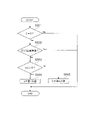
- FIG. 6 is a flowchart showing an example of a procedure for setting the target current It performed by the setting unit 51.
- the setting unit 51 repeatedly executes this process, for example, in a predetermined control cycle (for example, every 1 millisecond).
- the setting unit 51 determines whether or not the target current It is the second value (S601). When the target current It is not the second value (No in S601), the setting unit 51 ends this process.
- the setting unit 51 determines whether or not the absolute value of the subtraction value ⁇ L is equal to or less than the reference value (S602).
- the setting unit 51 sets the target current It to 0 (S603).
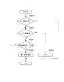
- the setting unit 51 determines whether or not the determination unit 60 has determined to have the contact unit 95 (S604). When it is not determined that the determination unit 60 has the contact unit 95 (No in S604), the setting unit 51 performs the processing after S602. On the other hand, when it is determined that the determination unit 60 has the contact unit 95 (Yes in S604), the setting unit 51 performs return control (S605).
- the vehicle height adjusting device 100 configured as described above can adjust the vehicle height by supplying power to the motor 84 and the control device 50 from the battery (not shown) when the power of the motorcycle 1 is turned on. On the other hand, when the power of the motorcycle 1 is turned off, the power supply from the battery to the motor 84 and the control device 50 is stopped, and the vehicle height cannot be adjusted.
- the supply device 80 includes a motor 84, a speed reducer 85 connected to the rotation shaft of the motor 84, a screw 86 connected to the speed reducer 85, and a screw 86 fitted to the screw 86 and rotated as the screw 86 rotates.
- a fluid supply device including a nut 87 as an example of a nut member that moves in the axial direction of the shaft C.
- the supply device 80 is an example of a piston 82 that is movable in the axial direction due to the movement of the nut 87 in the axial direction and a fluid whose capacity is increased or decreased by the movement of the piston 82 in the axial direction.
- the fluid is not limited to oil.
- the fluid may be air.
- the control device 50 has a determination unit 60 for determining the presence or absence of a contact portion 95, which is a portion where the screw 86 and the nut 87 come into contact with each other at a portion different from the male screw 86d and the female screw 87a as an example of the fitted portion. Then, when the control device 50 determines that the determination unit 60 has the contact portion 95 when the motor 84 is energized to move the nut 87 in the first direction, the control device 50 does not have the contact portion 95.
- the motor 84 is energized to move the nut 87 in the second direction opposite to the first direction.
- the control method of the motor 84 performed by the control device 50 includes a determination step (S604) for determining the presence or absence of the contact portion 95 when the motor 84 is energized to move the nut 87 in the first direction. .. Further, in the control method of the motor 84 performed by the control device 50, when it is determined in the determination step that the motor 84 has the contact portion 95, the nut 87 is in the direction opposite to the first direction until the contact portion 95 is no longer present. It has a return step (S605) in which the motor 84 is energized so as to be moved in two directions.
- the absolute value of the subtraction value ⁇ L is larger than the reference value and the subtraction value ⁇ L is smaller than 0 due to the reduction of the target value Lt.
- the target current It is set to the second value.
- the shaft of the motor 84 rotates in the first rotation direction, and the nut 87 moves in the first direction in the axial direction.
- the setting unit 51 sets the target current It to 0 and stops the driving of the motor 84.
- the motor 84 is driven. Do not stop.
- the determination unit 60 determines that the contact unit 95 is possessed, the setting unit 51 performs return control. As a result, the nut 87 moves in the second direction until it no longer has the contact portion 95.
- the control device according to the comparative example is a control device that stops energization and does not perform return control.
- the energization to the motor 84 is stopped in a state where the flange 87b of the nut 87 and the second portion 86b of the screw 86 are in contact with each other.
- the gear of the speed reducer 85 interposed between the motor 84 and the screw 86 rotates in the reverse direction by the amount of backlash and stops. Then, for example, when the power of the motorcycle 1 is turned off in this state and then the power of the motorcycle 1 is turned on again, in the control device according to the comparative example, for example, the movement amount sensor 75 is out of order. In this case, the shaft of the motor 84 is rotated in the first rotation direction so that the actual movement amount of the support member 73 becomes the target value Lt. Then, after the motor 84 rotates in a no-load state and the rotation speed increases, there is a possibility that the gears of the speed reducer 85 mesh with each other.
- the screw 86 does not rotate and a large load is applied to the gear of the speed reducer 85.
- the speed reducer 85 has multiple stages
- the reducer (hereinafter, may be referred to as "front-rear speed reducer”) that is closer to the motor 84 than the last-stage reducer rotates until the gap is filled and the teeth come into contact with each other.
- the durability of the gear teeth of the previous stage reducer May decrease.
- the screw 86 is further rotated after the teeth of the gears of the final speed reducer come into contact with each other, and the nut 87 is used. The contact pressure between the nut 87 and the screw 86 increases, and the nut 87 or the screw 86 may wear, resulting in a decrease in durability.
- control device 50 performs return control to energize the motor 84 in a state where the flange 87b of the nut 87 and the second portion 86b of the screw 86 are not in contact with each other. Stop. Therefore, after the power of the motorcycle 1 is turned off in this state, the power of the motorcycle 1 is turned on again, and the shaft of the motor 84 is set so that the actual movement amount of the support member 73 becomes the target value Lt. Is rotated in the first rotation direction, the nut 87 moves in the first rotation direction.
- the impact force generated on the gear teeth of the speed reducer 85 becomes smaller as the rotation of the speed reducer 85 stops, so that the durability of the gear teeth of the speed reducer 85 is suppressed from being lowered.
- the flange 87b of the nut 87 and the second portion 86b of the screw 86 are in contact with each other, the power of the motorcycle 1 is turned on and the shaft of the motor 84 rotates in the first rotation direction. Since it is suppressed that the contact pressure with the screw 86 is further increased, it is suppressed that the nut 87 or the screw 86 is worn and the durability is lowered.
- FIG. 7 is a diagram showing an example of a schematic configuration of the supply device 280 according to the second embodiment.
- the supply device 280 according to the second embodiment has different shapes of the screw 86 and the nut 87 from the supply device 80 according to the first embodiment.
- the points different from the first embodiment will be described.
- the same reference numerals are used for the same ones, and detailed description thereof will be omitted.
- the screw 286 according to the second embodiment has a first part 86a, a second part 286b, and a third part 86c.
- the nut 287 according to the second embodiment has a flange 287b at the end on the speed reducer 85 side.
- the surface 286e of the second portion 286b facing the flange 287b extends in a direction intersecting the rotation axis C.
- the surface 287c of the flange 287b facing the second portion 286b extends in a direction intersecting the rotation axis C.
- the angle formed by the surface 286e of the second portion 286b and the rotating shaft C and the angle formed by the surface 287c of the flange 287b and the rotating shaft C are the same angle.
- the movement of the nut 287 with respect to the screw 286 is suppressed by the contact of the surface 287c of the nut 287 with the surface 286e of the screw 286.
- the supply device 280 has a contact portion 295 which is a portion where the surface 287c of the nut 287 and the surface 286e of the screw 286 come into contact with each other, so that the movement of the nut 287 in the first direction is stopped.
- the contact portion 295 is provided on the screw 286 and is provided on the nut 287 and extends so as to face the surface 286e as an example of the first surface extending in the direction intersecting the rotation axis C.
- a surface 287c is provided as an example of the second surface.
- FIG. 8 is a diagram showing an example of a schematic configuration of the supply device 380 according to the third embodiment.
- the supply device 380 according to the third embodiment is different from the supply device 80 according to the first embodiment in that an elastic member 96 is provided between the screw 86 and the nut 87.
- an elastic member 96 is provided between the screw 86 and the nut 87.
- the elastic member 96 is a disk-shaped member having a through hole formed in the central portion through which the first portion 86a of the screw 86 is passed. It can be exemplified that the material of the elastic member 96 is a resin such as polyurethane.
- the supply device 380 when the shaft of the motor 84 continues to rotate in the first rotation direction, the flange 87b of the nut 87 comes into contact with the elastic member 96 and is elastic. When the member 96 comes into contact with the second portion 86b of the screw 86, the movement of the nut 87 in the first direction is stopped.
- the supply device 380 includes an elastic member 96 having elasticity in the axial direction, and has a contact portion 395 in which the screw 86 and the nut 87 come into contact with each other via the elastic member 96, whereby the first direction of the nut 87 is obtained. The movement of is stopped.
- the rotation speed of the screw 86 is suppressed by the nut 87 coming into contact with the elastic member 96, so that the impact force generated on the gear teeth of the speed reducer 85 when the rotation of the screw 86 is stopped becomes small. .. As a result, it becomes easy to improve the durability of the gear of the speed reducer 85.
- An elastic member corresponding to the elastic member 96 is provided between the surface 286e of the screw 286 and the surface 287c of the nut 287 according to the second embodiment, and the screw 286 and the nut 287 are connected via the elastic member. You may make contact.
- the control device of the supply device according to the fourth embodiment has a different current value setting from the control devices of the supply devices 80, 280, and 380 according to the first, second, and third embodiments.
- the points different from the first embodiment will be described.
- the same reference numerals are used for the same ones, and detailed description thereof will be omitted.
- the control device is more than the absolute value of the third value as an example of the first current value supplied to the motor 84 when the nut 87 is moved in the second direction during the return control.
- the absolute value of the second value as an example of the second current value supplied to the motor 84 when the nut 87 is moved in the first direction is reduced.
- the second value is -4A and the third value is 8A.
- the first value may be 4A, which is smaller than the third value, or may be 8A, which is the same as the third value.
- the second value is -8A and the third value is 12A.
- the first value may be 8A, which is smaller than the third value, or 12A, which is the same as the third value.
- the absolute value of the target current It (second value) for moving the nut 87 in the first direction is set to the target current It (second value) for moving the nut 87 in the second direction during return control.
- the absolute value (value of 3) it is possible to suppress the rotation speed of the motor 84 when the nut 87 hits the screw 86.
- the impact force generated on the gear teeth of the speed reducer 85 when the nut 87 hits the screw 86 is reduced, so that the durability of the gear teeth of the speed reducer 85 can be easily improved.
- the contact pressure between the nut 87 and the screw 86 when the nut 87 hits the screw 86 becomes small, the durability of the nut 87 or the screw 86 can be easily improved.
- a motorcycle is exemplified as a saddle-mounted vehicle, but the form of the saddle-mounted vehicle of the present invention is not limited to this.
- the saddle-mounted vehicle of the present invention may be a vehicle in which the occupant straddles the seat, and the number of wheels thereof can be any number of 2 or more.
Landscapes
- Engineering & Computer Science (AREA)
- Mechanical Engineering (AREA)
- Power Engineering (AREA)
- General Engineering & Computer Science (AREA)
- Vehicle Body Suspensions (AREA)
- Transmission Devices (AREA)
Abstract
Description
例えば、特許文献1に記載された車高調整装置は、以下のように構成されている。すなわち、ジャッキ室へ作動流体を給排するポンプは、シリンダと、シリンダ内に摺動自在に挿入されるピストンで区画されるとともにジャッキ室へ連通されるポンプ室と、ピストンをシリンダに対して軸方向に駆動する駆動手段とを備える。駆動手段は、ピストンの反ポンプ室側に配置されてピストンを反ポンプ室側から支持するナットと、筒状であってシリンダに対して回り止めされつつナットの外周に摺接してナットのシリンダに対する回転を阻止して軸方向の移動のみを許容する樹脂製のガイド部材とを備える。また、駆動手段は、先端側がナット内に螺合され基端が駆動源に連結されて回転駆動されるとともに中間にガイド部材の反ピストン側の端部に摺接する摺接部を備えた螺子軸とを備える。
本発明は、流体を供給する装置を構成する部品の耐久性を向上させることができるモータの制御方法等を提供することを目的とする。
ここで、前記判断工程は、前記モータに供給される電流の値を用いて、前記接触部の有無を判断しても良い。
本開示の他の態様は、モータと、前記モータの回転軸に連結された減速機と、前記減速機に連結されたスクリューと、前記スクリューにはめ合わされて前記スクリューの回転に伴い前記スクリューの回転軸の軸方向へ移動するナット部材と、前記ナット部材が前記軸方向へと移動することに起因して前記軸方向に移動可能なピストンと、前記ピストンが前記軸方向へと移動することにより収容量が増減する流体を貯留する貯留室と、前記モータの動作を制御する制御装置と、を備え、前記制御装置は、はめ合わされている部位とは異なる箇所で前記スクリューと前記ナット部材とが接触する部位である接触部の有無を判断する判断部を有し、前記ナット部材を第1方向に移動させるべく前記モータに通電しているときに、前記判断部が前記接触部を有すると判断した場合に、前記接触部を有しなくなるまで前記ナット部材を前記第1方向とは逆方向である第2方向に移動させるべく前記モータに通電する、流体供給装置である。
ここで、前記判断部は、前記モータに供給される電流の値を用いて、前記接触部の有無を判断しても良い。
また、前記接触部は、前記スクリューに備えられるとともに前記回転軸と交差する方向に延びた第1面と、前記ナット部材に備えられるとともに前記第1面と対向するように延びた第2面とを備えても良い。
また、前記接触部は、前記軸方向に弾性を有する弾性部材を備え、前記弾性部材を介して、前記スクリューと前記ナット部材とが接触しても良い。
また、前記制御装置は、前記接触部を有しなくなるまで前記ナット部材を前記第2方向に移動させる際に前記モータに供給する第1電流値の絶対値よりも、前記ナット部材を前記第1方向に移動させる際に前記モータに供給する第2電流値の絶対値を小さくしても良い。
本開示の他の態様は、上記した態様に係る流体供給装置と、前記流体供給装置にて供給される流体を用いて、車両本体と車輪との間に配置される懸架装置のばねの長さを変更する変更部と、を備える車高調整装置である。
本開示の他の態様は、車両本体と、前記車両本体の前側に配置される前輪、及び、前記車両本体の後側に配置される後輪と、前記車両本体と前記前輪との間に配置される第1懸架装置と、前記車両本体と前記後輪との間に配置される、ばねを有する第2懸架装置と、上記した態様に係る流体供給装置によって供給される流体を用いて、前記第2懸架装置における前記ばねの荷重を調整可能な車高調整装置と、を備える鞍乗型車両である。
図1は、第1の実施形態に係る自動二輪車1の概略構成の一例を示す図である。
図2は、第1の実施形態に係る車高調整装置100の概略構成の一例を示す図である。
鞍乗型車両の一例としての自動二輪車1は、前側の車輪である前輪2と、後側の車輪である後輪3とを備えている。また、自動二輪車1は、自動二輪車1の骨格をなす車体フレーム11と、ハンドル12と、ブレーキレバー13と、シート14とを有する車両本体10を備えている。以下の説明において、前輪2と後輪3とをまとめて「車輪4」と称する場合もある。
なお、以下の説明において、フロントフォーク21とリヤサスペンション22とをまとめて「懸架装置23」と称する場合もある。また、懸架スプリング21sと懸架スプリング22sとをまとめて「スプリング23s」と称する場合もある。
調整部70は、懸架装置23に設けられて、スプリング23sの長さを変更する変更部の一例としてのジャッキ部71と、ジャッキ部71のジャッキ室72にオイルを供給する供給装置80とを備えている。
ジャッキ部71は、図2に示すように、スプリング23sの車両本体10側の端部を支持する支持部材73と、支持部材73とともにジャッキ室72を形成する形成部材74とを備えている。そして、ジャッキ部71は、ジャッキ室72内のオイルの量に応じて支持部材73が移動することで、スプリング23sの長さを調整する。支持部材73、ジャッキ室72、形成部材74は、それぞれ、本出願人が出願した特開2018-144650号公報に記載されたリヤサスペンション又はフロントフォークの支持部材、ジャッキ室、油圧ジャッキにて実現されることを例示することができる。
また、供給装置80は、モータ84と、モータ84の回転速度を減速させる減速機85と、減速機85の出力軸85aに連結されたスクリュー86と、モータ84の動作を制御する制御装置50とを備えている。
スクリュー86は、それぞれ径が異なる3つの円柱状の部位である、第1部86a、第2部86b、第3部86cを、スクリュー86の回転軸Cの軸方向の一方側(図2では右側、貯留室83側)から他方側(図2では左側、減速機85側)にかけて順に有する。第2部86bの外径は、第1部86aの外径及び第3部86cの外径よりも大きい。第1部86aの外周面に、雄ねじ86dが形成されている。第3部86cの内側には、減速機85の出力軸85aが嵌め込まれている。これにより、スクリュー86は、減速機85の出力軸85aと一体的に回転する。以下の説明において、回転軸Cの軸方向を、単に「軸方向」と称する場合もある。
また、供給装置80は、ナット87のフランジ87bと、ピストン82との間に介在する介在部材88と、介在部材88の内側であってナット87の外側に配置された円筒状のカラー89と、介在部材88の外側に配置された円筒状のカラー90とを有している。介在部材88は、弾性部材であり、オイルから力を受けたピストン82により加圧されることにより弾性変形した状態で、ピストン82とナット87のフランジ87bとの間に挟み込まれている。これにより、介在部材88は、スクリュー86の回転に従って、ナット87が回転することを抑制する。
以上のように構成された調整部70においては、供給装置80のモータ84の軸が第1回転方向に回転することにより、スクリュー86が第1回転方向に回転し、ナット87が軸方向の第1方向に移動する。すると、貯留室83のオイルの力を受けるピストン82が軸方向の第1方向に移動する。ピストン82の第1方向への移動に伴い、貯留室83の容積が大きくなる。これにより、支持部材73がジャッキ室72内のオイルを排出し、これを貯留室83に供給する。その結果、支持部材73が形成部材74に対して車両本体10側(図3では左側)に移動し、言い換えれば、支持部材73の基準位置からの移動量が小さくなり、スプリング23sのばね長が長くなる。スプリング23sのばね長が長くなると、初期荷重が小さくなり、車両本体10の高さが下降する(車高が低くなる)。
例えば、図3に示した接触部95を有する状態から、モータ84の軸が第2回転方向に回転することに起因してナット87が軸方向の第2方向に移動することにより、ナット87のフランジ87bとスクリュー86の第2部86bとが接触しなくなる。これにより、供給装置80は、例えば図2に示すように、接触部95を有しなくなる。
次に、制御装置50について説明する。
図4は、制御装置50のブロック図の一例を示す図である。
制御装置50は、CPUと、CPUにて実行されるプログラムや各種データ等が記憶されたROMと、CPUの作業用メモリ等として用いられるRAMと、不揮発性メモリであるEEPROMとを備えている。制御装置50には、移動量センサ75等からの出力信号が入力される。
駆動部53は、例えば、電源の正極側ラインとモータ84のコイルとの間に接続された、スイッチング素子としてのトランジスタ(FET)を有している。そして、駆動部53は、このトランジスタのゲートを駆動してこのトランジスタをスイッチング動作させることにより、モータ84の駆動を制御する。
検出部54は、駆動部53に接続されたシャント抵抗の両端に生じる電圧から、モータ84に流れるモータ電流Imを検出する。
設定部51は、支持部材73の移動量の目標値Ltと、移動量センサ75の出力値を用いて把握した検出値Laとが一致するように、ピストン82を移動させるための目標電流Itを設定する。目標値Ltは、自動二輪車1に設けられたユーザインターフェースを介してユーザにより選択された目標車高に応じた値であることを例示することができる。
戻し制御として、設定部51は、以下に述べる目標電流Itの設定処理を行う。すなわち、先ず、設定部51は、モータ84への通電を停止する(It=0)。そして、設定部51は、通電停止後に予め定められた第1期間が経過したときに、目標電流Itを第3の値に設定する。そして、設定部51は、目標電流Itを第3の値に設定した後に予め定められた第2期間が経過したときに通電を停止する。
判断部60は、モータ84へと供給される電流の値を用いて、接触部95の有無を判断する。より具体的には、判断部60は、目標電流Itが第2の値(例えば-8A)に設定されているときに、検出部54にて検出されたモータ電流Imが予め定められた閾値を下回る期間が予め定められた基準期間を超えた場合に、接触部95を有すると判断する。他方、判断部60は、モータ電流Imが閾値を下回っていたとしても、下回っていた期間が基準期間を超えていない場合には接触部95を有しないと判断する。なお、閾値は-10A、基準期間は300ミリ秒であることを例示することができる。
設定部51は、この処理を、例えば予め定めた制御周期にて(例えば1ミリ秒毎に)繰り返し実行する。
設定部51は、先ず、目標電流Itが0であるか否かを判断する(S501)。目標電流Itが0ではない場合(S501でNo)、設定部51は、本処理を終了する。他方、目標電流Itが0である場合(S501でYes)、設定部51は、減算値ΔL(=Lt-La)の絶対値が基準値以下であるか否かを判断する(S502)。減算値ΔLの絶対値が基準値以下である場合(S502でYes)、設定部51は、本処理を終了する。
設定部51は、この処理を、例えば予め定めた制御周期にて(例えば1ミリ秒毎に)繰り返し実行する。
設定部51は、先ず、目標電流Itが第2の値であるか否かを判断する(S601)。目標電流Itが第2の値ではない場合(S601でNo)、設定部51は、本処理を終了する。他方、目標電流Itが第2の値である場合(S601でYes)、設定部51は、減算値ΔLの絶対値が基準値以下であるか否かを判断する(S602)。減算値ΔLの絶対値が基準値以下である場合(S602でYes)、設定部51は、目標電流Itを0に設定する(S603)。
供給装置80は、モータ84と、モータ84の回転軸に連結された減速機85と、減速機85に連結されたスクリュー86と、スクリュー86にはめ合わされてスクリュー86の回転に伴いスクリュー86の回転軸Cの軸方向へ移動するナット部材の一例としてのナット87とを備える流体供給装置の一例である。また、供給装置80は、ナット87が軸方向へと移動することに起因して軸方向に移動可能なピストン82と、ピストン82が軸方向へと移動することにより収容量が増減する流体の一例としてのオイルを貯留する貯留室83と、モータ84の動作を制御する制御装置50とを備える。なお、流体はオイルに限定されない。流体は、空気であっても良い。制御装置50は、はめ合わされている部位の一例としての雄ねじ86d及び雌ねじ87aとは異なる箇所でスクリュー86とナット87とが接触する部位である接触部95の有無を判断する判断部60を有する。そして、制御装置50は、ナット87を第1方向に移動させるべくモータ84に通電しているときに、判断部60が接触部95を有すると判断した場合に、接触部95を有しなくなるまでナット87を第1方向とは逆方向である第2方向に移動させるべくモータ84に通電する。
図7は、第2の実施形態に係る供給装置280の概略構成の一例を示す図である。
第2の実施形態に係る供給装置280は、第1の実施形態に係る供給装置80に対して、スクリュー86とナット87の形状が異なる。以下、第1の実施形態と異なる点について説明する。第1の実施形態と第2の実施形態とで、同じものについては同じ符号を用い、その詳細な説明は省略する。
図8は、第3の実施形態に係る供給装置380の概略構成の一例を示す図である。
第3の実施形態に係る供給装置380は、第1の実施形態に係る供給装置80に対して、スクリュー86とナット87との間に弾性部材96を備える点が異なる。以下、第1の実施形態と異なる点について説明する。第1の実施形態と第3の実施形態とで、同じものについては同じ符号を用い、その詳細な説明は省略する。
第4の実施形態に係る供給装置の制御装置は、第1,第2,第3の実施形態に係る供給装置80,280,380の制御装置に対して、電流値の設定が異なる。以下、第1の実施形態と異なる点について説明する。第1の実施形態と第4の実施形態とで、同じものについては同じ符号を用い、その詳細な説明は省略する。
Claims (9)
- モータと、前記モータの出力軸に連結された減速機と、前記減速機に連結されたスクリューと、前記スクリューにはめ合わされて前記スクリューの回転に伴い前記スクリューの回転軸の軸方向へ移動するナット部材と、前記ナット部材が前記軸方向へと移動することに起因して前記軸方向に移動可能なピストンと、前記ピストンが前記軸方向へと移動することにより収容量が増減する流体を貯留する貯留室と、を有する流体供給装置における前記モータの動作を制御する際に、
前記ナット部材を第1方向に移動させるべく前記モータに通電しているときに、はめ合わされている部位とは異なる箇所で前記スクリューと前記ナット部材とが接触する部位である接触部の有無を判断する判断工程と、
前記判断工程で前記接触部を有すると判断した場合に、前記接触部を有しなくなるまで、前記ナット部材を前記第1方向とは逆方向である第2方向に移動させるべく前記モータに通電する戻し工程と、
を有するモータの制御方法。 - 前記判断工程は、前記モータに供給される電流の値を用いて、前記接触部の有無を判断する、
請求項1に記載のモータの制御方法。 - モータと、
前記モータの回転軸に連結された減速機と、
前記減速機に連結されたスクリューと、
前記スクリューにはめ合わされて前記スクリューの回転に伴い前記スクリューの回転軸の軸方向へ移動するナット部材と、
前記ナット部材が前記軸方向へと移動することに起因して前記軸方向に移動可能なピストンと、
前記ピストンが前記軸方向へと移動することにより収容量が増減する流体を貯留する貯留室と、
前記モータの動作を制御する制御装置と、
を備え、
前記制御装置は、
はめ合わされている部位とは異なる箇所で前記スクリューと前記ナット部材とが接触する部位である接触部の有無を判断する判断部を有し、前記ナット部材を第1方向に移動させるべく前記モータに通電しているときに、前記判断部が前記接触部を有すると判断した場合に、前記接触部を有しなくなるまで前記ナット部材を前記第1方向とは逆方向である第2方向に移動させるべく前記モータに通電する、
流体供給装置。 - 前記判断部は、前記モータに供給される電流の値を用いて、前記接触部の有無を判断する、
請求項3に記載の流体供給装置。 - 前記接触部は、前記スクリューに備えられるとともに前記回転軸と交差する方向に延びた第1面と、前記ナット部材に備えられるとともに前記第1面と対向するように延びた第2面とを備える、
請求項3または4に記載の流体供給装置。 - 前記接触部は、前記軸方向に弾性を有する弾性部材を備え、前記弾性部材を介して、前記スクリューと前記ナット部材とが接触する、
請求項3~5のいずれか1項に記載の流体供給装置。 - 前記制御装置は、前記接触部を有しなくなるまで前記ナット部材を前記第2方向に移動させる際に前記モータに供給する第1電流値の絶対値よりも、前記ナット部材を前記第1方向に移動させる際に前記モータに供給する第2電流値の絶対値を小さくする、
請求項3~6のいずれか1項に記載の流体供給装置。 - 請求項3から7のいずれか1項に記載の流体供給装置と、
前記流体供給装置にて供給される流体を用いて、車両本体と車輪との間に配置される懸架装置のばねの長さを変更する変更部と、
を備える車高調整装置。 - 車両本体と、
前記車両本体の前側に配置される前輪、及び、前記車両本体の後側に配置される後輪と、
前記車両本体と前記前輪との間に配置される第1懸架装置と、
前記車両本体と前記後輪との間に配置される、ばねを有する第2懸架装置と、
請求項3から7のいずれか1項に記載の流体供給装置によって供給される流体を用いて、前記第2懸架装置における前記ばねの荷重を調整可能な車高調整装置と、
を備える鞍乗型車両。
Priority Applications (5)
| Application Number | Priority Date | Filing Date | Title |
|---|---|---|---|
| DE112020007518.4T DE112020007518T5 (de) | 2020-11-26 | 2020-11-26 | Verfahren zur Motorsteuerung, Fluidzuführvorrichtung, Fahrzeughöheneinstellvorrichtung, und Fahrzeug des Sattelsitztyps |
| JP2020566312A JP6873366B1 (ja) | 2020-11-26 | 2020-11-26 | モータの制御方法、流体供給装置、車高調整装置、鞍乗型車両 |
| GB2305554.4A GB2615906B (en) | 2020-11-26 | 2020-11-26 | Motor control method, fluid supply device, vehicle height adjustment device, saddle-type vehicle |
| PCT/JP2020/044005 WO2022113231A1 (ja) | 2020-11-26 | 2020-11-26 | モータの制御方法、流体供給装置、車高調整装置、鞍乗型車両 |
| US18/299,391 US12552489B2 (en) | 2020-11-26 | 2023-04-12 | Motor control method, fluid supply device, vehicle height adjustment device, and saddle-type vehicle |
Applications Claiming Priority (1)
| Application Number | Priority Date | Filing Date | Title |
|---|---|---|---|
| PCT/JP2020/044005 WO2022113231A1 (ja) | 2020-11-26 | 2020-11-26 | モータの制御方法、流体供給装置、車高調整装置、鞍乗型車両 |
Related Child Applications (1)
| Application Number | Title | Priority Date | Filing Date |
|---|---|---|---|
| US18/299,391 Continuation US12552489B2 (en) | 2020-11-26 | 2023-04-12 | Motor control method, fluid supply device, vehicle height adjustment device, and saddle-type vehicle |
Publications (1)
| Publication Number | Publication Date |
|---|---|
| WO2022113231A1 true WO2022113231A1 (ja) | 2022-06-02 |
Family
ID=75896349
Family Applications (1)
| Application Number | Title | Priority Date | Filing Date |
|---|---|---|---|
| PCT/JP2020/044005 Ceased WO2022113231A1 (ja) | 2020-11-26 | 2020-11-26 | モータの制御方法、流体供給装置、車高調整装置、鞍乗型車両 |
Country Status (5)
| Country | Link |
|---|---|
| US (1) | US12552489B2 (ja) |
| JP (1) | JP6873366B1 (ja) |
| DE (1) | DE112020007518T5 (ja) |
| GB (1) | GB2615906B (ja) |
| WO (1) | WO2022113231A1 (ja) |
Citations (4)
| Publication number | Priority date | Publication date | Assignee | Title |
|---|---|---|---|---|
| JPH033687A (ja) * | 1989-05-31 | 1991-01-09 | Fanuc Ltd | サーボモータにより駆動される被駆動体の衝突破損防止方法 |
| JP2009096413A (ja) * | 2007-10-19 | 2009-05-07 | Mazda Motor Corp | 車両用懸架装置 |
| JP2009214836A (ja) * | 2008-03-12 | 2009-09-24 | Toyota Motor Corp | 電磁サスペンション |
| JP6789444B1 (ja) * | 2020-03-17 | 2020-11-25 | 株式会社ショーワ | モータ軸の状態検知方法、モータの制御方法、モータ軸の状態検知装置、モータの制御装置、車高調整装置、鞍乗型車両 |
Family Cites Families (8)
| Publication number | Priority date | Publication date | Assignee | Title |
|---|---|---|---|---|
| DE102007003902A1 (de) | 2007-01-19 | 2008-07-24 | Robert Bosch Gmbh | Kupplungssystem und Verfahren zur Steuerung eines Kupplungssystems |
| JP5275015B2 (ja) | 2008-12-24 | 2013-08-28 | カヤバ工業株式会社 | 車高調整装置 |
| WO2010074322A1 (ja) | 2008-12-24 | 2010-07-01 | カヤバ工業株式会社 | 車高調整装置 |
| JP5333046B2 (ja) | 2009-08-24 | 2013-11-06 | 株式会社島津製作所 | アクティブマトリックスアレイの製造方法 |
| JP6181335B1 (ja) | 2017-03-06 | 2017-08-16 | 株式会社ショーワ | 車高調整装置 |
| WO2021161408A1 (ja) * | 2020-02-12 | 2021-08-19 | 日立 Astemo 株式会社 | 処理装置、車高調整装置、鞍乗型車両 |
| EP4130514A4 (en) | 2020-03-23 | 2023-11-29 | Hitachi Astemo, Ltd. | FLUID FEEDING DEVICE, VEHICLE HEIGHT ADJUSTMENT DEVICE, SEMI-TRAIL VEHICLE |
| JP6873370B1 (ja) * | 2020-06-23 | 2021-05-19 | 日立Astemo株式会社 | 制御装置、懸架システム、鞍乗型車両 |
-
2020
- 2020-11-26 WO PCT/JP2020/044005 patent/WO2022113231A1/ja not_active Ceased
- 2020-11-26 DE DE112020007518.4T patent/DE112020007518T5/de active Pending
- 2020-11-26 GB GB2305554.4A patent/GB2615906B/en active Active
- 2020-11-26 JP JP2020566312A patent/JP6873366B1/ja active Active
-
2023
- 2023-04-12 US US18/299,391 patent/US12552489B2/en active Active
Patent Citations (4)
| Publication number | Priority date | Publication date | Assignee | Title |
|---|---|---|---|---|
| JPH033687A (ja) * | 1989-05-31 | 1991-01-09 | Fanuc Ltd | サーボモータにより駆動される被駆動体の衝突破損防止方法 |
| JP2009096413A (ja) * | 2007-10-19 | 2009-05-07 | Mazda Motor Corp | 車両用懸架装置 |
| JP2009214836A (ja) * | 2008-03-12 | 2009-09-24 | Toyota Motor Corp | 電磁サスペンション |
| JP6789444B1 (ja) * | 2020-03-17 | 2020-11-25 | 株式会社ショーワ | モータ軸の状態検知方法、モータの制御方法、モータ軸の状態検知装置、モータの制御装置、車高調整装置、鞍乗型車両 |
Also Published As
| Publication number | Publication date |
|---|---|
| GB2615906A (en) | 2023-08-23 |
| US20230242207A1 (en) | 2023-08-03 |
| GB202305554D0 (en) | 2023-05-31 |
| DE112020007518T5 (de) | 2023-09-14 |
| US12552489B2 (en) | 2026-02-17 |
| GB2615906B (en) | 2024-10-09 |
| JP6873366B1 (ja) | 2021-05-19 |
| JPWO2022113231A1 (ja) | 2022-06-02 |
Similar Documents
| Publication | Publication Date | Title |
|---|---|---|
| US9421843B2 (en) | Active suspension apparatus for vehicle and pump applied thereto | |
| JP2016092891A (ja) | 伸縮アクチュエータの制御方法、伸縮アクチュエータ及び転舵装置 | |
| KR20120090838A (ko) | 가변 용량형 펌프 | |
| JP6873366B1 (ja) | モータの制御方法、流体供給装置、車高調整装置、鞍乗型車両 | |
| JP6738510B1 (ja) | 流体供給装置、車高調整装置、鞍乗型車両 | |
| JP4594333B2 (ja) | 可変容量形ポンプ | |
| JP2004155418A (ja) | 車速感応型パワーステアリングシステム | |
| US12017496B2 (en) | Motor shaft state detection method, motor control method, motor shaft state detection device, motor control device, vehicle height adjustment device, saddle-type vehicle | |
| JP6799721B1 (ja) | 制御システム、鞍乗型車両 | |
| CN115384459A (zh) | 马达驱动的鼓式制动系统及控制其的方法 | |
| JP6789454B1 (ja) | 制御装置、車高調整装置、鞍乗型車両 | |
| JP7213172B2 (ja) | 車高調整装置 | |
| US8490742B2 (en) | Hydraulic power steering unit | |
| JP4530265B2 (ja) | 産業車両のステアリング装置 | |
| JP4442556B2 (ja) | 車高調整装置および液圧源制御装置 | |
| JP4103395B2 (ja) | ポンプ装置 | |
| JP3909832B2 (ja) | ラックピニオン型動力舵取装置 | |
| JP2016007968A (ja) | 電動倍力装置 | |
| JP2013082359A (ja) | 後輪転舵装置の中立位置復帰装置 | |
| JP4622658B2 (ja) | パワーステアリング装置 | |
| JP4631377B2 (ja) | 液圧ブレーキシステム | |
| JP2008057544A (ja) | ポンプ装置 | |
| JP4802738B2 (ja) | パワーステアリング装置 | |
| JP2008094351A (ja) | パワーステアリング装置 | |
| JP2677093B2 (ja) | 制動力制御装置 |
Legal Events
| Date | Code | Title | Description |
|---|---|---|---|
| ENP | Entry into the national phase |
Ref document number: 2020566312 Country of ref document: JP Kind code of ref document: A |
|
| 121 | Ep: the epo has been informed by wipo that ep was designated in this application |
Ref document number: 20963496 Country of ref document: EP Kind code of ref document: A1 |
|
| ENP | Entry into the national phase |
Ref document number: 202305554 Country of ref document: GB Kind code of ref document: A Free format text: PCT FILING DATE = 20201126 |
|
| WWE | Wipo information: entry into national phase |
Ref document number: 112020007518 Country of ref document: DE Ref document number: 2305554.4 Country of ref document: GB |
|
| WWP | Wipo information: published in national office |
Ref document number: 2305554.4 Country of ref document: GB |
|
| 122 | Ep: pct application non-entry in european phase |
Ref document number: 20963496 Country of ref document: EP Kind code of ref document: A1 |
|
| WWG | Wipo information: grant in national office |
Ref document number: 2305554.4 Country of ref document: GB |