WO2022080083A1 - 電気化学素子用電極活物質およびその製造方法、電気化学素子用電極材料、電気化学素子用電極、電気化学素子、並びに移動体 - Google Patents
電気化学素子用電極活物質およびその製造方法、電気化学素子用電極材料、電気化学素子用電極、電気化学素子、並びに移動体 Download PDFInfo
- Publication number
- WO2022080083A1 WO2022080083A1 PCT/JP2021/034246 JP2021034246W WO2022080083A1 WO 2022080083 A1 WO2022080083 A1 WO 2022080083A1 JP 2021034246 W JP2021034246 W JP 2021034246W WO 2022080083 A1 WO2022080083 A1 WO 2022080083A1
- Authority
- WO
- WIPO (PCT)
- Prior art keywords
- electrode
- active material
- electrochemical element
- positive electrode
- electrochemical
- Prior art date
Links
- 239000007772 electrode material Substances 0.000 title claims abstract description 66
- 238000004519 manufacturing process Methods 0.000 title claims abstract description 12
- 239000013078 crystal Substances 0.000 claims abstract description 45
- 229910052744 lithium Inorganic materials 0.000 claims abstract description 22
- 229910052802 copper Inorganic materials 0.000 claims abstract description 20
- 229910052725 zinc Inorganic materials 0.000 claims abstract description 19
- 229910052742 iron Inorganic materials 0.000 claims abstract description 15
- 229910052749 magnesium Inorganic materials 0.000 claims abstract description 11
- 229910052788 barium Inorganic materials 0.000 claims abstract description 10
- 229910052791 calcium Inorganic materials 0.000 claims abstract description 8
- 229910052748 manganese Inorganic materials 0.000 claims abstract description 8
- 229910052712 strontium Inorganic materials 0.000 claims abstract description 7
- 229910052727 yttrium Inorganic materials 0.000 claims abstract description 7
- 229910052684 Cerium Inorganic materials 0.000 claims abstract description 5
- 229910052693 Europium Inorganic materials 0.000 claims abstract description 5
- 229910052688 Gadolinium Inorganic materials 0.000 claims abstract description 5
- 229910052779 Neodymium Inorganic materials 0.000 claims abstract description 5
- 229910052772 Samarium Inorganic materials 0.000 claims abstract description 5
- 229910052797 bismuth Inorganic materials 0.000 claims abstract description 5
- 229910052746 lanthanum Inorganic materials 0.000 claims abstract description 5
- 229910052709 silver Inorganic materials 0.000 claims abstract description 5
- 239000007784 solid electrolyte Substances 0.000 claims description 131
- 239000011149 active material Substances 0.000 claims description 127
- OKTJSMMVPCPJKN-UHFFFAOYSA-N Carbon Chemical compound [C] OKTJSMMVPCPJKN-UHFFFAOYSA-N 0.000 claims description 25
- 239000000463 material Substances 0.000 claims description 16
- 229910052759 nickel Inorganic materials 0.000 claims description 11
- 229910052719 titanium Inorganic materials 0.000 claims description 11
- 229910052726 zirconium Inorganic materials 0.000 claims description 11
- 238000002835 absorbance Methods 0.000 claims description 10
- 229910052750 molybdenum Inorganic materials 0.000 claims description 10
- 229910052720 vanadium Inorganic materials 0.000 claims description 10
- 229910052799 carbon Inorganic materials 0.000 claims description 8
- 238000010304 firing Methods 0.000 claims description 8
- 239000012298 atmosphere Substances 0.000 claims description 6
- 239000002243 precursor Substances 0.000 claims description 6
- 229910052721 tungsten Inorganic materials 0.000 claims description 6
- 230000000694 effects Effects 0.000 claims description 5
- 229910052700 potassium Inorganic materials 0.000 claims description 5
- 229910052708 sodium Inorganic materials 0.000 claims description 5
- 229910052715 tantalum Inorganic materials 0.000 claims description 5
- 238000004833 X-ray photoelectron spectroscopy Methods 0.000 claims description 3
- 229910052729 chemical element Inorganic materials 0.000 claims 1
- 230000005611 electricity Effects 0.000 claims 1
- 238000004993 emission spectroscopy Methods 0.000 claims 1
- 238000009616 inductively coupled plasma Methods 0.000 claims 1
- 239000000203 mixture Substances 0.000 description 139
- 239000010955 niobium Substances 0.000 description 60
- UCKMPCXJQFINFW-UHFFFAOYSA-N Sulphide Chemical compound [S-2] UCKMPCXJQFINFW-UHFFFAOYSA-N 0.000 description 32
- 239000011230 binding agent Substances 0.000 description 31
- 239000010949 copper Substances 0.000 description 29
- 239000002904 solvent Substances 0.000 description 27
- 238000000034 method Methods 0.000 description 26
- 239000007774 positive electrode material Substances 0.000 description 26
- 230000000052 comparative effect Effects 0.000 description 23
- 239000011255 nonaqueous electrolyte Substances 0.000 description 20
- 238000011156 evaluation Methods 0.000 description 19
- 238000007600 charging Methods 0.000 description 18
- 239000012752 auxiliary agent Substances 0.000 description 17
- XEEYBQQBJWHFJM-UHFFFAOYSA-N iron Substances [Fe] XEEYBQQBJWHFJM-UHFFFAOYSA-N 0.000 description 17
- 230000014759 maintenance of location Effects 0.000 description 16
- 238000000465 moulding Methods 0.000 description 16
- 229910052782 aluminium Inorganic materials 0.000 description 15
- -1 lithium halide Chemical class 0.000 description 14
- 239000007773 negative electrode material Substances 0.000 description 14
- 230000009467 reduction Effects 0.000 description 14
- 238000006243 chemical reaction Methods 0.000 description 13
- 229910052751 metal Inorganic materials 0.000 description 13
- 239000002184 metal Substances 0.000 description 13
- 239000003792 electrolyte Substances 0.000 description 12
- 239000011888 foil Substances 0.000 description 12
- PXHVJJICTQNCMI-UHFFFAOYSA-N nickel Substances [Ni] PXHVJJICTQNCMI-UHFFFAOYSA-N 0.000 description 12
- 238000007789 sealing Methods 0.000 description 12
- 150000002500 ions Chemical class 0.000 description 11
- 229910001416 lithium ion Inorganic materials 0.000 description 11
- 239000002245 particle Substances 0.000 description 11
- 239000000843 powder Substances 0.000 description 11
- WHXSMMKQMYFTQS-UHFFFAOYSA-N Lithium Chemical compound [Li] WHXSMMKQMYFTQS-UHFFFAOYSA-N 0.000 description 10
- 239000011572 manganese Substances 0.000 description 10
- 238000005259 measurement Methods 0.000 description 10
- 229910052758 niobium Inorganic materials 0.000 description 10
- 238000007599 discharging Methods 0.000 description 9
- 229910002804 graphite Inorganic materials 0.000 description 9
- 239000010439 graphite Substances 0.000 description 9
- XLYOFNOQVPJJNP-UHFFFAOYSA-N water Substances O XLYOFNOQVPJJNP-UHFFFAOYSA-N 0.000 description 9
- SECXISVLQFMRJM-UHFFFAOYSA-N N-Methylpyrrolidone Chemical compound CN1CCCC1=O SECXISVLQFMRJM-UHFFFAOYSA-N 0.000 description 8
- 239000006229 carbon black Substances 0.000 description 8
- 235000019241 carbon black Nutrition 0.000 description 8
- 239000002131 composite material Substances 0.000 description 8
- 229910052760 oxygen Inorganic materials 0.000 description 8
- 229910052718 tin Inorganic materials 0.000 description 8
- 229910052787 antimony Inorganic materials 0.000 description 7
- QVGXLLKOCUKJST-UHFFFAOYSA-N atomic oxygen Chemical compound [O] QVGXLLKOCUKJST-UHFFFAOYSA-N 0.000 description 7
- 150000004678 hydrides Chemical class 0.000 description 7
- 239000001301 oxygen Substances 0.000 description 7
- MCMNRKCIXSYSNV-UHFFFAOYSA-N Zirconium dioxide Chemical compound O=[Zr]=O MCMNRKCIXSYSNV-UHFFFAOYSA-N 0.000 description 6
- 230000009471 action Effects 0.000 description 6
- 229910052732 germanium Inorganic materials 0.000 description 6
- 150000004820 halides Chemical class 0.000 description 6
- 238000002156 mixing Methods 0.000 description 6
- 239000003960 organic solvent Substances 0.000 description 6
- 239000011347 resin Substances 0.000 description 6
- 229920005989 resin Polymers 0.000 description 6
- 239000007787 solid Substances 0.000 description 6
- LFQSCWFLJHTTHZ-UHFFFAOYSA-N Ethanol Chemical compound CCO LFQSCWFLJHTTHZ-UHFFFAOYSA-N 0.000 description 5
- 206010021143 Hypoxia Diseases 0.000 description 5
- OLBVUFHMDRJKTK-UHFFFAOYSA-N [N].[O] Chemical group [N].[O] OLBVUFHMDRJKTK-UHFFFAOYSA-N 0.000 description 5
- 150000001875 compounds Chemical class 0.000 description 5
- 239000008151 electrolyte solution Substances 0.000 description 5
- 229910052733 gallium Inorganic materials 0.000 description 5
- 238000010030 laminating Methods 0.000 description 5
- 239000012071 phase Substances 0.000 description 5
- 238000000634 powder X-ray diffraction Methods 0.000 description 5
- 239000011164 primary particle Substances 0.000 description 5
- 239000011701 zinc Substances 0.000 description 5
- 238000001816 cooling Methods 0.000 description 4
- 238000002788 crimping Methods 0.000 description 4
- 229910052698 phosphorus Inorganic materials 0.000 description 4
- 239000002002 slurry Substances 0.000 description 4
- 229910001220 stainless steel Inorganic materials 0.000 description 4
- 239000010935 stainless steel Substances 0.000 description 4
- 239000000126 substance Substances 0.000 description 4
- YMWUJEATGCHHMB-UHFFFAOYSA-N Dichloromethane Chemical compound ClCCl YMWUJEATGCHHMB-UHFFFAOYSA-N 0.000 description 3
- RTZKZFJDLAIYFH-UHFFFAOYSA-N Diethyl ether Chemical compound CCOCC RTZKZFJDLAIYFH-UHFFFAOYSA-N 0.000 description 3
- 239000004743 Polypropylene Substances 0.000 description 3
- RTAQQCXQSZGOHL-UHFFFAOYSA-N Titanium Chemical compound [Ti] RTAQQCXQSZGOHL-UHFFFAOYSA-N 0.000 description 3
- YXFVVABEGXRONW-UHFFFAOYSA-N Toluene Chemical compound CC1=CC=CC=C1 YXFVVABEGXRONW-UHFFFAOYSA-N 0.000 description 3
- 239000013543 active substance Substances 0.000 description 3
- 150000001339 alkali metal compounds Chemical class 0.000 description 3
- XAGFODPZIPBFFR-UHFFFAOYSA-N aluminium Chemical compound [Al] XAGFODPZIPBFFR-UHFFFAOYSA-N 0.000 description 3
- 238000004458 analytical method Methods 0.000 description 3
- 230000015572 biosynthetic process Effects 0.000 description 3
- 229910052796 boron Inorganic materials 0.000 description 3
- 229910052804 chromium Inorganic materials 0.000 description 3
- 239000011248 coating agent Substances 0.000 description 3
- 238000000576 coating method Methods 0.000 description 3
- 238000010277 constant-current charging Methods 0.000 description 3
- 210000001787 dendrite Anatomy 0.000 description 3
- 230000006866 deterioration Effects 0.000 description 3
- 230000002708 enhancing effect Effects 0.000 description 3
- 150000002148 esters Chemical class 0.000 description 3
- 229910021389 graphene Inorganic materials 0.000 description 3
- 229910052738 indium Inorganic materials 0.000 description 3
- 229910044991 metal oxide Inorganic materials 0.000 description 3
- 150000004706 metal oxides Chemical class 0.000 description 3
- VLKZOEOYAKHREP-UHFFFAOYSA-N n-Hexane Chemical compound CCCCCC VLKZOEOYAKHREP-UHFFFAOYSA-N 0.000 description 3
- 229920001155 polypropylene Polymers 0.000 description 3
- 238000001144 powder X-ray diffraction data Methods 0.000 description 3
- 238000012545 processing Methods 0.000 description 3
- 239000000047 product Substances 0.000 description 3
- 150000003839 salts Chemical class 0.000 description 3
- 239000011163 secondary particle Substances 0.000 description 3
- 229910052710 silicon Inorganic materials 0.000 description 3
- 239000000243 solution Substances 0.000 description 3
- 230000001629 suppression Effects 0.000 description 3
- 229920000049 Carbon (fiber) Polymers 0.000 description 2
- 229910013641 LiNbO 3 Inorganic materials 0.000 description 2
- IMNFDUFMRHMDMM-UHFFFAOYSA-N N-Heptane Chemical compound CCCCCCC IMNFDUFMRHMDMM-UHFFFAOYSA-N 0.000 description 2
- 239000002033 PVDF binder Substances 0.000 description 2
- 239000004696 Poly ether ether ketone Substances 0.000 description 2
- 239000004734 Polyphenylene sulfide Substances 0.000 description 2
- 238000002441 X-ray diffraction Methods 0.000 description 2
- 238000000026 X-ray photoelectron spectrum Methods 0.000 description 2
- 229910045601 alloy Inorganic materials 0.000 description 2
- 239000000956 alloy Substances 0.000 description 2
- QNTVPKHKFIYODU-UHFFFAOYSA-N aluminum niobium Chemical compound [Al].[Nb] QNTVPKHKFIYODU-UHFFFAOYSA-N 0.000 description 2
- 229910052789 astatine Inorganic materials 0.000 description 2
- 229910052794 bromium Inorganic materials 0.000 description 2
- LYQFWZFBNBDLEO-UHFFFAOYSA-M caesium bromide Chemical compound [Br-].[Cs+] LYQFWZFBNBDLEO-UHFFFAOYSA-M 0.000 description 2
- AIYUHDOJVYHVIT-UHFFFAOYSA-M caesium chloride Chemical compound [Cl-].[Cs+] AIYUHDOJVYHVIT-UHFFFAOYSA-M 0.000 description 2
- 239000003990 capacitor Substances 0.000 description 2
- 239000004917 carbon fiber Substances 0.000 description 2
- 239000002134 carbon nanofiber Substances 0.000 description 2
- 239000003575 carbonaceous material Substances 0.000 description 2
- 229910052801 chlorine Inorganic materials 0.000 description 2
- 239000012043 crude product Substances 0.000 description 2
- NNBZCPXTIHJBJL-UHFFFAOYSA-N decalin Chemical compound C1CCCC2CCCCC21 NNBZCPXTIHJBJL-UHFFFAOYSA-N 0.000 description 2
- DIOQZVSQGTUSAI-UHFFFAOYSA-N decane Chemical compound CCCCCCCCCC DIOQZVSQGTUSAI-UHFFFAOYSA-N 0.000 description 2
- 238000009792 diffusion process Methods 0.000 description 2
- 238000009826 distribution Methods 0.000 description 2
- 238000001035 drying Methods 0.000 description 2
- 230000005518 electrochemistry Effects 0.000 description 2
- 229910052731 fluorine Inorganic materials 0.000 description 2
- 125000003709 fluoroalkyl group Chemical group 0.000 description 2
- 239000011521 glass Substances 0.000 description 2
- 230000006872 improvement Effects 0.000 description 2
- 239000005001 laminate film Substances 0.000 description 2
- AMXOYNBUYSYVKV-UHFFFAOYSA-M lithium bromide Chemical compound [Li+].[Br-] AMXOYNBUYSYVKV-UHFFFAOYSA-M 0.000 description 2
- KWGKDLIKAYFUFQ-UHFFFAOYSA-M lithium chloride Chemical compound [Li+].[Cl-] KWGKDLIKAYFUFQ-UHFFFAOYSA-M 0.000 description 2
- PQXKHYXIUOZZFA-UHFFFAOYSA-M lithium fluoride Chemical compound [Li+].[F-] PQXKHYXIUOZZFA-UHFFFAOYSA-M 0.000 description 2
- VNWKTOKETHGBQD-UHFFFAOYSA-N methane Chemical compound C VNWKTOKETHGBQD-UHFFFAOYSA-N 0.000 description 2
- 239000012046 mixed solvent Substances 0.000 description 2
- 229910052757 nitrogen Inorganic materials 0.000 description 2
- 239000004745 nonwoven fabric Substances 0.000 description 2
- 230000000704 physical effect Effects 0.000 description 2
- 229920002530 polyetherether ketone Polymers 0.000 description 2
- 229920001955 polyphenylene ether Polymers 0.000 description 2
- 229920000069 polyphenylene sulfide Polymers 0.000 description 2
- 229920002981 polyvinylidene fluoride Polymers 0.000 description 2
- 238000002360 preparation method Methods 0.000 description 2
- 238000004080 punching Methods 0.000 description 2
- 230000001172 regenerating effect Effects 0.000 description 2
- 238000005096 rolling process Methods 0.000 description 2
- JAAGVIUFBAHDMA-UHFFFAOYSA-M rubidium bromide Chemical compound [Br-].[Rb+] JAAGVIUFBAHDMA-UHFFFAOYSA-M 0.000 description 2
- FGDZQCVHDSGLHJ-UHFFFAOYSA-M rubidium chloride Chemical compound [Cl-].[Rb+] FGDZQCVHDSGLHJ-UHFFFAOYSA-M 0.000 description 2
- 238000003746 solid phase reaction Methods 0.000 description 2
- 239000006104 solid solution Substances 0.000 description 2
- 239000007858 starting material Substances 0.000 description 2
- 229910052717 sulfur Inorganic materials 0.000 description 2
- ZZXUZKXVROWEIF-UHFFFAOYSA-N 1,2-butylene carbonate Chemical compound CCC1COC(=O)O1 ZZXUZKXVROWEIF-UHFFFAOYSA-N 0.000 description 1
- VAYTZRYEBVHVLE-UHFFFAOYSA-N 1,3-dioxol-2-one Chemical compound O=C1OC=CO1 VAYTZRYEBVHVLE-UHFFFAOYSA-N 0.000 description 1
- 229910018072 Al 2 O 3 Inorganic materials 0.000 description 1
- 239000004215 Carbon black (E152) Substances 0.000 description 1
- RYGMFSIKBFXOCR-UHFFFAOYSA-N Copper Chemical compound [Cu] RYGMFSIKBFXOCR-UHFFFAOYSA-N 0.000 description 1
- OIFBSDVPJOWBCH-UHFFFAOYSA-N Diethyl carbonate Chemical compound CCOC(=O)OCC OIFBSDVPJOWBCH-UHFFFAOYSA-N 0.000 description 1
- KMTRUDSVKNLOMY-UHFFFAOYSA-N Ethylene carbonate Chemical compound O=C1OCCO1 KMTRUDSVKNLOMY-UHFFFAOYSA-N 0.000 description 1
- YCKRFDGAMUMZLT-UHFFFAOYSA-N Fluorine atom Chemical compound [F] YCKRFDGAMUMZLT-UHFFFAOYSA-N 0.000 description 1
- 229910005839 GeS 2 Inorganic materials 0.000 description 1
- 235000015842 Hesperis Nutrition 0.000 description 1
- 235000012633 Iberis amara Nutrition 0.000 description 1
- 229910018133 Li 2 S-SiS 2 Inorganic materials 0.000 description 1
- 229910018119 Li 3 PO 4 Inorganic materials 0.000 description 1
- 229910000733 Li alloy Inorganic materials 0.000 description 1
- 229910010238 LiAlCl 4 Inorganic materials 0.000 description 1
- 229910015015 LiAsF 6 Inorganic materials 0.000 description 1
- 229910013063 LiBF 4 Inorganic materials 0.000 description 1
- 229910013372 LiC 4 Inorganic materials 0.000 description 1
- 229910013733 LiCo Inorganic materials 0.000 description 1
- 229910003327 LiNbO3 Inorganic materials 0.000 description 1
- 229910013716 LiNi Inorganic materials 0.000 description 1
- 229910002099 LiNi0.5Mn1.5O4 Inorganic materials 0.000 description 1
- 229910013870 LiPF 6 Inorganic materials 0.000 description 1
- 229910012513 LiSbF 6 Inorganic materials 0.000 description 1
- 229910013457 LiZrO Inorganic materials 0.000 description 1
- 239000004677 Nylon Substances 0.000 description 1
- CTQNGGLPUBDAKN-UHFFFAOYSA-N O-Xylene Chemical compound CC1=CC=CC=C1C CTQNGGLPUBDAKN-UHFFFAOYSA-N 0.000 description 1
- 239000004698 Polyethylene Substances 0.000 description 1
- 238000003991 Rietveld refinement Methods 0.000 description 1
- 229910004283 SiO 4 Inorganic materials 0.000 description 1
- KLARSDUHONHPRF-UHFFFAOYSA-N [Li].[Mn] Chemical compound [Li].[Mn] KLARSDUHONHPRF-UHFFFAOYSA-N 0.000 description 1
- 239000006230 acetylene black Substances 0.000 description 1
- 229910052783 alkali metal Inorganic materials 0.000 description 1
- PNEYBMLMFCGWSK-UHFFFAOYSA-N aluminium oxide Inorganic materials [O-2].[O-2].[O-2].[Al+3].[Al+3] PNEYBMLMFCGWSK-UHFFFAOYSA-N 0.000 description 1
- 150000001450 anions Chemical class 0.000 description 1
- 229910021383 artificial graphite Inorganic materials 0.000 description 1
- 238000001636 atomic emission spectroscopy Methods 0.000 description 1
- MTZQAAYXCJMINQ-UHFFFAOYSA-N azanide;rubidium(1+) Chemical compound [NH2-].[Rb+] MTZQAAYXCJMINQ-UHFFFAOYSA-N 0.000 description 1
- 239000002585 base Substances 0.000 description 1
- 230000005540 biological transmission Effects 0.000 description 1
- 229910052792 caesium Inorganic materials 0.000 description 1
- XJHCXCQVJFPJIK-UHFFFAOYSA-M caesium fluoride Inorganic materials [F-].[Cs+] XJHCXCQVJFPJIK-UHFFFAOYSA-M 0.000 description 1
- XQPRBTXUXXVTKB-UHFFFAOYSA-M caesium iodide Inorganic materials [I-].[Cs+] XQPRBTXUXXVTKB-UHFFFAOYSA-M 0.000 description 1
- 239000002041 carbon nanotube Substances 0.000 description 1
- 229910021393 carbon nanotube Inorganic materials 0.000 description 1
- 150000001768 cations Chemical class 0.000 description 1
- 210000004027 cell Anatomy 0.000 description 1
- HOVYSSCJTQTKMV-UHFFFAOYSA-N cesium azanide Chemical compound [NH2-].[Cs+] HOVYSSCJTQTKMV-UHFFFAOYSA-N 0.000 description 1
- 230000008859 change Effects 0.000 description 1
- 239000006231 channel black Substances 0.000 description 1
- 239000003795 chemical substances by application Substances 0.000 description 1
- 238000005229 chemical vapour deposition Methods 0.000 description 1
- CKFRRHLHAJZIIN-UHFFFAOYSA-N cobalt lithium Chemical compound [Li].[Co] CKFRRHLHAJZIIN-UHFFFAOYSA-N 0.000 description 1
- 239000000571 coke Substances 0.000 description 1
- 238000004891 communication Methods 0.000 description 1
- 238000010280 constant potential charging Methods 0.000 description 1
- 238000010281 constant-current constant-voltage charging Methods 0.000 description 1
- 238000007796 conventional method Methods 0.000 description 1
- 229920001577 copolymer Polymers 0.000 description 1
- 230000002950 deficient Effects 0.000 description 1
- 238000003795 desorption Methods 0.000 description 1
- IEJIGPNLZYLLBP-UHFFFAOYSA-N dimethyl carbonate Chemical compound COC(=O)OC IEJIGPNLZYLLBP-UHFFFAOYSA-N 0.000 description 1
- 238000000921 elemental analysis Methods 0.000 description 1
- JBTWLSYIZRCDFO-UHFFFAOYSA-N ethyl methyl carbonate Chemical compound CCOC(=O)OC JBTWLSYIZRCDFO-UHFFFAOYSA-N 0.000 description 1
- 239000011737 fluorine Substances 0.000 description 1
- 239000006232 furnace black Substances 0.000 description 1
- 230000004927 fusion Effects 0.000 description 1
- 239000007789 gas Substances 0.000 description 1
- 239000003349 gelling agent Substances 0.000 description 1
- 229910052737 gold Inorganic materials 0.000 description 1
- 238000010438 heat treatment Methods 0.000 description 1
- 229930195733 hydrocarbon Natural products 0.000 description 1
- 150000002430 hydrocarbons Chemical class 0.000 description 1
- 230000001771 impaired effect Effects 0.000 description 1
- 239000012535 impurity Substances 0.000 description 1
- APFVFJFRJDLVQX-UHFFFAOYSA-N indium atom Chemical compound [In] APFVFJFRJDLVQX-UHFFFAOYSA-N 0.000 description 1
- 230000001939 inductive effect Effects 0.000 description 1
- 238000003780 insertion Methods 0.000 description 1
- 230000037431 insertion Effects 0.000 description 1
- 238000010884 ion-beam technique Methods 0.000 description 1
- 239000003273 ketjen black Substances 0.000 description 1
- 239000011244 liquid electrolyte Substances 0.000 description 1
- 239000001989 lithium alloy Substances 0.000 description 1
- AFRJJFRNGGLMDW-UHFFFAOYSA-N lithium amide Chemical compound [Li+].[NH2-] AFRJJFRNGGLMDW-UHFFFAOYSA-N 0.000 description 1
- HSZCZNFXUDYRKD-UHFFFAOYSA-M lithium iodide Inorganic materials [Li+].[I-] HSZCZNFXUDYRKD-UHFFFAOYSA-M 0.000 description 1
- RSNHXDVSISOZOB-UHFFFAOYSA-N lithium nickel Chemical compound [Li].[Ni] RSNHXDVSISOZOB-UHFFFAOYSA-N 0.000 description 1
- 229910003002 lithium salt Inorganic materials 0.000 description 1
- 159000000002 lithium salts Chemical class 0.000 description 1
- 238000012423 maintenance Methods 0.000 description 1
- 238000002844 melting Methods 0.000 description 1
- 230000008018 melting Effects 0.000 description 1
- 229910021645 metal ion Inorganic materials 0.000 description 1
- 150000002739 metals Chemical class 0.000 description 1
- KKQAVHGECIBFRQ-UHFFFAOYSA-N methyl propyl carbonate Chemical compound CCCOC(=O)OC KKQAVHGECIBFRQ-UHFFFAOYSA-N 0.000 description 1
- 239000011325 microbead Substances 0.000 description 1
- 239000004570 mortar (masonry) Substances 0.000 description 1
- 229910021382 natural graphite Inorganic materials 0.000 description 1
- GUCVJGMIXFAOAE-UHFFFAOYSA-N niobium atom Chemical compound [Nb] GUCVJGMIXFAOAE-UHFFFAOYSA-N 0.000 description 1
- ZTILUDNICMILKJ-UHFFFAOYSA-N niobium(v) ethoxide Chemical compound CCO[Nb](OCC)(OCC)(OCC)OCC ZTILUDNICMILKJ-UHFFFAOYSA-N 0.000 description 1
- 150000004767 nitrides Chemical class 0.000 description 1
- 239000011356 non-aqueous organic solvent Substances 0.000 description 1
- SXQMONVCMHFPDA-UHFFFAOYSA-N nonane Chemical compound CCCCCCCC[CH2-] SXQMONVCMHFPDA-UHFFFAOYSA-N 0.000 description 1
- BKIMMITUMNQMOS-UHFFFAOYSA-N normal nonane Natural products CCCCCCCCC BKIMMITUMNQMOS-UHFFFAOYSA-N 0.000 description 1
- 229920001778 nylon Polymers 0.000 description 1
- OXUCOTSGWGNWGC-UHFFFAOYSA-N octane Chemical compound CCCCCCC[CH2-] OXUCOTSGWGNWGC-UHFFFAOYSA-N 0.000 description 1
- 150000002891 organic anions Chemical class 0.000 description 1
- 229920000620 organic polymer Polymers 0.000 description 1
- 230000003647 oxidation Effects 0.000 description 1
- 238000007254 oxidation reaction Methods 0.000 description 1
- 229910052763 palladium Inorganic materials 0.000 description 1
- 239000008188 pellet Substances 0.000 description 1
- 229920011301 perfluoro alkoxyl alkane Polymers 0.000 description 1
- 229920013653 perfluoroalkoxyethylene Polymers 0.000 description 1
- 230000002093 peripheral effect Effects 0.000 description 1
- 239000003880 polar aprotic solvent Substances 0.000 description 1
- 230000010287 polarization Effects 0.000 description 1
- 229920002492 poly(sulfone) Polymers 0.000 description 1
- 229920000573 polyethylene Polymers 0.000 description 1
- 229920000642 polymer Polymers 0.000 description 1
- 238000001556 precipitation Methods 0.000 description 1
- 238000003825 pressing Methods 0.000 description 1
- 230000008569 process Effects 0.000 description 1
- RUOJZAUFBMNUDX-UHFFFAOYSA-N propylene carbonate Chemical compound CC1COC(=O)O1 RUOJZAUFBMNUDX-UHFFFAOYSA-N 0.000 description 1
- 239000002296 pyrolytic carbon Substances 0.000 description 1
- WRHZVMBBRYBTKZ-UHFFFAOYSA-N pyrrole-2-carboxylic acid Chemical class OC(=O)C1=CC=CN1 WRHZVMBBRYBTKZ-UHFFFAOYSA-N 0.000 description 1
- 238000010791 quenching Methods 0.000 description 1
- 230000000171 quenching effect Effects 0.000 description 1
- 230000002441 reversible effect Effects 0.000 description 1
- 229910052703 rhodium Inorganic materials 0.000 description 1
- 229910052701 rubidium Inorganic materials 0.000 description 1
- AHLATJUETSFVIM-UHFFFAOYSA-M rubidium fluoride Inorganic materials [F-].[Rb+] AHLATJUETSFVIM-UHFFFAOYSA-M 0.000 description 1
- WFUBYPSJBBQSOU-UHFFFAOYSA-M rubidium iodide Inorganic materials [Rb+].[I-] WFUBYPSJBBQSOU-UHFFFAOYSA-M 0.000 description 1
- 229910052707 ruthenium Inorganic materials 0.000 description 1
- 238000004098 selected area electron diffraction Methods 0.000 description 1
- 239000011863 silicon-based powder Substances 0.000 description 1
- 238000003980 solgel method Methods 0.000 description 1
- 238000001228 spectrum Methods 0.000 description 1
- 229910052596 spinel Inorganic materials 0.000 description 1
- 239000011029 spinel Substances 0.000 description 1
- 230000000087 stabilizing effect Effects 0.000 description 1
- 239000000758 substrate Substances 0.000 description 1
- 239000002203 sulfidic glass Substances 0.000 description 1
- 239000000725 suspension Substances 0.000 description 1
- 238000003786 synthesis reaction Methods 0.000 description 1
- 239000006234 thermal black Substances 0.000 description 1
- PXXNTAGJWPJAGM-UHFFFAOYSA-N vertaline Natural products C1C2C=3C=C(OC)C(OC)=CC=3OC(C=C3)=CC=C3CCC(=O)OC1CC1N2CCCC1 PXXNTAGJWPJAGM-UHFFFAOYSA-N 0.000 description 1
- 238000004804 winding Methods 0.000 description 1
- 239000008096 xylene Substances 0.000 description 1
Images


Classifications
-
- H—ELECTRICITY
- H01—ELECTRIC ELEMENTS
- H01M—PROCESSES OR MEANS, e.g. BATTERIES, FOR THE DIRECT CONVERSION OF CHEMICAL ENERGY INTO ELECTRICAL ENERGY
- H01M4/00—Electrodes
- H01M4/02—Electrodes composed of, or comprising, active material
- H01M4/36—Selection of substances as active materials, active masses, active liquids
- H01M4/48—Selection of substances as active materials, active masses, active liquids of inorganic oxides or hydroxides
- H01M4/485—Selection of substances as active materials, active masses, active liquids of inorganic oxides or hydroxides of mixed oxides or hydroxides for inserting or intercalating light metals, e.g. LiTi2O4 or LiTi2OxFy
-
- C—CHEMISTRY; METALLURGY
- C01—INORGANIC CHEMISTRY
- C01B—NON-METALLIC ELEMENTS; COMPOUNDS THEREOF; METALLOIDS OR COMPOUNDS THEREOF NOT COVERED BY SUBCLASS C01C
- C01B25/00—Phosphorus; Compounds thereof
- C01B25/14—Sulfur, selenium, or tellurium compounds of phosphorus
-
- C—CHEMISTRY; METALLURGY
- C01—INORGANIC CHEMISTRY
- C01G—COMPOUNDS CONTAINING METALS NOT COVERED BY SUBCLASSES C01D OR C01F
- C01G33/00—Compounds of niobium
-
- C—CHEMISTRY; METALLURGY
- C01—INORGANIC CHEMISTRY
- C01G—COMPOUNDS CONTAINING METALS NOT COVERED BY SUBCLASSES C01D OR C01F
- C01G33/00—Compounds of niobium
- C01G33/006—Compounds containing, besides niobium, two or more other elements, with the exception of oxygen or hydrogen
-
- C—CHEMISTRY; METALLURGY
- C01—INORGANIC CHEMISTRY
- C01G—COMPOUNDS CONTAINING METALS NOT COVERED BY SUBCLASSES C01D OR C01F
- C01G35/00—Compounds of tantalum
- C01G35/006—Compounds containing, besides tantalum, two or more other elements, with the exception of oxygen or hydrogen
-
- C—CHEMISTRY; METALLURGY
- C01—INORGANIC CHEMISTRY
- C01G—COMPOUNDS CONTAINING METALS NOT COVERED BY SUBCLASSES C01D OR C01F
- C01G39/00—Compounds of molybdenum
- C01G39/006—Compounds containing, besides molybdenum, two or more other elements, with the exception of oxygen or hydrogen
-
- C—CHEMISTRY; METALLURGY
- C01—INORGANIC CHEMISTRY
- C01G—COMPOUNDS CONTAINING METALS NOT COVERED BY SUBCLASSES C01D OR C01F
- C01G49/00—Compounds of iron
- C01G49/0018—Mixed oxides or hydroxides
- C01G49/0045—Mixed oxides or hydroxides containing aluminium
-
- H—ELECTRICITY
- H01—ELECTRIC ELEMENTS
- H01G—CAPACITORS; CAPACITORS, RECTIFIERS, DETECTORS, SWITCHING DEVICES, LIGHT-SENSITIVE OR TEMPERATURE-SENSITIVE DEVICES OF THE ELECTROLYTIC TYPE
- H01G11/00—Hybrid capacitors, i.e. capacitors having different positive and negative electrodes; Electric double-layer [EDL] capacitors; Processes for the manufacture thereof or of parts thereof
- H01G11/22—Electrodes
- H01G11/30—Electrodes characterised by their material
-
- H—ELECTRICITY
- H01—ELECTRIC ELEMENTS
- H01G—CAPACITORS; CAPACITORS, RECTIFIERS, DETECTORS, SWITCHING DEVICES, LIGHT-SENSITIVE OR TEMPERATURE-SENSITIVE DEVICES OF THE ELECTROLYTIC TYPE
- H01G11/00—Hybrid capacitors, i.e. capacitors having different positive and negative electrodes; Electric double-layer [EDL] capacitors; Processes for the manufacture thereof or of parts thereof
- H01G11/54—Electrolytes
- H01G11/56—Solid electrolytes, e.g. gels; Additives therein
-
- H—ELECTRICITY
- H01—ELECTRIC ELEMENTS
- H01M—PROCESSES OR MEANS, e.g. BATTERIES, FOR THE DIRECT CONVERSION OF CHEMICAL ENERGY INTO ELECTRICAL ENERGY
- H01M10/00—Secondary cells; Manufacture thereof
- H01M10/05—Accumulators with non-aqueous electrolyte
- H01M10/052—Li-accumulators
- H01M10/0525—Rocking-chair batteries, i.e. batteries with lithium insertion or intercalation in both electrodes; Lithium-ion batteries
-
- H—ELECTRICITY
- H01—ELECTRIC ELEMENTS
- H01M—PROCESSES OR MEANS, e.g. BATTERIES, FOR THE DIRECT CONVERSION OF CHEMICAL ENERGY INTO ELECTRICAL ENERGY
- H01M10/00—Secondary cells; Manufacture thereof
- H01M10/05—Accumulators with non-aqueous electrolyte
- H01M10/056—Accumulators with non-aqueous electrolyte characterised by the materials used as electrolytes, e.g. mixed inorganic/organic electrolytes
- H01M10/0561—Accumulators with non-aqueous electrolyte characterised by the materials used as electrolytes, e.g. mixed inorganic/organic electrolytes the electrolyte being constituted of inorganic materials only
- H01M10/0562—Solid materials
-
- H—ELECTRICITY
- H01—ELECTRIC ELEMENTS
- H01M—PROCESSES OR MEANS, e.g. BATTERIES, FOR THE DIRECT CONVERSION OF CHEMICAL ENERGY INTO ELECTRICAL ENERGY
- H01M4/00—Electrodes
- H01M4/02—Electrodes composed of, or comprising, active material
- H01M4/13—Electrodes for accumulators with non-aqueous electrolyte, e.g. for lithium-accumulators; Processes of manufacture thereof
- H01M4/131—Electrodes based on mixed oxides or hydroxides, or on mixtures of oxides or hydroxides, e.g. LiCoOx
-
- H—ELECTRICITY
- H01—ELECTRIC ELEMENTS
- H01M—PROCESSES OR MEANS, e.g. BATTERIES, FOR THE DIRECT CONVERSION OF CHEMICAL ENERGY INTO ELECTRICAL ENERGY
- H01M4/00—Electrodes
- H01M4/02—Electrodes composed of, or comprising, active material
- H01M4/13—Electrodes for accumulators with non-aqueous electrolyte, e.g. for lithium-accumulators; Processes of manufacture thereof
- H01M4/139—Processes of manufacture
- H01M4/1391—Processes of manufacture of electrodes based on mixed oxides or hydroxides, or on mixtures of oxides or hydroxides, e.g. LiCoOx
-
- H—ELECTRICITY
- H01—ELECTRIC ELEMENTS
- H01M—PROCESSES OR MEANS, e.g. BATTERIES, FOR THE DIRECT CONVERSION OF CHEMICAL ENERGY INTO ELECTRICAL ENERGY
- H01M4/00—Electrodes
- H01M4/02—Electrodes composed of, or comprising, active material
- H01M4/36—Selection of substances as active materials, active masses, active liquids
- H01M4/48—Selection of substances as active materials, active masses, active liquids of inorganic oxides or hydroxides
- H01M4/483—Selection of substances as active materials, active masses, active liquids of inorganic oxides or hydroxides for non-aqueous cells
-
- H—ELECTRICITY
- H01—ELECTRIC ELEMENTS
- H01M—PROCESSES OR MEANS, e.g. BATTERIES, FOR THE DIRECT CONVERSION OF CHEMICAL ENERGY INTO ELECTRICAL ENERGY
- H01M4/00—Electrodes
- H01M4/02—Electrodes composed of, or comprising, active material
- H01M4/62—Selection of inactive substances as ingredients for active masses, e.g. binders, fillers
-
- C—CHEMISTRY; METALLURGY
- C01—INORGANIC CHEMISTRY
- C01P—INDEXING SCHEME RELATING TO STRUCTURAL AND PHYSICAL ASPECTS OF SOLID INORGANIC COMPOUNDS
- C01P2002/00—Crystal-structural characteristics
- C01P2002/50—Solid solutions
-
- C—CHEMISTRY; METALLURGY
- C01—INORGANIC CHEMISTRY
- C01P—INDEXING SCHEME RELATING TO STRUCTURAL AND PHYSICAL ASPECTS OF SOLID INORGANIC COMPOUNDS
- C01P2006/00—Physical properties of inorganic compounds
- C01P2006/40—Electric properties
-
- H—ELECTRICITY
- H01—ELECTRIC ELEMENTS
- H01M—PROCESSES OR MEANS, e.g. BATTERIES, FOR THE DIRECT CONVERSION OF CHEMICAL ENERGY INTO ELECTRICAL ENERGY
- H01M4/00—Electrodes
- H01M4/02—Electrodes composed of, or comprising, active material
- H01M2004/026—Electrodes composed of, or comprising, active material characterised by the polarity
- H01M2004/027—Negative electrodes
-
- H—ELECTRICITY
- H01—ELECTRIC ELEMENTS
- H01M—PROCESSES OR MEANS, e.g. BATTERIES, FOR THE DIRECT CONVERSION OF CHEMICAL ENERGY INTO ELECTRICAL ENERGY
- H01M4/00—Electrodes
- H01M4/02—Electrodes composed of, or comprising, active material
- H01M2004/026—Electrodes composed of, or comprising, active material characterised by the polarity
- H01M2004/028—Positive electrodes
-
- H—ELECTRICITY
- H01—ELECTRIC ELEMENTS
- H01M—PROCESSES OR MEANS, e.g. BATTERIES, FOR THE DIRECT CONVERSION OF CHEMICAL ENERGY INTO ELECTRICAL ENERGY
- H01M2300/00—Electrolytes
- H01M2300/0017—Non-aqueous electrolytes
- H01M2300/0065—Solid electrolytes
- H01M2300/0068—Solid electrolytes inorganic
- H01M2300/008—Halides
-
- Y—GENERAL TAGGING OF NEW TECHNOLOGICAL DEVELOPMENTS; GENERAL TAGGING OF CROSS-SECTIONAL TECHNOLOGIES SPANNING OVER SEVERAL SECTIONS OF THE IPC; TECHNICAL SUBJECTS COVERED BY FORMER USPC CROSS-REFERENCE ART COLLECTIONS [XRACs] AND DIGESTS
- Y02—TECHNOLOGIES OR APPLICATIONS FOR MITIGATION OR ADAPTATION AGAINST CLIMATE CHANGE
- Y02E—REDUCTION OF GREENHOUSE GAS [GHG] EMISSIONS, RELATED TO ENERGY GENERATION, TRANSMISSION OR DISTRIBUTION
- Y02E60/00—Enabling technologies; Technologies with a potential or indirect contribution to GHG emissions mitigation
- Y02E60/10—Energy storage using batteries
Definitions
- the present invention relates to an electrochemical element having excellent load characteristics and charge / discharge cycle characteristics, an electrode active material that can constitute the electrochemical element, a manufacturing method thereof, an electrode material and an electrode, and a moving body having the electrochemical element. Is.
- Non-aqueous electrolyte secondary batteries which are a type of electrochemical element, are used in portable electronic devices such as mobile phones and notebook personal computers, and as power sources for electric vehicles. As a result, non-aqueous electrolyte secondary batteries are also required to be smaller, lighter, and have higher capacity and energy density.
- lithium-containing composite oxide is usually used as the positive electrode active material, and graphite or the like is used as the negative electrode active material.
- lithium titanate has a problem in that the theoretical capacity [175 mAh / g (600 mAh / cm 3 )] is smaller than the theoretical capacity of graphite [372 mAh / g (830 mAh / cm 3 )].
- non-aqueous electrolyte secondary batteries are also required to improve load characteristics and charge / discharge cycle characteristics, but materials such as those disclosed in Patent Documents 1 to 5 and Non-Patent Documents 1 to 4 are used as active materials. If so, it is difficult to achieve both load characteristics and charge / discharge cycle characteristics.
- the present invention has been made in view of the above circumstances, and an object thereof is an electrochemical element having excellent load characteristics and charge / discharge cycle characteristics, an electrode active material that can constitute the electrochemical element, a manufacturing method thereof, and an electrode material. And an electrode, and a moving body having the electrochemical element.
- the electrode active material for an electrochemical element of the present invention has a monoclinic crystal structure and is characterized by being an oxide satisfying the following general formula (1).
- A is at least one element of Li and Na
- M 1 is Fe, Mn, Zn, Cu, Ag, Mg, Ca, Sr, Ba, Co, Eu, Y, Bi
- M 2 is at least one selected from the group consisting of K, Ti, Ni, Zr, V, Mo, Ta and W. 0 ⁇ x ⁇ 1.1, 0 ⁇ y ⁇ 24, 0 ⁇ z ⁇ 2, -1 ⁇ ⁇ ⁇ 2, 0 ⁇ 0.4x.
- the electrode material for an electrochemical element of the present invention is characterized by containing the electrode active material for an electrochemical element of the present invention.
- the electrode for an electrochemical element of the present invention is characterized by containing the electrode active material for an electrochemical element of the present invention or the electrode material for an electrochemical element of the present invention.
- the electrochemical element of the present invention has a positive electrode and a negative electrode, and one of the positive electrode and the negative electrode is the electrode for the electrochemical element of the present invention.
- the mobile body of the present invention is characterized by having the electrochemical element of the present invention.
- the electrode active material for an electrochemical element of the present invention is produced through a step of firing an oxide represented by the general formula (1) or a precursor thereof in a vacuum atmosphere in a carbon container. Therefore, the characteristic can be further enhanced.
- an electrochemical element having excellent load characteristics and charge / discharge cycle characteristics an electrode active material that can constitute the electrochemical element, a manufacturing method thereof, an electrode material and an electrode, and a moving body having the electrochemical element are provided. Can be provided.
- FIG. 2 is a cross-sectional view taken along the line II of FIG.
- the electrode active material for an electrochemical element of the present embodiment (hereinafter, may be simply referred to as “active material”) has a monoclinic crystal structure and is an oxide satisfying the following general formula (1). be.
- A is at least one element of Li and Na
- M 1 is Fe, Mn, Zn, Cu, Ag, Mg, Ca, Sr, Ba, Co, Eu, Y, Bi
- M 2 is at least one selected from the group consisting of K, Ti, Ni, Zr, V, Mo, Ta and W. 0 ⁇ x ⁇ 1.1, 0 ⁇ y ⁇ 24, 0 ⁇ z ⁇ 2, -1 ⁇ ⁇ ⁇ 2, 0 ⁇ 0.4x.
- the oxide represented by the general formula (1) is based on AlNb 11 O 29 , and a part of Al is substituted with the element M 1 , so that the oxide is more crystalline than AlNb 11 O 29 .
- the lattice constant becomes large, and the diffusivity of the element A ion inside increases. Therefore, in the electrochemical device constructed by using the active material of the present embodiment, its load characteristics are improved.
- AlNb 11 O 29 Al has an action of stabilizing the crystal structure thereof, and by substituting a part thereof with the element M 1 , the stability of the crystal structure of the oxide is impaired.
- an electrochemical element composed of this oxide as an active material it is expected that the capacity will be more likely to decrease (charge / discharge cycle characteristics will decrease) when charging and discharging are repeated. ..
- the electrochemical element composed of this oxide as an active material is used.
- the capacity decrease when charging and discharging are repeated can be suppressed better than when AlNb 11 O 29 is used.
- the reason is that by containing the element M1 whose ion radius is larger than Nb (Nb 5+ ) or Al (Al 3+ ), the lattice constant of the oxide at the stage before the element A ion as a carrier is inserted is set.
- the active material of the present embodiment it is possible to achieve both improvement of the load characteristics of the electrochemical element and maintenance of high charge / discharge cycle characteristics.
- the oxide represented by the general formula ( 1 ) has Fe, Mn, Zn, Cu, Ag, Mg, Ca, Sr, Ba, Co, Eu, Y, Bi, La, Ce and Nd as the element M1.
- Sm and Gd may contain only one element, or may contain two or more.
- M1 Fe, Mn, Zn, and Cu are preferable, and Zn and Cu are preferable because they are particularly easy to replace Al due to the electron configuration and have a high effect of increasing the electron conductivity of the oxide. Is more preferable.
- the oxide represented by the general formula (1) contains an element M 1 in which a plurality of valences are mixed, for example, Fe 3+ / Fe 2+ and Cu 2+ / Cu + .
- Many oxygen deficiencies may occur [that is, ⁇ becomes greater than 0 in the general formula (1)], which causes the electron conductivity and ionic conductivity of the oxide represented by the general formula (1). Is improved. Therefore, when the oxide represented by the general formula (1) contains Fe or Cu as the element M, further improvement in the load characteristics of the electrochemical device can be expected.
- the oxide represented by the general formula ( 1 ) is selected from the group consisting of K, Ti, Ni, Zr, V, Mo, Ta and W, in addition to the element M1 that partially replaces Al. It may contain at least one element M 2 . Whether these elements M 2 substitute Nb in the oxide represented by the general formula (1) having a monoclinic crystal structure without replacing a part of Al constituting the crystal. , Or a component that dissolves in the crystal or is contained as an impurity.
- the oxide represented by the general formula (1) may not contain the element M 2 and its amount z may be 0, but when the element M 2 is contained, the amount z may be 0. If it is 2 or less, it is acceptable because it does not affect the performance of the active material of the present embodiment. Further, the oxide represented by the general formula (1) may contain water.
- Al is a component for enhancing the structural stability of the oxide, and by the action of this Al, the active material is reversible during charging and discharging of the electrochemical element. Sex improves.
- the total x of the amount of Al and the amount of the element M 1 is from 0. It is large, and is preferably 0.8 or more from the viewpoint of better exerting each of the above-mentioned actions by Al and the element M1.
- the amount of Al and the element M1 in the oxide are too large, the amount of Nb in the oxide may be too small and its action may not be exhibited well. Therefore, the amount of Al and the element The total x with the amount of M 1 is 1.1 or less, preferably 1.05 or less.
- the amount ⁇ of the element M 1 is larger than 0, and from the viewpoint of ensuring a better effect of enhancing the load characteristics on the electrochemical element, 0. It is preferably 05 or more.
- the amount ⁇ of the element M1 in the oxide represented by the general formula ( 1 ) is 0.4x or less, which is more specific. It is preferably 0.44 or less, and more preferably 0.4 or less.
- the element A is at least one element of Li and Na, and is occluded in the oxide or stored in the oxide by charging / discharging of the electrochemical element. Depart from (ie, act as a carrier).
- the oxide may or may not contain the element A.
- the ion of the element A is inserted by, for example, charging the electrochemical element used as the negative electrode active material or predoping the ion of the element A before using it in the electrochemical element. Will contain the element A.
- the amount y of the element A in the oxide represented by the general formula (1) is 0 or more and 24 or less.
- the amount of oxygen is originally 29 as in AlNb 11 O 29 , but may vary depending on the presence of the element M 1 and the like.
- ⁇ is -1 or more, 2 or less, preferably 1.95 or less.
- oxygen deficiency occurs in the oxide.
- the electron conductivity of the active material containing the oxide and the conductivity of the element A ion By using such an active material, it is possible to further increase the energy density of the electrochemical element.
- ⁇ regarding the amount of oxygen is the amount of the elements M 1 , the elements M 2 , Nb and Al forming cations, and the amount of oxygen forming an anion. Determined by.
- the oxide represented by the general formula (1) includes a material satisfying the following general formula (2).
- the element M 1 in the general formula (2) is at least one of Zn and Cu, and has 0 ⁇ ⁇ 0.4 and 0 ⁇ ⁇ ⁇ 0.5 ⁇ .
- the amount ⁇ of the element M1 in the general formula (2) is preferably 0.05 or more, preferably 0.4 or less, and more preferably 0.35 or less.
- ⁇ regarding the amount of oxygen is 0 or more and 0.5 ⁇ or less, but as described above, 0 ⁇ ⁇ 0.4, so the value of ⁇ is 0 or more and 0. It becomes 2 or less.
- the oxide represented by the general formula (1) and satisfying the general formula (2) becomes, for example, satisfying the following general formula (3) by inserting Li ions.
- the element M 1 , the amount ⁇ thereof, and ⁇ relating to the amount of oxygen are the same as in the general formula (2), and 0 ⁇ y ⁇ 22.
- the oxide represented by the general formula (1) is subjected to a reduction treatment.
- Nb is usually pentavalent (Nb 5+ ), but by reduction treatment, tetravalent Nb (Nb 4+ ) is mixed. Since Nb 4+ has a larger ionic radius than Nb 5+ , the presence of tetravalent Nb in the oxide increases the lattice size of the oxide having a monoclinic crystal structure.
- the oxide represented by the general formula (1) contains the element M 1 , but also oxygen deficiency occurs due to the reduction treatment [as a result, the value of ⁇ in the general formula (1). Will increase].
- the action due to the increase in the lattice size and the action due to the oxygen deficiency function synergistically to further improve the electron conductivity and the diffusivity of the element A ion. .. Therefore, by using the active material containing the oxide that has been subjected to the reduction treatment, it is possible to further increase the energy density of the electrochemical device, for example.
- the oxide in the active material is reduced to the extent that the electron conductivity of the active material and the diffusivity of the element A ion are further improved. It can be said that it has been done.
- the active material containing the oxide changes its color from white to yellow to blue by being subjected to a reduction treatment. Therefore, when the above (b) is satisfied, that is, when the relationship of A1 ⁇ A2 is satisfied and the relationship of A3 ⁇ A2 is satisfied, the oxide in the active material is the electron conductivity of the active material and the element A. It can be determined that the oxide has been reduced to the extent that the diffusivity of the ions is improved.
- the oxide to be reduced for example, at least one of the elements represented by the general formula (1) in which the element M 1 is selected from the group consisting of Fe, Cu and Zn.
- the element M 1 is selected from the group consisting of Fe, Cu and Zn.
- An element having 0 ⁇ ⁇ 2 can be mentioned.
- the ratio of the element M 1 differs between the surface and the inside thereof, and the element M 1 tends to be unevenly distributed on the surface portion.
- the atomic ratio P of the element M 1 to Nb determined by X-ray photoelectron spectroscopy (XPS) (the ratio of the number of elements M 1 atom when the number of Nb atoms is 100).
- the same applies to the atomic ratio Q) and the atomic ratio Q of the element M 1 to Nb determined by Inductive Coupled Plusma Atomic Emission Spectroscopy (ICP-AES) satisfies the relationship of P> Q. Is preferable. In this case, the effect of improving the energy density of the electrochemical device becomes better.
- the proportion of the oxide having a monoclinic crystal structure and represented by the general formula (1) in the total amount of the active material is 20% by mass or more. It is preferably 50% by mass or more, and may be 100% by mass.
- the active material of this embodiment Since the active material of this embodiment has excellent output, it is not easily affected by the polarization caused by the diffusion of Li ions inside the active material due to the increase in the particle size of the active material particles. For the same reason, the primary particles of the active material may form aggregates (secondary particles). However, from the viewpoint of improving the load characteristics and charge / discharge cycle characteristics of the electrochemical element, in the case of secondary particles, it is preferable that the primary particles of the active material are sintered with each other, and the primary particles are preferable. More preferred.
- the method for producing the active material of the present embodiment is not particularly limited, but is a precursor of an active material [oxide represented by the general formula ( 1 )] such as various metal oxides such as Nb, Al, and element M1.
- an active material [oxide represented by the general formula ( 1 )] such as various metal oxides such as Nb, Al, and element M1.
- Nioboxide [ The oxide represented by the general formula (1)] can be synthesized and produced.
- the solid phase reaction method it is preferable to calcinate at a temperature of 800 ° C. or higher, and more preferably in the range of 900 ° C. to 1400 ° C. from the viewpoint of enhancing the mutual diffusion of various metal ions.
- the firing time is not particularly limited, but the firing time can be 1 to 1000 hours.
- the firing temperature exceeds 1200 ° C., oxygen is gradually released from the sample, so that a crystal phase other than the monoclinic crystal phase is generated or the composition does not satisfy the general formula (1). It is more preferable that the holding time at 1200 ° C. or higher is 10 hours or less.
- the cooling rate of the sample during firing is not particularly limited as long as a monoclinic crystal phase can be obtained, but in order to obtain a stable monoclinic crystal phase at a high temperature, the cooling rate is 15 ° C./min. It is preferably 60 ° C./min (including natural cooling).
- the quenching treatment may be performed in a cooling rate in the range of 1 ° C./sec to 1000 ° C./sec.
- the precursor may be placed in a carbon container and fired in a vacuum atmosphere.
- the temperature is preferably 800 ° C. to 1200 ° C., and the time is preferably 1 to 1000 hours, for example.
- under vacuum atmosphere in the present specification means that the pressure in the firing furnace is lower vacuum (100 Pa to 31 kPa) or less in ISO 3529-1, and medium vacuum (0.1 Pa to 0.1 Pa). It is more preferably 100 Pa) or less.
- the composition of the active material of this embodiment can be analyzed using, for example, ICP-AES.
- ICP-AES energy dispersive X-ray spectroscope
- WDS wavelength dispersive X-ray spectroscope
- SEM electron microscope
- TEM transmission electron microscope
- the oxygen deficiency amount ⁇ contained in the active material of the present embodiment is an oxygen nitrogen analysis manufactured by LECO Japan GK with respect to the sum of the molar amounts of the elements M 1 , element M 2 , Al and Nb determined by ICP-AES analysis. It is determined by the molar amount of oxygen determined by using an apparatus (ON736 or the like).
- the molar amount Z (%) of Nb 4+ with respect to the total Nb molar amount in the active material of the present embodiment is obtained from the area ratio of the peak attributed to Nb3d5 / 2 in the XPS spectrum.
- the crystal structure of the active material of the present embodiment measures a powder X-ray diffraction (powder XRD) pattern using a Rigaku RINT2500VPC (X-ray used: CuK ⁇ ray) and collates it with a Powder Diffraction File (PDF) database.
- the crystal structure can be determined by analysis by the Rietveld method.
- Si (111) Si (111).
- the lattice constant (d 010 ) in the b-axis direction of the unit cell can be calculated by setting the wavelength of the X-ray to 1.5418 ⁇ and doubling the plane spacing obtained from the peak attributed to the diffraction of the (020) plane.
- the surface facing the surface of the electrode that is joined to the current collector is flattened so that it is parallel to the current collector, and then fixed to the sample table for powder XRD to create a powder XRD pattern for the electrode.
- the active material of the present embodiment is contained in the positive electrode as the positive electrode active material, electrochemistry is performed after charging with a constant current of 10 ⁇ A under the condition of an upper limit voltage of 3 V and then holding the active material at a constant voltage of 3 V for 100 hours.
- the powder XRD pattern of the electrode can be obtained.
- FIB focused ion beam
- a sample piece is extracted from a molded body of a sample containing a substance, mounted on a TEM sample table, and then thinned to form a thin piece having a thickness of 100 nm or less, and selected area electron diffraction using TEM. : SAD) The simple oblique crystal structure can be confirmed by acquiring the pattern and analyzing it.
- ⁇ Measuring method of absorbance of active materials for electrochemical devices For the absorbance of the active material of the present embodiment, a suspension in which 5 mg of the active material is dispersed in 20 ml of water is put into a 1 cm square cuvette using an ultrasonic disperser, and a near-infrared-visible spectrophotometer is used. It is obtained by measuring the absorbance at wavelengths of 500 nm, 600 nm and 700 nm.
- the P is obtained from the ratio of the area of the peak attributed to the element M1 to the area of the peak attributed to the XPS spectrum Nb.
- the Q is the ratio of the molar amount of the element M1 to the molar amount of Nb determined by ICP-AES.
- Electrode material for an electrochemical element of the present embodiment contains the electrode active material for an electrochemical element of the embodiment, and together with the active material, electrochemical.
- Other materials for constituting the electrode for the element can be contained. Examples of such a material include a conductive auxiliary agent such as carbon black, a binder, a solid electrolyte, and the like, and the electrode material may be one or more of these, if necessary, as the active material of the above-described embodiment. Can be contained with.
- the electrode material may have another material adhered to the surface of the active material, or may be a mixture of the active material and the other material, and the active material and the other material may be used together. ..
- the electrode material contains carbon black
- examples of the carbon black include thermal black, furnace black, channel black, ketjen black, and acetylene black.
- the content of carbon black in the electrode material can be, for example, 0.1 to 25 parts by mass with respect to 100 parts by mass of the active material of the embodiment.
- the binder may be a fluororesin such as polyvinylidene fluoride (PVDF).
- PVDF polyvinylidene fluoride
- the content of the binder in the electrode material can be, for example, 0.1 to 25 parts by mass with respect to 100 parts by mass of the active material of the embodiment.
- the solid electrolyte is not particularly limited as long as it has Li ion conductivity, and for example, a sulfide-based solid electrolyte, a hydride-based solid electrolyte, and a halide-based solid electrolyte. , Oxide-based solid electrolyte, etc. can be used.
- Examples of the sulfide-based solid electrolyte include particles such as Li 2 SP 2 S 5 , Li 2 S-SiS 2 , Li 2 SP 2 S 5 -GeS 2 , and Li 2 SB 2 S 3 glass.
- the thio-LISION type which has been attracting attention as having high Li ion conductivity in recent years [Li 10 GeP 2 S 12 , Li 9.54 Si 1.74 P 1.44 S 11.7 Cl 0 .3 , etc., Li 12-12ab + c + 6d-e M 1 3 + ab-c-d M 2 b M 3 c M 4 d M 5 12-e X e (where M 1 is Si, Ge or Sn, M 2 is P or V, M 3 is Al, Ga, Y or Sb, M 4 is Zn, Ca or Ba, M 5 is S or S and O, and X is F, Cl, Br or Li 7-f + g PS 6 - x Cl x + y (however, 0.
- Examples of the hydride-based solid electrolyte include a solid solution of LiBH 4 , LiBH 4 and the following alkali metal compound (for example, one having a molar ratio of LiBH 4 to the alkali metal compound of 1: 1 to 20: 1). Can be mentioned.
- Examples of the alkali metal compound in the solid solution include lithium halide (LiI, LiBr, LiF, LiCl, etc.), rubidium halide (RbI, RbBr, RbF, RbCl, etc.), and cesium halide (CsI, CsBr, CsF, CsCl, etc.).
- halide-based solid electrolyte examples include monoclinic type LiAlCl 4 , defective spinel type or layered structure LiInBr 4 , and monoclinic type Li 6-3m Ym X 6 (however, 0 ⁇ m ⁇ 2 and 0 ⁇ m ⁇ 2).
- X Cl or Br
- oxide-based solid electrolyte examples include garnet-type Li 7 La 3 Zr 2 O 12 , NASICON-type Li 1 + O Al 1 + O Ti 2-O (PO 4 ) 3 , Li 1 + p Al 1 + p Ge 2-p (PO 4 ). ) 3 , Perobskite type Li 3q La 2 / 3-q TiO 3 and the like can be mentioned.
- a sulfide-based solid electrolyte is preferable because it has high Li ion conductivity, a sulfide-based solid electrolyte containing Li and P is more preferable, and Li ion conductivity is particularly high and chemically stable.
- a argylodite-type sulfide-based solid electrolyte having high properties is more preferable.
- the content of the solid electrolyte in the electrode material can be, for example, 0.1 to 500 parts by mass with respect to 100 parts by mass of the active material of the above embodiment.
- Electrode for electrochemical devices
- the electrode for an electrochemical element of the present embodiment contains the active material of the embodiment or the electrode material of the embodiment, and is an electrochemical element such as a secondary battery. Used as a positive or negative electrode.
- a molded body formed by molding an electrode mixture containing an active material or an electrode material, or a layer made of a molded body of the electrode mixture (electrode mixture layer) is collected.
- electrode mixture layer a layer made of a molded body of the electrode mixture (electrode mixture layer)
- examples thereof include those having a structure formed on an electric body.
- the electrode mixture constituting the electrode contains a necessary material from the conductive auxiliary agent, the binder, the solid electrolyte, and the like together with the active material. Further, the electrode mixture constituting the electrode when the electrode material of the embodiment is used can also contain a necessary material from among a conductive auxiliary agent, a binder, a solid electrolyte and the like together with the electrode material. Depending on the composition of the electrode material, the electrode mixture may be composed of the electrode material alone.
- Examples of the conductive auxiliary agent for the electrode mixture include various carbon blacks exemplified above as those that can be used for the electrode material, graphite (natural graphite, artificial graphite), graphene, vapor-grown carbon fiber, carbon nanofiber, and the like.
- Examples thereof include carbon materials such as carbon nanotubes; a single substance of Cu, Ni, Al, Au, Pd, a powder of an alloy thereof, or a porous body thereof; and these may be used alone or in combination of two or more. May be used together.
- the content of the conductive auxiliary agent in the electrode mixture is preferably 0 to 25% by mass.
- the same binder as those exemplified above can be used as those that can be used as the electrode material. It should be noted that even if a binder is not used, for example, when the electrode mixture contains a sulfide-based solid electrolyte (including the case where the electrode material constituting the electrode mixture contains a sulfide-based solid electrolyte). If good moldability can be ensured in forming a molded body of the electrode mixture, the electrode material may not contain a binder.
- the content thereof (including the amount of the binder when the electrode material used in the electrode mixture contains a binder) is preferably 15% by mass or less. Further, it is preferably 0.5% by mass or more.
- the content thereof is preferably 0.5% by mass or less. , 0.3% by mass or less, more preferably 0% by mass (that is, no binder is contained).
- the solid electrolytes related to the electrode mixture include various sulfide-based solid electrolytes, hydride-based solid electrolytes, halide-based solid electrolytes, and oxide-based solid electrolytes that can be used as electrode materials and are exemplified above. One or more of the above can be used. In order to improve the characteristics of the electrochemical element, it is desirable to contain a sulfide-based solid electrolyte, and it is more desirable to contain an argylodite-type sulfide-based solid electrolyte.
- the average particle size of the solid electrolyte is preferably 0.1 ⁇ m or more, more preferably 0.2 ⁇ m or more, from the viewpoint of reducing the grain boundary resistance, while between the active material and the solid electrolyte. From the viewpoint of forming a sufficient contact interface, the thickness is preferably 10 ⁇ m or less, and more preferably 5 ⁇ m or less.
- the average particle size of various particles (solid electrolyte, positive electrode active material, etc.) referred to in the present specification is determined by using a particle size distribution measuring device (such as the Microtrack particle size distribution measuring device "HRA9320" manufactured by Nikkiso Co., Ltd.). It means the value (D 50 ) of the 50% diameter in the integrated fraction of the volume standard when the integrated volume is obtained from.
- a particle size distribution measuring device such as the Microtrack particle size distribution measuring device "HRA9320" manufactured by Nikkiso Co., Ltd.
- the content thereof (including the amount of the solid electrolyte when the electrode material used in the electrode mixture contains the solid electrolyte) may be 4 to 80% by mass. preferable.
- the content of the active material in the electrode mixture (the amount of the active material used in the electrode mixture or the active material derived from the electrode material) is preferably 20 to 95% by mass.
- the electrode has a current collector
- the following can be used as the current collector.
- a metal foil such as aluminum, nickel, or stainless steel, a punching metal, a mesh, an expanded metal, a foamed metal; a carbon sheet; or the like can be used as the current collector.
- the current collector when the electrode serves as the negative electrode of the electrochemical element, copper, nickel, aluminum foil, punching metal, net, expanded metal, foamed metal; carbon sheet; or the like can be used.
- the molded body of the electrode mixture is, for example, an electrode mixture prepared by mixing the active material of the embodiment or the electrode material of the embodiment with a conductive auxiliary agent, a binder, a solid electrolyte, or the like added as needed. Can be formed by compressing by pressure molding or the like.
- an electrode having a current collector it can be manufactured by bonding the molded body of the electrode mixture formed by the above method by crimping it to the current collector.
- the electrode mixture and the solvent are mixed to prepare an electrode mixture-containing composition, which is placed on a substrate such as a current collector or a solid electrolyte layer (in the case of forming an all-solid-state battery) facing the electrode.
- a molded body of the electrode mixture may be formed by applying the mixture to the electrode, drying the mixture, and then performing a pressing process.
- the solvent of the electrode mixture-containing composition water or an organic solvent such as N-methyl-2-pyrrolidone (NMP) can be used.
- NMP N-methyl-2-pyrrolidone
- the solid electrolyte is also contained in the electrode mixture-containing composition, it is preferable to select a solvent that does not easily deteriorate the solid electrolyte.
- sulfide-based solid electrolytes and hydride-based solid electrolytes cause a chemical reaction with a very small amount of water, and are therefore represented by hydrocarbon solvents such as hexane, heptane, octane, nonane, decane, decalin, toluene, and xylene. It is preferable to use a non-polar aprotic solvent.
- a super dehydrating solvent having a water content of 0.001% by mass (10 ppm) or less.
- fluorine-based solvents such as “Bertrel (registered trademark)” manufactured by Mitsui Dupont Fluorochemical, “Zeorolla (registered trademark)” manufactured by Zeon Corporation, and “Novec (registered trademark)” manufactured by Sumitomo 3M, as well as , Dichloromethane, diethyl ether and other non-aqueous organic solvents can also be used.
- the thickness of the molded body of the electrode mixture (in the case of an electrode having a current collector, the thickness of the molded body of the electrode mixture per one side of the current collector; hereinafter the same) is usually 50 ⁇ m or more. From the viewpoint of increasing the capacity of the electrochemical element, it is preferably 200 ⁇ m or more.
- the load characteristics of the electrochemical element are generally easily improved by thinning the positive electrode and the negative electrode, but according to the electrode of the present embodiment, the load is applied even when the molded body of the electrode mixture is as thick as 200 ⁇ m or more. It is possible to enhance the characteristics. Therefore, in the present embodiment, the effect becomes more remarkable when the thickness of the molded body of the electrode mixture is, for example, 200 ⁇ m or more.
- the thickness of the molded body of the electrode mixture is usually 3000 ⁇ m or less.
- the thickness of the electrode combination layer is determined. It is preferably 50 to 1000 ⁇ m.
- the electrochemical element of the present embodiment has a positive electrode and a negative electrode, and any one of the positive electrode and the negative electrode may be an electrode for the electrochemical element of the embodiment, and the other configurations and structures are particularly high. There are no restrictions, and various configurations and structures adopted in conventionally known electrochemical elements such as secondary batteries can be applied.
- the electrochemical element of the present embodiment includes a secondary battery having a separator and an electrolytic solution interposed between the positive electrode and the negative electrode, an all-solid secondary battery having a solid electrolyte layer between the positive electrode and the negative electrode, and the like.
- An electrochemical element such as a secondary battery; a super capacitor; is included, and the secondary battery, which is a typical embodiment of the electrochemical element of the present embodiment, will be described in detail below.
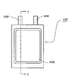
- FIG. 1 shows a sectional view schematically showing a secondary battery which is an example of the electrochemical element of this embodiment.
- the secondary battery 1 shown in FIG. 1 has a positive electrode 10, a negative electrode 20, and a positive electrode 10 and a negative electrode in an exterior body formed of an outer can 40, a sealing can 50, and a resin gasket 60 interposed between them.
- a separator (solid electrolyte layer when the secondary battery is an all-solid secondary battery) 30 and an electrolytic solution (when the secondary battery is a secondary battery having an electrolytic solution) are enclosed between the separator 20 and the battery. ..
- the sealing can 50 is fitted to the opening of the outer can 40 via the gasket 60, and the opening end of the outer can 40 is tightened inward, whereby the gasket 60 comes into contact with the sealing can 50.
- the opening of the outer can 40 is sealed and the inside of the battery has a sealed structure.
- Stainless steel can be used for the outer can and the sealing can.
- polypropylene, nylon, etc. can be used as the material of the gasket, and if heat resistance is required in relation to the use of the battery, tetrafluoroethylene-perfluoroalkoxyethylene copolymer (PFA), etc. can be used.
- PFA tetrafluoroethylene-perfluoroalkoxyethylene copolymer
- FIGS. 2 and 3 show drawings schematically showing another example of the secondary battery which is an example of the electrochemical element of the present embodiment.
- FIG. 2 is a plan view of the secondary battery
- FIG. 3 is a sectional view taken along line II of FIG.
- the secondary battery 100 shown in FIGS. 2 and 3 accommodates an electrode body 200 in a laminated film exterior body 500 composed of two metal laminated films, and the laminated film exterior body 500 has an outer peripheral portion thereof. It is sealed by heat-sealing the upper and lower metal laminating films.
- the electrode body 200 is configured by laminating a positive electrode, a negative electrode, and a solid electrolyte layer interposed between them.
- the electrode body 200 is configured by laminating a positive electrode, a negative electrode, and a separator interposed therein.
- an electrolyte electrolytic solution or the like
- At least one of the positive electrode and the negative electrode of the electrode body 200 is the electrode of the embodiment.
- each layer constituting the laminated film exterior body 500 and each component (positive electrode, negative electrode, etc.) forming the electrode body 200 are distinguished. Not shown.
- the positive electrode of the electrode body 200 is connected to the positive electrode external terminal 300 in the battery 100, and although not shown, the negative electrode of the electrode body 200 is also connected to the negative electrode external terminal 400 in the battery 100. There is.
- the positive electrode external terminal 300 and the negative electrode external terminal 400 are drawn out on one end side to the outside of the laminating film exterior body 500 so that they can be connected to an external device or the like.
- the electrode mixture containing a solid electrolyte is used.
- the electrode mixture according to the electrode of the embodiment may not contain a solid electrolyte.
- the charging / discharging of the battery is performed. It is necessary to introduce Li (Li ion) involved in the above into the active material according to the electrode of the embodiment.
- the active material of the above-described embodiment is pre-doped with Li ions (extra-system pre-doped) by a conventional method, or when the non-aqueous electrolyte secondary battery has a non-aqueous electrolyte solution, the same is used.
- a Li source (metal Li foil, Li alloy foil, etc.) is placed in a place where it can come into contact with the internal non-aqueous electrolyte solution, and Li ions are doped in the active material of the electrode of the embodiment in the battery (inside the system).
- a method such as pre-doping) can be adopted.
- a predoping electrode having a Li source attached to the surface of the current collector and electrically connected to the negative electrode can be used.
- the negative electrode may be, for example, a negative electrode mixture containing only a negative electrode active material and a conductive auxiliary agent, or a negative electrode mixture. Examples thereof include those having a structure in which a layer made of a molded body (negative electrode mixture layer) is formed on a current collector.
- the negative electrode active material for example, graphite, pyrolytic carbons, cokes, glassy carbons, fired organic polymer compounds, mesophase carbon microbeads (MCMB), carbon fibers and other lithium can be stored and released.
- MCMB mesophase carbon microbeads
- One or a mixture of two or more carbon-based materials is used.
- simple substances containing elements such as Al, Si, Sn, Ge, Bi, Sb, In, Zn, and P, compounds and alloys thereof; charged with a low voltage close to that of a lithium metal such as a lithium-containing nitride or a lithium-containing sulfide.
- a compound that can be discharged; a lithium metal can also be used as a negative electrode active material.
- the content of the negative electrode active material in the negative electrode mixture is preferably 15 to 100% by mass.
- the conductive auxiliary agent for the negative electrode the same one as exemplified above as one that can be used for the electrode of the above embodiment can be used.
- the content of the conductive auxiliary agent in the negative electrode mixture is preferably 0.1 to 15% by mass.
- the negative electrode mixture can contain the solid electrolyte.
- the solid electrolyte of the negative electrode includes various sulfide-based solid electrolytes, hydride-based solid electrolytes, halide-based solid electrolytes, and oxide-based solid electrolytes that can be used as the electrode material of the above-described embodiment and exemplified above. One or more of them can be used. In order to improve the battery characteristics, it is desirable to contain a sulfide-based solid electrolyte, and it is more desirable to contain an algyrodite-type sulfide-based solid electrolyte.
- the content of the solid electrolyte in the negative electrode mixture is preferably 4 to 90% by mass.
- the negative electrode mixture may contain a binder, and may not be contained when good moldability can be ensured without using a binder, such as in the case of a negative electrode containing a sulfide-based solid electrolyte. You may.
- a binder such as in the case of a negative electrode containing a sulfide-based solid electrolyte. You may.
- the binder the same ones as exemplified above as those that can be used for the electrodes of the above-described embodiment can be used.
- the content thereof is preferably 15% by mass or less, and more preferably 0.5% by mass or more.
- the content thereof is preferably 0.5% by mass or less, more preferably 0.3% by mass or less. It is more preferably 0% by mass (that is, it does not contain a binder).
- the same current collector as exemplified above can be used as the current collector as the current collector of the above embodiment can be used when the electrode is the negative electrode.
- the molded body of the negative electrode mixture is, for example, compressed by pressure molding or the like by mixing a negative electrode active material with a conductive auxiliary agent, a binder, a solid electrolyte, etc. added as needed. Can be formed with. In the case of a negative electrode composed of only a molded body of a negative electrode mixture, it can be manufactured by the above method.
- a negative electrode having a current collector it can be manufactured by bonding the molded body of the negative electrode mixture formed by the above method by crimping it to the current collector.
- a negative electrode mixture-containing composition in which the negative electrode mixture is dispersed in a solvent is applied to the current collector, dried, and then, if necessary. It can also be manufactured by a method of forming a molded body (negative electrode mixture layer) of a negative electrode mixture on the surface of a current collector by performing pressure molding such as a calender treatment.
- the solvent of the composition containing the negative electrode mixture water, an organic solvent such as NMP, or the like can be used.
- the negative electrode mixture-containing composition also contains a solid electrolyte, it is desirable to select a solvent that does not easily deteriorate the solid electrolyte, and the solvent for the electrode mixture-containing composition containing the solid electrolyte is first selected. It is preferable to use the same solvent as the various solvents exemplified.
- the thickness of the molded body of the negative electrode mixture (in the case of a negative electrode having a current collector, the thickness of the molded body of the positive electrode mixture per one side of the current collector; hereinafter the same) is usually 50 ⁇ m or more. From the viewpoint of increasing the capacity of the battery, it is preferably 200 ⁇ m or more. The thickness of the molded product of the negative electrode mixture is usually 2000 ⁇ m or less.
- the thickness of the negative electrode mixture layer is 50 to 1000 ⁇ m. It is preferable to have.
- the positive electrode may be, for example, a molded body of a positive electrode mixture containing a positive electrode active material, a conductive auxiliary agent, or the like, or a molded body of a positive electrode mixture. Examples thereof include those having a structure in which a layer (positive electrode mixture layer) is formed on a current collector.
- the positive electrode active material is not particularly limited as long as it is a positive electrode active material used in a conventionally known secondary battery, that is, an active material capable of storing and releasing Li ions.
- Specific examples of the positive electrode active material include LiMr Mn 2-r O 4 (where M is Li, Na, K, B, Mg, Ca, Sr, Ba, Ti, V, Cr, Zr, Fe, Co. , Ni, Cu, Zn, Al, Sn, Sb, In, Nb, Ta, Mo, W, Y, Ru and Rh, at least one element selected from the group consisting of 0 ⁇ r ⁇ 1).
- Represented spinnel type lithium manganese composite oxide Li r Mn (1-s-r) Nis M t O (2-u) F v (where M is Co, Mg, Al, B, Ti, V , Cr, Fe, Cu, Zn, Zr, Mo, Sn, Ca, Sr and W, which are at least one element selected from the group consisting of 0.8 ⁇ r ⁇ 1.2, 0 ⁇ s ⁇ 0.
- LiCo 1-r M r O 2 a layered compound represented by LiCo 1-r M r O 2
- M is at least one element selected from the group consisting of Al, Mg, Ti, V, Cr, Zr, Fe, Ni, Cu, Zn, Ga, Ge, Nb, Mo, Sn, Sb and Ba.
- LiNi 1-r Mr O 2 where M is Al, Mg, Ti, Zr, Fe, Co, Cu, Zn, which is a lithium cobalt composite oxide represented by 0 ⁇ r ⁇ 0.5).
- Type composite oxide Li 2 M 1-r N r P 2 O 7 (where M is at least one element selected from the group consisting of Fe, Mn and Co, and N is Al, Mg, Ti. , Zr, Ni, Cu, Zn, Ga, Ge, Nb, Mo, Sn, Sb, V and Ba, which is at least one element selected from the group and is represented by 0 ⁇ r ⁇ 0.5).
- M is at least one element selected from the group consisting of Fe, Mn and Co
- N Al
- Mg Ti.
- Examples thereof include pyrrolate compounds, and only one of these may be used, or two or more thereof may be used in combination.
- the average particle size of the positive electrode active material is preferably 1 ⁇ m or more, more preferably 2 ⁇ m or more, and preferably 10 ⁇ m or less. It is more preferably 8 ⁇ m or less.
- the positive electrode active material may be primary particles or secondary particles in which the primary particles are aggregated. When a positive electrode active material having an average particle size in the above range is used, many interfaces with the solid electrolyte contained in the positive electrode can be obtained, so that the load characteristics of the battery are further improved.
- the positive electrode active material has a reaction suppressing layer on its surface for suppressing the reaction with the solid electrolyte contained in the positive electrode.
- the solid electrolyte may oxidize to form a resistance layer and the ionic conductivity in the molded body may decrease.
- a reaction suppression layer that suppresses the reaction with the solid electrolyte on the surface of the positive electrode active material and preventing direct contact between the positive electrode active material and the solid electrolyte, the ionic conductivity in the molded body due to the oxidation of the solid electrolyte The decrease can be suppressed.
- the reaction suppressing layer may be made of a material having ionic conductivity and capable of suppressing the reaction between the positive electrode active material and the solid electrolyte.
- the material that can form the reaction suppression layer for example, an oxide containing Li and at least one element selected from the group consisting of Nb, P, B, Si, Ge, Ti and Zr, more specifically.
- Examples include Nb-containing oxides such as LiNbO 3 , Li 3 PO 4 , Li 3 BO 3 , Li 4 SiO 4 , Li 4 GeO 4 , LiTIO 3 , LiZrO 3 , Li 2 WO 4 .
- the reaction suppression layer may contain only one of these oxides, or may contain two or more of these oxides, and a plurality of these oxides may be a composite compound. May be formed. Among these oxides, it is preferable to use an Nb - containing oxide, and it is more preferable to use LiNbO3.
- the reaction suppressing layer is preferably present on the surface in an amount of 0.1 to 1.0 part by mass with respect to 100 parts by mass of the positive electrode active material. Within this range, the reaction between the positive electrode active material and the solid electrolyte can be satisfactorily suppressed.
- Examples of the method for forming the reaction suppressing layer on the surface of the positive electrode active material include a sol-gel method, a mechanofusion method, a CVD method, a PVD method, and an ALD method.
- the content of the positive electrode active material in the positive electrode mixture is preferably 20 to 95% by mass.
- the conductive auxiliary agent for the positive electrode the same one as exemplified above as one that can be used for the electrode of the above embodiment can be used.
- the content of the conductive auxiliary agent in the positive electrode mixture is preferably 0.1 to 15% by mass.
- the positive electrode mixture contains a solid electrolyte.
- the positive electrode solid electrolyte includes various sulfide-based solid electrolytes, hydride-based solid electrolytes, halide-based solid electrolytes, and oxide-based solid electrolytes that can be used as the electrode material of the above-described embodiment and are exemplified above. One or more of them can be used. In order to improve the battery characteristics, it is desirable to contain a sulfide-based solid electrolyte, and it is more desirable to contain an algyrodite-type sulfide-based solid electrolyte.
- the content of the solid electrolyte in the positive electrode mixture is preferably 4 to 80% by mass.
- the positive electrode mixture may contain a binder, and may not be contained when good moldability can be ensured without using a binder, such as in the case of a positive electrode containing a sulfide-based solid electrolyte. You may.
- a binder such as in the case of a positive electrode containing a sulfide-based solid electrolyte. You may.
- the binder the same ones as exemplified above as those that can be used for the electrodes of the above-described embodiment can be used.
- the content thereof is preferably 15% by mass or less, and more preferably 0.5% by mass or more.
- the content thereof is preferably 0.5% by mass or less, more preferably 0.3% by mass or less. It is more preferably 0% by mass (that is, it does not contain a binder).
- the same current collector as exemplified above can be used as the current collector as it can be used when the electrode of the above embodiment is a positive electrode.
- the molded body of the positive electrode mixture is, for example, a positive electrode mixture prepared by mixing a positive electrode active material or a conductive auxiliary agent with a binder or a solid electrolyte added as needed, and compressing the positive electrode mixture by pressure molding or the like.
- a positive electrode mixture prepared by mixing a positive electrode active material or a conductive auxiliary agent with a binder or a solid electrolyte added as needed, and compressing the positive electrode mixture by pressure molding or the like.
- a positive electrode having a current collector it can be manufactured by bonding an adult of the positive electrode mixture formed by the above method by crimping it to the current collector.
- a positive electrode mixture-containing composition in which the above-mentioned positive electrode mixture is dispersed in a solvent is applied to the current collector, dried, and then, if necessary. It can also be produced by a method of forming a molded body (positive electrode mixture layer) of a positive electrode mixture on the surface of a current collector by performing pressure molding such as a calender treatment.
- an organic solvent such as NMP can be used as the solvent of the positive electrode mixture-containing composition.
- NMP an organic solvent such as NMP
- the thickness of the molded body of the positive electrode mixture (in the case of a positive electrode having a current collector, the thickness of the molded body of the positive electrode mixture per one side of the current collector; hereinafter the same) is usually 50 ⁇ m or more. From the viewpoint of increasing the capacity of the battery, it is preferably 200 ⁇ m or more. The thickness of the molded product of the positive electrode mixture is usually 2000 ⁇ m or less.
- the thickness of the positive electrode mixture layer is 50 to 1000 ⁇ m. It is preferable to have.
- the solid electrolyte in the solid electrolyte layer interposed between the positive electrode and the negative electrode may be various types that can be used as the electrode material of the above embodiment and exemplified above.
- One or more of sulfide-based solid electrolytes, hydride-based solid electrolytes, halide-based solid electrolytes, and oxide-based solid electrolytes can be used.
- it is desirable to contain a sulfide-based solid electrolyte in order to improve the battery characteristics, it is desirable to contain a sulfide-based solid electrolyte, and it is more desirable to contain an algyrodite-type sulfide-based solid electrolyte.
- the positive electrode, the negative electrode, and the solid electrolyte layer all contain a sulfide-based solid electrolyte, and it is further desirable that the argilodite-type sulfide-based solid electrolyte is contained.
- the solid electrolyte layer may have a porous body such as a non-woven fabric made of resin as a support.
- the solid electrolyte layer is a method of compressing the solid electrolyte by pressure molding or the like; a composition for forming a solid electrolyte layer prepared by dispersing the solid electrolyte in a solvent is applied onto a base material, a positive electrode, and a negative electrode, and dried. If necessary, it can be formed by a method of performing pressure molding such as press processing: or the like.
- the thickness of the solid electrolyte layer is preferably 10 to 500 ⁇ m.
- the separator interposed between the positive electrode and the negative electrode should have sufficient strength and can retain a large amount of non-aqueous electrolyte. Therefore, a microporous film or a non-woven fabric containing polyethylene, polypropylene, or an ethylene-propylene copolymer having a thickness of 10 to 50 ⁇ m and an opening ratio of 30 to 70% is preferable.
- non-aqueous electrolyte solution an organic solvent in which an electrolyte salt such as a lithium salt is dissolved is used.
- the organic solvent is not particularly limited, and is, for example, a chain ester such as dimethyl carbonate, diethyl carbonate, ethylmethyl carbonate, or methylpropyl carbonate; a dielectric such as ethylene carbonate, propylene carbonate, butylene carbonate, or vinylene carbonate. Examples thereof include a cyclic ester having a high rate; a mixed solvent of a chain ester and a cyclic ester; and a mixed solvent of a cyclic ester having a chain ester as a main solvent is particularly suitable.
- Examples of the electrolyte salt to be dissolved in the organic solvent in the preparation of the non-aqueous electrolyte solution include LiPF 6 , LiBF 4 , LiAsF 6 , LiSbF 6 , LiCF 3 SO 3 , LiC 4 F 9 SO 3 , LiCF 3 CO 2 , and Li 2 .
- Rf and Rf'are fluoroalkyl groups are used alone or in admixture of two or more.
- the concentration of the electrolyte salt in the non-aqueous electrolyte solution is not particularly limited, but is preferably 0.3 mol / l or more, more preferably 0.4 mol / l or more, and 1.7 mol / l or more. It is preferably less than or equal to, and more preferably 1.5 mol / l or less.
- a gel-like electrolyte obtained by gelling the non-aqueous electrolyte solution with a gelling agent made of a polymer or the like can also be used.
- an aqueous electrolyte When the negative electrode of the secondary battery is the electrode of the above embodiment, an aqueous electrolyte can also be used.
- the aqueous electrolyte include a composition in which more than 4 mol to 15 mol of water is mixed with 1 mol of an alkali metal salt containing an organic anion having a fluoroalkyl group as a component.
- the positive electrode and the negative electrode can be used in a battery in the form of a laminated electrode body laminated via a solid electrolyte layer or a separator, or a wound electrode body obtained by winding the laminated electrode body.
- an electrode body having a solid electrolyte layer it is preferable to perform pressure molding in a state where the positive electrode, the negative electrode and the solid electrolyte layer are laminated from the viewpoint of increasing the mechanical strength of the electrode body.
- the form of the secondary battery is as shown in FIG. 1, which has an outer body composed of an outer can, a sealing can, and a gasket, that is, a form generally called a coin-shaped battery or a button-shaped battery.
- FIGS. 2 and 3 in addition to those having an exterior body made of a resin film or a metal-resin laminated film, a metal bottomed tubular (cylindrical or square tubular) outer can. And may have an exterior body having a sealing structure for sealing the opening.
- Example 1 ⁇ Synthesis of active substances> Active materials were synthesized using a solid phase reaction method using powders of various metal oxides (all obtained from High Purity Chemistry Co., Ltd.) as starting materials. Nb 2 O 5 (purity:> 99.9%), ⁇ -Al 2 O 3 (purity:> 99.99%) and ZnO (purity:> 99.99%), 14.507 g, 427.6 mg, respectively. , 80.3 mg was weighed and mixed. The mixture of starting materials is added to a zirconia container having an internal volume of 500 ml together with ethanol: 15 g and YSZ balls having a diameter of 5 mm: 120 g, and a planetary ball mill [Fritsch's "planaterym”.
- the precursor powder of the active substance is obtained by drying the slurry obtained by separating the zirconia balls from the sample after the mixing treatment for 3 hours under the condition of 250 rpm with "ill pulveristte 5" (trade name)]. Obtained.
- the precursor powder was transferred to an alumina crucible, heated to 1150 ° C. at a heating rate of 16 ° C./min under an air atmosphere, kept as it was for 8 hours, and naturally cooled to room temperature.
- the obtained powder was crushed in a mortar for 5 minutes and passed through a sieve having an opening of 150 ⁇ m to obtain a crude product of an active substance.
- a lithium metal plate having a diameter of 10 mm and a thickness of 100 ⁇ m and an indium metal plate having a diameter of 10 mm and a thickness of 100 ⁇ m bonded by a rolling method is placed as a negative electrode on the solid electrolyte layer side of the laminate, and then the diameter is 10 mm and the thickness is 10 mm.
- a 1 mm SUS disk was placed on the positive electrode side and the negative electrode side and fixed to form a laminated electrode body. Using the laminated electrode body, a sheet-shaped all-solid-state battery similar to that shown in FIG. 2 was produced.
- Laminating film A positive electrode current collector foil (SUS foil) and a negative electrode current collector foil (SUS foil) are placed laterally on the inner surface of the aluminum laminate film constituting the exterior body with a certain distance between them. I pasted them side by side.
- Each of the current collector foils has a main body portion facing the positive electrode side surface or the negative electrode side surface of the laminated electrode body, and a positive electrode external terminal 300 and a negative electrode external terminal 400 protruding from the main body portion toward the outside of the battery. The one cut into a shape having a portion was used.
- the laminated electrode body is placed on the negative electrode collecting foil of the laminated film outer body, and the laminated electrode body is wrapped with the laminated film outer body so that the positive electrode current collecting foil is arranged on the positive electrode of the laminated electrode body.
- the remaining three sides of the laminated film exterior body were sealed by heat fusion under vacuum to obtain a sheet-shaped all-solid-state secondary battery.
- Example 2 A sheet-shaped all-solid-state secondary battery was produced in the same manner as in Example 1 except that the active material was changed to the monoclinic Zn 0.2 Al 0.7 Nb 11.1 O 29 . It was confirmed in the same manner as in Example 1 that the active material used for the positive electrode was a monoclinic crystal type crystal.
- Example 3 A sheet-shaped all-solid-state secondary battery was produced in the same manner as in Example 1 except that the active material was changed to the monoclinic Zn 0.3 Al 0.55 Nb 11.15 O 29 . It was confirmed in the same manner as in Example 1 that the active material used for the positive electrode was a monoclinic crystal type crystal.
- Example 4 A sheet-shaped all-solid-state secondary battery was produced in the same manner as in Example 1 except that the active material was changed to the monoclinic type Cu 0.1 Al 0.85 Nb 11.05 O 29 . It was confirmed in the same manner as in Example 1 that the active material used for the positive electrode was a monoclinic crystal type crystal.
- Example 5 A sheet-shaped all-solid-state secondary battery was produced in the same manner as in Example 1 except that the active material was changed to the monoclinic type Cu 0.2 Al 0.7 Nb 11.1 O 29 . It was confirmed in the same manner as in Example 1 that the active material used for the positive electrode was a monoclinic crystal type crystal.
- Example 6 A sheet-shaped all-solid-state secondary battery was produced in the same manner as in Example 1 except that the active material was changed to the monoclinic type Cu 0.3 Al 0.55 Nb 11.15 O 29 . It was confirmed in the same manner as in Example 1 that the active material used for the positive electrode was a monoclinic crystal type crystal.
- Comparative Example 1 A sheet-shaped all-solid-state secondary battery was produced in the same manner as in Example 1 except that the active material was changed to the monoclinic type AlNb 11 O 29 . It was confirmed in the same manner as in Example 1 that the active material used for the positive electrode was a monoclinic crystal type crystal.
- Comparative Example 2 A sheet-shaped all-solid-state secondary battery was produced in the same manner as in Example 1 except that the active material was changed to the monoclinic type Zn 0.67 Nb 11.33 O 29 (Zn 2 Nb 34 O 87 ). It was confirmed in the same manner as in Example 1 that the active material used for the positive electrode was a monoclinic crystal type crystal.
- Comparative Example 3 A sheet-shaped all-solid-state secondary battery was produced in the same manner as in Example 1 except that the active material was changed to the monoclinic Zn 0.566 Al 0.1 Nb 11.31 O 29 . It was confirmed in the same manner as in Example 1 that the active material used for the positive electrode was a monoclinic crystal type crystal.
- Comparative Example 4 A sheet-shaped all-solid-state secondary battery was produced in the same manner as in Example 1 except that the active material was changed to the monoclinic Ti 2 Nb 10 O 29 . It was confirmed in the same manner as in Example 1 that the active material used for the positive electrode was a monoclinic crystal type crystal.
- Comparative Example 5 A sheet-shaped all-solid-state secondary battery was produced in the same manner as in Example 1 except that the active material was changed to the monoclinic TiNb 2 O 7 . It was confirmed in the same manner as in Example 1 that the active material used for the positive electrode was a monoclinic crystal type crystal.
- the charging capacity (0.24C charging capacity) was measured by constantly charging with a current value of 24C until the voltage became 1.88V. Then, for each battery, the 0.24C charge capacity was divided by the initial capacity to obtain the capacity retention rate, and the load characteristics were evaluated by this.
- the sheet-shaped all-solid-state secondary batteries of Examples 1 to 6 having a positive electrode using an oxide represented by the general formula (1) as an active material have a capacity retention rate and a capacity retention rate at the time of load characteristic evaluation. Both of the capacity retention rates at the time of charge / discharge cycle characteristic evaluation were high, and they had excellent load characteristics and charge / discharge cycle characteristics.
- the battery of Comparative Example 1 using a positive electrode using an oxide containing no element M1 as an active material and Comparative Examples 2, 4 and 5 using a positive electrode using an oxide containing no Al as an active material.
- the battery of Comparative Example 3 using a battery and a positive electrode using an oxide having an inappropriate amount of element M1 as an active material has either a capacity retention rate at the time of load characteristic evaluation or a capacity retention rate at the time of charge / discharge cycle characteristic evaluation. It was lower than the battery of the example, and the load characteristic and the charge / discharge cycle characteristic were inferior.
- Example 7 ⁇ Preparation of positive electrode material> 0.86 g of lithium and 38.7 g of pentaethoxyniobium were mixed in 394 g of dehydrated ethanol to prepare a coating solution for forming a reaction-suppressing layer. Next, in a coating apparatus using a rolling fluidized bed, the reaction-suppressing layer forming coating solution was applied on 1000 g of the positive electrode active material (LiNi 0.5 Mn 1.5 O 4 ) at a rate of 2 g per minute. Applied. By heat-treating the obtained powder at 350 ° C., a positive electrode material having a reaction suppressing layer composed of 2 parts by mass of LiNbO 3 formed on the surface thereof was obtained with respect to 100 parts by mass of the positive electrode active material.
- the positive electrode active material LiNi 0.5 Mn 1.5 O 4
- a positive electrode mixture was prepared by mixing the positive electrode material, gas phase growth carbon fiber (conductive auxiliary agent), and Li 5.8 PS 4.6 Cl 1.6 (sulfide-based solid electrolyte). The mixing ratio of the positive electrode material, the conductive auxiliary agent, and the sulfide-based solid electrolyte was 67: 4: 29 in mass ratio.
- This positive electrode mixture 102 mg is put into a powder molding die having a diameter of 7.5 mm, and molding is performed at a pressure of 1000 kgf / cm 2 using a press machine to prepare a positive electrode made of a cylindrical positive electrode mixture molded body. bottom.
- a flexible graphite sheet "PERMA-FOIL (product name)" (thickness: 0.1 mm, apparent density: 1.1 g / cm 3 ) manufactured by Toyo Tanso Co., Ltd. punched out to the same size as the laminated electrode body.
- Two sheets were prepared, and one of them was placed on the inner bottom surface of a stainless steel sealing can fitted with an annular gasket made of polypropylene.
- the laminated electrode body is superposed on the graphite sheet with the negative electrode on the graphite sheet side, another sheet of the graphite sheet is placed on the laminated electrode body, and the outer can made of stainless steel is further covered.
- Example 8 A flat all-solid-state secondary battery was produced in the same manner as in Example 7 except that the negative electrode active material was changed to the monoclinic type Cu 0.1 Al 0.85 Nb 11.05 O 29 .
- Comparative Example 6 A flat all-solid-state secondary battery was produced in the same manner as in Example 7 except that the negative electrode active material was changed to the monoclinic type AlNb 11 O 29 .
- the all-solid-state batteries of Example 7, Example 8 and Comparative Example 6 are constantly charged with a current value of 0.07 C until the voltage reaches 3.8 V, and then a constant voltage until the current value reaches 0.005 C. After charging, constant current discharge was performed at a current value of 0.07 C until the voltage reached 1.5 V, and the initial capacity was determined. Constant current charging and constant voltage charging were performed again, and then constant current step discharge was performed, and the discharge capacity (constant current step discharge capacity) at each current value was measured. In the constant current step discharge, the charged battery is discharged with a constant current until the voltage reaches 1.5 V at a current value of 0.6 C, and then until the voltage reaches 1.5 V at a current value of 0.3 C.
- the charged battery is discharged with a constant current until the voltage reaches 1.5 V at a current value of 0.6 C, and then until the voltage reaches 1.5 V at a current value of 0.3 C. This was performed by constant current discharge and then constant current discharge at a current value of 0.1 C until the voltage reached 1.5 V. Then, the sum (0.1C discharge capacity) of all the constant current step discharge capacities of 0.6C to 0.1C was obtained. Subsequently, each battery is charged with a constant current at a current value of 0.3C until it reaches 3.8V, and then charged with a constant voltage until it reaches 0.005C, and then 0.6C to 0 under the same conditions as described above. A constant current step discharge of .1C was performed, and a 0.1C discharge capacity was measured.
- the operation at the time of initial capacity measurement is set as the first cycle, the final constant voltage charge is performed at a current value of 0.3 C, and then the constant current step discharge operation is performed.
- the cycle is set, the 0.1C discharge capacity of the third cycle is divided by the 0.1C discharge capacity of the charge / discharge cycle (second cycle) in which constant current charging is performed at a current value of 0.1C.
- the charge / discharge cycle characteristics were evaluated.
- Table 2 shows the evaluation results of the all-solid-state batteries of Example 7, Example 8 and Comparative Example 6 as relative values when the result of the all-solid-state battery of Comparative Example 6 is 100.
- the flat all-solid-state secondary batteries of Examples 7 and 8 having a negative electrode using an oxide represented by the general formula (1) as an active material have a capacity retention rate and a capacity retention rate at the time of load characteristic evaluation. Both of the capacity retention rates at the time of charge / discharge cycle characteristic evaluation were high, and they had excellent load characteristics and charge / discharge cycle characteristics.
- the battery of Comparative Example 6 using the negative electrode using the oxide containing no element M 1 as the active material has both the capacity retention rate at the time of load characteristic evaluation and the capacity retention rate at the time of charge / discharge cycle characteristic evaluation.
- the load characteristic and the charge / discharge cycle characteristic were inferior.
- Example 9 A sheet-shaped all-solid-state secondary battery was produced in the same manner as in Example 1 except that the active material was changed to the monoclinic type Cu 0.21 Al 0.74 Nb 11.05 O 27.89 . It was confirmed in the same manner as in Example 1 that the active material was a monoclinic crystal type. The composition of the active material was determined by ICP-AES measurement and measurement by an oxygen-nitrogen analyzer.
- Example 10 A mixture of powders of various metal oxides (all obtained from High Purity Chemical Co., Ltd.) is placed in a carbon container and fired at 1000 ° C. for 4 hours in a vacuum atmosphere with a pressure of 100 Pa or less for reduction treatment. , A monoclinic type Cu 0.14 Al 0.73 Nb 11.13 O 28.00 was obtained. A sheet-shaped all-solid-state secondary battery was produced in the same manner as in Example 1 except that the active material was changed to the monoclinic type Cu 0.14 Al 0.73 Nb 11.13 O 28.00 . .. It was confirmed in the same manner as in Example 1 that the active material was a monoclinic crystal type. The composition of the active material was determined by ICP-AES measurement and measurement by an oxygen-nitrogen analyzer.
- Example 11 A sheet-shaped all-solid-state secondary battery was produced in the same manner as in Example 1 except that the active material was changed to the monoclinic Fe 0.20 Al 0.83 Nb 10.97 O 28.23 . It was confirmed in the same manner as in Example 1 that the active material was a monoclinic crystal type. The composition of the active material was determined by ICP-AES measurement and measurement by an oxygen-nitrogen analyzer.
- Comparative Example 7 A sheet-shaped all-solid-state secondary battery was produced in the same manner as in Example 1 except that the active material was changed to a monoclinic type Al 0.87 Nb 11.13 O 28.47 which had been subjected to a reduction treatment. It was confirmed in the same manner as in Example 1 that the active material was a monoclinic crystal type. The composition of the active material was determined by ICP-AES measurement and measurement by an oxygen-nitrogen analyzer.
- the load characteristics and charge / discharge cycle characteristics of the sheet-shaped all-solid-state secondary batteries of Examples 9 to 11 and Comparative Example 7 were evaluated in the same manner as the batteries of Example 1 except that the lower limit discharge voltage was changed to 0.18 V. At the same time, the battery capacity was divided by the weight of the active material contained in the electrode to obtain the energy density per active material weight.
- the sheet-shaped all-solid-state secondary batteries of Examples 9 to 11 having a positive electrode using an oxide represented by the general formula (1) as an active material have a capacity at the time of load characteristic evaluation. Both the retention rate and the capacity retention rate at the time of charge / discharge cycle characteristic evaluation were high, and compared to having excellent load characteristics and charge / discharge cycle characteristics, the aluminum niobium composite oxide containing no element M1 was used. In the battery of Comparative Example 7 having a positive electrode as an active material, both the capacity retention rate at the time of load characteristic evaluation and the capacity retention rate at the time of charge / discharge cycle characteristic evaluation were inferior.
- the reduction treatment is performed in a carbon container, the Z value is suitable, the absorbances A1, A2 and A3 satisfy the relationship of A1 ⁇ A2 and A3 ⁇ A2, and the atomic ratio P and the atomic ratio Q are P.
- the battery of Example 10 having a positive electrode using the oxide as an active material satisfying the relationship of> Q includes the batteries of Examples 9 and 11 having a positive electrode using the oxide as an active material which has not been subjected to the reduction treatment.
- the energy density was higher than that of the battery of Comparative Example 7 having a positive electrode using an aluminum niobium composite oxide containing no element M 1 as an active material.
- the present invention can be implemented in a form other than the above as long as it does not deviate from the gist thereof.
- the embodiments disclosed in the present application are examples, and the present invention is not limited to these embodiments.
- the scope of the present invention shall be construed in preference to the description of the attached claims over the description of the above specification, and all changes within the scope of the claims shall be within the scope of the claims. included.
- the electrochemical element of the present invention includes a secondary battery having a conventionally known non-aqueous electrolyte (non-aqueous electrolyte solution or gel-like electrolyte), a secondary battery having an aqueous electrolyte, an all-solid secondary battery, and a super capacitor. It can be applied to the same applications as. Further, the electrode for an electrochemical element of the present invention can constitute the electrochemical element of the present invention, and the active material for an electrochemical element of the present invention and the electrode material for an electrochemical element of the present invention are the electrodes for an electrochemical element of the present invention. Can be configured.
- the electrochemical element of the present invention has excellent load characteristics, applications in which such characteristics are often required, for example, industrial equipment and mobile vehicles (electric vehicles and hybrid cars, etc.) It is suitable for power supply applications for vehicles such as electric motorcycles, ships, submarines, radio-controlled models, flying objects such as rockets and artificial satellites, and drones.
- vehicles such as electric motorcycles, ships, submarines, radio-controlled models, flying objects such as rockets and artificial satellites, and drones.
- some moving objects, such as hybrid cars charge the battery used by regenerative energy, but in this case, the charging current and voltage may not be stable, so in the battery Dendrite of element A is likely to occur, which may cause deterioration of the battery.
- the electrochemical element of the present invention uses an oxide that is unlikely to generate dendrite of element A as an active material, it is possible to suppress deterioration caused by dendrite of element A even if it is charged by regenerative energy. Therefore, it can be preferably applied to a moving body or the like that may perform such charging.
Landscapes
- Chemical & Material Sciences (AREA)
- Organic Chemistry (AREA)
- Inorganic Chemistry (AREA)
- Engineering & Computer Science (AREA)
- Electrochemistry (AREA)
- Chemical Kinetics & Catalysis (AREA)
- General Chemical & Material Sciences (AREA)
- Materials Engineering (AREA)
- Power Engineering (AREA)
- Manufacturing & Machinery (AREA)
- Microelectronics & Electronic Packaging (AREA)
- General Physics & Mathematics (AREA)
- Physics & Mathematics (AREA)
- Condensed Matter Physics & Semiconductors (AREA)
- Battery Electrode And Active Subsutance (AREA)
- Secondary Cells (AREA)
- Inorganic Compounds Of Heavy Metals (AREA)
Abstract
負荷特性と充放電サイクル特性と優れる電気化学素子、前記電気化学素子を構成し得る電極活物質、その製造方法、電極材料および電極、並びに前記電気化学素子を有する移動体を提供する。 本発明の電気化学素子用電極活物質は、単斜晶型の結晶構造を有しており、下記一般式(1)を満たす酸化物を含むことを特徴とするものである。 AyM1
αAlx-αNb12-x-zM2
zO29-δ (1) 〔前記一般式(1)中、AはLiおよびNaのうちの少なくとも一方の元素、M1はFe、Mn、Zn、Cu、Ag、Mg、Ca、Sr、Ba、Co、Eu、Y、Bi、La、Ce、Nd、SmおよびGdよりなる群から選択される少なくとも1種の元素、M2は特定の元素であり、0<x≦1.1、0≦y≦24、0≦z≦2、-1≦δ≦2、0<α≦0.4xである。〕
Description
本発明は、負荷特性と充放電サイクル特性とに優れる電気化学素子、前記電気化学素子を構成し得る電極活物質、その製造方法、電極材料および電極、並びに前記電気化学素子を有する移動体に関するものである。
電気化学素子の一種である非水電解質二次電池は、携帯電話、ノート型パーソナルコンピュータなどのポータブル電子機器や、電気自動車などの電源用途に利用されているが、これらの小型化や高機能化などに伴って、非水電解質二次電池にも、より小型・軽量で、かつ高容量・高エネルギー密度であることが求められている。
現在の非水電解質二次電池では、通常、正極活物質にリチウム含有複合酸化物が用いられ、負極活物質に黒鉛などが用いられている。
また、例えば負極でのリチウム析出による内部短絡を起こさずに大きな電流値で充放電可能な電池を構成するために、負極活物質にスピネル型のチタン酸リチウム(Li4Ti5O12)を使用することも試みられている。ところが、チタン酸リチウムは、理論容量〔175mAh/g(600mAh/cm3)〕が黒鉛の理論容量〔372mAh/g(830mAh/cm3)〕に比べて小さく、かかる点において課題を抱えている。
こうしたことから、近年、チタン酸リチウムよりも容量が大きい負極活物質として、TiNb2O7、Ti2Nb10O29、AlNb11O29、Zn2Nb34O87、Cu0.02Ti0.94Nb2.04O7などのニオブと他の金属との酸化物の適用が検討されている(特許文献1~5、非特許文献1~4など)。
Electrochemistry Communications、2012年、25巻、39-42頁
ACS Applied Material Interfaces、2019年、11巻、6086-6096頁
Journal of Materials Chemistry A、2019年、7巻、25537-25547頁
Journal of Power Sources、2016年、328巻、336-344頁
ところで、非水電解質二次電池には、負荷特性や充放電サイクル特性の向上も求められているが、特許文献1~5や非特許文献1~4に開示されているような材料を活物質とした場合、負荷特性と充放電サイクル特性との両立が困難である。
本発明は、前記事情に鑑みてなされたものであり、その目的は、負荷特性と充放電サイクル特性と優れる電気化学素子、前記電気化学素子を構成し得る電極活物質、その製造方法、電極材料および電極、並びに前記電気化学素子を有する移動体を提供することにある。
本発明の電気化学素子用電極活物質は、単斜晶型の結晶構造を有しており、下記一般式(1)を満たす酸化物であることを特徴とするものである。
AyM1
αAlx-αNb12-x-zM2
zO29-δ (1)
前記一般式(1)中、AはLiおよびNaのうちの少なくとも一方の元素、M1はFe、Mn、Zn、Cu、Ag、Mg、Ca、Sr、Ba、Co、Eu、Y、Bi、La、Ce、Nd、SmおよびGdよりなる群から選択される少なくとも1種の元素、M2はK、Ti、Ni、Zr、V、Mo、TaおよびWよりなる群から選択される少なくとも1種の元素であり、0<x≦1.1、0≦y≦24、0≦z≦2、-1≦δ≦2、0<α≦0.4xである。
また、本発明の電気化学素子用電極材料は、本発明の電気化学素子用電極活物質を含有することを特徴とするものである。
さらに、本発明の電気化学素子用電極は、本発明の電気化学素子用電極活物質を含有するか、または本発明の電気化学素子用電極材料を含有することを特徴とするものである。
そして、本発明の電気化学素子は、正極および負極を有し、前記正極および前記負極のいずれか一方が本発明の電気化学素子用電極であることを特徴とするものである。
また、本発明の移動体は、本発明の電気化学素子を有することを特徴とするものである。
なお、本発明の電気化学素子用電極活物質は、前記一般式(1)で表される酸化物またはその前駆体を、真空雰囲気下において、カーボン製の容器内で焼成する工程を経て製造することで、その特性をより高めることができる。
本発明によれば、負荷特性と充放電サイクル特性と優れる電気化学素子、前記電気化学素子を構成し得る電極活物質、その製造方法、電極材料および電極、並びに前記電気化学素子を有する移動体を提供することができる。
以下、本発明を実施形態に基づいて説明する。
<電気化学素子用電極活物質>
本実施形態の電気化学素子用電極活物質(以下、単に「活物質」という場合がある)は、単斜晶型の結晶構造を有しており、下記一般式(1)を満たす酸化物である。
本実施形態の電気化学素子用電極活物質(以下、単に「活物質」という場合がある)は、単斜晶型の結晶構造を有しており、下記一般式(1)を満たす酸化物である。
AyM1
αAlx-αNb12-x-zM2
zO29-δ (1)
前記一般式(1)中、AはLiおよびNaのうちの少なくとも一方の元素、M1はFe、Mn、Zn、Cu、Ag、Mg、Ca、Sr、Ba、Co、Eu、Y、Bi、La、Ce、Nd、SmおよびGdよりなる群から選択される少なくとも1種の元素、M2はK、Ti、Ni、Zr、V、Mo、TaおよびWよりなる群から選択される少なくとも1種の元素であり、0<x≦1.1、0≦y≦24、0≦z≦2、-1≦δ≦2、0<α≦0.4xである。
元素M1であるFe(Fe2+)、Mn(Mn2+)、Zn(Zn2+)、Cu(Cu+、Cu2+)、Ag(Ag+)、Mg(Mg2+)、Ca(Ca2+)、Sr(Sr2+)、Ba(Ba2+)、Co(Co2+)、Eu(Eu2+、Eu3+)、Y(Y3+)、Bi(Bi3+)、La(La3+)、Ce(Ce3+、Ce4+)、Nd(Nd3+)、Sm(Sm3+)およびGd(Gd3+)は、Nb(Nb5+)やAl(Al3+)よりも有効イオン半径が大きい。よって、前記一般式(1)で表される酸化物は、AlNb11O29をベースとし、そのAlの一部が元素M1によって置換されていることで、AlNb11O29に比べて結晶の格子定数が大きくなり、内部での元素Aイオンの拡散性が増大する。そのため、本実施形態の活物質を用いて構成した電気化学素子においては、その負荷特性が向上する。
なお、AlNb11O29において、Alは、その結晶構造を安定にする作用を有しており、その一部を元素M1で置換することで、酸化物の結晶構造の安定性が損なわれることも考えられ、これにより、この酸化物を活物質として構成した電気化学素子において、充放電を繰り返した際に、容量低下がより生じやすくなる(充放電サイクル特性が低下する)ことが予想される。
しかしながら、こうした予想に反して、前記一般式(1)で表されるように、元素M1によってAlを置換する量が一定範囲内であれば、この酸化物を活物質として構成した電気化学素子において、充放電を繰り返した際の容量低下を、AlNb11O29を使用した場合よりも良好に抑えることができる。その理由は、イオン半径がNb(Nb5+)やAl(Al3+)より大きい元素M1を含有させることで、キャリアとなる元素Aイオンが挿入される前の段階における前記酸化物の格子定数が大きくなり、元素Aイオンが吸蔵される空間が広がることで、充放電に伴う元素Aイオンの挿入・脱入の際の酸化物(活物質)の体積変化を抑制することができることから、電気化学素子の充放電を繰り返しても、電極の劣化を抑えることが可能となるためであると推測される。
このように、本実施形態の活物質によれば、電気化学素子の負荷特性向上と高い充放電サイクル特性の維持とを両立することが可能となる。
前記一般式(1)で表される酸化物は、元素M1として、Fe、Mn、Zn、Cu、Ag、Mg、Ca、Sr、Ba、Co、Eu、Y、Bi、La、Ce、Nd、SmおよびGdのうちのいずれか1種の元素のみを含有していてもよく、2種以上を含有していてもよい。これらの元素M1の中でも、電子配置の関係から特にAlを置換しやすく、また、前記酸化物の電子伝導性を高める効果が高いことから、Fe、Mn、Zn、Cuが好ましく、Zn、Cuがより好ましい。
なお、前記一般式(1)で表される酸化物が、元素M1として、例えばFe3+/Fe2+やCu2+/Cu+など、複数の価数が混在する元素を含有する場合には、酸素欠損が多く生じる〔すなわち、前記一般式(1)において、δが0より大きくなる〕ことがあり、これにより、前記一般式(1)で表される酸化物の電子伝導性およびイオン伝導性がより向上する。よって、前記一般式(1)で表される酸化物が、元素MとしてFeやCuを含有する場合には、電気化学素子の負荷特性のさらなる向上が期待できる。
また、前記一般式(1)で表される酸化物は、Alの一部を置換する元素M1と別に、K、Ti、Ni、Zr、V、Mo、TaおよびWよりなる群から選択される少なくとも1種の元素M2を含有していてもよい。これらの元素M2は、単斜晶型の結晶構造を有する前記一般式(1)で表される酸化物において、結晶を構成するAlの一部を置換せずに、Nbを置換しているか、あるいは結晶中に固溶したり不純物として含まれたりする成分である。前記一般式(1)で表される酸化物は、元素M2を含有していなくてもよく、その量zは0であってもよいが、元素M2を含む場合は、その量zが2以下であれば、本実施形態の活物質の性能に影響しないため許容される。また、前記一般式(1)で表される酸化物は、水分を含んでいてもよい。
前記一般式(1)で表される酸化物において、Alは、前記酸化物の構造安定性を高めるための成分であり、このAlの作用によって、電気化学素子の充放電時における活物質の可逆性が向上する。
前記一般式(1)で表される酸化物において、前記の通り、Alの一部は元素M1によって置換されているが、Alの量と元素M1の量との合計xは、0より大きく、Alおよび元素M1による前記の各作用をより良好に発揮させる観点から、0.8以上であることが好ましい。ただし、前記酸化物中のAlおよび元素M1の量が多すぎると、前記酸化物におけるNbの量が少なくなりすぎて、その作用が良好に発揮されない虞があることから、Alの量と元素M1の量との合計xは、1.1以下であり、1.05以下であることが好ましい。
また、前記一般式(1)で表される酸化物において、元素M1の量αは、0より大きく、また、電気化学素子に負荷特性を高める効果をより良好に確保する観点から、0.05以上であることが好ましい。ただし、前記一般式(1)で表される酸化物において、元素M1の量が多すぎると、結晶構造の安定性が低下して、電気化学素子の充放電サイクル特性を高く維持できない虞がある。よって、電気化学素子の充放電サイクル特性を良好にする観点からは、前記一般式(1)で表される酸化物において、元素M1の量αは、0.4x以下であり、より具体的には、0.44以下であることが好ましく、0.4以下であることがより好ましい。
前記一般式(1)で表される酸化物において、元素Aは、LiおよびNaのうちの少なくとも一方の元素であり、電気化学素子の充放電により、前記酸化物に吸蔵されたり、前記酸化物から脱離したりする(すなわち、キャリアとして機能する)。前記酸化物は、元素Aを含有していなくてもよく、含有していてもよい。元素Aを含有しない前記酸化物の場合は、例えば負極活物質として使用された電気化学素子の充電や、電気化学素子に使用する前の元素Aのイオンのプレドープにより、元素Aのイオンが挿入されて元素Aを含有するようになる。
前記一般式(1)で表される酸化物における元素Aの量yは、0以上24以下である。
前記一般式(1)で表される酸化物において、酸素の量は、本来はAlNb11O29と同様に29であるが、元素M1が存在することなどによって変動する場合がある。具体的には、前記一般式(1)において、δは、-1以上であり、2以下、好ましくは1.95以下である。前記一般式(1)におけるδが0より大きいときには、前記酸化物において酸素欠損が生じていることになるが、この場合、前記酸化物を含む活物質の電子伝導性および元素Aイオンの伝導性が向上するため、このような活物質を使用することで、電気化学素子のエネルギー密度をより高めることが可能となる。
前記一般式(1)で表される酸化物において、酸素の量に関するδは、陽イオンを形成する元素M1、元素M2、NbおよびAlの量と、陰イオンを形成する酸素の量とによって決定される。
本実施形態の活物質のうち、より好ましい形態の一つとして、前記一般式(1)で表される酸化物として、下記一般式(2)を満たすものを含むものが挙げられる。
M1
αAl1-1.5αNb11+0.5αO29-δ (2)
前記一般式(2)における元素M1は、ZnおよびCuのうちの少なくとも一方であり、0<α≦0.4、0≦δ≦0.5αである。そして、前記一般式(2)における元素M1の量αは、0.05以上であることが好ましく、0.4以下であることが好ましく、0.35以下であることがより好ましい。また、前記一般式(2)において、酸素の量に関するδは、0以上0.5α以下であるが、前記の通り、0<α≦0.4であるため、δの値は0以上0.2以下となる。
前記一般式(1)で表され、かつ前記一般式(2)を満たす酸化物は、Liイオンが挿入されることで、例えば下記一般式(3)を満たすようになる。
LiyM1
αAl1-1.5αNb11+0.5αO29-δ (3)
前記一般式(3)において、元素M1、その量αおよび酸素の量に関するδは、前記一般式(2)と同じであり、0<y≦22である。
本実施形態の活物質においては、前記一般式(1)で表される酸化物が還元処理を施されたものであることが好ましい。前記酸化物においては、通常、Nbは通常5価(Nb5+)であるが、還元処理されることで4価のNb(Nb4+)が混在するようになる。Nb4+はNb5+よりもイオン半径が大きいため、前記酸化物中において4価のNbが存在することで、単斜晶型の結晶構造を有する前記酸化物の格子サイズが大きくなる。また、前記一般式(1)で表される酸化物が元素M1を含有するだけでなく、還元処理されることによっても酸素欠損が生じる〔その結果、前記一般式(1)におけるδの値が大きくなる〕。還元処理された前記酸化物を含む活物質では、前記の格子サイズの増大による作用と、酸素欠損による作用とが相乗的に機能して、電子伝導性および元素Aイオンの拡散性がより向上する。よって、還元処理を施された前記酸化物を含む活物質を使用することで、例えば電気化学素子のエネルギー密度をより高めることが可能となる。
活物質が以下の(a)または(b)を満たしている場合には、活物質の電子伝導性および元素Aイオンの拡散性がより向上する程度に、活物質中の前記酸化物が還元処理されているといえる。
(a)活物質に含まれる前記一般式(1)で表される酸化物における全Nb中のNb4+の比率Z(原子%)が、3.5≦Z≦30。
(b)前記酸化物を含む活物質において、波長500nmにおける吸光度をA1、波長600nmにおける吸光度をA2、および波長700nmにおける吸光度をA3としたとき、A1<A2の関係を満たし、かつA3<A2の関係を満たす。
前記酸化物を含む活物質は、還元処理を施すことで白色乃至黄色から、青色に変色する。よって、前記(b)を満たす場合、すなわち、A1<A2の関係を満たし、かつA3<A2の関係を満たす場合には、活物質中の前記酸化物が、活物質の電子伝導性および元素Aイオンの拡散性が向上する程度に、前記酸化物が還元処理されていると判断できる。
還元処理が施される前記酸化物のより具体的な一態様として、例えば、前記一般式(1)で表されるものうち、元素M1がFe、CuおよびZnよりなる群から選択される少なくとも1種の元素で、0<δ≦2であるものが挙げられる。
なお、還元処理を経た前記酸化物を含む活物質においては、その表面と内部とで、元素M1の割合が異なり、元素M1が表面部分に偏在する傾向がある。具体的には、活物質において、X線光電子分光分析(XPS)によって求められるNbに対する元素M1の原子比率P(Nb原子の数を100としたときの、元素M1原子の数の比率。原子比率Qについても同じ。)と、誘導結合プラズマ発光分光分析(Inductively Coupled Plasma Atomic Emission Spectroscopy:ICP-AES)によって求められるNbに対する元素M1の原子比率Qとが、P>Qの関係を満たすことが好ましい。この場合には、電気化学素子のエネルギー密度を向上させる効果がより良好となる。
本実施形態の活物質において、活物質全量中の、単斜晶型の結晶構造を有し、かつ前記一般式(1)で表される酸化物の割合は、20質量%以上であることが好ましく、50質量%以上であることがより好ましく、100質量%であってもよい。
本実施形態の活物質は出力に優れるため、活物質粒子の粒子サイズが大きくなることによる活物質内部のLiイオン拡散に伴う分極の影響を受け難い。同じ理由で、活物質の一次粒子同士が凝集体(二次粒子)を形成していてもよい。ただし、電気化学素子の負荷特性と充放電サイクル特性とを向上させる観点から、二次粒子である場合は活物質の一次粒子同士が互いに焼結していることが好ましく、一次粒子であることがより好ましい。
<電気化学素子用活物質の製造方法>
本実施形態の活物質の製造方法は特に限定されないが、例えば、Nb、Al、元素M1などの各種金属酸化物といった活物質〔前記一般式(1)で表される酸化物〕の前駆体を混合・焼成する固相反応法や、各金属の塩化物塩や硝酸塩、アルコキシドを液相中で共沈させることで作製した金属化合物の混合物を前駆体として用いる反応法によって、ニオブ酸化物〔前記一般式(1)で表される酸化物〕を合成して製造することができる。
本実施形態の活物質の製造方法は特に限定されないが、例えば、Nb、Al、元素M1などの各種金属酸化物といった活物質〔前記一般式(1)で表される酸化物〕の前駆体を混合・焼成する固相反応法や、各金属の塩化物塩や硝酸塩、アルコキシドを液相中で共沈させることで作製した金属化合物の混合物を前駆体として用いる反応法によって、ニオブ酸化物〔前記一般式(1)で表される酸化物〕を合成して製造することができる。
固相反応法では各種金属イオンの相互拡散を高める観点から、800℃以上の温度で焼成することが好ましく、900℃から1400℃の範囲で焼成することがより好ましい。焼成時間は特に限定されないが、1~1000時間の条件で行うことができる。焼成温度が1200℃を超える場合、徐々に試料から酸素が放出されることで、単斜晶型の結晶相以外の結晶相が生じたり、組成が前記一般式(1)を満たさなくなったりするため、1200℃以上で保持する時間は10時間以内であることがより好ましい。焼成時の試料の冷却速度については、単斜晶型の結晶相が得られる限り特に限定されないが、高温で安定な単斜晶型の結晶相を得るために、冷却速度:15℃/分~60℃/分(自然冷却も含む)であることが好ましい。冷却速度が1℃/秒~1000℃/秒の範囲で急冷処理してもよい。
また、還元処理する方法にとしては、前記前駆体をカーボン製の容器に入れ、真空雰囲気下において焼成すればよい。焼成時の条件としては、温度は、例えば800℃~1200℃であることが好ましく、また、時間は、例えば1~1000時間であることが好ましい。
なお、本明細書でいう「真空雰囲気下」とは、焼成炉内の圧力がISO 3529-1におけるlow vacuum(100Pa~31kPa)以下であることを意味しており、medium vacuum(0.1Pa~100Pa)以下であることがより好ましい。
<電気化学素子用活物質の組成の決定方法>
本実施形態の活物質の組成は、例えば、ICP-AESを用いて分析することができる。本実施形態の活物質が酸化物系の固体電解質と焼結されており、各成分を分離することが難しいなどの理由により、前記のICP-AESを用いた定量が困難である場合、走査型電子顕微鏡(SEM)や透過型電子顕微鏡(TEM)にエネルギー分散型X線分光器(EDS)や波長分散型X線分光器(WDS)などの各種元素分析法を組み合わせた方法で組成を決定することもできる。
本実施形態の活物質の組成は、例えば、ICP-AESを用いて分析することができる。本実施形態の活物質が酸化物系の固体電解質と焼結されており、各成分を分離することが難しいなどの理由により、前記のICP-AESを用いた定量が困難である場合、走査型電子顕微鏡(SEM)や透過型電子顕微鏡(TEM)にエネルギー分散型X線分光器(EDS)や波長分散型X線分光器(WDS)などの各種元素分析法を組み合わせた方法で組成を決定することもできる。
本実施形態の活物質に含まれる酸素欠損量δは、ICP-AES分析により決定される元素M1、元素M2、AlおよびNbの各モル量の和に対する、LECOジャパン合同会社製酸素窒素分析装置(ON736など)を用いて決定される酸素のモル量により決定される。
本実施形態の活物質における全Nbモル量に対するNb4+のモル量Z(%)は、XPSスペクトルのNb3d5/2に帰属されるピークの面積比より求められる。
<電気化学素子用活物質の単斜晶構造の確認方法>
本実施形態の活物質の結晶構造は、Rigaku製RINT2500VPC(使用するX線:CuKα線)を用いて粉末X線回折(粉末XRD)パターンを測定し、Powder Diffraction File(PDF)データベースと照合するか、あるいはリートベルト法によって解析することで結晶構造を決定することができる。結晶格子サイズを異なるサンプル間で比較する場合、粉末XRD測定用のサンプル調製時に、内部参照としてSi粉末(Rigaku製、a0=5.4308Å at 298.1K)を混合し、Siの(111)面のX線回折に帰属されるピークが2θ=28.442degreeとなるようにスペクトルを補正する。単位格子のb軸方向の格子定数(d010)は、X線の波長を1.5418Åとし、(020)面の回折に帰属されるピークから求めた面間隔を2倍することで算出できる。本実施形態の活物質が負極活物質として負極に含有されている場合、1kΩの抵抗体を接続して100時間の定抵抗放電を実施した後の電気化学素子(電池など)の負極を取り出し、前記電極の集電体と接合している面と対向している面を集電体と平行となるように平らに加工後、粉末XRD用の試料台に固定することで、電極の粉末XRDパターンを取得することができる。本実施形態の活物質が正極活物質として正極に含有されている場合、上限電圧3Vの条件で10μAの定電流充電を行った後、さらに3Vの定電圧状態で100時間保持した後の電気化学素子(電池など)の正極を取り出し、負極の場合と同様に、前記電極の集電体と接合している面と対向している面を集電体と平行となるように平らに加工後、粉末XRD用の試料台に固定することで、電極の粉末XRDパターンを取得することができる。
本実施形態の活物質の結晶構造は、Rigaku製RINT2500VPC(使用するX線:CuKα線)を用いて粉末X線回折(粉末XRD)パターンを測定し、Powder Diffraction File(PDF)データベースと照合するか、あるいはリートベルト法によって解析することで結晶構造を決定することができる。結晶格子サイズを異なるサンプル間で比較する場合、粉末XRD測定用のサンプル調製時に、内部参照としてSi粉末(Rigaku製、a0=5.4308Å at 298.1K)を混合し、Siの(111)面のX線回折に帰属されるピークが2θ=28.442degreeとなるようにスペクトルを補正する。単位格子のb軸方向の格子定数(d010)は、X線の波長を1.5418Åとし、(020)面の回折に帰属されるピークから求めた面間隔を2倍することで算出できる。本実施形態の活物質が負極活物質として負極に含有されている場合、1kΩの抵抗体を接続して100時間の定抵抗放電を実施した後の電気化学素子(電池など)の負極を取り出し、前記電極の集電体と接合している面と対向している面を集電体と平行となるように平らに加工後、粉末XRD用の試料台に固定することで、電極の粉末XRDパターンを取得することができる。本実施形態の活物質が正極活物質として正極に含有されている場合、上限電圧3Vの条件で10μAの定電流充電を行った後、さらに3Vの定電圧状態で100時間保持した後の電気化学素子(電池など)の正極を取り出し、負極の場合と同様に、前記電極の集電体と接合している面と対向している面を集電体と平行となるように平らに加工後、粉末XRD用の試料台に固定することで、電極の粉末XRDパターンを取得することができる。
本実施形態の活物質が、結晶性の硫化物系固体電解質や、酸化物系の固体電解質と焼結された形態を有する場合、集束イオンビーム(FIB)加工を利用して本実施形態の活物質を含むサンプルの成形体から試料片を摘出し、TEM試料台に搭載後、薄膜化加工を行うことで厚み100nm以下の薄片とし、TEMを用いてその制限視野電子線回折(Selected area electron diffraction:SAD)パターンを取得し、それを解析することで単斜晶構造を確認することができる。
<電気化学素子用活物質の吸光度の測定方法>
本実施形態の活物質の吸光度は、超音波分散機を用いて前記活物質5mgを水20mlに分散させた懸濁液を1cm角のキュベットに投入し、近赤外-可視分光光度計を用いて波長500nm、600nmおよび700nmにおける吸光度を測定することで得られる。
本実施形態の活物質の吸光度は、超音波分散機を用いて前記活物質5mgを水20mlに分散させた懸濁液を1cm角のキュベットに投入し、近赤外-可視分光光度計を用いて波長500nm、600nmおよび700nmにおける吸光度を測定することで得られる。
<電気化学素子用活物質における前記Pおよび前記Qの測定方法>
前記PはXPSスペクトルNbに帰属されるピークの面積に対する元素M1に帰属されるピークの面積の比より求められる。前記QはICP-AESにより求められるNbのモル量に対する元素M1のモル量の比である。
前記PはXPSスペクトルNbに帰属されるピークの面積に対する元素M1に帰属されるピークの面積の比より求められる。前記QはICP-AESにより求められるNbのモル量に対する元素M1のモル量の比である。
<電気化学素子用電極材料>
本実施形態の電気化学素子用電極材料(以下、単に「電極材料」という場合がある)は、前記実施形態の電気化学素子用電極活物質を含有するものであり、前記活物質と共に、電気化学素子用電極を構成するための他の材料を含有することができる。このような材料としては、カーボンブラックなどの導電助剤、バインダ、固体電解質などが挙げられ、電極材料は、必要に応じてこれらのうちの1種または2種以上を、前記実施形態の活物質と共に含有することができる。
本実施形態の電気化学素子用電極材料(以下、単に「電極材料」という場合がある)は、前記実施形態の電気化学素子用電極活物質を含有するものであり、前記活物質と共に、電気化学素子用電極を構成するための他の材料を含有することができる。このような材料としては、カーボンブラックなどの導電助剤、バインダ、固体電解質などが挙げられ、電極材料は、必要に応じてこれらのうちの1種または2種以上を、前記実施形態の活物質と共に含有することができる。
電極材料は、前記活物質の表面に他の材料を付着させてもよいし、前記活物質と他の材料との混合物であってもよく、前記活物質と他の材料とが共にあればよい。
電極材料がカーボンブラックを含有する場合、そのカーボンブラックとしては、サーマルブラック、ファーネスブラック、チャンネルブラック、ケッチェンブラック、アセチレンブラックなどが挙げられる。電極材料がカーボンブラックを含有する場合、電極材料におけるカーボンブラックの含有量は、例えば前記実施形態の活物質100質量部に対して、0.1~25質量部とすることができる。
電極材料がバインダを含有する場合、そのバインダとしては、ポリフッ化ビニリデン(PVDF)などのフッ素樹脂などが挙げられる。電極材料がバインダを含有する場合、電極材料におけるバインダの含有量は、例えば前記実施形態の活物質100質量部に対して、0.1~25質量部とすることができる。
電極材料が固体電解質を含有する場合、その固体電解質には、Liイオン伝導性を有していれば特に限定されず、例えば、硫化物系固体電解質、水素化物系固体電解質、ハロゲン化物系固体電解質、酸化物系固体電解質などが使用できる。
硫化物系固体電解質としては、Li2S-P2S5、Li2S-SiS2、Li2S-P2S5-GeS2、Li2S-B2S3系ガラスなどの粒子が挙げられる他、近年、Liイオン伝導性が高いものとして注目されているthio-LISICON型のもの〔Li10GeP2S12、Li9.54Si1.74P1.44S11.7Cl0.3などの、Li12-12a-b+c+6d-eM1
3+a-b-c-dM2
bM3
cM4
dM5
12-eXe(ただし、M1はSi、GeまたはSn、M2はPまたはV、M3はAl、Ga、YまたはSb、M4はZn、Ca、またはBa、M5はSまたはSおよびOのいずれかであり、XはF、Cl、BrまたはI、0≦a<3、0≦b+c+d≦3、0≦e≦3〕や、アルジロダイト型のもの〔Li6PS5Clなどの、Li7-f+gPS6-xClx+y(ただし、0.05≦f≦0.9、-3.0f+1.8≦g≦-3.0f+5.7)で表されるもの、Li7-hPS6-hCliBrj(ただし、h=i+j、0<h≦1.8、0.1≦i/j≦10.0)で表されるものなど〕も使用することができる。
水素化物系固体電解質としては、例えば、LiBH4、LiBH4と下記のアルカリ金属化合物との固溶体(例えば、LiBH4とアルカリ金属化合物とのモル比が1:1~20:1のもの)などが挙げられる。前記固溶体におけるアルカリ金属化合物としては、ハロゲン化リチウム(LiI、LiBr、LiF、LiClなど)、ハロゲン化ルビジウム(RbI、RbBr、RbF、RbClなど)、ハロゲン化セシウム(CsI、CsBr、CsF、CsClなど)、リチウムアミド、ルビジウムアミドおよびセシウムアミドよりなる群から選択される少なくとも1種が挙げられる。
ハロゲン化物系固体電解質としては、例えば、単斜晶型のLiAlCl4、欠陥スピネル型または層状構造のLiInBr4、単斜晶型のLi6-3mYmX6(ただし、0<m<2かつX=ClまたはBr)などが挙げられ、その他にも例えば国際公開第2020/070958や国際公開第2020/070955に記載の公知のものを使用することができる。
酸化物系固体電解質としては、例えば、ガーネット型のLi7La3Zr2O12、NASICON型のLi1+OAl1+OTi2-O(PO4)3、Li1+pAl1+pGe2-p(PO4)3、ペロブスカイト型のLi3qLa2/3-qTiO3などが挙げられる。
これらの固体電解質の中でも、Liイオン伝導性が高いことから、硫化物系固体電解質が好ましく、LiおよびPを含む硫化物系固体電解質がより好ましく、特にLiイオン伝導性が高く、化学的に安定性の高いアルジロダイト型の硫化物系固体電解質がさらに好ましい。
電極材料が固体電解質を含有する場合、電極材料における固体電解質の含有量は、例えば前記実施形態の活物質100質量部に対して、0.1~500質量部とすることができる。
<電気化学素子用電極>
本実施形態の電気化学素子用電極(以下、単に「電極」という場合がある)は、前記実施形態の活物質または前記実施形態の電極材料を含有しており、二次電池などの電気化学素子の正極または負極として使用される。
本実施形態の電気化学素子用電極(以下、単に「電極」という場合がある)は、前記実施形態の活物質または前記実施形態の電極材料を含有しており、二次電池などの電気化学素子の正極または負極として使用される。
本実施形態の電極としては、例えば、活物質や電極材料を含む電極合剤を成形してなる成形体(ペレットなど)や、電極合剤の成形体からなる層(電極合剤層)を集電体上に形成してなる構造のものなどが挙げられる。
電極を構成する電極合剤には、前記実施形態の活物質を使用する場合には、前記活物質とともに、導電助剤、バインダ、固体電解質などの中から必要な材料を含有させる。また、前記実施形態の電極材料を使用する場合の電極を構成する電極合剤にも、前記電極材料とともに、導電助剤、バインダ、固体電解質などの中から必要な材料を含有させることができるが、前記電極材料の成分組成によっては、前記電極材料だけで電極合剤を構成することもできる。
電極合剤に係る導電助剤としては、電極材料に使用し得るものとして先に例示した各種のカーボンブラックや、黒鉛(天然黒鉛、人造黒鉛)、グラフェン、気相成長炭素繊維、カーボンナノファイバー、カーボンナノチューブなどの炭素材料;Cu、Ni、Al、Au、Pdの単体やその合金の粉末、または、その多孔体;などが挙げられ、これらは1種単独で使用してもよく、2種以上を併用してもよい。電極合剤における導電助剤の含有量(電極合剤に使用する電極材料がカーボンブラックを含有する場合、そのカーボンブラックの量も含む)は、0~25質量%であることが好ましい。
電極合剤に係るバインダには、電極材料に使用し得るものとして先に例示したものと同じものが使用できる。なお、例えば電極合剤に硫化物系固体電解質を含有させる場合(電極合剤を構成する電極材料に硫化物系固体電解質を含有させる場合を含む)のように、バインダを使用しなくても、電極合剤の成形体を形成する上で良好な成形性が確保できる場合には、電極材料にはバインダを含有させなくてもよい。
電極合剤において、バインダを要する場合には、その含有量(電極合剤に使用する電極材料がバインダを含有する場合、そのバインダの量も含む)は、15質量%以下であることが好ましく、また、0.5質量%以上であることが好ましい。他方、電極合剤において、硫化物系固体電解質を含有しているためバインダを要しなくても成形性が得られる場合には、その含有量が、0.5質量%以下であることが好ましく、0.3質量%以下であることがより好ましく、0質量%である(すなわち、バインダを含有させない)ことがさらに好ましい。
電極合剤に係る固体電解質には、電極材料に使用し得るものして先に例示した各種の硫化物系固体電解質、水素化物系固体電解質、ハロゲン化物系固体電解質および酸化物系固体電解質のうちの1種または2種以上を使用することができる。電気化学素子の特性をより優れたものとするためには、硫化物系固体電解質を含有させることが望ましく、アルジロダイト型の硫化物系固体電解質を含有させることがより望ましい。
なお、固体電解質の平均粒子径は、粒界抵抗軽減の観点から、0.1μm以上であることが好ましく、0.2μm以上であることがより好ましく、一方、活物質と固体電解質との間での十分な接触界面形成の観点から、10μm以下であることが好ましく、5μm以下であることがより好ましい。
本明細書でいう各種粒子(固体電解質、正極活物質など)の平均粒子径は、粒度分布測定装置(日機装株式会社製マイクロトラック粒度分布測定装置「HRA9320」など)を用いて、粒度の小さい粒子から積分体積を求める場合の体積基準の積算分率における50%径の値(D50)を意味している。
電極合剤に固体電解質を含有させる場合、その含有量(電極合剤に使用する電極材料が固体電解質を含有する場合、その固体電解質の量も含む)は、4~80質量%であることが好ましい。
また、電極合剤における活物質の含有量(電極合剤に使用される活物質または電極材料由来の活物質の量)は、20~95質量%であることが好ましい。
電極が集電体を有する場合、その集電体には以下のものが使用できる。電極が電気化学素子の正極となる場合の集電体には、アルミニウムやニッケル、ステンレス鋼などの金属の箔、パンチングメタル、網、エキスパンドメタル、発泡メタル;カーボンシート;などを用いることができる。また、電極が電気化学素子の負極となる場合の集電体には、銅製やニッケル製、アルミニウム製の箔、パンチングメタル、網、エキスパンドメタル、発泡メタル;カーボンシート;などを用いることができる。
電極合剤の成形体は、例えば、前記実施形態の活物質または前記実施形態の電極材料に、必要に応じて添加される導電助剤、バインダ、固体電解質などを混合して調製した電極合剤を、加圧成形などによって圧縮することで形成することができる。
集電体を有する電極の場合には、前記のような方法で形成した電極合剤の成形体を集電体と圧着するなどして貼り合わせることで製造することができる。
また、前記の電極合剤と溶媒とを混合して電極合剤含有組成物を調製し、これを集電体や電極と対向させる固体電解質層(全固体電池を形成する場合)といった基材上に塗布し、乾燥した後にプレス処理を行うことで、電極合剤の成形体を形成してもよい。
電極合剤含有組成物の溶媒には、水やN-メチル-2-ピロリドン(NMP)などの有機溶媒を使用することができる。なお、電極合剤含有組成物に固体電解質も含有させる場合の溶媒は、固体電解質を劣化させ難いものを選択することが好ましい。特に、硫化物系固体電解質や水素化物系固体電解質は、微少量の水分によって化学反応を起こすため、ヘキサン、ヘプタン、オクタン、ノナン、デカン、デカリン、トルエン、キシレンなどの炭化水素溶媒に代表される非極性非プロトン性溶媒を使用することが好ましい。特に、含有水分量を0.001質量%(10ppm)以下とした超脱水溶媒を使用することがより好ましい。また、三井・デュポンフロロケミカル社製の「バートレル(登録商標)」、日本ゼオン社製の「ゼオローラ(登録商標)」、住友3M社製の「ノベック(登録商標)」などのフッ素系溶媒、並びに、ジクロロメタン、ジエチルエーテルなどの非水系有機溶媒を使用することもできる。
電極合剤の成形体の厚み(集電体を有する電極の場合は、集電体の片面あたりの電極合剤の成形体の厚み。以下、同じ。)は、通常は50μm以上であるが、電気化学素子の高容量化の観点から、200μm以上であることが好ましい。なお、電気化学素子の負荷特性は、一般に正極や負極を薄くすることで向上しやすいが、本実施形態の電極によれば、電極合剤の成形体が200μm以上と厚い場合においても、その負荷特性を高めることが可能である。よって、本実施形態においては、電極合剤の成形体の厚みが例えば200μm以上の場合に、その効果がより顕著となる。また、電極合剤の成形体の厚みは、通常、3000μm以下である。
なお、溶媒を含有する電極合剤含有組成物を用いて集電体上に電極合剤層を形成することで製造される電気化学素子用電極の場合には、電極合剤層の厚みは、50~1000μmであることが好ましい。
<電気化学素子>
本実施形態の電気化学素子は、正極および負極を有し、前記正極および前記負極のうちのいずれか一方が前記実施形態の電気化学素子用電極であればよく、その他の構成および構造については特に制限はなく、従来から知られている二次電池などの電気化学素子で採用されている各種構成および構造を適用することができる。
本実施形態の電気化学素子は、正極および負極を有し、前記正極および前記負極のうちのいずれか一方が前記実施形態の電気化学素子用電極であればよく、その他の構成および構造については特に制限はなく、従来から知られている二次電池などの電気化学素子で採用されている各種構成および構造を適用することができる。
本実施形態の電気化学素子には、正極と負極との間に介在するセパレータと電解液とを有する二次電池、正極と負極との間に固体電解質層を有する全固体二次電池などの二次電池;スーパーキャパシタ;などの電気化学素子が包含されるが、以下には、本実施形態の電気化学素子の代表的な態様である二次電池について詳述する。
本実施形態の電気化学素子の一例である二次電池を模式的に表す断面図を図1に示す。図1に示す二次電池1は、外装缶40と、封口缶50と、これらの間に介在する樹脂製のガスケット60で形成された外装体内に、正極10、負極20、および正極10と負極20との間に介在するセパレータ(二次電池が全固体二次電池の場合は固体電解質層)30、および電解液(二次電池が電解液を有する二次電池の場合)が封入されている。
封口缶50は、外装缶40の開口部にガスケット60を介して嵌合しており、外装缶40の開口端部が内方に締め付けられ、これによりガスケット60が封口缶50に当接することで、外装缶40の開口部が封口されて電池内部が密閉構造となっている。
外装缶および封口缶にはステンレス鋼製のものなどが使用できる。また、ガスケットの素材には、ポリプロピレン、ナイロンなどを使用できるほか、電池の用途との関係で耐熱性が要求される場合には、テトラフルオロエチレン-パーフルオロアルコキシエチレン共重合体(PFA)などのフッ素樹脂、ポリフェニレンエーテル(PEE)、ポリスルフォン(PSF)、ポリアリレート(PAR)、ポリエーテルスルフォン(PES)、ポリフェニレンスルフィド(PPS)、ポリエーテルエーテルケトン(PEEK)などの融点が240℃を超える耐熱樹脂を使用することもできる。また、電池が耐熱性を要求される用途に適用される場合、その封口には、ガラスハーメチックシールを利用することもできる。
また、図2および図3に、本実施形態の電気化学素子の一例である二次電池の他の例を模式的に表す図面を示す。図2は二次電池の平面図であり、図3は図2のI-I線断面図である。
図2および図3に示す二次電池100は、2枚の金属ラミネートフィルムで構成したラミネートフィルム外装体500内に電極体200を収容しており、ラミネートフィルム外装体500は、その外周部において、上下の金属ラミネートフィルムを熱融着することにより封止されている。
電極体200は、二次電池100が全固体二次電池の場合には、正極と、負極と、これらの間に介在する固体電解質層とが積層されて構成されている。他方、二次電池100が、全固体二次電池以外の二次電池の場合には、電極体200は、正極と、負極と、これらの間に介在するセパレータとが積層されて構成されており、ラミネートフィルム外装体500内には、この電極体200と共に電解質(電解液など)が封入されている。そして、前記電極体200が有する正極および負極のうちの少なくとも一方が、前記実施形態の電極である。
なお、図3では、図面が煩雑になることを避けるために、ラミネートフィルム外装体500を構成している各層や、電極体200を形成している各構成要素(正極、負極など)を区別して示していない。
電極体200の有する正極は、電池100内で正極外部端子300と接続しており、また、図示していないが、電極体200の有する負極も、電池100内で負極外部端子400と接続している。そして、正極外部端子300および負極外部端子400は、外部の機器などと接続可能なように、片端側をラミネートフィルム外装体500の外側に引き出されている。
なお、二次電池が全固体二次電池の場合には、前記実施形態の電極のうち、電極合剤が固体電解質を含有するものを使用する。他方、二次電池が、非水電解液二次電池の場合には、前記実施形態の電極に係る電極合剤は、固体電解質を含有していなくてもよい。
また、前記実施形態の活物質を含有した電極を正極とし、電池の充放電に関与するLi(Liイオン)を含有しない負極を用いて非水電解質二次電池を製造する場合、電池の充放電に関与するLi(Liイオン)を、前記実施形態の電極に係る活物質に導入しておく必要がある。この場合、例えば、前記実施形態の活物質に、定法によって予めLiイオンをドープ(系外プレドープ)しておいたり、また、非水電解質二次電池が非水電解液を有する場合には、その内部の非水電解液と接触できる箇所にLi源(金属Li箔、Li合金箔など)を配置しておいて、電池内で前記実施形態の電極が有する活物質にLiイオンをドープ(系内プレドープ)したりする方法が採用できる。なお、前記の系内プレドープの場合、例えば、集電体の表面にLi源を貼り付けてあり、かつ負極と電気的に接続されているプレドープ用電極を使用することができる。
<前記実施形態の電極を正極とする二次電池に係る負極>
非水電解質二次電池に係る正極が前記実施形態の電極の場合、負極としては、例えば、負極活物質および導電助剤などを含む負極合剤の成形体のみからなるものや、負極合剤の成形体からなる層(負極合剤層)を集電体上に形成してなる構造のものなどが挙げられる。
非水電解質二次電池に係る正極が前記実施形態の電極の場合、負極としては、例えば、負極活物質および導電助剤などを含む負極合剤の成形体のみからなるものや、負極合剤の成形体からなる層(負極合剤層)を集電体上に形成してなる構造のものなどが挙げられる。
負極活物質としては、例えば、黒鉛、熱分解炭素類、コークス類、ガラス状炭素類、有機高分子化合物の焼成体、メソフェーズカーボンマイクロビーズ(MCMB)、炭素繊維などのリチウムを吸蔵・放出可能な炭素系材料の1種または2種以上の混合物が用いられる。また、Al、Si、Sn、Ge、Bi、Sb、In、Zn、Pなどの元素を含む単体、化合物およびその合金;リチウム含有窒化物またはリチウム含有硫化物などのリチウム金属に近い低電圧で充放電できる化合物;リチウム金属;も、負極活物質として用いることができる。
負極合剤における負極活物質の含有量は、15~100質量%であることが好ましい。
負極の導電助剤には、前記実施形態の電極に使用し得るものとして先に例示したものと同じものを使用することができる。負極合剤における導電助剤の含有量は0.1~15質量%であることが好ましい。
前記実施形態の電極を正極とする非水電解質二次電池が全固体二次電池であり、負極活物質が粒子状である場合、負極合剤には固体電解質を含有させることができる。
負極の固体電解質には、前記実施形態の電極材料に使用し得るものして先に例示した各種の硫化物系固体電解質、水素化物系固体電解質、ハロゲン化物系固体電解質および酸化物系固体電解質のうちの1種または2種以上を使用することができる。電池特性をより優れたものとするためには、硫化物系固体電解質を含有させることが望ましく、アルジロダイト型の硫化物系固体電解質を含有させることがより望ましい。
負極合剤における固体電解質の含有量は、4~90質量%であることが好ましい。
負極合剤には、バインダは含有させてもよく、硫化物系固体電解質も含有する負極の場合などのように、バインダを使用しなくても良好な成形性が確保できる場合には含有させなくてもよい。バインダには、前記実施形態の電極に使用し得るものとして先に例示したものと同じものが使用できる。
負極合剤において、バインダを要する場合には、その含有量は、15質量%以下であることが好ましく、また、0.5質量%以上であることが好ましい。他方、負極合剤において、成形性の観点からバインダを要しない場合には、その含有量が、0.5質量%以下であることが好ましく、0.3質量%以下であることがより好ましく、0質量%である(すなわち、バインダを含有させない)ことがさらに好ましい。
負極に集電体を使用する場合、その集電体としては、前記実施形態の電極が負極の場合に使用し得るものとして先に例示したものと同じ集電体が使用できる。
負極合剤の成形体は、例えば、負極活物質に、必要に応じて添加される導電助剤やバインダ、固体電解質などを混合して調製した負極合剤を、加圧成形などによって圧縮することで形成することができる。負極合剤の成形体のみで構成される負極の場合は、前記の方法により製造することができる。
集電体を有する負極の場合には、前記のような方法で形成した負極合剤の成形体を集電体と圧着するなどして貼り合わせることで製造することができる。
また、集電体を有する負極の場合、前記の負極合剤を溶媒に分散させた負極合剤含有組成物(ペースト、スラリーなど)を、集電体に塗布し、乾燥した後、必要に応じてカレンダ処理などの加圧成形をして、集電体の表面に負極合剤の成形体(負極合剤層)を形成する方法によっても、製造することができる。
負極合剤含有組成物の溶媒には、水やNMPなどの有機溶媒などを使用することができる。なお、負極合剤含有組成物に固体電解質も含有させる場合の溶媒は、固体電解質を劣化させ難いものを選択することが望ましく、固体電解質を含有する電極合剤含有組成物用の溶媒として先に例示した各種の溶媒と同じものを使用することが好ましい。
負極合剤の成形体の厚み(集電体を有する負極の場合は、集電体の片面あたりの正極合剤の成形体の厚み。以下、同じ。)は、通常は50μm以上であるが、電池の高容量化の観点から、200μm以上であることが好ましい。また、負極合剤の成形体の厚みは、通常、2000μm以下である。
なお、溶媒を含有する負極合剤含有組成物を用いて集電体上に負極合剤層を形成することで製造される負極の場合には、負極合剤層の厚みは、50~1000μmであることが好ましい。
<前記実施形態の電極を負極とする二次電池に係る正極>
二次電池に係る負極が前記実施形態の電極の場合、正極としては、例えば、正極活物質および導電助剤などを含む正極合剤の成形体のみからなるものや、正極合剤の成形体からなる層(正極合剤層)を集電体上に形成してなる構造のものなどが挙げられる。
二次電池に係る負極が前記実施形態の電極の場合、正極としては、例えば、正極活物質および導電助剤などを含む正極合剤の成形体のみからなるものや、正極合剤の成形体からなる層(正極合剤層)を集電体上に形成してなる構造のものなどが挙げられる。
正極活物質は、従来から知られている二次電池に用いられている正極活物質、すなわち、Liイオンを吸蔵・放出可能な活物質であれば特に制限はない。正極活物質の具体例としては、LiMrMn2-rO4(ただし、Mは、Li、Na、K、B、Mg、Ca、Sr、Ba、Ti、V、Cr、Zr、Fe、Co、Ni、Cu、Zn、Al、Sn、Sb、In、Nb、Ta、Mo、W、Y、RuおよびRhよりなる群から選択される少なくとも1種の元素であり、0≦r≦1)で表されるスピネル型リチウムマンガン複合酸化物、LirMn(1-s-r)NisMtO(2-u)Fv(ただし、Mは、Co、Mg、Al、B、Ti、V、Cr、Fe、Cu、Zn、Zr、Mo、Sn、Ca、SrおよびWよりなる群から選択される少なくとも1種の元素であり、0.8≦r≦1.2、0<s<0.5、0≦t≦0.5、u+v<1、-0.1≦u≦0.2、0≦v≦0.1)で表される層状化合物、LiCo1-rMrO2(ただし、Mは、Al、Mg、Ti、V、Cr、Zr、Fe、Ni、Cu、Zn、Ga、Ge、Nb、Mo、Sn、SbおよびBaよりなる群から選択される少なくとも1種の元素であり、0≦r≦0.5)で表されるリチウムコバルト複合酸化物、LiNi1-rMrO2(ただし、Mは、Al、Mg、Ti、Zr、Fe、Co、Cu、Zn、Ga、Ge、Nb、Mo、Sn、SbおよびBaよりなる群から選択される少なくとも1種の元素であり、0≦r≦0.5)で表されるリチウムニッケル複合酸化物、Li1+sM1-rNrPO4Fs(ただし、Mは、Fe、MnおよびCoよりなる群から選択される少なくとも1種の元素で、Nは、Al、Mg、Ti、Zr、Ni、Cu、Zn、Ga、Ge、Nb、Mo、Sn、Sb、VおよびBaよりなる群から選択される少なくとも1種の元素であり、0≦r≦0.5、0≦s≦1)で表されるオリビン型複合酸化物、Li2M1-rNrP2O7(ただし、Mは、Fe、MnおよびCoよりなる群から選択される少なくとも1種の元素で、Nは、Al、Mg、Ti、Zr、Ni、Cu、Zn、Ga、Ge、Nb、Mo、Sn、Sb、VおよびBaよりなる群から選択される少なくとも1種の元素であり、0≦r≦0.5)で表されるピロリン酸化合物などが挙げられ、これらのうちの1種のみを用いてもよく、2種以上を併用してもよい。
二次電池が全固体二次電池の場合には、正極活物質の平均粒子径は、1μm以上であることが好ましく、2μm以上であることがより好ましく、また、10μm以下であることが好ましく、8μm以下であることがより好ましい。なお、正極活物質は一次粒子でも一次粒子が凝集した二次粒子であってもよい。平均粒子径が前記範囲の正極活物質を使用すると、正極に含まれる固体電解質との界面を多くとれるため、電池の負荷特性がより向上する。
二次電池が全固体二次電池の場合、正極活物質は、その表面に、正極に含まれる固体電解質との反応を抑制するための反応抑制層を有していることが好ましい。
正極合剤の成形体内において、正極活物質と固体電解質とが直接接触すると、固体電解質が酸化して抵抗層を形成し、成形体内のイオン伝導性が低下する虞がある。正極活物質の表面に、固体電解質との反応を抑制する反応抑制層を設け、正極活物質と固体電解質との直接の接触を防止することで、固体電解質の酸化による成形体内のイオン伝導性の低下を抑制することができる。
反応抑制層は、イオン伝導性を有し、正極活物質と固体電解質との反応を抑制できる材料で構成されていればよい。反応抑制層を構成し得る材料としては、例えば、Liと、Nb、P、B、Si、Ge、TiおよびZrよりなる群から選択される少なくとも1種の元素とを含む酸化物、より具体的には、LiNbO3などのNb含有酸化物、Li3PO4、Li3BO3、Li4SiO4、Li4GeO4、LiTiO3、LiZrO3、Li2WO4などが挙げられる。反応抑制層は、これらの酸化物のうちの1種のみを含有していてもよく、また、2種以上を含有していてもよく、さらに、これらの酸化物のうちの複数種が複合化合物を形成していてもよい。これらの酸化物の中でも、Nb含有酸化物を使用することが好ましく、LiNbO3を使用することがより好ましい。
反応抑制層は、正極活物質:100質量部に対して0.1~1.0質量部で表面に存在することが好ましい。この範囲であれば正極活物質と固体電解質との反応を良好に抑制することができる。
正極活物質の表面に反応抑制層を形成する方法としては、ゾルゲル法、メカノフュージョン法、CVD法、PVD法、ALD法などが挙げられる。
正極合剤における正極活物質の含有量は、20~95質量%であることが好ましい。
正極の導電助剤としては、前記実施形態の電極に使用し得るものとして先に例示したものと同じものを使用することができる。正極合剤における導電助剤の含有量は、0.1~15質量%であることが好ましい。
二次電池が全固体二次電池である場合、正極合剤には固体電解質を含有させる。
正極の固体電解質には、前記実施形態の電極材料に使用し得るものして先に例示した各種の硫化物系固体電解質、水素化物系固体電解質、ハロゲン化物系固体電解質および酸化物系固体電解質のうちの1種または2種以上を使用することができる。電池特性をより優れたものとするためには、硫化物系固体電解質を含有させることが望ましく、アルジロダイト型の硫化物系固体電解質を含有させることがより望ましい。
正極合剤における固体電解質の含有量は、4~80質量%であることが好ましい。
正極合剤には、バインダは含有させてもよく、硫化物系固体電解質も含有する正極の場合などのように、バインダを使用しなくても良好な成形性が確保できる場合には含有させなくてもよい。バインダには、前記実施形態の電極に使用し得るものとして先に例示したものと同じものが使用できる。
正極合剤において、バインダを要する場合には、その含有量は、15質量%以下であることが好ましく、また、0.5質量%以上であることが好ましい。他方、正極合剤において、成形性の観点からバインダを要しない場合には、その含有量が、0.5質量%以下であることが好ましく、0.3質量%以下であることがより好ましく、0質量%である(すなわち、バインダを含有させない)ことがさらに好ましい。
正極に集電体を使用する場合、その集電体としては、前記実施形態の電極が正極の場合に使用し得るものとして先に例示したものと同じ集電体が使用できる。
正極合剤の成形体は、例えば、正極活物質や導電助剤に、さらに必要に応じて添加されるバインダや固体電解質などを混合して調製した正極合剤を、加圧成形などによって圧縮することで形成することができる。正極合剤の成形体のみで構成される正極の場合は、前記の方法により製造することができる。
集電体を有する正極の場合には、前記のような方法で形成した正極合剤の成体を集電体と圧着するなどして貼り合わせることで製造することができる。
また、集電体を有する正極の場合、前記の正極合剤を溶媒に分散させた正極合剤含有組成物(ペースト、スラリーなど)を、集電体に塗布し、乾燥した後、必要に応じてカレンダ処理などの加圧成形をして、集電体の表面に正極合剤の成形体(正極合剤層)を形成する方法によっても、製造することができる。
正極合剤含有組成物の溶媒には、NMPなどの有機溶媒などを使用することができる。なお、正極合剤含有組成物に固体電解質も含有させる場合の溶媒は、固体電解質を劣化させ難いものを選択することが望ましく、固体電解質を含有する電極合剤含有組成物用の溶媒として先に例示した各種の溶媒と同じものを使用することが好ましい。
正極合剤の成形体の厚み(集電体を有する正極の場合は、集電体の片面あたりの正極合剤の成形体の厚み。以下、同じ。)は、通常は50μm以上であるが、電池の高容量化の観点から、200μm以上であることが好ましい。また、正極合剤の成形体の厚みは、通常、2000μm以下である。
なお、溶媒を含有する正極合剤含有組成物を用いて集電体上に正極合剤層を形成することで製造される正極の場合には、正極合剤層の厚みは、50~1000μmであることが好ましい。
(固体電解質層)
二次電池が全固体二次電池である場合、正極と負極との間に介在させる固体電解質層における固体電解質には、前記実施形態の電極材料に使用し得るものして先に例示した各種の硫化物系固体電解質、水素化物系固体電解質、ハロゲン化物系固体電解質および酸化物系固体電解質のうちの1種または2種以上を使用することができる。ただし、電池特性をより優れたものとするためには、硫化物系固体電解質を含有させることが望ましく、アルジロダイト型の硫化物系固体電解質を含有させることがより望ましい。そして、正極、負極および固体電解質層の全てに、硫化物系固体電解質を含有させることがさらに望ましく、アルジロダイト型の硫化物系固体電解質を含有させることがさらに望ましい。
二次電池が全固体二次電池である場合、正極と負極との間に介在させる固体電解質層における固体電解質には、前記実施形態の電極材料に使用し得るものして先に例示した各種の硫化物系固体電解質、水素化物系固体電解質、ハロゲン化物系固体電解質および酸化物系固体電解質のうちの1種または2種以上を使用することができる。ただし、電池特性をより優れたものとするためには、硫化物系固体電解質を含有させることが望ましく、アルジロダイト型の硫化物系固体電解質を含有させることがより望ましい。そして、正極、負極および固体電解質層の全てに、硫化物系固体電解質を含有させることがさらに望ましく、アルジロダイト型の硫化物系固体電解質を含有させることがさらに望ましい。
固体電解質層は、樹脂製の不織布などの多孔質体を支持体として有していてもよい。
固体電解質層は、固体電解質を加圧成形などによって圧縮する方法;固体電解質を溶媒に分散させて調製した固体電解質層形成用組成物を基材や正極、負極の上に塗布して乾燥し、必要に応じてプレス処理などの加圧成形を行う方法:などで形成することができる。
固体電解質層形成用組成物に使用する溶媒は、固体電解質を劣化させ難いものを選択することが望ましく、固体電解質を含有する電極合剤含有組成物用の溶媒として先に例示した各種の溶媒と同じものを使用することが好ましい。
固体電解質層の厚みは、10~500μmであることが好ましい。
(セパレータ)
二次電池が全固体二次電池以外の電池である場合、正極と負極との間に介在させるセパレータとしては、強度が十分で、かつ非水電解質を多く保持できるものがよく、そのような観点から、厚さが10~50μmで開口率が30~70%の、ポリエチレン、ポリプロピレン、またはエチレン-プロピレン共重合体を含む微多孔フィルムや不織布などが好ましい。
二次電池が全固体二次電池以外の電池である場合、正極と負極との間に介在させるセパレータとしては、強度が十分で、かつ非水電解質を多く保持できるものがよく、そのような観点から、厚さが10~50μmで開口率が30~70%の、ポリエチレン、ポリプロピレン、またはエチレン-プロピレン共重合体を含む微多孔フィルムや不織布などが好ましい。
(非水電解質)
二次電池が全固体二次電池以外の電池である場合の電解質には、通常、非水系の液状電解質(以下、これを「非水電解液」という)が用いられる。そして、その非水電解液としては有機溶媒にリチウム塩などの電解質塩を溶解させたものが用いられる。その有機溶媒としては、特に限定されることはないが、例えば、ジメチルカーボネート、ジエチルカーボネート、エチルメチルカーボネート、メチルプロピルカーボネートなどの鎖状エステル;エチレンカーボネート、プロピレンカーボネート、ブチレンカーボネート、ビニレンカーボネートなどの誘電率の高い環状エステル;鎖状エステルと環状エステルとの混合溶媒;などが挙げられ、特に鎖状エステルを主溶媒とした環状エステルとの混合溶媒が適している。
二次電池が全固体二次電池以外の電池である場合の電解質には、通常、非水系の液状電解質(以下、これを「非水電解液」という)が用いられる。そして、その非水電解液としては有機溶媒にリチウム塩などの電解質塩を溶解させたものが用いられる。その有機溶媒としては、特に限定されることはないが、例えば、ジメチルカーボネート、ジエチルカーボネート、エチルメチルカーボネート、メチルプロピルカーボネートなどの鎖状エステル;エチレンカーボネート、プロピレンカーボネート、ブチレンカーボネート、ビニレンカーボネートなどの誘電率の高い環状エステル;鎖状エステルと環状エステルとの混合溶媒;などが挙げられ、特に鎖状エステルを主溶媒とした環状エステルとの混合溶媒が適している。
非水電解液の調製にあたって有機溶媒に溶解させる電解質塩としては、例えば、LiPF6、LiBF4、LiAsF6、LiSbF6、LiCF3SO3、LiC4F9SO3、LiCF3CO2、Li2C2F4(SO3)2、LiCnF2n+1SO3(n≧2)、LiN(RfSO2)(Rf’SO2)、LiC(RfSO2)3、LiN(RfOSO2)2〔ここでRf、Rf’はフルオロアルキル基〕などが単独でまたは2種以上混合して用いられる。非水電解液中における電解質塩の濃度は、特に制限はないが、0.3mol/l以上であることが好ましく、0.4mol/l以上であることがより好ましく、また、1.7mol/l以下であることが好ましく、1.5mol/l以下であることがより好ましい。
二次電池において、非水電解質には、前記非水電解液以外にも、前記非水電解液をポリマーなどからなるゲル化剤でゲル化したゲル状の電解質を用いることもできる。
(水系電解質)
二次電池に係る負極が前記実施形態の電極の場合、水系電解質を用いることもできる。水系電解質としては、例えば、フルオロアルキル基を有する有機アニオンを構成要素に含むアルカリ金属塩1molに対して水4mol超~15molを混合した組成物が挙げられる。
二次電池に係る負極が前記実施形態の電極の場合、水系電解質を用いることもできる。水系電解質としては、例えば、フルオロアルキル基を有する有機アニオンを構成要素に含むアルカリ金属塩1molに対して水4mol超~15molを混合した組成物が挙げられる。
(電極体)
正極と負極とは、固体電解質層またはセパレータを介して積層した積層電極体や、さらにこの積層電極体を巻回した巻回電極体の形態で、電池に用いることができる。
正極と負極とは、固体電解質層またはセパレータを介して積層した積層電極体や、さらにこの積層電極体を巻回した巻回電極体の形態で、電池に用いることができる。
なお、固体電解質層を有する電極体を形成するに際しては、正極と負極と固体電解質層とを積層した状態で加圧成形することが、電極体の機械的強度を高める観点から好ましい。
(電池の形態)
二次電池の形態は、図1に示すような、外装缶と封口缶とガスケットとで構成された外装体を有するもの、すなわち、一般にコイン形電池やボタン形電池と称される形態のものや、図2および図3に示すような、樹脂フィルムや金属-樹脂ラミネートフィルムで構成された外装体を有するもの以外にも、金属製で有底筒形(円筒形や角筒形)の外装缶と、その開口部を封止する封止構造とを有する外装体を有するものであってもよい。
二次電池の形態は、図1に示すような、外装缶と封口缶とガスケットとで構成された外装体を有するもの、すなわち、一般にコイン形電池やボタン形電池と称される形態のものや、図2および図3に示すような、樹脂フィルムや金属-樹脂ラミネートフィルムで構成された外装体を有するもの以外にも、金属製で有底筒形(円筒形や角筒形)の外装缶と、その開口部を封止する封止構造とを有する外装体を有するものであってもよい。
以下、実施例に基づいて本発明を詳細に述べる。ただし、下記実施例は本発明を制限するものではない。
実施例1
<活物質の合成>
各種金属酸化物の粉末(全て株式会社高純度化学より入手)を出発原料とした固相反応法を用いて活物質を合成した。Nb2O5(純度:>99.9%)とα-Al2O3(純度:>99.99%)およびZnO(純度:>99.99%)を、それぞれ14.507g、427.6mg、80.3mg秤量して混合した。前記出発原料の混合物を、エタノール:15gおよび直径5mmのYSZボール:120gとともに内容積500mlのジルコニア製の容器に加え、遊星型ボールミル〔フリッチュ社製「planetarym
ill pulverisette 5」(商品名)〕で250rpmの条件のもと3時間混合処理し、混合処理後の試料からジルコニアボールを分離することで得たスラリーを乾燥させることで活物質の前駆体粉末を得た。前記前駆体の粉末をアルミナるつぼに移し、大気雰囲気のもと昇温速度16℃/分で1150℃まで昇温後、そのまま8時間保持し、室温まで自然冷却した。得られた粉末を乳鉢で5分間解砕処理し、目開き150μmのふるいを通すことで活物質の粗生成物を得た。前記活物質の粗生成物4gを、エタノール:4gおよび直径5mmのYSZボール:30gとともに内容積12.5mlのジルコニア製の容器に加え、前記遊星型ボールミルで250rpmの条件のもと3時間の解砕処理を行った。得られたスラリーを60℃で一晩真空乾燥することで、Zn0.1Al0.85Nb11.05O29を得た。得られたZn0.1Al0.85Nb11.05O29の粉末XRDパターンを測定し、前記活物質が単斜晶型の結晶構造を有していることを確認した。
<固体電解質層の形成>
直径10mmの強化樹脂製のシリンダーに、硫化物系固体電解質(Li5.4PS4.2Cl0.8Br0.8):80mgを投入し、プレス機を用いて1000kgf/cm2の圧力で成形を行い、固体電解質層を形成した。
直径10mmの強化樹脂製のシリンダーに、硫化物系固体電解質(Li5.4PS4.2Cl0.8Br0.8):80mgを投入し、プレス機を用いて1000kgf/cm2の圧力で成形を行い、固体電解質層を形成した。
<正極の作製>
合成したZn0.1Al0.85Nb11.05O29(活物質)と、固体電解質層に使用したものと同じ硫化物固体電解質と、グラフェン(導電助剤)とを、質量比で60:33:7の割合で混合し、よく混練して正極合剤を調製した。次に、前記正極合剤:15mgを前記強化樹脂製のシリンダー内の前記固体電解質層の上に投入し、プレス機を用いて4000kgf/cm2の圧力で成形を行い、前記固体電解質層の上に正極合剤成形体よりなる正極を形成することにより、正極と固体電解質層とが積層された積層体を作製した。
合成したZn0.1Al0.85Nb11.05O29(活物質)と、固体電解質層に使用したものと同じ硫化物固体電解質と、グラフェン(導電助剤)とを、質量比で60:33:7の割合で混合し、よく混練して正極合剤を調製した。次に、前記正極合剤:15mgを前記強化樹脂製のシリンダー内の前記固体電解質層の上に投入し、プレス機を用いて4000kgf/cm2の圧力で成形を行い、前記固体電解質層の上に正極合剤成形体よりなる正極を形成することにより、正極と固体電解質層とが積層された積層体を作製した。
<シート状全固体二次電池の組み立て>
前記積層体の固体電解質層側に、圧延法によって作製した直径10mm、厚み100μmのリチウム金属板と直径10mm、厚み100μmのインジウム金属板を貼り合わせたものを負極として入れた後、直径10mm、厚み1mmのSUS円板を正極側と負極側にそれぞれ入れて固定することで積層電極体とした。前記の積層電極体を使用し、図2に示すものと同様のシート状の全固体電池を作製した。ラミネートフィルム外装体を構成するアルミニウムラミネートフィルムの、外装体の内側となる面に、正極集電箔(SUS箔)および負極集電箔(SUS箔)を、間にある程度の間隔を設けつつ横に並べて貼り付けた。前記各集電箔には、前記積層電極体の正極側表面または負極側表面と対向する本体部と、前記本体部から電池の外部に向けて突出する正極外部端子300および負極外部端子400となる部分とを備えた形状に切断したものを用いた。
前記積層体の固体電解質層側に、圧延法によって作製した直径10mm、厚み100μmのリチウム金属板と直径10mm、厚み100μmのインジウム金属板を貼り合わせたものを負極として入れた後、直径10mm、厚み1mmのSUS円板を正極側と負極側にそれぞれ入れて固定することで積層電極体とした。前記の積層電極体を使用し、図2に示すものと同様のシート状の全固体電池を作製した。ラミネートフィルム外装体を構成するアルミニウムラミネートフィルムの、外装体の内側となる面に、正極集電箔(SUS箔)および負極集電箔(SUS箔)を、間にある程度の間隔を設けつつ横に並べて貼り付けた。前記各集電箔には、前記積層電極体の正極側表面または負極側表面と対向する本体部と、前記本体部から電池の外部に向けて突出する正極外部端子300および負極外部端子400となる部分とを備えた形状に切断したものを用いた。
前記ラミネートフィルム外装体の負極集電箔上に前記積層電極体を載せ、正極集電箔が前記積層電極体の正極上に配置されるように前記ラミネートフィルム外装体で前記積層電極体を包み、真空下で前記ラミネートフィルム外装体の残りの3辺を熱融着によって封止して、シート状全固体二次電池を得た。
実施例2
活物質を単斜晶型のZn0.2Al0.7Nb11.1O29に変更した以外は、実施例1と同様にしてシート状全固体二次電池を作製した。なお、正極に用いた活物質が単斜晶型の結晶であることは、実施例1と同様にして確認した。
活物質を単斜晶型のZn0.2Al0.7Nb11.1O29に変更した以外は、実施例1と同様にしてシート状全固体二次電池を作製した。なお、正極に用いた活物質が単斜晶型の結晶であることは、実施例1と同様にして確認した。
実施例3
活物質を単斜晶型のZn0.3Al0.55Nb11.15O29に変更した以外は、実施例1と同様にしてシート状全固体二次電池を作製した。なお、正極に用いた活物質が単斜晶型の結晶であることは、実施例1と同様にして確認した。
活物質を単斜晶型のZn0.3Al0.55Nb11.15O29に変更した以外は、実施例1と同様にしてシート状全固体二次電池を作製した。なお、正極に用いた活物質が単斜晶型の結晶であることは、実施例1と同様にして確認した。
実施例4
活物質を単斜晶型のCu0.1Al0.85Nb11.05O29に変更した以外は、実施例1と同様にしてシート状全固体二次電池を作製した。なお、正極に用いた活物質が単斜晶型の結晶であることは、実施例1と同様にして確認した。
活物質を単斜晶型のCu0.1Al0.85Nb11.05O29に変更した以外は、実施例1と同様にしてシート状全固体二次電池を作製した。なお、正極に用いた活物質が単斜晶型の結晶であることは、実施例1と同様にして確認した。
実施例5
活物質を単斜晶型のCu0.2Al0.7Nb11.1O29に変更した以外は、実施例1と同様にしてシート状全固体二次電池を作製した。なお、正極に用いた活物質が単斜晶型の結晶であることは、実施例1と同様にして確認した。
活物質を単斜晶型のCu0.2Al0.7Nb11.1O29に変更した以外は、実施例1と同様にしてシート状全固体二次電池を作製した。なお、正極に用いた活物質が単斜晶型の結晶であることは、実施例1と同様にして確認した。
実施例6
活物質を単斜晶型のCu0.3Al0.55Nb11.15O29に変更した以外は、実施例1と同様にしてシート状全固体二次電池を作製した。なお、正極に用いた活物質が単斜晶型の結晶であることは、実施例1と同様にして確認した。
活物質を単斜晶型のCu0.3Al0.55Nb11.15O29に変更した以外は、実施例1と同様にしてシート状全固体二次電池を作製した。なお、正極に用いた活物質が単斜晶型の結晶であることは、実施例1と同様にして確認した。
比較例1
活物質を単斜晶型のAlNb11O29に変更した以外は、実施例1と同様にしてシート状全固体二次電池を作製した。なお、正極に用いた活物質が単斜晶型の結晶であることは、実施例1と同様にして確認した。
活物質を単斜晶型のAlNb11O29に変更した以外は、実施例1と同様にしてシート状全固体二次電池を作製した。なお、正極に用いた活物質が単斜晶型の結晶であることは、実施例1と同様にして確認した。
比較例2
活物質を単斜晶型のZn0.67Nb11.33O29(Zn2Nb34O87)に変更した以外は、実施例1と同様にしてシート状全固体二次電池を作製した。なお、正極に用いた活物質が単斜晶型の結晶であることは、実施例1と同様にして確認した。
活物質を単斜晶型のZn0.67Nb11.33O29(Zn2Nb34O87)に変更した以外は、実施例1と同様にしてシート状全固体二次電池を作製した。なお、正極に用いた活物質が単斜晶型の結晶であることは、実施例1と同様にして確認した。
比較例3
活物質を単斜晶型のZn0.566Al0.1Nb11.31O29に変更した以外は、実施例1と同様にしてシート状全固体二次電池を作製した。なお、正極に用いた活物質が単斜晶型の結晶であることは、実施例1と同様にして確認した。
活物質を単斜晶型のZn0.566Al0.1Nb11.31O29に変更した以外は、実施例1と同様にしてシート状全固体二次電池を作製した。なお、正極に用いた活物質が単斜晶型の結晶であることは、実施例1と同様にして確認した。
比較例4
活物質を単斜晶型のTi2Nb10O29に変更した以外は、実施例1と同様にしてシート状全固体二次電池を作製した。なお、正極に用いた活物質が単斜晶型の結晶であることは、実施例1と同様にして確認した。
活物質を単斜晶型のTi2Nb10O29に変更した以外は、実施例1と同様にしてシート状全固体二次電池を作製した。なお、正極に用いた活物質が単斜晶型の結晶であることは、実施例1と同様にして確認した。
比較例5
活物質を単斜晶型のTiNb2O7に変更した以外は、実施例1と同様にしてシート状全固体二次電池を作製した。なお、正極に用いた活物質が単斜晶型の結晶であることは、実施例1と同様にして確認した。
活物質を単斜晶型のTiNb2O7に変更した以外は、実施例1と同様にしてシート状全固体二次電池を作製した。なお、正極に用いた活物質が単斜晶型の結晶であることは、実施例1と同様にして確認した。
実施例および比較例の各シート状全固体二次電池について、以下の各評価を行った。
〔負荷特性評価〕
実施例および比較例の各シート状全固体二次電池について、1000kg/cm2の圧力で電池を加圧拘束し、0.05Cの電流値で電圧が0.38Vになるまで定電流放電し、続いて電流値が0.01Cになるまで定電圧放電を行った後に0.05Cの電流値で電圧が1.88Vになるまで定電流充電させて、充電容量(初期容量)を測定した。次に、各電池について、初期容量測定時と同じ条件で定電流放電および定電圧放電、定電流充電を行い、再び初期容量測定時と同じ条件で定電流放電および定電圧放電を行い、0.24Cの電流値で電圧が1.88Vになるまで定電流充電させて充電容量(0.24C充電容量)を測定した。そして、各電池について、0.24C充電容量を初期容量で除して容量維持率を求め、これにより負荷特性を評価した。
実施例および比較例の各シート状全固体二次電池について、1000kg/cm2の圧力で電池を加圧拘束し、0.05Cの電流値で電圧が0.38Vになるまで定電流放電し、続いて電流値が0.01Cになるまで定電圧放電を行った後に0.05Cの電流値で電圧が1.88Vになるまで定電流充電させて、充電容量(初期容量)を測定した。次に、各電池について、初期容量測定時と同じ条件で定電流放電および定電圧放電、定電流充電を行い、再び初期容量測定時と同じ条件で定電流放電および定電圧放電を行い、0.24Cの電流値で電圧が1.88Vになるまで定電流充電させて充電容量(0.24C充電容量)を測定した。そして、各電池について、0.24C充電容量を初期容量で除して容量維持率を求め、これにより負荷特性を評価した。
〔充放電サイクル特性〕
実施例および比較例の各シート状全固体二次電池について、負荷特性評価と同じ条件で、2サイクルの充放電を行った後に0.24C充電容量を測定し、1時間の開放端電圧の測定を行った後、0.1Cの電流値で電圧が1.88Vになるまで定電流充電させ、再び1時間の開放端電圧の測定を行った後、0.05Cの電流値で電圧が1.88Vになるまで定電流条件でステップ充電させた。そして、前記0.24C、0.1C、0.05Cの全ての定電流ステップ充電容量の和(0.05C充電容量)を求めた。そして、各電池について、0.05C充電容量を初期容量で除した値を百分率で表して容量維持率を求め、これにより充放電サイクル特性を評価した。
実施例および比較例の各シート状全固体二次電池について、負荷特性評価と同じ条件で、2サイクルの充放電を行った後に0.24C充電容量を測定し、1時間の開放端電圧の測定を行った後、0.1Cの電流値で電圧が1.88Vになるまで定電流充電させ、再び1時間の開放端電圧の測定を行った後、0.05Cの電流値で電圧が1.88Vになるまで定電流条件でステップ充電させた。そして、前記0.24C、0.1C、0.05Cの全ての定電流ステップ充電容量の和(0.05C充電容量)を求めた。そして、各電池について、0.05C充電容量を初期容量で除した値を百分率で表して容量維持率を求め、これにより充放電サイクル特性を評価した。
前記の各評価結果を、活物質の組成および物性と併せて表1に示す。表1の活物質の欄における「α」は、前記一般式(1)におけるαの値を意味しており、「d010」は、X線回折法によって求めた(010)面の面間隔の値を意味している(後記の表3も同様である)。

表1に示す通り、前記一般式(1)で表される酸化物を活物質とする正極を有する実施例1~6のシート状全固体二次電池は、負荷特性評価時の容量維持率および充放電サイクル特性評価時の容量維持率のいずれもが高く、優れた負荷特性および充放電サイクル特性を有していた。
これに対し、元素M1を含有しない酸化物を活物質とする正極を用いた比較例1の電池、Alを含有しない酸化物を活物質とする正極を用いた比較例2、4、5の電池、および元素M1の量が不適な酸化物を活物質とする正極を用いた比較例3の電池は、負荷特性評価時の容量維持率および充放電サイクル特性評価時の容量維持率のいずれもが実施例の電池よりも低く、負荷特性および充放電サイクル特性が劣っていた。
実施例7
<正極材料の調製>
394gの脱水エタノール中で、0.86gのリチウムおよび38.7gのペンタエトキシニオブを混合し、反応抑制層形成用コート液を調製した。次に、転動流動層を用いたコート装置にて、1000gの正極活物質(LiNi0.5Mn1.5O4)上に、前記反応抑制層形成用コート液を毎分2gの速度で塗布した。得られた粉末を350℃で熱処理することで、正極活物質:100質量部に対して、2質量部のLiNbO3で構成された反応抑制層が表面に形成された正極材料を得た。
<正極材料の調製>
394gの脱水エタノール中で、0.86gのリチウムおよび38.7gのペンタエトキシニオブを混合し、反応抑制層形成用コート液を調製した。次に、転動流動層を用いたコート装置にて、1000gの正極活物質(LiNi0.5Mn1.5O4)上に、前記反応抑制層形成用コート液を毎分2gの速度で塗布した。得られた粉末を350℃で熱処理することで、正極活物質:100質量部に対して、2質量部のLiNbO3で構成された反応抑制層が表面に形成された正極材料を得た。
前記正極材料と、気相成長炭素繊維(導電助剤)と、Li5.8PS4.6Cl1.6(硫化物系固体電解質)とを混合して正極合剤を調製した。前記正極材料と導電助剤と硫化物系固体電解質の混合比は、質量比で67:4:29であった。この正極合剤:102mgを直径:7.5mmの粉末成形金型に投入し、プレス機を用いて1000kgf/cm2の圧力で成形を行い、円柱形状の正極合剤成形体よりなる正極を作製した。
<固体電解質層の形成>
前記粉末成形金型内の前記固体電解質層の上に、正極に使用したものと同じ硫化物系固体電解質:17mgを入れ、プレス機を用いて1000kgf/cm2の圧力で成形を行い、正極合剤成形体の上に固体電解質層を形成した。
前記粉末成形金型内の前記固体電解質層の上に、正極に使用したものと同じ硫化物系固体電解質:17mgを入れ、プレス機を用いて1000kgf/cm2の圧力で成形を行い、正極合剤成形体の上に固体電解質層を形成した。
<負極の作製>
単斜晶型のZn0.1Al0.85Nb11.05O29(負極活物質)と、硫化物系固体電解質(Li5.4PS4.2Cl0.8Br0.8)と、グラフェン(導電助剤)とを、質量比で60:33:7の割合で混合し、よく混練して負極合剤を調製した。次に、前記負極合剤:67mgを前記粉末成形金型内の前記固体電解質層の上に投入し、プレス機を用いて10000kgf/cm2の圧力で成形を行い、前記固体電解質層の上に負極合剤成形体よりなる負極を形成することにより、正極、固体電解質層および負極が積層された積層電極体を作製した。
単斜晶型のZn0.1Al0.85Nb11.05O29(負極活物質)と、硫化物系固体電解質(Li5.4PS4.2Cl0.8Br0.8)と、グラフェン(導電助剤)とを、質量比で60:33:7の割合で混合し、よく混練して負極合剤を調製した。次に、前記負極合剤:67mgを前記粉末成形金型内の前記固体電解質層の上に投入し、プレス機を用いて10000kgf/cm2の圧力で成形を行い、前記固体電解質層の上に負極合剤成形体よりなる負極を形成することにより、正極、固体電解質層および負極が積層された積層電極体を作製した。
<全固体電池の組み立て>
東洋炭素株式会社製の可撓性黒鉛シート「PERMA-FOIL(製品名)」(厚み:0.1mm、見かけ密度:1.1g/cm3)を前記積層電極体と同じ大きさに打ち抜いたものを2枚用意し、そのうちの1枚を、ポリプロピレン製の環状ガスケットをはめ込んだステンレス鋼製の封口缶の内底面上に配置した。次に、前記黒鉛シートの上に、負極を前記黒鉛シート側にして前記積層電極体を重ね、その上に前記黒鉛シートのもう1枚を配置し、さらにステンレス鋼製の外装缶をかぶせた後、外装缶の開口端部を内方にかしめて封止を行うことにより、封口缶の内底面と前記積層体との間、および、外装缶の内底面と前記積層電極体との間に、それぞれ前記黒鉛シートが配置された、直径約9mmの扁平形全固体二次電池を作製した。
東洋炭素株式会社製の可撓性黒鉛シート「PERMA-FOIL(製品名)」(厚み:0.1mm、見かけ密度:1.1g/cm3)を前記積層電極体と同じ大きさに打ち抜いたものを2枚用意し、そのうちの1枚を、ポリプロピレン製の環状ガスケットをはめ込んだステンレス鋼製の封口缶の内底面上に配置した。次に、前記黒鉛シートの上に、負極を前記黒鉛シート側にして前記積層電極体を重ね、その上に前記黒鉛シートのもう1枚を配置し、さらにステンレス鋼製の外装缶をかぶせた後、外装缶の開口端部を内方にかしめて封止を行うことにより、封口缶の内底面と前記積層体との間、および、外装缶の内底面と前記積層電極体との間に、それぞれ前記黒鉛シートが配置された、直径約9mmの扁平形全固体二次電池を作製した。
実施例8
負極活物質を単斜晶型のCu0.1Al0.85Nb11.05O29に変更した以外は、実施例7と同様にして扁平形全固体二次電池を作製した。
負極活物質を単斜晶型のCu0.1Al0.85Nb11.05O29に変更した以外は、実施例7と同様にして扁平形全固体二次電池を作製した。
比較例6
負極活物質を単斜晶型のAlNb11O29に変更した以外は、実施例7と同様にして扁平形全固体二次電池を作製した。
負極活物質を単斜晶型のAlNb11O29に変更した以外は、実施例7と同様にして扁平形全固体二次電池を作製した。
実施例7、8および比較例6の各扁平形全固体二次電池について、以下の各評価を行った。
〔負荷特性〕
実施例7、実施例8および比較例6の全固体電池について、0.07Cの電流値で電圧が3.8Vになるまで定電流充電し、続いて電流値が0.005Cになるまで定電圧充電を行った後に0.07Cの電流値で電圧が1.5Vになるまで定電流放電を行い、初期容量を求めた。再度定電流充電および定電圧充電を行い、その後に、定電流ステップ放電を行い、各電流値での放電容量(定電流ステップ放電容量)を測定した。前記定電流ステップ放電は、充電後の電池について、0.6Cの電流値で電圧が1.5Vになるまで定電流放電させ、次に0.3Cの電流値で電圧が1.5Vになるまで定電流放電させ、次に0.1Cの電流値で電圧が1.5Vになるまで定電流放電させることによって行った。そして、前記0.6C~0.1Cの全ての定電流ステップ放電容量の和(0.1C放電容量)を求め、0.6C放電容量(定電流ステップ放電時の、0.6Cで放電した際のステップ放電容量と同じ)を0.1C放電容量で除して、負荷特性を評価した。
実施例7、実施例8および比較例6の全固体電池について、0.07Cの電流値で電圧が3.8Vになるまで定電流充電し、続いて電流値が0.005Cになるまで定電圧充電を行った後に0.07Cの電流値で電圧が1.5Vになるまで定電流放電を行い、初期容量を求めた。再度定電流充電および定電圧充電を行い、その後に、定電流ステップ放電を行い、各電流値での放電容量(定電流ステップ放電容量)を測定した。前記定電流ステップ放電は、充電後の電池について、0.6Cの電流値で電圧が1.5Vになるまで定電流放電させ、次に0.3Cの電流値で電圧が1.5Vになるまで定電流放電させ、次に0.1Cの電流値で電圧が1.5Vになるまで定電流放電させることによって行った。そして、前記0.6C~0.1Cの全ての定電流ステップ放電容量の和(0.1C放電容量)を求め、0.6C放電容量(定電流ステップ放電時の、0.6Cで放電した際のステップ放電容量と同じ)を0.1C放電容量で除して、負荷特性を評価した。
〔充放電サイクル特性〕
実施例7、実施例8および比較例6の全固体電池について、0.07Cの電流値で電圧が3.8Vになるまで定電流充電し、続いて電流値が0.005Cになるまで定電圧充電を行った後に0.07Cの電流値で電圧が1.5Vになるまで定電流放電を行い、初期容量を求めた。再度0.07Cの電流値で電圧が3.8Vになるまで定電流充電し、続いて電流値が0.005Cになるまで定電圧充電を行った後に、定電流ステップ放電を行い、各電流値での放電容量(定電流ステップ放電容量)を測定した。前記定電流ステップ放電は、充電後の電池について、0.6Cの電流値で電圧が1.5Vになるまで定電流放電させ、次に0.3Cの電流値で電圧が1.5Vになるまで定電流放電させ、次に0.1Cの電流値で電圧が1.5Vになるまで定電流放電させることによって行った。そして、前記0.6C~0.1Cの全ての定電流ステップ放電容量の和(0.1C放電容量)を求めた。続いて、前記各電池について、0.3Cの電流値で3.8Vになるまで定電流充電し、0.005Cになるまで定電圧充電を行った後に、前記と同じ条件で0.6C~0.1Cの定電流ステップ放電を行い、0.1C放電容量を測定した。
実施例7、実施例8および比較例6の全固体電池について、0.07Cの電流値で電圧が3.8Vになるまで定電流充電し、続いて電流値が0.005Cになるまで定電圧充電を行った後に0.07Cの電流値で電圧が1.5Vになるまで定電流放電を行い、初期容量を求めた。再度0.07Cの電流値で電圧が3.8Vになるまで定電流充電し、続いて電流値が0.005Cになるまで定電圧充電を行った後に、定電流ステップ放電を行い、各電流値での放電容量(定電流ステップ放電容量)を測定した。前記定電流ステップ放電は、充電後の電池について、0.6Cの電流値で電圧が1.5Vになるまで定電流放電させ、次に0.3Cの電流値で電圧が1.5Vになるまで定電流放電させ、次に0.1Cの電流値で電圧が1.5Vになるまで定電流放電させることによって行った。そして、前記0.6C~0.1Cの全ての定電流ステップ放電容量の和(0.1C放電容量)を求めた。続いて、前記各電池について、0.3Cの電流値で3.8Vになるまで定電流充電し、0.005Cになるまで定電圧充電を行った後に、前記と同じ条件で0.6C~0.1Cの定電流ステップ放電を行い、0.1C放電容量を測定した。
前記の一連の充放電操作のうち、初期容量測定時の操作を1サイクル目とし、最後の、定電圧充電を0.3Cの電流値で行い、続いて定電流ステップ放電を行った操作を3サイクル目としたときに、3サイクル目の0.1C放電容量を、定電流充電を0.1Cの電流値で行った充放電サイクル(2サイクル目)の0.1C放電容量で除して、充放電サイクル特性を評価した。
実施例7、実施例8および比較例6の全固体電池における前記の評価結果を、比較例6の全固体電池の結果を100としたときの相対値で表2に示す。
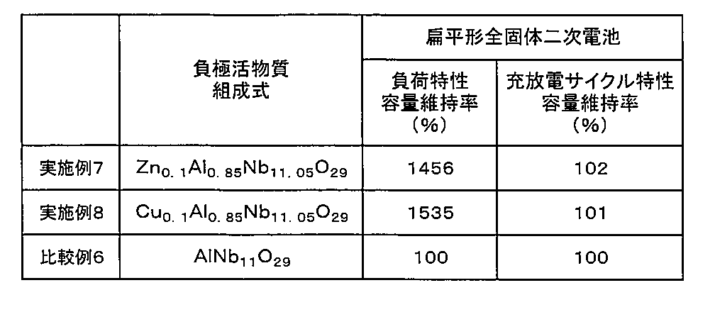
表2に示す通り、前記一般式(1)で表される酸化物を活物質とする負極を有する実施例7、8の扁平形全固体二次電池は、負荷特性評価時の容量維持率および充放電サイクル特性評価時の容量維持率のいずれもが高く、優れた負荷特性および充放電サイクル特性を有していた。
これに対し、元素M1を含有しない酸化物を活物質とする負極を用いた比較例6の電池は、負荷特性評価時の容量維持率および充放電サイクル特性評価時の容量維持率のいずれもが実施例の電池よりも低く、負荷特性および充放電サイクル特性が劣っていた。
実施例9
活物質を単斜晶型のCu0.21Al0.74Nb11.05O27.89に変更した以外は、実施例1と同様にしてシート状全固体二次電池を作製した。なお、活物質が単斜晶型の結晶であることは、実施例1と同様にして確認した。活物質の組成はICP-AES測定と酸素窒素分析装置による測定により求めた。
活物質を単斜晶型のCu0.21Al0.74Nb11.05O27.89に変更した以外は、実施例1と同様にしてシート状全固体二次電池を作製した。なお、活物質が単斜晶型の結晶であることは、実施例1と同様にして確認した。活物質の組成はICP-AES測定と酸素窒素分析装置による測定により求めた。
実施例10
各種金属酸化物の粉末(全て株式会社高純度化学より入手)の混合物を、カーボン製の容器に入れ、圧力が100Pa以下の真空雰囲気下で、1000℃で4時間焼成することで還元処理を施し、単斜晶型のCu0.14Al0.73Nb11.13O28.00を得た。活物質を、前記の単斜晶型のCu0.14Al0.73Nb11.13O28.00に変更した以外は、実施例1と同様にしてシート状全固体二次電池を作製した。なお、活物質が単斜晶型の結晶であることは、実施例1と同様にして確認した。活物質の組成はICP-AES測定と酸素窒素分析装置による測定により求めた。
各種金属酸化物の粉末(全て株式会社高純度化学より入手)の混合物を、カーボン製の容器に入れ、圧力が100Pa以下の真空雰囲気下で、1000℃で4時間焼成することで還元処理を施し、単斜晶型のCu0.14Al0.73Nb11.13O28.00を得た。活物質を、前記の単斜晶型のCu0.14Al0.73Nb11.13O28.00に変更した以外は、実施例1と同様にしてシート状全固体二次電池を作製した。なお、活物質が単斜晶型の結晶であることは、実施例1と同様にして確認した。活物質の組成はICP-AES測定と酸素窒素分析装置による測定により求めた。
実施例11
活物質を単斜晶型のFe0.20Al0.83Nb10.97O28.23に変更した以外は、実施例1と同様にしてシート状全固体二次電池を作製した。なお、活物質が単斜晶型の結晶であることは、実施例1と同様にして確認した。活物質の組成はICP-AES測定と酸素窒素分析装置による測定により求めた。
活物質を単斜晶型のFe0.20Al0.83Nb10.97O28.23に変更した以外は、実施例1と同様にしてシート状全固体二次電池を作製した。なお、活物質が単斜晶型の結晶であることは、実施例1と同様にして確認した。活物質の組成はICP-AES測定と酸素窒素分析装置による測定により求めた。
比較例7
活物質を、還元処理を施した単斜晶型のAl0.87Nb11.13O28.47に変更した以外は、実施例1と同様にしてシート状全固体二次電池を作製した。なお、活物質が単斜晶型の結晶であることは、実施例1と同様にして確認した。活物質の組成はICP-AES測定と酸素窒素分析装置による測定により求めた。
活物質を、還元処理を施した単斜晶型のAl0.87Nb11.13O28.47に変更した以外は、実施例1と同様にしてシート状全固体二次電池を作製した。なお、活物質が単斜晶型の結晶であることは、実施例1と同様にして確認した。活物質の組成はICP-AES測定と酸素窒素分析装置による測定により求めた。
実施例9~11および比較例7のシート状全固体二次電池について、放電下限電圧を0.18Vに変更した以外は実施例1の電池などと同様にして負荷特性および充放電サイクル特性を評価すると共に、電極中に含まれる活物質の重さで電池容量を除して、活物質重量あたりのエネルギー密度を求めた。
実施例9~11および比較例7のシート状全固体二次電池について、活物質の組成および物性を表3および表4に示し、前記の評価結果を表5に示す。なお、表3の「還元処理の有無」の欄において、「○」は還元処理を施したことを、「×」は還元処理を施していないことを、それぞれ意味している。
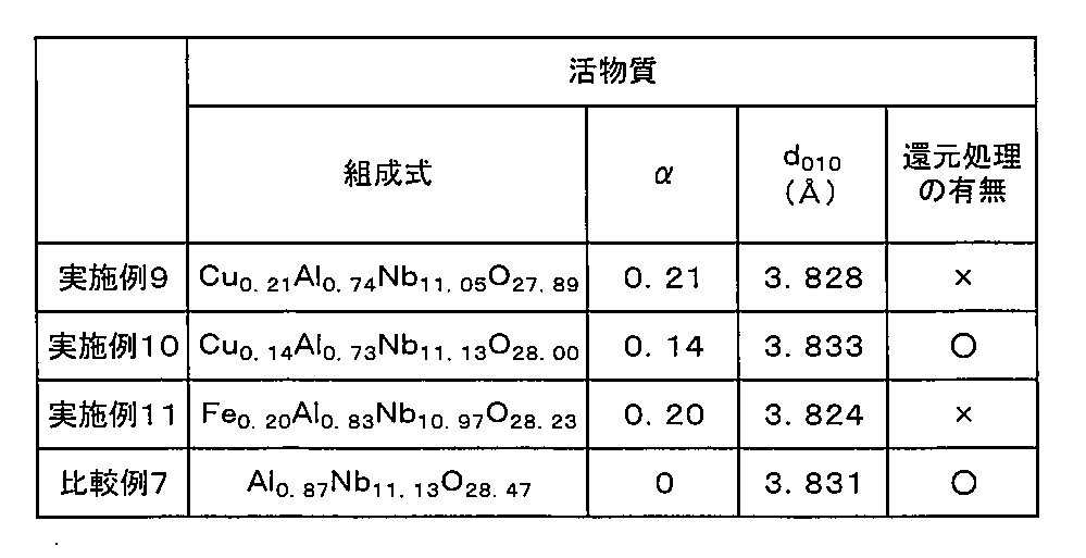
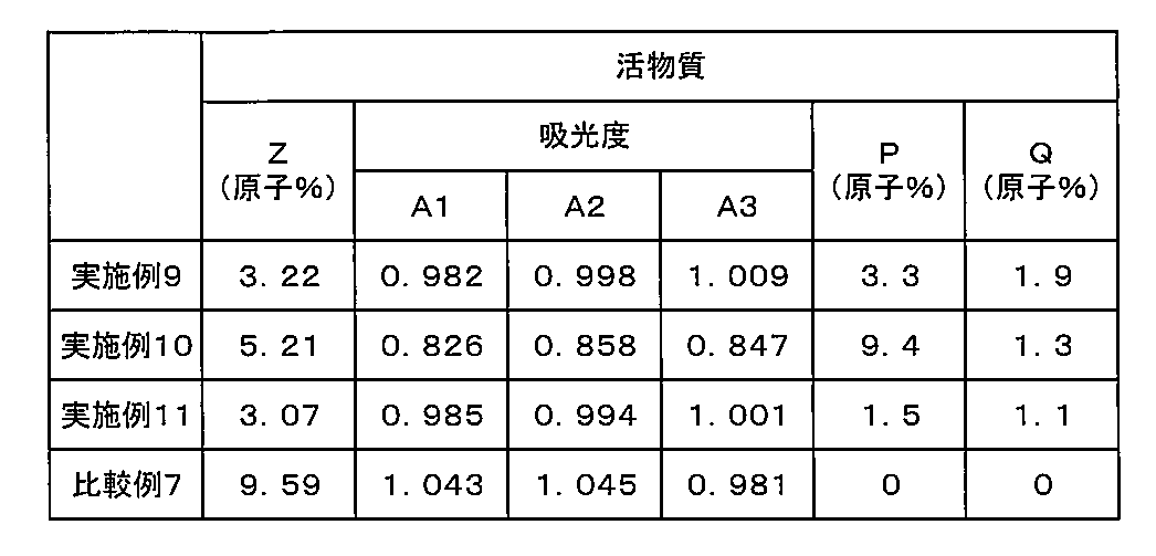
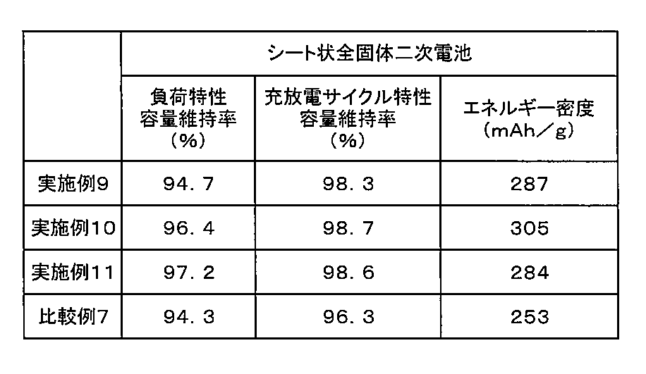
表3~表5に示す通り、前記一般式(1)で表される酸化物を活物質とする正極を有する実施例9~11のシート状全固体二次電池は、負荷特性評価時の容量維持率および充放電サイクル特性評価時の容量維持率のいずれもが高く、優れた負荷特性および充放電サイクル特性を有していたのに比べて、元素M1を含まないアルミニウムニオブ複合酸化物を活物質とする正極を有する比較例7の電池では負荷特性評価時の容量維持率および充放電サイクル特性評価時の容量維持率のいずれも劣っていた。
また、カーボン製容器内で還元処理を施し、Zの値が好適で、吸光度A1、A2およびA3が、A1<A2、かつA3<A2の関係を満たし、原子比率Pと原子比率QとがP>Qの関係を満たす前記酸化物を活物質とする正極を有する実施例10の電池は、還元処理を施していない前記酸化物を活物質とする正極を有する実施例9、11の電池や、元素M1を含まないアルミニウムニオブ複合酸化物を活物質とする正極を有する比較例7の電池に比べて、エネルギー密度が大きくなった。
本発明は、その趣旨を逸脱しない範囲で、前記以外の形態としても実施が可能である。本出願に開示された実施形態は一例であって、本発明は、これらの実施形態には限定されない。本発明の範囲は、前記の明細書の記載よりも、添付されている請求の範囲の記載を優先して解釈され、請求の範囲と均等の範囲内での全ての変更は、請求の範囲に含まれる。
本発明の電気化学素子は、従来から知られている非水電解質(非水電解液やゲル状電解質)を有する二次電池や、水系電解質を有する二次電池、全固体二次電池、スーパーキャパシタと同様の用途に適用できる。また、本発明の電気化学素子用電極は本発明の電気化学素子を構成でき、本発明の電気化学素子用活物質および本発明の電気化学素子用電極材料は、本発明の電気化学素子用電極を構成できる。
なお、本発明の電気化学素子は、優れた負荷特性を有していることから、このような特性が要求されることの多い用途、例えば、産業用機器や移動体(電気自動車やハイブリッドカー、電動バイクなどの車両、船舶、潜水艦、ラジコン、ロケットや人工衛星などの飛翔体、ドローンなど)の電源用途などに好適である。また、移動体の中には、ハイブリッドカーのように、回生エネルギーによって使用している電池の充電を行うものがあるが、この場合、充電電流・電圧が安定しない場合があるため、電池内において元素Aのデンドライトが発生しやすく、これによって電池劣化が生じる虞がある。しかしながら、本発明の電気化学素子は、元素Aのデンドライトが生じ難い酸化物を活物質としていることから、回生エネルギーによって充電を行っても元素Aのデンドライトに起因する劣化を抑制することが可能であり、こうした充電を行うことのある移動体などにも好ましく適用できる。
1、100 電気化学素子(二次電池)
10 正極
20 負極
30 固体電解質層またはセパレータ
40 外装缶
50 封口缶
60 ガスケット
200 電極体
300 正極外部端子
400 負極外部端子
500 ラミネートフィルム外装体
10 正極
20 負極
30 固体電解質層またはセパレータ
40 外装缶
50 封口缶
60 ガスケット
200 電極体
300 正極外部端子
400 負極外部端子
500 ラミネートフィルム外装体
Claims (12)
- 単斜晶型の結晶構造を有しており、下記一般式(1)を満たす酸化物を含むことを特徴とする電気化学素子用電極活物質。
AyM1 αAlx-αNb12-x-zM2 zO29-δ (1)
〔前記一般式(1)中、AはLiおよびNaのうちの少なくとも一方の元素、M1はFe、Mn、Zn、Cu、Ag、Mg、Ca、Sr、Ba、Co、Eu、Y、Bi、La、Ce、Nd、SmおよびGdよりなる群から選択される少なくとも1種の元素、M2はK、Ti、Ni、Zr、V、Mo、TaおよびWよりなる群から選択される少なくとも1種の元素であり、0<x≦1.1、0≦y≦24、0≦z≦2、-1≦δ≦2、0<α≦0.4xである。〕 - 前記一般式(1)において、元素M1がFe、ZnおよびCuよりなる群から選択される少なくとも1種の元素であり、0<δ≦2である請求項1に記載の電気化学素子用電極活物質。
- 前記一般式(1)で表される酸化物における全Nbに対するNb4+の比率Z(原子%)が、3.5≦Z≦30である請求項1または2に記載の電気化学素子用電極活物質。
- 波長500nmにおける吸光度をA1、波長600nmにおける吸光度をA2、および波長700nmにおける吸光度をA3としたとき、A1<A2の関係を満たし、かつA3<A2の関係を満たす請求項1または2に記載の電気化学素子用電極活物質。
- X線光電子分光分析によって求められるNbに対する元素M1の原子比率Pと、誘導結合プラズマ発光分光分析によって求められるNbに対する元素M1の原子比率Qとが、P>Qの関係を満たす請求項1~4のいずれかに記載の電気化学素子用電極活物質。
- 前記一般式(1)で表される酸化物が、下記一般式(2)を満たすものである請求項1に記載の電気化学素子用電極活物質。
M1 αAl1-1.5αNb11+0.5αO29-δ (2)
〔前記一般式(2)中、M1はZnおよびCuのうちの少なくとも一方の元素であり、0<α≦0.4、0≦δ≦0.5αである。〕 - 請求項1~6のいずれかに記載の電気化学素子用電極活物質を製造する方法であって、
前記一般式(1)で表される酸化物またはその前駆体を、真空雰囲気下において、カーボン製の容器内で焼成することを特徴とする電気化学素子用電極活物質の製造方法。 - 請求項1~6のいずれかに記載の電気化学素子用電極活物質を含有することを特徴とする電気化学素子用電極材料。
- 固体電解質をさらに含有する請求項8に記載の電気化学素子用電極材料。
- 請求項1~6のいずれかに記載の電気化学素子用電極活物質を含有するか、または請求項8もしくは9に記載の電気化学素子用電極材料を含有することを特徴とする電気化学素子用電極。
- 正極および負極を有し、前記正極および前記負極のいずれか一方が請求項10に記載の電気化学素子用電極であることを特徴とする電気化学素子。
- 請求項11に記載の電気化学素子を有することを特徴とする移動体。
Priority Applications (5)
| Application Number | Priority Date | Filing Date | Title |
|---|---|---|---|
| CN202180029604.7A CN115428191A (zh) | 2020-10-16 | 2021-09-17 | 电化学元件用电极活性物质及其制造方法、电化学元件用电极材料、电化学元件用电极、电化学元件以及移动体 |
| EP21879824.7A EP4230586A1 (en) | 2020-10-16 | 2021-09-17 | Electrode active material for electrochemical element and method for producing same, electrode material for electrochemical element, electrode for electrochemical element, electrochemical element, and mobile object |
| US17/924,268 US20230178720A1 (en) | 2020-10-16 | 2021-09-17 | Electrode active material for electrochemical element, method for manufacturing the same, electrode material for electrochemical element, electrode for electrochemical element, electrochemical element, and movable body |
| JP2022519369A JP7168819B2 (ja) | 2020-10-16 | 2021-09-17 | 電気化学素子用電極活物質およびその製造方法、電気化学素子用電極材料、電気化学素子用電極、電気化学素子、並びに移動体 |
| JP2022171912A JP2023001199A (ja) | 2020-10-16 | 2022-10-27 | 電気化学素子用電極活物質およびその製造方法、電気化学素子用電極材料、電気化学素子用電極、電気化学素子、並びに移動体 |
Applications Claiming Priority (2)
| Application Number | Priority Date | Filing Date | Title |
|---|---|---|---|
| JP2020174408 | 2020-10-16 | ||
| JP2020-174408 | 2020-10-16 |
Publications (1)
| Publication Number | Publication Date |
|---|---|
| WO2022080083A1 true WO2022080083A1 (ja) | 2022-04-21 |
Family
ID=81209161
Family Applications (1)
| Application Number | Title | Priority Date | Filing Date |
|---|---|---|---|
| PCT/JP2021/034246 WO2022080083A1 (ja) | 2020-10-16 | 2021-09-17 | 電気化学素子用電極活物質およびその製造方法、電気化学素子用電極材料、電気化学素子用電極、電気化学素子、並びに移動体 |
Country Status (5)
| Country | Link |
|---|---|
| US (1) | US20230178720A1 (ja) |
| EP (1) | EP4230586A1 (ja) |
| JP (2) | JP7168819B2 (ja) |
| CN (1) | CN115428191A (ja) |
| WO (1) | WO2022080083A1 (ja) |
Cited By (2)
| Publication number | Priority date | Publication date | Assignee | Title |
|---|---|---|---|---|
| WO2023140311A1 (ja) * | 2022-01-21 | 2023-07-27 | マクセル株式会社 | 全固体電池用正極、並びに全固体電池およびその製造方法 |
| WO2024070429A1 (ja) * | 2022-09-29 | 2024-04-04 | 太陽誘電株式会社 | 負極活物質および全固体電池 |
Families Citing this family (3)
| Publication number | Priority date | Publication date | Assignee | Title |
|---|---|---|---|---|
| GB202013576D0 (en) | 2020-08-28 | 2020-10-14 | Echion Tech Limited | Active electrode material |
| KR102646793B1 (ko) * | 2021-07-23 | 2024-03-13 | 삼성전자주식회사 | 커패시터, 이를 포함하는 전자 소자, 및 이의 제조방법 |
| CN117117174B (zh) * | 2023-10-25 | 2024-03-19 | 宁波容百新能源科技股份有限公司 | 钠离子电池正极材料及其制备方法和应用 |
Citations (10)
| Publication number | Priority date | Publication date | Assignee | Title |
|---|---|---|---|---|
| JP2017134972A (ja) * | 2016-01-27 | 2017-08-03 | 太平洋セメント株式会社 | 二次電池用負極活物質の製造方法 |
| CN107742716A (zh) * | 2017-10-12 | 2018-02-27 | 海南大学 | 一种锂离子电池的电极材料及其制备方法 |
| JP2018160365A (ja) | 2017-03-22 | 2018-10-11 | 株式会社東芝 | 活物質、電極、二次電池、電池パック、及び車両 |
| JP2019053945A (ja) | 2017-09-19 | 2019-04-04 | 株式会社東芝 | 活物質、電極、二次電池、電池パック、及び車両 |
| CN109904441A (zh) * | 2018-12-29 | 2019-06-18 | 瑞声科技(新加坡)有限公司 | 一种锂离子电池负极材料、非水电解质锂离子电池及其制备方法 |
| JP2019160729A (ja) | 2018-03-16 | 2019-09-19 | 株式会社東芝 | 活物質、電極、二次電池、電池パック、及び車両 |
| WO2020070958A1 (ja) | 2018-10-01 | 2020-04-09 | パナソニックIpマネジメント株式会社 | ハロゲン化物固体電解質材料およびこれを用いた電池 |
| WO2020070955A1 (ja) | 2018-10-01 | 2020-04-09 | パナソニックIpマネジメント株式会社 | ハロゲン化物固体電解質材料およびこれを用いた電池 |
| WO2021074592A1 (en) | 2019-10-18 | 2021-04-22 | Echion Technologies Limited | Active electrode material |
| JP2021082420A (ja) | 2019-11-15 | 2021-05-27 | 昭和電工マテリアルズ株式会社 | 負極活物質、負極、電池セル |
-
2021
- 2021-09-17 JP JP2022519369A patent/JP7168819B2/ja active Active
- 2021-09-17 EP EP21879824.7A patent/EP4230586A1/en active Pending
- 2021-09-17 US US17/924,268 patent/US20230178720A1/en active Pending
- 2021-09-17 CN CN202180029604.7A patent/CN115428191A/zh active Pending
- 2021-09-17 WO PCT/JP2021/034246 patent/WO2022080083A1/ja unknown
-
2022
- 2022-10-27 JP JP2022171912A patent/JP2023001199A/ja active Pending
Patent Citations (11)
| Publication number | Priority date | Publication date | Assignee | Title |
|---|---|---|---|---|
| JP2017134972A (ja) * | 2016-01-27 | 2017-08-03 | 太平洋セメント株式会社 | 二次電池用負極活物質の製造方法 |
| JP2018160365A (ja) | 2017-03-22 | 2018-10-11 | 株式会社東芝 | 活物質、電極、二次電池、電池パック、及び車両 |
| JP2019053945A (ja) | 2017-09-19 | 2019-04-04 | 株式会社東芝 | 活物質、電極、二次電池、電池パック、及び車両 |
| CN107742716A (zh) * | 2017-10-12 | 2018-02-27 | 海南大学 | 一种锂离子电池的电极材料及其制备方法 |
| JP2019160729A (ja) | 2018-03-16 | 2019-09-19 | 株式会社東芝 | 活物質、電極、二次電池、電池パック、及び車両 |
| WO2020070958A1 (ja) | 2018-10-01 | 2020-04-09 | パナソニックIpマネジメント株式会社 | ハロゲン化物固体電解質材料およびこれを用いた電池 |
| WO2020070955A1 (ja) | 2018-10-01 | 2020-04-09 | パナソニックIpマネジメント株式会社 | ハロゲン化物固体電解質材料およびこれを用いた電池 |
| CN109904441A (zh) * | 2018-12-29 | 2019-06-18 | 瑞声科技(新加坡)有限公司 | 一种锂离子电池负极材料、非水电解质锂离子电池及其制备方法 |
| WO2021074592A1 (en) | 2019-10-18 | 2021-04-22 | Echion Technologies Limited | Active electrode material |
| WO2021074594A1 (en) * | 2019-10-18 | 2021-04-22 | Echion Technologies Limited | Li/na-ion battery anode materials |
| JP2021082420A (ja) | 2019-11-15 | 2021-05-27 | 昭和電工マテリアルズ株式会社 | 負極活物質、負極、電池セル |
Non-Patent Citations (5)
| Title |
|---|
| ACS APPLIED MATERIAL INTERFACES, vol. 11, 2019, pages 6086 - 6096 |
| ELECTROCHEMISTRY COMMUNICATIONS, vol. 25, 2012, pages 39 - 42 |
| JOURNAL OF MATERIALS CHEMISTRY A, vol. 7, 2019, pages 25537 - 25547 |
| JOURNAL OF POWER SOURCES, vol. 328, 2016, pages 336 - 344 |
| XIAOMING LOU, RENJIE LI, XIANGZHEN ZHU, LIJIE LUO, YONGJUN CHEN, CHUNFU LIN, HONGLIANG LI, X. S. ZHAO: "New Anode Material for Lithium-Ion Batteries: Aluminum Niobate (AlNb 11 O 29 )", APPLIED MATERIALS & INTERFACES, AMERICAN CHEMICAL SOCIETY, US, vol. 11, no. 6, 13 February 2019 (2019-02-13), US , pages 6089 - 6096, XP055761577, ISSN: 1944-8244, DOI: 10.1021/acsami.8b20246 * |
Cited By (2)
| Publication number | Priority date | Publication date | Assignee | Title |
|---|---|---|---|---|
| WO2023140311A1 (ja) * | 2022-01-21 | 2023-07-27 | マクセル株式会社 | 全固体電池用正極、並びに全固体電池およびその製造方法 |
| WO2024070429A1 (ja) * | 2022-09-29 | 2024-04-04 | 太陽誘電株式会社 | 負極活物質および全固体電池 |
Also Published As
| Publication number | Publication date |
|---|---|
| JP2023001199A (ja) | 2023-01-04 |
| JPWO2022080083A1 (ja) | 2022-04-21 |
| US20230178720A1 (en) | 2023-06-08 |
| JP7168819B2 (ja) | 2022-11-09 |
| EP4230586A1 (en) | 2023-08-23 |
| CN115428191A (zh) | 2022-12-02 |
Similar Documents
| Publication | Publication Date | Title |
|---|---|---|
| WO2022080083A1 (ja) | 電気化学素子用電極活物質およびその製造方法、電気化学素子用電極材料、電気化学素子用電極、電気化学素子、並びに移動体 | |
| US11362366B2 (en) | Secondary battery composite electrolyte, secondary battery, and battery pack | |
| US11329316B2 (en) | Secondary battery composite electrolyte, secondary battery, and battery pack | |
| CN112313821B (zh) | 正极活性物质及电池 | |
| JP7028073B2 (ja) | 非水系電解質二次電池用正極活物質、非水系電解質二次電池 | |
| CN111741928B (zh) | 金属复合氢氧化物及其制造方法、非水电解质二次电池用正极活性物质及其制造方法、以及非水电解质二次电池 | |
| JP7345263B2 (ja) | 全固体リチウム二次電池の製造方法 | |
| CN112335076A (zh) | 电极、电池及电池包 | |
| CN111770896A (zh) | 金属复合氢氧化物及其制造方法、非水电解质二次电池用正极活性物质及其制造方法、以及非水电解质二次电池 | |
| JP7267163B2 (ja) | 全固体電池用正極および全固体電池 | |
| JP6963866B2 (ja) | 全固体電池用負極および全固体電池 | |
| JP7401359B2 (ja) | 全固体電池用電極および全固体電池 | |
| JP7473527B2 (ja) | リチウムイオン二次電池用正極活物質、リチウムイオン二次電池用正極活物質の製造方法、リチウムイオン二次電池 | |
| JP7469920B2 (ja) | 全固体電池用正極および全固体電池 | |
| WO2022190933A1 (ja) | 電気化学素子用電極活物質、電気化学素子用電極材料、電気化学素子用電極、電気化学素子および移動体 | |
| US20240132369A1 (en) | Electrode active material for electrochemical element, electrode material for electrochemical element, electrode for electrochemical element, electrochemical element, and movable body | |
| JP2022048664A (ja) | 全固体電池用正極および全固体電池 | |
| WO2019189679A1 (ja) | 非水系電解質二次電池用正極活物質 | |
| CN111741927A (zh) | 金属复合氢氧化物及其制造方法、非水电解质二次电池用正极活性物质及其制造方法、以及非水电解质二次电池 | |
| WO2023171541A1 (ja) | 非水電解質二次電池用電極および非水電解質二次電池 | |
| JP7457688B2 (ja) | リチウムイオン二次電池用正極活物質の製造方法 | |
| WO2023189818A1 (ja) | 全固体電池用電極および全固体電池 | |
| WO2022054665A1 (ja) | 非水電解質二次電池用負極および非水電解質二次電池 | |
| EP4112561A1 (en) | Lithium metal composite oxide, positive electrode active material for lithium secondary batteries, positive electrode for lithium secondary batteries, and lithium secondary battery | |
| JP7421985B2 (ja) | 全固体二次電池およびその製造方法 |
Legal Events
| Date | Code | Title | Description |
|---|---|---|---|
| ENP | Entry into the national phase |
Ref document number: 2022519369 Country of ref document: JP Kind code of ref document: A |
|
| 121 | Ep: the epo has been informed by wipo that ep was designated in this application |
Ref document number: 21879824 Country of ref document: EP Kind code of ref document: A1 |
|
| NENP | Non-entry into the national phase |
Ref country code: DE |
|
| ENP | Entry into the national phase |
Ref document number: 2021879824 Country of ref document: EP Effective date: 20230516 |