WO2022044557A1 - フォトマスク、露光方法、樹脂パターンの製造方法及びフォトマスクの製造方法 - Google Patents
フォトマスク、露光方法、樹脂パターンの製造方法及びフォトマスクの製造方法 Download PDFInfo
- Publication number
- WO2022044557A1 WO2022044557A1 PCT/JP2021/025672 JP2021025672W WO2022044557A1 WO 2022044557 A1 WO2022044557 A1 WO 2022044557A1 JP 2021025672 W JP2021025672 W JP 2021025672W WO 2022044557 A1 WO2022044557 A1 WO 2022044557A1
- Authority
- WO
- WIPO (PCT)
- Prior art keywords
- photomask
- photosensitive layer
- layer
- mass
- group
- Prior art date
- Legal status (The legal status is an assumption and is not a legal conclusion. Google has not performed a legal analysis and makes no representation as to the accuracy of the status listed.)
- Ceased
Links
Images


Classifications
-
- G—PHYSICS
- G03—PHOTOGRAPHY; CINEMATOGRAPHY; ANALOGOUS TECHNIQUES USING WAVES OTHER THAN OPTICAL WAVES; ELECTROGRAPHY; HOLOGRAPHY
- G03F—PHOTOMECHANICAL PRODUCTION OF TEXTURED OR PATTERNED SURFACES, e.g. FOR PRINTING, FOR PROCESSING OF SEMICONDUCTOR DEVICES; MATERIALS THEREFOR; ORIGINALS THEREFOR; APPARATUS SPECIALLY ADAPTED THEREFOR
- G03F1/00—Originals for photomechanical production of textured or patterned surfaces, e.g., masks, photo-masks, reticles; Mask blanks or pellicles therefor; Containers specially adapted therefor; Preparation thereof
- G03F1/50—Mask blanks not covered by G03F1/20 - G03F1/34; Preparation thereof
-
- G—PHYSICS
- G03—PHOTOGRAPHY; CINEMATOGRAPHY; ANALOGOUS TECHNIQUES USING WAVES OTHER THAN OPTICAL WAVES; ELECTROGRAPHY; HOLOGRAPHY
- G03F—PHOTOMECHANICAL PRODUCTION OF TEXTURED OR PATTERNED SURFACES, e.g. FOR PRINTING, FOR PROCESSING OF SEMICONDUCTOR DEVICES; MATERIALS THEREFOR; ORIGINALS THEREFOR; APPARATUS SPECIALLY ADAPTED THEREFOR
- G03F7/00—Photomechanical, e.g. photolithographic, production of textured or patterned surfaces, e.g. printing surfaces; Materials therefor, e.g. comprising photoresists; Apparatus specially adapted therefor
- G03F7/20—Exposure; Apparatus therefor
-
- H—ELECTRICITY
- H05—ELECTRIC TECHNIQUES NOT OTHERWISE PROVIDED FOR
- H05K—PRINTED CIRCUITS; CASINGS OR CONSTRUCTIONAL DETAILS OF ELECTRIC APPARATUS; MANUFACTURE OF ASSEMBLAGES OF ELECTRICAL COMPONENTS
- H05K3/00—Apparatus or processes for manufacturing printed circuits
- H05K3/22—Secondary treatment of printed circuits
- H05K3/28—Applying non-metallic protective coatings
Definitions
- This disclosure relates to a photomask, an exposure method, a resin pattern manufacturing method, and a photomask manufacturing method.
- Patent Document 1 discloses a photomask provided with a release layer having a thicker film than a light-shielding pattern.
- Patent Document 1 When the photomask disclosed in Patent Document 1 is brought into contact with the photosensitive layer, the peeling layer adheres to the photosensitive layer, and the light-shielding pattern does not adhere to the photosensitive layer. As a result, the photomask can be smoothly separated from the photosensitive layer. However, according to the photomask disclosed in Patent Document 1, the distance between the photomask and the photosensitive layer becomes long, so that the resolution is lowered.
- Patent Document 2 describes a photomask for performing exposure in contact with a resist, the photomask having a rough surface region on the surface on the side in contact with the resist. The mask is disclosed.
- Patent Document 1 Japanese Patent Application Laid-Open No. 8-6253
- Patent Document 2 Japanese Patent Application Laid-Open No. 2006-18190
- the distance between the photomask and the photosensitive layer is shortened.
- the linearity of the obtained pattern may decrease.
- it is required to improve the linearity of the obtained pattern while reducing the adhesiveness of the photomask to an object to be contacted such as a photosensitive layer.
- the present disclosure includes the following aspects.
- a transparent support having a first surface and a second surface opposite to the first surface, and a light-shielding layer arranged on a part of the first surface of the transparent support.
- the surface roughness Rz of the exposed portion of the first surface is 0.1 ⁇ m to 0.5 ⁇ m
- the surface roughness Rz of the light-shielding layer is 0.1 ⁇ m to 0.5 ⁇ m. .. ⁇ 2>
- a transparent support having a first surface and a second surface opposite to the first surface, and a light-shielding layer arranged on a part of the first surface of the transparent support.
- a photomask comprising the first surface of the transparent support and a protective layer arranged on the light-shielding layer, and the surface roughness Rz of the protective layer is 0.1 ⁇ m to 0.5 ⁇ m. .. ⁇ 4>
- the photomask according to ⁇ 3>, wherein the surface roughness Ra of the protective layer is 5 nm to 50 nm.
- the protective layer contains an organic polymer compound.
- ⁇ 6> The photomask according to ⁇ 5>, wherein the organic polymer compound contains a structural unit derived from urethane acrylate.
- the protective layer contains a fluorine atom-containing compound.
- the transparent support is flat quartz glass.
- the light-shielding layer contains chromium.
- the photomask according to any one of ⁇ 1> to ⁇ 9> is prepared, and the photomask is brought into contact with the photosensitive layer to expose the photosensitive layer through the photomask. And exposure methods including.
- the photomask according to any one of ⁇ 1> to ⁇ 9> is prepared, and the photomask is brought into contact with the photosensitive layer to expose the photosensitive layer through the photomask.
- a method for producing a resin pattern which comprises the above, and the development of the exposed photosensitive layer to form a resin pattern.
- Preparing the photomask according to any one of ⁇ 1> to ⁇ 9> preparing a laminate containing a photosensitive layer and a temporary support in this order, and the above.
- the photomask is brought into contact with the temporary support to expose the photosensitive layer through the photomask and the temporary support, and the exposed photosensitive layer is developed to form a resin pattern. And how to make a resin pattern including.
- ⁇ 13> Preparing the photomask according to any one of ⁇ 1> to ⁇ 9>, preparing a laminate containing a photosensitive layer and a temporary support in this order, and the above.
- the temporary support is peeled off to expose the surface of the photosensitive layer, and the photomask is brought into contact with the surface of the photosensitive layer exposed by the peeling of the temporary support, and the photomask is used to expose the surface of the photosensitive layer.
- a method for producing a resin pattern which comprises exposing the photosensitive layer and developing the exposed photosensitive layer to form a resin pattern.
- the test load when the laminate further includes a resin layer between the photosensitive layer and the temporary support and the indentation depth is 1/10 of the thickness of the resin layer in the indentation test.
- the universal hardness of the resin layer measured based on the above is 5.0 N / mm 2 or more, and in exposing the photosensitive layer, the photosensitive layer is exposed via the photo mask and the resin layer.
- ⁇ 16> When the universal hardness of the photosensitive layer measured based on the test load when the indentation depth is 1/10 of the thickness of the photosensitive layer in the indentation test is 5.0 N / mm 2 or more.
- ⁇ 17> A transparent support having a first surface and a second surface opposite to the first surface, and a light-shielding layer arranged on a part of the first surface of the transparent support. By preparing a laminate containing the above and blasting the laminate, the surface roughness Rz of the exposed portion of the first surface is adjusted to 0.1 ⁇ m to 0.5 ⁇ m.
- a method for producing a photomask which comprises adjusting the surface roughness Rz of the light-shielding layer to 0.1 ⁇ m to 0.5 ⁇ m.
- a transparent support having a first surface and a second surface opposite to the first surface, and a light-shielding layer arranged on a part of the first surface of the transparent support.
- a photomask in which the adhesiveness to an object to be contacted in contact exposure is reduced and a pattern having excellent linearity is formed.
- an exposure method using the above photomask is provided.
- a method for producing a resin pattern using the above photomask is provided.
- the numerical range represented by using “-" means a range including the numerical values before and after "-" as the lower limit value and the upper limit value.
- the upper limit value or the lower limit value representing a certain numerical range may be replaced with the upper limit value or the lower limit value representing another numerical range.
- the upper limit value or the lower limit value representing a certain numerical range may be replaced with the value shown in the examples.
- (meth) acrylic means acrylic, methacrylic or both acrylic and methacrylic.
- (meth) acrylate means acrylate, methacrylate or both acrylate and methacrylate.
- the amount of each component in the composition is the total amount of the plurality of applicable substances present in the composition when a plurality of the substances corresponding to each component are present in the composition, unless otherwise specified. means.
- process is included in this term not only as an independent process but also as long as the intended purpose of the process is achieved even if it cannot be clearly distinguished from other processes.
- the notation that does not describe substitution or non-substitution includes a group having no substituent and a group having a substituent.
- an "alkyl group” includes not only an alkyl group having no substituent (ie, an unsubstituted alkyl group) but also an alkyl group having a substituent (ie, a substituted alkyl group).
- exposure includes not only exposure using light but also drawing using particle beams such as electron beams and ion beams, unless otherwise specified.
- the light used for exposure generally include emission line spectra of mercury lamps, far ultraviolet rays typified by excimer lasers, extreme ultraviolet rays (EUV light), X-rays, and active rays (active energy rays) such as electron beams. ..
- the chemical structural formula may be described as a simplified structural formula omitting a hydrogen atom.
- the weight average molecular weight (Mw) and the number average molecular weight (Mn) are detected and standardized using a gel permeation chromatography (GPC) analyzer, tetrahydrofuran as a solvent and a differential refractometer, unless otherwise specified. It is a molecular weight converted using polystyrene as a substance.
- GPC analyzer The columns used in the GPC analyzer are "TSKgel GMHxL, TSKgel G4000HxL” and “TSKgel G2000HxL” (both are trade names manufactured by Tosoh Corporation).
- ordinal numbers are terms used to distinguish the components, and do not limit the number of components and the superiority or inferiority of the components.
- the photomask according to the embodiment of the present disclosure includes a transparent support having a first surface and a second surface opposite to the first surface, and one of the first surfaces of the transparent support.
- a light-shielding layer is included on the portion.
- the surface roughness Rz of the exposed portion of the first surface is 0.1 ⁇ m to 0.5 ⁇ m
- the surface roughness Rz of the light-shielding layer is 0.1 ⁇ m to 0.5 ⁇ m.
- FIG. 1 is a schematic cross-sectional view showing a layer structure of a photomask according to the first embodiment.
- FIG. 2 is a schematic cross-sectional view showing the layer structure of the photomask according to the first embodiment in contact with the photosensitive layer.
- the photomask 100 shown in FIG. 1 includes a transparent support 10 and a light-shielding layer 20.
- the transparent support 10 has a first surface 10a and a second surface 10b. A part of the first surface 10a is covered with the light-shielding layer 20.
- the surface roughness Rz of the exposed portion of the first surface 10a (in other words, the portion of the first surface 10a that is not covered by the light-shielding layer 20) is 0.1 ⁇ m to 0.5 ⁇ m.
- the second surface 10b is a surface located on the opposite side of the first surface 10a.
- the light-shielding layer 20 is arranged on a part of the first surface 10a of the transparent support 10.
- the surface roughness Rz of the light-shielding layer 20 is 0.1 ⁇ m to 0.5 ⁇ m.
- the photomask 100 is used in contact with the photosensitive layer 200.
- the surface roughness Rz of the portion of the photomask 100 in contact with the photosensitive layer 200 is adjusted to 0.1 ⁇ m to 0.5 ⁇ m.
- the light-shielding layer 20 of the photomask 100 is in contact with the photosensitive layer 200.
- the first surface 10a of the photomask 100 is not in contact with the photosensitive layer 200.
- the matter shown in FIG. 2 does not exclude that the first surface 10a of the photomask 100 comes into contact with the photosensitive layer 200.
- the first surface 10a of the photomask 100 may come into contact with the photosensitive layer 200.
- the photosensitive layer 200 is exposed via the photomask 100.
- the light emitted from the light source passes through the portion of the transparent support 10 that is not covered by the light-shielding layer 20.
- the photomask 100 is peeled off from the photosensitive layer 200.
- the portion not covered by the light-shielding layer of the transparent support may be referred to as a “light transmitting portion”.
- the portion of the photomask according to the first embodiment having a surface roughness Rz of 0.1 ⁇ m to 0.5 ⁇ m (for example,).
- the transparent support and the light-shielding layer come into contact with the object to be contacted (for example, the photosensitive layer).
- the surface roughness Rz of the portion in contact with the object to be contacted is 0.1 ⁇ m to 0.5 ⁇ m, so that the slipperiness of the photomask is improved and light is scattered during exposure. Is suppressed.
- the adhesiveness of the photomask to the photosensitive layer is reduced.
- the linearity of the obtained pattern is improved. Therefore, according to the above-described embodiment of the present disclosure, there is provided a photomask in which the adhesiveness to an object to be contacted in contact exposure is reduced and a pattern having excellent linearity is formed.
- the photomask according to the first embodiment will be specifically described.
- the photomask according to the first embodiment includes a transparent support having a first surface and a second surface opposite to the first surface.
- transparent means that the transmittance of light in the wavelength range of 350 nm to 700 nm is 50% or more.
- the transmittance of the light is preferably 80% or more, more preferably 90% or more, and particularly preferably 95% or more.
- the transmittance of the light may be 100% or less or less than 100%.
- the light transmittance is measured using an ultraviolet-visible spectrophotometer (for example, UV1800 manufactured by Shimadzu Corporation).
- UV1800 ultraviolet-visible spectrophotometer
- the transparent support examples include quartz glass, soda lime glass, and PET film.
- the transparent support is preferably quartz glass from the viewpoint of transmittance and dimensional accuracy.
- the shape of the transparent support is preferably a flat plate.
- the thickness of the transparent support is not limited. From the viewpoint of strength, the thickness of the transparent support is preferably 0.5 mm or more, more preferably 1 mm or more, and particularly preferably 2 mm or more. From the viewpoint of transmittance, the thickness of the transparent support is preferably 5 mm or less, more preferably 4 mm or less, and particularly preferably 3 mm or less. The thickness of the transparent support is measured by arithmetically averaging the thickness of the transparent support measured at 10 points.
- the first surface of the transparent support is the surface on which the light-shielding layer is arranged.
- the first surface of the transparent support faces the light-shielding layer.
- the surface roughness Rz of the exposed portion of the first surface is 0.1 ⁇ m to 0.5 ⁇ m.
- the "exposed portion of the first surface” means a portion of the first surface that is not covered by the light-shielding layer.
- the surface roughness Rz of the exposed portion of the first surface is preferably 0.15 ⁇ m or more, preferably 0.2 ⁇ m or more, from the viewpoint of reducing the adhesiveness of the photomask to the contacted object in contact exposure. It is more preferably 0.25 ⁇ m or more, and particularly preferably 0.25 ⁇ m or more.
- the surface roughness Rz of the exposed portion of the first surface is preferably 0.45 ⁇ m or less, more preferably 0.4 ⁇ m or less, and more preferably 0.35 ⁇ m or less, from the viewpoint of improving the linearity of the pattern. It is particularly preferable to have.
- surface roughness Rz is a value expressed in micrometers, which is the total value of the maximum value of the height of the peak and the maximum value of the depth of the valley observed in the roughness curve at the reference length. means.
- a surface roughness measuring device for example, VK-X1000 manufactured by KEYENCE CORPORATION
- a roughness curve on the surface of the object to be measured and an average line of the roughness curves are created. Extract the part corresponding to the reference length from the roughness curve.
- the maximum value of the height of the mountain that is, the height from the average line to the summit
- the maximum value of the depth of the valley that is, the height from the average line to the bottom of the valley
- the surface roughness Ra of the exposed portion of the first surface is preferably 5 nm to 50 nm.
- the slipperiness of the photomask is improved, and the adhesiveness of the photomask to the contacted object in contact exposure is reduced.
- the surface roughness Ra of the exposed portion of the first surface is 50 nm or less, light scattering during exposure is suppressed and the linearity of the obtained pattern is improved.
- the surface roughness Ra of the exposed portion of the first surface is preferably 10 nm or more, more preferably 15 nm or more, and more preferably 20 nm from the viewpoint of reducing the adhesiveness of the photomask to the object to be contacted in contact exposure. The above is particularly preferable.
- the surface roughness Ra of the exposed portion of the first surface is preferably 40 nm or less, more preferably 35 nm or less, and particularly preferably 30 nm or less, from the viewpoint of improving the linearity of the pattern.
- surface roughness Ra means a value expressed in nanometers of the arithmetic mean roughness calculated based on the roughness curve at the reference length.
- a surface roughness measuring device for example, VK-X1000 manufactured by KEYENCE CORPORATION
- a roughness curve on the surface of the object to be measured and an average line of the roughness curves are created. Extract the part corresponding to the reference length from the roughness curve.
- the surface roughness Ra is measured by obtaining the arithmetic mean roughness based on the extracted roughness curve.
- the formula for calculating the arithmetic mean roughness (Ra) is described in "JIS B 0601: 2017".
- the photomask according to the first embodiment includes a light-shielding layer.
- light shielding means that the transmittance of light in the wavelength range of 350 nm to 700 nm is 1% or less.
- the transmittance of the light is preferably 0.1% or less, more preferably 0.05% or less, and particularly preferably 0.01% or less.
- the light transmittance is measured using an ultraviolet-visible spectrophotometer (for example, UV1800 manufactured by Shimadzu Corporation).
- UV1800 ultraviolet-visible spectrophotometer
- the light-shielding layer is arranged on a part of the first surface of the transparent support.
- the photosensitive layer can be exposed in a pattern through a photomask.
- the position of the light-shielding layer can be determined, for example, depending on the shape of the pattern formed by photolithography.
- the components of the light-shielding layer are not limited. Examples of the component of the light-shielding layer include chromium and blackened metallic silver.
- the light-shielding layer preferably contains chromium.
- the surface roughness Rz of the light-shielding layer is 0.1 ⁇ m to 0.5 ⁇ m.
- the surface roughness Rz of the light-shielding layer is 0.1 ⁇ m or more, the slipperiness of the photomask is improved, and the adhesiveness of the photomask to the object to be contacted in contact exposure is reduced.
- the surface roughness Rz of the light-shielding layer is 0.5 ⁇ m or less, light scattering during exposure is suppressed and the linearity of the obtained pattern is improved.
- the surface roughness Rz of the light-shielding layer is preferably 0.15 ⁇ m or more, more preferably 0.2 ⁇ m or more, and more preferably 0.2 ⁇ m or more, from the viewpoint of reducing the adhesiveness of the photomask to the object to be contacted in contact exposure. It is particularly preferably 25 ⁇ m or more.
- the surface roughness Rz of the light-shielding layer is preferably 0.45 ⁇ m or less, more preferably 0.4 ⁇ m or less, and particularly preferably 0.35 ⁇ m or less, from the viewpoint of improving the linearity of the pattern. ..
- the surface roughness Rz of the light-shielding layer is preferably 0.3 ⁇ m or less, and more preferably 0.25 ⁇ m or less, from the viewpoint of improving the linearity of the pattern.
- the surface roughness Rz of the light-shielding layer may be the same as or different from the surface roughness Rz of the exposed portion of the first surface of the transparent support.
- the surface roughness Ra of the light-shielding layer is preferably 5 nm to 50 nm.
- the surface roughness Ra of the light-shielding layer is 5 nm or more, the slipperiness of the photomask is improved, and the adhesiveness of the photomask to the object to be contacted in contact exposure is reduced.
- the surface roughness Ra of the light-shielding layer is 50 nm or less, light scattering during exposure is suppressed and the linearity of the obtained pattern is improved.
- the surface roughness Ra of the light-shielding layer is preferably 10 nm or more, more preferably 15 nm or more, and more preferably 20 nm or more, from the viewpoint of reducing the adhesiveness of the photomask to the object to be contacted in contact exposure. Especially preferable.
- the surface roughness Ra of the light-shielding layer is preferably 40 nm or less, more preferably 35 nm or less, and particularly preferably 30 nm or less, from the viewpoint of improving the linearity of the pattern.
- the surface roughness Ra of the light-shielding layer may be the same as or different from the surface roughness Ra of the exposed portion of the first surface of the transparent support.
- the thickness of the light-shielding layer is not limited.
- the thickness of the light-shielding layer is preferably smaller than the thickness of the transparent support. From the viewpoint of light-shielding property, the thickness of the light-shielding layer is preferably 50 nm or more, more preferably 80 nm or more, and particularly preferably 100 nm or more.
- the thickness of the light-shielding layer is preferably 300 nm or less, more preferably 250 nm or less, and particularly preferably 200 nm or less, from the viewpoint of the depositability and removability of dust due to the step with the exposed portion.
- the thickness of the light-shielding layer is measured by arithmetically averaging the thickness of the light-shielding layer measured at 10 points.
- the photomask manufacturing method preferably comprises a first preparatory step and a first roughening step.
- a transparent support having a first surface and a second surface opposite to the first surface and a part of the first surface of the transparent support are arranged.
- the surface roughness Rz of the exposed portion of the first surface is adjusted to 0.1 ⁇ m to 0.5 ⁇ m by applying a blast treatment to the laminated body, and the light-shielding layer.
- the surface roughness Rz of the above is adjusted to 0.1 ⁇ m to 0.5 ⁇ m.
- the photomask manufacturing method includes a second preparation step and a second roughening step.
- the transparent support having the first surface and the second surface opposite to the first surface is arranged on a part of the first surface of the transparent support. Prepare a laminated body containing the light-shielding layer.
- the surface roughness Rz of the exposed portion of the first surface is adjusted to 0.1 ⁇ m to 0.5 ⁇ m by performing a blast treatment on the laminated body, and the first surface is described.
- the surface roughness Ra of the exposed portion is adjusted to 5 nm to 50 nm
- the surface roughness Rz of the light-shielding layer is adjusted to 0.1 ⁇ m to 0.5 ⁇ m
- the surface roughness Ra of the light-shielding layer is adjusted to 5 nm to 50 nm. Adjust to.
- the method for manufacturing a photomask according to the first embodiment will be specifically described.
- the laminate used in the photomask manufacturing method can be manufactured, for example, by using a known photomask manufacturing method. For example, preparation of a material containing (1) a transparent support, a light-shielding layer, and a resist in this order, (2) exposure of the resist, (3) development of the resist, (4) removal of the exposed light-shielding layer, and , (5) The laminate can be produced after removing the resist.
- a sputtering method As a method for forming the light-shielding layer, for example, a sputtering method can be mentioned.
- a known photomask may be used as the laminated body.
- a photomask that can be used as a laminated body for example, the metal chromium layer described in "Photofabrication" (published by Japan Photofabrication Association, edited by Educational Literature Society, pp. 67-80, June 1992) is provided. Examples thereof include a chrome mask and an emulsion mask provided with a silver halide emulsion layer.
- a chromium layer is formed on a transparent support such as quartz and soda glass by a sputtering method, and (2) an etching resist formed on the chromium layer is exposed.
- a chromium mask can be manufactured through processing into a pattern by development, (3) etching the chromium layer, and (4) removing the etching resist.
- the etching resist can be exposed using, for example, a helium cadmium (HeCd) laser (wavelength: 442 nm).
- Development of the etching resist can be performed using, for example, an alkaline aqueous solution.
- the blasting process is a process of processing a solid surface using an abrasive.
- Examples of the blast treatment include a drive last treatment and a wet blast treatment.
- the blasting treatment is preferably a wet blasting treatment.
- the drive last treatment is known as a method of using a powder or granular material as an abrasive. According to the dry last treatment, the powder or granular material is made to collide with the surface of the object to change the property or shape of the surface of the object.
- an acute-angled polygonal hard powder or granular material is used as the powder or granular material.
- a powder or granular material having a relatively high specific gravity is preferable.
- the granules include, for example, arandom, carborundum, silica sand, silica stone, metal powder (eg, iron, nickel, aluminum, and stainless steel), and metal oxides (eg, ZrO 2 , Al 2 O 3 , etc.). SiO 2 ) can be mentioned.
- the particle size of the powder or granular material is preferably 20 mesh to 350 mesh. However, the particle size of the powder or granular material is not limited to the above-mentioned numerical values. The optimum particle size of the powder or granular material may be determined according to the type of the object and the conditions of the dry last treatment.
- the drive last treatment for example, an injection device using compressed air or a projection processing device using centrifugal force is used to collide the powder or granular material with the object.
- the preferred conditions for the drive last treatment using the injection device are shown below.
- the conditions for drive last processing are not limited to the following conditions.
- the optimum drive last treatment conditions can be determined, for example, depending on the type of the powder or granular material, the particle size of the powder or granular material, and the type of the object.
- the conditions of the drive last treatment can be determined based on the known conditions of the drive last treatment.
- Diameter of injection nozzle 2 mm to 10 mm
- Compressed air pressure 1 kg / cm 2 to 10 kg / cm 2
- Injection distance 5 cm to 30 cm
- Injection time 10 seconds / m 2 to 1000 seconds / m 2
- the wet blast treatment is known as a method of injecting a slurry containing an abrasive from an injection nozzle using the force of compressed air.
- the abrasive material include inorganic particles and an abrasive in which the inorganic particles and the resin are integrated.
- the inorganic particles used as an abrasive include alumina, silicon carbide, glass and zirconia. Alumina is preferable from the viewpoint of treatment effect.
- Examples of the shape of the abrasive include polygons and spheres (including, for example, true spheres).
- the central particle size of the abrasive is preferably 3 ⁇ m to 50 ⁇ m, more preferably 5 ⁇ m to 30 ⁇ m, and particularly preferably 5 ⁇ m to 20 ⁇ m.
- the slurry can be produced, for example, by mixing an abrasive and a solvent (for example, water).
- a solvent for example, water.
- the concentration of the abrasive in the slurry is preferably 1% by volume to 50% by volume, more preferably 2% by volume to 30% by volume, and particularly preferably 3% by volume to 20% by volume.
- the concentration of the above-mentioned abrasive is calculated based on the volume of the slurry.
- the air pressure of the compressed air is preferably 0.1 MPa to 1 MPa, more preferably 0.1 MPa to 0.8 MPa, and particularly preferably 0.1 MPa to 0.5 MPa.
- the processing speed is preferably 5 mm / sec to 100 mm / sec, more preferably 20 mm / sec to 100 mm / sec, and particularly preferably 35 mm / sec to 100 mm / sec.
- the conditions for wet blasting are not limited to the above conditions.
- the conditions of the wet blast treatment may be determined based on the known conditions of the wet last treatment.
- the photomask according to the embodiment of the present disclosure includes a transparent support having a first surface and a second surface opposite to the first surface, and one of the first surfaces of the transparent support.
- a light-shielding layer arranged on the portion and a protective layer arranged on the first surface of the transparent support and the light-shielding layer are included.
- the surface roughness Rz of the protective layer is 0.1 ⁇ m to 0.5 ⁇ m.
- FIG. 3 is a schematic cross-sectional view showing the layer structure of the photomask according to the second embodiment.
- FIG. 4 is a schematic cross-sectional view showing the layer structure of the photomask according to the second embodiment in contact with the photosensitive layer.
- the photomask 110 shown in FIG. 3 includes a transparent support 11, a light-shielding layer 21, and a protective layer 31.
- the transparent support 11 has a first surface 11a and a second surface 11b.
- the first surface 11a is covered with a light-shielding layer 21 and a protective layer 31.
- the second surface 11b is a surface located on the opposite side of the first surface 11a.
- the light-shielding layer 21 is arranged on a part of the first surface 11a of the transparent support 11.
- the protective layer 31 is arranged on the first surface 11a of the transparent support 11 and the light-shielding layer 21. In other words, the protective layer 31 covers the first surface 11a of the transparent support 11 and the light-shielding layer 21.
- the surface roughness Rz of the protective layer 31 is 0.1 ⁇ m to 0.5 ⁇ m.
- the photomask 110 is used in contact with the photosensitive layer 210.
- the surface roughness Rz of the portion of the photomask 110 in contact with the photosensitive layer 210 is adjusted to 0.1 ⁇ m to 0.5 ⁇ m.
- the protective layer 31 of the photomask 110 is in contact with the photosensitive layer 210.
- a part of the protective layer 31 is not in contact with the photosensitive layer 210.
- the matter shown in FIG. 4 does not exclude that all the surfaces of the protective layer 31 facing the photosensitive layer 210 come into contact with the photosensitive layer 210. All of the surface of the protective layer 31 facing the photosensitive layer 210 may be in contact with the photosensitive layer 210.
- the photosensitive layer 210 is exposed via the photomask 110.
- the light emitted from the light source passes through a portion (that is, a light transmitting portion) not covered by the light-shielding layer 21 of the transparent support 11.
- the photomask 110 is peeled off from the photosensitive layer 210.
- the portion of the photomask according to the second embodiment having a surface roughness Rz of 0.1 ⁇ m to 0.5 ⁇ m (that is, that is).
- the protective layer comes into contact with the object to be contacted (for example, the photosensitive layer).
- the surface roughness Rz of the portion in contact with the object to be contacted is 0.1 ⁇ m to 0.5 ⁇ m, so that the slipperiness of the photomask is improved and light is scattered during exposure. Is suppressed.
- the adhesiveness of the photomask to the object to be contacted during contact exposure is reduced.
- the linearity of the obtained pattern is improved. Therefore, according to the above-described embodiment of the present disclosure, there is provided a photomask in which the adhesiveness to an object to be contacted in contact exposure is reduced and a pattern having excellent linearity is formed.
- the photomask according to the second embodiment will be specifically described.
- the photomask according to the second embodiment includes a transparent support having a first surface and a second surface opposite to the first surface.
- the transparent support of the photomask according to the second embodiment will be specifically described.
- the transparent support examples include quartz glass, soda lime glass, and PET film.
- the transparent support is preferably quartz glass from the viewpoint of transmittance and dimensional accuracy.
- the shape of the transparent support is preferably a flat plate.
- the thickness of the transparent support is not limited.
- the preferred range of the thickness of the transparent support is the same as the preferred range of the thickness of the transparent support described in the above section "First Embodiment”.
- the first surface of the transparent support is the surface on which the light-shielding layer and the protective layer are arranged.
- the first surface of the transparent support faces the light-shielding layer and the protective layer.
- the photomask according to the second embodiment includes a light-shielding layer.
- the light-shielding layer of the photomask according to the second embodiment will be specifically described.
- the light-shielding layer is arranged on a part of the first surface of the transparent support.
- the photosensitive layer can be exposed in a pattern through a photomask.
- the position of the light-shielding layer may be determined, for example, according to the shape of the pattern formed by photolithography.
- the components of the light-shielding layer are not limited. Examples of the component of the light-shielding layer include the component of the light-shielding layer described in the section of the above-mentioned "first embodiment".
- the light-shielding layer preferably contains chromium.
- the thickness of the light-shielding layer is not limited.
- the thickness of the light-shielding layer is preferably thinner than the thickness of the transparent support.
- the preferable range of the thickness of the light-shielding layer is the same as the preferable range of the thickness of the light-shielding layer described in the above-mentioned section “1st Embodiment”.
- the photomask according to the second embodiment includes a protective layer.
- the protective layer of the photomask according to the second embodiment will be specifically described.
- the protective layer is arranged on the first surface of the transparent support and the light-shielding layer.
- the protective layer is a layer that covers the first surface of the transparent support and the light-shielding layer.
- the protective layer is preferably the outermost layer of the photomask.
- the protective layer may have a single-layer structure or a multi-layer structure.
- the surface roughness Rz of the protective layer is 0.1 ⁇ m to 0.5 ⁇ m.
- the surface roughness Rz of the protective layer is 0.1 ⁇ m or more, the slipperiness of the photomask is improved, and the adhesiveness of the photomask to the object to be contacted in contact exposure is reduced.
- the surface roughness Rz of the protective layer is 0.5 ⁇ m or less, light scattering during exposure is suppressed and the linearity of the obtained pattern is improved.
- the surface roughness Rz of the light-shielding layer is preferably 0.12 ⁇ m or more, more preferably 0.15 ⁇ m or more, and 0. It is particularly preferably 18 ⁇ m or more.
- the surface roughness Rz of the light-shielding layer is preferably 0.4 ⁇ m or less, more preferably 0.3 ⁇ m or less, and particularly preferably 0.2 ⁇ m or less from the viewpoint of improving the linearity of the pattern. ..
- the surface roughness Ra of the protective layer is preferably 5 nm to 50 nm.
- the surface roughness Ra of the protective layer is 5 nm or more, the slipperiness of the photomask is improved, and the adhesiveness of the photomask to the object to be contacted in contact exposure is reduced.
- the surface roughness Ra of the protective layer is 50 nm or less, light scattering during exposure is suppressed and the linearity of the obtained pattern is improved.
- the surface roughness Ra of the protective layer is preferably 10 nm or more, more preferably 15 nm or more, and more preferably 20 nm or more, from the viewpoint of reducing the adhesiveness of the photomask to the object to be contacted in contact exposure. Especially preferable.
- the surface roughness Ra of the protective layer is preferably 40 nm or less, more preferably 35 nm or less, and particularly preferably 30 nm or less, from the viewpoint of improving the linearity of the pattern.
- the protective layer is preferably a protective layer that absorbs less light in the range from the ultraviolet region to the visible region.
- the absorption of light in the ultraviolet region is small, the transparency of ultraviolet light used for exposure, for example, is improved. If the light absorption in the visible region is small, the photomask can be inspected smoothly.
- the hardness of the protective layer is preferably 3H or more in terms of pencil hardness.
- the protective layer is preferably solvent resistant in order to prevent dissolution in solvents used as surface cleaners (eg, acetone and methyl ethyl ketone).
- the viscosity of the composition is preferably 1 mPa ⁇ s to 2 mPa ⁇ s from the viewpoint of producing the protective layer.
- the protective layer preferably contains an organic polymer compound from the viewpoint of solvent resistance.
- the organic polymer compound may be a polymer.
- the organic polymer compound include acrylic resin and urethane resin.
- the organic polymer compound is preferably at least one selected from the group consisting of acrylic resin and urethane resin.
- the acrylic resin can be synthesized by a known method.
- the acrylic resin material include ultraviolet curable or thermosetting acrylic acid esters and ultraviolet curable or thermosetting methacrylic acid esters.
- the material of the acrylic resin may be a monomer or an oligomer.
- the urethane resin can be synthesized by a known method. Examples of the urethane resin material include polyols and isocyanates.
- the organic polymer compound preferably contains at least one selected from the group consisting of a structural unit derived from urethane acrylate and a structural unit derived from urethane methacrylate, and may contain a structural unit derived from urethane acrylate. More preferred.
- Urethane acrylate is an acrylate containing a urethane bond.
- Urethane methacrylate is a methacrylate containing a urethane bond.
- the molecular weight of the organic polymer compound is preferably 5,000 or more, more preferably 10,000 or more, and particularly preferably 30,000 or more.
- the molecular weight of the organic polymer compound is represented by the weight average molecular weight (Mw).
- the protective layer preferably contains a fluorine atom-containing compound from the viewpoint of low surface energy.
- the fluorine atom-containing compound may be a polymer.
- Examples of the fluorine atom-containing compound include (heptadecafluoro-1,1,2,2-tetrahydrodecyl) -1-triethoxysilane.
- the method for forming the protective layer containing the fluorine atom-containing compound is not limited. Examples of the method for forming the protective layer containing the fluorine atom-containing compound include JP-A-60-40695, JP-A-61-48707, JP-A-57-46243, JP-B-4-1338, JP-A-4. Examples thereof include the methods described in JP-A-73652 and JP-A-11-305420.
- the thickness of the protective layer is not limited. From the viewpoint of protecting the light-shielding layer, the thickness of the protective layer is preferably 1 nm or more, more preferably 100 nm or more, and particularly preferably 400 nm or more. From the viewpoint of resolvability, the thickness of the protective layer is preferably 1000 nm or less, more preferably 800 nm or less, and particularly preferably 600 nm or less. The thickness of the protective layer is measured by arithmetically averaging the thickness of the protective layer measured at 10 points.
- the photomask manufacturing method preferably comprises a third preparatory step and a third roughening step.
- the transparent support having the first surface and the second surface opposite to the first surface is arranged on a part of the first surface of the transparent support.
- a laminate including the light-shielding layer, the first surface of the transparent support, and the protective layer arranged on the light-shielding layer is prepared.
- the surface roughness Rz of the protective layer is adjusted to 0.1 ⁇ m to 0.5 ⁇ m by subjecting the laminated body to a blast treatment.
- the method for producing a photomask includes a fourth preparation step and a fourth roughening step.
- a transparent support having a first surface and a second surface opposite to the first surface and a part of the first surface of the transparent support are arranged.
- a laminate including the light-shielding layer, the first surface of the transparent support, and the protective layer arranged on the light-shielding layer is prepared.
- the surface roughness Rz of the protective layer is adjusted to 0.1 ⁇ m to 0.5 ⁇ m by subjecting the laminated body to a blast treatment, and the surface roughness Ra of the protective layer is adjusted. Is adjusted to 5 nm to 50 nm.
- the method for manufacturing a photomask according to the second embodiment will be specifically described.
- the laminate used in the photomask manufacturing method can be manufactured, for example, by using a known photomask manufacturing method. For example, preparation of a material containing (1) a transparent support, a light-shielding layer, and a resist in this order, (2) exposure of the resist, (3) development of the resist, (4) removal of the exposed light-shielding layer, ( A laminate can be produced through 5) removal of resist and (6) formation of a protective layer.
- a sputtering method As a method for forming the light-shielding layer, for example, a sputtering method can be mentioned.
- Examples of the method for forming the protective layer include a method using a composition containing the material of the protective layer.
- the composition may further contain a solvent.
- the protective layer can be formed by applying a composition containing the material of the protective layer on the first surface of the transparent support and the light-shielding layer.
- the composition can be applied using, for example, a spin coater, a slit spin coater, a roll coater, a die coater, or a curtain coater. If necessary, the applied composition may be dried. Further, depending on the components of the composition, the composition after coating may be heated, or the composition after coating may be irradiated with ultraviolet rays. Further, as a method for forming the protective layer, for example, a thin-film deposition method can be mentioned. Examples of the vapor deposition method include a chemical vapor deposition method.
- a known photomask may be used as the material of the laminated body.
- a laminated body can be manufactured by forming a protective layer on a light-shielding layer of a known photomask.
- the photomask that can be used as a material include a photomask that can be used as a laminate described in the section of the above "first embodiment".
- the blast treatment is as described in the section of the above-mentioned "first embodiment".
- the blasting treatment is preferably a wet blasting treatment.
- the exposure method according to the embodiment of the present disclosure is an exposure method using a photomask according to the embodiment of the present disclosure.
- the exposure method according to the embodiment of the present disclosure is to prepare a photomask according to the embodiment of the present disclosure (hereinafter, may be referred to as a "fifth preparation step"), and the photomask is a photosensitive layer. It is preferable to include exposing the photosensitive layer through the photomask (hereinafter, may be referred to as “first exposure step”).
- first exposure step exposing the photosensitive layer through the photomask
- the photomask according to the embodiment of the present disclosure is prepared.
- the photomask according to the embodiment of the present disclosure is as described in the above-mentioned "photomask" section.
- the photomask is preferably the photomask according to the first embodiment described in the section "Photomask” above.
- the photomask is preferably the photomask according to the second embodiment described in the section "Photomask” above.
- First exposure process In the first exposure step, the photomask is brought into contact with the photosensitive layer, and the photosensitive layer is exposed through the photomask. By exposing the photosensitive layer through a photomask, an exposed portion and a non-exposed portion are formed on the photosensitive layer.
- the photomask is brought into contact with the photosensitive layer.
- the method of contacting the photomask with the photosensitive layer is not limited. For example, by moving the photomask relative to the photosensitive layer, the photomask can be brought into contact with the photosensitive layer.
- the photomask, the photosensitive layer or both the photomask and the photosensitive layer may be moved.
- the first exposure step specifically, a portion of the photomask having a surface roughness Rz of 0.1 ⁇ m to 0.5 ⁇ m is brought into contact with the photosensitive layer.
- the light-shielding layer of the photomask is brought into contact with the photosensitive layer, and the light-shielding layer and the transparent support are arranged in this order on the photosensitive layer (FIG. 2).
- both the light-shielding layer and the transparent support may be brought into contact with the photosensitive layer.
- the protective layer of the photomask is brought into contact with the photosensitive layer, and the protective layer, the light-shielding layer, and the transparent support are arranged in this order on the photosensitive layer. (See Fig. 4).
- the photosensitive layer is exposed via a photomask.
- the exposure conditions are not limited. In the first exposure step, known exposure conditions can be used.
- the light source used in the first exposure step may be a light source that irradiates the photosensitive layer with light having a wavelength that allows exposure (for example, 365 nm or 405 nm).
- Examples of the light source include an ultra-high pressure mercury lamp, a high pressure mercury lamp, a metal halide lamp, and an LED (Light Emitting Diode).
- the wavelength of the light irradiated in the first exposure step preferably includes a wavelength range of 200 nm to 1,500 nm, more preferably includes a wavelength range of 250 nm to 450 nm, and may include a wavelength range of 300 nm to 410 nm. Especially preferable. Further, the light irradiated in the first exposure step is preferably light containing 365 nm or 405 nm, and more preferably containing a wavelength of 365 nm.
- the amount of exposure is not limited.
- the exposure amount is preferably 5 mJ / cm 2 to 1,000 mJ / cm 2 , and more preferably 10 mJ / cm 2 to 500 mJ / cm 2 .
- the type of photosensitive layer is not limited.
- a known photosensitive layer can be used.
- the photosensitive layer include a positive type photosensitive layer and a negative type photosensitive layer.
- the positive type photosensitive layer and the negative type photosensitive layer will be specifically described.
- the positive photosensitive layer preferably contains a resin and an acid generator. From the viewpoint of sensitivity and resolution, the positive photosensitive layer preferably contains an acid-decomposable resin as a resin and a photoacid generator as an acid generator. From the viewpoint of heat resistance and dimensional stability, the positive photosensitive layer preferably contains an alkali-soluble resin as a resin and a quinonediazide compound as an acid generator.
- the positive photosensitive layer will be specifically described.
- the positive photosensitive layer preferably contains a resin.
- Preferred resins include, for example, acid-degradable resins and potentially alkaline resins.
- Preferred acid-degradable resins include, for example, polymer X containing a structural unit A having an acid group protected by an acid-degradable group.
- the positive photosensitive layer preferably contains, as an acid-degradable resin, a polymer X containing a structural unit A having an acid group protected by an acid-decomposable group. Further, the positive photosensitive layer may contain another polymer in addition to the polymer X. In the present disclosure, polymer X and other polymers are collectively referred to as "polymer component". Other polymers will be described later. The compound corresponding to the cross-linking agent, the dispersant or the surfactant is not included in the polymer component.
- the acid group protected by the acid-degradable group of the polymer X becomes an acid group through a deprotection reaction by the action of an acidic substance (for example, an acid) in a catalytic amount generated by exposure.
- an acidic substance for example, an acid
- the positive photosensitive layer can be dissolved in the developing solution.
- the polymer X is preferably an addition polymerization type resin, and more preferably a polymer containing a structural unit derived from (meth) acrylic acid or an ester of (meth) acrylic acid.
- the polymer X has a structural unit other than the structural unit derived from (meth) acrylic acid or the ester of (meth) acrylic acid (for example, a structural unit derived from a styrene compound and a structural unit derived from a vinyl compound). May be good.
- the types of acid groups and acid-degradable groups are not limited.
- Preferred acid groups include, for example, carboxy groups and phenolic hydroxyl groups.
- Examples of the acid-degradable group include a group relatively easily decomposed by an acid (for example, a 1-alkoxyalkyl group, a tetrahydropyranyl group and an acetal-type acid-degradable group (for example, a tetrahydrofuranyl group)) and an acid.
- Examples thereof include groups that are difficult to decompose (for example, a tertiary alkyl group such as a tert-butyl group and a tertiary alkyloxycarbonyl group such as a tert-butyloxycarbonyl group (that is, a carbonate ester type protective group)).
- the acid-degradable group is preferably an acetal-type acid-decomposable group.
- the acid-degradable group is preferably an acid-decomposable group having a molecular weight of 300 or less from the viewpoint of dimensional stability of the obtained pattern.
- the structural unit A is preferably a structural unit represented by the following formula A1, a structural unit represented by the following formula A2, or a structural unit represented by the following formula A3.
- R 11 and R 12 independently represent a hydrogen atom, an alkyl group or an aryl group, at least one of R 11 and R 12 is an alkyl group or an aryl group, and R 13 is an alkyl group or an aryl group.
- R 11 or R 12 and R 13 may be linked to form a cyclic ether
- R 14 represents a hydrogen atom or a methyl group
- X 1 represents a single bond or a divalent linking group.
- R 15 represent a substituent and n represents an integer from 0 to 4.
- R 21 and R 22 independently represent a hydrogen atom, an alkyl group or an aryl group, at least one of R 21 and R 22 is an alkyl group or an aryl group, and R 23 is an alkyl group or an aryl group.
- R 21 or R 22 and R 23 may be linked to form a cyclic ether, and R 24 may independently form a hydroxy group, a halogen atom, an alkyl group, an alkoxy group, an alkenyl group, or an aryl group.
- R 31 and R 32 independently represent a hydrogen atom, an alkyl group or an aryl group, at least one of R 31 and R 32 is an alkyl group or an aryl group, and R 33 is an alkyl group or an aryl group.
- R 31 or R 32 and R 33 may be linked to form a cyclic ether, where R 34 represents a hydrogen atom or a methyl group and X 0 represents a single bond or a divalent linking group. ..
- the structural unit represented by the formula A3 is a structural unit containing a carboxy group protected by an acetal-type acid-degradable group. Since the polymer X contains a structural unit represented by the formula A3, the sensitivity at the time of pattern formation is excellent, and the resolution is more excellent.
- R 31 or R 32 when R 31 or R 32 is an alkyl group, it is preferable that R 31 or R 32 is an alkyl group having 1 to 10 carbon atoms. When R 31 or R 32 is an aryl group, R 31 or R 32 is preferably a phenyl group. It is preferable that R 31 and R 32 are hydrogen atoms or alkyl groups having 1 to 4 carbon atoms, respectively.
- R 33 represents an alkyl group or an aryl group, preferably an alkyl group having 1 to 10 carbon atoms, and more preferably an alkyl group having 1 to 6 carbon atoms.
- the alkyl group and aryl group in R 31 to R 33 may have a substituent.
- R 31 or R 32 and R 33 may be linked to form a cyclic ether. It is preferable that R 31 or R 32 and R 33 are linked to form a cyclic ether.
- the number of ring members of the cyclic ether is not particularly limited, but is preferably 5 or 6, and more preferably 5.
- X0 represents a single bond or an arylene group, and is preferably a single bond.
- the arylene group may have a substituent.
- R34 represents a hydrogen atom or a methyl group, and is preferably a hydrogen atom from the viewpoint that the glass transition temperature (Tg) of the polymer X can be further lowered.
- the content of the structural unit represented by the formula A3 in which R 34 is a hydrogen atom is preferably 20% by mass or more with respect to the total amount of the structural unit A contained in the polymer X.
- the content (mass basis) of the structural unit represented by the formula A3 in which R 34 is a hydrogen atom is determined by the intensity ratio of the peak intensity calculated by a conventional method from 13 C-nuclear magnetic resonance spectrum (NMR) measurement. Can be calculated.
- the acid-degradable group is preferably a group having a cyclic structure, more preferably a group having a tetrahydrofuran ring structure or a tetrahydropyran ring structure, and more preferably a tetrahydrofuran ring structure. It is more preferably a group having, and particularly preferably a tetrahydrofuranyl group.
- the polymer X may contain one kind alone or two or more kinds of constituent units A.
- the content of the structural unit A in the polymer X is preferably 10% by mass to 70% by mass, more preferably 15% by mass to 50% by mass, and 20% by mass, based on the total mass of the polymer components. It is particularly preferably from mass% to 40% by mass.
- the content of the structural unit A in the polymer X is in the above range, the resolution is further improved.
- the content of the constituent units A represents the total content of two or more kinds of constituent units A.
- the content rate (based on mass) of the structural unit A can be calculated from the intensity ratio of the peak intensity calculated by a conventional method from 13 C-NMR measurement.
- the polymer X may contain a structural unit B having an acid group.
- the structural unit B is an acid group that is not protected by an acid-degradable group, that is, a structural unit having an acid group having no protecting group.
- the acid group in the structural unit B is a proton dissociative group having a pKa of 12 or less.
- the pKa of the acid group is preferably 10 or less, more preferably 6 or less, from the viewpoint of improving sensitivity.
- the pKa of the acid group is preferably ⁇ 5 or more.
- the acid group examples include a carboxy group, a sulfonamide group, a phosphonic acid group, a sulfo group, a phenolic hydroxyl group and a sulfonylimide group.
- the acid group is preferably a carboxy group or a phenolic hydroxyl group, more preferably a carboxy group.
- the polymer X may contain one kind alone or two or more kinds of constituent units B.
- the content of the structural unit B in the polymer X is preferably 0.01% by mass to 20% by mass, and preferably 0.01% by mass to 10% by mass, based on the total mass of the polymer components. It is more preferably 0.1% by mass to 5% by mass, and particularly preferably 0.1% by mass.
- the content of the structural unit B in the polymer X is in the above range, the resolution becomes better.
- the polymer X contains two or more kinds of constituent units B
- the content of the constituent units B represents the total content of two or more kinds of constituent units B.
- the content rate (based on mass) of the structural unit B can be calculated from the intensity ratio of the peak intensity calculated by a conventional method from 13 C-NMR measurement.
- the polymer X may include a structural unit C other than the structural unit A and the structural unit B.
- various properties of the polymer X can be adjusted by adjusting the type and content of the constituent unit C.
- the Tg, acid value, hydrophilicity and hydrophobicity of the polymer X can be easily adjusted.
- Examples of the monomer forming the structural unit C include styrenes, (meth) acrylic acid alkyl esters, (meth) acrylic acid cyclic alkyl esters, (meth) acrylic acid aryl esters, unsaturated dicarboxylic acid diesters, and bicyclounsaturated compounds. , Maleimide compounds, unsaturated aromatic compounds, conjugated diene compounds, unsaturated monocarboxylic acids, unsaturated dicarboxylic acids, unsaturated dicarboxylic acid anhydrides and monomers containing groups with an aliphatic cyclic skeleton. Examples of the monomer forming the structural unit C include the compounds described in paragraphs 0021 to 0024 of JP2004-246623A.
- Examples of the structural unit C include styrene, ⁇ -methylstyrene, acetoxystyrene, methoxystyrene, ethoxystyrene, chlorostyrene, methyl vinylbenzoate, ethyl vinylbenzoate, methyl (meth) acrylate, and ethyl (meth) acrylate.
- the structural unit C preferably contains a structural unit having a basic group from the viewpoint of resolution.
- the basic group include a group having a nitrogen atom.
- the group having a nitrogen atom include an aliphatic amino group, an aromatic amino group and a nitrogen-containing heteroaromatic ring group.
- the basic group is preferably an aliphatic amino group.
- the aliphatic amino group include a primary amino group, a secondary amino group and a tertiary amino group.
- the aliphatic amino group is preferably a secondary amino group or a tertiary amino group from the viewpoint of resolution.
- Examples of the monomer forming a structural unit having a basic group include methacrylic acid 1,2,2,6,6-pentamethyl-4-piperidyl, 2- (dimethylamino) ethyl methacrylate, and methacrylic acid 2,2.
- the structural unit C is preferably a structural unit having an aromatic ring or a structural unit having an aliphatic cyclic skeleton from the viewpoint of improving the electrical characteristics of the photosensitive layer.
- the monomers forming the above-mentioned structural units include styrene, ⁇ -methylstyrene, dicyclopentanyl (meth) acrylate, cyclopentyl (meth) acrylate, cyclohexyl (meth) acrylate, isobornyl (meth) acrylate and benzyl (meth). ) Acrylate can be mentioned.
- cyclohexyl (meth) acrylate is preferably used.
- the monomer forming the structural unit C is preferably a (meth) acrylic acid alkyl ester from the viewpoint of adhesion of the photosensitive layer to other layers, and has an alkyl group having 4 to 12 carbon atoms (meth).
- Acrylic acid alkyl esters are more preferred.
- Examples of the (meth) acrylic acid alkyl ester include methyl (meth) acrylate, ethyl (meth) acrylate, propyl (meth) acrylate, n-butyl (meth) acrylate and 2-ethylhexyl (meth) acrylate. Can be mentioned.
- the polymer X may contain one kind alone or two or more kinds of constituent units C.
- the content of the structural unit C in the polymer X is preferably 90% by mass or less, more preferably 85% by mass or less, and more preferably 80% by mass or less, based on the total mass of the polymer components. Is particularly preferable.
- the content of the structural unit C in the polymer X is preferably 10% by mass or more, more preferably 20% by mass or more, based on the total mass of the polymer components. When the content of the structural unit C is in the above range, the resolution and the adhesion are further improved.
- the polymer X contains two or more kinds of constituent units C, the content of the constituent units C represents the total content of two or more kinds of constituent units C.
- the preferred polymer X is shown below. However, the polymer X is not limited to the examples shown below. With respect to the polymer X shown below, the ratio of the structural units and the weight average molecular weight of the polymer X are appropriately selected in order to obtain preferable physical properties.
- the glass transition temperature (Tg) of the polymer X is preferably 90 ° C. or lower, more preferably 20 ° C. to 60 ° C., and particularly preferably 30 ° C. to 50 ° C.
- Tg glass transition temperature
- the FOX formula will be described by taking as an example a copolymer containing a first structural unit and a second structural unit.
- the Tg of the homopolymer of the first structural unit is Tg1
- the mass fraction of the first structural unit in the copolymer is W1
- the Tg of the homopolymer of the second structural unit is Tg2.
- the Tg0 (unit: K) of the copolymer containing the first structural unit and the second structural unit shall be estimated according to the following formula. Is possible.
- FOX formula: 1 / Tg0 (W1 / Tg1) + (W2 / Tg2)
- the acid value of the polymer X is preferably 0 mgKOH / g to 50 mgKOH / g, more preferably 0 mgKOH / g to 20 mgKOH / g, and 0 mgKOH / g to 10 mgKOH / g from the viewpoint of resolution. It is particularly preferable to have.
- the acid value of the polymer X is preferably 10 mgKOH / g or less, and more preferably 3 mgKOH / g or less, from the viewpoint of storage stability and adhesion of the photosensitive layer to other layers.
- the acid value of the polymer represents the mass of potassium hydroxide required to neutralize the acidic component per 1 g of the measurement sample.
- a potentiometric titrator for example, AT-510 manufactured by Kyoto Electronics Co., Ltd.
- the measurement is performed in an environment of 25 ° C.
- the acid value is calculated by the following equation with the inflection point of the titration pH curve as the titration end point.
- A 56.11 ⁇ Vs ⁇ 0.1 ⁇ f / w
- Vs Amount of 0.1 mol / L sodium hydroxide aqueous solution required for titration (mL)
- f Potency of 0.1 mol / L sodium hydroxide aqueous solution
- the molecular weight of the polymer X is preferably 60,000 or less in terms of polystyrene-equivalent weight average molecular weight. Since the weight average molecular weight of the polymer X is 60,000 or less, transfer at a low temperature (for example, 130 ° C. or less) is performed when preparing a photosensitive layer using a photosensitive transfer material containing, for example, a photosensitive layer. It can be realized.
- the weight average molecular weight of the polymer X is preferably 2,000 to 60,000, more preferably 3,000 to 50,000.
- the ratio (dispersity) of the number average molecular weight and the weight average molecular weight of the polymer X is preferably 1.0 to 5.0, and more preferably 1.05 to 3.5.
- the weight average molecular weight of the polymer is measured by gel permeation chromatography (GPC).
- GPC gel permeation chromatography
- HLC registered trademark
- -8220GPC Tosoh Corporation
- TSKgel registered trademark
- Super HZM-M 4.
- the calibration curve is "Standard sample TSK standard, polystyrene” manufactured by Tosoh Corporation: "F-40", “F-20”, “F-4", “F-1”, "A-5000", "A”. It can be prepared using any of 7 samples of "-2500” and "A-1000".
- the positive photosensitive layer may contain one kind alone or two or more kinds of polymers X.
- the content of the polymer X in the positive photosensitive layer is preferably 50% by mass to 99.9% by mass, preferably 70% by mass to 98% by mass, based on the total mass of the positive photosensitive layer. Is more preferable.
- the method for producing the polymer X is not limited.
- a polymerization initiator is used in an organic solvent containing a monomer for forming the structural unit A, and, if necessary, a monomer for forming the structural unit B and a monomer for forming the structural unit C.
- Polymer X can be produced by polymerizing the monomers. Further, the polymer X can also be produced by a so-called polymer reaction.
- the positive photosensitive layer may further contain, as another polymer, a polymer having an acid group protected by an acid-degradable group and not containing a structural unit.
- examples of other polymers include polyhydroxystyrene.
- Commercially available products of other polymers include, for example, SMA 1000P, SMA 2000P, SMA 3000P, SMA 1440F, SMA 17352P, SMA 2625P and SMA 3840F (all manufactured by Sartmer), ARUFON UC-3000, ARUFON UC-3510, ARUFON UC-3900, ARUFON UC-3910, ARUFON UC-3920 and ARUFON UC-3080 (above, manufactured by Toa Synthetic Co., Ltd.) and Joncryl 690, Joncryl 678, Jonclyl 67 and Joncryl 586 (above, SF) ..
- the positive photosensitive layer may contain one kind alone or two or more kinds of other polymers.
- the content of the other polymer is preferably 50% by mass or less, preferably 30% by mass or less, based on the total mass of the polymer components. Is more preferable, and 20% by mass or less is particularly preferable.
- the content of the polymer component in the positive photosensitive layer is preferably 50% by mass to 99.9% by mass, preferably 70% by mass to 98% by mass, based on the total mass of the positive photosensitive layer. Is more preferable.
- the positive photosensitive layer preferably contains an alkali-soluble resin, and more preferably contains an alkali-soluble resin and a quinonediazide compound.
- alkali-soluble resin examples include resins having a hydroxyl group, a carboxy group or a sulfo group in the main chain or side chain.
- alkali-soluble resin examples include polyamide resins, polyhydroxystyrenes, polyhydroxystyrene derivatives, styrene-maleic anhydride copolymers, polyvinylhydroxybenzoates, carboxy group-containing (meth) acrylic resins and novolak resins.
- Preferred alkali-soluble resins include, for example, a polypolymer of m- / p-mixed cresol and formaldehyde, and a polypolymer of phenol, cresol and formaldehyde.
- Alkaline-soluble resins include phenolic hydroxyl groups (-Ar-OH), carboxy groups (-CO 2 H), sulfo groups (-SO 3 H), phosphate groups (-OPO 3 H), and sulfonamide groups (-SO 2 ). It may have an NH-R) or a substituted sulfonamide-based acid group (eg, an active imide group, -SO 2 NHCOR, -SO 2 NHSO 2 R and -CONHSO 2 R).
- Ar represents a divalent aryl group which may have a substituent
- R represents a hydrocarbon group which may have a substituent.
- the novolak resin is obtained, for example, by condensing a phenolic compound and an aldehyde compound in the presence of an acid catalyst.
- the phenolic compound include o-, m- or p-cresol, 2,5-, 3,5- or 3,4-xylenol, 2,3,5-trimethylphenol and 2-t-butyl-5. -Methylphenol and t-butylhydroquinone can be mentioned.
- the aldehyde compound include aliphatic aldehydes (eg, formaldehyde, acetaldehyde and glyoxal) and aromatic aldehydes (eg, benzaldehyde and salicylaldehyde).
- Acid catalysts include, for example, inorganic acids (eg, hydrochloric acid, sulfuric acid and phosphoric acid), organic acids (eg, oxalic acid, acetic acid and p-toluenesulfonic acid) and divalent metal salts (eg, zinc acetate). ..
- the condensation reaction can be carried out according to a conventional method. The condensation reaction is carried out, for example, at a temperature in the range of 60 ° C to 120 ° C for 2 hours to 30 hours. The condensation reaction may be carried out in a suitable solvent.
- the weight average molecular weight of the alkali-soluble resin is preferably 5.0 ⁇ 10 2 to 2.0 ⁇ 105 from the viewpoint of pattern formation.
- the number average molecular weight of the alkali-soluble resin is preferably 2.0 ⁇ 10 2 to 1.0 ⁇ 105 from the viewpoint of pattern formation.
- the positive photosensitive layer may contain one kind alone or two or more kinds of alkali-soluble resins.
- the positive photosensitive layer may contain a shrunk polymer of phenol and formaldehyde having an alkyl group having 3 to 8 carbon atoms as a substituent (hereinafter referred to as "first shrunk polymer").
- first shrunk polymer examples include a reduced polymer of t-butylphenol and formaldehyde, a reduced polymer of octylphenol and formaldehyde, and the like described in US Pat. No. 4,123,279.
- the positive photosensitive layer may contain a condensate of phenol and formaldehyde having an alkyl group having 3 to 8 carbon atoms as a substituent (hereinafter referred to as "second polypolymer”).
- second reduced polymer examples include t-butylphenol formaldehyde resin and octylphenol formaldehyde resin described in US Pat. No. 4,123279.
- the content of the alkali-soluble resin is preferably 30% by mass to 99.9% by mass, more preferably 40% by mass to 99.5% by mass, based on the total mass of the positive photosensitive layer. , 70% by mass to 99% by mass is particularly preferable.
- the positive photosensitive layer preferably contains an acid generator, and more preferably contains a photoacid generator.
- the acid generator is a compound that generates an acid by light or heat.
- the photoacid generator is a compound that generates an acid when irradiated with active light rays (for example, ultraviolet rays, far ultraviolet rays, X-rays and electron beams).
- the photoacid generator is preferably a compound that is sensitive to active light rays having a wavelength of 300 nm or more (preferably active light rays having a wavelength of 300 nm to 450 nm) and generates an acid.
- photoacid generators that are not directly sensitive to active rays containing wavelengths of 300 nm or more, if they are compounds that are sensitive to active rays containing wavelengths of 300 nm or more and generate acids when used in combination with sensitizers, they are sensitized. It can be preferably used in combination with an agent.
- the photoacid generator is preferably a photoacid generator that generates an acid with a pKa of 4 or less, more preferably a photoacid generator that generates an acid with a pKa of 3 or less, and a pKa of 2 or less. It is particularly preferable that it is a photoacid generator that generates an acid.
- the lower limit of pKa is not limited.
- the pKa is preferably, for example, -10.0 or more.
- the photoacid generator is preferably a compound that generates an acid by light having a wavelength of 365 nm or 405 nm, and more preferably a compound that generates an acid by light having a wavelength of 365 nm.
- the photoacid generator examples include an ionic photoacid generator and a nonionic photoacid generator.
- the ionic photoacid generator include onium salt compounds (for example, diaryliodonium salts and triarylsulfonium salts) and quaternary ammonium salts.
- the ionic photoacid generator is preferably an onium salt compound, and more preferably triarylsulfonium salts or diaryliodonium salts.
- the ionic photoacid generator described in paragraphs 0114 to 0133 of JP-A-2014-85643 can also be preferably used.
- nonionic photoacid generator examples include trichloromethyl-s-triazines, diazomethane compounds, imide sulfonate compounds and oxime sulfonate compounds.
- the nonionic photoacid generator is preferably an oxime sulfonate compound from the viewpoint of sensitivity, resolution and adhesion.
- the trichloromethyl-s-triazines, diazomethane compounds and imide sulfonate compounds include the compounds described in paragraphs 0083 to 0088 of JP-A-2011-22149.
- the oxime sulfonate compound for example, the compounds described in paragraphs 804 to 0088 of International Publication No. 2018/179640 can be preferably used.
- the photoacid generator is preferably at least one selected from the group consisting of an onium salt compound and an oxime sulfonate compound, and more preferably an oxime sulfonate compound.
- a photoacid generator for example, a photoacid generator having the following structure can be mentioned.
- the positive photosensitive layer preferably contains a quinonediazide compound as an acid generator (preferably a photoacid generator) from the viewpoint of heat resistance and dimensional stability.
- a quinonediazide compound as an acid generator (preferably a photoacid generator) from the viewpoint of heat resistance and dimensional stability.
- the quinone diazide compound can be synthesized, for example, by subjecting a compound having a phenolic hydroxyl group and a quinone diazide sulfonic acid halide to a condensation reaction in the presence of a dehalogenating hydrogen agent.
- Examples of the quinone diazide compound include 1,2-benzoquinone diazide-4-sulfonic acid ester, 1,2-naphthoquinone diazido-4-sulfonic acid ester, 1,2-naphthoquinone diazide-5-sulfonic acid ester, 1,2-. Naftquinone diazido-6-sulfonic acid ester, 2,1-naphthoquinone diazido-4-sulfonic acid ester, 2,1-naphthoquinone diazide-5-sulfonic acid ester, 2,1-naphthoquinone diazido-6-sulfonic acid ester, etc.
- the positive photosensitive layer may contain one kind alone or two or more kinds of acid generators.
- the content of the acid generator in the positive photosensitive layer is 1. From the viewpoint of the taper angle of the obtained pattern, the dimensional stability of the obtained pattern, the sensitivity and the resolution, 1. It is preferably 0% by mass or more, more preferably 2.0% by mass or more, further preferably 2.5% by mass or more, and particularly preferably 3.0% by mass to 10% by mass. It is preferably 3.5% by mass to 10.0% by mass, most preferably.
- the positive photosensitive layer may contain components other than those described above.
- other components include solvents, plasticizers, sensitizers, heterocyclic compounds, alkoxysilane compounds, basic compounds, rust inhibitors and surfactants.
- plasticizer, the sensitizer, the heterocyclic compound and the alkoxysilane compound include the compounds described in paragraphs 0097 to 0119 of International Publication No. 2018/179640.
- the positive photosensitive layer preferably contains a basic compound.
- the basic compound include aliphatic amines, aromatic amines, heterocyclic amines, quaternary ammonium hydroxides and quaternary ammonium salts of carboxylic acids.
- Specific examples of the basic compound include the compounds described in paragraphs 0204 to 0207 of JP-A-2011-22149.
- Preferred basic compounds include N-cyclohexyl-N'-[2- (4-morpholinyl) ethyl] thiourea (CMTU). Examples of commercial products of CMTU include CMTU manufactured by Toyo Kasei Kogyo Co., Ltd.
- the basic compound is preferably a benzotriazole compound.
- the benzotriazole compound is not limited as long as it is a compound having a benzotriazole skeleton.
- Examples of the benzotriazole compound include 1,2,3-benzotriazole, 1- [N, N-bis (2-ethylhexyl) aminomethyl] benzotriazole, 5-carboxybenzotriazole, 1- (hydroxymethyl) -1H.
- -Benzotriazole 1-acetyl-1H-benzotriazole, 1-aminobenzotriazole, 9- (1H-benzotriazole-1-ylmethyl) -9H-carbazotriazole, 1-chloro-1H-benzotriazole, 1- (2-) Pyrizinyl) benzotriazole, 1-hydroxybenzotriazole, 1-methylbenzotriazole, 1-ethylbenzotriazole, 1- (1'-hydroxyethyl) benzotriazole, 1- (2'-hydroxyethyl) benzotriazole, 1-propyl Benzotriazole, 1- (1'-hydroxypropyl) benzotriazole, 1- (2'-hydroxypropyl) benzotriazole, 1- (3'-hydroxypropyl) benzotriazole, 4-hydroxy-1H-benzotriazole, 5- Methyl-1H-benzotriazole, methylbenzotriazole-5-carboxylate, ethylbenzotriazole-5-car
- the positive photosensitive layer may contain one kind alone or two or more kinds of basic compounds.
- the content of the basic compound is preferably 0.001% by mass to 5% by mass, more preferably 0.005% by mass to 3% by mass, based on the total mass of the positive photosensitive layer. ..
- the positive photosensitive layer preferably contains a surfactant from the viewpoint of thickness uniformity.
- the surfactant include anionic surfactants, cationic surfactants, nonionic (nonionic) surfactants and amphoteric surfactants.
- the surfactant is preferably a nonionic surfactant.
- the nonionic surfactant include polyoxyethylene higher alkyl ethers, polyoxyethylene higher alkylphenyl ethers, polyoxyethylene glycol higher fatty acid diesters, silicone-based surfactants and fluorine-based surfactants. Be done.
- Examples of commercially available surfactants include Megafuck F-552 and Megafuck F-554 (all manufactured by DIC Corporation).
- surfactant examples include the surfactants described in paragraphs 0120 to 0125 of International Publication No. 2018/179640, paragraphs 0017 of Japanese Patent No. 4502784 or paragraphs 0060 to 0071 of Japanese Patent Application Laid-Open No. 2009-237362. Agents can also be mentioned.
- the positive photosensitive layer may contain one type alone or two or more types of surfactants.
- the content of the surfactant is preferably 0.001% by mass to 10% by mass, more preferably 0.01% by mass to 3% by mass, based on the total mass of the positive photosensitive layer. ..
- components of the positive photosensitive layer include metal oxide particles, antioxidants, dispersants, acid growth agents, development accelerators, conductive fibers, colorants, thermal radical polymerization initiators, and thermal acid generators. , UV absorbers, thickeners, cross-linking agents or anti-precipitation agents. Preferred embodiments of the above-mentioned components are described in paragraphs 0165 to 0184 of JP-A-2014-85643. The contents of the above gazette are incorporated herein by reference.
- the thickness of the positive photosensitive layer is not limited.
- the thickness of the positive photosensitive layer is preferably 10 ⁇ m or more, more preferably 15 ⁇ m or more, further preferably 20 ⁇ m or more, and particularly preferably 30 ⁇ m or more.
- the thickness of the positive photosensitive layer is preferably 100 ⁇ m or less.
- a positive photosensitive layer for example, after preparing a composition containing a component and a solvent for forming the positive photosensitive layer, the above composition is applied onto an object to be coated (for example, a substrate) and dried. Can be formed.
- a known solvent can be used as the solvent.
- the solvent include the solvents described in paragraphs 0092 to 0094 of International Publication No. 2018/179640.
- the solvent described in paragraph 0014 of JP-A-2018-1778889 which has a vapor pressure of 1 kPa or more and 16 kPa or less at 20 ° C., can be preferably used.
- the solvent the solvent described in the section of "Negative Photosensitive Layer" below may be used.
- the composition may contain one kind alone or two or more kinds of solvents.
- the content of the solvent in the composition is preferably 50 parts by mass to 1,900 parts by mass, and more preferably 100 parts by mass to 900 parts by mass with respect to 100 parts by mass of the total solid content in the composition.
- a composition can be prepared by dissolving each component in a solvent and mixing each solution obtained in a predetermined ratio.
- the composition may be filtered using, for example, a filter having a pore size of 0.2 ⁇ m to 30 ⁇ m.
- the method of applying the composition is not limited.
- Examples of the coating method of the composition include a slit coating method, a spin coating method, a curtain coating method and an inkjet coating method.
- the positive photosensitive layer in contact with the photomask is a positive photosensitive layer transferred onto a transfer object (for example, a substrate) using a photosensitive transfer material (hereinafter referred to as “transfer material” in this paragraph). It may be a layer.
- a transfer material a known transfer material can be used.
- the transfer material include a transfer material including a temporary support and a positive photosensitive layer. For example, after preparing a composition containing a component and a solvent for forming a positive photosensitive layer, the above composition is applied onto a temporary support and dried to obtain a temporary support and a positive photosensitive layer. A transfer material containing can be produced. Next, a method of using the transfer material will be described.
- the transfer material and the transfer target are bonded together to make the transfer material positive.
- the positive photosensitive layer can be arranged on the transfer target by peeling the temporary support from the positive photosensitive layer.
- a known method can be used as a method for bonding the transfer material and the transfer target. It is preferable that the transfer material and the transfer target are bonded under pressure and heating conditions. The bonding of the transfer material and the transfer target may be performed using, for example, a laminator, a vacuum laminator, or an auto-cut laminator capable of further increasing productivity.
- Negative photosensitive layer Next, the negative photosensitive layer will be described.
- a known negative photosensitive layer can be used.
- the negative photosensitive layer preferably contains the polymer A, the polymerizable compound B and the photopolymerization initiator. In certain embodiments, the negative photosensitive layer is 10% by mass to 90% by mass of the polymer A and 5% by mass to 70% by mass of the polymerizable compound B and 0 with respect to the total mass of the negative photosensitive layer. It is more preferable to contain 0.01% by mass to 20% by mass of a photopolymerization initiator.
- the negative photosensitive layer preferably contains an alkali-soluble polymer, an ethylenically unsaturated compound and a photopolymerization initiator.
- the negative photosensitive layer preferably contains an alkali-soluble polymer, an ethylenically unsaturated compound, and a photoacid generator from the viewpoint of curability and developability.
- the negative photosensitive layer preferably contains a polyfunctional epoxy resin, a hydroxy group-containing compound, and a photocationic polymerization initiator from the viewpoint of strength and durability of the obtained resin pattern as a permanent film.
- the negative photosensitive layer preferably contains the polymer A.
- the polymer A is preferably an alkali-soluble polymer.
- Alkali-soluble polymers include polymers that are easily soluble in alkaline substances.
- alkali-soluble means that the solubility of sodium carbonate in 100 g of a 1% by mass aqueous solution at 22 ° C. is 0.1 g or more.
- the acid value of the polymer A is preferably 220 mgKOH / g or less, preferably less than 200 mgKOH / g, from the viewpoint of improving the resolution by suppressing the swelling of the negative photosensitive layer due to the developing solution. Is more preferable, and it is particularly preferable that it is less than 190 mgKOH / g.
- the lower limit of acid value is not limited.
- the acid value of the polymer A is preferably 60 mgKOH / g or more, more preferably 120 mgKOH / g or more, still more preferably 150 mgKOH / g or more, and 170 mgKOH / g or more, from the viewpoint of better developability. It is particularly preferable that it is g or more.
- the acid value of the polymer A can be adjusted, for example, by the type of the structural unit constituting the polymer A and the content of the structural unit having an acid group.
- the acid value of the polymer A is measured according to the method described in the above section "Positive Photosensitive Resin Layer".
- the weight average molecular weight (Mw) of the polymer A is preferably 5,000 to 500,000. It is preferable to set the weight average molecular weight to 500,000 or less from the viewpoint of improving the resolvability and the developability.
- the weight average molecular weight of the polymer A is more preferably 100,000 or less, further preferably 60,000 or less, and particularly preferably 50,000 or less.
- the weight average molecular weight of the polymer A is more preferably 10,000 or more, further preferably 20,000 or more, and particularly preferably 30,000 or more.
- the dispersity of the polymer A is preferably 1.0 to 6.0, more preferably 1.0 to 5.0, and even more preferably 1.0 to 4.0. It is particularly preferably 0.0 to 3.0.
- the degree of dispersion is the ratio of the weight average molecular weight to the number average molecular weight (weight average molecular weight / number average molecular weight).
- the polymer A preferably contains a structural unit having an aromatic hydrocarbon group, and has an aromatic hydrocarbon group, from the viewpoint of suppressing line width thickening and deterioration of resolution when the focal position is deviated during exposure. It is more preferable to include a structural unit derived from a monomer.
- the aromatic hydrocarbon group include a substituted or unsubstituted phenyl group and a substituted or unsubstituted aralkyl group.
- the content of the structural unit derived from the monomer having an aromatic hydrocarbon group in the polymer A is preferably 20% by mass or more, preferably 30% by mass or more, based on the total mass of the polymer A. More preferably, it is more preferably 40% by mass or more, particularly preferably 45% by mass or more, and most preferably 50% by mass or more.
- the upper limit of the content of the structural unit derived from the monomer having an aromatic hydrocarbon group is not limited.
- the content of the structural unit derived from the monomer having an aromatic hydrocarbon group in the polymer A is preferably 95% by mass or less, preferably 85% by mass or less, based on the total mass of the polymer A. Is more preferable.
- the content of the structural unit derived from the monomer having an aromatic hydrocarbon group is determined as a weight average value.
- the monomer having an aromatic hydrocarbon group examples include a monomer having an aralkyl group, styrene and a polymerizable styrene derivative (for example, methylstyrene, vinyltoluene, tert-butoxystyrene, acetoxystyrene, 4-vinyl). Benzoic acid, styrene dimer, and styrene trimmer).
- the monomer having an aromatic hydrocarbon group is preferably a monomer having an aralkyl group or styrene.
- aralkyl group examples include a substituted or unsubstituted phenylalkyl group (excluding a benzyl group) and a substituted or unsubstituted benzyl group, and a substituted or unsubstituted benzyl group is preferable.
- Examples of the monomer having a phenylalkyl group include phenylethyl (meth) acrylate.
- Examples of the monomer having a benzyl group include (meth) acrylate having a benzyl group (for example, benzyl (meth) acrylate and chlorobenzyl (meth) acrylate) and a vinyl monomer having a benzyl group (for example, vinylbenzyl chloride and vinylbenzyl). Alcohol).
- the monomer having a benzyl group is preferably benzyl (meth) acrylate.
- the structural unit derived from the monomer having an aromatic hydrocarbon group in the polymer A is the structural unit derived from the benzyl (meth) acrylate
- the benzyl (meth) acrylate unit amount in the polymer A is used.
- the content of the structural unit derived from the body is preferably 50% by mass to 95% by mass, more preferably 60% by mass to 90% by mass, and 70% by mass with respect to the total mass of the polymer A. It is more preferably% to 90% by mass, and particularly preferably 75% by mass to 90% by mass.
- the content of the structural unit derived from styrene in the polymer A is determined. It is preferably 20% by mass to 55% by mass, more preferably 25 to 45% by mass, still more preferably 30% by mass to 40% by mass, and 30% by mass, based on the total mass of the polymer A. It is particularly preferably from mass% to 35% by mass.
- the polymer A having a structural unit derived from a monomer having an aromatic hydrocarbon group includes a monomer having an aromatic hydrocarbon group, a first monomer described later, and a first monomer described later, and a description described below. It is preferably a copolymer obtained by polymerizing with at least one selected from the group consisting of the second monomer.
- the above-mentioned copolymer is composed of a group consisting of a structural unit derived from a monomer having an aromatic hydrocarbon group, a structural unit derived from the first monomer, and a structural unit derived from the second monomer. Includes at least one selected.
- the polymer A may be a polymer having no structural unit derived from a monomer having an aromatic hydrocarbon group.
- the polymer A having no structural unit derived from the monomer having an aromatic hydrocarbon group is at least one kind of the first monomer (excluding the monomer having an aromatic hydrocarbon group) described later. It is preferable that the polymer is obtained by polymerizing the above, and at least one of the first monomer (excluding the monomer having an aromatic hydrocarbon group) described later and the second simpler described later. It is more preferable that it is a copolymer obtained by polymerizing at least one of a dimer (excluding a monomer having an aromatic hydrocarbon group).
- the polymer A is preferably a polymer obtained by polymerizing at least one of the first monomers described below, and with at least one of the first monomers described below. It is more preferable that the copolymer is obtained by polymerizing with at least one of the second monomers described later.
- the copolymer contains a structural unit derived from the first monomer and a structural unit derived from the second monomer.
- the first monomer is a monomer having a carboxy group and a polymerizable unsaturated group in the molecule.
- the first monomer may be a monomer having no aromatic hydrocarbon group in the molecule.
- Examples of the first monomer include (meth) acrylic acid, fumaric acid, cinnamic acid, crotonic acid, itaconic acid, 4-vinylbenzoic acid, maleic anhydride and maleic acid semi-ester.
- the first monomer is preferably (meth) acrylic acid.
- the content of the structural unit derived from the first monomer in the polymer A is preferably 5% by mass to 50% by mass, preferably 10% by mass to 40% by mass, based on the total mass of the polymer A. Is more preferable, and 15% by mass to 30% by mass is particularly preferable.
- the second monomer is a monomer that is non-acidic and has at least one polymerizable unsaturated group in the molecule.
- the second monomer may be a monomer having no aromatic hydrocarbon group in the molecule.
- Examples of the second monomer include (meth) acrylate compounds, vinyl alcohol ester compounds and (meth) acrylonitrile.
- Examples of the (meth) acrylate compound include methyl (meth) acrylate, ethyl (meth) acrylate, n-propyl (meth) acrylate, isopropyl (meth) acrylate, n-butyl (meth) acrylate, and isobutyl (meth) acrylate. Examples thereof include tert-butyl (meth) acrylate, 2-hydroxyethyl (meth) acrylate, 2-hydroxypropyl (meth) acrylate, cyclohexyl (meth) acrylate and 2-ethylhexyl (meth) acrylate.
- the (meth) acrylate compound may contain an alicyclic alkyl group, a linear alkyl group or a branched alkyl group.
- (meth) acrylonitrile includes acrylonitrile, methacrylonitrile or both acrylonitrile and methacryllonitrile.
- ester compound of vinyl alcohol examples include vinyl acetate.
- the second monomer is preferably at least one selected from the group consisting of methyl (meth) acrylate, 2-ethylhexyl (meth) acrylate and n-butyl (meth) acrylate, and is preferably methyl (meth) acrylate. Is more preferable.
- the content of the structural unit derived from the second monomer in the polymer A is preferably 5% by mass to 60% by mass, preferably 15% by mass to 50% by mass, based on the total mass of the polymer A. Is more preferable, and 20% by mass to 45% by mass is particularly preferable.
- the polymer A is composed of a structural unit derived from a monomer having an aralkyl group and a structural unit derived from styrene from the viewpoint of suppressing the line width thickening when the focal position is deviated during exposure and the deterioration of resolution. It is preferable to include at least one selected from the group.
- the polymer A is a copolymer containing a structural unit derived from methacrylic acid, a structural unit derived from benzyl methacrylate, a structural unit derived from styrene, a structural unit derived from methacrylic acid, and methyl methacrylate.
- the polymer A contains 25% by mass to 60% by mass of a structural unit derived from a monomer having an aromatic hydrocarbon group and 20% by mass or more of a structural unit derived from a first monomer. It is preferable that the polymer contains 55% by mass and a structural unit derived from the second monomer in an amount of 20% by mass to 55% by mass.
- the structural unit derived from the monomer having an aromatic hydrocarbon group is 25% by mass to 40% by mass
- the structural unit derived from the first monomer is 20% by mass to 35% by mass
- the polymer contains 30% by mass to 45% by mass of the structural unit derived from the second monomer.
- the polymer A contains 70% by mass to 90% by mass of a structural unit derived from a monomer having an aromatic hydrocarbon group and 10% by mass or more of a structural unit derived from a first monomer. It is preferably a polymer containing 25% by mass.
- Polymer A may have a branched structure or an alicyclic structure in the side chain.
- the side chain of the polymer (A) has a branched structure or an alicyclic structure. Structures can be introduced.
- the group having an alicyclic structure may be a monocyclic ring or a polycyclic ring.
- Examples of the monomer containing a group having a branched structure in the side chain include isopropyl (meth) acrylate, isobutyl (meth) acrylate, sec-butyl (meth) acrylate, and tert-butyl (meth) acrylate. Isoamyl (meth) acrylate, tert-amyl (meth) acrylate, sec-amyl (meth) acrylate, 2-octyl (meth) acrylate, 3-octyl (meth) acrylate and tert-octyl (meth) acrylate. Can be mentioned.
- isopropyl (meth) acrylate, isobutyl (meth) acrylate or tert-butyl methacrylate are preferable, and isopropyl methacrylate or tert-butyl methacrylate is more preferable.
- the monomer having a group having an alicyclic structure in the side chain include a monomer having a monocyclic aliphatic hydrocarbon group and a monomer having a polycyclic aliphatic hydrocarbon group.
- (meth) acrylate having an alicyclic hydrocarbon group having 5 to 20 carbon atoms can be mentioned.
- the monomer containing a group having an alicyclic structure in the side chain include (meth) acrylic acid (bicyclo [2.2.1] heptyl-2), (meth) acrylic acid-1-adamantyl, and (meth).
- Acrylic acid-2-adamantyl (meth) acrylate-3-methyl-1-adamantyl, (meth) acrylate-3,5-dimethyl-1-adamantyl, (meth) acrylate-3-ethyladamantyl, ( Meta) Acrylic acid-3-methyl-5-ethyl-1-adamantyl, (meth) acrylic acid-3,5,8-triethyl-1-adamantyl, (meth) acrylic acid-3,5-dimethyl-8-ethyl -1-adamantyl, 2-methyl-2-adamantyl (meth) acrylate, 2-ethyl-2-adamantyl (meth) acrylate, 3-hydroxy-1-adamantyl (meth) acrylate, octahydro (meth) acrylate -4,7-Mentanoinden-5-yl, Octahydro (meth) acrylate-4,7-Mentanoinden-1-ylmethyl,
- cyclohexyl (meth) acrylate, (nor) bornyl (meth) acrylate, isobornyl (meth) acrylate, -1-adamantyl (meth) acrylate, -2-adamantyl (meth) acrylate, (meth) ) Fentyl acrylate, 1-mentyl (meth) acrylate and tricyclodecane (meth) acrylate are preferred, cyclohexyl (meth) acrylate, (nor) bornyl (nor) acrylate, isobornyl (meth) acrylate, (meth). -2-adamantyl (meth) acrylate and tricyclodecane (meth) acrylate are more preferred.
- the glass transition temperature (Tg) of the polymer A is preferably 30 ° C to 135 ° C.
- Tg of the polymer A is more preferably 130 ° C. or lower, further preferably 120 ° C. or lower, and particularly preferably 110 ° C. or lower.
- the Tg of the polymer A is 30 ° C. or higher from the viewpoint of improving the edge fuse resistance.
- the Tg of the polymer A is more preferably 40 ° C. or higher, further preferably 50 ° C. or higher, particularly preferably 60 ° C. or higher, and most preferably 70 ° C. or higher. preferable.
- the polymer A may be a commercially available product or a synthetic product.
- the synthesis of the polymer A is carried out, for example, by diluting at least one of the above-mentioned monomers with a solvent (for example, acetone, methyl ethyl ketone or isopropanol) and a radical polymerization initiator (for example, benzoyl peroxide or azoisobutyro). It is preferably carried out by adding an appropriate amount of nitrile) and then heating and stirring. Further, the synthesis may be carried out while dropping a part of the mixture into the reaction solution.
- a solvent for example, acetone, methyl ethyl ketone or isopropanol
- a radical polymerization initiator for example, benzoyl peroxide or azoisobutyro
- a solvent may be further added to the solution containing the polymer A to adjust the concentration of the polymer A with respect to the solution containing the polymer A to a desired concentration.
- synthesis means bulk polymerization, suspension polymerization or emulsion polymerization may be used in addition to solution polymerization.
- the negative photosensitive layer preferably contains an alkali-soluble polymer.
- the acid value of the alkali-soluble polymer is preferably, for example, 60 mgKOH / g or more.
- the alkali-soluble polymer is, for example, a resin having a carboxy group having an acid value of 60 mgKOH / g or more (so-called carboxy group-containing resin) from the viewpoint of easily cross-linking with a cross-linking component by heating to form a strong film.
- Acrylic resin having a carboxy group having an acid value of 60 mgKOH / g or more is more preferable.
- the content of the structural unit derived from the (meth) acrylic compound in the acrylic resin is preferably 30% by mass or more, more preferably 50% by mass or more, based on the total mass of the acrylic resin.
- the alkali-soluble polymer is a resin having a carboxy group
- the three-dimensional crosslink density can be increased by cross-linking with a heat-crosslinkable compound such as a blocked isocyanate compound.
- the carboxy group of the resin having a carboxy group is anhydrousized and made hydrophobic, the wet heat resistance can be improved.
- the carboxy group-containing acrylic resin having an acid value of 60 mgKOH / g or more include a carboxy group-containing acrylic resin having an acid value of 60 mgKOH / g or more among the polymers described in paragraph 0025 of JP-A-2011-95716.
- examples thereof include carboxy group-containing acrylic resins having an acid value of 60 mgKOH / g or more.
- the alkali-soluble polymer is preferably an acrylic resin or a styrene-acrylic copolymer, and is preferably a styrene-acrylic copolymer, from the viewpoints of suppressing development residue, moisture permeability of the obtained cured film, and adhesiveness of the obtained uncured film. It is more preferably a polymer.
- the "styrene-acrylic copolymer” means a resin containing a structural unit derived from a styrene compound and a structural unit derived from a (meth) acrylic compound.
- the total content of the constituent units derived from the styrene compound and the constituent units derived from the (meth) acrylic compound is preferably 30% by mass or more, preferably 50% by mass or more, based on the total mass of the styrene-acrylic copolymer. It is more preferable to have.
- the content of the structural unit derived from the styrene compound is preferably 1% by mass or more, more preferably 5% by mass or more, and 5% by mass or more 80 with respect to the total mass of the styrene-acrylic copolymer. It is particularly preferable that it is by mass or less.
- the content of the structural unit derived from the (meth) acrylic compound is preferably 5% by mass or more, more preferably 10% by mass or more, and 20% by mass with respect to the total mass of the styrene-acrylic copolymer. It is particularly preferable that it is% or more and 95% by mass or less.
- the (meth) acrylic compound include (meth) acrylate compound, (meth) acrylic acid, (meth) acrylamide compound and (meth) acrylonitrile.
- the (meth) acrylic compound is preferably at least one selected from the group consisting of the (meth) acrylate compound and the (meth) acrylic acid.
- the negative photosensitive layer may contain one type alone or two or more types of alkali-soluble polymers.
- the content of the alkali-soluble polymer is preferably 10% by mass to 90% by mass, more preferably 30% by mass to 70% by mass, and 40% by mass with respect to the total mass of the negative photosensitive layer. It is particularly preferably% to 60% by mass. It is preferable that the content of the alkali-soluble polymer in the negative photosensitive layer is 90% by mass or less from the viewpoint of controlling the developing time. It is preferable that the content of the alkali-soluble polymer in the negative photosensitive layer is 10% by mass or more from the viewpoint of improving the edge fuse resistance.
- the negative-type photosensitive layer has two or more kinds of alkali-soluble polymers having a structural unit derived from a monomer having an aromatic hydrocarbon group.
- the content of the alkali-soluble polymer having a structural unit derived from the monomer having an aromatic hydrocarbon group is preferably 50% by mass or more with respect to the total mass of the alkali-soluble polymer. , 70% by mass or more, more preferably 80% by mass or more, and particularly preferably 90% by mass or more.
- the negative photosensitive layer preferably contains the polymerizable compound B.
- the polymerizable compound B is a compound different from the above-mentioned polymer A.
- the "polymerizable compound” means a compound having a bond or a polymerizable group involved in a polymerization reaction and polymerizing under the action of a polymerization initiator described later.
- the bond involved in the polymerization reaction include an ethylenically unsaturated bond.
- the polymerizable group include a group containing an ethylenically unsaturated bond (for example, a vinyl group, an acryloyl group, a methacryloyl group, a styryl group and a maleimide group) and a cationically polymerizable group (for example, an epoxy group and an oxetanyl group). Can be mentioned.
- the polymerizable group is preferably a group containing an ethylenically unsaturated bond (hereinafter, may be referred to as “ethylenically unsaturated group”), and more preferably an acryloyl group or a metaacrylloyl group.
- the polymerizable compound B is preferably a compound having an ethylenically unsaturated bond in that the negative photosensitive layer is more excellent in photosensitivity, and is a compound having one or more ethylenically unsaturated groups in one molecule.
- an ethylenically unsaturated compound is more preferable, and a compound having two or more ethylenically unsaturated groups in one molecule (that is, a polyfunctional ethylenically unsaturated compound) is particularly preferable.
- the number of ethylenically unsaturated groups contained in one molecule of the ethylenically unsaturated compound is preferably 6 or less, more preferably 3 or less, in terms of being excellent in resolution and peelability.
- the polymerizable compound B preferably contains a compound having three or more ethylenically unsaturated groups in one molecule, and five or more in one molecule. It is more preferable to contain a compound having an ethylenically unsaturated group.
- the ethylenically unsaturated compound is preferably a (meth) acrylate compound having one or more (meth) acryloyl groups in one molecule.
- the polymerizable compound B is a compound having two ethylenically unsaturated groups in one molecule (that is, bifunctional ethylenically) from the viewpoint of having a better balance of photosensitivity, resolution and peelability in the negative photosensitive layer. It is preferable to contain at least one selected from the group consisting of (unsaturated compounds) and compounds having three ethylenically unsaturated groups in one molecule (that is, trifunctional ethylenically unsaturated compounds), and one molecule preferably contains at least one selected from the group. It is more preferable to contain a compound having two ethylenically unsaturated groups.
- the polymerizable compound B preferably contains an ethylenically unsaturated compound having an aliphatic cyclic skeleton, and a di (meth) acrylate compound having an aliphatic cyclic skeleton. It is more preferable to contain, and it is particularly preferable to contain a di (meth) acrylate compound having a dicyclopentanyl structure or a dicyclopentenyl structure.
- the polymerizable compound B preferably contains an ethylenically unsaturated compound having a dicyclopentanyl structure or a dicyclopentenyl structure from the viewpoint of strength and dimensional stability after curing.
- the ratio of the content of the bifunctional ethylenically unsaturated compound to the content of the polymerizable compound B is 40% by mass or more from the viewpoint of excellent peelability of the negative type photosensitive layer. It is more preferably 60% by mass or more, and particularly preferably more than 70% by mass.
- the upper limit of the content of the bifunctional ethylenically unsaturated compound with respect to the content of the polymerizable compound B is not limited and may be 100% by mass. That is, all the polymerizable compounds B contained in the negative photosensitive layer may be bifunctional ethylenically unsaturated compounds.
- the negative photosensitive layer preferably contains a polymerizable compound B1 having one or more aromatic rings and two ethylenically unsaturated groups in one molecule.
- the polymerizable compound B1 is one of the above-mentioned polymerizable compounds B.
- Examples of the aromatic ring in the polymerizable compound B1 include an aromatic hydrocarbon ring (for example, a benzene ring, a naphthalene ring and an anthracene ring) and an aromatic heterocycle (for example, a thiophene ring, a furan ring, a pyrrole ring, an imidazole ring and a triazole ring). Rings and pyridine rings) and fused rings thereof.
- the aromatic ring is preferably an aromatic hydrocarbon ring, more preferably a benzene ring.
- the aromatic ring may further have a substituent.
- the polymerizable compound B1 preferably has a bisphenol structure from the viewpoint of improving the resolution by suppressing the swelling of the negative photosensitive layer due to the developing solution.
- the bisphenol structure include a bisphenol A structure derived from bisphenol A (that is, 2,2-bis (4-hydroxyphenyl) propane) and bisphenol F (that is, 2,2-bis (4-hydroxyphenyl) methane).
- examples thereof include a bisphenol F structure derived from bisphenol B and a bisphenol B structure derived from bisphenol B (that is, 2,2-bis (4-hydroxyphenyl) butane).
- the bisphenol structure is preferably a bisphenol A structure.
- Examples of the polymerizable compound B1 having a bisphenol structure include a compound having a bisphenol structure and two polymerizable groups (preferably (meth) acryloyl groups) bonded to both ends of the bisphenol structure. Each polymerizable group may be directly attached to the bisphenol structure. Each polymerizable group may be attached to the bisphenol structure via one or more alkyleneoxy groups.
- the alkyleneoxy group added to both ends of the bisphenol structure is preferably an ethyleneoxy group or a propyleneoxy group, and more preferably an ethyleneoxy group.
- the number of alkyleneoxy groups added to the bisphenol structure is not limited, but is preferably 4 to 16 per molecule, and more preferably 6 to 14.
- the polymerizable compound B1 having a bisphenol structure is described in paragraphs 0072 to 0080 of JP-A-2016-224162. The contents of the above gazette are incorporated herein by reference.
- the polymerizable compound B1 is preferably a bifunctional ethylenically unsaturated compound having a bisphenol A structure, and more preferably 2,2-bis (4-((meth) acryloxypolyalkoxy) phenyl) propane. ..
- Examples of the 2,2-bis (4-((meth) acryloxypolyalkoxy) phenyl) propane include 2,2-bis (4- (methacryloxydiethoxy) phenyl) propane (FA-324M, Hitachi Chemical Co., Ltd.).
- Examples of the polymerizable compound B1 include a compound represented by the following general formula (I).
- R 1 and R 2 independently represent a hydrogen atom or a methyl group
- A represents C 2 H 4
- B represents C 3 H 6
- n 1 and n 3 independently represent an integer of 1 to 39
- n 1 + n 3 is an integer of 2 to 40
- n 2 and n 4 independently represent an integer of 0 to 29.
- N 2 + n 4 are integers from 0 to 30, and the sequence of repeating units of ⁇ (A—O) ⁇ and ⁇ (BO) ⁇ may be random or block. In the case of a block, either ⁇ (A—O) ⁇ or ⁇ (BO) ⁇ may be on the bisphenyl group side.
- n 2 + n 4 is preferably an integer of 0 to 10, more preferably an integer of 0 to 4, further preferably an integer of 0 to 2, and particularly preferably 0.
- n 1 + n 2 + n 3 + n 4 is preferably an integer of 2 to 20, more preferably an integer of 2 to 16, and particularly preferably an integer of 4 to 12.
- the negative photosensitive layer may contain one type alone or two or more types of polymerizable compound B1.
- the content of the polymerizable compound B1 in the negative photosensitive layer is preferably 10% by mass or more, preferably 20% by mass or more, based on the total mass of the negative photosensitive layer from the viewpoint of better resolution. Is more preferable.
- the upper limit of the content of the polymerizable compound B1 is not limited.
- the content of the polymerizable compound B1 in the negative photosensitive layer is preferably 70% by mass or less, preferably 60% by mass, based on the total mass of the negative photosensitive layer from the viewpoint of transferability and edge fuse resistance. % Or less is more preferable.
- the ratio of the content of the polymerizable compound B1 to the content of the polymerizable compound B is preferably 40% by mass or more, preferably 50% by mass or more, from the viewpoint of better resolution. It is more preferably 55% by mass or more, and particularly preferably 60% by mass or more.
- the upper limit of the ratio of the content of the polymerizable compound B1 to the content of the polymerizable compound B is not limited.
- the ratio of the content of the polymerizable compound B1 to the content of the polymerizable compound B is preferably 99% by mass or less, more preferably 95% by mass or less, and 90% by mass or less from the viewpoint of releasability. Is more preferable, and 85% by mass or less is particularly preferable.
- the negative photosensitive layer may contain a polymerizable compound B1 and a polymerizable compound B other than the polymerizable compound B1.
- the polymerizable compound B other than the polymerizable compound B1 include a monofunctional ethylenically unsaturated compound (that is, a compound having one ethylenically unsaturated group in one molecule) and a bifunctional ethylenically having no aromatic ring.
- Unsaturated compounds ie, compounds that do not have an aromatic ring in one molecule and have two ethylenically unsaturated groups
- trifunctional or higher functional ethylenically unsaturated compounds ie, 3 in one molecule. Compounds having one or more ethylenically unsaturated groups).
- Examples of the monofunctional ethylenically unsaturated compound include ethyl (meth) acrylate, ethylhexyl (meth) acrylate, 2- (meth) acryloyloxyethyl succinate, polyethylene glycol mono (meth) acrylate, and polypropylene glycol mono (meth) acrylate. And phenoxyethyl (meth) acrylates.
- bifunctional ethylenically unsaturated compound having no aromatic ring examples include alkylene glycol di (meth) acrylate, polyalkylene glycol di (meth) acrylate, urethane di (meth) acrylate and trimethylolpropane diacrylate.
- alkylene glycol di (meth) acrylate examples include tricyclodecanedimethanol diacrylate (A-DCP, Shin-Nakamura Chemical Industry Co., Ltd.), tricyclodecanedimethanol dimethacrylate (DCP, Shin-Nakamura Chemical Industry Co., Ltd.), and the like.
- 1,9-Nonandiol diacrylate (A-NOD-N, Shin-Nakamura Chemical Industry Co., Ltd.), 1,6-hexanediol diacrylate (A-HD-N, Shin-Nakamura Chemical Industry Co., Ltd.), Ethylene glycol dimethacrylate , 1,10-decanediol diacrylate and neopentyl glycol di (meth) acrylate.
- polyalkylene glycol di (meth) acrylate examples include polyethylene glycol di (meth) acrylate, dipropylene glycol diacrylate, tripropylene glycol diacrylate and polypropylene glycol di (meth) acrylate.
- Examples of the urethane di (meth) acrylate include propylene oxide-modified urethane di (meth) acrylate, and ethylene oxide and propylene oxide-modified urethane di (meth) acrylate.
- Examples of commercially available products include 8UX-015A (Taisei Fine Chemical Industry Co., Ltd.), UA-32P (Shin Nakamura Chemical Industry Co., Ltd.) and UA-1100H (Shin Nakamura Chemical Industry Co., Ltd.).
- Examples of the trifunctional or higher functional ethylenically unsaturated compound include dipentaerythritol (tri / tetra / penta / hexa) (meth) acrylate, pentaerythritol (tri / tetra) (meth) acrylate, and trimethylolpropane tri (meth).
- Examples thereof include acrylates, trimethylolpropane tetra (meth) acrylates, trimethylolethanetri (meth) acrylates, isocyanuric acid tri (meth) acrylates, glycerintri (meth) acrylates and alkylene oxide modified products thereof.
- (tri / tetra / penta / hexa) (meth) acrylate is a concept including tri (meth) acrylate, tetra (meth) acrylate, penta (meth) acrylate and hexa (meth) acrylate. ..
- (tri / tetra) (meth) acrylate” is a concept that includes tri (meth) acrylate and tetra (meth) acrylate.
- alkylene oxide-modified product of the trifunctional or higher ethylenically unsaturated compound examples include caprolactone-modified (meth) acrylate compounds (for example, KAYARAD (registered trademark) DPCA-20 manufactured by Nippon Kayaku Co., Ltd. and Shin-Nakamura Chemical Industry Co., Ltd. A-9300-1CL manufactured by the company), alkylene oxide-modified (meth) acrylate compound (for example, KAYARAD RP-1040 manufactured by Nippon Kayaku Co., Ltd., ATM-35E manufactured by Shin-Nakamura Chemical Industry Co., Ltd., Shin-Nakamura Chemical Industry Co., Ltd.
- Examples of the polymerizable compound B other than the polymerizable compound B1 include the polymerizable compounds having an acid group described in paragraphs 0025 to 0030 of JP-A-2004-239942.
- the negative photosensitive layer preferably contains a polymerizable compound B1 and a trifunctional or higher ethylenically unsaturated compound, preferably the polymerizable compound B1 and two or more trifunctional or higher ethylenically unsaturated compounds. It is more preferable to include.
- the mass ratio of the polymerizable compound B1 to the trifunctional or higher ethylenically unsaturated compound ([total mass of the polymerizable compound B1]: [total mass of the trifunctional or higher ethylenically unsaturated compound] is It is preferably 1: 1 to 5: 1, more preferably 1.2: 1 to 4: 1, and particularly preferably 1.5: 1 to 3: 1.
- the negative photosensitive layer preferably contains an ethylenically unsaturated compound having an acid group from the viewpoints of strength, adhesion, development residue inhibitory property and rust resistance of the obtained cured film, preferably an acid. It is more preferable to include an ethylenically unsaturated compound having a group and a compound represented by the following formula (M) (hereinafter, may be referred to as “Compound M”).
- the compound represented by the following formula (M) is one of the ethylenically unsaturated compounds.
- Q 1 and Q 2 each independently represent a (meth) acryloyloxy group
- R 1 represents a divalent linking group having a chain structure.
- Q 1 and Q 2 are preferably the same group from the viewpoint of ease of synthesis.
- Q1 and Q2 are preferably acryloyloxy groups from the viewpoint of reactivity.
- R 1 is a hydrocarbon group, an alkylene oxyalkylene group (-L 1 -OL 1- ) or a polyalkylene oxyalkylene group (-(L)" from the viewpoint of bending resistance of the obtained cured film.
- 1 -O) p -L 1- is preferable, a hydrocarbon group having 2 to 20 carbon atoms or a polyalkyleneoxyalkylene group is more preferable, and an alkylene group having 4 to 20 carbon atoms. It is more preferable, and it is particularly preferable that it is a linear alkylene group having 6 to 18 carbon atoms.
- the hydrocarbon group may include, for example, a branched, cyclic or linear alkylene group having 1 to 5 carbon atoms, an arylene group, an ether bond and a combination thereof.
- the hydrocarbon group is preferably an alkylene group or a group in which two or more alkylene groups and one or more arylene groups are combined, and more preferably an alkylene group. It is preferable, and it is particularly preferable that it is a linear alkylene group.
- L 1 independently represents an alkylene group, preferably an ethylene group, a propylene group or a butylene group, and more preferably an ethylene group or a 1,2-propylene group.
- p represents an integer of 2 or more, and is preferably an integer of 2 to 10.
- the number of atoms of the shortest connecting chain connecting Q1 and Q2 is preferably 3 to 50 from the viewpoint of moisture permeability and bending resistance of the obtained cured film.
- the number is more preferably 4, 40, more preferably 6 to 20, and particularly preferably 8 to 12.
- "the number of atoms in the shortest connecting chain connecting between Q1 and Q2" means connecting from the atom of R1 connected to Q1 to the atom of R1 connected to Q2 .
- Examples of the compound M include 1,3-butanediol di (meth) acrylate, tetramethylene glycol di (meth) acrylate, neopentyl glycol di (meth) acrylate, and 1,6-hexanediol di (meth) acrylate.
- Compound M is 1,6-hexanediol di (meth) acrylate, 1,9-nonanediol di (meth) acrylate, and 1,10-decanediol di (meth) acrylate from the viewpoint of bending resistance of the obtained cured film.
- the negative photosensitive layer may contain one kind alone or two or more kinds of compounds M.
- the content of the compound M is 10% by mass to 90% by mass with respect to the total mass of the ethylenically unsaturated compound in the negative photosensitive layer from the viewpoint of moisture permeability and bending resistance of the obtained cured film. It is more preferably 15% by mass to 70% by mass, further preferably 20% by mass to 50% by mass, and particularly preferably 25% by mass to 35% by mass.
- the content of the compound M is preferably 1% by mass to 30% by mass, preferably 3% by mass or more, based on the total mass of the negative photosensitive layer from the viewpoint of moisture permeability and bending resistance of the obtained cured film. It is more preferably 25% by mass, further preferably 5% by mass to 20% by mass, and particularly preferably 6% by mass to 14.5% by mass.
- the molecular weight of the polymerizable compound B is preferably less than 5,000, more preferably 200 to 3,000, still more preferably 280 to 2,200, and more preferably 300 to 2,200. Is particularly preferable.
- the negative photosensitive layer may contain one type alone or two or more types of polymerizable compound B.
- the content of the polymerizable compound B in the negative photosensitive layer is preferably 10% by mass to 70% by mass, preferably 20% by mass to 60% by mass, based on the total mass of the negative photosensitive layer. Is more preferable, and 20% by mass to 50% by mass is particularly preferable.
- the negative photosensitive layer preferably contains a photopolymerization initiator.
- the photopolymerization initiator is a compound that receives active light (for example, ultraviolet rays, visible light and X-rays) and initiates the polymerization of the polymerizable compound (for example, the polymerizable compound B).
- the type of photopolymerization initiator is not limited.
- Examples of the photopolymerization initiator include a photoradical polymerization initiator and a photocationic polymerization initiator.
- the photopolymerization initiator is preferably a photoradical polymerization initiator from the viewpoint of curability.
- Examples of the photoradical polymerization initiator include a photopolymerization initiator having an oxime ester structure, a photopolymerization initiator having an ⁇ -aminoalkylphenone structure, a photopolymerization initiator having an ⁇ -hydroxyalkylphenone structure, and an acylphosphine oxide. Examples thereof include a photopolymerization initiator having a structure and a photopolymerization initiator having an N-phenylglycine structure.
- the negative photosensitive layer contains 2,4,5-triarylimidazole dimers and 2,4,5-triarylimidazole dimers as photoradical polymerization initiators from the viewpoints of photosensitivity, visibility of exposed parts, visibility of unexposed parts and resolution. It preferably contains at least one selected from the group consisting of derivatives of 2,4,5-triarylimidazole dimer.
- the two 2,4,5-triarylimidazole structures in the 2,4,5-triarylimidazole dimer and its derivatives may be the same or different.
- Derivatives of the 2,4,5-triarylimidazole dimer include, for example, 2- (o-chlorophenyl) -4,5-diphenylimidazole dimer, 2- (o-chlorophenyl) -4,5-di. (Methenyl) imidazole dimer, 2- (o-fluorophenyl) -4,5-diphenylimidazole dimer, 2- (o-methoxyphenyl) -4,5-diphenylimidazole dimer and 2- ( p-Methenylphenyl) -4,5-diphenylimidazole dimer can be mentioned.
- photoradical polymerization initiator examples include the polymerization initiators described in paragraphs 0031 to 0042 of JP-A-2011-95716 and paragraphs 0064-paragraph 1981 of JP-A-2015-14783.
- photoradical polymerization initiator examples include ethyl dimethylaminobenzoate (DBE, CAS No. 10287-53-3), benzoin methyl ether, anisyl (p, p'-dimethoxybenzyl) and benzophenone.
- DBE ethyl dimethylaminobenzoate
- benzoin methyl ether examples include benzoin methyl ether, anisyl (p, p'-dimethoxybenzyl) and benzophenone.
- photoradical polymerization initiators include, for example, TAZ-110 (Midori Chemical Co., Ltd.), TAZ-111 (Midori Chemical Co., Ltd.), 1- [4- (Phenylthio)] phenyl-1,2-octanedione.
- the photoradical polymerization initiator preferably contains at least one selected from the group consisting of 2,4,5-triarylimidazole dimer and 2,4,5-triarylimidazole dimer derivative.
- the negative photosensitive layer preferably contains a photocationic polymerization initiator from the viewpoint of the strength and durability of the obtained resin pattern as a permanent film.
- the photocationic polymerization initiator that is, a photoacid generator
- a compound that is sensitive to an active ray containing a wavelength of 300 nm or more preferably an active ray containing a wavelength of 300 nm to 450 nm
- an acid preferably an organic radical
- photocationic polymerization initiators that are not directly sensitive to active light rays containing wavelengths of 300 nm or more, if they are compounds that are sensitive to active light rays containing wavelengths of 300 nm or more and generate acids when used in combination with sensitizers, they will be increased. It can be preferably used in combination with a sensitive agent.
- photocationic polymerization initiator examples include aromatic iodonium complex salts and aromatic sulfonium complex salts.
- aromatic iodonium complex salt examples include diphenyliodonium tetrakis (pentafluorophenyl) borate, diphenyliodonium hexafluorophosphate, diphenyliodonium hexafluoroantimonate, di (4-nonylphenyl) iodonium hexafluorophosphate, and trilucmiliodonium tetrakis (trilucmiliodonium tetrakis).
- Examples thereof include pentafluorophenyl) borate (Rhodia, trade name: Rhodesyl PI2074) and di (4-tershaributyl) iodoniumtris (trifluoromethanesulfonyl) metanide (BASF, trade name: CGI BBI-C1).
- aromatic sulfonium complex salt examples include 4-thiophenyldiphenylsulfonium hexafluoroantimonate (San-Apro, trade name: CPI-101A) and thiophenyldiphenylsulfonium tris (pentafluoroethyl) trifluorophosphate (San-Apro).
- the photocationic polymerization initiator is preferably an aromatic sulfonium complex salt from the viewpoint of vertical rectangular processability and thermal stability, and is preferably 4- ⁇ 4- (2-chlorobenzoyl) phenylthio ⁇ phenylbis (4-fluorophenyl).
- the photocationic polymerization initiator is preferably a photocationic polymerization initiator that generates an acid having a pKa of 4 or less, and more preferably a photocationic polymerization initiator that generates an acid having a pKa of 3 or less.
- a photocationic polymerization initiator that generates 2 or less acids is particularly preferable.
- the lower limit of pKa is not limited.
- the pKa of the acid generated from the photocationic polymerization initiator is preferably -10.0 or more, for example.
- photocationic polymerization initiator examples include an ionic photocationic polymerization initiator and a nonionic photocationic polymerization initiator.
- Examples of the ionic photocationic polymerization initiator include onium salt compounds (for example, diaryliodonium salt compounds and triarylsulfonium salt compounds) and quaternary ammonium salt compounds.
- Examples of the ionic photocationic polymerization initiator include the ionic photocationic polymerization initiator described in paragraphs 0114 to 0133 of JP-A-2014-85643.
- nonionic photocationic polymerization initiator examples include trichloromethyl-s-triazine compounds, diazomethane compounds, imide sulfonate compounds and oxime sulfonate compounds.
- examples of the trichloromethyl-s-triazine compound, the diazomethane compound and the imide sulfonate compound include the compounds described in paragraphs 0083 to 0088 of Japanese Patent Application Laid-Open No. 2011-22149.
- examples of the oxime sulfonate compound examples include the compounds described in paragraphs 804 to 0088 of International Publication No. 2018/179640.
- the negative photosensitive layer may contain one kind alone or two or more kinds of photopolymerization initiators.
- the content of the photopolymerization initiator in the negative photosensitive layer is preferably 0.01% by mass or more, more preferably 0.1% by mass or more, based on the total mass of the negative photosensitive layer. It is preferably 1.0% by mass or more, and particularly preferably 1.0% by mass or more.
- the upper limit of the content of the photopolymerization initiator is not limited.
- the content of the photopolymerization initiator is preferably 10% by mass or less, more preferably 5% by mass or less, based on the total mass of the negative photosensitive layer.
- the negative photosensitive layer preferably contains a polyfunctional epoxy resin from the viewpoint of strength and durability of the obtained resin pattern as a permanent film.
- a polyfunctional epoxy resin is a compound having two or more epoxy groups in one molecule.
- the epoxy equivalent of the polyfunctional epoxy resin is preferably 100 g / equivalent to 500 g / equivalent, and more preferably 100 g / equivalent to 300 g / equivalent, from the viewpoint of obtaining a sufficient curing rate.
- the epoxy equivalent is a value measured by a method based on "JIS K-7236".
- the polyfunctional epoxy resin is preferably liquid at room temperature (that is, 25 ° C.) from the viewpoint of developability.
- the viscosity of the polyfunctional epoxy resin at 25 ° C. is preferably 5,000 mPa ⁇ s or less, and more preferably 1,000 mPa ⁇ s or less.
- Examples of the type of polyfunctional epoxy resin include glycidyl ether type, glycidyl ester type, glycidyl amine type and alicyclic type.
- the glycidyl ether type or the glycidyl ester type is preferable, and the glycidyl ether type is more preferable because the liquid storage stability is good.
- glycidyl ether type polyfunctional epoxy resin examples include sorbitol polyglycidyl ether, polyglycerol polyglycidyl ether, pentaerythritol polyglycidyl ether, diglycerol polyglycidyl ether, glycerol polyglycidyl ether, trimethylolpropane polyglycidyl ether, and resorcinoldi.
- Glycyzyl ether neopentyl glycol diglycidyl ether, 1,4-butanediol diglycidyl ether, 1,6-hexanediol diglycidyl ether, ethylene glycol diglycidyl ether, polyethylene glycol diglycidyl ether, propylene glycol diglycidyl ether and polypropylene glycol Examples include diglycidyl ether.
- Examples of the glycidyl ester type polyfunctional epoxy resin include phthalic acid diglycidyl ester, tetrahydrophthalic acid diglycidyl ester and hexahydrophthalic acid diglycidyl ester.
- polyfunctional epoxy resin examples include an epoxy compound having at least two oxylan groups in one molecule and an epoxy compound having at least two epoxy groups having an alkyl group at the ⁇ -position in one molecule.
- Examples of the epoxy compound having at least two oxylan groups in one molecule include bisphenol F type epoxy resin (for example, YDF-170 manufactured by Nittetsu Chemical & Materials Co., Ltd.), bixylenol type or biphenol type epoxy resin (for example). , Mitsubishi Chemical Co., Ltd. YX4000) or a mixture thereof, a heterocyclic epoxy resin having an isocyanurate skeleton (for example, TEPIC manufactured by Nissan Chemical Industry Co., Ltd. and Araldite PT810 manufactured by Huntsman Advanced Materials Co., Ltd.), bisphenol A type.
- bisphenol F type epoxy resin for example, YDF-170 manufactured by Nittetsu Chemical & Materials Co., Ltd.
- bixylenol type or biphenol type epoxy resin for example.
- Mitsubishi Chemical Co., Ltd. YX4000 Mitsubishi Chemical Co., Ltd. YX4000
- a heterocyclic epoxy resin having an isocyanurate skeleton for example, TEP
- phthalic acid diglycidyl ester adipic acid diglycidyl ester, hexahydrophthalic acid diglycidyl ester and dimer acid diglycidyl ester
- hydride-in type epoxy resin alicyclic epoxy resin (for example, 3,4-epoxycyclohexylmethyl-).
- 3', 4'-epoxycyclohexanecarboxylate bis (3,4-epoxycyclohexylmethyl) adipate, dicyclopentadiene diepoxide, and GT-300, GT-400 and ZEHPE3150) manufactured by Daicel Co., Ltd., imide type alicyclic.
- Epoxy resin trihydroxyphenylmethane type epoxy resin, bisphenol A novolak type epoxy resin, tetraphenylol ethane type epoxy resin, glycidyl phthalate resin, tetraglycidyl xylenoyl ethane resin, naphthalene group-containing epoxy resin (for example, naphthol aralkyl type) Epoxy resin, naphthol Novolak type epoxy resin, tetrafunctional naphthalene type epoxy resin, ESN-190 and ESN-360 manufactured by Nittetsu Chemical & Materials Co., Ltd., and HP-4032, EXA-4750 and EXA-4700) manufactured by DIC Co., Ltd., phenol compounds.
- a polyphenol compound obtained by an addition reaction with a diolefin compound for example, divinylbenzene and dicyclopentadiene
- a reaction product with epichlorohydrin a reaction product with epichlorohydrin
- a ring-opened polymer of 4-vinylcyclohexene-1-oxide are epoxidized with peracetic acid.
- Epoxy resin obtained by reacting the alcoholic hydroxy group of the bisphenol F type epoxy resin with epichlorohydrin for example, EPON SU-8 manufactured by Resolution Performance Products.
- NER-7604 manufactured by Nippon Kayaku Co., Ltd.
- an epoxy resin obtained by reacting an alcoholic hydroxy group of a bisphenol A type epoxy resin with epichlorohydrin for example, NER-1302 manufactured by Nippon Kayaku Co., Ltd.
- o. -Cresol novolak type epoxy resin for example, EOCN4400 manufactured by Nippon Kayaku Co., Ltd.
- biphenyl obtained by reacting the phenolic hydroxy group of the resin obtained by reacting di (methoxymethylphenyl) with phenol and epichlorohydrin.
- Phenol novolak type epoxy resin for example, NC-3000H manufactured by Nippon Kayaku Co., Ltd.
- epoxy resin having a cyclic phosphorus-containing structure ⁇ -methylstylben type liquid crystal epoxy resin, dibenzoyloxybenzene type liquid crystal epoxy resin, azophenyl type liquid crystal Epoxy resin, azomethine phenyl type liquid crystal epoxy resin, binaphthyl type liquid crystal epoxy resin, azine type epoxy resin, glycidyl methacrylate copolymerized epoxy resin (for example, CP-50S and CP-50M manufactured by Nichiyu Co., Ltd.), cyclohexyl maleimide Examples thereof include a copolymerized epoxy resin with glycidyl methacrylate, a bis (glycidyloxyphenyl) fluorene type epoxy resin, and a bis (glycidyloxyphenyl) adamantan type epoxy resin.
- examples of the epoxy group having an alkyl group at the ⁇ -position include ⁇ -alkyl substituted glycidyl groups. At least one of the above epoxy groups may be a ⁇ -alkyl substituted glycidyl group. All of the above epoxy groups may be ⁇ -alkyl substituted glycidyl groups.
- the negative photosensitive layer may contain one type alone or two or more types of polyfunctional epoxy resins.
- the content of the polyfunctional epoxy resin is preferably 10% by mass to 90% by mass, more preferably 20% by mass to 70% by mass, based on the total mass of the negative photosensitive layer.
- the negative photosensitive layer preferably contains a hydroxy group-containing compound from the viewpoint of strength and durability of the obtained resin pattern as a permanent film.
- a hydroxy group-containing compound examples include a polyol compound and a phenolic compound.
- the polyol compound contains a hydroxy group that reacts with an epoxy group in an epoxy resin under the influence of an acid catalyst, and acts as a reactive diluent.
- the negative photosensitive layer preferably contains a polycaprolactone polyol as the polyol compound. The inclusion of the polycaprolactone polyol in the negative photosensitive layer softens the dry coating film of the composition for forming the negative photosensitive layer. As a result, it is possible to prevent cracks in the resin pattern, which is a permanent film.
- polyester polyol for example, a commercially available polyester polyol may be used.
- polyester polyols include "Plaxel 205" having a molecular weight of 530 and an OH value (also referred to as "hydroxyl value") of 210 mgKOH / g, and a molecular weight of 1,000 and an OH value of 110 mgKOH / g.
- examples thereof include "Plaxel 210" having a molecular weight of 2,000 and “Plaxel 220" having a molecular weight of 2,000 and an OH value of 56 mgKOH / g (both manufactured by Daicel Corporation).
- polyester polyols examples include “Capa2054" having a molecular weight of 550 and an OH value of 204 mgKOH / g, “Capa2100” having a molecular weight of 1,000 and an OH value of 112 mgKOH / g, and a molecular weight of 2. Also mentioned is “Capa2200” (both manufactured by Perstoop) having a molecular weight of 000 and an OH value of 56 mgKOH / g.
- phenol-based compound examples include phenol novolac resin, cresol novolak resin, polyfunctional bisphenol A novolak resin, biphenylphenol novolak resin, phenol resin having a trishydroxyphenylmethane skeleton, and phenol resin having a terpendiphenol skeleton.
- phenolic compound examples include phenolic resins made from phenol such as bisphenol A and bisphenol F.
- the OH value of the hydroxy group-containing compound is preferably 90 mgKOH / g to 300 mgKOH / g, and more preferably 100 mgKOH / g to 250 mgKOH / g.
- the negative photosensitive layer may contain one kind alone or two or more kinds of hydroxy group-containing compounds.
- the content of the hydroxy group-containing compound is preferably 1% by mass to 35% by mass, and more preferably 5% by mass to 25% by mass, based on the total mass of the negative photosensitive layer.
- the negative photosensitive layer preferably contains a metal oxidation inhibitor.
- the metal oxidation inhibitor is preferably a compound having an aromatic ring containing a nitrogen atom in the molecule.
- the aromatic ring containing a nitrogen atom is preferably at least one selected from the group consisting of an imidazole ring, a triazole ring, a tetrazole ring, a thiadiazole ring and a fused ring of these rings with another aromatic ring, and is preferably an imidazole ring. Alternatively, it is more preferably a fused ring of an imidazole ring and another aromatic ring.
- the other aromatic ring may be an aromatic ring containing one element in the ring or an aromatic ring containing two or more elements in the ring (that is, a heterocycle).
- the other aromatic ring is preferably an aromatic ring containing one element in the ring, more preferably a benzene ring or a naphthalene ring, and particularly preferably a benzene ring.
- Preferred metal oxidation inhibitors include, for example, imidazole, benzimidazole, tetrazole, mercaptothiadiazole and benzotriazole.
- the metal oxidation inhibitor is preferably at least one selected from the group consisting of imidazole, benzimidazole and benzotriazole.
- Examples of commercially available benzotriazole products include BT-120 manufactured by Johoku Chemical Industry Co., Ltd.
- the metal oxidation inhibitor is preferably at least one selected from the group consisting of a benzotriazole compound and a carboxybenzotriazole compound.
- benzotriazole compound examples include 1,2,3-benzotriazole, 1-chloro-1,2,3-benzotriazole, bis (N-2-ethylhexyl) aminomethylene-1,2,3-benzotriazole, and the like. Examples thereof include bis (N-2-ethylhexyl) aminomethylene-1,2,3-tolyltriazole and bis (N-2-hydroxyethyl) aminomethylene-1,2,3-benzotriazole.
- Examples of the carboxybenzotriazole compound include 4-carboxy-1,2,3-benzotriazole, 5-carboxy-1,2,3-benzotriazole, and N- (N, N-di-2-ethylhexyl) aminomethylene. Examples thereof include carboxybenzotriazole, N- (N, N-di-2-hydroxyethyl) aminomethylenecarboxybenzotriazole and N- (N, N-di-2-ethylhexyl) aminoethylenecarboxybenzotriazole. Examples of commercially available products of the carboxybenzotriazole compound include CBT-1 (Johoku Chemical Industry Co., Ltd.).
- the negative photosensitive layer may contain one kind alone or two or more kinds of metal oxidation inhibitors.
- the content of the metal oxidation inhibitor is preferably 0.1% by mass to 20% by mass, more preferably 0.5% by mass to 10% by mass, based on the total mass of the negative photosensitive layer. It is preferable, and it is particularly preferable that it is 1% by mass to 5% by mass.
- the negative photosensitive layer may contain components other than those described above.
- Other components include, for example, dyes, surfactants, radical polymerization inhibitors, sensitizers, plasticizers, heterocyclic compounds, resins and solvents.
- the negative photosensitive layer has a maximum absorption wavelength of 450 nm in the wavelength range of 400 nm to 780 nm at the time of color development from the viewpoints of visibility of the exposed portion, visibility of the unexposed portion, pattern visibility after development, and resolution. It is preferable to include a dye whose maximum absorption wavelength is changed by an acid, a base or a radical (hereinafter, may be referred to as "dye NC"). Although the detailed mechanism is unknown, the inclusion of the dye NC in the negative photosensitive layer improves the adhesion to the layer adjacent to the negative photosensitive layer and is more excellent in resolution.
- the term "maximum absorption wavelength is changed by an acid, a base or a radical" used with respect to a dye may mean any of the first aspect, the second aspect and the third aspect.
- the first aspect is a mode in which the dye in a colored state is decolorized by an acid, a base or a radical.
- the second aspect is a mode in which the dye in the decolorized state develops color by an acid, a base or a radical.
- the third aspect is an aspect in which the dye in the color-developing state changes to the color-developing state of another hue.
- the dye NC may be a compound that changes from the decolorized state by exposure and develops color, or a compound that changes from the decolorized state by exposure and decolorizes.
- the dye NC may be a dye whose color development or decolorization state is changed by the action of an acid, a base or a radical generated by exposure.
- the dye NC may be a dye whose color development or decolorization state changes by changing the state (for example, pH) in the negative photosensitive layer by an acid, a base or a radical generated by exposure.
- the dye NC may be a dye whose color development or decolorization state changes by directly receiving an acid, a base or a radical as a stimulus without intervention.
- the dye NC is preferably a dye whose maximum absorption wavelength is changed by an acid or a radical, and the maximum absorption wavelength is changed by a radical, from the viewpoint of the visibility of the exposed part, the visibility of the non-exposed part and the resolution. Is more preferable.
- the dye NC is preferably a dye whose maximum absorption wavelength is changed by radicals from the viewpoints of visibility of exposed parts, visibility of unexposed parts, pattern visibility after development, and resolution, and is colored by radicals. It is more preferably a dye.
- the dye NC preferably contains both a dye whose maximum absorption wavelength is changed by radicals and a photoradical polymerization initiator from the viewpoints of visibility of the exposed portion, visibility of the unexposed portion and resolution.
- the dye NC is preferably a dye that develops color by an acid, a base or a radical from the viewpoint of the visibility of the exposed part and the visibility of the non-exposed part.
- a photocationic polymerization initiator ie, a photoacid generator
- a photobase generator a photoradical polymerization initiator
- a photocationic polymerization initiator ie, a photoacid generator
- a photobase generator a photoradical polymerization initiator
- a photocationic polymerization initiator or light Radicals acids or bases are generated from the base generator.
- the mode of color development of the dye NC include a mode in which a radical-reactive dye, an acid-reactive dye or a base-reactive dye (for example, a leuco dye) is colored by a generated radical, acid or base.
- the maximum absorption wavelength in the wavelength range of 400 nm to 780 nm at the time of color development is preferably 550 nm or more, preferably 550 nm to 700 nm, from the viewpoint of the visibility of the exposed portion and the visibility of the non-exposed portion. Is more preferable, and 550 to 650 nm is particularly preferable.
- the number of maximum absorption wavelengths in the wavelength range of 400 nm to 780 nm at the time of color development may be one or two or more.
- the maximum absorption wavelength having the highest absorbance among the two or more maximum absorption wavelengths may be 450 nm or more.
- the maximum absorption wavelength of the dye NC is transmitted through a solution containing the dye NC (liquid temperature: 25 ° C.) in the range of 400 nm to 780 nm using a spectrophotometer (for example, UV3100, Shimadzu Corporation) in an atmospheric atmosphere. It is measured by measuring the spectrum and detecting the wavelength at which the light intensity is minimal (ie, the maximum absorption wavelength).
- a spectrophotometer for example, UV3100, Shimadzu Corporation
- Examples of the dye that develops or decolorizes by exposure include a leuco compound.
- Examples of the dye to be decolorized by exposure include leuco compounds, diarylmethane dyes, oxadin dyes, xanthene dyes, iminonaphthoquinone dyes, azomethine dyes and anthraquinone dyes.
- the dye NC is preferably a leuco compound from the viewpoint of the visibility of the exposed portion and the visibility of the non-exposed portion.
- the leuco compound examples include a leuco compound having a triarylmethane skeleton (that is, a triarylmethane dye), a leuco compound having a spiropyran skeleton (that is, a spiropyran dye), and a leuco compound having a fluorane skeleton (that is, a fluorane dye).
- Dye leuco compound with diarylmethane skeleton (ie, diarylmethane dye), leuco compound with rhodamine lactam skeleton (ie, rhodamine lactam dye), leuco compound with indrill phthalide skeleton (ie, indrill phthali)
- Do-type dyes) and leuco compounds having a leuco-oramine skeleton that is, leuco-oramine-based dyes
- the leuco compound is preferably a triarylmethane dye or a fluorane dye, and more preferably a leuco compound having a triphenylmethane skeleton (triphenylmethane dye) or a fluorane dye.
- the leuco compound preferably has a lactone ring, a surujin ring, or a sultone ring from the viewpoint of the visibility of the exposed portion and the visibility of the unexposed portion.
- the lactone ring, sultone ring or sultone ring contained in the leuco compound reacts with a radical generated from the photoradical polymerization initiator or an acid generated from the photocationic polymerization initiator.
- the leuco compound can be changed to the ring-closed state to decolorize the leuco compound, or the leuco compound can be changed to the ring-opened state to develop the color of the leuco compound.
- the leuco compound is preferably the first compound, more preferably the second compound.
- the first compound has a lactone ring, a surujin ring or a sultone ring, and the lactone ring, the surujin ring or the sultone ring is opened by a radical or an acid to develop a color.
- the second compound has a lactone ring, and the lactone ring is opened by a radical or an acid to develop a color.
- leuco compounds examples include p, p', p "-hexamethyltriaminotriphenylmethane (leucocrystal violet), Pergascript Blue SRB (Ciba Geigy), crystal violet lactone, malakite green lactone, benzoyl leucomethylene blue, 2-.
- dye NC examples include dyes.
- Dyes include, for example, Brilliant Green, Ethyl Violet, Methyl Green, Crystal Violet, Basic Fuxin, Methyl Violet 2B, Kinaldine Red, Rose Bengal, Metanil Yellow, Timor Sulfotrane, Xylenol Blue, Methyl Orange, Paramethyl Red.
- the dye NC is preferably at least one selected from the group consisting of leuco crystal violet, crystal violet lactone, brilliant green and Victoria pure blue-naphthalene sulfonate.
- the negative photosensitive layer may contain one kind alone or two or more kinds of dyes.
- the content of the dye is 0.1% by mass with respect to the total mass of the negative photosensitive layer from the viewpoints of the visibility of the exposed portion, the visibility of the non-exposed portion, the pattern visibility after development and the resolution.
- the above is preferable, 0.1% by mass to 10% by mass is more preferable, 0.1% by mass to 5% by mass is further preferable, and 0.1% by mass to 1% by mass. Is particularly preferred.
- the content of the dye NC means the content of the dye when all of the dye NC contained in the negative photosensitive layer is in a colored state.
- a method for quantifying the content of dye NC will be described by taking a dye that develops color by radicals as an example.
- IRGACURE OXE-01 (BASF) is added to each of the obtained solutions as a photoradical polymerization initiator, and then radicals are generated by irradiating with light of 365 nm to bring all the dyes into a colored state.
- the absorbance of each solution having a liquid temperature of 25 ° C. is measured using a spectrophotometer (for example, UV3100, Shimadzu Corporation), and a calibration curve is prepared.
- the absorbance of the solution in which all the dyes are colored is measured by the same method as above except that the negative photosensitive layer (3 g) is dissolved in methyl ethyl ketone instead of the dye. From the absorbance of the obtained solution containing the negative photosensitive layer, the content of the dye contained in the negative photosensitive layer is calculated based on the calibration curve.
- the negative photosensitive layer preferably contains a surfactant from the viewpoint of thickness uniformity.
- the surfactant include anionic surfactants, cationic surfactants, nonionic (nonionic) surfactants and amphoteric surfactants.
- the surfactant is preferably a nonionic surfactant.
- nonionic surfactant examples include a polyoxyethylene higher alkyl ether compound, a polyoxyethylene higher alkylphenyl ether compound, a higher fatty acid diester compound of polyoxyethylene glycol, a silicone-based nonionic surfactant and a fluorine-based nonionic surfactant.
- Activators can be mentioned.
- nonionic surfactant examples include glycerol, trimethylolpropane, trimethylolethane, and ethoxylates and propoxylates thereof (for example, glycerol propoxylate and glycerol ethoxylate).
- nonionic surfactant examples include polyoxyethylene lauryl ether, polyoxyethylene stearyl ether, polyoxyethylene oleyl ether, polyoxyethylene octylphenyl ether, polyoxyethylene nonylphenyl ether, polyethylene glycol dilaurate, and polyethylene glycol distea. Also included are rates and sorbitan fatty acid esters.
- nonionic surfactants include, for example, Pluronic (eg, L10, L31, L61, L62, 10R5, 17R2 and 25R2, BASF), Tetronic (eg, 304, 701, 704, 901, 904 and).
- the surfactant is preferably at least one selected from the group consisting of a fluorine-based surfactant and a silicone-based surfactant.
- fluorine-based surfactants include, for example, Megafuck (for example, F-171, F-172, F-173, F-176, F-177, F-141, F-142, F-143, F-144, F-437, F-475, F-477, F-479, F-482, F-551-A, F-552, F-554, F-555-A, F-556, F- 557, F-558, F-559, F-560, F-561, F-565, F-563, F-568, F-575, F-780, EXP, MFS-330, R-41, R- 41-LM, R-01, R-40, R-40-LM, RS-43, TF-1956, RS-90, R-94, RS-72-K and DS-21, DIC Corporation), Florard (For example, FC430, FC431 and FC171, 3M Japan Co., Ltd.), Surfron (for example, S-382, SC-101, SC-103, SC-104
- the fluorine-based surfactant has a molecular structure having a functional group containing a fluorine atom, and is an acrylic compound in which a portion of the functional group containing a fluorine atom is cleaved and the fluorine atom volatilizes when heat is applied. Is preferable.
- Examples of the above-mentioned fluorine-based surfactant include Megafuck DS series manufactured by DIC Corporation (The Chemical Daily (February 22, 2016), Nikkei Sangyo Shimbun (February 23, 2016), for example, Mega. Fuck DS-21) can be mentioned.
- the fluorine-based surfactant is also preferably a polymer of a fluorine atom-containing vinyl ether compound having a fluorinated alkyl group or a fluorinated alkylene ether group and a hydrophilic vinyl ether compound.
- the fluorine-based surfactant may be a block polymer.
- the fluorine-based surfactant has a first structural unit derived from a (meth) acrylate compound having a fluorine atom and two or more (preferably five or more) alkyleneoxy groups (preferably ethyleneoxy groups or propyleneoxy groups). It is also preferable that the compound is a fluorine-containing polymer compound containing a second structural unit derived from the (meth) acrylate compound.
- the fluorine-based surfactant may be a fluorine-containing polymer having an ethylenically unsaturated bond-containing group in the side chain.
- Examples of the fluorine-based surfactant as described above include Megafuck (for example, RS-101, RS-102, RS-718K and RS-72-K, DIC Corporation).
- silicone-based surfactant examples include a linear polymer composed of a siloxane bond and a modified siloxane polymer having an organic group introduced into a side chain or a terminal.
- silicone-based surfactants include, for example, DOWNSIL 8032 ADDITIVE, Torre Silicone DC3PA, Torre Silicone SH7PA, Torre Silicone DC11PA, Torre Silicone SH21PA, Torre Silicone SH28PA, Torre Silicone SH29PA, Torre Silicone SH30PA and Torre Silicone SH8400 (or more). , DuPont Toray Specialty Materials Co., Ltd.).
- Commercially available silicone-based surfactants include, for example, X-22-4952, X-22-4272, X-22-6266, KF-351A, K354L, KF-355A, KF-945, KF-640, KF.
- silicone-based surfactants include F-4440, TSF-4300, TSF-4445, TSF-4460 and TSF-4452 (hereinafter referred to as Momentive Performance Materials).
- silicone-based surfactants include BYK307, BYK323 and BYK330 (hereinafter, Big Chemie).
- the negative photosensitive layer preferably contains a fluorine-based nonionic surfactant from the viewpoint of being more excellent in resolution. It is considered that the negative type photosensitive layer contains a fluorine-based nonionic surfactant to suppress the penetration of the etching solution into the negative type photosensitive layer and reduce the side etching.
- Commercially available products of the fluorine-based nonionic surfactant include, for example, Megafuck (registered trademark) F-551 (DIC Corporation), Megafuck F-552 (DIC Corporation) and Megafuck F-554 (DIC Corporation). ).
- surfactant examples include the surfactants described in paragraphs 0017 of Japanese Patent No. 4502784 and paragraphs 0060 to 0071 of Japanese Patent Application Laid-Open No. 2009-237362.
- the fluorine-based surfactant is a substitute for compounds having a linear perfluoroalkyl group having 7 or more carbon atoms, such as perfluorooctanoic acid (PFOA) and perfluorooctanesulfonic acid (PFOS). It is preferably a surfactant derived from the material.
- PFOA perfluorooctanoic acid
- PFOS perfluorooctanesulfonic acid
- the negative photosensitive layer may contain one type alone or two or more types of surfactants.
- the content of the surfactant is preferably 0.01% by mass to 3.0% by mass with respect to the total mass of the negative type photosensitive layer. It is more preferably 0.05% by mass to 1.0% by mass, and particularly preferably 0.10% by mass to 0.80% by mass.
- the negative photosensitive layer may contain a radical polymerization inhibitor.
- the radical polymerization inhibitor include the thermal polymerization inhibitor described in paragraph 0018 of Japanese Patent No. 4502784.
- the radical polymerization inhibitor is preferably phenothiazine, phenoxazine or 4-methoxyphenol.
- the radical polymerization inhibitor include naphthylamine, cuprous chloride, nitrosophenylhydroxyamine aluminum salt and diphenylnitrosamine. It is preferable to use a nitrosophenylhydroxylamine aluminum salt as a radical polymerization inhibitor so as not to impair the sensitivity of the negative photosensitive layer.
- the ratio of the total content of the radical polymerization inhibitor, the benzotriazole compound and the carboxybenzotriazole compound is preferably 0.01% by mass to 3% by mass with respect to the total mass of the negative photosensitive layer, and 0. It is more preferably 05% by mass to 1% by mass. It is preferable that the ratio of the total content of each of the above components is 0.01% by mass or more from the viewpoint of imparting storage stability to the negative photosensitive layer. On the other hand, it is preferable to set the ratio of the total content of each of the above components to 3% by mass or less from the viewpoint of maintaining the sensitivity and suppressing the decolorization of the dye.
- the negative photosensitive layer may contain a sensitizer.
- a sensitizer for example, a known sensitizer can be used. Dyes and pigments may be used as the sensitizer.
- the sensitizer include dialkylaminobenzophenone compounds, pyrazoline compounds, anthracene compounds, coumarin compounds, xanthone compounds, thioxanthone compounds, acridone compounds, oxazole compounds, benzoxazole compounds, thiazole compounds, benzothiazole compounds, and triazole compounds (for example,). 1,2,4-triazole), stylben compounds, triazine compounds, thiophene compounds, naphthalimide compounds, triarylamine compounds and aminoacridin compounds.
- the negative photosensitive layer may contain one type alone or two or more types of sensitizers.
- the content of the sensitizer can be appropriately selected depending on the purpose, but from the viewpoint of improving the sensitivity to the light source and improving the curing rate by balancing the polymerization rate and the chain transfer. It is preferably 0.01% by mass to 5% by mass, more preferably 0.05% by mass to 1% by mass, based on the total mass of the negative photosensitive layer.
- the negative photosensitive layer may contain at least one selected from the group consisting of a plasticizer and a heterocyclic compound.
- a plasticizer and a heterocyclic compound include the compounds described in paragraphs 097 to 0103 and 0111 to 0118 of International Publication No. 2018/179640.
- the negative photosensitive layer may contain a resin.
- the resin include acrylic resin, styrene-acrylic copolymer (however, the copolymer has a styrene content of 40% by mass or less), polyurethane, polyvinyl alcohol, polyvinylformal, polyamide, polyester, epoxy resin, polyacetal, and the like.
- examples thereof include polyhydroxystyrene, polyimide, polybenzoxazole, polysiloxane, polyethyleneimine, polyallylamine and polyalkylene glycol.
- the negative photosensitive layer may contain a solvent.
- the solvent may remain in the negative photosensitive layer. The solvent will be described later.
- the water content in the negative photosensitive layer is preferably 0.01% by mass to 1.0% by mass, preferably 0.05% by mass to 0.5% by mass, from the viewpoint of improving reliability and laminating property. % Is more preferable.
- Negative photosensitive layers include, for example, metal oxide particles, antioxidants, dispersants, acid growth agents, development promoters, conductive fibers, thermal radical polymerization initiators, thermal acid generators, and ultraviolet absorption. It may contain at least one selected from the group consisting of agents, thickeners, cross-linking agents, organic precipitation inhibitors and inorganic precipitation inhibitors.
- the additives are described in, for example, paragraphs 0165 to 0184 of Japanese Patent Application Laid-Open No. 2014-85643. The contents of the above gazette are incorporated herein by reference.
- the negative photosensitive layer may contain a predetermined amount of impurities.
- impurities include sodium, potassium, magnesium, calcium, iron, manganese, copper, aluminum, titanium, chromium, cobalt, nickel, zinc, tin, halogen and ions thereof.
- impurities include sodium, potassium, magnesium, calcium, iron, manganese, copper, aluminum, titanium, chromium, cobalt, nickel, zinc, tin, halogen and ions thereof.
- impurities include sodium, potassium, magnesium, calcium, iron, manganese, copper, aluminum, titanium, chromium, cobalt, nickel, zinc, tin, halogen and ions thereof.
- halide ions, sodium ions and potassium ions are likely to be mixed as impurities, and therefore, the following contents are preferable.
- the content of impurities in the negative photosensitive layer is preferably 80 ppm or less, more preferably 10 ppm or less, and further preferably 2 ppm or less on a mass basis.
- the content of impurities in the negative photosensitive layer may be 1 ppb or more or 0.1 ppm or more on a mass basis.
- a raw material having a low impurity content is selected as a raw material for the negative photosensitive layer, prevention of contamination during formation of the negative photosensitive layer, and manufacturing equipment. Cleaning may be used to remove impurities.
- the amount of impurities can be adjusted within the above range.
- Impurities can be quantified by known methods, such as ICP (Inductively Coupled Plasma) emission spectroscopy, atomic absorption spectroscopy or ion chromatography.
- ICP Inductively Coupled Plasma
- the content of benzene, formaldehyde, trichlorethylene, 1,3-butadiene, carbon tetrachloride, chloroform, N, N-dimethylformamide, N, N-dimethylacetamide and hexane in the negative photosensitive layer is preferably low.
- the content of the above-mentioned compound in the negative photosensitive layer is preferably 100 ppm or less, more preferably 20 ppm or less, and particularly preferably 4 ppm or less on a mass basis.
- the content of the above-mentioned compound in the negative photosensitive layer may be 10 ppb or more or 100 ppb or more on a mass basis.
- the content of the above-mentioned compounds can be quantified by a known measurement method.
- the content of the above-mentioned compound can be suppressed by the same method as the above-mentioned method for adjusting the content of metal impurities.
- the thickness of the negative photosensitive layer is not limited.
- the thickness of the negative photosensitive layer may be determined, for example, in the range of 1 ⁇ m to 100 ⁇ m.
- the negative photosensitive layer for example, after preparing a composition containing a component and a solvent for forming the negative photosensitive layer, the above composition is applied onto an object to be coated (for example, a substrate) and dried. Can be formed.
- the preparation of the composition for example, after dissolving each component in a solvent, the obtained plurality of solutions may be mixed at a predetermined ratio to prepare the composition.
- the composition may be filtered using, for example, a filter having a pore size of 0.2 ⁇ m to 30 ⁇ m.
- the solvent is not limited as long as it is a solvent capable of dissolving or dispersing the components forming the negative photosensitive layer.
- the solvent include alkylene glycol ether solvent, alkylene glycol ether acetate solvent, alcohol solvent (for example, methanol and ethanol), ketone solvent (for example, acetone and methyl ethyl ketone), aromatic hydrocarbon solvent (for example, toluene), and aproton.
- examples include sex polar solvents (eg, N, N-dimethylformamide), cyclic ether solvents (eg, tetrahydrofuran), ester solvents, amide solvents and lactone solvents.
- the composition preferably contains at least one selected from the group consisting of an alkylene glycol ether solvent and an alkylene glycol ether acetate solvent.
- the composition more preferably contains at least one selected from the group consisting of an alkylene glycol ether solvent and an alkylene glycol ether acetate solvent, and at least one selected from the group consisting of a ketone solvent and a cyclic ether solvent. .. It is particularly preferable that the composition contains at least one selected from the group consisting of an alkylene glycol ether solvent and an alkylene glycol ether acetate solvent, a ketone solvent, and a cyclic ether solvent.
- alkylene glycol ether solvent examples include ethylene glycol monoalkyl ether, ethylene glycol dialkyl ether, propylene glycol monoalkyl ether, propylene glycol dialkyl ether, diethylene glycol dialkyl ether, dipropylene glycol monoalkyl ether and dipropylene glycol dialkyl ether. ..
- alkylene glycol ether acetate solvent examples include ethylene glycol monoalkyl ether acetate, propylene glycol monoalkyl ether acetate, diethylene glycol monoalkyl ether acetate and dipropylene glycol monoalkyl ether acetate.
- the solvent described in paragraphs 0092 to 0094 of International Publication No. 2018/179640 and the solvent described in paragraph 0014 of JP-A-2018-177789 may be used.
- the contents of these publications are incorporated herein by reference.
- the composition may contain one kind alone or two or more kinds of solvents.
- the content of the solvent in the composition is preferably 50 parts by mass to 1,900 parts by mass, and more preferably 100 parts by mass to 900 parts by mass with respect to 100 parts by mass of the total solid content in the composition. ..
- a composition can be prepared by dissolving each component in a solvent and mixing each solution obtained in a predetermined ratio.
- the composition may be filtered using a filter having a pore size of 0.2 ⁇ m to 30 ⁇ m.
- the method of applying the composition is not limited.
- Examples of the coating method of the composition include a slit coating method, a spin coating method, a curtain coating method and an inkjet coating method.
- the negative photosensitive layer in contact with the photomask is a negative photosensitive layer transferred onto a transfer object (for example, a substrate) using a photosensitive transfer material (hereinafter referred to as “transfer material” in this paragraph). It may be a layer.
- a transfer material a known transfer material can be used.
- the transfer material include a transfer material including a temporary support and a negative photosensitive layer. For example, after preparing a composition containing a component and a solvent for forming a negative photosensitive layer, the above composition is applied onto a temporary support and dried to obtain a temporary support and a negative photosensitive layer. A transfer material containing can be produced. Next, a method of using the transfer material will be described.
- the transfer material and the transfer target are bonded together to make a negative of the transfer material.
- the type photosensitive layer is brought into contact with the transfer target
- the negative photosensitive layer can be arranged on the transfer target by peeling the temporary support from the negative photosensitive layer.
- a known method can be used as a method for bonding the transfer material and the transfer target. It is preferable that the transfer material and the transfer target are bonded under pressure and heating conditions. The bonding of the transfer material and the transfer target may be performed using, for example, a laminator, a vacuum laminator, or an auto-cut laminator capable of further increasing productivity.
- the universal hardness of the photosensitive layer measured based on the test load when the indentation depth is 1/10 of the thickness of the photosensitive layer in the indentation test is 5.0 N / mm 2 or more. It is more preferably 7.0 N / mm 2 or more, and particularly preferably 9.0 N / mm 2 or more.
- the universal hardness of the photosensitive layer is 5.0 N / mm 2 or more, the slipperiness of the photomask with respect to the photosensitive layer is improved, and the deformation of the photosensitive layer during contact exposure is suppressed. In other words, in contact exposure, the followability of the photosensitive layer to the surface shape of the photomask is reduced.
- the upper limit of the universal hardness of the photosensitive layer is not limited.
- the universal hardness of the photosensitive layer is preferably 100.0 N / mm 2 or less, more preferably 50.0 N / mm 2 or less, and more preferably 50.0 N / mm 2 or less, from the viewpoint of winding in the roll-to-roll process. It is particularly preferable that it is 0 N / mm 2 or less.
- the universal hardness of the photosensitive layer is measured by the following method.
- a photosensitive layer to be measured for universal hardness is formed on a PET film (for example, Cosmo Shine A4300 (Toyobo Co., Ltd.)).
- Examples of the method for forming the photosensitive layer include a method in which a composition containing a component for forming the photosensitive layer is applied and dried using a bar coater, or a method in which a photosensitive transfer material is transferred using a laminator. Be done.
- a spherical indenter (diameter: 0.4 mm) is attached to an HM2000 type hardness tester manufactured by Fisher Instruments, and a indentation test is performed in an environment of 23 ° C.
- the indentation test is performed while increasing the load step by step until the maximum load is reached.
- the load time is set to 10 seconds and the creep time is set to 5 seconds.
- Universal hardness of the photosensitive layer (unit: N /) based on the test load when the surface area and indentation depth of the spherical indenter in contact with the photosensitive layer are 1/10 of the thickness of the photosensitive layer before the test. Find mm 2 ).
- the indentation test is repeated 10 times to obtain the arithmetic mean of the universal hardness of the photosensitive layer.
- a laminate including a photosensitive layer and another layer may be used.
- the photomask may indirectly contact the photosensitive layer via the other layer. That is, the photomask may come into contact with another layer.
- the photosensitive layer may be exposed via a photomask and other layers.
- the other layer include a temporary support and a resin layer.
- the types of other layers are not limited to the above-mentioned layers.
- a layer arranged between the photomask and the photosensitive layer in a known exposure method for a photosensitive layer may be used.
- the embodiment of the exposure method (for example, the contact method and the exposure conditions) using the laminate including the photosensitive layer and the other layers conforms to the above-mentioned matters except the matters described below.
- the exposure method according to the embodiment of the present disclosure preferably includes a sixth preparation step, a seventh preparation step, and a second exposure step.
- the photomask according to the embodiment of the present disclosure is prepared.
- the seventh preparatory step a laminated body containing the photosensitive layer and the temporary support in this order is prepared.
- the photomask is brought into contact with the temporary support, and the photosensitive layer is exposed via the photomask and the temporary support. The method of exposing the photosensitive layer via the temporary support can suppress contamination of the photomask.
- the exposure method according to the embodiment of the present disclosure preferably includes an eighth preparation step, a ninth preparation step, a first exposure step, and a third exposure step.
- the photomask according to the embodiment of the present disclosure is prepared.
- the ninth preparation step a laminated body containing the photosensitive layer and the temporary support in this order is prepared.
- the first exposure step the temporary support is peeled off to expose the surface of the photosensitive layer.
- the third exposure step the photomask is brought into contact with the surface of the photosensitive layer exposed by peeling off the temporary support, and the photosensitive layer is exposed through the photomask.
- the laminate used in the exposure method may further contain a resin layer between the photosensitive layer and the temporary support.
- a laminate containing a resin layer is used between the photosensitive layer and the temporary support, the photosensitive layer is exposed via a photomask and a resin layer in the first exposure step.
- the photosensitive layer is exposed without peeling off the temporary support
- the photosensitive layer is exposed via a photomask, a temporary support, and a resin layer.
- the photomask is brought into contact with the resin layer (specifically, the surface of the resin layer exposed by the peeling of the temporary support), and the photomask and the resin are exposed.
- the photosensitive layer is exposed through the layer.
- the laminate used in the exposure method may include a substrate, a photosensitive layer, and a temporary support in this order.
- the temporary support is a support that supports at least the photosensitive layer and can be peeled off.
- the transmittance of the temporary support with respect to the main wavelength of the light used for exposure is preferably 50% or more, more preferably 60% or more, and particularly preferably 70% or more.
- the transmittance of the temporary support is measured using MCPD Series manufactured by Otsuka Electronics Co., Ltd.
- Examples of the temporary support include a glass substrate, a resin film, and paper.
- a resin film is preferable from the viewpoint of strength, flexibility and the like.
- Examples of the resin film include polyethylene terephthalate film, cellulose triacetate film, polystyrene film and polycarbonate film.
- the resin film is preferably a polyethylene terephthalate film, and more preferably a biaxially stretched polyethylene terephthalate film.
- the thickness of the temporary support is not limited.
- the thickness of the temporary support may be determined, for example, depending on the strength, flexibility and light transmission.
- the thickness of the temporary support is preferably 5 ⁇ m to 200 ⁇ m, and more preferably 10 ⁇ m to 150 ⁇ m in terms of ease of handling and versatility.
- the thickness of the temporary support is measured by arithmetically averaging the thickness of the temporary support measured at 10 points.
- the resin contained in the resin layer examples include polyvinyl alcohol, polyvinylpyrrolidone, cellulose, polyacrylamide, polyethylene oxide, gelatin, polyvinyl ether and polyamide.
- the resin layer preferably contains polyvinyl alcohol. Polyvinyl alcohol reduces the oxygen permeability of the resin layer. As a result, for example, it is possible to avoid the inhibition of curing of the negative-type photosensitive due to oxygen.
- the resin contained in the resin layer is preferably a water-soluble resin.
- the "water-soluble" means a property that the solubility in 100 g of water having a liquid temperature of 22 ° C. and a pH of 7.0 is 0.1 g or more.
- the resin layer may contain one kind or two or more kinds of resins.
- the content of the resin in the resin layer is preferably 50% by mass to 100% by mass, more preferably 70% by mass to 100% by mass, based on the total mass of the resin layer from the viewpoint of oxygen blocking property. It is more preferably 80% by mass to 100% by mass, and particularly preferably 90% by mass to 100% by mass.
- the resin layer preferably contains a surfactant.
- the surfactant include a surfactant containing a fluorine atom and a surfactant containing a silicon atom.
- the surfactant is preferably a surfactant containing a fluorine atom, and more preferably a surfactant containing a perfluoroalkyl group and a polyalkyleneoxy group.
- the surfactant may be an anionic surfactant, a cationic surfactant, a nonionic surfactant or an amphoteric surfactant.
- the surfactant is preferably a nonionic surfactant.
- the universal hardness of the resin layer measured based on the test load when the indentation depth is 1/10 of the thickness of the resin layer is preferably 5.0 N / mm 2 or more. It is more preferably 7.0 N / mm 2 or more, and particularly preferably 10.0 N / mm 2 or more.
- the universal hardness of the resin layer is 5.0 N / mm 2 or more, the slipperiness of the photomask with respect to the resin layer is improved, and the deformation of the resin layer during contact exposure is suppressed. In other words, in contact exposure, the followability of the resin layer to the surface shape of the photomask is reduced. As a result, the adhesiveness of the resin layer to the photomask is further reduced.
- the upper limit of the universal hardness of the resin layer is not limited.
- the universal hardness of the resin layer is preferably 100.0 N / mm 2 or less, more preferably 50.0 N / mm 2 or less, and 20.0 N from the viewpoint of winding in the roll-to-roll process. It is particularly preferable that it is / mm 2 or less.
- the universal hardness of the resin layer is measured by a method according to the method for measuring the universal hardness of the photosensitive layer. Examples of the method for forming the layer include a method of peeling off only the resin layer and placing it on an easily adhesive PET film, and a method of removing only the photosensitive layer of the transfer material with a solvent.
- the thickness of the resin layer is not limited.
- the thickness of the resin layer is preferably 0.3 ⁇ m to 10 ⁇ m, more preferably 0.3 ⁇ m to 5 ⁇ m, and more preferably 0.3 ⁇ m to 2 ⁇ m from the viewpoint of oxygen blocking property and resolution. Especially preferable.
- the thickness of the resin layer is measured by arithmetically averaging the thicknesses of the temporary supports measured at 10 points.
- Examples of the method for forming the resin layer include a method using a composition containing a component for forming the resin layer.
- the resin layer is formed by coating and drying the composition.
- Examples of the composition include a composition containing a resin and any additive.
- the composition preferably contains a solvent in order to adjust the viscosity of the composition and facilitate the formation of the resin layer.
- the solvent is not limited as long as it is a solvent that can dissolve or disperse the resin.
- the solvent preferably contains at least one selected from the group consisting of water and a water-miscible organic solvent, and more preferably water or a mixed solvent of water and a water-miscible organic solvent.
- the water-miscible organic solvent is preferably an alcohol having 1 to 3 carbon atoms, and more preferably methanol or ethanol.
- the type of substrate is not limited.
- the substrate may have a single-layer structure or a multi-layer structure.
- the substrate may be a substrate including a conductive layer.
- the substrate may be a substrate including a substrate and a conductive layer arranged on the substrate.
- the substrate may be a substrate including a substrate and a conductive layer in contact with the substrate.
- the conductive layer may be arranged on one side of the base material.
- the conductive layer may be arranged on both sides of the base material.
- the substrate may include a layer other than the conductive layer.
- the base material is preferably transparent.
- Examples of the base material include glass, silicon and resin films.
- the base material is preferably a resin film.
- the substrate includes a substrate having a single layer structure.
- transparent glass examples include tempered glass represented by Corning's gorilla glass.
- the materials used in JP-A-2010-86684, JP-A-2010-152809 and JP-A-2010-257492 may be used.
- the resin film is preferably a resin film having low optical distortion or a resin film having high transparency.
- the resin film as described above include polyethylene terephthalate (PET), polyethylene naphthalate, polycarbonate, triacetyl cellulose and cycloolefin polymers.
- the conductive layer examples include a conductive layer used for general circuit wiring or touch panel wiring.
- the conductive layer is preferably an electrode pattern corresponding to the sensor of the visual recognition portion used in the capacitive touch panel or the wiring of the peripheral extraction portion.
- the conductive layer is preferably at least one selected from the group consisting of a metal layer, a conductive metal oxide layer, a graphene layer, a carbon nanotube layer and a conductive polymer layer.
- a metal layer is more preferable, and a copper layer or a silver layer is particularly preferable.
- Examples of the components of the conductive layer include metals and conductive metal oxides.
- Examples of the metal include Al, Zn, Cu, Fe, Ni, Cr, Mo, Ag and Au.
- Examples of the conductive metal oxide include ITO (Indium Tin Oxide), IZO (Indium Zinc Oxide) and SiO 2 .
- conductivity means the property that the volume resistivity is less than 1 ⁇ 10 6 ⁇ cm.
- the volume resistivity of the conductive metal oxide is preferably less than 1 ⁇ 10 4 ⁇ cm.
- the substrate may include one layer or two or more conductive layers.
- the substrate preferably contains two or more conductive layers formed of different materials. It is preferable that at least one of the two or more conductive layers contains a conductive metal oxide.
- the method for producing the laminate is not limited.
- the laminate is formed, for example, by using the method for forming each layer described above.
- the laminate is preferably formed using a photosensitive transfer material.
- a photosensitive transfer material containing a temporary support and a photosensitive layer in this order into contact with a transfer target (for example, a substrate)
- the transfer target, the photosensitive layer, and the temporary support can be obtained.
- bringing a photosensitive transfer material containing a temporary support, a resin layer, and a photosensitive layer in this order into contact with a transfer target (for example, a substrate)
- a laminate containing the resin layer and the temporary support in this order can be formed.
- the method for producing and using the photosensitive transfer material conforms to the matters described in the above-mentioned "photosensitive layer" section.
- the exposure method according to the embodiment of the present disclosure can be used, for example, in various processing techniques using photolithography.
- a method for manufacturing a resin pattern can be mentioned.
- the use of the exposure method according to the embodiment of the present disclosure is not limited to the above-mentioned use.
- the method for producing a resin pattern according to an embodiment of the present disclosure is a method for producing a resin pattern using a photomask according to an embodiment of the present disclosure.
- the method for producing a resin pattern according to an embodiment of the present disclosure is to prepare a photomask according to the embodiment of the present disclosure (that is, "10th preparation step") and to contact the photomask with a photosensitive layer. Then, the photosensitive layer is exposed through the photomask (that is, the "fourth exposure step"), and the exposed photosensitive layer is developed to form a resin pattern (hereinafter, referred to as "4th exposure step"). It may be referred to as a "first development step”), and is preferably included.
- a method for producing a resin pattern according to an embodiment of the present disclosure will be specifically described.
- the photomask according to the embodiment of the present disclosure is prepared.
- the photomask according to the embodiment of the present disclosure is as described in the above-mentioned "photomask" section.
- the photomask is preferably the photomask according to the first embodiment described in the section "Photomask” above.
- the photomask is preferably the photomask according to the second embodiment described in the section "Photomask” above.
- ⁇ 4th exposure process the photomask is brought into contact with the photosensitive layer, and the photosensitive layer is exposed through the photomask.
- the fourth exposure step is as described in the section of the above-mentioned "first exposure method".
- the preferred embodiment of the fourth exposure step is the same as the preferred embodiment of the fourth exposure step described in the above section "First exposure method”.
- the exposed photosensitive layer is developed to form a resin pattern.
- the photosensitive layer is processed into a pattern by removing the exposed portion or the non-exposed portion of the photosensitive layer.
- the exposed portion of the positive photosensitive layer is removed.
- the non-exposed portion of the negative photosensitive layer is removed.
- Examples of the method for developing the photosensitive layer include a method using a developing solution.
- a known developer can be used in the first developing step.
- Examples of the developer include the developers described in JP-A-5-72724.
- the developer is preferably an alkaline aqueous solution-based developer containing a compound having a pKa of 7 to 13 at a concentration of 0.05 mol / L to 5 mol / L.
- the developer may contain a water-soluble organic solvent and / or a surfactant.
- the developer described in paragraph 0194 of International Publication No. 2015/093271 is also preferable.
- the development method is not limited. Examples of the developing method include paddle development, shower development, shower and spin development, and dip development.
- shower development is a development process for removing an exposed portion or a non-exposed portion of the photosensitive layer by spraying a developing solution on the photosensitive layer after exposure by a shower.
- the temperature of the developer is not limited.
- the temperature of the developer is preferably 20 ° C to 40 ° C.
- the cleaning agent After forming the resin pattern, it is preferable to spray the cleaning agent with a shower and rub it with a brush to remove the development residue.
- a laminate including a photosensitive layer and another layer may be used in the method for producing a resin pattern according to the embodiment of the present disclosure.
- a method for manufacturing a resin pattern using a laminate including a photosensitive layer and another layer will be described.
- An embodiment of a method for producing a resin pattern using a laminate including a photosensitive layer and another layer conforms to the above-mentioned matters except the matters described below. ..
- the method for producing a resin pattern according to an embodiment of the present disclosure preferably includes a tenth preparation step, an eleventh preparation step, a fifth exposure step, and a second development step.
- the photomask according to the embodiment of the present disclosure is prepared.
- the eleventh preparation step a laminated body containing the photosensitive layer and the temporary support in this order is prepared.
- the fifth exposure step the photomask is brought into contact with the temporary support, and the photosensitive layer is exposed via the photomask and the temporary support.
- the second developing step preferably includes developing the exposed photosensitive layer to form a resin pattern.
- the method of exposing the photosensitive layer via the temporary support can suppress contamination of the photomask. In the above-mentioned method for producing a resin pattern, it is preferable to peel off the temporary support after the exposure of the photosensitive layer and before the development of the photosensitive layer.
- the method for producing a resin pattern according to an embodiment of the present disclosure preferably includes a twelfth preparation step, a thirteenth preparation step, a second exposure step, a sixth exposure step, and a third development step.
- the photomask according to the embodiment of the present disclosure is prepared.
- the thirteenth preparation step a laminated body containing the photosensitive layer and the temporary support in this order is prepared.
- the temporary support is peeled off to expose the surface of the photosensitive layer.
- the photomask is brought into contact with the surface of the photosensitive layer exposed by peeling off the temporary support, and the photosensitive layer is exposed through the photomask.
- the third developing step the exposed photosensitive layer is developed to form a resin pattern.
- the laminate used in the method for producing a resin pattern may further contain a resin layer between the photosensitive layer and the temporary support.
- the photosensitive layer is exposed via a photomask and a resin layer in the fourth exposure step.
- the photosensitive layer is exposed without peeling off the temporary support
- the photosensitive layer is exposed via a photomask, a temporary support, and a resin layer.
- the photomask is brought into contact with the resin layer (specifically, the surface of the resin layer that appears due to the peeling of the temporary support), and the photomask and the resin are exposed.
- the photosensitive layer is exposed through the layer.
- the laminate used in the exposure method may include a substrate, a photosensitive layer, and a temporary support in this order.
- the constituent elements and manufacturing method of the laminated body used in the manufacturing method of the resin pattern are based on the constituent elements and manufacturing method of the laminated body described in the above-mentioned "exposure method" section.
- the preferred embodiment of the temporary support in the laminated body used in the method for producing the resin pattern is the same as the preferred embodiment of the temporary support described in the above section “Exposure method”.
- the preferred embodiment of the resin layer in the laminate used in the method for producing the resin pattern is the same as the preferred embodiment of the resin layer described in the above section “Exposure method”.
- the preferred embodiment of the substrate in the laminate used in the method for producing the resin pattern is the same as the preferred embodiment of the substrate described in the above section “Exposure method”.
- Applications of the method for manufacturing a resin pattern according to an embodiment of the present disclosure include, for example, a method for manufacturing a circuit wiring and a method for manufacturing a permanent film.
- a resin pattern is formed on a substrate including a conductive layer by the method for producing a resin pattern according to an embodiment of the present disclosure, and then the conductive layer not covered by the resin pattern is removed by etching.
- Circuit wiring can be manufactured.
- the resin pattern obtained by the method for producing a resin pattern according to the embodiment of the present disclosure may be used as a permanent film.
- the use of the resin pattern manufacturing method according to the embodiment of the present disclosure is not limited to the above-mentioned use.
- ⁇ Preparation of Photosensitive Composition A> By mixing the following components with propylene glycol monomethyl ether acetate (manufactured by Showa Denko KK), a mixture having a solid content concentration of 10% by mass was obtained.
- the photosensitive composition A was obtained by filtering the above mixture using a filter made of polytetrafluoroethylene having a pore size of 0.2 ⁇ m.
- the photosensitive composition A is a composition for forming a positive photosensitive layer.
- Photoacid generator B-1 3 parts by mass-Surfactant
- C-1 0.1 parts by mass-Basic compound
- D-1 1.6 parts by mass
- composition containing polymer A-1 Propylene glycol monomethyl ether acetate (75.0 g, manufactured by Showa Denko KK) was placed in a three-necked flask, and the temperature was raised to 90 ° C. under a nitrogen atmosphere.
- 2-Tetrahydrofuranyl acrylate (40.0 g, synthetic product obtained by the method described later), acrylic acid (2.0 g, manufactured by Tokyo Chemical Industry Co., Ltd.), ethyl acrylate (20.0 g, manufactured by Tokyo Chemical Industry Co., Ltd.) , Methyl methacrylate (22.0 g, manufactured by Tokyo Chemical Industry Co., Ltd.), Cyclohexyl acrylate (16.0 g), 2,2'-azobis (2-methylpropionic acid) dimethyl (4.0 g, Fujifilm Wako Pure Chemical Industries, Ltd.)
- a solution containing (manufactured by Tokyo Chemical Industry Co., Ltd.) and propylene glycol monomethyl ether acetate (75.0 g) was added dropwise to a three-necked flask solution maintained at 90 ° C. ⁇ 2 ° C. over 2 hours. The obtained solution was stirred at 90 ° C. ⁇ 2 ° C. for 2 hours to obtain a composition containing the polymer A-1 (solid content concentration:
- the photoacid generator B-1 is a compound having the following structure.
- the photoacid generator B-1 was synthesized according to the method described in paragraph 0204 of JP2013-47765A.
- Surfactant C-1 is a compound having the following structure.
- the basic compound D-1 is a compound having the following structure.
- the photosensitive composition B was prepared by mixing the following components.
- the photosensitive composition B is a composition for forming a negative photosensitive layer.
- -Composition containing polymer B-1 21.87 parts by mass in terms of solid content-Aronix M270 (manufactured by Toa Synthetic Co., Ltd.): 0.51 parts by mass-NK ester BPE-500 (manufactured by Shin-Nakamura Chemical Industry Co., Ltd.) ): 4.85 parts by mass ⁇ B-CIM (photoradic generator (photopolymerization initiator), manufactured by Hampford, 2- (2-chlorophenyl) -4,5-diphenylimidazole dimer): 0.89 mass NBCA (sensitizer, 10-butyl-2-chloroacrydone, manufactured by Kurokin Kasei Co., Ltd.): 0.05 parts by mass: N-phenylcarbamoylmethyl-N-carboxymethylaniline (
- composition containing polymer B-1 Propylene glycol monomethyl ether acetate (116.5 parts by mass) was placed in a three-necked flask, and the temperature was raised to 90 ° C. under a nitrogen atmosphere.
- Styrene (52.0 parts by mass, manufactured by Fujifilm Wako Pure Chemical Industries, Ltd.), methyl methacrylate (19.0 parts by mass), methacrylic acid (29.0 parts by mass, manufactured by Tokyo Kasei Kogyo Co., Ltd.), 2,2' -A solution containing azobis (2-methylpropionic acid) dimethyl (4.0 parts by mass) and propylene glycol monomethyl ether acetate (116.5 parts by mass) in a three-necked flask solution maintained at 90 ° C ⁇ 2 ° C. It was dropped over 2 hours. After completion of the dropping, the mixture was stirred at 90 ° C. ⁇ 2 ° C. for 2 hours to obtain a composition containing the polymer B-1 (solid content concentration: 30.
- the photosensitive composition was applied onto Cosmo Shine A4300 (PET film having a thickness of 50 ⁇ m, Toyobo Co., Ltd.) so that the dry film thickness was 2 ⁇ m.
- the applied photosensitive composition was dried at 100 ° C. for 10 minutes using an oven to form a photosensitive layer.
- a spherical indenter (diameter: 0.4 mm) was attached to an HM2000 type hardness tester manufactured by Fisher Instruments, and a indentation test was conducted in an environment of 23 ° C. and 50% RH (relative humidity). The indentation test was performed until the maximum load was reached, increasing the load step by step.
- the load time was set to 10 seconds and the creep time was set to 5 seconds.
- Universal hardness of the photosensitive layer (unit: N /) based on the test load when the surface area and indentation depth of the spherical indenter in contact with the photosensitive layer are 1/10 of the thickness of the photosensitive layer before the test. mm 2 ) was obtained.
- the indentation test was repeated 10 times to determine the arithmetic mean of the universal hardness of the photosensitive layer.
- the universal hardness of the resin layer was measured by the same method as the method for measuring the universal hardness of the photosensitive layer, except that the photosensitive composition was changed to the resin composition. The measurement results are shown in Tables 3-4.
- Photomask-1 was produced by the following method.
- a chromium thin film (light-shielding layer, thickness: 170 nm) was formed on a quartz substrate (transparent support, length: 100 mm, width: 100 mm, thickness: 2.8 mm) by sputtering.
- the chromium thin film was processed into a pattern by photolithography to form a pattern (light-shielding layer) of the chromium thin film.
- a pattern of a chromium thin film was formed through exposure and development of a photosensitive layer arranged on the chromium thin film, etching of the chromium thin film, and removal of a resin pattern.
- Photomask-2 was produced by the following method.
- the following composition for forming a protective layer-1 is applied by spin coating on the quartz substrate and chromium thin film pattern of the photomask-1 prepared according to the method for producing the photomask-1 to obtain a thickness of 2.5 ⁇ m.
- the obtained photomask-2 contains a quartz substrate, a pattern of a chromium thin film arranged on the quartz substrate, and a protective layer arranged on the quartz substrate and the pattern of the chromium thin film.
- composition for Forming Protective Layer-1 contains the following components.
- -Block polyisocyanate curing agent Duranate TPA-100, Asahi Kasei Co., Ltd.
- 0.74 parts by mass-Acrylic polyol resin Acrydic A-807, DIC Corporation
- 3.19 parts by mass-Methyl ethyl ketone 3.05 parts by mass Parts ⁇ Ethyl acetate: 3.05 parts by mass
- Photomask-3 was produced by the following method.
- the pattern of the quartz substrate and chromium thin film of Photomask-1 prepared according to the method of making Photomask-1 was (Heptadecafluoro-1,1,2,2-tetrahydrodecyl) -1-. It was contacted with the vapor of triethoxysilane for 50 minutes at room temperature. Photomask-1 was heated at 100 ° C. for 30 minutes to form a protective layer.
- the obtained photomask-3 includes a quartz substrate, a pattern of a chromium thin film arranged on the quartz substrate, and a protective layer arranged on the quartz substrate and the pattern of the chromium thin film.
- Examples 1 to 10 and Comparative Examples 1 to 6 The surface roughness of the photomask was adjusted by performing a wet blast treatment on the photomask according to the description in Tables 2 and 3. The specific procedure of the wet blast treatment will be described below.
- An injection nozzle having a width of 32 cm was installed at a position where a slurry containing an abrasive and water could be injected in the direction of gravity.
- the surface of the chromium thin film and the quartz substrate not covered by the chromium thin film are obtained by passing the photomask through the slurry ejected in the direction of gravity by the compressed air.
- the surface ie, the first surface of the transparent support
- the transport speed of the photomask in the wet blast treatment was set to 10 mm / sec.
- the following evaluation was performed using a photomask subjected to wet blast treatment.
- Table 3 the examples and comparative examples in which "-" is described in the column of "conditions for wet blasting" were evaluated as follows using a photomask not subjected to blasting. ..
- the photosensitive composition selected according to the description in Table 3 is dried on a highly smooth surface of an A4 size polyethylene terephthalate (PET) film (Cosmo Shine A4100, thickness: 100 ⁇ m, Toyobo Co., Ltd.). It was applied so that the film thickness was 3 ⁇ m.
- the applied photosensitive composition was dried at 100 ° C. for 10 minutes using an oven to form a photosensitive layer.
- the laminate containing the PET film and the photosensitive layer was held at 23 ° C. and 50% (relative humidity) for 1 hour, and then cut into a size of 10 cm ⁇ 10 cm.
- the photomask was brought into contact with the photosensitive layer of the laminate, and at least the chromium thin film and the quartz substrate were arranged in this order on the photosensitive layer.
- a load of 84 kg was applied to the photomask and the laminate under the conditions of 30 ° C. and 80% (relative humidity) for 21 hours.
- the adhesion of the photomask to the photosensitive layer was evaluated according to the following criteria. The evaluation results are shown in Table 3.
- -standard- A When the laminate is peeled off from the photomask, there is no feeling of adhesion of the laminate to the photomask, and there is no adhesion mark of the photosensitive layer on the photomask.
- B When the laminate is peeled off from the photomask, there is a feeling of adhesion of the laminate to the photomask, and there is no adhesion mark of the photosensitive layer on the photomask.
- C When the laminate is peeled off from the photomask, there is a feeling of adhesion of the laminate to the photomask, and the photomask has adhesion marks of the photosensitive layer.
- D When the laminate was peeled off from the photomask, there was a feeling of adhesion of the laminate to the photomask, and 30% or more of the area of the photosensitive layer was transferred to the photomask.
- a photosensitive composition selected according to the description in Table 3 was applied onto an A4 size PET film (thickness: 100 ⁇ m) using a bar coater so that the dry film thickness was 3 ⁇ m.
- the applied photosensitive composition was dried at 100 ° C. for 10 minutes using an oven to form a photosensitive layer.
- a photomask having a line-and-space pattern (Duty ratio 1: 1) with a line width of 8 ⁇ m was brought into contact with the photosensitive layer, and at least a chromium thin film and a quartz substrate were arranged in this order on the photosensitive layer.
- the photosensitive layer was exposed through a photomask using an ultra-high pressure mercury lamp.
- a resin pattern was formed by developing the photosensitive layer.
- Examples 11 to 18 and Comparative Examples 7 to 10> The surface roughness of the photomask was adjusted by performing a wet blast treatment on the photomask according to the description in Tables 2 and 4. The specific procedure of the wet blast treatment is as described above. The following evaluation was performed using a photomask subjected to wet blast treatment. However, in Table 4, the examples and comparative examples in which "-" is described in the column of "conditions for wet blasting" were evaluated as follows using a photomask not subjected to blasting. ..
- a copper layer (thickness: 200 nm) was formed on a polyethylene terephthalate (PET) film (thickness: 100 ⁇ m) by a sputtering method to obtain a PET substrate with a copper layer.
- PET polyethylene terephthalate
- the photosensitive transfer material was stacked on a PET substrate with a copper layer under laminating conditions of a roll temperature of 100 ° C., a linear pressure of 1.0 MPa, and a linear velocity of 4.0 m / min.
- the obtained laminate contains a PT film, a copper layer, a photosensitive layer, a resin layer, and a temporary support in this order. After peeling off the PET film as a temporary support, the same evaluation as in Example 1 was performed. The evaluation results are shown in Table 4.
- the "surface roughness of the chromium thin film”, the “surface roughness of the quartz substrate” and the “surface roughness of the protective layer” were measured by the methods described above, respectively.
- the surface roughness was measured using the wet blasted photomask.
- “Surface roughness of the quartz substrate” indicates the surface roughness of the portion of the quartz substrate on the chromium thin film side that is not covered with the chromium thin film. That is, the "surface roughness of the quartz substrate” indicates the surface roughness of the exposed portion of the first surface of the transparent support defined in the present disclosure.
- haze indicates the haze of the light transmitting portion of the photomask (that is, the portion not covered by the chromium thin film of the quartz substrate). The smaller the haze, the more the light scattering is suppressed. The haze was measured using a haze measuring device (trade name: "NDH-5000W", manufactured by Nippon Denshoku Industries Co., Ltd.) in accordance with "JIS K 7136". For the examples and comparative examples using the wet blasted photomask, the haze was measured using the wet blasted photomask.
Landscapes
- Physics & Mathematics (AREA)
- General Physics & Mathematics (AREA)
- Engineering & Computer Science (AREA)
- Manufacturing & Machinery (AREA)
- Microelectronics & Electronic Packaging (AREA)
- Preparing Plates And Mask In Photomechanical Process (AREA)
- Laminated Bodies (AREA)
- Exposure And Positioning Against Photoresist Photosensitive Materials (AREA)
Abstract
接触露光における被接触物に対する接着性が低減され、優れた直線性を有するパターンを形成するフォトマスクを提供することを目的とする。 本開示は、第1の面(10a)及び上記第1の面とは反対側の第2の面(10b)を有する透明支持体(10)と、上記透明支持体(10)の上記第1の面(10a)の一部の上に配置された遮光層(20)と、を含み、上記第1の面(10a)の露出部分の表面粗さRzが0.1μm~0.5μmであり、上記遮光層(20)の表面粗さRzが0.1μm~0.5μmである、フォトマスク(100)及びその応用を提供する。
Description
本開示は、フォトマスク、露光方法、樹脂パターンの製造方法及びフォトマスクの製造方法に関する。
フォトリソグラフィにおける露光方法として、例えば、フォトマスクを感光性層に接触させて、感光性層を露光する方法が知られている。上記のようにフォトマスクを対象物に接触させて露光する方法は、接触露光と称される。接触露光は、フォトマスクと感光性層との距離を短くし、解像性を向上させる。露光された感光性層を現像することで、所望のパターンが形成される。フォトマスクを感光性層に接触させると、例えば、感光性層がフォトマスクに貼り付くという問題が発生することがある。上記のような問題に対して、特許文献1には、遮光パターンよりも厚膜の剥離層を備えたフォトマスクが開示されている。特許文献1に開示されたフォトマスクを感光性層に接触させた場合、剥離層は感光性層に密着し、遮光パターンは感光性層に密着しない。この結果、フォトマスクを感光性層から円滑に引き離すことができる。しかしながら、特許文献1に開示されたフォトマスクによれば、フォトマスクと感光性層との距離が長くなるため解像度が低下する。上記のような問題に対して、特許文献2には、レジストと接触させた状態で露光を行うためのフォトマスクであって、上記レジストと接触する側の面に粗面領域を備えているフォトマスクが開示されている。
特許文献1:特開平8-6235号公報
特許文献2:特開2006-18190号公報
特許文献2:特開2006-18190号公報
特許文献2に開示されたフォトマスクによれば、フォトマスクと感光性層との距離が短くなる。一方、粗面化されたフォトマスクを用いる露光方法では、得られるパターンの直線性が低下することがある。接触露光では、感光性層といった被接触物に対するフォトマスクの接着性を低減しつつ、得られるパターンの直線性を向上させることが求められている。
本開示の一態様は、接触露光における被接触物に対する接着性が低減され、優れた直線性を有するパターンを形成するフォトマスクを提供することを目的とする。
本開示の他の一態様は、上記フォトマスクを用いた露光方法を提供することを目的とする。
本開示の他の一態様は、上記フォトマスクを用いた樹脂パターンの製造方法を提供することを目的とする。
本開示の他の一態様は、接触露光における被接触物に対する接着性が低減され、優れた直線性を有するパターンを形成するフォトマスクの製造方法を提供することを目的とする。
本開示の他の一態様は、上記フォトマスクを用いた露光方法を提供することを目的とする。
本開示の他の一態様は、上記フォトマスクを用いた樹脂パターンの製造方法を提供することを目的とする。
本開示の他の一態様は、接触露光における被接触物に対する接着性が低減され、優れた直線性を有するパターンを形成するフォトマスクの製造方法を提供することを目的とする。
本開示は以下の態様を包含する。
<1> 第1の面及び上記第1の面とは反対側の第2の面を有する透明支持体と、上記透明支持体の上記第1の面の一部の上に配置された遮光層と、を含み、上記第1の面の露出部分の表面粗さRzが0.1μm~0.5μmであり、上記遮光層の表面粗さRzが0.1μm~0.5μmである、フォトマスク。
<2> 上記第1の面の露出部分の表面粗さRaが5nm~50nmであり、上記遮光層の表面粗さRaが5nm~50nmである、<1>に記載のフォトマスク。
<3> 第1の面及び上記第1の面とは反対側の第2の面を有する透明支持体と、上記透明支持体の上記第1の面の一部の上に配置された遮光層と、上記透明支持体の上記第1の面及び上記遮光層の上に配置された保護層と、を含み、上記保護層の表面粗さRzが0.1μm~0.5μmである、フォトマスク。
<4> 上記保護層の表面粗さRaが5nm~50nmである、<3>に記載のフォトマスク。
<5> 上記保護層が有機高分子化合物を含む、<3>又は<4>に記載のフォトマスク。
<6> 上記有機高分子化合物がウレタンアクリレートに由来の構成単位を含む、<5>に記載のフォトマスク。
<7> 上記保護層がフッ素原子含有化合物を含む、<3>~<6>のいずれか1つに記載のフォトマスク。
<8> 上記透明支持体が平板状の石英ガラスである、<1>~<7>のいずれか1つに記載のフォトマスク。
<9> 上記遮光層がクロムを含む、<1>~<8>のいずれか1つに記載のフォトマスク。
<10> <1>~<9>のいずれか1つに記載のフォトマスクを準備することと、上記フォトマスクを感光性層に接触させて、上記フォトマスクを介して上記感光性層を露光することと、を含む露光方法。
<11> <1>~<9>のいずれか1つに記載のフォトマスクを準備することと、上記フォトマスクを感光性層に接触させて、上記フォトマスクを介して上記感光性層を露光することと、露光を経た上記感光性層を現像して、樹脂パターンを形成することと、を含む樹脂パターンの製造方法。
<12> <1>~<9>のいずれか1つに記載のフォトマスクを準備することと、感光性層と、仮支持体と、をこの順で含む積層体を準備することと、上記フォトマスクを上記仮支持体に接触させて、上記フォトマスク及び上記仮支持体を介して上記感光性層を露光することと、露光を経た上記感光性層を現像して、樹脂パターンを形成することと、を含む樹脂パターンの製造方法。
<13> <1>~<9>のいずれか1つに記載のフォトマスクを準備することと、感光性層と、仮支持体と、をこの順で含む積層体を準備することと、上記仮支持体を剥離し、上記感光性層の表面を露出させることと、上記フォトマスクを上記仮支持体の剥離によって露出した上記感光性層の表面に接触させて、上記フォトマスクを介して上記感光性層を露光することと、露光を経た上記感光性層を現像して、樹脂パターンを形成することと、を含む樹脂パターンの製造方法。
<14> 上記積層体が上記感光性層と上記仮支持体との間に樹脂層を更に含み、押し込み試験において押し込み深さが上記樹脂層の厚さの1/10であるときの試験荷重に基づいて測定される上記樹脂層のユニバーサル硬さが5.0N/mm2以上であり、上記感光性層を露光することにおいて上記フォトマスク及び上記樹脂層を介して上記感光性層を露光する、<12>又は<13>に記載の樹脂パターンの製造方法。
<15> 上記樹脂層がポリビニルアルコールを含む、<14>に記載の樹脂パターンの製造方法。
<16> 押し込み試験において押し込み深さが上記感光性層の厚さの1/10であるときの試験荷重に基づいて測定される上記感光性層のユニバーサル硬さが5.0N/mm2以上である、<11>~<15>のいずれか1つに記載の樹脂パターンの製造方法。
<17> 第1の面及び上記第1の面とは反対側の第2の面を有する透明支持体と、上記透明支持体の上記第1の面の一部の上に配置された遮光層と、を含む積層体を準備することと、上記積層体に対してブラスト処理を施すことで、上記第1の面の露出部分の表面粗さRzを0.1μm~0.5μmに調節し、かつ、上記遮光層の表面粗さRzを0.1μm~0.5μmに調節することと、を含むフォトマスクの製造方法。
<18> 第1の面及び上記第1の面とは反対側の第2の面を有する透明支持体と、上記透明支持体の上記第1の面の一部の上に配置された遮光層と、上記透明支持体の上記第1の面及び上記遮光層の上に配置された保護層と、を含む積層体を準備することと、上記積層体に対してブラスト処理を施すことで、上記保護層の表面粗さRzを0.1μm~0.5μmに調節することと、を含むフォトマスクの製造方法。
<19> 上記ブラスト処理がウェットブラスト処理である、<17>又は<18>に記載のフォトマスクの製造方法。
<1> 第1の面及び上記第1の面とは反対側の第2の面を有する透明支持体と、上記透明支持体の上記第1の面の一部の上に配置された遮光層と、を含み、上記第1の面の露出部分の表面粗さRzが0.1μm~0.5μmであり、上記遮光層の表面粗さRzが0.1μm~0.5μmである、フォトマスク。
<2> 上記第1の面の露出部分の表面粗さRaが5nm~50nmであり、上記遮光層の表面粗さRaが5nm~50nmである、<1>に記載のフォトマスク。
<3> 第1の面及び上記第1の面とは反対側の第2の面を有する透明支持体と、上記透明支持体の上記第1の面の一部の上に配置された遮光層と、上記透明支持体の上記第1の面及び上記遮光層の上に配置された保護層と、を含み、上記保護層の表面粗さRzが0.1μm~0.5μmである、フォトマスク。
<4> 上記保護層の表面粗さRaが5nm~50nmである、<3>に記載のフォトマスク。
<5> 上記保護層が有機高分子化合物を含む、<3>又は<4>に記載のフォトマスク。
<6> 上記有機高分子化合物がウレタンアクリレートに由来の構成単位を含む、<5>に記載のフォトマスク。
<7> 上記保護層がフッ素原子含有化合物を含む、<3>~<6>のいずれか1つに記載のフォトマスク。
<8> 上記透明支持体が平板状の石英ガラスである、<1>~<7>のいずれか1つに記載のフォトマスク。
<9> 上記遮光層がクロムを含む、<1>~<8>のいずれか1つに記載のフォトマスク。
<10> <1>~<9>のいずれか1つに記載のフォトマスクを準備することと、上記フォトマスクを感光性層に接触させて、上記フォトマスクを介して上記感光性層を露光することと、を含む露光方法。
<11> <1>~<9>のいずれか1つに記載のフォトマスクを準備することと、上記フォトマスクを感光性層に接触させて、上記フォトマスクを介して上記感光性層を露光することと、露光を経た上記感光性層を現像して、樹脂パターンを形成することと、を含む樹脂パターンの製造方法。
<12> <1>~<9>のいずれか1つに記載のフォトマスクを準備することと、感光性層と、仮支持体と、をこの順で含む積層体を準備することと、上記フォトマスクを上記仮支持体に接触させて、上記フォトマスク及び上記仮支持体を介して上記感光性層を露光することと、露光を経た上記感光性層を現像して、樹脂パターンを形成することと、を含む樹脂パターンの製造方法。
<13> <1>~<9>のいずれか1つに記載のフォトマスクを準備することと、感光性層と、仮支持体と、をこの順で含む積層体を準備することと、上記仮支持体を剥離し、上記感光性層の表面を露出させることと、上記フォトマスクを上記仮支持体の剥離によって露出した上記感光性層の表面に接触させて、上記フォトマスクを介して上記感光性層を露光することと、露光を経た上記感光性層を現像して、樹脂パターンを形成することと、を含む樹脂パターンの製造方法。
<14> 上記積層体が上記感光性層と上記仮支持体との間に樹脂層を更に含み、押し込み試験において押し込み深さが上記樹脂層の厚さの1/10であるときの試験荷重に基づいて測定される上記樹脂層のユニバーサル硬さが5.0N/mm2以上であり、上記感光性層を露光することにおいて上記フォトマスク及び上記樹脂層を介して上記感光性層を露光する、<12>又は<13>に記載の樹脂パターンの製造方法。
<15> 上記樹脂層がポリビニルアルコールを含む、<14>に記載の樹脂パターンの製造方法。
<16> 押し込み試験において押し込み深さが上記感光性層の厚さの1/10であるときの試験荷重に基づいて測定される上記感光性層のユニバーサル硬さが5.0N/mm2以上である、<11>~<15>のいずれか1つに記載の樹脂パターンの製造方法。
<17> 第1の面及び上記第1の面とは反対側の第2の面を有する透明支持体と、上記透明支持体の上記第1の面の一部の上に配置された遮光層と、を含む積層体を準備することと、上記積層体に対してブラスト処理を施すことで、上記第1の面の露出部分の表面粗さRzを0.1μm~0.5μmに調節し、かつ、上記遮光層の表面粗さRzを0.1μm~0.5μmに調節することと、を含むフォトマスクの製造方法。
<18> 第1の面及び上記第1の面とは反対側の第2の面を有する透明支持体と、上記透明支持体の上記第1の面の一部の上に配置された遮光層と、上記透明支持体の上記第1の面及び上記遮光層の上に配置された保護層と、を含む積層体を準備することと、上記積層体に対してブラスト処理を施すことで、上記保護層の表面粗さRzを0.1μm~0.5μmに調節することと、を含むフォトマスクの製造方法。
<19> 上記ブラスト処理がウェットブラスト処理である、<17>又は<18>に記載のフォトマスクの製造方法。
本開示の一態様によれば、接触露光における被接触物に対する接着性が低減され、優れた直線性を有するパターンを形成するフォトマスクが提供される。
本開示の他の一態様によれば、上記フォトマスクを用いた露光方法が提供される。
本開示の他の一態様によれば、上記フォトマスクを用いた樹脂パターンの製造方法が提供される。
本開示の他の一態様によれば、接触露光における被接触物に対する接着性が低減され、優れた直線性を有するパターンを形成するフォトマスクの製造方法が提供される。
本開示の他の一態様によれば、上記フォトマスクを用いた露光方法が提供される。
本開示の他の一態様によれば、上記フォトマスクを用いた樹脂パターンの製造方法が提供される。
本開示の他の一態様によれば、接触露光における被接触物に対する接着性が低減され、優れた直線性を有するパターンを形成するフォトマスクの製造方法が提供される。
以下、本開示の実施形態について説明する。ただし、本開示は、以下の実施形態に何ら制限されない。以下の実施形態は、本開示の目的の範囲内において適宜変更されてもよい。
本開示の実施形態について図面を参照して説明する場合、重複する構成要素及び符号については説明を省略することがある。図面において同一の符号を用いて示す構成要素は、同一の構成要素であることを意味する。図面における寸法の比率は、必ずしも実際の寸法の比率を表すものではない。
本開示において、「~」を用いて表される数値範囲は、「~」の前後に記載される数値を下限値及び上限値として含む範囲を意味する。本開示において、ある数値範囲を表す上限値又は下限値は、他の数値範囲を表す上限値又は下限値に置き換えてもよい。本開示において、ある数値範囲を表す上限値又は下限値は、実施例に示されている値に置き換えてもよい。
本開示において、「(メタ)アクリル」とは、アクリル、メタクリル又はアクリル及びメタクリルの両方を意味する。
本開示において、「(メタ)アクリレート」とは、アクリレート、メタアクリレート又はアクリレート及びメタアクリレートの両方を意味する。
本開示において、組成物中の各成分の量は、組成物中に各成分に該当する物質が複数存在する場合、特に断らない限り、組成物中に存在する該当する複数の物質の合計量を意味する。
本開示において、「工程」との用語は、独立した工程だけでなく、他の工程と明確に区別できない場合であっても工程の所期の目的が達成されれば、本用語に含まれる。
本開示における基(原子団)の表記に関して、置換及び無置換を記していない表記は、置換基を有しない基及び置換基を有する基を包含する。例えば「アルキル基」は、置換基を有しないアルキル基(すなわち、無置換アルキル基)のみならず、置換基を有するアルキル基(すなわち、置換アルキル基)を包含する。
本開示において、「露光」とは、特に断らない限り、光を用いた露光のみならず、電子線、イオンビーム等の粒子線を用いた描画も含む。露光に用いられる光としては、一般的に、水銀灯の輝線スペクトル、エキシマレーザに代表される遠紫外線、極紫外線(EUV光)、X線、電子線等の活性光線(活性エネルギー線)が挙げられる。
本開示において、化学構造式は、水素原子を省略した簡略構造式で記載される場合がある。
本開示において、「質量%」及び「重量%」は同義であり、「質量部」及び「重量部」は同義である。
本開示において、2以上の好ましい態様の組み合わせは、より好ましい態様である。
本開示において、重量平均分子量(Mw)及び数平均分子量(Mn)は、特に断りのない限り、ゲルパーミエーションクロマトグラフィー(GPC)分析装置、溶剤としてテトラヒドロフラン並びに示差屈折計を用いて検出され、標準物質としてポリスチレンを用いて換算した分子量である。GPC分析装置に使用されるカラムは、「TSKgel GMHxL、TSKgel G4000HxL」及び「TSKgel G2000HxL」(いずれも東ソー株式会社製の商品名)である。
本開示において、序数詞(例えば、「第1」及び「第2」)は、構成要素を区別するために使用する用語であり、構成要素の数及び構成要素の優劣を制限するものではない。
<フォトマスク>
<<第1実施形態>>
本開示の一実施形態に係るフォトマスクは、第1の面及び上記第1の面とは反対側の第2の面を有する透明支持体と、上記透明支持体の上記第1の面の一部の上に遮光層と、を含む。上記第1の面の露出部分の表面粗さRzが0.1μm~0.5μmであり、上記遮光層の表面粗さRzが0.1μm~0.5μmである。上記した実施形態によれば、接触露光における被接触物に対する接着性が低減され、優れた直線性を有するパターンを形成するフォトマスクが提供される。以下、上記した実施形態に係るフォトマスクを「第1実施形態に係るフォトマスク」という。
<<第1実施形態>>
本開示の一実施形態に係るフォトマスクは、第1の面及び上記第1の面とは反対側の第2の面を有する透明支持体と、上記透明支持体の上記第1の面の一部の上に遮光層と、を含む。上記第1の面の露出部分の表面粗さRzが0.1μm~0.5μmであり、上記遮光層の表面粗さRzが0.1μm~0.5μmである。上記した実施形態によれば、接触露光における被接触物に対する接着性が低減され、優れた直線性を有するパターンを形成するフォトマスクが提供される。以下、上記した実施形態に係るフォトマスクを「第1実施形態に係るフォトマスク」という。
以下、第1実施形態に係るフォトマスクが上記効果を奏する推定理由について、図1及び図2を参照して説明する。図1は、第1実施形態に係るフォトマスクの層構成を示す概略断面図である。図2は、感光性層に接触した第1実施形態に係るフォトマスクの層構成を示す概略断面図である。
図1に示されるフォトマスク100は、透明支持体10と、遮光層20と、を含む。透明支持体10は、第1の面10a及び第2の面10bを有する。第1の面10aの一部は、遮光層20によって覆われている。第1の面10aの露出部分(言い換えると、第1の面10aのうち遮光層20によって覆われていない部分)の表面粗さRzは、0.1μm~0.5μmである。第2の面10bは、第1の面10aの反対側に位置する面である。遮光層20は、透明支持体10の第1の面10aの一部の上に配置されている。遮光層20の表面粗さRzは、0.1μm~0.5μmである。
図2に示されるように、フォトマスク100は、感光性層200に接触して使用される。フォトマスク100の感光性層200に接触する部分の表面粗さRzは、0.1μm~0.5μmに調節されている。フォトマスク100の遮光層20は、感光性層200に接触している。図2において層構成を明確にするため、フォトマスク100の第1の面10aは、感光性層200に接触していない。ただし、図2に示される事項は、フォトマスク100の第1の面10aが感光性層200に接触することを排除するものではない。フォトマスク100の第1の面10aは、感光性層200に接触してもよい。フォトマスク100を用いた感光性層200の露光方法では、フォトマスク100を感光性層200に接触させた後、フォトマスク100を介して感光性層200を露光する。光源から照射された光は、透明支持体10の遮光層20によって覆われていない部分を透過する。感光性層200の露光後、感光性層200からフォトマスク100を剥離する。以下、透明支持体の遮光層によって覆われていない部分を「光透過部」という場合がある。
上記のとおり、第1実施形態に係るフォトマスクを用いた感光性層の露光方法では、第1実施形態に係るフォトマスクにおいて表面粗さRzが0.1μm~0.5μmである部分(例えば、透明支持体及び遮光層)が被接触物(例えば、感光性層)に接触する。第1実施形態に係るフォトマスクにおいて被接触物に接触する部分の表面粗さRzが0.1μm~0.5μmであることで、フォトマスクの滑り性が向上し、かつ、露光における光の散乱が抑制される。フォトマスクの滑り性が向上することで、感光性層に対するフォトマスクの接着性が低減する。露光における光の散乱が抑制されることで、得られるパターンの直線性が向上する。よって、上記した本開示の一実施形態によれば、接触露光における被接触物に対する接着性が低減され、優れた直線性を有するパターンを形成するフォトマスクが提供される。以下、第1実施形態に係るフォトマスクについて具体的に説明する。
[透明支持体]
第1実施形態に係るフォトマスクは、第1の面及び上記第1の面とは反対側の第2の面を有する透明支持体を含む。本開示において「透明」とは、350nm~700nmの波長域の光の透過率が50%以上であることを意味する。上記光の透過率は、80%以上であることが好ましく、90%以上であることがより好ましく、95%以上であることが特に好ましい。上記光の透過率は、100%以下又は100%未満であってもよい。光の透過率は、紫外可視分光光度計(例えば、株式会社島津製作所製のUV1800)を用いて測定される。以下、第1実施形態に係るフォトマスクの透明支持体について具体的に説明する。
第1実施形態に係るフォトマスクは、第1の面及び上記第1の面とは反対側の第2の面を有する透明支持体を含む。本開示において「透明」とは、350nm~700nmの波長域の光の透過率が50%以上であることを意味する。上記光の透過率は、80%以上であることが好ましく、90%以上であることがより好ましく、95%以上であることが特に好ましい。上記光の透過率は、100%以下又は100%未満であってもよい。光の透過率は、紫外可視分光光度計(例えば、株式会社島津製作所製のUV1800)を用いて測定される。以下、第1実施形態に係るフォトマスクの透明支持体について具体的に説明する。
透明支持体としては、例えば、石英ガラス、ソーダライムガラス及びPETフィルムが挙げられる。透明支持体は、透過率及び寸法精度の観点から、石英ガラスであることが好ましい。
透明支持体の形状は、平板状であることが好ましい。
透明支持体の厚さは制限されない。透明支持体の厚さは、強度の観点から、0.5mm以上であることが好ましく、1mm以上であることがより好ましく、2mm以上であることが特に好ましい。透明支持体の厚さは、透過率の観点から、5mm以下であることが好ましく、4mm以下であることがより好ましく、3mm以下であることが特に好ましい。透明支持体の厚さは、10か所で測定される透明支持体の厚さを算術平均することによって測定される。
透明支持体の第1の面は、遮光層が配置される面である。透明支持体の第1の面は、遮光層を向いている。第1の面の露出部分の表面粗さRzは、0.1μm~0.5μmである。「第1の面の露出部分」とは、第1の面のうち遮光層によって覆われていない部分をいう。第1の面の露出部分の表面粗さRzが0.1μm以上であることで、フォトマスクの滑り性が向上し、接触露光における被接触物に対するフォトマスクの接着性が低減する。第1の面の露出部分の表面粗さRzが0.5μm以下であることで、露光における光の散乱が抑制され、得られるパターンの直線性が向上する。第1の面の露出部分の表面粗さRzは、接触露光における被接触物に対するフォトマスクの接着性の低減の観点から、0.15μm以上であることが好ましく、0.2μm以上であることがより好ましく、0.25μm以上であることが特に好ましい。第1の面の露出部分の表面粗さRzは、パターンの直線性の向上の観点から、0.45μm以下であることが好ましく、0.4μm以下であることがより好ましく、0.35μm以下であることが特に好ましい。
本開示において「表面粗さRz」とは、基準長さにおける粗さ曲線で観察される山の高さの最大値と谷の深さの最大値との合計値をマイクロメートルで表した値を意味する。以下、表面粗さRzの測定方法について具体的に説明する。表面粗さ測定装置(例えば、株式会社キーエンス製のVK-X1000)を用いて、測定対象物の表面における粗さ曲線及び上記粗さ曲線の平均線を作成する。粗さ曲線から基準長さに相当する部分を抜き取る。抜き出した粗さ曲線で観察される山の高さ(すなわち、平均線から山頂までの高さ)の最大値と谷の深さ(すなわち、平均線から谷底までの高さ)の最大値との合計値を求めることで、測定対象物の表面粗さRzを測定する。
第1の面の露出部分の表面粗さRaは、5nm~50nmであることが好ましい。第1の面の露出部分の表面粗さRaが5nm以上であることで、フォトマスクの滑り性が向上し、接触露光における被接触物に対するフォトマスクの接着性が低減する。第1の面の露出部分の表面粗さRaが50nm以下であることで、露光における光の散乱が抑制され、得られるパターンの直線性が向上する。第1の面の露出部分の表面粗さRaは、接触露光における被接触物に対するフォトマスクの接着性の低減の観点から、10nm以上であることが好ましく、15nm以上であることがより好ましく、20nm以上であることが特に好ましい。第1の面の露出部分の表面粗さRaは、パターンの直線性の向上の観点から、40nm以下であることが好ましく、35nm以下であることがより好ましく、30nm以下であることが特に好ましい。
本開示において「表面粗さRa」とは、基準長さにおける粗さ曲線に基づいて算出される算術平均粗さをナノメートルで表した値を意味する。以下、表面粗さRaの測定方法について具体的に説明する。表面粗さ測定装置(例えば、株式会社キーエンス製のVK-X1000)を用いて、測定対象物の表面における粗さ曲線及び上記粗さ曲線の平均線を作成する。粗さ曲線から基準長さに相当する部分を抜き取る。抜き出した粗さ曲線に基づいて算術平均粗さを求めることで、表面粗さRaを測定する。算術平均粗さ(Ra)の算出式は、「JIS B 0601:2017」に記載されている。
[遮光層]
第1実施形態に係るフォトマスクは、遮光層を含む。本開示において「遮光」とは、350nm~700nmの波長域の光の透過率が1%以下であることを意味する。上記光の透過率は、0.1%以下であることが好ましく、0.05%以下であることがより好ましく、0.01%以下であることが特に好ましい。光の透過率は、紫外可視分光光度計(例えば、株式会社島津製作所製のUV1800)を用いて測定される。以下、第1実施形態に係るフォトマスクの遮光層について具体的に説明する。
第1実施形態に係るフォトマスクは、遮光層を含む。本開示において「遮光」とは、350nm~700nmの波長域の光の透過率が1%以下であることを意味する。上記光の透過率は、0.1%以下であることが好ましく、0.05%以下であることがより好ましく、0.01%以下であることが特に好ましい。光の透過率は、紫外可視分光光度計(例えば、株式会社島津製作所製のUV1800)を用いて測定される。以下、第1実施形態に係るフォトマスクの遮光層について具体的に説明する。
遮光層は、透明支持体の第1の面の一部の上に配置されている。遮光層が透明支持体の第1の面の一部の上に配置されていることで、フォトマスクを介して感光性層をパターン状に露光することができる。遮光層の位置は、例えば、フォトリソグラフィによって形成するパターンの形状に応じて決定され得る。
遮光層の成分は制限されない。遮光層の成分としては、例えば、クロム、黒化金属銀が挙げられる。遮光層は、クロムを含むことが好ましい。
遮光層の表面粗さRzは、0.1μm~0.5μmである。遮光層の表面粗さRzが0.1μm以上であることで、フォトマスクの滑り性が向上し、接触露光における被接触物に対するフォトマスクの接着性が低減する。遮光層の表面粗さRzが0.5μm以下であることで、露光における光の散乱が抑制され、得られるパターンの直線性が向上する。遮光層の表面粗さRzは、接触露光における被接触物に対するフォトマスクの接着性の低減の観点から、0.15μm以上であることが好ましく、0.2μm以上であることがより好ましく、0.25μm以上であることが特に好ましい。遮光層の表面粗さRzは、パターンの直線性の向上の観点から、0.45μm以下であることが好ましく、0.4μm以下であることがより好ましく、0.35μm以下であることが特に好ましい。さらに、遮光層の表面粗さRzは、パターンの直線性の向上の観点から、0.3μm以下であることが好ましく、0.25μm以下であることより好ましい。遮光層の表面粗さRzは、透明支持体の第1の面の露出部分の表面粗さRzと同一又は異なってもよい。
遮光層の表面粗さRaは、5nm~50nmであることが好ましい。遮光層の表面粗さRaが5nm以上であることで、フォトマスクの滑り性が向上し、接触露光における被接触物に対するフォトマスクの接着性が低減する。遮光層の表面粗さRaが50nm以下であることで、露光における光の散乱が抑制され、得られるパターンの直線性が向上する。遮光層の表面粗さRaは、接触露光における被接触物に対するフォトマスクの接着性の低減の観点から、10nm以上であることが好ましく、15nm以上であることがより好ましく、20nm以上であることが特に好ましい。遮光層の表面粗さRaは、パターンの直線性の向上の観点から、40nm以下であることが好ましく、35nm以下であることがより好ましく、30nm以下であることが特に好ましい。遮光層の表面粗さRaは、透明支持体の第1の面の露出部分の表面粗さRaと同一又は異なってもよい。
遮光層の厚さは制限されない。遮光層の厚さは、透明支持体の厚さより小さいことが好ましい。遮光層の厚さは、遮光性の観点から、50nm以上であることが好ましく、80nm以上であることがより好ましく、100nm以上であることが特に好ましい。遮光層の厚さは、露出部との段差によるゴミの堆積性及び除去性の観点から、300nm以下であることが好ましく、250nm以下であることがより好ましく、200nm以下であることが特に好ましい。遮光層の厚さは、10か所で測定される遮光層の厚さを算術平均することによって測定される。
[製造方法]
第1実施形態に係るフォトマスクの製造方法としては、例えば、透明支持体と遮光層とを含む積層体を用いて、上記透明支持体の表面及び上記遮光層の表面を粗面化させる方法が挙げられる。ある実施形態において、フォトマスクの製造方法は、第1準備工程と、第1粗化工程とを含むことが好ましい。第1準備工程では、第1の面及び上記第1の面とは反対側の第2の面を有する透明支持体と、上記透明支持体の上記第1の面の一部の上に配置された遮光層と、を含む積層体を準備する。第1粗化工程では、上記積層体に対してブラスト処理を施すことで、上記第1の面の露出部分の表面粗さRzを0.1μm~0.5μmに調節し、かつ、上記遮光層の表面粗さRzを0.1μm~0.5μmに調節する。さらに、フォトマスクの製造方法は、第2準備工程と、第2粗化工程とを含むことがより好ましい。第2準備工程では、第1の面及び上記第1の面とは反対側の第2の面を有する透明支持体と、上記透明支持体の上記第1の面の一部の上に配置された遮光層と、を含む積層体を準備する。第2粗化工程では、上記積層体に対してブラスト処理を施すことで、上記第1の面の露出部分の表面粗さRzを0.1μm~0.5μmに調節し、上記第1の面の露出部分の表面粗さRaを5nm~50nmに調節し、上記遮光層の表面粗さRzを0.1μm~0.5μmに調節し、かつ、上記遮光層の表面粗さRaを5nm~50nmに調節する。以下、第1実施形態に係るフォトマスクの製造方法について具体的に説明する。
第1実施形態に係るフォトマスクの製造方法としては、例えば、透明支持体と遮光層とを含む積層体を用いて、上記透明支持体の表面及び上記遮光層の表面を粗面化させる方法が挙げられる。ある実施形態において、フォトマスクの製造方法は、第1準備工程と、第1粗化工程とを含むことが好ましい。第1準備工程では、第1の面及び上記第1の面とは反対側の第2の面を有する透明支持体と、上記透明支持体の上記第1の面の一部の上に配置された遮光層と、を含む積層体を準備する。第1粗化工程では、上記積層体に対してブラスト処理を施すことで、上記第1の面の露出部分の表面粗さRzを0.1μm~0.5μmに調節し、かつ、上記遮光層の表面粗さRzを0.1μm~0.5μmに調節する。さらに、フォトマスクの製造方法は、第2準備工程と、第2粗化工程とを含むことがより好ましい。第2準備工程では、第1の面及び上記第1の面とは反対側の第2の面を有する透明支持体と、上記透明支持体の上記第1の面の一部の上に配置された遮光層と、を含む積層体を準備する。第2粗化工程では、上記積層体に対してブラスト処理を施すことで、上記第1の面の露出部分の表面粗さRzを0.1μm~0.5μmに調節し、上記第1の面の露出部分の表面粗さRaを5nm~50nmに調節し、上記遮光層の表面粗さRzを0.1μm~0.5μmに調節し、かつ、上記遮光層の表面粗さRaを5nm~50nmに調節する。以下、第1実施形態に係るフォトマスクの製造方法について具体的に説明する。
(積層体)
フォトマスクの製造方法に使用される積層体は、例えば、公知のフォトマスクの製造方法を利用して製造することができる。例えば、(1)透明支持体と、遮光層と、レジストと、をこの順に含む材料の準備、(2)レジストの露光、(3)レジストの現像、(4)露出した遮光層の除去、そして、(5)レジストの除去を経て、積層体を製造することができる。
フォトマスクの製造方法に使用される積層体は、例えば、公知のフォトマスクの製造方法を利用して製造することができる。例えば、(1)透明支持体と、遮光層と、レジストと、をこの順に含む材料の準備、(2)レジストの露光、(3)レジストの現像、(4)露出した遮光層の除去、そして、(5)レジストの除去を経て、積層体を製造することができる。
遮光層の形成方法としては、例えば、スパッタリング法が挙げられる。
フォトマスクの製造方法では、積層体として、例えば、公知のフォトマスクを利用してもよい。積層体として利用可能なフォトマスクとしては、例えば、「フォトファブリケーション」(日本フォトファブリケーション協会発行、教育文科会編、67~80ページ、1992年6月)に記載された金属クロム層を設けたクロムマスク及びハロゲン化銀乳剤層を設けたエマルジョンマスクが挙げられる。クロムマスクの製造方法においては、例えば、(1)石英及びソーダガラスのような透明支持体の上にクロム層をスパッタリング法により形成すること、(2)クロム層の上に形成したエッチングレジストを露光及び現像によってパターン状に加工すること、(3)クロム層をエッチングすること、そして、(4)エッチングレジストを除去することを経て、クロムマスクを製造することができる。エッチングレジストの露光は、例えば、ヘリウムカドミウム(HeCd)レーザー(波長:442nm)を用いて行うことができる。エッチングレジストの現像は、例えば、アルカリ水溶液を用いて行うことができる。
(ブラスト処理)
ブラスト処理は、研磨材を用いて固体表面を加工する処理である。ブラスト処理としては、例えば、ドライブラスト処理及びウェットブラスト処理が挙げられる。ブラスト処理は、ウェットブラスト処理であることが好ましい。
ブラスト処理は、研磨材を用いて固体表面を加工する処理である。ブラスト処理としては、例えば、ドライブラスト処理及びウェットブラスト処理が挙げられる。ブラスト処理は、ウェットブラスト処理であることが好ましい。
-ドライブラスト処理-
ドライブラスト処理は、研磨材として粉粒体を用いる方法として知られている。ドライブラスト処理によれば、粉粒体を対象物の表面に衝突させて、対象物の表面の性質又は形状を変化させる。
ドライブラスト処理は、研磨材として粉粒体を用いる方法として知られている。ドライブラスト処理によれば、粉粒体を対象物の表面に衝突させて、対象物の表面の性質又は形状を変化させる。
ドライブラスト処理では、粉粒体として、例えば、鋭角多角状の硬質粉粒体が用いられる。粉粒体としては、比重が比較的高い粉粒体が好ましい。粉粒体としては、例えば、アランダム、カーボランダム、ケイ砂、ケイ石、金属粉(例えば、鉄、ニッケル、アルミニウム、及びステンレス)、及び金属酸化物(例えば、ZrO2、Al2O3、SiO2)が挙げられる。粉粒体の粒度は、20メッシュ~350メッシュであることが好ましい。ただし、粉粒体の粒度は上記した数値に制限されない。最適な粉粒体の粒度は、対象物の種類及びドライブラスト処理の条件に応じて決定すればよい。
ドライブラスト処理では、例えば、圧縮空気を利用した噴射装置又は遠心力を利用した投射処理装置を用いて、粉粒体を対象物に衝突させる。噴射装置を用いるドライブラスト処理の好ましい条件を以下に示す。ただし、ドライブラスト処理の条件は、以下の条件に制限されるものではない。最適なドライブラスト処理の条件は、例えば、粉粒体の種類、粉粒体の粒度、及び対象物の種類に応じて決定され得る。ドライブラスト処理の条件は、公知のドライブラスト処理の条件に基づいて決定され得る。
(1)噴射ノズルの径:2mm~10mm
(2)圧縮空気の圧力:1kg/cm2~10kg/cm2
(3)噴射距離:5cm~30cm
(4)噴射時間:10秒/m2~1000秒/m2
(1)噴射ノズルの径:2mm~10mm
(2)圧縮空気の圧力:1kg/cm2~10kg/cm2
(3)噴射距離:5cm~30cm
(4)噴射時間:10秒/m2~1000秒/m2
-ウェットブラスト処理-
ウェットブラスト処理は、研磨材を含むスラリーを噴射ノズルから圧縮空気の力を使って噴射する方法として知られている。研磨材としては、例えば、無機粒子、及び無機粒子と樹脂とが一体化した研磨剤が挙げられる。研磨材として用いられる無機粒子としては、例えば、アルミナ、炭化ケイ素、ガラス及びジルコニアが挙げられる。処理効果の観点から、アルミナが好ましい。研磨材の形状としては、例えば、多角形、及び球状(例えば、真球状を含む)が挙げられる。研磨材の中心粒径は、3μm~50μmであることが好ましく、5μm~30μmであることがより好ましく、5μm~20μmであることが特に好ましい。
ウェットブラスト処理は、研磨材を含むスラリーを噴射ノズルから圧縮空気の力を使って噴射する方法として知られている。研磨材としては、例えば、無機粒子、及び無機粒子と樹脂とが一体化した研磨剤が挙げられる。研磨材として用いられる無機粒子としては、例えば、アルミナ、炭化ケイ素、ガラス及びジルコニアが挙げられる。処理効果の観点から、アルミナが好ましい。研磨材の形状としては、例えば、多角形、及び球状(例えば、真球状を含む)が挙げられる。研磨材の中心粒径は、3μm~50μmであることが好ましく、5μm~30μmであることがより好ましく、5μm~20μmであることが特に好ましい。
スラリーは、例えば、研磨材と溶剤(例えば、水)とを混合して製造することができる。スラリーにおける研磨材の濃度は、1体積%~50体積%であることが好ましく、2体積%~30体積%であることがより好ましく、3体積%~20体積%であることが特に好ましい。上記した研磨材の濃度は、スラリーの体積を基準にして算出する。
圧縮空気の空気圧は、0.1MPa~1MPaであることが好ましく、0.1MPa~0.8MPaであることがより好ましく、0.1MPa~0.5MPaであることが特に好ましい。
処理速度は、5mm/秒~100mm/秒であることが好ましく、20mm/秒~100mm/秒であることがより好ましく、35mm/秒~100mm/秒であることが特に好ましい。
ウェットブラスト処理の条件は、上記した条件に制限されるものではない。ウェットブラスト処理の条件は、公知のウェットラスト処理の条件に基づいて決定してもよい。
<<第2実施形態>>
本開示の一実施形態に係るフォトマスクは、第1の面及び上記第1の面とは反対側の第2の面を有する透明支持体と、上記透明支持体の上記第1の面の一部の上に配置された遮光層と、上記透明支持体の上記第1の面及び上記遮光層の上に配置された保護層と、を含む。上記保護層の表面粗さRzが0.1μm~0.5μmである。上記した実施形態によれば、接触露光における被接触物に対する接着性が低減され、優れた直線性を有するパターンを形成するフォトマスクが提供される。以下、上記した実施形態に係るフォトマスクを「第2実施形態に係るフォトマスク」という。
本開示の一実施形態に係るフォトマスクは、第1の面及び上記第1の面とは反対側の第2の面を有する透明支持体と、上記透明支持体の上記第1の面の一部の上に配置された遮光層と、上記透明支持体の上記第1の面及び上記遮光層の上に配置された保護層と、を含む。上記保護層の表面粗さRzが0.1μm~0.5μmである。上記した実施形態によれば、接触露光における被接触物に対する接着性が低減され、優れた直線性を有するパターンを形成するフォトマスクが提供される。以下、上記した実施形態に係るフォトマスクを「第2実施形態に係るフォトマスク」という。
以下、第2実施形態に係るフォトマスクが上記効果を奏する推定理由について、図3及び図4を参照して説明する。図3は、第2実施形態に係るフォトマスクの層構成を示す概略断面図である。図4は、感光性層に接触した第2実施形態に係るフォトマスクの層構成を示す概略断面図である。
図3に示されるフォトマスク110は、透明支持体11と、遮光層21と、保護層31と、を含む。透明支持体11は、第1の面11a及び第2の面11bを有する。第1の面11aは、遮光層21及び保護層31によって覆われている。第2の面11bは、第1の面11aの反対側に位置する面である。遮光層21は、透明支持体11の第1の面11aの一部の上に配置されている。保護層31は、透明支持体11の第1の面11a及び遮光層21の上に配置されている。言い換えると、保護層31は、透明支持体11の第1の面11a及び遮光層21を覆っている。保護層31の表面粗さRzは、0.1μm~0.5μmである。
図4に示されるように、フォトマスク110は、感光性層210に接触して使用される。フォトマスク110の感光性層210に接触する部分の表面粗さRzは、0.1μm~0.5μmに調節されている。フォトマスク110の保護層31は、感光性層210に接触している。図4において層構成を明確にするため、保護層31の一部は、感光性層210に接触していない。ただし、図4に示される事項は、感光性層210に対向する保護層31の表面のすべてが感光性層210に接触することを排除するものではない。感光性層210に対向する保護層31の表面のすべては、感光性層210に接触してもよい。フォトマスク110を用いた感光性層210の露光方法では、フォトマスク110を感光性層210に接触させた後、フォトマスク110を介して感光性層210を露光する。光源から照射された光は、透明支持体11の遮光層21によって覆われていない部分(すなわち、光透過部)を透過する。感光性層210の露光後、感光性層210からフォトマスク110を剥離する。
上記のとおり、第2実施形態に係るフォトマスクを用いた感光性層の露光方法では、第2実施形態に係るフォトマスクにおいて表面粗さRzが0.1μm~0.5μmである部分(すなわち、保護層)が被接触物(例えば、感光性層)に接触する。第2実施形態に係るフォトマスクにおいて被接触物に接触する部分の表面粗さRzが0.1μm~0.5μmであることで、フォトマスクの滑り性が向上し、かつ、露光における光の散乱が抑制される。フォトマスクの滑り性が向上することで、接触露光における被接触物に対するフォトマスクの接着性が低減する。露光における光の散乱が抑制されることで、得られるパターンの直線性が向上する。よって、上記した本開示の一実施形態によれば、接触露光における被接触物に対する接着性が低減され、優れた直線性を有するパターンを形成するフォトマスクが提供される。以下、第2実施形態に係るフォトマスクについて具体的に説明する。
[透明支持体]
第2実施形態に係るフォトマスクは、第1の面及び上記第1の面とは反対側の第2の面を有する透明支持体を含む。以下、第2実施形態に係るフォトマスクの透明支持体について具体的に説明する。
第2実施形態に係るフォトマスクは、第1の面及び上記第1の面とは反対側の第2の面を有する透明支持体を含む。以下、第2実施形態に係るフォトマスクの透明支持体について具体的に説明する。
透明支持体としては、例えば、石英ガラス、ソーダライムガラス及びPETフィルムが挙げられる。透明支持体は、透過率及び寸法精度の観点から、石英ガラスであることが好ましい。
透明支持体の形状は、平板状であることが好ましい。
透明支持体の厚さは制限されない。透明支持体の厚さの好ましい範囲は、上記「第1実施形態」の項で説明した透明支持体の厚さの好ましい範囲と同じである。
透明支持体の第1の面は、遮光層及び保護層が配置される面である。透明支持体の第1の面は、遮光層及び保護層を向いている。
[遮光層]
第2実施形態に係るフォトマスクは、遮光層を含む。以下、第2実施形態に係るフォトマスクの遮光層について具体的に説明する。
第2実施形態に係るフォトマスクは、遮光層を含む。以下、第2実施形態に係るフォトマスクの遮光層について具体的に説明する。
遮光層は、透明支持体の第1の面の一部の上に配置されている。遮光層が透明支持体の第1の面の一部の上に配置されていることで、フォトマスクを介して感光性層をパターン状に露光することができる。遮光層の位置は、例えば、フォトリソグラフィによって形成するパターンの形状に応じて決定すればよい。
遮光層の成分は制限されない。遮光層の成分としては、例えば、上記「第1実施形態」の項で説明した遮光層の成分が挙げられる。遮光層は、クロムを含むことが好ましい。
遮光層の厚さは制限されない。遮光層の厚さは、透明支持体の厚さより薄いことが好ましい。遮光層の厚さの好ましい範囲は、上記「第1実施形態」の項で説明した遮光層の厚さの好ましい範囲と同じである。
[保護層]
第2実施形態に係るフォトマスクは、保護層を含む。以下、第2実施形態に係るフォトマスクの保護層について具体的に説明する。
第2実施形態に係るフォトマスクは、保護層を含む。以下、第2実施形態に係るフォトマスクの保護層について具体的に説明する。
保護層は、透明支持体の第1の面及び遮光層の上に配置されている。言い換えると、保護層は、透明支持体の第1の面及び遮光層を覆う層である。保護層は、フォトマスクの最外層であることが好ましい。保護層は、単層構造又は多層構造を有してもよい。
保護層の表面粗さRzは、0.1μm~0.5μmである。保護層の表面粗さRzが0.1μm以上であることで、フォトマスクの滑り性が向上し、接触露光における被接触物に対するフォトマスクの接着性が低減する。保護層の表面粗さRzが0.5μm以下であることで、露光における光の散乱が抑制され、得られるパターンの直線性が向上する。遮光層の表面粗さRzは、接触露光における被接触物に対するフォトマスクの接着性の低減の観点から、0.12μm以上であることが好ましく、0.15μm以上であることがより好ましく、0.18μm以上であることが特に好ましい。遮光層の表面粗さRzは、パターンの直線性の向上の観点から、0.4μm以下であることが好ましく、0.3μm以下であることがより好ましく、0.2μm以下であることが特に好ましい。
保護層の表面粗さRaは、5nm~50nmであることが好ましい。保護層の表面粗さRaが5nm以上であることで、フォトマスクの滑り性が向上し、接触露光における被接触物に対するフォトマスクの接着性が低減する。保護層の表面粗さRaが50nm以下であることで、露光における光の散乱が抑制され、得られるパターンの直線性が向上する。保護層の表面粗さRaは、接触露光における被接触物に対するフォトマスクの接着性の低減の観点から、10nm以上であることが好ましく、15nm以上であることがより好ましく、20nm以上であることが特に好ましい。保護層の表面粗さRaは、パターンの直線性の向上の観点から、40nm以下であることが好ましく、35nm以下であることがより好ましく、30nm以下であることが特に好ましい。
保護層は、紫外領域から可視領域までの範囲における光の吸収が小さい保護層であることが好ましい。紫外領域における光の吸収が小さいと、例えば露光に使用される紫外光の透過性が向上する。可視領域における光の吸収が小さいと、フォトマスクの検査を円滑に行うことができる。機械的衝撃による傷の発生を防止するため、保護層の硬さは、鉛筆硬度で3H以上であることが好ましい。表面クリーナーとして使用される溶剤(例えば、アセトン及びメチルエチルケトン)への溶解を防止するため、保護層は、耐溶剤性を有することが好ましい。保護層の材料を含む組成物を用いて保護層を製造する場合、保護層の製造の観点から、組成物の粘度は、1mPa・s~2mPa・sであることが好ましい。
保護層は、耐溶剤性の観点から、有機高分子化合物を含むことが好ましい。有機高分子化合物は、重合体であってもよい。有機高分子化合物としては、例えば、アクリル樹脂及びウレタン樹脂が挙げられる。有機高分子化合物は、アクリル樹脂及びウレタン樹脂からなる群より選択される少なくとも1種であることが好ましい。アクリル樹脂は、公知の方法によって合成することができる。アクリル樹脂の材料としては、例えば、紫外線硬化型又は熱硬化型のアクリル酸エステル及び紫外線硬化型又は熱硬化型のメタクリル酸エステルが挙げられる。アクリル樹脂の材料は、モノマー又はオリゴマーであってもよい。ウレタン樹脂は、公知の方法によって合成され得る。ウレタン樹脂の材料としては、例えば、ポリオール及びイソシアネートが挙げられる。また、有機高分子化合物は、ウレタンアクリレートに由来の構成単位及びウレタンメタクリレートに由来の構成単位からなる群より選択される少なくとも1種を含むことが好ましく、ウレタンアクリレートに由来の構成単位を含むことがより好ましい。ウレタンアクリレートとは、ウレタン結合を含むアクリレートである。ウレタンメタクリレートとは、ウレタン結合を含むメタクリレートである。
有機高分子化合物の分子量は、5,000以上であることが好ましく、10,000以上であることがより好ましく、30,000以上であることが特に好ましい。有機高分子化合物が分子量分布を有する場合、有機高分子化合物の分子量は、重量平均分子量(Mw)によって表される。
保護層は、低表面エネルギーの観点から、フッ素原子含有化合物を含むことが好ましい。フッ素原子含有合物は、重合体であってもよい。フッ素原子含有合物としては、例えば、(ヘプタデカフルオロ-1,1,2,2-テトラヒドロデシル)-1-トリエトキシシランが挙げられる。フッ素原子含有化合物を含む保護層の形成方法は制限されない。フッ素原子含有化合物を含む保護層の形成方法としては、例えば、特公昭60-40695公報、特公昭61-48707号公報、特開昭57-46243号公報、特公平4-1338公報、特開平4-73652号公報及び特開平11-305420号公報に記載された方法が挙げられる。
保護層の厚さは制限されない。保護層の厚さは、遮光層の保護の観点から、1nm以上であることが好ましく、100nm以上であることがより好ましく、400nm以上であることが特に好ましい。保護層の厚さは、解像性の観点から、1000nm以下であることが好ましく、800nm以下であることがより好ましく、600nm以下であることが特に好ましい。保護層の厚さは、10か所で測定される保護層の厚さを算術平均することによって測定される。
[製造方法]
第2実施形態に係るフォトマスクの製造方法としては、例えば、透明支持体と遮光層と保護層とを含む積層体を用いて、上記保護層の表面を粗面化させる方法が挙げられる。ある実施形態において、フォトマスクの製造方法は、第3準備工程と、第3粗化工程と、を含むことが好ましい。第3準備工程では、第1の面及び上記第1の面とは反対側の第2の面を有する透明支持体と、上記透明支持体の上記第1の面の一部の上に配置された遮光層と、上記透明支持体の上記第1の面及び上記遮光層の上に配置された保護層と、を含む積層体を準備する。第3粗化工程では、上記積層体に対してブラスト処理を施すことで、上記保護層の表面粗さRzを0.1μm~0.5μmに調節する。フォトマスクの製造方法は、第4準備工程と、第4粗化工程とを含むことがより好ましい。第4準備工程では、第1の面及び上記第1の面とは反対側の第2の面を有する透明支持体と、上記透明支持体の上記第1の面の一部の上に配置された遮光層と、上記透明支持体の上記第1の面及び上記遮光層の上に配置された保護層と、を含む積層体を準備する。第4粗化工程では、上記積層体に対してブラスト処理を施すことで、上記保護層の表面粗さRzを0.1μm~0.5μmに調節し、かつ、上記保護層の表面粗さRaを5nm~50nmに調節する。以下、第2実施形態に係るフォトマスクの製造方法について具体的に説明する。
第2実施形態に係るフォトマスクの製造方法としては、例えば、透明支持体と遮光層と保護層とを含む積層体を用いて、上記保護層の表面を粗面化させる方法が挙げられる。ある実施形態において、フォトマスクの製造方法は、第3準備工程と、第3粗化工程と、を含むことが好ましい。第3準備工程では、第1の面及び上記第1の面とは反対側の第2の面を有する透明支持体と、上記透明支持体の上記第1の面の一部の上に配置された遮光層と、上記透明支持体の上記第1の面及び上記遮光層の上に配置された保護層と、を含む積層体を準備する。第3粗化工程では、上記積層体に対してブラスト処理を施すことで、上記保護層の表面粗さRzを0.1μm~0.5μmに調節する。フォトマスクの製造方法は、第4準備工程と、第4粗化工程とを含むことがより好ましい。第4準備工程では、第1の面及び上記第1の面とは反対側の第2の面を有する透明支持体と、上記透明支持体の上記第1の面の一部の上に配置された遮光層と、上記透明支持体の上記第1の面及び上記遮光層の上に配置された保護層と、を含む積層体を準備する。第4粗化工程では、上記積層体に対してブラスト処理を施すことで、上記保護層の表面粗さRzを0.1μm~0.5μmに調節し、かつ、上記保護層の表面粗さRaを5nm~50nmに調節する。以下、第2実施形態に係るフォトマスクの製造方法について具体的に説明する。
(積層体)
フォトマスクの製造方法に使用される積層体は、例えば、公知のフォトマスクの製造方法を利用して製造することができる。例えば、(1)透明支持体と、遮光層と、レジストと、をこの順に含む材料の準備、(2)レジストの露光、(3)レジストの現像、(4)露出した遮光層の除去、(5)レジストの除去、そして、(6)保護層の形成を経て、積層体を製造することができる。
フォトマスクの製造方法に使用される積層体は、例えば、公知のフォトマスクの製造方法を利用して製造することができる。例えば、(1)透明支持体と、遮光層と、レジストと、をこの順に含む材料の準備、(2)レジストの露光、(3)レジストの現像、(4)露出した遮光層の除去、(5)レジストの除去、そして、(6)保護層の形成を経て、積層体を製造することができる。
遮光層の形成方法としては、例えば、スパッタリング法が挙げられる。
保護層の形成方法としては、例えば、保護層の材料を含む組成物を用いる方法が挙げられる。組成物は、溶剤を更に含んでもよい。例えば、透明支持体の第1の面及び遮光層の上に、保護層の材料を含む組成物を塗布することで、保護層を形成することができる。組成物の塗布は、例えば、スピンコーター、スリットスピンコーター、ロールコーター、ダイコーター又はカーテンコーターを用いて行うことができる。必要に応じて、塗布された組成物を乾燥してもよい。また、組成物の成分に応じて、塗布後の組成物を加熱してもよく、又は塗布後の組成物に対して紫外線を照射してもよい。さらに、保護層の形成方法としては、例えば、蒸着法が挙げられる。蒸着法としては、例えば、化学蒸着法が挙げられる。
積層体の製造方法では、積層体の材料として、例えば、公知のフォトマスクを利用してもよい。例えば、公知のフォトマスクの遮光層の上に保護層を形成することで、積層体を製造することができる。材料として利用可能なフォトマスクとしては、例えば、上記「第1実施形態」の項において説明した積層体として利用可能なフォトマスクが挙げられる。
(ブラスト処理)
ブラスト処理については、上記「第1実施形態」の項で説明したとおりである。ブラスト処理は、ウェットブラスト処理であることが好ましい。
ブラスト処理については、上記「第1実施形態」の項で説明したとおりである。ブラスト処理は、ウェットブラスト処理であることが好ましい。
<露光方法>
本開示の一実施形態に係る露光方法は、本開示の一実施形態に係るフォトマスクを用いる露光方法である。本開示の一実施形態に係る露光方法は、本開示の一実施形態に係るフォトマスクを準備すること(以下、「第5準備工程」という場合がある。)と、上記フォトマスクを感光性層に接触させて、上記フォトマスクを介して上記感光性層を露光すること(以下、「第1露光工程」という場合がある。)と、を含むことが好ましい。以下、本開示の一実施形態に係る露光方法について具体的に説明する。
本開示の一実施形態に係る露光方法は、本開示の一実施形態に係るフォトマスクを用いる露光方法である。本開示の一実施形態に係る露光方法は、本開示の一実施形態に係るフォトマスクを準備すること(以下、「第5準備工程」という場合がある。)と、上記フォトマスクを感光性層に接触させて、上記フォトマスクを介して上記感光性層を露光すること(以下、「第1露光工程」という場合がある。)と、を含むことが好ましい。以下、本開示の一実施形態に係る露光方法について具体的に説明する。
<<第5準備工程>>
第5準備工程では、本開示の一実施形態に係るフォトマスクを準備する。本開示の一実施形態に係るフォトマスクについては、上記「フォトマスク」の項で説明したとおりである。ある実施形態において、フォトマスクは、上記「フォトマスク」の項で説明した第1実施形態に係るフォトマスクであることが好ましい。ある実施形態において、フォトマスクは、上記「フォトマスク」の項で説明した第2実施形態に係るフォトマスクであることが好ましい。
第5準備工程では、本開示の一実施形態に係るフォトマスクを準備する。本開示の一実施形態に係るフォトマスクについては、上記「フォトマスク」の項で説明したとおりである。ある実施形態において、フォトマスクは、上記「フォトマスク」の項で説明した第1実施形態に係るフォトマスクであることが好ましい。ある実施形態において、フォトマスクは、上記「フォトマスク」の項で説明した第2実施形態に係るフォトマスクであることが好ましい。
<<第1露光工程>>
第1露光工程では、フォトマスクを感光性層に接触させて、上記フォトマスクを介して上記感光性層を露光する。フォトマスクを介して感光性層を露光することで、感光性層に露光部及び非露光部を形成する。
第1露光工程では、フォトマスクを感光性層に接触させて、上記フォトマスクを介して上記感光性層を露光する。フォトマスクを介して感光性層を露光することで、感光性層に露光部及び非露光部を形成する。
[接触方法]
第1露光工程では、フォトマスクを感光性層に接触させる。フォトマスクを感光性層に接触させる方法は制限されない。例えば、感光性層に対してフォトマスクを相対的に移動させることで、フォトマスクを感光性層に接触させることができる。第1露光工程では、フォトマスク、感光性層又はフォトマスク及び感光性層の両方を移動させてもよい。
第1露光工程では、フォトマスクを感光性層に接触させる。フォトマスクを感光性層に接触させる方法は制限されない。例えば、感光性層に対してフォトマスクを相対的に移動させることで、フォトマスクを感光性層に接触させることができる。第1露光工程では、フォトマスク、感光性層又はフォトマスク及び感光性層の両方を移動させてもよい。
第1露光工程では、具体的に、フォトマスクの表面粗さRzが0.1μm~0.5μmである部分を感光性層に接触させる。例えば第1実施形態に係るフォトマスクを用いる第1露光工程では、フォトマスクの遮光層を感光性層に接触させて、感光性層の上に遮光層及び透明支持体をこの順に配置する(図2参照)。第1実施形態に係るフォトマスクを用いる第1露光工程では、遮光層及び透明支持体の両方を感光性層に接触させてもよい。例えば第2実施形態に係るフォトマスクを用いる第1露光工程では、フォトマスクの保護層を感光性層に接触させて、感光性層の上に保護層、遮光層及び透明支持体をこの順に配置する(図4参照)。
[露光条件]
第1露光工程では、フォトマスクを介して感光性層を露光する。露光条件は制限されない。第1露光工程では、公知の露光条件を利用することができる。
第1露光工程では、フォトマスクを介して感光性層を露光する。露光条件は制限されない。第1露光工程では、公知の露光条件を利用することができる。
第1露光工程において使用される光源は、感光性層を露光可能な波長の光(例えば、365nm又は405nm)を照射する光源であれよい。光源としては、例えば、超高圧水銀灯、高圧水銀灯、メタルハライドランプ及びLED(Light Emitting Diode)が挙げられる。
第1露光工程において照射される光の波長は、200nm~1,500nmの波長域を含むことが好ましく、250nm~450nmの波長域を含むことがより好ましく、300nm~410nmの波長域を含むことが特に好ましい。さらに、第1露光工程において照射される光は、365nm又は405nmを含む光であることが好ましく、365nmの波長を含むことがより好ましい。
露光量は制限されない。露光量は、5mJ/cm2~1,000mJ/cm2であることが好ましく、10mJ/cm2~500mJ/cm2であることがより好ましい。
[感光性層]
感光性層の種類は制限されない。第1露光工程では、公知の感光性層を利用することができる。感光性層としては、例えば、ポジ型感光性層及びネガ型感光性層が挙げられる。以下、ポジ型感光性層及びネガ型感光性層について具体的に説明する。
感光性層の種類は制限されない。第1露光工程では、公知の感光性層を利用することができる。感光性層としては、例えば、ポジ型感光性層及びネガ型感光性層が挙げられる。以下、ポジ型感光性層及びネガ型感光性層について具体的に説明する。
(ポジ型感光性層)
本開示の一実施形態に係る露光方法では、公知のポジ型感光性層を利用することができる。ポジ型感光性層は、樹脂及び酸発生剤を含むことが好ましい。感度及び解像度の観点から、ポジ型感光性層は、樹脂として酸分解性樹脂及び酸発生剤として光酸発生剤を含むことが好ましい。耐熱性及び寸法安定性の観点から、ポジ型感光性層は、樹脂としてアルカリ可溶性樹脂及び酸発生剤としてキノンジアジド化合物を含むことが好ましい。以下、ポジ型感光性層について具体的に説明する。
本開示の一実施形態に係る露光方法では、公知のポジ型感光性層を利用することができる。ポジ型感光性層は、樹脂及び酸発生剤を含むことが好ましい。感度及び解像度の観点から、ポジ型感光性層は、樹脂として酸分解性樹脂及び酸発生剤として光酸発生剤を含むことが好ましい。耐熱性及び寸法安定性の観点から、ポジ型感光性層は、樹脂としてアルカリ可溶性樹脂及び酸発生剤としてキノンジアジド化合物を含むことが好ましい。以下、ポジ型感光性層について具体的に説明する。
-樹脂-
ポジ型感光性層は、樹脂を含むことが好ましい。好ましい樹脂としては、例えば、酸分解性樹脂及びアルカリ可能性樹脂が挙げられる。好ましい酸分解性樹脂としては、例えば、酸分解性基で保護された酸基を有する構成単位Aを含む重合体Xが挙げられる。
ポジ型感光性層は、樹脂を含むことが好ましい。好ましい樹脂としては、例えば、酸分解性樹脂及びアルカリ可能性樹脂が挙げられる。好ましい酸分解性樹脂としては、例えば、酸分解性基で保護された酸基を有する構成単位Aを含む重合体Xが挙げられる。
ポジ型感光性層は、酸分解性樹脂として、酸分解性基で保護された酸基を有する構成単位Aを含む重合体Xを含むことが好ましい。また、ポジ型感光性層は、重合体Xに加え、他の重合体を含んでもよい。本開示において、重合体X及び他の重合体をあわせて「重合体成分」という。他の重合体については後述する。なお、架橋剤、分散剤又は界面活性剤に該当する化合物は、重合体成分に包含されない。
重合体Xの酸分解性基で保護された酸基は、露光により生じる触媒量の酸性物質(例えば、酸)の作用による脱保護反応を経て酸基となる。酸分解性基で保護された酸基が酸基に変換されることにより、ポジ型感光性層の現像液への溶解が可能となる。
重合体Xは、付加重合型の樹脂であることが好ましく、(メタ)アクリル酸又は(メタ)アクリル酸のエステルに由来する構成単位を含む重合体であることがより好ましい。重合体Xは、(メタ)アクリル酸又は(メタ)アクリル酸のエステルに由来する構成単位以外の構成単位(例えば、スチレン化合物に由来する構成単位及びビニル化合物に由来する構成単位)を有してもよい。
酸基及び酸分解性基の種類が、制限されない。好ましい酸基としては、例えば、カルボキシ基及びフェノール性水酸基が挙げられる。酸分解性基としては、例えば、酸により比較的分解し易い基(例えば、1-アルコキシアルキル基、テトラヒドロピラニル基及びアセタール型酸分解性基(例えば、テトラヒドロフラニル基))及び酸により比較的分解し難い基(例えば、tert-ブチル基のような第三級アルキル基及びtert-ブチルオキシカルボニル基のような第三級アルキルオキシカルボニル基(すなわち、炭酸エステル型保護基))が挙げられる。酸分解性基は、アセタール型酸分解性基であることが好ましい。酸分解性基は、得られるパターンの寸法安定性の観点から、分子量が300以下の酸分解性基であることが好ましい。
構成単位Aは、感度及び解像度の観点から、下記式A1により表される構成単位、下記式A2により表される構成単位又は下記式A3により表される構成単位であることが好ましい。

式A1中、R11及びR12はそれぞれ独立に、水素原子、アルキル基又はアリール基を表し、R11及びR12の少なくとも一方がアルキル基又はアリール基であり、R13はアルキル基又はアリール基を表し、R11又はR12と、R13とが連結して環状エーテルを形成してもよく、R14は水素原子又はメチル基を表し、X1は単結合又は二価の連結基を表し、R15は置換基を表し、nは0~4の整数を表す。
式A2中、R21及びR22はそれぞれ独立に、水素原子、アルキル基又はアリール基を表し、R21及びR22の少なくとも一方がアルキル基又はアリール基であり、R23はアルキル基又はアリール基を表し、R21又はR22と、R23とが連結して環状エーテルを形成してもよく、R24はそれぞれ独立に、ヒドロキシ基、ハロゲン原子、アルキル基、アルコキシ基、アルケニル基、アリール基、アラルキル基、アルコキシカルボニル基、ヒドロキシアルキル基、アリールカルボニル基、アリールオキシカルボニル基又はシクロアルキル基を表し、mは0~3の整数を表す。
式A3中、R31及びR32はそれぞれ独立に、水素原子、アルキル基又はアリール基を表し、R31及びR32の少なくとも一方がアルキル基又はアリール基であり、R33はアルキル基又はアリール基を表し、R31又はR32と、R33とが連結して環状エーテルを形成してもよく、R34は水素原子又はメチル基を表し、X0は単結合又は二価の連結基を表す。
式A2中、R21及びR22はそれぞれ独立に、水素原子、アルキル基又はアリール基を表し、R21及びR22の少なくとも一方がアルキル基又はアリール基であり、R23はアルキル基又はアリール基を表し、R21又はR22と、R23とが連結して環状エーテルを形成してもよく、R24はそれぞれ独立に、ヒドロキシ基、ハロゲン原子、アルキル基、アルコキシ基、アルケニル基、アリール基、アラルキル基、アルコキシカルボニル基、ヒドロキシアルキル基、アリールカルボニル基、アリールオキシカルボニル基又はシクロアルキル基を表し、mは0~3の整数を表す。
式A3中、R31及びR32はそれぞれ独立に、水素原子、アルキル基又はアリール基を表し、R31及びR32の少なくとも一方がアルキル基又はアリール基であり、R33はアルキル基又はアリール基を表し、R31又はR32と、R33とが連結して環状エーテルを形成してもよく、R34は水素原子又はメチル基を表し、X0は単結合又は二価の連結基を表す。
式A3で表される構成単位は、アセタール型酸分解性基で保護されたカルボキシ基を含む構成単位である。重合体Xが式A3で表される構成単位を含むことで、パターン形成時の感度に優れ、また、解像度がより優れる。
式A3中、R31又はR32がアルキル基の場合、R31又はR32は、炭素数が1~10のアルキル基であることが好ましい。R31又はR32がアリール基の場合、R31又はR32は、フェニル基であることが好ましい。R31及びR32は、それぞれ、水素原子又は炭素数が1~4のアルキル基であることが好ましい。
式A3中、R33は、アルキル基又はアリール基を表し、炭素数1~10のアルキル基であることが好ましく、炭素数1~6のアルキル基であることがより好ましい。
R31~R33におけるアルキル基及びアリール基は、置換基を有していてもよい。
式A3中、R31又はR32と、R33とは連結して環状エーテルを形成してもよい。R31又はR32と、R33とが連結して環状エーテルを形成することが好ましい。環状エーテルの環員数は特に制限はないが、5又は6であることが好ましく、5であることがより好ましい。
式A3中、X0は、単結合又はアリーレン基を表し、単結合であることが好ましい。アリーレン基は、置換基を有していてもよい。
式A3中、R34は、水素原子又はメチル基を表し、重合体Xのガラス転移温度(Tg)をより低くし得るという観点から、水素原子であることが好ましい。重合体Xに含まれる構成単位Aの全量に対し、R34が水素原子である式A3により表される構成単位の含有率は20質量%以上であることが好ましい。なお、R34が水素原子である式A3により表される構成単位の含有率(質量基準)は、13C-核磁気共鳴スペクトル(NMR)測定から常法により算出されるピーク強度の強度比により算出することができる。
式A1~式A3の好ましい態様については、国際公開第2018/179640号の段落0044~段落0058を参照することができる。
式A1~式A3において、酸分解性基は、感度の観点から、環状構造を有する基であることが好ましく、テトラヒドロフラン環構造又はテトラヒドロピラン環構造を有する基であることがより好ましく、テトラヒドロフラン環構造を有する基であることが更に好ましく、テトラヒドロフラニル基であることが特に好ましい。
重合体Xは、1種単独又は2種以上の構成単位Aを含んでもよい。
重合体Xにおける構成単位Aの含有率は、重合体成分の全質量に対して、10質量%~70質量%であることが好ましく、15質量%~50質量%であることがより好ましく、20質量%~40質量%であることが特に好ましい。重合体Xにおける構成単位Aの含有率が上記範囲であると、解像度がより向上する。重合体Xが2種以上の構成単位Aを含む場合、構成単位Aの含有率は、2種以上の構成単位Aの総含有率を表す。構成単位Aの含有率(質量基準)は、13C-NMR測定から常法により算出されるピーク強度の強度比により算出することができる。
重合体Xは、酸基を有する構成単位Bを含んでもよい。構成単位Bは、酸分解性基で保護されていない酸基、すなわち、保護基を有しない酸基を有する構成単位である。重合体Xが構成単位Bを含むことで、パターン形成時の感度が良好となり、露光後の現像においてアルカリ性の現像液に感光性層が溶けやすくなり、現像時間の短縮化を図ることができる。構成単位Bにおける酸基は、pKaが12以下のプロトン解離性基である。酸基のpKaは、感度向上の観点から、10以下であることが好ましく、6以下であることがより好ましい。酸基のpKaは、-5以上であることが好ましい。酸基としては、例えば、カルボキシ基、スルホンアミド基、ホスホン酸基、スルホ基、フェノール性水酸基及びスルホニルイミド基が挙げられる。酸基は、カルボキシ基又はフェノール性水酸基であることが好ましく、カルボキシ基であることがより好ましい。
重合体Xは、1種単独又は2種以上の構成単位Bを含んでもよい。
重合体Xにおける構成単位Bの含有率は、重合体成分の全質量に対して、0.01質量%~20質量%であることが好ましく、0.01質量%~10質量%であることがより好ましく、0.1質量%~5質量%であることが特に好ましい。重合体Xにおける構成単位Bの含有率が上記範囲であると、解像性がより良好となる。重合体Xが2種以上の構成単位Bを含む場合、構成単位Bの含有率は、2種以上の構成単位Bの総含有率を表す。構成単位Bの含有率(質量基準)は、13C-NMR測定から常法により算出されるピーク強度の強度比により算出することができる。
重合体Xは、構成単位A及び構成単位B以外の構成単位Cを含んでもよい。例えば、構成単位Cの種類及び含有率を調整することで、重合体Xの諸特性を調整することができる。特に、重合体Xが構成単位Cを含むことで、重合体XのTg、酸価、親水性及び疎水性を容易に調整することができる。
構成単位Cを形成するモノマーとしては、例えば、スチレン類、(メタ)アクリル酸アルキルエステル、(メタ)アクリル酸環状アルキルエステル、(メタ)アクリル酸アリールエステル、不飽和ジカルボン酸ジエステル、ビシクロ不飽和化合物、マレイミド化合物、不飽和芳香族化合物、共役ジエン系化合物、不飽和モノカルボン酸、不飽和ジカルボン酸、不飽和ジカルボン酸無水物及び脂肪族環式骨格を有する基を含むモノマーが挙げられる。構成単位Cを形成するモノマーとしては、例えば、特開2004-264623号公報の段落0021~段落0024に記載された化合物も挙げられる。
構成単位Cとしては、例えば、スチレン、α-メチルスチレン、アセトキシスチレン、メトキシスチレン、エトキシスチレン、クロロスチレン、ビニル安息香酸メチル、ビニル安息香酸エチル、(メタ)アクリル酸メチル、(メタ)アクリル酸エチル、(メタ)アクリル酸n-プロピル、(メタ)アクリル酸イソプロピル、(メタ)アクリル酸n-ブチル、(メタ)アクリル酸2-エチルヘキシル、(メタ)アクリル酸2-ヒドロキシエチル、(メタ)アクリル酸2-ヒドロキシプロピル、(メタ)アクリル酸ベンジル、(メタ)アクリル酸シクロペンチル、(メタ)アクリル酸シクロヘキシル、(メタ)アクリル酸イソボルニル、アクリロニトリル又はエチレングリコールモノアセトアセテートモノ(メタ)アクリレートを重合して形成される構成単位が挙げられる。
構成単位Cは、解像性の観点から、塩基性基を有する構成単位を含むことが好ましい。塩基性基としては、例えば、窒素原子を有する基が挙げられる。窒素原子を有する基としては、例えば、脂肪族アミノ基、芳香族アミノ基及び含窒素複素芳香環基が挙げられる。塩基性基は、脂肪族アミノ基であることが好ましい。脂肪族アミノ基としては、例えば、第一級アミノ基、第二級アミノ基及び第三級アミノ基が挙げられる。脂肪族アミノ基は、解像性の観点から、第二級アミノ基又は第三級アミノ基であることが好ましい。
塩基性基を有する構成単位を形成するモノマーとしては、例えば、メタクリル酸1,2,2,6,6-ペンタメチル-4-ピペリジル、メタクリル酸2-(ジメチルアミノ)エチル、アクリル酸2,2,6,6-テトラメチル-4-ピペリジル、メタクリル酸2,2,6,6-テトラメチル-4-ピペリジル、アクリル酸2,2,6,6-テトラメチル-4-ピペリジル、メタクリル酸2-(ジエチルアミノ)エチル、アクリル酸2-(ジメチルアミノ)エチル、アクリル酸2-(ジエチルアミノ)エチル、メタクリル酸N-(3-ジメチルアミノ)プロピル、アクリル酸N-(3-ジメチルアミノ)プロピル、メタクリル酸N-(3-ジエチルアミノ)プロピル、アクリル酸N-(3-ジエチルアミノ)プロピル、メタクリル酸2-(ジイソプロピルアミノ)エチル、メタクリル酸2-モルホリノエチル、アクリル酸2-モルホリノエチル、N-[3-(ジメチルアミノ)プロピル]アクリルアミド、4-アミノスチレン、4-ビニルピリジン、2-ビニルピリジン、3-ビニルピリジン、1-ビニルイミダゾール、2-メチル-1-ビニルイミダゾール、1-アリルイミダゾール及び1-ビニル-1,2,4-トリアゾールが挙げられる。上記したモノマーの中でも、メタクリル酸1,2,2,6,6-ペンタメチル-4-ピペリジルが好ましい。
構成単位Cは、が、感光性層の電気特性を向上させる観点から、芳香環を有する構成単位又は脂肪族環式骨格を有する構成単位であることが好ましい。上記した構成単位を形成するモノマーとしては、例えば、スチレン、α-メチルスチレン、ジシクロペンタニル(メタ)アクリレート、シクロペンチル(メタ)アクリレート、シクロヘキシル(メタ)アクリレート、イソボルニル(メタ)アクリレート及びベンジル(メタ)アクリレートが挙げられる。上記したモノマーの中でも、シクロヘキシル(メタ)アクリレートが好ましく用いられる。
構成単位Cを形成するモノマーは、他の層に対する感光性層の密着性の観点から、(メタ)アクリル酸アルキルエステルであることが好ましく、炭素数が4~12のアルキル基を有する(メタ)アクリル酸アルキルエステルであることがより好ましい。(メタ)アクリル酸アルキルエステルとしては、例えば、(メタ)アクリル酸メチル、(メタ)アクリル酸エチル、(メタ)アクリル酸プロピル、(メタ)アクリル酸n-ブチル及び(メタ)アクリル酸2-エチルヘキシルが挙げられる。
重合体Xは、1種単独又は2種以上の構成単位Cを含んでもよい。
重合体Xにおける構成単位Cの含有率は、重合体成分の全質量に対して、90質量%以下であることが好ましく、85質量%以下であることがより好ましく、80質量%以下であることが特に好ましい。重合体Xにおける構成単位Cの含有率は、重合体成分の全質量に対して、10質量%以上であることが好ましく、20質量%以上であることがより好ましい。構成単位Cの含有率が上記範囲であると、解像度及び密着性がより向上する。重合体Xが2種以上の構成単位Cを含む場合、構成単位Cの含有率は、2種以上の構成単位Cの総含有率を表す。
好ましい重合体Xを以下に示す。ただし、重合体Xは以下に示す例に制限されるものではない。以下に示す重合体Xに関して、構成単位の比率及び重合体Xの重量平均分子量は、好ましい物性を得るために適宜選択される。

重合体Xのガラス転移温度(Tg)は、90℃以下であることが好ましく、20℃~60℃であることがより好ましく、30℃~50℃であることが特に好ましい。例えば、感光性転写材料を用いて感光性層を準備する場合、重合体Xのガラス転移温度が90℃以下であることで転写性が向上する。例えば、目的とする重合体Xに含まれる構成単位の単独重合体のTg及び構成単位の質量比より、FOX式を指針にして、目的とする重合体XのTgを制御することが可能である。また、重合体Xの重量平均分子量を調整することにより、重合体XのTgを調整することも可能である。
以下、FOX式について、第1の構成単位と第2の構成単位とを含む共重合体を例に説明する。第1の構成単位の単独重合体のTgをTg1とし、共重合体における第1の構成単位の質量分率をW1とし、第2の構成単位の単独重合体のTgをTg2とし、共重合体における第2の構成単位の質量分率をW2とした場合、第1の構成単位と第2の構成単位とを含む共重合体のTg0(単位:K)は、以下の式にしたがって推定することが可能である。FOX式を用いて、共重合体に含まれる各構成単位の種類及び質量分率を調整することで、所望のTgを有する共重合体を得ることができる。
FOX式:1/Tg0=(W1/Tg1)+(W2/Tg2)
FOX式:1/Tg0=(W1/Tg1)+(W2/Tg2)
重合体Xの酸価は、解像性の観点から、0mgKOH/g~50mgKOH/gであることが好ましく、0mgKOH/g~20mgKOH/gであることがより好ましく、0mgKOH/g~10mgKOH/gであることが特に好ましい。また、重合体Xの酸価は、保存安定性及び他の層に対する感光性層の密着性の観点から、10mgKOH/g以下であることが好ましく、3mgKOH/g以下であることがより好ましい。
本開示において、重合体の酸価は、1gの測定試料あたりの酸性成分を中和するのに要する水酸化カリウムの質量を表したものである。具体的には、測定試料をテトラヒドロフラン/水=9/1(体積比)の混合溶媒に溶解して得られた溶液を、電位差滴定装置(例えば、京都電子工業株式会社製のAT-510)を用いて、0.1mol/L水酸化ナトリウム水溶液で中和滴定する。測定は、25℃の環境で行う。滴定pH曲線の変曲点を滴定終点として、次式により酸価を算出する。
A=56.11×Vs×0.1×f/w
A:酸価(mgKOH/g)
Vs:滴定に要した0.1mol/L水酸化ナトリウム水溶液の使用量(mL)
f:0.1mol/L水酸化ナトリウム水溶液の力価
w:測定サンプルの質量(g)(固形分換算)
A=56.11×Vs×0.1×f/w
A:酸価(mgKOH/g)
Vs:滴定に要した0.1mol/L水酸化ナトリウム水溶液の使用量(mL)
f:0.1mol/L水酸化ナトリウム水溶液の力価
w:測定サンプルの質量(g)(固形分換算)
重合体Xの分子量は、ポリスチレン換算重量平均分子量で、60,000以下であることが好ましい。重合体Xの重量平均分子量が60,000以下であることで、例えば感光性層を含む感光性転写材料を用いて感光性層を準備する際に低温(例えば、130℃以下)での転写を実現することができる。重合体Xの重量平均分子量は、2,000~60,000であることが好ましく、3,000~50,000であることがより好ましい。重合体Xの数平均分子量と重量平均分子量との比(分散度)は、1.0~5.0であることが好ましく、1.05~3.5であることがより好ましい。
本開示において、重合体の重量平均分子量は、ゲルパーミエーションクロマトグラフィー(GPC)によって測定される。ゲルパーミエーションクロマトグラフィー(GPC)による重量平均分子量の測定では、測定装置として、HLC(登録商標)-8220GPC(東ソー株式会社)を用い、カラムとして、TSKgel(登録商標)Super HZM-M(4.6mmID×15cm、東ソー株式会社)、Super HZ4000(4.6mmID×15cm、東ソー株式会社)、Super HZ3000(4.6mmID×15cm、東ソー株式会社)及びSuper HZ2000(4.6mmID×15cm、東ソー株式会社)を直列に連結したカラムを用い、溶離液として、THF(テトラヒドロフラン)を用いる。測定条件については、試料濃度を0.2質量%、流速を0.35mL/分、サンプル注入量を10μL及び測定温度を40℃とする。検出器として、示差屈折率(RI)検出器を用いる。検量線は、東ソー株式会社製の「標準試料TSK standard,polystyrene」:「F-40」、「F-20」、「F-4」、「F-1」、「A-5000」、「A-2500」及び「A-1000」の7サンプルのいずれかを用いて作製できる。
ポジ型感光性層は、1種単独又は2種以上の重合体Xを含んでもよい。
ポジ型感光性層における重合体Xの含有率は、ポジ型感光性層の全質量に対して、50質量%~99.9質量%であることが好ましく、70質量%~98質量%であることがより好ましい。
重合体Xの製造方法は制限されない。例えば、構成単位Aを形成するためのモノマー、更に必要に応じて、構成単位Bを形成するためのモノマー及び構成単位Cを形成するためのモノマーを含む有機溶剤中で、重合開始剤を用いてモノマーを重合させることによって、重合体Xを製造することができる。また、重合体Xは、いわゆる高分子反応で製造することもできる。
ポジ型感光性層は、重合体Xに加え、他の重合体として、酸分解性基で保護された酸基を有する構成単位を含まない重合体を更に含んでもよい。他の重合体としては、例えばポリヒドロキシスチレンが挙げられる。他の重合体の市販品としては、例えば、SMA 1000P、SMA 2000P、SMA 3000P、SMA 1440F、SMA 17352P、SMA 2625P及びSMA 3840F(以上、サートマー社製)、ARUFON UC-3000、ARUFON UC-3510、ARUFON UC-3900、ARUFON UC-3910、ARUFON UC-3920及びARUFON UC-3080(以上、東亞合成株式会社製)並びにJoncryl 690、Joncryl 678、Joncryl 67及びJoncryl 586(以上、BASF社製)が挙げられる。
ポジ型感光性層は、1種単独又は2種以上の他の重合体を含んでもよい。
ポジ型感光性層が他の重合体を含む場合、他の重合体の含有率は、重合体成分の全質量に対して、50質量%以下であることが好ましく、30質量%以下であることがより好ましく、20質量%以下であることが特に好ましい。
ポジ型感光性層における重合体成分の含有率は、ポジ型感光性層の全質量に対して、50質量%~99.9質量%であることが好ましく、70質量%~98質量%であることがより好ましい。
ポジ型感光性層は、アルカリ可溶性樹脂を含むことが好ましく、アルカリ可溶性樹脂及びキノンジアジド化合物を含むことがより好ましい。
アルカリ可溶性樹脂としては、例えば、水酸基、カルボキシ基又はスルホ基を主鎖又は側鎖に有する樹脂が挙げられる。アルカリ可溶性樹脂としては、例えば、ポリアミド樹脂、ポリヒドロキシスチレン、ポリヒドロキシスチレンの誘導体、スチレン-無水マレイン酸共重合体、ポリビニルヒドロキシベンゾエート、カルボキシ基含有(メタ)アクリル系樹脂及びノボラック樹脂が挙げられる。好ましいアルカリ可溶性樹脂としては、例えば、m-/p-混合クレゾールとホルムアルデヒドとの縮重合体及びフェノールとクレゾールとホルムアルデヒドとの縮重合体が挙げられる。
アルカリ可溶性樹脂は、フェノール性水酸基(-Ar-OH)、カルボキシ基(-CO2H)、スルホ基(-SO3H)、リン酸基(-OPO3H)、スルホンアミド基(-SO2NH-R)又は置換スルホンアミド系酸基(例えば、活性イミド基、-SO2NHCOR、-SO2NHSO2R及び-CONHSO2R)を有してもよい。ここで、Arは置換基を有してもよい2価のアリール基を表し、Rは置換基を有してもよい炭化水素基を表す。
ノボラック樹脂は、例えば、フェノール系化合物とアルデヒド化合物とを、酸触媒の存在下で縮合させることにより得られる。フェノール系化合物としては、例えば、o-、m-又はp-クレゾール、2,5-、3,5-又は3,4-キシレノール、2,3,5-トリメチルフェノール、2-t-ブチル-5-メチルフェノール及びt-ブチルハイドロキノンが挙げられる。アルデヒド化合物としては、例えば、脂肪族アルデヒド類(例えば、ホルムアルデヒド、アセトアルデヒド及びグリオキサール)及び芳香族アルデヒド類(例えば、ベンズアルデヒド及びサリチルアルデヒド)が挙げられる。酸触媒としては、例えば、無機酸(例えば、塩酸、硫酸及びリン酸)、有機酸(例えば、シュウ酸、酢酸及びp-トルエンスルホン酸)及び二価金属塩(例えば、酢酸亜鉛)が挙げられる。縮合反応は常法に従って行うことができる。縮合反応は、例えば、60℃~120℃の範囲の温度で2時間~30時間の条件で行われる。縮合反応は、適当な溶媒中で行ってもよい。
アルカリ可溶性樹脂の重量平均分子量は、パターン形成性の観点から、5.0×10²~2.0×10⁵であることが好ましい。アルカリ可溶性樹脂の数平均分子量は、パターン形成性の観点から、2.0×10²~1.0×10⁵であることが好ましい。
ポジ型感光性層は、1種単独又は2種以上のアルカリ可溶性樹脂を含んでもよい。
ポジ型感光性層は、炭素数が3~8のアルキル基を置換基として有するフェノールとホルムアルデヒドとの縮重合体(以下、「第1縮重合体」という。)を含んでもよい。第1縮重合体としては、米国特許第4123279号明細書に記載されている、t-ブチルフェノールとホルムアルデヒドとの縮重合体及びオクチルフェノールとホルムアルデヒドとの縮重合体等が挙げられる。ポジ型感光性層は、炭素数が3~8のアルキル基を置換基として有するフェノールとホルムアルデヒドとの縮合物(以下、「第2縮重合体」という。)を含んでもよい。第2縮重合体としては、米国特許第4123279号明細書に記載されている、t-ブチルフェノールホルムアルデヒド樹脂及びオクチルフェノールホルムアルデヒド樹脂等が挙げられる。
アルカリ可溶性樹脂の含有率は、ポジ型感光性層の全質量に対して、30質量%~99.9質量%であることが好ましく、40質量%~99.5質量%であることがより好ましく、70質量%~99質量%であることが特に好ましい。
-酸発生剤-
ポジ型感光性層は、酸発生剤を含むことが好ましく、光酸発生剤を含むことがより好ましい。酸発生剤は、光又は熱により酸を発生する化合物である。光酸発生剤は、活性光線(例えば、紫外線、遠紫外線、X線及び電子線)が照射されることにより酸を発生する化合物である。光酸発生剤は、300nm以上の波長を含む活性光線(好ましくは300nm~450nmの波長を含む活性光線)に感応し、酸を発生する化合物であることが好ましい。300nm以上の波長を含む活性光線に直接感応しない光酸発生剤についても、増感剤と併用することによって300nm以上の波長を含む活性光線に感応し、酸を発生する化合物であれば、増感剤と組み合わせて好ましく用いることができる。
ポジ型感光性層は、酸発生剤を含むことが好ましく、光酸発生剤を含むことがより好ましい。酸発生剤は、光又は熱により酸を発生する化合物である。光酸発生剤は、活性光線(例えば、紫外線、遠紫外線、X線及び電子線)が照射されることにより酸を発生する化合物である。光酸発生剤は、300nm以上の波長を含む活性光線(好ましくは300nm~450nmの波長を含む活性光線)に感応し、酸を発生する化合物であることが好ましい。300nm以上の波長を含む活性光線に直接感応しない光酸発生剤についても、増感剤と併用することによって300nm以上の波長を含む活性光線に感応し、酸を発生する化合物であれば、増感剤と組み合わせて好ましく用いることができる。
光酸発生剤は、pKaが4以下の酸を発生する光酸発生剤であることが好ましく、pKaが3以下の酸を発生する光酸発生剤であることがより好ましく、pKaが2以下の酸を発生する光酸発生剤であることが特に好ましい。pKaの下限値は制限されない。pKaは、例えば、-10.0以上であることが好ましい。
光酸発生剤は、波長365nm又は405nmを含む光により酸を発生する化合物であることが好ましく、波長365nmを含む光により酸を発生する化合物であることがより好ましい。
光酸発生剤としては、例えば、イオン性光酸発生剤及び非イオン性光酸発生剤が挙げられる。イオン性光酸発生剤としては、例えば、オニウム塩化合物(例えば、ジアリールヨードニウム塩類及びトリアリールスルホニウム塩類)及び第四級アンモニウム塩類が挙げられる。上記したイオン性光酸発生剤の中でも、イオン性光酸発生剤は、オニウム塩化合物であることが好ましく、トリアリールスルホニウム塩類又はジアリールヨードニウム塩類であることがより好ましい。イオン性光酸発生剤としては、特開2014-85643号公報の段落0114~段落0133に記載のイオン性光酸発生剤も好ましく用いることができる。非イオン性光酸発生剤としては、例えば、トリクロロメチル-s-トリアジン類、ジアゾメタン化合物、イミドスルホネート化合物及びオキシムスルホネート化合物が挙げられる。上記した非イオン性光酸発生剤の中でも、非イオン性光酸発生剤は、感度、解像度及び密着性の観点から、オキシムスルホネート化合物であることが好ましい。トリクロロメチル-s-トリアジン類、ジアゾメタン化合物及びイミドスルホネート化合物としては、例えば、特開2011-221494号公報の段落0083~段落0088に記載された化合物が挙げられる。オキシムスルホネート化合物としては、例えば、国際公開第2018/179640号の段落0084~段落0088に記載された化合物を好適に用いることができる。
光酸発生剤は、感度及び解像度の観点から、オニウム塩化合物及びオキシムスルホネート化合物からなる群より選択される少なくとも1種であることが好ましく、オキシムスルホネート化合物であることがより好ましい。
好ましい光酸発生剤として、例えば、以下の構造を有する光酸発生剤が挙げられる。

ポジ型感光性層は、耐熱性及び寸法安定性の観点から、酸発生剤(好ましくは光酸発生剤)として、キノンジアジド化合物を含むことが好ましい。キノンジアジド化合物は、例えば、フェノール性水酸基を有する化合物とキノンジアジドスルホン酸ハライドとを、脱ハロゲン化水素剤の存在下で縮合反応させることにより合成され得る。
キノンジアジド化合物としては、例えば、1,2-ベンゾキノンジアジド-4-スルホン酸エステル、1,2-ナフトキノンジアジド-4-スルホン酸エステル、1,2-ナフトキノンジアジド-5-スルホン酸エステル、1,2-ナフトキノンジアジド-6-スルホン酸エステル、2,1-ナフトキノンジアジド-4-スルホン酸エステル、2,1-ナフトキノンジアジド-5-スルホン酸エステル、2,1-ナフトキノンジアジド-6-スルホン酸エステル、その他のキノンジアジド誘導体のスルホン酸エステル、1,2-ベンゾキノンジアジド-4-スルホン酸クロライド、1,2-ナフトキノンジアジド-4-スルホン酸クロライド、1,2-ナフトキノンジアジド-5-スルホン酸クロライド、1,2-ナフトキノンジアジド-6-スルホン酸クロライド、2,1-ナフトキノンジアジド-4-スルホン酸クロライド、2,1-ナフトキノンジアジド-5-スルホン酸クロライド及び2,1-ナフトキノンジアジド-6-スルホン酸クロライドが挙げられる。
ポジ型感光性層は、1種単独又は2種以上の酸発生剤を含んでもよい。
ポジ型感光性層における酸発生剤の含有率は、得られるパターンのテーパー角、得られるパターンの寸法安定性、感度及び解像度の観点から、ポジ型感光性層の全質量に対して、1.0質量%以上であることが好ましく、2.0質量%以上であることがより好ましく、2.5質量%以上であることが更に好ましく、3.0質量%~10質量%であることが特に好ましく、3.5質量%~10.0質量%であることが最も好ましい。
-他の成分-
ポジ型感光性層は、上記した成分以外の他の成分を含んでもよい。他の成分としては、例えば、溶剤、可塑剤、増感剤、ヘテロ環状化合物、アルコキシシラン化合物、塩基性化合物、防錆剤及び界面活性剤が挙げられる。可塑剤、増感剤、ヘテロ環状化合物及びアルコキシシラン化合物としては、国際公開第2018/179640号の段落0097~段落0119に記載された化合物が挙げられる。
ポジ型感光性層は、上記した成分以外の他の成分を含んでもよい。他の成分としては、例えば、溶剤、可塑剤、増感剤、ヘテロ環状化合物、アルコキシシラン化合物、塩基性化合物、防錆剤及び界面活性剤が挙げられる。可塑剤、増感剤、ヘテロ環状化合物及びアルコキシシラン化合物としては、国際公開第2018/179640号の段落0097~段落0119に記載された化合物が挙げられる。
ポジ型感光性層は、塩基性化合物を含むことが好ましい。塩基性化合物としては、例えば、脂肪族アミン、芳香族アミン、複素環式アミン、第四級アンモニウムヒドロキシド及びカルボン酸の第四級アンモニウム塩が挙げられる。具体的な塩基性化合物としては、特開2011-221494号公報の段落0204~段落0207に記載された化合物が挙げられる。好ましい塩基性化合物としては、N-シクロヘキシル-N’-[2-(4-モルホリニル)エチル]チオ尿素(CMTU)が挙げられる。CMTUの市販品としては、東洋化成工業株式会社製のCMTUが挙げられる。
塩基性化合物は、ベンゾトリアゾール化合物であることが好ましい。ベンゾトリアゾール化合物は、ベンゾトリアゾール骨格を有する化合物であれば制限されない。ベンゾトリアゾール化合物としては、例えば、1,2,3-ベンゾトリアゾール、1-[N,N-ビス(2-エチルヘキシル)アミノメチル]ベンゾトリアゾール、5-カルボキシベンゾトリアゾール、1-(ヒドロキシメチル)-1H-ベンゾトリアゾール、1-アセチル-1H-ベンゾトリアゾール、1-アミノベンゾトリアゾール、9-(1H-ベンゾトリアゾール-1-イルメチル)-9H-カルバゾール、1-クロロ-1H-ベンゾトリアゾール、1-(2-ピリジニル)ベンゾトリアゾール、1-ヒドロキシベンゾトリアゾール、1-メチルベンゾトリアゾール、1-エチルベンゾトリアゾール、1-(1’-ヒドロキシエチル)ベンゾトリアゾール、1-(2’-ヒドロキシエチル)ベンゾトリアゾール、1-プロピルベンゾトリアゾール、1-(1’-ヒドロキシプロピル)ベンゾトリアゾール、1-(2’-ヒドロキシプロピル)ベンゾトリアゾール、1-(3’-ヒドロキシプロピル)ベンゾトリアゾール、4-ヒドロキシ-1H-ベンゾトリアゾール、5-メチル-1H-ベンゾトリアゾール、メチルベンゾトリアゾール-5-カルボキシレート、エチルベンゾトリアゾール-5-カルボキシレート、t-ブチル-ベンゾトリアゾール-5-カルボキシレート、シクロペンチルエチル-ベンゾトリアゾール-5-カルボキシレート、1H-ベンゾトリアゾール-1-アセトニトリル、1H-ベンゾトリアゾール-1-カルボキシアルデヒド、2-メチル-2H-ベンゾトリアゾール及び2-エチル-2H-ベンゾトリアゾールが挙げられる。
ポジ型感光性層は、1種単独又は2種以上の塩基性化合物を含んでもよい。
塩基性化合物の含有率は、ポジ型感光性層の全質量に対して、0.001質量%~5質量%であることが好ましく、0.005質量%~3質量%であることがより好ましい。
ポジ型感光性層は、厚さ均一性の観点から界面活性剤を含むことが好ましい。界面活性剤としては、例えば、アニオン性界面活性剤、カチオン性界面活性剤、ノニオン性(非イオン性)界面活性剤及び両性界面活性剤が挙げられる。界面活性剤は、ノニオン性界面活性剤であることが好ましい。ノニオン性界面活性剤としては、例えば、ポリオキシエチレン高級アルキルエーテル類、ポリオキシエチレン高級アルキルフェニルエーテル類、ポリオキシエチレングリコールの高級脂肪酸ジエステル類、シリコーン系界面活性剤及びフッ素系界面活性剤が挙げられる。
界面活性剤の市販品としては、例えば、メガファックF-552及びメガファックF-554(以上、DIC株式会社製)が挙げられる。
界面活性剤としては、例えば、国際公開第2018/179640号の段落0120~段落0125、特許第4502784号公報の段落0017又は特開2009-237362号公報の段落0060~段落0071に記載された界面活性剤も挙げられる。
近年、炭素数が7以上の直鎖状パーフルオロアルキル基を有する化合物は、毒性又は生態蓄積性が高いことが明らかとなった。そのため、PFOA(ペルフルオロオクタン酸)及びPFOS(ペルフルオロオクタンスルホン酸)の使用は制限されてきている。このため、PFOA及びPFOSの代替材料を使用した界面活性剤を用いることが好ましい。
ポジ型感光性層は、1種単独又は2種以上の界面活性剤を含んでもよい。
界面活性剤の含有率は、ポジ型感光性層の全質量に対して、0.001質量%~10質量%であることが好ましく、0.01質量%~3質量%であることがより好ましい。
ポジ型感光性層には、他の成分として、金属酸化物粒子、酸化防止剤、分散剤、酸増殖剤、現像促進剤、導電性繊維、着色剤、熱ラジカル重合開始剤、熱酸発生剤、紫外線吸収剤、増粘剤、架橋剤又は沈殿防止剤を含んでもよい。上記した成分の好ましい態様については、特開2014-85643号公報の段落0165~段落0184に記載されている。上記公報の内容は、参照により本明細書に組み込まれる。
-ポジ型感光性層の厚さ-
ポジ型感光性層の厚さは制限されない。ポジ型感光性層の厚さは、10μm以上であることが好ましく、15μm以上であることがより好ましく、20μm以上であることが更に好ましく、30μm以上であることが特に好ましい。ポジ型感光性層の厚さは、100μm以下であることが好ましい。
ポジ型感光性層の厚さは制限されない。ポジ型感光性層の厚さは、10μm以上であることが好ましく、15μm以上であることがより好ましく、20μm以上であることが更に好ましく、30μm以上であることが特に好ましい。ポジ型感光性層の厚さは、100μm以下であることが好ましい。
-ポジ型感光性層の形成方法-
ポジ型感光性層は、例えば、ポジ型感光性層を形成する成分及び溶剤を含む組成物を調製した後、上記組成物を塗布対象物(例えば、基板)の上に塗布し、乾燥して形成することができる。
ポジ型感光性層は、例えば、ポジ型感光性層を形成する成分及び溶剤を含む組成物を調製した後、上記組成物を塗布対象物(例えば、基板)の上に塗布し、乾燥して形成することができる。
溶剤として、公知の溶剤を利用することができる。溶剤としては、例えば、国際公開第2018/179640号の段落0092~段落0094に記載された溶剤が挙げられる。溶剤として、特開2018-177889公報の段落0014に記載された20℃における蒸気圧が1kPa以上16kPa以下の溶剤を好ましく用いることができる。溶剤として、下記「ネガ型感光性層」の項で説明する溶剤を用いてもよい。
組成物は、1種単独又は2種以上の溶剤を含んでもよい。
組成物における溶剤の含有率は、組成物における全固形分100質量部に対し、50質量部~1,900質量部であることが好ましく、100質量部~900質量部であることがより好ましい。
組成物の調製方法は制限されない。例えば、各成分をそれぞれ溶剤に溶解させて得られた各溶液を所定の割合で混合することにより、組成物を調製することができる。組成物は、例えば、0.2μm~30μmの孔径を有するフィルターを用いて、ろ過してもよい。
組成物の塗布方法は制限されない。組成物の塗布方法としては、例えば、スリット塗布法、スピン塗布法、カーテン塗布法及びインクジェット塗布法が挙げられる。
フォトマスクに接触するポジ型感光性層は、感光性転写材料(以下、本段落において「転写材料」という。)を用いて転写対象物(例えば、基板)の上に転写されたポジ型感光性層であってもよい。転写材料として、公知の転写材料を利用することができる。転写材料としては、例えば、仮支持体及びポジ型感光性層を含む転写材料が挙げられる。例えば、ポジ型感光性層を形成する成分及び溶剤を含む組成物を調製した後、上記組成物を仮支持体の上に塗布し、乾燥することで、仮支持体及びポジ型感光性層を含む転写材料を製造することができる。次に、転写材料の使用方法について説明する。例えば、仮支持体及びポジ型感光性層を含む転写材料を用いて転写対象物にポジ型感光性層を転写する方法においては、転写材料と転写対象物とを貼り合わせて、転写材料のポジ型感光性層を転写対象物に接触させた後、ポジ型感光性層から仮支持体を剥離することで、転写対象物の上にポジ型感光性層を配置することができる。転写材料と転写対象物とを貼り合わせる方法として、公知の方法を利用することができる。転写材料と転写対象物との貼り合わせは、加圧及び加熱条件下で行われることが好ましい。転写材料と転写対象物との貼り合わせは、例えば、ラミネーター、真空ラミネーター、又は、より生産性を高めることができるオートカットラミネーターを用いて行われてもよい。
(ネガ型感光性層)
次に、ネガ型感光性層について説明する。本開示の一実施形態に係る露光方法では、公知のネガ型感光性層を利用することができる。
次に、ネガ型感光性層について説明する。本開示の一実施形態に係る露光方法では、公知のネガ型感光性層を利用することができる。
ある実施形態において、ネガ型感光性層は、重合体A、重合性化合物B及び光重合開始剤を含むことが好ましい。ある実施形態において、ネガ型感光性層は、ネガ型感光性層の全質量に対して、10質量%~90質量%の重合体A、5質量%~70質量%の重合性化合物B及び0.01質量%~20質量%の光重合開始剤を含むことがより好ましい。
ある実施形態において、ネガ型感光性層は、アルカリ可溶性高分子、エチレン性不飽和化合物及び光重合開始剤を含むことが好ましい。
ある実施形態において、ネガ型感光性層は、硬化性及び現像性の観点から、アルカリ可溶性高分子、エチレン性不飽和化合物及び光酸発生剤を含むことが好ましい。
ある実施形態において、ネガ型感光性層は、得られる樹脂パターンの永久膜としての強度及び耐久性の観点から、多官能エポキシ樹脂、ヒドロキシ基含有化合物及び光カチオン重合開始剤を含むことが好ましい。
以下、ネガ型感光性層について具体的に説明する。
-重合体A-
ネガ型感光性層は、重合体Aを含むことが好ましい。重合体Aは、アルカリ可溶性高分子であることが好ましい。アルカリ可溶性高分子は、アルカリ物質に溶け易い高分子を包含する。なお、本開示において、「アルカリ可溶性」とは、22℃において炭酸ナトリウムの1質量%水溶液100gへの溶解度が0.1g以上であることを意味する。
ネガ型感光性層は、重合体Aを含むことが好ましい。重合体Aは、アルカリ可溶性高分子であることが好ましい。アルカリ可溶性高分子は、アルカリ物質に溶け易い高分子を包含する。なお、本開示において、「アルカリ可溶性」とは、22℃において炭酸ナトリウムの1質量%水溶液100gへの溶解度が0.1g以上であることを意味する。
重合体Aの酸価は、現像液によるネガ型感光性層の膨潤を抑制することで解像性が向上するという観点から、220mgKOH/g以下であることが好ましく、200mgKOH/g未満であることがより好ましく、190mgKOH/g未満であることが特に好ましい。酸価の下限は、制限されない。重合体Aの酸価は、現像性がより優れる観点から、60mgKOH/g以上であることが好ましく、120mgKOH/g以上であることがより好ましく、150mgKOH/g以上であることが更に好ましく、170mgKOH/g以上であることが特に好ましい。重合体Aの酸価は、例えば、重合体Aを構成する構成単位の種類及び酸基を有する構成単位の含有量によって調整され得る。重合体Aの酸価は、上記「ポジ型感光性樹脂層」の項で説明した方法に従って測定される。
重合体Aの重量平均分子量(Mw)は、5,000~500,000であることが好ましい。重量平均分子量を500,000以下にすることは、解像性、及び現像性を向上させる観点から好ましい。重合体Aの重量平均分子量は、100,000以下であることがより好ましく、60,000以下であることが更に好ましく、50,000以下であることが特に好ましい。一方、重量平均分子量を5,000以上にすることは、現像凝集物の性状を制御する観点から好ましい。重合体Aの重量平均分子量は、10,000以上であることがより好ましく、20,000以上であることが更に好ましく、30,000以上であることが特に好ましい。
重合体Aの分散度は、1.0~6.0であることが好ましく、1.0~5.0であることがより好ましく、1.0~4.0であることが更に好ましく、1.0~3.0であることが特に好ましい。分散度は、数平均分子量に対する重量平均分子量の比(重量平均分子量/数平均分子量)である。
重合体Aは、露光時の焦点位置がずれたときの線幅太り及び解像度の悪化を抑制する観点から、芳香族炭化水素基を有する構成単位を含むことが好ましく、芳香族炭化水素基を有する単量体に由来する構成単位を含むことがより好ましい。芳香族炭化水素基としては、例えば、置換又は非置換のフェニル基及び置換又は非置換のアラルキル基が挙げられる。
重合体Aにおける芳香族炭化水素基を有する単量体に由来する構成単位の含有率は、重合体Aの全質量に対して、20質量%以上であることが好ましく、30質量%以上であることがより好ましく、40質量%以上であることが更に好ましく、45質量%以上であることが特に好ましく、50質量%以上であることが最も好ましい。芳香族炭化水素基を有する単量体に由来する構成単位の含有率の上限は、制限されない。重合体Aにおける芳香族炭化水素基を有する単量体に由来する構成単位の含有率は、重合体Aの全質量に対して、95質量%以下であることが好ましく、85質量%以下であることがより好ましい。なお、ネガ型感光性層が複数種の重合体Aを含む場合、芳香族炭化水素基を有する単量体に由来する構成単位の含有率は、重量平均値として求める。
芳香族炭化水素基を有する単量体としては、例えば、アラルキル基を有する単量体、スチレン及び重合可能なスチレン誘導体(例えば、メチルスチレン、ビニルトルエン、tert-ブトキシスチレン、アセトキシスチレン、4-ビニル安息香酸、スチレンダイマー、及びスチレントリマー)が挙げられる。芳香族炭化水素基を有する単量体は、アラルキル基を有する単量体又はスチレンであることが好ましい。
アラルキル基としては、例えば、置換又は非置換のフェニルアルキル基(ベンジル基を除く)及び置換又は非置換のベンジル基が挙げられ、置換又は非置換のベンジル基が好ましい。
フェニルアルキル基を有する単量体としては、例えば、フェニルエチル(メタ)アクリレートが挙げられる。
ベンジル基を有する単量体としては、ベンジル基を有する(メタ)アクリレート(例えば、ベンジル(メタ)アクリレート及びクロロベンジル(メタ)アクリレート)及びベンジル基を有するビニルモノマー(例えば、ビニルベンジルクロライド及びビニルベンジルアルコール)が挙げられる。ベンジル基を有する単量体は、ベンジル(メタ)アクリレートであることが好ましい。
ある実施形態において、重合体Aにおける芳香族炭化水素基を有する単量体に由来する構成単位がベンジル(メタ)アクリレートに由来する構成単位である場合、重合体Aにおけるベンジル(メタ)アクリレート単量体に由来する構成単位の含有率は、重合体Aの全質量に対して、50質量%~95質量%であることが好ましく、60質量%~90質量%であることがより好ましく、70質量%~90質量%であることが更に好ましく、75質量%~90質量%であることが特に好ましい。
ある実施形態において、重合体Aにおける芳香族炭化水素基を有する単量体に由来する構成単位がスチレンに由来する構成単位である場合、重合体Aにおけるスチレンに由来する構成単位の含有率は、重合体Aの全質量に対して、20質量%~55質量%であることが好ましく、25~45質量%であることがより好ましく、30質量%~40質量%であることが更に好ましく、30質量%~35質量%であることが特に好ましい。
ある実施形態において、芳香族炭化水素基を有する単量体に由来する構成単位を有する重合体Aは、芳香族炭化水素基を有する単量体と、後述する第一の単量体及び後述する第二の単量体からなる群より選択される少なくとも1種と、を重合することで得られる共重合体であることが好ましい。上記共重合体は、芳香族炭化水素基を有する単量体に由来する構成単位と、第一の単量体に由来する構成単位及び第二の単量体に由来する構成単位からなる群より選択される少なくとも1種と、を含む。
重合体Aは、芳香族炭化水素基を有する単量体に由来する構成単位を有しない重合体であってもよい。芳香族炭化水素基を有する単量体に由来する構成単位を有しない重合体Aは、後述する第一の単量体(芳香族炭化水素基を有する単量体を除く。)の少なくとも1種を重合することで得られる重合体であることが好ましく、後述する第一の単量体(芳香族炭化水素基を有する単量体を除く。)の少なくとも1種と、後述する第二の単量体(芳香族炭化水素基を有する単量体を除く。)の少なくとも1種と、を重合することにより得られる共重合体であることがより好ましい。
ある実施形態において、重合体Aは、後述する第一の単量体の少なくとも1種を重合することで得られる重合体であることが好ましく、後述する第一の単量体の少なくとも1種と、後述する第二の単量体の少なくとも1種と、を重合することにより得られる共重合体であることがより好ましい。上記共重合体は、第一の単量体に由来する構成単位と、第二の単量体に由来する構成単位と、を含む。
第一の単量体は、分子中にカルボキシ基と重合性不飽和基とを有する単量体である。第一の単量体は、分子中に芳香族炭化水素基を有しない単量体であってもよい。第一の単量体としては、例えば、(メタ)アクリル酸、フマル酸、ケイ皮酸、クロトン酸、イタコン酸、4-ビニル安息香酸、マレイン酸無水物及びマレイン酸半エステルが挙げられる。第一の単量体は、(メタ)アクリル酸であることが好ましい。
重合体Aにおける第一の単量体に由来する構成単位の含有率は、重合体Aの全質量に対して、5質量%~50質量%であることが好ましく、10質量%~40質量%であることがより好ましく、15質量%~30質量%であることが特に好ましい。
第二の単量体は、非酸性であり、かつ、分子中に少なくとも1つの重合性不飽和基を有する単量体である。第二の単量体は、分子中に芳香族炭化水素基を有しない単量体であってもよい。第二の単量体としては、例えば、(メタ)アクリレート化合物、ビニルアルコールのエステル化合物及び(メタ)アクリロニトリルが挙げられる。
(メタ)アクリレート化合物としては、例えば、メチル(メタ)アクリレート、エチル(メタ)アクリレート、n-プロピル(メタ)アクリレート、イソプロピル(メタ)アクリレート、n-ブチル(メタ)アクリレート、イソブチル(メタ)アクリレート、tert-ブチル(メタ)アクリレート、2-ヒドロキシエチル(メタ)アクリレート、2-ヒドロキシプロピル(メタ)アクリレート、シクロヘキシル(メタ)アクリレート及び2-エチルヘキシル(メタ)アクリレートが挙げられる。(メタ)アクリレート化合物は、脂環式アルキル基、直鎖状アルキル基又は分岐状アルキル基を含んでもよい。
本開示において、「(メタ)アクリロニトリル」は、アクリロニトリル、メタクリロニトリル又はアクリロニトリル及びメタクリロニトリルの両方を包含する。
ビニルアルコールのエステル化合物としては、例えば、酢酸ビニルが挙げられる。
第二の単量体は、メチル(メタ)アクリレート、2-エチルヘキシル(メタ)アクリレート及びn-ブチル(メタ)アクリレートからなる群より選択される少なくとも1種であることが好ましく、メチル(メタ)アクリレートであることがより好ましい。
重合体Aにおける第二の単量体に由来する構成単位の含有率は、重合体Aの全質量に対して、5質量%~60質量%であることが好ましく、15質量%~50質量%であることがより好ましく、20質量%~45質量%であることが特に好ましい。
重合体Aは、露光時の焦点位置がずれたときの線幅太り、及び解像度の悪化を抑制する観点から、アラルキル基を有する単量体に由来する構成単位及びスチレンに由来する構成単位からなる群より選択される少なくとも1種を含むことが好ましい。例えば、重合体Aは、メタクリル酸に由来する構成単位と、ベンジルメタクリレートに由来する構成単位と、スチレンに由来する構成単位と、を含む共重合体及びメタクリル酸に由来する構成単位と、メチルメタクリレートに由来する構成単位と、ベンジルメタクリレートに由来する構成単位と、スチレンに由来する構成単位と、を含む共重合体からなる群より選択される少なくとも1種であることが好ましい。
ある実施形態において、重合体Aは、芳香族炭化水素基を有する単量体に由来する構成単位を25質量%~60質量%、第一の単量体に由来する構成単位を20質量%~55質量%及び第二の単量体に由来する構成単位を20質量%~55質量%含む重合体であることが好ましい。重合体Aは、芳香族炭化水素基を有する単量体に由来する構成単位を25質量%~40質量%、第一の単量体に由来する構成単位を20質量%~35質量%及び第二の単量体に由来する構成単位を30質量%~45質量%含む重合体であることがより好ましい。
ある実施形態において、重合体Aは、芳香族炭化水素基を有する単量体に由来する構成単位を70質量%~90質量%及び第一の単量体に由来する構成単位を10質量%~25質量%含む重合体であることが好ましい。
重合体Aは、側鎖に分岐構造又は脂環構造を有してもよい。例えば、側鎖に分岐構造を有する基を含む単量体又は側鎖に脂環構造を有する基を含む単量体を使用することによって、重合体(A)の側鎖に分岐構造又は脂環構造を導入することができる。脂環構造を有する基は、単環又は多環であってもよい。
側鎖に分岐構造を有する基を含む単量体としては、例えば(メタ)アクリル酸イソプロピル、(メタ)アクリル酸イソブチル、(メタ)アクリル酸sec-ブチル、(メタ)アクリル酸tert-ブチル、(メタ)アクリル酸イソアミル、(メタ)アクリル酸tert-アミル、(メタ)アクリル酸sec-アミル、(メタ)アクリル酸2-オクチル、(メタ)アクリル酸3-オクチル及び(メタ)アクリル酸tert-オクチルが挙げられる。上記の中でも、(メタ)アクリル酸イソプロピル、(メタ)アクリル酸イソブチル又はメタクリル酸tert-ブチルが好ましく、メタクリル酸イソプロピル又はメタクリル酸tert-ブチルがより好ましい。
側鎖に脂環構造を有する基を含む単量体の具体例としては、単環の脂肪族炭化水素基を有するモノマー及び多環の脂肪族炭化水素基を有するモノマーが挙げられる。例えば、炭素原子数が5~20の脂環式炭化水素基を有する(メタ)アクリレートが挙げられる。側鎖に脂環構造を有する基を含む単量体としては、例えば、(メタ)アクリル酸(ビシクロ〔2.2.1]ヘプチル-2)、(メタ)アクリル酸-1-アダマンチル、(メタ)アクリル酸-2-アダマンチル、(メタ)アクリル酸-3-メチル-1-アダマンチル、(メタ)アクリル酸-3,5-ジメチル-1-アダマンチル、(メタ)アクリル酸-3-エチルアダマンチル、(メタ)アクリル酸-3-メチル-5-エチル-1-アダマンチル、(メタ)アクリル酸-3,5,8-トリエチル-1-アダマンチル、(メタ)アクリル酸-3,5-ジメチル-8-エチル-1-アダマンチル、(メタ)アクリル酸2-メチル-2-アダマンチル、(メタ)アクリル酸2-エチル-2-アダマンチル、(メタ)アクリル酸3-ヒドロキシ-1-アダマンチル、(メタ)アクリル酸オクタヒドロ-4,7-メンタノインデン-5-イル、(メタ)アクリル酸オクタヒドロ-4,7-メンタノインデン-1-イルメチル、(メタ)アクリル酸-1-メンチル、(メタ)アクリル酸トリシクロデカン、(メタ)アクリル酸-3-ヒドロキシ-2,6,6-トリメチル-ビシクロ〔3.1.1〕ヘプチル、(メタ)アクリル酸-3,7,7-トリメチル-4-ヒドロキシ-ビシクロ〔4.1.0〕ヘプチル、(メタ)アクリル酸(ノル)ボルニル、(メタ)アクリル酸イソボルニル、(メタ)アクリル酸フェンチル、(メタ)アクリル酸-2,2,5-トリメチルシクロヘキシル及び(メタ)アクリル酸シクロヘキシルが挙げられる。上記の中でも、(メタ)アクリル酸シクロヘキシル、(メタ)アクリル酸(ノル)ボルニル、(メタ)アクリル酸イソボルニル、(メタ)アクリル酸-1-アダマンチル、(メタ)アクリル酸-2-アダマンチル、(メタ)アクリル酸フェンチル、(メタ)アクリル酸1-メンチル及び(メタ)アクリル酸トリシクロデカンが好ましく、(メタ)アクリル酸シクロヘキシル、(メタ)アクリル酸(ノル)ボルニル、(メタ)アクリル酸イソボルニル、(メタ)アクリル酸-2-アダマンチル及び(メタ)アクリル酸トリシクロデカンがより好ましい。
重合体Aのガラス転移温度(Tg)は、30℃~135℃であることが好ましい。ネガ型感光性層において、重合体AのTgが135℃以下であることで、露光時の焦点位置がずれたときの線幅太り、及び解像度の悪化を抑制することができる。上記の観点から、重合体AのTgは、130℃以下であることがより好ましく、120℃以下であることが更に好ましく、110℃以下であることが特に好ましい。また、重合体AのTgが30℃以上であることは、耐エッジフューズ性を向上させる観点から好ましい。上記の観点から、重合体AのTgは、40℃以上であることがより好ましく、50℃以上であることが更に好ましく、60℃以上であることが特に好ましく、70℃以上であることが最も好ましい。
重合体Aは、市販品又は合成品であってもよい。重合体Aの合成は、例えば、上記した少なくとも1種の単量体を溶剤(例えば、アセトン、メチルエチルケトン又はイソプロパノール)で希釈した溶液に、ラジカル重合開始剤(例えば、過酸化ベンゾイル又はアゾイソブチロニトリル)を適量添加し、次いで、加熱撹拌することによって行われることが好ましい。また、混合物の一部を反応液に滴下しながら合成を行う場合もある。反応終了後、重合体Aを含む溶液に更に溶剤を加えて、重合体Aを含む溶液に対する重合体Aの濃度を所望の濃度に調整する場合もある。合成手段としては、溶液重合以外に、塊状重合、懸濁重合又は乳化重合を用いてもよい。
ネガ型感光性層は、アルカリ可溶性高分子を含むことが好ましい。アルカリ可溶性高分子の酸価は、現像性の観点から、例えば、60mgKOH/g以上であることが好ましい。
アルカリ可溶性高分子は、例えば、加熱により架橋成分と架橋し、強固な膜を形成しやすいという観点から、酸価が60mgKOH/g以上のカルボキシ基を有する樹脂(いわゆる、カルボキシ基含有樹脂)であることが好ましく、酸価が60mgKOH/g以上のカルボキシ基を有するアクリル樹脂(いわゆる、カルボキシ基含有アクリル樹脂)であることがより好ましい。アクリル樹脂における(メタ)アクリル化合物由来の構成単位の含有率は、アクリル樹脂の全質量に対して、30質量%以上であることが好ましく、50質量%以上であることがより好ましい。アルカリ可溶性高分子がカルボキシ基を有する樹脂であると、例えば、ブロックイソシアネート化合物のような熱架橋性化合物と架橋することで、3次元架橋密度を高めることができる。また、カルボキシ基を有する樹脂のカルボキシ基が無水化されて疎水化すると、湿熱耐性が改善し得る。酸価が60mgKOH/g以上のカルボキシ基含有アクリル樹脂としては、例えば、特開2011-95716号公報の段落0025に記載されたポリマーのうち酸価が60mgKOH/g以上のカルボキシ基含有アクリル樹脂及び特開2010-237589号公報の段落0033~段落0052に記載されたポリマーのうち酸価が60mgKOH/g以上のカルボキシ基含有アクリル樹脂が挙げられる。
アルカリ可溶性高分子は、現像残渣抑制性、得られる硬化膜の透湿度及び得られる未硬化膜の粘着性の観点から、アクリル樹脂又はスチレン-アクリル共重合体であることが好ましく、スチレン-アクリル共重合体であることがより好ましい。本開示において、「スチレン-アクリル共重合体」とは、スチレン化合物由来の構成単位と、(メタ)アクリル化合物由来の構成単位と、を含む樹脂を意味する。スチレン化合物由来の構成単位及び(メタ)アクリル化合物由来の構成単位の合計含有率は、スチレン-アクリル共重合体の全質量に対して、30質量%以上であることが好ましく、50質量%以上であることがより好ましい。スチレン化合物由来の構成単位の含有率は、スチレン-アクリル共重合体の全質量に対して、1質量%以上であることが好ましく、5質量%以上であることがより好ましく、5質量%以上80質量%以下であることが特に好ましい。(メタ)アクリル化合物由来の構成単位の含有率は、スチレン-アクリル共重合体の全質量に対して、5質量%以上であることが好ましく、10質量%以上であることがより好ましく、20質量%以上95質量%以下であることが特に好ましい。(メタ)アクリル化合物としては、例えば、(メタ)アクリレート化合物、(メタ)アクリル酸、(メタ)アクリルアミド化合物及び(メタ)アクリロニトリルが挙げられる。(メタ)アクリル化合物は、(メタ)アクリレート化合物及び(メタ)アクリル酸からなる群より選択される少なくとも1種であることが好ましい。
ネガ型感光性層は、1種単独又は2種以上のアルカリ可溶性高分子を含んでもよい。
アルカリ可溶性高分子の含有率は、ネガ型感光性層の全質量に対して、10質量%~90質量%であることが好ましく、30質量%~70質量%であることがより好ましく、40質量%~60質量%であることが特に好ましい。ネガ型感光性層に対するアルカリ可溶性高分子の含有率を90質量%以下にすることは、現像時間を制御する観点から好ましい。ネガ型感光性層に対するアルカリ可溶性高分子の含有率を10質量%以上にすることは、耐エッジフューズ性を向上させる観点から好ましい。
ネガ型感光性層が2種以上のアルカリ可溶性高分子を含む場合、ネガ型感光性層は、芳香族炭化水素基を有する単量体に由来する構成単位を有する2種以上のアルカリ可溶性高分子を含むこと、又は芳香族炭化水素基を有する単量体に由来する構成単位を有するアルカリ可溶性高分子と、芳香族炭化水素基を有する単量体に由来する構成単位を有しないアルカリ可溶性高分子と、を含むことが好ましい。後者の場合、芳香族炭化水素基を有する単量体に由来する構成単位を有するアルカリ可溶性高分子の含有率は、アルカリ可溶性高分子の全質量に対して、50質量%以上であることが好ましく、70質量%以上であることがより好ましく、80質量%以上であることが更に好ましく、90質量%以上であることが特に好ましい。
-重合性化合物B-
ネガ型感光性層は、重合性化合物Bを含むことが好ましい。重合性化合物Bは、上記重合体Aとは異なる化合物である。
ネガ型感光性層は、重合性化合物Bを含むことが好ましい。重合性化合物Bは、上記重合体Aとは異なる化合物である。
本開示において、「重合性化合物」とは、重合反応に関与する結合又は重合性基を有し、後述する重合開始剤の作用を受けて重合する化合物を意味する。重合反応に関与する結合としては、例えば、エチレン性不飽和結合が挙げられる。重合性基としては、例えば、エチレン性不飽和結合を含む基(例えば、ビニル基、アクリロイル基、メタクリロイル基、スチリル基及びマレイミド基)及びカチオン性重合性基(例えば、エポキシ基及びオキセタニル基)が挙げられる。重合性基は、エチレン性不飽和結合を含む基(以下、「エチレン性不飽和基」という場合がある。)であることが好ましく、アクリロイル基又はメタアクリロイル基であることがより好ましい。
重合性化合物Bは、ネガ型感光性層の感光性がより優れる点で、エチレン性不飽和結合を有する化合物であることが好ましく、一分子中に1つ以上のエチレン性不飽和基を有する化合物(すなわち、エチレン性不飽和化合物)であることがより好ましく、一分子中に2つ以上のエチレン性不飽和基を有する化合物(すなわち、多官能エチレン性不飽和化合物)であることが特に好ましい。解像性及び剥離性により優れる点で、一分子のエチレン性不飽和化合物に含まれるエチレン性不飽和基の数は、6つ以下であることが好ましく、3つ以下であることがより好ましく、2つ以下であることが特に好ましい。重合性化合物Bは、硬化性並びに永久膜としての強度及び耐久性の観点から、一分子中に3つ以上のエチレン性不飽和基を有する化合物を含むことが好ましく、一分子中に5つ以上のエチレン性不飽和基を有する化合物を含むことがより好ましい。エチレン性不飽和化合物は、一分子中に1つ以上の(メタ)アクリロイル基を有する(メタ)アクリレート化合物であることが好ましい。
重合性化合物Bは、ネガ型感光性層における感光性、解像性及び剥離性のバランスがより優れる観点から、一分子中に2つのエチレン性不飽和基を有する化合物(すなわち、2官能エチレン性不飽和化合物)及び一分子中に3つのエチレン性不飽和基を有する化合物(すなわち、3官能エチレン性不飽和化合物)からなる群より選択される少なくとも1種を含むことが好ましく、一分子中に2つのエチレン性不飽和基を有する化合物を含むことがより好ましい。
重合性化合物Bは、硬化後の強度及び寸法安定性の観点から、脂肪族環式骨格を有するエチレン性不飽和化合物を含むことが好ましく、脂肪族環式骨格を有するジ(メタ)アクリレート化合物を含むことがより好ましく、ジシクロペンタニル構造又はジシクロペンテニル構造を有するジ(メタ)アクリレート化合物を含むことが特に好ましい。
重合性化合物Bは、硬化後の強度及び寸法安定性の観点から、ジシクロペンタニル構造又はジシクロペンテニル構造を有するエチレン性不飽和化合物を含むことが好ましい。
ネガ型感光性層において、重合性化合物Bの含有量に対する2官能エチレン性不飽和化合物の含有量の割合は、ネガ型感光性層の剥離性が優れる観点から、40質量%以上であることが好ましく、60質量%以上であることがより好ましく、70質量%超であることが特に好ましい。重合性化合物Bの含有量に対する2官能エチレン性不飽和化合物の含有率の上限は、制限されず、100質量%であってもよい。すなわち、ネガ型感光性層に含まれる重合性化合物Bが全て2官能エチレン性不飽和化合物であってもよい。
ネガ型感光性層は、一分子中に1つ以上の芳香環及び2つのエチレン性不飽和基を有する重合性化合物B1を含むことが好ましい。重合性化合物B1は、上記した重合性化合物Bの1種である。
重合性化合物B1における芳香環としては、例えば、芳香族炭化水素環(例えば、ベンゼン環、ナフタレン環及びアントラセン環)、芳香族複素環(例えば、チオフェン環、フラン環、ピロール環、イミダゾール環、トリアゾール環及びピリジン環)及びこれらの縮合環が挙げられる。芳香環は、芳香族炭化水素環であることが好ましく、ベンゼン環であることがより好ましい。芳香環は、置換基を更に有してもよい。
重合性化合物B1は、現像液によるネガ型感光性層の膨潤を抑制することにより、解像性が向上する点から、ビスフェノール構造を有することが好ましい。ビスフェノール構造としては、例えば、ビスフェノールA(すなわち、2,2-ビス(4-ヒドロキシフェニル)プロパン)に由来するビスフェノールA構造、ビスフェノールF(すなわち、2,2-ビス(4-ヒドロキシフェニル)メタン)に由来するビスフェノールF構造及びビスフェノールB(すなわち、2,2-ビス(4-ヒドロキシフェニル)ブタン)に由来するビスフェノールB構造が挙げられる。ビスフェノール構造は、ビスフェノールA構造であることが好ましい。
ビスフェノール構造を有する重合性化合物B1としては、例えば、ビスフェノール構造と、上記ビスフェノール構造の両端に結合した2つの重合性基(好ましくは(メタ)アクリロイル基)と、を有する化合物が挙げられる。各重合性基は、ビスフェノール構造に直接結合してもよい。各重合性基は、1つ以上のアルキレンオキシ基を介してビスフェノール構造に結合してもよい。ビスフェノール構造の両端に付加するアルキレンオキシ基は、エチレンオキシ基又はプロピレンオキシ基であることが好ましく、エチレンオキシ基であることがより好ましい。ビスフェノール構造に付加するアルキレンオキシ基の付加数は、制限されないが、一分子あたり4個~16個であることが好ましく、6個~14個であることがより好ましい。
ビスフェノール構造を有する重合性化合物B1については、特開2016-224162号公報の段落0072~段落0080に記載されている。上記公報の内容は、参照により本明細書に組み込まれる。
重合性化合物B1は、ビスフェノールA構造を有する2官能エチレン性不飽和化合物であることが好ましく、2,2-ビス(4-((メタ)アクリロキシポリアルコキシ)フェニル)プロパンであることがより好ましい。
2,2-ビス(4-((メタ)アクリロキシポリアルコキシ)フェニル)プロパンとしては、例えば、2,2-ビス(4-(メタクリロキシジエトキシ)フェニル)プロパン(FA-324M、日立化成株式会社)、2,2-ビス(4-(メタクリロキシエトキシプロポキシ)フェニル)プロパン、2,2-ビス(4-(メタクリロキシペンタエトキシ)フェニル)プロパン(BPE-500、新中村化学工業株式会社)、2,2-ビス(4-(メタクリロキシドデカエトキシテトラプロポキシ)フェニル)プロパン(FA-3200MY、日立化成株式会社)、2,2-ビス(4-(メタクリロキシペンタデカエトキシ)フェニル)プロパン(BPE-1300、新中村化学工業株式会社)、2,2-ビス(4-(メタクリロキシジエトキシ)フェニル)プロパン(BPE-200、新中村化学工業株式会社)及びエトキシ化(10)ビスフェノールAジアクリレート(NKエステルA-BPE-10、新中村化学工業株式会社)が挙げられる。
重合性化合物B1としては、例えば、下記一般式(I)で表される化合物も挙げられる。

一般式(I)中、R1及びR2は、それぞれ独立して、水素原子又はメチル基を表し、Aは、C2H4を表し、Bは、C3H6を表し、n1及びn3は、それぞれ独立して、1~39の整数を表し、n1+n3は、2~40の整数であり、n2及びn4は、それぞれ独立して、0~29の整数を表し、n2+n4は、0~30の整数であり、-(A-O)-及び-(B-O)-の繰り返し単位の配列は、ランダム又はブロックであってもよい。ブロックの場合、-(A-O)-及び-(B-O)-のいずれかがビスフェニル基側でもよい。n2+n4は、0~10の整数であることが好ましく、0~4の整数であることがより好ましく、0~2の整数であることが更に好ましく、0であることが特に好ましい。n1+n2+n3+n4は、2~20の整数であることが好ましく、2~16の整数であることがより好ましく、4~12の整数であることが特に好ましい。
ネガ型感光性層は、1種単独又は2種以上の重合性化合物B1を含んでもよい。
ネガ型感光性層における重合性化合物B1の含有率は、解像性がより優れる観点から、ネガ型感光性層の全質量に対して、10質量%以上であることが好ましく、20質量%以上であることがより好ましい。重合性化合物B1の含有率の上限は、制限されない。ネガ型感光性層における重合性化合物B1の含有率は、転写性及び耐エッジフューズ性の観点から、ネガ型感光性層の全質量に対して、70質量%以下であることが好ましく、60質量%以下であることがより好ましい。
ネガ型感光性層において、重合性化合物Bの含有量に対する重合性化合物B1の含有量の割合は、解像性がより優れる観点から、40質量%以上であることが好ましく、50質量%以上であることがより好ましく、55質量%以上であることが更に好ましく、60質量%以上であることが特に好ましい。重合性化合物Bの含有量に対する重合性化合物B1の含有量の割合の上限は、制限されない。重合性化合物Bの含有量に対する重合性化合物B1の含有量の割合は、剥離性の点から、99質量%以下であることが好ましく、95質量%以下であることがより好ましく、90質量%以下であることが更に好ましく、85質量%以下であることが特に好ましい。
ネガ型感光性層は、重合性化合物B1と、重合性化合物B1以外の重合性化合物Bと、を含んでもよい。重合性化合物B1以外の重合性化合物Bとしては、例えば、単官能エチレン性不飽和化合物(すなわち、一分子中に1つのエチレン性不飽和基を有する化合物)、芳香環を有しない2官能エチレン性不飽和化合物(すなわち、一分子中に芳香環を有しておらず、かつ、2つのエチレン性不飽和基を有する化合物)及び3官能以上のエチレン性不飽和化合物(すなわち、一分子中に3つ以上のエチレン性不飽和基を有する化合物)が挙げられる。
単官能エチレン性不飽和化合物としては、例えば、エチル(メタ)アクリレート、エチルヘキシル(メタ)アクリレート、2-(メタ)アクリロイルオキシエチルサクシネート、ポリエチレングリコールモノ(メタ)アクリレート、ポリプロピレングリコールモノ(メタ)アクリレート及びフェノキシエチル(メタ)アクリレートが挙げられる。
芳香環を有しない2官能エチレン性不飽和化合物としては、例えば、アルキレングリコールジ(メタ)アクリレート、ポリアルキレングリコールジ(メタ)アクリレート、ウレタンジ(メタ)アクリレート及びトリメチロールプロパンジアクリレートが挙げられる。
アルキレングリコールジ(メタ)アクリレートとしては、例えば、トリシクロデカンジメタノールジアクリレート(A-DCP、新中村化学工業株式会社)、トリシクロデカンジメタノールジメタクリレート(DCP、新中村化学工業株式会社)、1,9-ノナンジオールジアクリレート(A-NOD-N、新中村化学工業株式会社)、1,6-ヘキサンジオールジアクリレート(A-HD-N、新中村化学工業株式会社)、エチレングリコールジメタクリレート、1,10-デカンジオールジアクリレート及びネオペンチルグリコールジ(メタ)アクリレートが挙げられる。
ポリアルキレングリコールジ(メタ)アクリレートとしては、例えば、ポリエチレングリコールジ(メタ)アクリレート、ジプロピレングリコールジアクリレート、トリプロピレングリコールジアクリレート及びポリプロピレングリコールジ(メタ)アクリレートが挙げられる。
ウレタンジ(メタ)アクリレートとしては、例えば、プロピレンオキサイド変性ウレタンジ(メタ)アクリレート、並びに、エチレンオキサイド及びプロピレンオキサイド変性ウレタンジ(メタ)アクリレートが挙げられる。市販品としては、例えば、8UX-015A(大成ファインケミカル株式会社)、UA-32P(新中村化学工業株式会社)及びUA-1100H(新中村化学工業株式会社)が挙げられる。
3官能以上のエチレン性不飽和化合物としては、例えば、ジペンタエリスリトール(トリ/テトラ/ペンタ/ヘキサ)(メタ)アクリレート、ペンタエリスリトール(トリ/テトラ)(メタ)アクリレート、トリメチロールプロパントリ(メタ)アクリレート、ジトリメチロールプロパンテトラ(メタ)アクリレート、トリメチロールエタントリ(メタ)アクリレート、イソシアヌル酸トリ(メタ)アクリレート、グリセリントリ(メタ)アクリレート及びこれらのアルキレンオキサイド変性物が挙げられる。本開示において、「(トリ/テトラ/ペンタ/ヘキサ)(メタ)アクリレート」は、トリ(メタ)アクリレート、テトラ(メタ)アクリレート、ペンタ(メタ)アクリレート及びヘキサ(メタ)アクリレートを包含する概念である。本開示において、「(トリ/テトラ)(メタ)アクリレート」は、トリ(メタ)アクリレート及びテトラ(メタ)アクリレートを包含する概念である。
3官能以上のエチレン性不飽和化合物のアルキレンオキサイド変性物としては、例えば、カプロラクトン変性(メタ)アクリレート化合物(例えば、日本化薬株式会社製のKAYARAD(登録商標)DPCA-20及び新中村化学工業株式会社製のA-9300-1CL)、アルキレンオキサイド変性(メタ)アクリレート化合物(例えば、日本化薬株式会社製のKAYARAD RP-1040、新中村化学工業株式会社製のATM-35E、新中村化学工業株式会社製のA-9300及びダイセル・オルネクス社製のEBECRYL(登録商標) 135)、エトキシル化グリセリントリアクリレート(例えば、新中村化学工業株式会社製のA-GLY-9E)、アロニックス(登録商標)TO-2349(東亞合成株式会社)、アロニックスM-520(東亞合成株式会社)及びアロニックスM-510(東亞合成株式会社)が挙げられる。
重合性化合物B1以外の重合性化合物Bとしては、例えば、特開2004-239942号公報の段落0025~段落0030に記載の酸基を有する重合性化合物も挙げられる。
ある実施形態において、ネガ型感光性層は、重合性化合物B1及び3官能以上のエチレン性不飽和化合物を含むことが好ましく、重合性化合物B1及び2種以上の3官能以上のエチレン性不飽和化合物を含むことがより好ましい。上記実施形態において、重合性化合物B1と3官能以上のエチレン性不飽和化合物との質量比([重合性化合物B1の合計質量]:[3官能以上のエチレン性不飽和化合物の合計質量]は、1:1~5:1であることが好ましく、1.2:1~4:1であることがより好ましく、1.5:1~3:1であることが特に好ましい。
ある実施形態において、ネガ型感光性層は、得られる硬化膜の強度、密着性、現像残渣抑制性及び防錆性の観点から、酸基を有するエチレン性不飽和化合物を含むことが好ましく、酸基を有するエチレン性不飽和化合物と、下記式(M)で表される化合物(以下、「化合物M」という場合がある。)と、を含むことがより好ましい。下記式(M)で表される化合物は、エチレン性不飽和化合物の1種である。
式(M):Q2-R1-Q1
式(M)中、Q1及びQ2は、それぞれ独立に、(メタ)アクリロイルオキシ基を表し、R1は、鎖状構造を有する二価の連結基を表す。
式(M)中、Q1及びQ2は、それぞれ独立に、(メタ)アクリロイルオキシ基を表し、R1は、鎖状構造を有する二価の連結基を表す。
式(M)中、Q1及びQ2は、合成容易性の観点から、同一の基であることが好ましい。Q1及びQ2は、反応性の観点から、アクリロイルオキシ基であることが好ましい。
式(M)中、R1は、得られる硬化膜の曲げ耐性の観点から、炭化水素基、アルキレンオキシアルキレン基(-L1-O-L1-)又はポリアルキレンオキシアルキレン基(-(L1-O)p-L1-)であることが好ましく、炭素数が2~20の炭化水素基又はポリアルキレンオキシアルキレン基であることがより好ましく、炭素数が4~20のアルキレン基であることが更に好ましく、炭素数が6~18の直鎖アルキレン基であることが特に好ましい。炭化水素基は、例えば、分岐状、環状又は炭素数が1~5の直鎖状アルキレン基、アリーレン基、エーテル結合及びそれらの組み合わせを含んでもよい。炭化水素基は、得られる硬化膜の曲げ耐性の観点から、アルキレン基又は2つ以上のアルキレン基と1つ以上のアリーレン基とを組み合わせた基であることが好ましく、アルキレン基であることがより好ましく、直鎖アルキレン基であることが特に好ましい。L1は、それぞれ独立に、アルキレン基を表し、エチレン基、プロピレン基又はブチレン基であることが好ましく、エチレン基又は1,2-プロピレン基であることがより好ましい。pは、2以上の整数を表し、2~10の整数であることが好ましい。
式(M)中、Q1とQ2との間を連結する最短の連結鎖の原子数は、得られる硬化膜の透湿度及び曲げ耐性の観点から、3個~50個であることが好ましく、4個~40個であることがより好ましく、6個~20個であることが更に好ましく、8個~12個であることが特に好ましい。本開示において、「Q1とQ2との間を連結する最短の連結鎖の原子数」とは、Q1に連結するR1の原子からQ2に連結するR1の原子までを連結する最短の原子数である。
化合物Mとしては、例えば、1,3-ブタンジオールジ(メタ)アクリレート、テトラメチレングリコールジ(メタ)アクリレート、ネオペンチルグリコールジ(メタ)アクリレート、1,6-ヘキサンジオールジ(メタ)アクリレート、1,7-ヘプタンジオールジ(メタ)アクリレート、1,8-オクタンジオールジ(メタ)アクリレート、1,9-ノナンジオールジ(メタ)アクリレート、1,10-デカンジオールジ(メタ)アクリレート、1,4-シクロヘキサンジオールジ(メタ)アクリレート、トリシクロデカンジメタノールジ(メタ)アクリレート、水添ビスフェノールAのジ(メタ)アクリレート、水添ビスフェノールFのジ(メタ)アクリレート、ポリエチレングリコールジ(メタ)アクリレート、ポリプロピレングリコールジ(メタ)アクリレート、ポリ(エチレングリコール/プロピレングリコール)ジ(メタ)アクリレート及びポリブチレングリコールジ(メタ)アクリレートが挙げられる。化合物Mは、得られる硬化膜の曲げ耐性の観点から、1,6-ヘキサンジオールジ(メタ)アクリレート、1,9-ノナンジオールジ(メタ)アクリレート、1,10-デカンジオールジ(メタ)アクリレート及びネオペンチルグリコールジ(メタ)アクリレートからなる群より選択される少なくとも1種であることが好ましく、1,6-ヘキサンジオールジ(メタ)アクリレート、1,9-ノナンジオールジ(メタ)アクリレート及び1,10-デカンジオールジ(メタ)アクリレートからなる群より選択される少なくとも1種であることがより好ましく、1,9-ノナンジオールジ(メタ)アクリレート及び1,10-デカンジオールジ(メタ)アクリレートからなる群より選択される少なくとも1種であることが特に好ましい。
ネガ型感光性層は、1種単独又は2種以上の化合物Mを含んでもよい。
化合物Mの含有率は、得られる硬化膜の透湿度及び曲げ耐性の観点から、ネガ型感光性層におけるエチレン性不飽和化合物の全質量に対して、10質量%~90質量%であることが好ましく、15質量%~70質量%であることがより好ましく、20質量%~50質量%であることが更に好ましく、25質量%~35質量%であることが特に好ましい。
化合物Mの含有率は、得られる硬化膜の透湿度及び曲げ耐性の観点から、ネガ型感光性層の全質量に対して、1質量%~30質量%であることが好ましく、3質量%~25質量%であることがより好ましく、5質量%~20質量%であることが更に好ましく、6質量%~14.5質量%であることが特に好ましい。
重合性化合物Bの分子量は、5,000未満であることが好ましく、200~3,000であることがより好ましく、280~2,200であることが更に好ましく、300~2,200であることが特に好ましい。
ネガ型感光性層は、1種単独、又は2種以上の重合性化合物Bを含んでもよい。
ネガ型感光性層における重合性化合物Bの含有率は、ネガ型感光性層の全質量に対して、10質量%~70質量%であることが好ましく、20質量%~60質量%であることがより好ましく、20質量%~50質量%であることが特に好ましい。
-光重合開始剤-
ネガ型感光性層は、光重合開始剤を含むことが好ましい。光重合開始剤は、活性光線(例えば、紫外線、可視光線及びX線)を受けて、重合性化合物(例えば、重合性化合物B)の重合を開始する化合物である。
ネガ型感光性層は、光重合開始剤を含むことが好ましい。光重合開始剤は、活性光線(例えば、紫外線、可視光線及びX線)を受けて、重合性化合物(例えば、重合性化合物B)の重合を開始する化合物である。
光重合開始剤の種類は制限されない。光重合開始剤としては、例えば、光ラジカル重合開始剤及び光カチオン重合開始剤が挙げられる。光重合開始剤は、硬化性の観点から、光ラジカル重合開始剤であることが好ましい。
光ラジカル重合開始剤としては、例えば、オキシムエステル構造を有する光重合開始剤、α-アミノアルキルフェノン構造を有する光重合開始剤、α-ヒドロキシアルキルフェノン構造を有する光重合開始剤、アシルフォスフィンオキサイド構造を有する光重合開始剤及びN-フェニルグリシン構造を有する光重合開始剤が挙げられる。
ネガ型感光性層は、感光性、露光部の視認性、非露光部の視認性及び解像性の観点から、光ラジカル重合開始剤として、2,4,5-トリアリールイミダゾール二量体及び2,4,5-トリアリールイミダゾール二量体の誘導体からなる群より選択される少なくとも1種を含むことが好ましい。なお、2,4,5-トリアリールイミダゾール二量体及びその誘導体における2つの2,4,5-トリアリールイミダゾール構造は、同一であっても異なっていてもよい。
2,4,5-トリアリールイミダゾール二量体の誘導体としては、例えば、2-(o-クロロフェニル)-4,5-ジフェニルイミダゾール二量体、2-(o-クロロフェニル)-4,5-ジ(メトキシフェニル)イミダゾール二量体、2-(o-フルオロフェニル)-4,5-ジフェニルイミダゾール二量体、2-(o-メトキシフェニル)-4,5-ジフェニルイミダゾール二量体及び2-(p-メトキシフェニル)-4,5-ジフェニルイミダゾール二量体が挙げられる。
光ラジカル重合開始剤としては、例えば、特開2011-95716号公報の段落0031~段落0042及び特開2015-14783号公報の段落0064~段落0081に記載された重合開始剤も挙げられる。
光ラジカル重合開始剤としては、例えば、ジメチルアミノ安息香酸エチル(DBE、CAS No.10287-53-3)、ベンゾインメチルエーテル、アニシル(p,p’-ジメトキシベンジル)及びベンゾフェノンが挙げられる。
光ラジカル重合開始剤の市販品としては、例えば、TAZ-110(みどり化学株式会社)、TAZ-111(みどり化学株式会社)、1-[4-(フェニルチオ)]フェニル-1,2-オクタンジオン-2-(O-ベンゾイルオキシム)(商品名:IRGACURE(登録商標) OXE-01、BASF社)、1-[9-エチル-6-(2-メチルベンゾイル)-9H-カルバゾール-3-イル]エタノン-1-(O-アセチルオキシム)(商品名:IRGACURE OXE-02、BASF社)、IRGACURE OXE-03(BASF社)、IRGACURE OXE-04(BASF社)、2-(ジメチルアミノ)-2-[(4-メチルフェニル)メチル]-1-[4-(4-モルフォリニル)フェニル]-1-ブタノン(商品名:Omnirad 379EG、IGM Resins B.V.社)、2-メチル-1-(4-メチルチオフェニル)-2-モルフォリノプロパン-1-オン(商品名:Omnirad 907、IGM Resins B.V.社)、2-ヒドロキシ-1-{4-[4-(2-ヒドロキシ-2-メチルプロピオニル)ベンジル]フェニル}-2-メチルプロパン-1-オン(商品名:Omnirad 127、IGM Resins B.V.社)、2-ベンジル-2-ジメチルアミノ-1-(4-モルフォリノフェニル)ブタノン-1(商品名:Omnirad 369、IGM Resins B.V.社)、2-ヒドロキシ-2-メチル-1-フェニルプロパン-1-オン(商品名:Omnirad 1173、IGM Resins B.V.社)、1-ヒドロキシシクロヘキシルフェニルケトン(商品名:Omnirad 184、IGM Resins B.V.社)、2,2-ジメトキシ-1,2-ジフェニルエタン-1-オン(商品名:Omnirad 651、IGM Resins B.V.社)、2,4,6-トリメチルベンゾイル-ジフェニルフォスフィンオキサイド(商品名:Omnirad TPO H、IGM Resins B.V.社)、ビス(2,4,6-トリメチルベンゾイル)フェニルフォスフィンオキサイド(商品名:Omnirad 819、IGM Resins B.V.社)、オキシムエステル系の光重合開始剤(商品名:Lunar 6、DKSHジャパン株式会社)、2,2’-ビス(2-クロロフェニル)-4,4’,5,5’-テトラフェニル-1,2’-ビイミダゾール(別称:2-(2-クロロフェニル)-4,5-ジフェニルイミダゾール二量体、商品名:B-CIM、Hampford社)及び2-(o-クロロフェニル)-4,5-ジフェニルイミダゾール二量体(商品名:BCTB、東京化成工業株式会社)が挙げられる。
光ラジカル重合開始剤は、2,4,5-トリアリールイミダゾール二量体及び2,4,5-トリアリールイミダゾール二量体の誘導体からなる群より選択される少なくとも1種を含むことが好ましい。
ネガ型感光性層は、得られる樹脂パターンの永久膜としての強度及び耐久性の観点からは、光カチオン重合開始剤を含むことが好ましい。
光カチオン重合開始剤(すなわち、光酸発生剤)としては、300nm以上の波長を含む活性光線(好ましくは300nm~450nmの波長を含む活性光線)に感応し、酸を発生する化合物が好ましい。300nm以上の波長を含む活性光線に直接感応しない光カチオン重合開始剤についても、増感剤と併用することによって300nm以上の波長を含む活性光線に感応し、酸を発生する化合物であれば、増感剤と組み合わせて好ましく用いることができる。
光カチオン重合開始剤としては、例えば、芳香族ヨードニウム錯塩及び芳香族スルホニウム錯塩を挙げることができる。
芳香族ヨードニウム錯塩としては、例えば、ジフェニルヨードニウムテトラキス(ペンタフルオロフェニル)ボレート、ジフェニルヨードニウムヘキサフルオロホスフェート、ジフェニルヨードニウムヘキサフルオロアンチモネート、ジ(4-ノニルフェニル)ヨードニウムヘキサフルオロホスフェート、トリルクミルヨードニウムテトラキス(ペンタフルオロフェニル)ボレート(ローディア社、商品名:ロードシルPI2074)及びジ(4-ターシャリブチル)ヨードニウムトリス(トリフルオロメタンスルホニル)メタニド(BASF社、商品名:CGI BBI-C1)が挙げられる。
芳香族スルホニウム錯塩としては、例えば、4-チオフェニルジフェニルスルフォニウムヘキサフルオロアンチモネート(サンアプロ社、商品名:CPI-101A)、チオフェニルジフェニルスルフォニウムトリス(ペンタフルオロエチル)トリフルオロホスフェート(サンアプロ社、商品名:CPI-210S)、4-{4-(2-クロロベンゾイル)フェニルチオ}フェニルビス(4-フルオロフェニル)スルホニウムヘキサフルオロアンチモネート(株式会社ADEKA、商品名:SP-172)、4-チオフェニルジフェニルスルフォニウムヘキサフルオロアンチモネートを含有する芳香族スルフォニウムヘキサフルオロアンチモネートの混合物(ACETO Corporate USA社、商品名:CPI-6976)、トリフェニルスルホニウムトリス(トリフルオロメタンスルホニル)メタニド(BASF社、商品名:CGI TPS-C1)、トリス[4-(4-アセチルフェニル)スルホニルフェニル]スルホニウムトリス(トリフルオロメチルスルホニル)メチド(BASF社、商品名:GSID 26-1)及びトリス[4-(4-アセチルフェニル)スルホニルフェニル]スルホニウムテトラキス(2,3,4,5,6-ペンタフルオロフェニル)ボレート(BASF社、商品名:イルガキュアPAG290)が挙げられる。
光カチオン重合開始剤は、垂直矩形加工性及び熱安定性の観点から、芳香族スルホニウム錯塩であることが好ましく、4-{4-(2-クロロベンゾイル)フェニルチオ}フェニルビス(4-フルオロフェニル)スルホニウムヘキサフルオロアンチモネート、4-チオフェニルジフェニルスルフォニウムヘキサフルオロアンチモネートを含有する芳香族スルフォニウムヘキサフルオロアンチモネートの混合物又はトリス[4-(4-アセチルフェニル)スルホニルフェニル]スルホニウムテトラキス(2,3,4,5,6-ペンタフルオロフェニル)ボレートであることが好ましい。
光カチオン重合開始剤は、pKaが4以下の酸を発生する光カチオン重合開始剤であることが好ましく、pKaが3以下の酸を発生する光カチオン重合開始剤であることがより好ましく、pKaが2以下の酸を発生する光カチオン重合開始剤であることが特に好ましい。pKaの下限は、制限されない。光カチオン重合開始剤から生じる酸のpKaは、例えば、-10.0以上であることが好ましい。
光カチオン重合開始剤としては、例えば、イオン性光カチオン重合開始剤及び非イオン性光カチオン重合開始剤も挙げられる。
イオン性光カチオン重合開始剤として、例えば、オニウム塩化合物(例えば、ジアリールヨードニウム塩化合物及びトリアリールスルホニウム塩化合物)及び第4級アンモニウム塩化合物が挙げられる。イオン性光カチオン重合開始剤としては、例えば、特開2014-85643号公報の段落0114~段落0133に記載されたイオン性光カチオン重合開始剤も挙げられる。
非イオン性光カチオン重合開始剤としては、例えば、トリクロロメチル-s-トリアジン化合物、ジアゾメタン化合物、イミドスルホネート化合物及びオキシムスルホネート化合物が挙げられる。トリクロロメチル-s-トリアジン化合物、ジアゾメタン化合物及びイミドスルホネート化合物としては、例えば、特開2011-221494号公報の段落0083~段落0088に記載された化合物が挙げられる。オキシムスルホネート化合物としては、例えば、国際公開第2018/179640号の段落0084~段落0088に記載された化合物が挙げられる。
ネガ型感光性層は、1種単独又は2種以上の光重合開始剤を含んでもよい。
ネガ型感光性層における光重合開始剤の含有率は、ネガ型感光性層の全質量に対して、0.01質量%以上であることが好ましく、0.1質量%以上であることがより好ましく、1.0質量%以上であることが特に好ましい。光重合開始剤の含有率の上限は、制限されない。光重合開始剤の含有率は、ネガ型感光性層の全質量に対して、10質量%以下であることが好ましく、5質量%以下であることがより好ましい。
-多官能エポキシ樹脂-
ネガ型感光性層は、得られる樹脂パターンの永久膜としての強度及び耐久性の観点から、多官能エポキシ樹脂を含むことが好ましい。多官能エポキシ樹脂は、一分子中に2つ以上のエポキシ基を有する化合物である。
ネガ型感光性層は、得られる樹脂パターンの永久膜としての強度及び耐久性の観点から、多官能エポキシ樹脂を含むことが好ましい。多官能エポキシ樹脂は、一分子中に2つ以上のエポキシ基を有する化合物である。
多官能エポキシ樹脂のエポキシ当量は、十分な硬化速度が得られるという観点から、100g/当量~500g/当量であることが好ましく、100g/当量~300g/当量であることがより好ましい。エポキシ当量は、「JIS K-7236」に準拠した方法で測定した値である。
多官能エポキシ樹脂は、現像性の点から、常温(すなわち、25℃)で液状であることが好ましい。25℃における多官能エポキシ樹脂の粘度は、5,000mPa・s以下であることが好ましく、1,000mPa・s以下であることがより好ましい。
多官能エポキシ樹脂の種類としては、例えば、グリシジルエーテル型、グリシジルエステル型、グリシジルアミン型及び脂環型が挙げられる。液保存安定性が良いことから、グリシジルエーテル型又はグリシジルエステル型が好ましく、グリシジルエーテル型がより好ましい。
グリシジルエーテル型の多官能エポキシ樹脂としては、例えば、ソルビトールポリグリシジルエーテル、ポリグリセロールポリグリシジルエーテル、ペンタエリスリトールポリグリシジルエーテル、ジグリセロールポリグリシジルエーテル、グリセロールポリグリシジルエーテル、トリメチロールプロパンポリグリシジルエーテル、レゾルシノールジグリシジルエーテル、ネオペンチルグリコールジグリシジルエーテル、1,4-ブタンジオールジグリシジルエーテル、1,6-ヘキサンジオールジグリシジルエーテル、エチレングリコールジグリシジルエーテル、ポリエチレングリコールジグリシジルエーテル、プロピレングリコールジグリシジルエーテル及びポリプロピレングリコールジグリシジルエーテルが挙げられる。
グリシジルエステル型の多官能エポキシ樹脂としては、例えば、フタル酸ジグリシジルエステル、テトラヒドロフタル酸ジグリシジルエステル及びヘキサヒドロフタル酸ジグリシジルエステルが挙げられる。
多官能エポキシ樹脂としては、例えば、一分子中に少なくとも2つのオキシラン基を有するエポキシ化合物及びβ位にアルキル基を有するエポキシ基を一分子中に少なくとも2つ有するエポキシ化合物も挙げられる。
一分子中に少なくとも2つのオキシラン基を有するエポキシ化合物としては、例えば、ビスフェノールF型エポキシ樹脂(例えば、日鉄ケミカル&マテリアル株式会社製のYDF-170)、ビキシレノール型若しくはビフェノール型エポキシ樹脂(例えば、三菱化学株式会社製のYX4000)又はこれらの混合物、イソシアヌレート骨格を有する複素環式エポキシ樹脂(例えば、日産化学工業株式会社製のTEPIC及びハンツマンアドバンストマテリアルズ社製のアラルダイトPT810)、ビスフェノールA型エポキシ樹脂、ノボラック型エポキシ樹脂、ビスフェノールF型エポキシ樹脂、水添ビスフェノールA型エポキシ樹脂、ビスフェノールS型エポキシ樹脂、フェノールノボラック型エポキシ樹脂、クレゾ-ルノボラック型エポキシ樹脂、ハロゲン化エポキシ樹脂(例えば低臭素化エポキシ樹脂、高ハロゲン化エポキシ樹脂及び臭素化フェノールノボラック型エポキシ樹脂)、アリル基含有ビスフェノールA型エポキシ樹脂、トリスフェノールメタン型エポキシ樹脂、ジフェニルジメタノール型エポキシ樹脂、フェノールビフェニレン型エポキシ樹脂、ジシクロペンタジエン型エポキシ樹脂(例えば、DIC株式会社製のHP-7200及びHP-7200H)、グリシジルアミン型エポキシ樹脂(例えば、ジアミノジフェニルメタン型エポキシ樹脂、ジグリシジルアニリン及びトリグリシジルアミノフェノール)、グリシジルエステル型エポキシ樹脂(例えば、フタル酸ジグリシジルエステル、アジピン酸ジグリシジルエステル、ヘキサヒドロフタル酸ジグリシジルエステル及びダイマー酸ジグリシジルエステル)、ヒダントイン型エポキシ樹脂、脂環式エポキシ樹脂(例えば、3,4-エポキシシクロヘキシルメチル-3’,4’-エポキシシクロヘキサンカルボキシレート、ビス(3,4-エポキシシクロヘキシルメチル)アジペート、ジシクロペンタジエンジエポキシド、並びに株式会社ダイセル製のGT-300、GT-400及びZEHPE3150)、イミド型脂環式エポキシ樹脂、トリヒドロキシフェニルメタン型エポキシ樹脂、ビスフェノールAノボラック型エポキシ樹脂、テトラフェニロールエタン型エポキシ樹脂、グリシジルフタレート樹脂、テトラグリシジルキシレノイルエタン樹脂、ナフタレン基含有エポキシ樹脂(例えば、ナフトールアラルキル型エポキシ樹脂、ナフトールノボラック型エポキシ樹脂、4官能ナフタレン型エポキシ樹脂、日鉄ケミカル&マテリアル株式会社製のESN-190及びESN-360、並びにDIC株式会社製のHP-4032、EXA-4750及びEXA-4700)、フェノール化合物とジオレフィン化合物(例えば、ジビニルベンゼン及びジシクロペンタジエン)との付加反応によって得られるポリフェノール化合物と、エピクロルヒドリンとの反応物、4-ビニルシクロヘキセン-1-オキサイドの開環重合物を過酢酸でエポキシ化した化合物、8官能ビスフェノールAノボラック型エポキシ樹脂(例えば、レゾリューション・パフォーマンス・プロダクツ製のEPON SU-8)、ビスフェノールF型エポキシ樹脂のアルコール性ヒドロキシ基とエピクロルヒドリンとの反応により得られるエポキシ樹脂(例えば、日本化薬株式会社製のNER-7604)、ビスフェノールA型エポキシ樹脂のアルコール性ヒドロキシ基とエピクロルヒドリンとの反応により得られるエポキシ樹脂(例えば、日本化薬株式会社製のNER-1302)、o-クレゾールノボラック型エポキシ樹脂(例えば、日本化薬株式会社製のEOCN4400)、ジ(メトキシメチルフェニル)とフェノールとを反応させて得られる樹脂のフェノール性ヒドロキシ基とエピクロルヒドリンとを反応させて得られるビフェニルフェノールノボラック型エポキシ樹脂(例えば、日本化薬株式会社製のNC-3000H)、環状含リン構造を有するエポキシ樹脂、α-メチルスチルベン型液晶エポキシ樹脂、ジベンゾイルオキシベンゼン型液晶エポキシ樹脂、アゾフェニル型液晶エポキシ樹脂、アゾメチンフェニル型液晶エポキシ樹脂、ビナフチル型液晶エポキシ樹脂、アジン型エポキシ樹脂、グリシジルメタアクリレート共重合系エポキシ樹脂(例えば、日油株式会社製のCP-50S及びCP-50M)、シクロヘキシルマレイミドとグリシジルメタアクリレートとの共重合エポキシ樹脂、ビス(グリシジルオキシフェニル)フルオレン型エポキシ樹脂及びビス(グリシジルオキシフェニル)アダマンタン型エポキシ樹脂が挙げられる。
β位にアルキル基を有するエポキシ基を一分子中に少なくとも2つ有するエポキシ化合物において、β位にアルキル基を有するエポキシ基としては、例えば、β-アルキル置換グリシジル基が挙げられる。上記エポキシ基の少なくとも1つがβ-アルキル置換グリシジル基であってもよい。上記エポキシ基のすべてがβ-アルキル置換グリシジル基であってもよい。
ネガ型感光性層は、1種単独又は2種以上の多官能エポキシ樹脂を含んでもよい。
多官能エポキシ樹脂の含有率は、ネガ型感光性層の全質量に対して、10質量%~90質量%であることが好ましく、20質量%~70質量%であることがより好ましい。
-ヒドロキシ基含有化合物-
ネガ型感光性層は、得られる樹脂パターンの永久膜としての強度及び耐久性の観点から、ヒドロキシ基含有化合物を含むことが好ましい。ヒドロキシ基含有化合物としては、例えば、ポリオール化合物及びフェノール系化合物が挙げられる。
ネガ型感光性層は、得られる樹脂パターンの永久膜としての強度及び耐久性の観点から、ヒドロキシ基含有化合物を含むことが好ましい。ヒドロキシ基含有化合物としては、例えば、ポリオール化合物及びフェノール系化合物が挙げられる。
ポリオール化合物は、酸触媒の影響の下でエポキシ樹脂中のエポキシ基と反応するヒドロキシ基を含み、反応性希釈剤として働く。ネガ型感光性層は、ポリオール化合物としてポリカプロラクトンポリオールを含むことが好ましい。ネガ型感光性層がポリカプロラクトンポリオールを含むことで、ネガ型感光性層を形成するための組成物の乾燥塗膜が軟化する。この結果、永久膜である樹脂パターンの亀裂を防止することができる。
ポリオール化合物として、例えば、市販のポリエステルポリオールを用いてもよい。市販のポリエステルポリオールとしては、例えば、分子量が530であってOH価(「水酸基価」ともいう。)が210mgKOH/gである「プラクセル205」、分子量が1,000であってOH価が110mgKOH/gである「プラクセル210」及び分子量が2,000であってOH価が56mgKOH/gである「プラクセル220」(いずれも株式会社ダイセル製)が挙げられる。市販のポリエステルポリオールとしては、例えば、分子量が550であってOH価が204mgKOH/gである「Capa2054」、分子量が1,000であってOH価が112mgKOH/gである「Capa2100」及び分子量が2,000であってOH価が56mgKOH/gである「Capa2200」(いずれもパーストープ社製)も挙げられる。
フェノール系化合物としては、例えば、フェノールノボラック樹脂、クレゾールノボラック樹脂、多官能ビスフェノールAノボラック樹脂、ビフェニルフェノールノボラック樹脂、トリスヒドロキシフェニルメタン骨格を有するフェノール樹脂及びテルペンジフェノール骨格を有するフェノール樹脂が挙げられる。フェノール系化合物としては、例えば、ビスフェノールA及びビスフェノールFのようなフェノールを原料とするフェノール樹脂も挙げられる。
ヒドロキシ基含有化合物のOH価は、90mgKOH/g~300mgKOH/gであることが好ましく、100mgKOH/g~250mgKOH/gであることがより好ましい。
ネガ型感光性層は、1種単独又は2種以上のヒドロキシ基含有化合物を含んでもよい。
ヒドロキシ基含有化合物の含有率は、ネガ型感光性層の全質量に対して、1質量%~35質量%であることが好ましく、5質量%~25質%であることがより好ましい。
-金属酸化抑制剤-
ネガ型感光性層は、金属酸化抑制剤を含むことが好ましい。金属酸化抑制剤は、分子内に窒素原子を含む芳香環を有する化合物であることが好ましい。窒素原子を含む芳香環は、イミダゾール環、トリアゾール環、テトラゾール環、チアジアゾール環及びこれらの環と他の芳香環との縮合環からなる群より選択される少なくとも1種であることが好ましく、イミダゾール環又はイミダゾール環と他の芳香環との縮合環であることがより好ましい。他の芳香環は、環内に1種の元素を含む芳香環又は環内に2種以上の元素を含む芳香環(すなわち、複素環)であってもよい。他の芳香環は、環内に1種の元素を含む芳香環であることが好ましく、ベンゼン環又はナフタレン環であることがより好ましく、ベンゼン環であることが特に好ましい。
ネガ型感光性層は、金属酸化抑制剤を含むことが好ましい。金属酸化抑制剤は、分子内に窒素原子を含む芳香環を有する化合物であることが好ましい。窒素原子を含む芳香環は、イミダゾール環、トリアゾール環、テトラゾール環、チアジアゾール環及びこれらの環と他の芳香環との縮合環からなる群より選択される少なくとも1種であることが好ましく、イミダゾール環又はイミダゾール環と他の芳香環との縮合環であることがより好ましい。他の芳香環は、環内に1種の元素を含む芳香環又は環内に2種以上の元素を含む芳香環(すなわち、複素環)であってもよい。他の芳香環は、環内に1種の元素を含む芳香環であることが好ましく、ベンゼン環又はナフタレン環であることがより好ましく、ベンゼン環であることが特に好ましい。
好ましい金属酸化抑制剤としては、例えば、イミダゾール、ベンズイミダゾール、テトラゾール、メルカプトチアジアゾール及びベンゾトリアゾールが挙げられる。金属酸化抑制剤は、イミダゾール、ベンズイミダゾール及びベンゾトリアゾールからなる群より選択される少なくとも1種であることが好ましい。ベンゾトリアゾールの市販品としては、例えば、城北化学工業株式会社製のBT-120が挙げられる。
金属酸化抑制剤は、ベンゾトリアゾール化合物及びカルボキシベンゾトリアゾール化合物からなる群より選択される少なくとも1種であることが好ましい。
ベンゾトリアゾール化合物としては、例えば、1,2,3-ベンゾトリアゾール、1-クロロ-1,2,3-ベンゾトリアゾール、ビス(N-2-エチルヘキシル)アミノメチレン-1,2,3-ベンゾトリアゾール、ビス(N-2-エチルヘキシル)アミノメチレン-1,2,3-トリルトリアゾール及びビス(N-2-ヒドロキシエチル)アミノメチレン-1,2,3-ベンゾトリアゾールが挙げられる。
カルボキシベンゾトリアゾール化合物としては、例えば、4-カルボキシ-1,2,3-ベンゾトリアゾール、5-カルボキシ-1,2,3-ベンゾトリアゾール、N-(N,N-ジ-2-エチルヘキシル)アミノメチレンカルボキシベンゾトリアゾール、N-(N,N-ジ-2-ヒドロキシエチル)アミノメチレンカルボキシベンゾトリアゾール及びN-(N,N-ジ-2-エチルヘキシル)アミノエチレンカルボキシベンゾトリアゾールが挙げられる。カルボキシベンゾトリアゾール化合物の市販品としては、例えば、CBT-1(城北化学工業株式会社)が挙げられる。
ネガ型感光性層は、1種単独又は2種以上の金属酸化抑制剤を含んでもよい。
金属酸化抑制剤の含有率は、ネガ型感光性層の全質量に対して、0.1質量%~20質量%であることが好ましく、0.5質量%~10質量%であることがより好ましく、1質量%~5質量%であることが特に好ましい。
-他の成分-
ネガ型感光性層は、上記した成分以外の他の成分を含んでもよい。他の成分としては、例えば、色素、界面活性剤、ラジカル重合禁止剤、増感剤、可塑剤、ヘテロ環状化合物、樹脂及び溶剤が挙げられる。
ネガ型感光性層は、上記した成分以外の他の成分を含んでもよい。他の成分としては、例えば、色素、界面活性剤、ラジカル重合禁止剤、増感剤、可塑剤、ヘテロ環状化合物、樹脂及び溶剤が挙げられる。
ネガ型感光性層は、露光部の視認性、非露光部の視認性、現像後のパターン視認性及び解像性の観点から、発色時の波長範囲である400nm~780nmにおける最大吸収波長が450nm以上であり、かつ、酸、塩基又はラジカルにより最大吸収波長が変化する色素(以下、「色素NC」という場合がある。)を含むことが好ましい。詳細なメカニズムは不明であるが、ネガ型感光性層が色素NCを含むことで、ネガ型感光性層に隣接する層との密着性が向上し、解像性により優れる。
本開示において、色素に関して使用される用語「酸、塩基又はラジカルにより極大吸収波長が変化する」とは、第1態様、第2態様、及び第3態様のいずれの態様を意味してもよい。第1態様は、発色状態にある色素が、酸、塩基又はラジカルにより消色する態様である。第2態様は、消色状態にある色素が、酸、塩基又はラジカルにより発色する態様である。第3態様は、発色状態にある色素が、他の色相の発色状態に変化する態様である。
色素NCは、露光により消色状態から変化して発色する化合物又は露光により発色状態から変化して消色する化合物であってもよい。色素NCは、露光により発生する、酸、塩基又はラジカルの作用によって、発色又は消色の状態が変化する色素であってもよい。色素NCは、露光により発生する、酸、塩基又はラジカルによりネガ型感光性層内の状態(例えばpH)が変化することで、発色又は消色の状態が変化する色素であってもよい。色素NCは、露光を介さずに、酸、塩基又はラジカルを刺激として直接受けて、発色又は消色の状態が変化する色素であってもよい。
色素NCは、露光部の視認性、非露光部の視認性及び解像性の観点から、酸又はラジカルにより最大吸収波長が変化する色素であることが好ましく、ラジカルにより最大吸収波長が変化する色素であることがより好ましい。
色素NCは、露光部の視認性、非露光部の視認性、現像後のパターン視認性及び解像性の観点から、ラジカルにより最大吸収波長が変化する色素であることが好ましく、ラジカルにより発色する色素であることがより好ましい。
色素NCは、露光部の視認性、非露光部の視認性及び解像性の観点から、ラジカルにより最大吸収波長が変化する色素及び光ラジカル重合開始剤の両方を含むことが好ましい。
色素NCは、露光部の視認性及び非露光部の視認性の観点から、酸、塩基又はラジカルにより発色する色素であることが好ましい。
光ラジカル重合開始剤、光カチオン重合開始剤(すなわち、光酸発生剤)又は光塩基発生剤を含むネガ型感光性層を露光することで、光ラジカル重合開始剤、光カチオン重合開始剤又は光塩基発生剤からラジカル、酸又は塩基が発生する。色素NCの発色の態様としては、例えば、発生したラジカル、酸又は塩基によって、ラジカル反応性色素、酸反応性色素又は塩基反応性色素(例えば、ロイコ色素)が発色する態様が挙げられる。
色素NCにおいて、発色時の波長範囲である400nm~780nmにおける極大吸収波長は、露光部の視認性及び非露光部の視認性の観点から、550nm以上であることが好ましく、550nm~700nmであることがより好ましく、550~650nmであることが特に好ましい。
色素NCにおいて、発色時の波長範囲である400nm~780nmにおける極大吸収波長の数は、1つ又は2つ以上であってもよい。色素NCが発色時の波長範囲である400nm~780nmにおける極大吸収波長を2つ以上有する場合、2つ以上の極大吸収波長のうち吸光度が最も高い極大吸収波長が450nm以上であればよい。
色素NCの極大吸収波長は、大気雰囲気下で、分光光度計(例えば、UV3100、株式会社島津製作所)を用いて、400nm~780nmの範囲で色素NCを含む溶液(液温:25℃)の透過スペクトルを測定し、そして、光の強度が極小となる波長(すなわち、極大吸収波長)を検出することによって測定される。
露光により発色又は消色する色素としては、例えば、ロイコ化合物が挙げられる。露光により消色する色素としては、例えば、ロイコ化合物、ジアリールメタン系色素、オキザジン系色素、キサンテン系色素、イミノナフトキノン系色素、アゾメチン系色素及びアントラキノン系色素が挙げられる。色素NCは、露光部の視認性及び非露光部の視認性の観点から、ロイコ化合物であることが好ましい。
ロイコ化合物としては、例えば、トリアリールメタン骨格を有するロイコ化合物(すなわち、トリアリールメタン系色素)、スピロピラン骨格を有するロイコ化合物(すなわち、スピロピラン系色素)、フルオラン骨格を有するロイコ化合物(すなわち、フルオラン系色素)、ジアリールメタン骨格を有するロイコ化合物(すなわち、ジアリールメタン系色素)、ローダミンラクタム骨格を有するロイコ化合物(すなわち、ローダミンラクタム系色素)、インドリルフタリド骨格を有するロイコ化合物(すなわち、インドリルフタリド系色素)及びロイコオーラミン骨格を有するロイコ化合物(すなわち、ロイコオーラミン系色素)が挙げられる。ロイコ化合物は、トリアリールメタン系色素又はフルオラン系色素であることが好ましく、トリフェニルメタン骨格を有するロイコ化合物(トリフェニルメタン系色素)又はフルオラン系色素であることがより好ましい。
ロイコ化合物は、露光部の視認性及び非露光部の視認性の観点から、ラクトン環、スルチン環又はスルトン環を有することが好ましい。ロイコ化合物に含まれるラクトン環、スルチン環又はスルトン環は、光ラジカル重合開始剤から発生するラジカル又は光カチオン重合開始剤から発生する酸と反応する。これにより、ロイコ化合物を閉環状態に変化させて、ロイコ化合物を消色させることができ、又はロイコ化合物を開環状態に変化させて、ロイコ化合物を発色させることができる。ロイコ化合物は、第1化合物であることが好ましく、第2化合物であることがより好ましい。第1化合物は、ラクトン環、スルチン環又はスルトン環を有し、かつ、ラジカル又は酸によりラクトン環、スルチン環又はスルトン環が開環して発色する。第2化合物は、ラクトン環を有し、かつ、ラジカル又は酸によりラクトン環が開環して発色する。
ロイコ化合物としては、例えば、p,p’,p”-ヘキサメチルトリアミノトリフェニルメタン(ロイコクリスタルバイオレット)、Pergascript Blue SRB(チバガイギー社)、クリスタルバイオレットラクトン、マラカイトグリーンラクトン、ベンゾイルロイコメチレンブルー、2-(N-フェニル-N-メチルアミノ)-6-(N-p-トリル-N-エチル)アミノフルオラン、2-アニリノ-3-メチル-6-(N-エチル-p-トルイジノ)フルオラン、3,6-ジメトキシフルオラン、3-(N,N-ジエチルアミノ)-5-メチル-7-(N,N-ジベンジルアミノ)フルオラン、3-(N-シクロヘキシル-N-メチルアミノ)-6-メチル-7-アニリノフルオラン、3-(N,N-ジエチルアミノ)-6-メチル-7-アニリノフルオラン、3-(N,N-ジエチルアミノ)-6-メチル-7-キシリジノフルオラン、3-(N,N-ジエチルアミノ)-6-メチル-7-クロロフルオラン、3-(N,N-ジエチルアミノ)-6-メトキシ-7-アミノフルオラン、3-(N,N-ジエチルアミノ)-7-(4-クロロアニリノ)フルオラン、3-(N,N-ジエチルアミノ)-7-クロロフルオラン、3-(N,N-ジエチルアミノ)-7-ベンジルアミノフルオラン、3-(N,N-ジエチルアミノ)-7,8-ベンゾフロオラン、3-(N,N-ジブチルアミノ)-6-メチル-7-アニリノフルオラン、3-(N,N-ジブチルアミノ)-6-メチル-7-キシリジノフルオラン、3-ピペリジノ-6-メチル-7-アニリノフルオラン、3-ピロリジノ-6-メチル-7-アニリノフルオラン、3,3-ビス(1-エチル-2-メチルインドール-3-イル)フタリド、3,3-ビス(1-n-ブチル-2-メチルインドール-3-イル)フタリド、3,3-ビス(p-ジメチルアミノフェニル)-6-ジメチルアミノフタリド、3-(4-ジエチルアミノ-2-エトキシフェニル)-3-(1-エチル-2-メチルインドール-3-イル)-4-アザフタリド、3-(4-ジエチルアミノフェニル)-3-(1-エチル-2-メチルインドール-3-イル)フタリド及び3’,6’-ビス(ジフェニルアミノ)スピロイソベンゾフラン-1(3H),9’-[9H]キサンテン-3-オンが挙げられる。
色素NCとしては、例えば、染料も挙げられる。染料としては、例えば、ブリリアントグリーン、エチルバイオレット、メチルグリーン、クリスタルバイオレット、ベイシックフクシン、メチルバイオレット2B、キナルジンレッド、ローズベンガル、メタニルイエロー、チモールスルホフタレイン、キシレノールブルー、メチルオレンジ、パラメチルレッド、コンゴーフレッド、ベンゾプルプリン4B、α-ナフチルレッド、ナイルブルー2B、ナイルブルーA、メチルバイオレット、マラカイトグリーン、パラフクシン、ビクトリアピュアブルー-ナフタレンスルホン酸塩、ビクトリアピュアブルーBOH(保土谷化学工業株式会社)、オイルブルー#603(オリヱント化学工業株式会社)、オイルピンク#312(オリヱント化学工業株式会社)、オイルレッド5B(オリヱント化学工業株式会社)、オイルスカーレット#308(オリヱント化学工業株式会社)、オイルレッドOG(オリヱント化学工業株式会社)、オイルレッドRR(オリヱント化学工業株式会社)、オイルグリーン#502(オリヱント化学工業株式会社)、スピロンレッドBEHスペシャル(保土谷化学工業株式会社)、m-クレゾールパープル、クレゾールレッド、ローダミンB、ローダミン6G、スルホローダミンB、オーラミン、4-p-ジエチルアミノフェニルイミノナフトキノン、2-カルボキシアニリノ-4-p-ジエチルアミノフェニルイミノナフトキノン、2-カルボキシステアリルアミノ-4-p-N,N-ビス(ヒドロキシエチル)アミノ-フェニルイミノナフトキノン、1-フェニル-3-メチル-4-p-ジエチルアミノフェニルイミノ-5-ピラゾロン及び1-β-ナフチル-4-p-ジエチルアミノフェニルイミノ-5-ピラゾロンが挙げられる。
色素NCは、ロイコクリスタルバイオレット、クリスタルバイオレットラクトン、ブリリアントグリーン及びビクトリアピュアブルー-ナフタレンスルホン酸塩からなる群より選択される少なくとも1種であることが好ましい。
ネガ型感光性層は、1種単独又は2種以上の色素を含んでもよい。
色素の含有率は、露光部の視認性、非露光部の視認性、現像後のパターン視認性及び解像性の観点から、ネガ型感光性層の全質量に対して、0.1質量%以上であることが好ましく、0.1質量%~10質量%であることがより好ましく、0.1質量%~5質量%であることが更に好ましく、0.1質量%~1質量%であることが特に好ましい。
色素NCの含有率は、ネガ型感光性層に含まれる色素NCの全てを発色状態にした場合の色素の含有率を意味する。以下、ラジカルにより発色する色素を例として、色素NCの含有率の定量方法を説明する。メチルエチルケトン(100mL)に色素(0.001g)を溶かした溶液及びメチルエチルケトン(100mL)に色素(0.01g)を溶かした溶液をそれぞれ調製する。得られた各溶液に、光ラジカル重合開始剤としてIRGACURE OXE-01(BASF社)を加えた後、365nmの光を照射することによりラジカルを発生させ、全ての色素を発色状態にする。次に、大気雰囲気下で、分光光度計(例えば、UV3100、株式会社島津製作所)を用いて、液温が25℃である各溶液の吸光度を測定し、検量線を作成する。次に、色素に代えてネガ型感光性層(3g)をメチルエチルケトンに溶かすこと以外は上記と同様の方法で、色素を全て発色させた溶液の吸光度を測定する。得られたネガ型感光性層を含む溶液の吸光度から、検量線に基づいてネガ型感光性層に含まれる色素の含有量を算出する。
ネガ型感光性層は、厚さの均一性の観点から、界面活性剤を含むことが好ましい。界面活性剤としては、例えば、アニオン性界面活性剤、カチオン性界面活性剤、ノニオン性(非イオン性)界面活性剤及び両性界面活性剤が挙げられる。界面活性剤は、ノニオン性界面活性剤であることが好ましい。
ノニオン性界面活性剤としては、例えば、ポリオキシエチレン高級アルキルエーテル化合物、ポリオキシエチレン高級アルキルフェニルエーテル化合物、ポリオキシエチレングリコールの高級脂肪酸ジエステル化合物、シリコーン系ノニオン性界面活性剤及びフッ素系ノニオン性界面活性剤が挙げられる。
ノニオン系界面活性剤としては、例えば、グリセロール、トリメチロールプロパン、トリメチロールエタン並びにそれらのエトキシレート及びプロポキシレート(例えば、グリセロールプロポキシレート及びグリセロールエトキシレート)も挙げられる。
ノニオン系界面活性剤としては、例えば、ポリオキシエチレンラウリルエーテル、ポリオキシエチレンステアリルエーテル、ポリオキシエチレンオレイルエーテル、ポリオキシエチレンオクチルフェニルエーテル、ポリオキシエチレンノニルフェニルエーテル、ポリエチレングリコールジラウレート、ポリエチレングリコールジステアレート及びソルビタン脂肪酸エステルも挙げられる。
ノニオン系界面活性剤の市販品としては、例えば、プルロニック(例えば、L10、L31、L61、L62、10R5、17R2及び25R2、BASF社)、テトロニック(例えば、304、701、704、901、904及び150R1、BASF社)、ソルスパース20000(日本ルーブリゾール株式会社)、NCW-101(富士フイルム和光純薬株式会社)、NCW-1001(富士フイルム和光純薬株式会社)、NCW-1002(富士フイルム和光純薬株式会社)、パイオニン(例えば、D-6112、D-6112-W及びD-6315、竹本油脂株式会社)、オルフィンE1010(日信化学工業株式会社)及びサーフィノール(例えば、104、400及び440、日信化学工業株式会社)が挙げられる。
界面活性剤は、フッ素系界面活性剤及びシリコーン系界面活性剤からなる群より選択される少なくとも1種であることが好ましい。
フッ素系界面活性剤の市販品としては、例えば、メガファック(例えば、F-171、F-172、F-173、F-176、F-177、F-141、F-142、F-143、F-144、F-437、F-475、F-477、F-479、F-482、F-551-A、F-552、F-554、F-555-A、F-556、F-557、F-558、F-559、F-560、F-561、F-565、F-563、F-568、F-575、F-780、EXP、MFS-330、R-41、R-41-LM、R-01、R-40、R-40-LM、RS-43、TF-1956、RS-90、R-94、RS-72-K及びDS-21、DIC株式会社)、フロラード(例えば、FC430、FC431及びFC171、スリーエム ジャパン株式会社)、サーフロン(例えば、S-382、SC-101、SC-103、SC-104、SC-105、SC-1068、SC-381、SC-383、S-393及びKH-40、AGC株式会社)、PolyFox(例えば、PF636、PF656、PF6320、PF6520及びPF7002、OMNOVA社)及びフタージェント(710FM、610FM、601AD、601ADH2、602A、215M、245F、251、212M、250、209F、222F、208G、710LA、710FS、730LM、650AC及び681、株式会社ネオス)が挙げられる。
フッ素系界面活性剤は、フッ素原子を含有する官能基を持つ分子構造を有し、熱を加えるとフッ素原子を含有する官能基の部分が切断されてフッ素原子が揮発するアクリル系化合物であることが好ましい。上記のようなフッ素系界面活性剤としては、例えば、DIC株式会社製のメガファックDSシリーズ(化学工業日報(2016年2月22日)、日経産業新聞(2016年2月23日)、例えばメガファックDS-21)が挙げられる。
フッ素系界面活性剤は、フッ素化アルキル基又はフッ素化アルキレンエーテル基を有するフッ素原子含有ビニルエーテル化合物と、親水性のビニルエーテル化合物との重合体であることも好ましい。
フッ素系界面活性剤は、ブロックポリマーであってもよい。フッ素系界面活性剤は、フッ素原子を有する(メタ)アクリレート化合物に由来する第1構成単位と、アルキレンオキシ基(好ましくはエチレンオキシ基又はプロピレンオキシ基)を2つ以上(好ましくは5つ以上)有する(メタ)アクリレート化合物に由来する第2構成単位と、を含む含フッ素高分子化合物であることも好ましい。
フッ素系界面活性剤は、エチレン性不飽和結合含有基を側鎖に有する含フッ素重合体であってもよい。上記のようなフッ素系界面活性剤としては、例えば、メガファック(例えば、RS-101、RS-102、RS-718K及びRS-72-K、DIC株式会社)が挙げられる。
シリコーン系界面活性剤としては、例えば、シロキサン結合からなる直鎖状ポリマー及び側鎖又は末端に有機基が導入された変性シロキサンポリマーが挙げられる。
シリコーン系界面活性剤の市販品としては、例えば、DOWSIL 8032 ADDITIVE、トーレシリコーンDC3PA、トーレシリコーンSH7PA、トーレシリコーンDC11PA、トーレシリコーンSH21PA、トーレシリコーンSH28PA、トーレシリコーンSH29PA、トーレシリコーンSH30PA及びトーレシリコーンSH8400(以上、デュポン・東レ・スペシャルティ・マテリアル株式会社)が挙げられる。シリコーン系界面活性剤の市販品としては、例えば、X-22-4952、X-22-4272、X-22-6266、KF-351A、K354L、KF-355A、KF-945、KF-640、KF-642、KF-643、X-22-6191、X-22-4515、KF-6004、KP-341、KF-6001及びKF-6002(以上、信越化学工業株式会社)も挙げられる。シリコーン系界面活性剤の市販品としては、例えば、F-4440、TSF-4300、TSF-4445、TSF-4460及びTSF-4452(以上、モメンティブ・パフォーマンス・マテリアルズ社)も挙げられる。シリコーン系界面活性剤の市販品としては、例えば、BYK307、BYK323及びBYK330(以上、ビックケミー社)も挙げられる。
ネガ型感光性層は、解像性がより優れる点から、フッ素系ノニオン性界面活性剤を含むことが好ましい。ネガ型感光性層がフッ素系ノニオン性界面活性剤を含むことで、エッチング液のネガ型感光性層への浸透を抑制してサイドエッチングを低減するためと考えられる。フッ素系ノニオン性界面活性剤の市販品としては、例えば、メガファック(登録商標)F-551(DIC株式会社)、メガファックF-552(DIC株式会社)及びメガファックF-554(DIC株式会社)が挙げられる。
界面活性剤としては、例えば、特許第4502784号公報の段落0017及び特開2009-237362号公報の段落0060~段落0071に記載された界面活性剤も挙げられる。
フッ素系界面活性剤は、環境適性向上の観点から、パーフルオロオクタン酸(PFOA)及びパーフルオロオクタンスルホン酸(PFOS)等の炭素数が7以上の直鎖状パーフルオロアルキル基を有する化合物の代替材料に由来する界面活性剤であることが好ましい。
ネガ型感光性層は、1種単独又は2種以上の界面活性剤を含んでもよい。
ネガ型感光性層が界面活性剤を含む場合、界面活性剤の含有率は、ネガ型感光性層の全質量に対して、0.01質量%~3.0質量%であることが好ましく、0.05質量%~1.0質量%であることがより好ましく、0.10質量%~0.80質量%であることが特に好ましい。
ネガ型感光性層は、ラジカル重合禁止剤を含んでもよい。ラジカル重合禁止剤としては、例えば、特許第4502784号公報の段落0018に記載された熱重合防止剤が挙げられる。ラジカル重合禁止剤は、フェノチアジン、フェノキサジン又は4-メトキシフェノールであることが好ましい。ラジカル重合禁止剤としては、例えば、ナフチルアミン、塩化第一銅、ニトロソフェニルヒドロキシアミンアルミニウム塩及びジフェニルニトロソアミンも挙げられる。ネガ型感光性層の感度を損なわないために、ニトロソフェニルヒドロキシアミンアルミニウム塩をラジカル重合禁止剤として使用することが好ましい。
ラジカル重合禁止剤、ベンゾトリアゾール化合物及びカルボキシベンゾトリアゾール化合物の合計含有量の割合は、ネガ型感光性層の全質量に対して、0.01質量%~3質量%であることが好ましく、0.05質量%~1質量%であることがより好ましい。上記した各成分の合計含有量の割合を0.01質量%以上にすることは、ネガ型感光性層に保存安定性を付与する観点から好ましい。一方で、上記した各成分の合計含有量の割合を3質量%以下にすることは、感度を維持し、染料の脱色を抑える観点から好ましい。
ネガ型感光性層は、増感剤を含んでもよい。増感剤として、例えば、公知の増感剤を利用することができる。増感剤として、染料及び顔料を用いてもよい。増感剤としては、例えば、ジアルキルアミノベンゾフェノン化合物、ピラゾリン化合物、アントラセン化合物、クマリン化合物、キサントン化合物、チオキサントン化合物、アクリドン化合物、オキサゾール化合物、ベンゾオキサゾール化合物、チアゾール化合物、ベンゾチアゾール化合物、トリアゾール化合物(例えば、1,2,4-トリアゾール)、スチルベン化合物、トリアジン化合物、チオフェン化合物、ナフタルイミド化合物、トリアリールアミン化合物及びアミノアクリジン化合物が挙げられる。
ネガ型感光性層は、1種単独又は2種以上の増感剤を含んでもよい。
ネガ型感光性層が増感剤を含む場合、増感剤の含有率は、目的により適宜選択できるが、光源に対する感度の向上及び重合速度と連鎖移動のバランスによる硬化速度の向上の観点から、ネガ型感光性層の全質量に対して、0.01質量%~5質量%であることが好ましく、0.05質量%~1質量%であることがより好ましい。
ネガ型感光性層は、可塑剤及びヘテロ環状化合物からなる群より選択される少なくとも1種を含んでもよい。可塑剤及びヘテロ環状化合物としては、例えば、国際公開第2018/179640号の段落0097~段落0103及び段落0111~段落0118に記載された化合物が挙げられる。
ネガ型感光性層は、樹脂を含んでもよい。樹脂としては、アクリル樹脂、スチレン-アクリル共重合体(ただし、スチレン含有率が40質量%以下の共重合体に限る。)、ポリウレタン、ポリビニルアルコール、ポリビニルホルマール、ポリアミド、ポリエステル、エポキシ樹脂、ポリアセタール、ポリヒドロキシスチレン、ポリイミド、ポリベンゾオキサゾール、ポリシロキサン、ポリエチレンイミン、ポリアリルアミン及びポリアルキレングリコールが挙げられる。
ネガ型感光性層は、溶剤を含んでもよい。溶剤を含む組成物を用いてネガ型感光性層を形成した場合、ネガ型感光性層に溶剤が残留することがある。溶剤については後述する。
ネガ型感光性層における水の含有率は、信頼性及びラミネート性を向上させる点から、0.01質量%~1.0質量%であることが好ましく、0.05質量%~0.5質量%であることがより好ましい。
ネガ型感光性層は、添加剤として、例えば、金属酸化物粒子、酸化防止剤、分散剤、酸増殖剤、現像促進剤、導電性繊維、熱ラジカル重合開始剤、熱酸発生剤、紫外線吸収剤、増粘剤、架橋剤、有機沈殿防止剤及び無機沈殿防止剤からなる群より選択される少なくとも1種を含んでもよい。添加剤については、例えば、特開2014-85643号公報の段落0165~段落0184に記載されている。上記公報の内容は、参照により本明細書に組み込まれる。
ネガ型感光性層は、所定量の不純物を含んでもよい。不純物としては、例えば、ナトリウム、カリウム、マグネシウム、カルシウム、鉄、マンガン、銅、アルミニウム、チタン、クロム、コバルト、ニッケル、亜鉛、スズ、ハロゲン及びこれらのイオンが挙げられる。上記した不純物の中でも、ハロゲン化物イオン、ナトリウムイオン及びカリウムイオンは、不純物として混入し易いため、下記の含有量にすることが好ましい。
ネガ型感光性層における不純物の含有率は、質量基準で、80ppm以下であることが好ましく、10ppm以下であることがより好ましく、2ppm以下であることが更に好ましい。ネガ型感光性層における不純物の含有量は、質量基準で、1ppb以上又は0.1ppm以上であってもよい。
不純物を上記範囲に調節する方法としては、ネガ型感光性層の原料として不純物の含有量が少ない原料を選択すること、ネガ型感光性層の形成時に不純物の混入を防ぐこと、及び製造設備を洗浄して不純物を除去することが挙げられる。このような方法により、不純物量を上記範囲に調節することができる。
不純物は、公知の方法、例えば、ICP(Inductively Coupled Plasma)発光分光分析法、原子吸光分光法又はイオンクロマトグラフィー法によって定量され得る。
ネガ型感光性層における、ベンゼン、ホルムアルデヒド、トリクロロエチレン、1,3-ブタジエン、四塩化炭素、クロロホルム、N,N-ジメチルホルムアミド、N,N-ジメチルアセトアミド及びヘキサンの含有量は少ないことが好ましい。ネガ型感光性層における上記した化合物の含有率は、質量基準で、100ppm以下であることが好ましく、20ppm以下であることがより好ましく、4ppm以下であることが特に好ましい。ネガ型感光性層における上記した化合物の含有率は、質量基準で、10ppb以上又は100ppb以上であってもよい。上記した化合物の含有率は、公知の測定法により定量され得る。上記した化合物の含有率は、上記の金属の不純物の含有率の調節方法と同様の方法によって抑制され得る。
-ネガ型感光性層の厚さ-
ネガ型感光性層の厚さは制限されない。ネガ型感光性層の厚さは、例えば、1μm~100μmの範囲で決定されればよい。
ネガ型感光性層の厚さは制限されない。ネガ型感光性層の厚さは、例えば、1μm~100μmの範囲で決定されればよい。
-ネガ型感光性層の形成方法-
ネガ型感光性層は、例えば、ネガ型感光性層を形成する成分及び溶剤を含む組成物を調製した後、上記組成物を塗布対象物(例えば、基板)の上に塗布し、乾燥して形成することができる。組成物の調製においては、例えば、各成分をそれぞれ溶剤に溶解させた後、得られた複数の溶液を所定の割合で混合して組成物を調製してもよい。組成物は、例えば、0.2μm~30μmの孔径を有するフィルターを用いて、ろ過してもよい。
ネガ型感光性層は、例えば、ネガ型感光性層を形成する成分及び溶剤を含む組成物を調製した後、上記組成物を塗布対象物(例えば、基板)の上に塗布し、乾燥して形成することができる。組成物の調製においては、例えば、各成分をそれぞれ溶剤に溶解させた後、得られた複数の溶液を所定の割合で混合して組成物を調製してもよい。組成物は、例えば、0.2μm~30μmの孔径を有するフィルターを用いて、ろ過してもよい。
溶剤は、ネガ型感光性層を形成する成分を溶解又は分散可能な溶剤であれば制限されない。溶剤としては、例えば、アルキレングリコールエーテル溶剤、アルキレングリコールエーテルアセテート溶剤、アルコール溶剤(例えば、メタノール及びエタノール)、ケトン溶剤(例えば、アセトン及びメチルエチルケトン)、芳香族炭化水素溶剤(例えば、トルエン)、非プロトン性極性溶剤(例えば、N,N-ジメチルホルムアミド)、環状エーテル溶剤(例えば、テトラヒドロフラン)、エステル溶剤、アミド溶剤及びラクトン溶剤が挙げられる。
組成物は、アルキレングリコールエーテル溶剤及びアルキレングリコールエーテルアセテート溶剤からなる群より選択される少なくとも1種を含むことが好ましい。組成物は、アルキレングリコールエーテル溶剤及びアルキレングリコールエーテルアセテート溶剤からなる群より選択される少なくとも1種と、ケトン溶剤及び環状エーテル溶剤からなる群より選択される少なくとも1種と、を含むことがより好ましい。組成物は、アルキレングリコールエーテル溶剤及びアルキレングリコールエーテルアセテート溶剤からなる群より選択される少なくとも1種と、ケトン溶剤と、環状エーテル溶剤と、を含むことが特に好ましい。
アルキレングリコールエーテル溶剤としては、例えば、エチレングリコールモノアルキルエーテル、エチレングリコールジアルキルエーテル、プロピレングリコールモノアルキルエーテル、プロピレングリコールジアルキルエーテル、ジエチレングリコールジアルキルエーテル、ジプロピレングリコールモノアルキルエーテル及びジプロピレングリコールジアルキルエーテルが挙げられる。
アルキレングリコールエーテルアセテート溶剤としては、例えば、エチレングリコールモノアルキルエーテルアセテート、プロピレングリコールモノアルキルエーテルアセテート、ジエチレングリコールモノアルキルエーテルアセテート及びジプロピレングリコールモノアルキルエーテルアセテートが挙げられる。
溶剤としては、国際公開第2018/179640号の段落0092~段落0094に記載された溶剤及び特開2018-177889公報の段落0014に記載された溶剤を用いてもよい。これらの公報の内容は、参照により本明細書に組み込まれる。
組成物は、1種単独又は2種以上の溶剤を含んでもよい。
組成物における溶剤の含有率は、組成物における全固形分100質量部に対して、50質量部~1,900質量部であることが好ましく、100質量部~900質量部であることがより好ましい。
組成物の調製方法は制限されない。例えば、各成分をそれぞれ溶剤に溶解させて得られた各溶液を所定の割合で混合することにより、組成物を調製することができる。組成物は、0.2μm~30μmの孔径を有するフィルターを用いて、ろ過してもよい。
組成物の塗布方法は制限されない。組成物の塗布方法としては、例えば、スリット塗布法、スピン塗布法、カーテン塗布法及びインクジェット塗布法が挙げられる。
フォトマスクに接触するネガ型感光性層は、感光性転写材料(以下、本段落において「転写材料」という。)を用いて転写対象物(例えば、基板)の上に転写されたネガ型感光性層であってもよい。転写材料として、公知の転写材料を利用することができる。転写材料としては、例えば、仮支持体及びネガ型感光性層を含む転写材料が挙げられる。例えば、ネガ型感光性層を形成する成分及び溶剤を含む組成物を調製した後、上記組成物を仮支持体の上に塗布し、乾燥することで、仮支持体及びネガ型感光性層を含む転写材料を製造することができる。次に、転写材料の使用方法について説明する。例えば、仮支持体及びネガ型感光性層を含む転写材料を用いて転写対象物にネガ型感光性層を転写する方法においては、転写材料と転写対象物とを貼り合わせて、転写材料のネガ型感光性層を転写対象物に接触させた後、ネガ型感光性層から仮支持体を剥離することで、転写対象物の上にネガ型感光性層を配置することができる。転写材料と転写対象物とを貼り合わせる方法として、公知の方法を利用することができる。転写材料と転写対象物との貼り合わせは、加圧及び加熱条件下で行われることが好ましい。転写材料と転写対象物との貼り合わせは、例えば、ラミネーター、真空ラミネーター、又は、より生産性を高めることができるオートカットラミネーターを用いて行われてもよい。
(ユニバーサル硬さ)
押し込み試験において押し込み深さが感光性層の厚さの1/10であるときの試験荷重に基づいて測定される上記感光性層のユニバーサル硬さは、5.0N/mm2以上であることが好ましく、7.0N/mm2以上であることがより好ましく、9.0N/mm2以上であることが特に好ましい。感光性層のユニバーサル硬さが5.0N/mm2以上であることで、感光性層に対するフォトマスクの滑り性が向上し、接触露光における感光性層の変形が抑制される。言い換えると、接触露光において、フォトマスクの表面形状に対する感光性層の追従性が低減される。この結果、フォトマスクへの感光性層の接着性が更に低減される。感光性層のユニバーサル硬さの上限は制限されない。感光性層のユニバーサル硬さは、ロールtoロールプロセスでの巻き取りの観点から、100.0N/mm2以下であることが好ましく、50.0N/mm2以下であることがより好ましく、20.0N/mm2以下であることが特に好ましい。
押し込み試験において押し込み深さが感光性層の厚さの1/10であるときの試験荷重に基づいて測定される上記感光性層のユニバーサル硬さは、5.0N/mm2以上であることが好ましく、7.0N/mm2以上であることがより好ましく、9.0N/mm2以上であることが特に好ましい。感光性層のユニバーサル硬さが5.0N/mm2以上であることで、感光性層に対するフォトマスクの滑り性が向上し、接触露光における感光性層の変形が抑制される。言い換えると、接触露光において、フォトマスクの表面形状に対する感光性層の追従性が低減される。この結果、フォトマスクへの感光性層の接着性が更に低減される。感光性層のユニバーサル硬さの上限は制限されない。感光性層のユニバーサル硬さは、ロールtoロールプロセスでの巻き取りの観点から、100.0N/mm2以下であることが好ましく、50.0N/mm2以下であることがより好ましく、20.0N/mm2以下であることが特に好ましい。
本開示において、感光性層のユニバーサル硬さは以下の方法によって測定される。PETフィルム(例えば、コスモシャインA4300(株式会社東洋紡))の上にユニバーサル硬度の測定対象となる感光性層を形成する。感光性層を形成する方法としては、バーコーターを用いて、感光性層を形成する成分を含む組成物を塗布して乾燥する方法又はラミネーターを用いて、感光性転写材料を転写する方法が挙げられる。フィッシャー・インストルメンツ社製HM2000型硬度計に球状圧子(直径:0.4mm)を取り付け、23℃及び50%RH(相対湿度)の環境下で押し込み試験を行う。押し込み試験は、荷重を段階的に増やしながら、最大荷重に到達するまで行う。押し込み試験において、負荷時間を10秒間、クリープ時間を5秒間に設定する。感光性層に接触する球状圧子の表面積及び押し込み深さが試験前の感光性層の厚さの1/10となったときの試験荷重に基づき、感光性層のユニバーサル硬さ(単位:N/mm2)を求める。押し込み試験を10回繰り返し、感光性層のユニバーサル硬さの算術平均を求める。
<<変形例>>
本開示の一実施形態に係る露光方法において、感光性層及び他の層を含む積層体が用いられてもよい。感光性層及び他の層を含む積層体が用いられる場合、フォトマスクは、他の層を介して感光性層に間接的に接触してもよい。すなわち、フォトマスクは、他の層に接触してもよい。また、感光性層及び他の層を含む積層体が用いられる場合、感光性層は、フォトマスク及び他の層を介して露光されてもよい。他の層としては、例えば、仮支持体及び樹脂層が挙げられる。ただし、他の層の種類は、上記した層に制限されるものではない。他の層として、例えば、公知の感光性層の露光方法においてフォトマスクと感光性層との間に配置される層が用いられてもよい。以下、感光性層及び他の層を含む積層体を用いる露光方法について説明する。感光性層及び他の層を含む積層体を用いる露光方法の実施形態(例えば、接触方法及び露光条件)は、以下に説明する事項を除いて、既述した事項に準ずる。
本開示の一実施形態に係る露光方法において、感光性層及び他の層を含む積層体が用いられてもよい。感光性層及び他の層を含む積層体が用いられる場合、フォトマスクは、他の層を介して感光性層に間接的に接触してもよい。すなわち、フォトマスクは、他の層に接触してもよい。また、感光性層及び他の層を含む積層体が用いられる場合、感光性層は、フォトマスク及び他の層を介して露光されてもよい。他の層としては、例えば、仮支持体及び樹脂層が挙げられる。ただし、他の層の種類は、上記した層に制限されるものではない。他の層として、例えば、公知の感光性層の露光方法においてフォトマスクと感光性層との間に配置される層が用いられてもよい。以下、感光性層及び他の層を含む積層体を用いる露光方法について説明する。感光性層及び他の層を含む積層体を用いる露光方法の実施形態(例えば、接触方法及び露光条件)は、以下に説明する事項を除いて、既述した事項に準ずる。
本開示の一実施形態に係る露光方法は、第6準備工程と、第7準備工程と、第2露光工程を含むことが好ましい。第6準備工程では、本開示の一実施形態に係るフォトマスクを準備する。第7準備工程では、感光性層と、仮支持体と、をこの順で含む積層体を準備する。第2露光工程では、上記フォトマスクを上記仮支持体に接触させて、上記フォトマスク及び上記仮支持体を介して上記感光性層を露光する。仮支持体を介して感光性層を露光する方法は、フォトマスクの汚染を抑制することができる。
本開示の一実施形態に係る露光方法は、第8準備工程と、第9準備工程と、第1露出工程と、第3露光工程を含むことが好ましい。第8準備工程では、本開示の一実施形態に係るフォトマスクを準備する。第9準備工程では、感光性層と、仮支持体と、をこの順で含む積層体を準備する。第1露出工程では、上記仮支持体を剥離し、上記感光性層の表面を露出させる。第3露光工程では、上記フォトマスクを上記仮支持体の剥離によって露出した上記感光性層の表面に接触させて、上記フォトマスクを介して上記感光性層を露光する。
露光方法に用いられる積層体は、感光性層と仮支持体との間に樹脂層を更に含んでもよい。感光性層と仮支持体との間に樹脂層を含む積層体を用いる場合、第1露光工程においてフォトマスク及び樹脂層を介して感光性層を露光する。例えば、仮支持体を剥離せずに感光性層を露光する場合、フォトマスク、仮支持体及び樹脂層を介して感光性層を露光する。例えば、仮支持体を剥離した後に感光性層を露光する場合、フォトマスクを樹脂層(具体的には、仮支持体の剥離によって露出した樹脂層の表面)に接触させて、フォトマスク及び樹脂層を介して感光性層を露光する。露光方法に用いられる積層体は、基板と、感光性層と、仮支持体と、をこの順で含んでもよい。
(仮支持体)
仮支持体は、少なくとも感光性層を支持し、剥離可能な支持体である。
仮支持体は、少なくとも感光性層を支持し、剥離可能な支持体である。
露光に使用される光の主波長に対する仮支持体の透過率は、50%以上であることが好ましく、60%以上であることがより好ましく、70%以上であることが特に好ましい。仮支持体の透過率は、大塚電子株式会社製MCPD Seriesを用いて測定される。
仮支持体としては、例えば、ガラス基板、樹脂フィルム及び紙が挙げられる。強度及び可撓性等の観点から、樹脂フィルムが好ましい。樹脂フィルムとしては、例えば、ポリエチレンテレフタレートフィルム、トリ酢酸セルロースフィルム、ポリスチレンフィルム及びポリカーボネートフィルムが挙げられる。樹脂フィルムは、ポリエチレンテレフタレートフィルムであることが好ましく、2軸延伸ポリエチレンテレフタレートフィルムであることがより好ましい。
仮支持体の厚さは制限されない。仮支持体の厚さは、例えば、強度、可撓性及び光透過性に応じて決定してもよい。仮支持体の厚さは、5μm~200μmであることが好ましく、取扱い易さ及び汎用性の点で、10μm~150μmであることがより好ましい。仮支持体の厚さは、10か所で測定される仮支持体の厚さを算術平均することによって測定される。
仮支持体の好ましい態様は、例えば、特開2014-85643号公報の段落0017~段落0018に記載されている。この公報の内容は、参照により本明細書に組み込まれる。
(樹脂層)
樹脂層に含まれる樹脂としては、例えば、ポリビニルアルコール、ポリビニルピロリドン、セルロース、ポリアクリルアミド、ポリエチレンオキサイド、ゼラチン、ポリビニルエーテル及びポリアミドが挙げられる。樹脂層は、ポリビニルアルコールを含むことが好ましい。ポリビニルアルコールは、樹脂層の酸素透過性を低減する。この結果、例えば、酸素に起因するネガ型感光性の硬化阻害を回避することができる。樹脂層に含まれる樹脂は、水溶性樹脂であることが好ましい。「水溶性」とは、液温が22℃であるpH7.0の水100gへの溶解度が0.1g以上である性質を意味する。樹脂層は、1種又は2種以上の樹脂を含んでもよい。
樹脂層に含まれる樹脂としては、例えば、ポリビニルアルコール、ポリビニルピロリドン、セルロース、ポリアクリルアミド、ポリエチレンオキサイド、ゼラチン、ポリビニルエーテル及びポリアミドが挙げられる。樹脂層は、ポリビニルアルコールを含むことが好ましい。ポリビニルアルコールは、樹脂層の酸素透過性を低減する。この結果、例えば、酸素に起因するネガ型感光性の硬化阻害を回避することができる。樹脂層に含まれる樹脂は、水溶性樹脂であることが好ましい。「水溶性」とは、液温が22℃であるpH7.0の水100gへの溶解度が0.1g以上である性質を意味する。樹脂層は、1種又は2種以上の樹脂を含んでもよい。
樹脂層における樹脂の含有率は、酸素遮断性の観点から、樹脂層の全質量に対して、50質量%~100質量%であることが好ましく、70質量%~100質量%であることがより好ましく、80質量%~100質量%であることが更に好ましく、90質量%~100質量%であることが特に好ましい。
樹脂層は、界面活性剤を含むことが好ましい。界面活性剤としては、例えば、フッ素原子を含む界面活性剤及びケイ素原子を含む界面活性剤が挙げられる。界面活性剤は、フッ素原子を含む界面活性剤であることが好ましく、パーフルオロアルキル基とポリアルキレンオキシ基とを含む界面活性剤であることがより好ましい。界面活性剤は、アニオン性界面活性剤、カチオン性界面活性剤、ノニオン性界面活性剤又は両性界面活性剤であってもよい。界面活性剤は、ノニオン性界面活性剤であることが好ましい。
押し込み試験において押し込み深さが樹脂層の厚さの1/10であるときの試験荷重に基づいて測定される上記樹脂層のユニバーサル硬さは、5.0N/mm2以上であることが好ましく、7.0N/mm2以上であることがより好ましく、10.0N/mm2以上であることが特に好ましい。樹脂層のユニバーサル硬さが5.0N/mm2以上であることで、樹脂層に対するフォトマスクの滑り性が向上し、接触露光における樹脂層の変形が抑制される。言い換えると、接触露光において、フォトマスクの表面形状に対する樹脂層の追従性が低減される。この結果、フォトマスクへの樹脂層の接着性が更に低減される。樹脂層のユニバーサル硬さの上限は制限されない。樹脂層のユニバーサル硬さは、ロールtoロールプロセスでの巻き取りの観点から、100.0N/mm2以下であることが好ましく、50.0N/mm2以下であることがより好ましく、20.0N/mm2以下であることが特に好ましい。樹脂層のユニバーサル硬さは、感光性層のユニバーサル硬さの測定方法に準ずる方法によって測定される。層を形成する方法としては、樹脂層のみを剥がして易接着PETフィルム上に載せる方法、転写材料の感光性層のみを溶剤で除去する方法が挙げられる。
樹脂層の厚さは制限されない。樹脂層の厚さは、酸素遮断性及び解像性の観点から、0.3μm~10μmであることが好ましく、0.3μm~5μmであることがより好ましく、0.3μm~2μmであることが特に好ましい。樹脂層の厚さは、10か所で測定される仮支持体の厚さを算術平均することによって測定される。
樹脂層の形成方法としては、例えば、樹脂層を形成する成分を含む組成物を用いる方法が挙げられる。例えば、樹脂層は、組成物の塗布及び乾燥によって形成される。組成物としては、例えば、樹脂及び任意の添加剤を含む組成物が挙げられる。組成物は、組成物の粘度を調節し、樹脂層の形成を容易にするため、溶剤を含むことが好ましい。溶剤としては、樹脂を溶解又は分散可能な溶剤であれば制限されない。溶剤は、水及び水混和性の有機溶剤からなる群より選択される少なくとも1種を含むことが好ましく、水、又は水と水混和性の有機溶剤との混合溶剤であることがより好ましい。水混和性の有機溶剤は、炭素数が1~3であるアルコールであることが好ましく、メタノール又はエタノールであることがより好ましい。
(基板)
基板の種類は、制限されない。基板は、単層構造又は多層構造を有してもよい。基板は、導電層を含む基板であってもよい。基板は、基材と、上記基材の上に配置された導電層と、を含む基板であってもよい。基板は、基材と、上記基材に接触した導電層と、を含む基板であってもよい。導電層は、基材の片面に配置されてもよい。導電層は、基材の両面にそれぞれ配置されてもよい。基板は、導電層以外の層を含んでもよい。
基板の種類は、制限されない。基板は、単層構造又は多層構造を有してもよい。基板は、導電層を含む基板であってもよい。基板は、基材と、上記基材の上に配置された導電層と、を含む基板であってもよい。基板は、基材と、上記基材に接触した導電層と、を含む基板であってもよい。導電層は、基材の片面に配置されてもよい。導電層は、基材の両面にそれぞれ配置されてもよい。基板は、導電層以外の層を含んでもよい。
基材は、透明であることが好ましい。基材としては、例えば、ガラス、シリコン及び樹脂フィルムが挙げられる。基材は、樹脂フィルムであることが好ましい。基材は、単層構造を有する基板を含む。
透明なガラスとしては、例えば、コーニング社のゴリラガラスに代表される強化ガラスが挙げられる。透明なガラスとして、特開2010-86684号公報、特開2010-152809号公報及び特開2010-257492号公報に用いられている材料を用いてもよい。
樹脂フィルムは、光学的に歪みが小さい樹脂フィルム、又は透明度が高い樹脂フィルムであることが好ましい。上記のような樹脂フィルムとしては、例えば、ポリエチレンテレフタレート(PET)、ポリエチレンナフタレート、ポリカーボネート、トリアセチルセルロース及びシクロオレフィンポリマーが挙げられる。
導電層としては、例えば、一般的な回路配線又はタッチパネル配線に用いられる導電層が挙げられる。導電層は、静電容量型タッチパネルに用いられる視認部のセンサーに相当する電極パターン又は周辺取り出し部の配線であることが好ましい。
導電性及び細線形成性の観点から、導電層は、金属層、導電性金属酸化物層、グラフェン層、カーボンナノチューブ層及び導電ポリマー層からなる群より選択される少なくとも1種であることが好ましく、金属層であることがより好ましく、銅層又は銀層であることが特に好ましい。
導電層の成分としては、例えば、金属及び導電性金属酸化物が挙げられる。金属としては、例えば、Al、Zn、Cu、Fe、Ni、Cr、Mo、Ag及びAuが挙げられる。導電性金属酸化物としては、例えば、ITO(Indium Tin Oxide)、IZO(Indium Zinc Oxide)及びSiO2が挙げられる。本開示において、「導電性」とは、体積抵抗率が1×10⁶Ωcm未満である性質を意味する。導電性金属酸化物の体積抵抗率は、1×10⁴Ωcm未満であることが好ましい。
基板は、1層又は2層以上の導電層を含んでもよい。基板が2層以上の導電層を含む場合、基板は、互いに異なる材料によって形成された2層以上の導電層を含むことが好ましい。2層以上の導電層のうち少なくとも1つの導電層は、導電性金属酸化物を含むことが好ましい。
(積層体の製造方法)
積層体の製造方法は制限されない。積層体は、例えば、既述の各層の形成方法を利用して形成される。積層体は、感光性転写材料を用いて形成されることが好ましい。例えば、仮支持体と、感光性層と、をこの順で含む感光性転写材料を転写対象物(例えば、基板)に接触させることで、転写対象物と、感光性層と、仮支持体と、をこの順で含む積層体を形成することができる。また、仮支持体と、樹脂層と、感光性層と、をこの順で含む感光性転写材料を転写対象物(例えば、基板)に接触させることで、転写対象物と、感光性層と、樹脂層と、仮支持体と、をこの順で含む積層体を形成することができる。感光性転写材料の製造方法及び使用方法は、上記「感光性層」の項に記載された事項に準ずる。
積層体の製造方法は制限されない。積層体は、例えば、既述の各層の形成方法を利用して形成される。積層体は、感光性転写材料を用いて形成されることが好ましい。例えば、仮支持体と、感光性層と、をこの順で含む感光性転写材料を転写対象物(例えば、基板)に接触させることで、転写対象物と、感光性層と、仮支持体と、をこの順で含む積層体を形成することができる。また、仮支持体と、樹脂層と、感光性層と、をこの順で含む感光性転写材料を転写対象物(例えば、基板)に接触させることで、転写対象物と、感光性層と、樹脂層と、仮支持体と、をこの順で含む積層体を形成することができる。感光性転写材料の製造方法及び使用方法は、上記「感光性層」の項に記載された事項に準ずる。
<<用途>>
本開示の一実施形態に係る露光方法は、例えば、フォトリソグラフィを用いる種々の加工技術に利用することができる。本開示の一実施形態に係る露光方法の用途としては、例えば、樹脂パターンの製造方法が挙げられる。ただし、本開示の一実施形態に係る露光方法の用途は、上記した用途に制限されるものではない。
本開示の一実施形態に係る露光方法は、例えば、フォトリソグラフィを用いる種々の加工技術に利用することができる。本開示の一実施形態に係る露光方法の用途としては、例えば、樹脂パターンの製造方法が挙げられる。ただし、本開示の一実施形態に係る露光方法の用途は、上記した用途に制限されるものではない。
<樹脂パターンの製造方法>
本開示の一実施形態に係る樹脂パターンの製造方法は、本開示の一実施形態に係るフォトマスクを用いて樹脂パターンを製造する方法である。本開示の一実施形態に係る樹脂パターンの製造方法は、本開示の一実施形態に係るフォトマスクを準備すること(すなわち、「第10準備工程」)と、上記フォトマスクを感光性層に接触させて、上記フォトマスクを介して上記感光性層を露光すること(すなわち、「第4露光工程」)と、露光を経た上記感光性層を現像して、樹脂パターンを形成すること(以下、「第1現像工程」という場合がある。)と、を含むことが好ましい。以下、本開示の一実施形態に係る樹脂パターンの製造方法について具体的に説明する。
本開示の一実施形態に係る樹脂パターンの製造方法は、本開示の一実施形態に係るフォトマスクを用いて樹脂パターンを製造する方法である。本開示の一実施形態に係る樹脂パターンの製造方法は、本開示の一実施形態に係るフォトマスクを準備すること(すなわち、「第10準備工程」)と、上記フォトマスクを感光性層に接触させて、上記フォトマスクを介して上記感光性層を露光すること(すなわち、「第4露光工程」)と、露光を経た上記感光性層を現像して、樹脂パターンを形成すること(以下、「第1現像工程」という場合がある。)と、を含むことが好ましい。以下、本開示の一実施形態に係る樹脂パターンの製造方法について具体的に説明する。
<<第10準備工程>>
第10準備工程では、本開示の一実施形態に係るフォトマスクを準備する。本開示の一実施形態に係るフォトマスクについては、上記「フォトマスク」の項で説明したとおりである。ある実施形態において、フォトマスクは、上記「フォトマスク」の項で説明した第1実施形態に係るフォトマスクであることが好ましい。ある実施形態において、フォトマスクは、上記「フォトマスク」の項で説明した第2実施形態に係るフォトマスクであることが好ましい。
第10準備工程では、本開示の一実施形態に係るフォトマスクを準備する。本開示の一実施形態に係るフォトマスクについては、上記「フォトマスク」の項で説明したとおりである。ある実施形態において、フォトマスクは、上記「フォトマスク」の項で説明した第1実施形態に係るフォトマスクであることが好ましい。ある実施形態において、フォトマスクは、上記「フォトマスク」の項で説明した第2実施形態に係るフォトマスクであることが好ましい。
<<第4露光工程>>
第4露光工程では、フォトマスクを感光性層に接触させて、上記フォトマスクを介して上記感光性層を露光する。第4露光工程については、上記「第1露光方法」の項で説明したとおりである。第4露光工程の好ましい実施形態は、上記「第1露光方法」の項で説明した第4露光工程の好ましい実施形態と同じである。
第4露光工程では、フォトマスクを感光性層に接触させて、上記フォトマスクを介して上記感光性層を露光する。第4露光工程については、上記「第1露光方法」の項で説明したとおりである。第4露光工程の好ましい実施形態は、上記「第1露光方法」の項で説明した第4露光工程の好ましい実施形態と同じである。
<<第1現像工程>>
第1現像工程では、露光を経た感光性層を現像して、樹脂パターンを形成する。具体的に、第1現像工程では、感光性層の露光部又は非露光部を除去することで、感光性層をパターン状に加工する。例えば、ポジ型感光性層の現像では、ポジ型感光性層の露光部が除去される。例えば、ネガ型感光性層の現像では、ネガ型感光性層の非露光部が除去される。
第1現像工程では、露光を経た感光性層を現像して、樹脂パターンを形成する。具体的に、第1現像工程では、感光性層の露光部又は非露光部を除去することで、感光性層をパターン状に加工する。例えば、ポジ型感光性層の現像では、ポジ型感光性層の露光部が除去される。例えば、ネガ型感光性層の現像では、ネガ型感光性層の非露光部が除去される。
感光性層の現像方法としては、例えば、現像液を用いる方法が挙げられる。第1現像工程では、公知の現像液を利用することができる。現像液としては、例えば、特開平5-72724号公報に記載された現像液が挙げられる。現像液は、pKaが7~13の化合物を0.05mol/L~5mol/Lの濃度で含むアルカリ水溶液系の現像液であることが好ましい。現像液は、水溶性の有機溶剤及び/又は界面活性剤を含んでもよい。現像液はとして、国際公開第2015/093271号の段落0194に記載された現像液も好ましい。
現像方法は制限されない。現像方法としては、例えば、パドル現像、シャワー現像、シャワー及びスピン現像、並びにディップ現像が挙げられる。シャワー現像とは、露光後の感光性層に現像液をシャワーにより吹き付けることで、感光性層の露光部又は非露光部を除去する現像処理である。
現像液の温度は制限されない。現像液の温度は、20℃~40℃であることが好ましい。
樹脂パターンを形成した後、洗浄剤をシャワーにより吹き付け、ブラシで擦りながら現像残渣を除去することが好ましい。
<<変形例>>
本開示の一実施形態に係る露光方法と同様に、本開示の一実施形態に係る樹脂パターンの製造方法において、感光性層及び他の層を含む積層体が用いられてもよい。以下、感光性層及び他の層を含む積層体を用いる樹脂パターンの製造方法について説明する。感光性層及び他の層を含む積層体を用いる樹脂パターンの製造方法の実施形態(例えば、接触方法、露光条件及び現像方法)は、以下に説明する事項を除いて、既述した事項に準ずる。
本開示の一実施形態に係る露光方法と同様に、本開示の一実施形態に係る樹脂パターンの製造方法において、感光性層及び他の層を含む積層体が用いられてもよい。以下、感光性層及び他の層を含む積層体を用いる樹脂パターンの製造方法について説明する。感光性層及び他の層を含む積層体を用いる樹脂パターンの製造方法の実施形態(例えば、接触方法、露光条件及び現像方法)は、以下に説明する事項を除いて、既述した事項に準ずる。
本開示の一実施形態に係る樹脂パターンの製造方法は、第10準備工程と、第11準備工程と、第5露光工程と、第2現像工程を含むことが好ましい。第10準備工程では、本開示の一実施形態に係るフォトマスクを準備する。第11準備工程では、感光性層と、仮支持体と、をこの順で含む積層体を準備する。第5露光工程では、上記フォトマスクを上記仮支持体に接触させて、上記フォトマスク及び上記仮支持体を介して上記感光性層を露光する。第2現像工程では、露光を経た上記感光性層を現像して、樹脂パターンを形成することと、を含むことが好ましい。仮支持体を介して感光性層を露光する方法は、フォトマスクの汚染を抑制することができる。上記した樹脂パターンの製造方法において、感光性層の露光後であって、かつ、感光性層の現像前に、仮支持体を剥離することが好ましい。
本開示の一実施形態に係る樹脂パターンの製造方法は、第12準備工程と、第13準備工程と、第2露出工程と、第6露光工程と、第3現像工程を含むことが好ましい。第12準備工程では、本開示の一実施形態に係るフォトマスクを準備する。第13準備工程では、感光性層と、仮支持体と、をこの順で含む積層体を準備する。第2露出工程では、上記仮支持体を剥離し、上記感光性層の表面を露出させる。第6露光工程では、上記フォトマスクを上記仮支持体の剥離によって露出した上記感光性層の表面に接触させて、上記フォトマスクを介して上記感光性層を露光する。第3現像工程では、露光を経た上記感光性層を現像して、樹脂パターンを形成する。
樹脂パターンの製造方法に用いられる積層体は、感光性層と仮支持体との間に樹脂層を更に含んでもよい。感光性層と仮支持体との間に樹脂層を含む積層体を用いる場合、第4露光工程においてフォトマスク及び樹脂層を介して感光性層を露光する。例えば、仮支持体を剥離せずに感光性層を露光する場合、フォトマスク、仮支持体及び樹脂層を介して感光性層を露光する。例えば、仮支持体を剥離した後に感光性層を露光する場合、フォトマスクを樹脂層(具体的には、仮支持体の剥離によって現れた樹脂層の表面)に接触させて、フォトマスク及び樹脂層を介して感光性層を露光する。露光方法に用いられる積層体は、基板と、感光性層と、仮支持体と、をこの順で含んでもよい。
樹脂パターンの製造方法に用いられる積層体の構成要素及び製造方法は、上記「露光方法」の項で説明した積層体の構成要素及び製造方法に準ずる。樹脂パターンの製造方法に用いられる積層体における仮支持体の好ましい態様は、上記「露光方法」の項で説明した仮支持体の好ましい態様と同じである。樹脂パターンの製造方法に用いられる積層体における樹脂層の好ましい態様は、上記「露光方法」の項で説明した樹脂層の好ましい態様と同じである。樹脂パターンの製造方法に用いられる積層体における基板の好ましい態様は、上記「露光方法」の項で説明した基板の好ましい態様と同じである。
<<用途>>
本開示の一実施形態に係る樹脂パターンの製造方法の用途としては、例えば、回路配線の製造方法及び永久膜の製造方法が挙げられる。例えば、導電性層を含む基板の上に、本開示の一実施形態に係る樹脂パターンの製造方法によって樹脂パターンを形成した後、樹脂パターンによって覆われていない導電性層をエッチングによって除去することで、回路配線を製造することができる。本開示の一実施形態に係る樹脂パターンの製造方法によって得られた樹脂パターンを永久膜として利用してもよい。ただし、本開示の一実施形態に係る樹脂パターンの製造方法の用途は、上記した用途に制限されるものではない。
本開示の一実施形態に係る樹脂パターンの製造方法の用途としては、例えば、回路配線の製造方法及び永久膜の製造方法が挙げられる。例えば、導電性層を含む基板の上に、本開示の一実施形態に係る樹脂パターンの製造方法によって樹脂パターンを形成した後、樹脂パターンによって覆われていない導電性層をエッチングによって除去することで、回路配線を製造することができる。本開示の一実施形態に係る樹脂パターンの製造方法によって得られた樹脂パターンを永久膜として利用してもよい。ただし、本開示の一実施形態に係る樹脂パターンの製造方法の用途は、上記した用途に制限されるものではない。
以下、実施例に基づいて本開示を詳細に説明する。ただし、本開示は、以下の実施例に制限されるものではない。以下に示す実施例の内容(例えば、材料、手順及び条件)は、本開示の目的の範囲内において適宜変更されてもよい。以下に示す実施例において、「%」は、特に断りのない限り、質量基準である。
<感光性組成物Aの調製>
以下の成分とプロピレングリコールモノメチルエーテルアセテート(昭和電工株式会社製)とを混合することによって、固形分濃度が10質量%の混合物を得た。孔径が0.2μmのポリテトラフルオロエチレン製フィルターを用いて、上記混合物をろ過することによって、感光性組成物Aを得た。感光性組成物Aは、ポジ型感光性層を形成するための組成物である。
・重合体A-1を含む組成物:固形分換算で100質量部
・光酸発生剤B-1:3質量部
・界面活性剤C-1:0.1質量部
・塩基性化合物D-1:1.6質量部
以下の成分とプロピレングリコールモノメチルエーテルアセテート(昭和電工株式会社製)とを混合することによって、固形分濃度が10質量%の混合物を得た。孔径が0.2μmのポリテトラフルオロエチレン製フィルターを用いて、上記混合物をろ過することによって、感光性組成物Aを得た。感光性組成物Aは、ポジ型感光性層を形成するための組成物である。
・重合体A-1を含む組成物:固形分換算で100質量部
・光酸発生剤B-1:3質量部
・界面活性剤C-1:0.1質量部
・塩基性化合物D-1:1.6質量部
(重合体A-1を含む組成物の調製)
3つ口フラスコにプロピレングリコールモノメチルエーテルアセテート(75.0g、昭和電工株式会社製)を入れ、窒素雰囲気下において90℃に昇温した。2-テトラヒドロフラニルアクリレート(40.0g、後述する方法によって得た合成品)、アクリル酸(2.0g、東京化成工業株式会社製)、アクリル酸エチル(20.0g、東京化成工業株式会社製)、メタクリル酸メチル(22.0g、東京化成工業株式会社製)、アクリル酸シクロヘキシル(16.0g)、2,2’-アゾビス(2-メチルプロピオン酸)ジメチル(4.0g、富士フイルム和光純薬株式会社製)、及びプロピレングリコールモノメチルエーテルアセテート(75.0g)を含む溶液を、90℃±2℃に維持した3つ口フラスコ溶液中に2時間かけて滴下した。得られた溶液を90℃±2℃で2時間撹拌することで、重合体A-1を含む組成物(固形分濃度:40.0質量%)を得た。
3つ口フラスコにプロピレングリコールモノメチルエーテルアセテート(75.0g、昭和電工株式会社製)を入れ、窒素雰囲気下において90℃に昇温した。2-テトラヒドロフラニルアクリレート(40.0g、後述する方法によって得た合成品)、アクリル酸(2.0g、東京化成工業株式会社製)、アクリル酸エチル(20.0g、東京化成工業株式会社製)、メタクリル酸メチル(22.0g、東京化成工業株式会社製)、アクリル酸シクロヘキシル(16.0g)、2,2’-アゾビス(2-メチルプロピオン酸)ジメチル(4.0g、富士フイルム和光純薬株式会社製)、及びプロピレングリコールモノメチルエーテルアセテート(75.0g)を含む溶液を、90℃±2℃に維持した3つ口フラスコ溶液中に2時間かけて滴下した。得られた溶液を90℃±2℃で2時間撹拌することで、重合体A-1を含む組成物(固形分濃度:40.0質量%)を得た。
(2-テトラヒドロフラニルアクリレートの合成)
3つ口フラスコにアクリル酸(72.1g、1.0mol)、ヘキサン(72.1g)を加え20℃に冷却した。カンファースルホン酸(7.0mg、0.03mmol)、2-ジヒドロフラン(77.9g、1.0mol)を滴下した後、20℃±2℃で1.5時間撹拌し、次に、35℃まで昇温して2時間撹拌した。ヌッチェにキョーワード200(ろ過材、水酸化アルミニウム粉末、協和化学工業株式会社製)、及びキョーワード1000(ろ過材、ハイドロタルサイト系粉末、協和化学工業株式会社製)をこの順に敷き詰めた後、反応液をろ過することでろ過液を得た。得られたろ過液にヒドロキノンモノメチルエーテル(1.2mg)を加えた後、40℃で減圧濃縮することで、140.8gの2-テトラヒドロフラニルアクリレート(別名:アクリル酸テトラヒドロフラン-2-イル)を無色油状物として得た(収率:99.0%)。
3つ口フラスコにアクリル酸(72.1g、1.0mol)、ヘキサン(72.1g)を加え20℃に冷却した。カンファースルホン酸(7.0mg、0.03mmol)、2-ジヒドロフラン(77.9g、1.0mol)を滴下した後、20℃±2℃で1.5時間撹拌し、次に、35℃まで昇温して2時間撹拌した。ヌッチェにキョーワード200(ろ過材、水酸化アルミニウム粉末、協和化学工業株式会社製)、及びキョーワード1000(ろ過材、ハイドロタルサイト系粉末、協和化学工業株式会社製)をこの順に敷き詰めた後、反応液をろ過することでろ過液を得た。得られたろ過液にヒドロキノンモノメチルエーテル(1.2mg)を加えた後、40℃で減圧濃縮することで、140.8gの2-テトラヒドロフラニルアクリレート(別名:アクリル酸テトラヒドロフラン-2-イル)を無色油状物として得た(収率:99.0%)。
(光酸発生剤B-1)
光酸発生剤B-1は、下記構造を有する化合物である。光酸発生剤B-1を、特開2013-47765号公報の段落0204に記載の方法に従って合成した。
光酸発生剤B-1は、下記構造を有する化合物である。光酸発生剤B-1を、特開2013-47765号公報の段落0204に記載の方法に従って合成した。
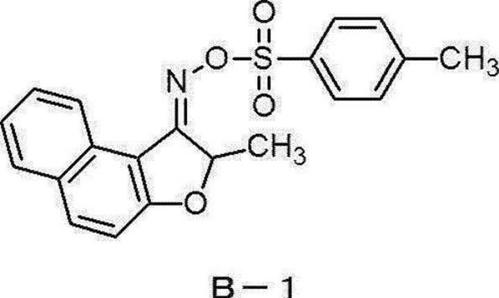
(界面活性剤C-1)
界面活性剤C-1は、下記構造を有する化合物である。
界面活性剤C-1は、下記構造を有する化合物である。

(塩基性化合物D-1)
塩基性化合物D-1は、下記構造を有する化合物である。
塩基性化合物D-1は、下記構造を有する化合物である。

<感光性組成物Bの調製>
以下の成分を混合することによって、感光性組成物Bを調製した。感光性組成物Bは、ネガ型感光性層を形成するための組成物である。
・重合体B-1を含む組成物:固形分換算で21.87質量部
・アロニックスM270(東亞合成株式会社製):0.51質量部
・NKエステルBPE-500(新中村化学工業株式会社製):4.85質量部
・B-CIM(光ラジカル発生剤(光重合開始剤)、Hampford社製、2-(2-クロロフェニル)-4,5-ジフェニルイミダゾール二量体):0.89質量部
・NBCA(増感剤、10-ブチル-2-クロロアクリドン、黒金化成株式会社製):0.05質量部
・N-フェニルカルバモイルメチル-N-カルボキシメチルアニリン(富士フイルム和光純薬株式会社製):0.02質量部
・フェノキサジン(富士フイルム和光純薬株式会社製):0.025質量部
・1-フェニル-3-ピラゾリドン(富士フイルム和光純薬株式会社製):0.001質量部
・LCV(色素、ロイコクリスタルバイオレット、山田化学工業株式会社製):0.053質量部
・VPB-NAPS(色素、ビクトリアピュアブルー-ナフタレンスルホン酸塩、保土谷化学工業株式会社製):0.009質量部
・メチルエチルケトン(三協化学株式会社製):30.87質量部
・プロピレングリコールモノメチルエーテルアセテート:33.92質量部
・テトラヒドロフラン(三菱ケミカル株式会社製):6.93質量部
以下の成分を混合することによって、感光性組成物Bを調製した。感光性組成物Bは、ネガ型感光性層を形成するための組成物である。
・重合体B-1を含む組成物:固形分換算で21.87質量部
・アロニックスM270(東亞合成株式会社製):0.51質量部
・NKエステルBPE-500(新中村化学工業株式会社製):4.85質量部
・B-CIM(光ラジカル発生剤(光重合開始剤)、Hampford社製、2-(2-クロロフェニル)-4,5-ジフェニルイミダゾール二量体):0.89質量部
・NBCA(増感剤、10-ブチル-2-クロロアクリドン、黒金化成株式会社製):0.05質量部
・N-フェニルカルバモイルメチル-N-カルボキシメチルアニリン(富士フイルム和光純薬株式会社製):0.02質量部
・フェノキサジン(富士フイルム和光純薬株式会社製):0.025質量部
・1-フェニル-3-ピラゾリドン(富士フイルム和光純薬株式会社製):0.001質量部
・LCV(色素、ロイコクリスタルバイオレット、山田化学工業株式会社製):0.053質量部
・VPB-NAPS(色素、ビクトリアピュアブルー-ナフタレンスルホン酸塩、保土谷化学工業株式会社製):0.009質量部
・メチルエチルケトン(三協化学株式会社製):30.87質量部
・プロピレングリコールモノメチルエーテルアセテート:33.92質量部
・テトラヒドロフラン(三菱ケミカル株式会社製):6.93質量部
(重合体B-1を含む組成物の調製)
3つ口フラスコにプロピレングリコールモノメチルエーテルアセテート(116.5質量部)を入れ、窒素雰囲気下において90℃に昇温した。スチレン(52.0質量部、富士フイルム和光純薬株式会社製)、メタクリル酸メチル(19.0質量部)、メタクリル酸(29.0質量部、東京化成工業株式会社製)、2,2’-アゾビス(2-メチルプロピオン酸)ジメチル(4.0質量部)、及びプロピレングリコールモノメチルエーテルアセテート(116.5質量部)を含む溶液を、90℃±2℃に維持した3つ口フラスコ溶液中に2時間かけて滴下した。滴下終了後、90℃±2℃で2時間撹拌することで、重合体B-1を含む組成物(固形分濃度:30.0質量%)を得た。
3つ口フラスコにプロピレングリコールモノメチルエーテルアセテート(116.5質量部)を入れ、窒素雰囲気下において90℃に昇温した。スチレン(52.0質量部、富士フイルム和光純薬株式会社製)、メタクリル酸メチル(19.0質量部)、メタクリル酸(29.0質量部、東京化成工業株式会社製)、2,2’-アゾビス(2-メチルプロピオン酸)ジメチル(4.0質量部)、及びプロピレングリコールモノメチルエーテルアセテート(116.5質量部)を含む溶液を、90℃±2℃に維持した3つ口フラスコ溶液中に2時間かけて滴下した。滴下終了後、90℃±2℃で2時間撹拌することで、重合体B-1を含む組成物(固形分濃度:30.0質量%)を得た。
<樹脂組成物C~Eの調製>
以下に示す成分を混合することによって、樹脂組成物C、樹脂組成物D及び樹脂組成物Eを調製した。以下に示す成分の添加量の単位は、質量部である。
以下に示す成分を混合することによって、樹脂組成物C、樹脂組成物D及び樹脂組成物Eを調製した。以下に示す成分の添加量の単位は、質量部である。
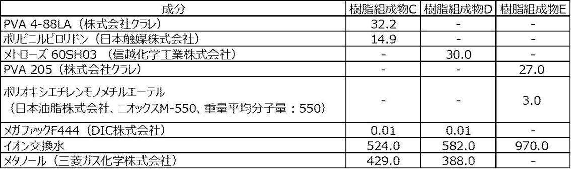
<感光性層及び樹脂層のユニバーサル硬さの測定>
バーコーターを用いて、コスモシャインA4300(50μmの厚さを有するPETフィルム、株式会社東洋紡)の上に感光性組成物を乾燥膜厚が2μmとなるように塗布した。塗布された感光性組成物を、オーブンを用いて100℃で10分間乾燥することで、感光性層を形成した。フィッシャー・インストルメンツ社製HM2000型硬度計に球状圧子(直径:0.4mm)を取り付け、23℃及び50%RH(相対湿度)の環境下で押し込み試験を行った。押し込み試験は、荷重を段階的に増やしながら、最大荷重に到達するまで行った。押し込み試験において、負荷時間を10秒間、クリープ時間を5秒間に設定した。感光性層に接触する球状圧子の表面積及び押し込み深さが試験前の感光性層の厚さの1/10となったときの試験荷重に基づき、感光性層のユニバーサル硬さ(単位:N/mm2)を求めた。押し込み試験を10回繰り返し、感光性層のユニバーサル硬さの算術平均を求めた。感光性組成物を樹脂組成物に変更したこと以外は、感光性層のユニバーサル硬さの測定方法と同じ方法によって、樹脂層のユニバーサル硬さを測定した。測定結果を表3~4に示す。
バーコーターを用いて、コスモシャインA4300(50μmの厚さを有するPETフィルム、株式会社東洋紡)の上に感光性組成物を乾燥膜厚が2μmとなるように塗布した。塗布された感光性組成物を、オーブンを用いて100℃で10分間乾燥することで、感光性層を形成した。フィッシャー・インストルメンツ社製HM2000型硬度計に球状圧子(直径:0.4mm)を取り付け、23℃及び50%RH(相対湿度)の環境下で押し込み試験を行った。押し込み試験は、荷重を段階的に増やしながら、最大荷重に到達するまで行った。押し込み試験において、負荷時間を10秒間、クリープ時間を5秒間に設定した。感光性層に接触する球状圧子の表面積及び押し込み深さが試験前の感光性層の厚さの1/10となったときの試験荷重に基づき、感光性層のユニバーサル硬さ(単位:N/mm2)を求めた。押し込み試験を10回繰り返し、感光性層のユニバーサル硬さの算術平均を求めた。感光性組成物を樹脂組成物に変更したこと以外は、感光性層のユニバーサル硬さの測定方法と同じ方法によって、樹脂層のユニバーサル硬さを測定した。測定結果を表3~4に示す。
<フォトマスク-1の作製>
以下の方法によって、フォトマスク-1を作製した。石英基板(透明支持体、長さ:100mm、幅:100mm、厚さ:2.8mm)の上に、スパッタリングによってクロム薄膜(遮光層、厚さ:170nm)を成膜した。フォトリソグラフィによってクロム薄膜をパターン状に加工し、クロム薄膜のパターン(遮光層)を形成した。フォトリソグラフィでは、具体的に、クロム薄膜の上に配置した感光性層の露光及び現像、クロム薄膜のエッチング、そして樹脂パターンの除去を経て、クロム薄膜のパターンを形成した。フォトマスク-1は、石英基板と、石英基板の上に配置されたクロム薄膜のパターンと、を含む。フォトマスク-1は、線幅が8μmのラインアンドスペースパターン(Duty比=1:1)を有する。
以下の方法によって、フォトマスク-1を作製した。石英基板(透明支持体、長さ:100mm、幅:100mm、厚さ:2.8mm)の上に、スパッタリングによってクロム薄膜(遮光層、厚さ:170nm)を成膜した。フォトリソグラフィによってクロム薄膜をパターン状に加工し、クロム薄膜のパターン(遮光層)を形成した。フォトリソグラフィでは、具体的に、クロム薄膜の上に配置した感光性層の露光及び現像、クロム薄膜のエッチング、そして樹脂パターンの除去を経て、クロム薄膜のパターンを形成した。フォトマスク-1は、石英基板と、石英基板の上に配置されたクロム薄膜のパターンと、を含む。フォトマスク-1は、線幅が8μmのラインアンドスペースパターン(Duty比=1:1)を有する。
<フォトマスク-2の作製>
以下の方法によって、フォトマスク-2を作製した。フォトマスク-1の作製方法に従って作製したフォトマスク-1の石英基板及びクロム薄膜のパターンの上に、下記の保護層形成用組成物-1をスピンコートによって塗布し、2.5μmの厚さを有する保護層を形成した。得られたフォトマスク-2は、石英基板と、石英基板の上に配置されたクロム薄膜のパターンと、石英基板及びクロム薄膜のパターンの上に配置された保護層と、を含む。フォトマスク-2は、線幅が8μmのラインアンドスペースパターン(Duty比=1:1)を有する。
以下の方法によって、フォトマスク-2を作製した。フォトマスク-1の作製方法に従って作製したフォトマスク-1の石英基板及びクロム薄膜のパターンの上に、下記の保護層形成用組成物-1をスピンコートによって塗布し、2.5μmの厚さを有する保護層を形成した。得られたフォトマスク-2は、石英基板と、石英基板の上に配置されたクロム薄膜のパターンと、石英基板及びクロム薄膜のパターンの上に配置された保護層と、を含む。フォトマスク-2は、線幅が8μmのラインアンドスペースパターン(Duty比=1:1)を有する。
(保護層形成用組成物-1)
保護層形成用組成物-1は、以下の成分を含む。
・ブロックポリイソシアネート硬化剤(デュラネートTPA-100、旭化成株式会社):0.74質量部
・アクリルポリオール樹脂(アクリディックA-807、DIC株式会社):3.19質量部
・メチルエチルケトン:3.05質量部
・酢酸エチル:3.05質量部
保護層形成用組成物-1は、以下の成分を含む。
・ブロックポリイソシアネート硬化剤(デュラネートTPA-100、旭化成株式会社):0.74質量部
・アクリルポリオール樹脂(アクリディックA-807、DIC株式会社):3.19質量部
・メチルエチルケトン:3.05質量部
・酢酸エチル:3.05質量部
<フォトマスク-3の作製>
以下の方法によって、フォトマスク-3を作製した。石英製の反応容器中で、フォトマスク-1の作製方法に従って作製したフォトマスク-1の石英基板及びクロム薄膜のパターンを(ヘプタデカフルオロ-1,1,2,2-テトラヒドロデシル)-1-トリエトキシシランの蒸気に、室温で50分間接触させた。フォトマスク-1を100℃で30分間加熱し、保護層を形成した。得られたフォトマスク-3は、石英基板と、石英基板の上に配置されたクロム薄膜のパターンと、石英基板及びクロム薄膜のパターンの上に配置された保護層と、を含む。フォトマスク-3は、線幅が8μmのラインアンドスペースパターン(Duty比=1:1)を有する。
以下の方法によって、フォトマスク-3を作製した。石英製の反応容器中で、フォトマスク-1の作製方法に従って作製したフォトマスク-1の石英基板及びクロム薄膜のパターンを(ヘプタデカフルオロ-1,1,2,2-テトラヒドロデシル)-1-トリエトキシシランの蒸気に、室温で50分間接触させた。フォトマスク-1を100℃で30分間加熱し、保護層を形成した。得られたフォトマスク-3は、石英基板と、石英基板の上に配置されたクロム薄膜のパターンと、石英基板及びクロム薄膜のパターンの上に配置された保護層と、を含む。フォトマスク-3は、線幅が8μmのラインアンドスペースパターン(Duty比=1:1)を有する。
<実施例1~10及び比較例1~6>
表2及び表3の記載に従って、フォトマスクに対してウェットブラスト処理を行うことでフォトマスクの表面粗さを調節した。以下、ウェットブラスト処理の具体的な手順を説明する。研磨剤及び水を含むスラリーを重力方向へ噴射可能な位置に、32cmの幅を有する噴射ノズルを設置した。表2及び表3に示すウェットブラスト処理の条件に従って、圧縮空気によって重力方向へ噴射されるスラリーの中にフォトマスクを通過させることで、クロム薄膜の表面及びクロム薄膜によって覆われていない石英基板の表面(すなわち、透明支持体の第1の面)に対して、ウェットブラスト処理を行った。ウェットブラスト処理におけるフォトマスクの搬送速度は、10mm/秒に設定した。ウェットブラスト処理が施されたフォトマスクを用いて、以下の評価を行った。ただし、表3において「ウェットブラスト処理の条件」の欄に「-」が記載されている実施例及び比較例については、ブラスト処理が施されていないフォトマスクを用いて、以下の評価を行った。
表2及び表3の記載に従って、フォトマスクに対してウェットブラスト処理を行うことでフォトマスクの表面粗さを調節した。以下、ウェットブラスト処理の具体的な手順を説明する。研磨剤及び水を含むスラリーを重力方向へ噴射可能な位置に、32cmの幅を有する噴射ノズルを設置した。表2及び表3に示すウェットブラスト処理の条件に従って、圧縮空気によって重力方向へ噴射されるスラリーの中にフォトマスクを通過させることで、クロム薄膜の表面及びクロム薄膜によって覆われていない石英基板の表面(すなわち、透明支持体の第1の面)に対して、ウェットブラスト処理を行った。ウェットブラスト処理におけるフォトマスクの搬送速度は、10mm/秒に設定した。ウェットブラスト処理が施されたフォトマスクを用いて、以下の評価を行った。ただし、表3において「ウェットブラスト処理の条件」の欄に「-」が記載されている実施例及び比較例については、ブラスト処理が施されていないフォトマスクを用いて、以下の評価を行った。
(接着性の評価)
A4サイズのポリエチレンテレフタレート(PET)フィルム(コスモシャインA4100、厚さ:100μm、株式会社東洋紡)の高平滑面の上に、バーコーターを用いて、表3の記載に従って選択した感光性組成物を乾燥膜厚が3μmとなるように塗布した。塗布された感光性組成物を、オーブンを用いて100℃で10分間乾燥することで、感光性層を形成した。PETフィルム及び感光性層を含む積層体を、23℃及び50%(相対湿度)の条件で1時間保持した後、10cm×10cmのサイズに裁断した。フォトマスクを積層体の感光性層に接触させて、感光性層の上に少なくともクロム薄膜及び石英基板をこの順に配置した。フォトマスク及び積層体に対して、30℃及び80%(相対湿度)の条件で84kgの荷重を21時間付与した。フォトマスクから積層体を剥がす際の感触及びフォトマスクから積層体を剥がした後のフォトマスクの外観に基づき、以下の基準に従って、感光性層に対するフォトマスクの接着性に関する評価を行った。評価結果を表3に示す。
A4サイズのポリエチレンテレフタレート(PET)フィルム(コスモシャインA4100、厚さ:100μm、株式会社東洋紡)の高平滑面の上に、バーコーターを用いて、表3の記載に従って選択した感光性組成物を乾燥膜厚が3μmとなるように塗布した。塗布された感光性組成物を、オーブンを用いて100℃で10分間乾燥することで、感光性層を形成した。PETフィルム及び感光性層を含む積層体を、23℃及び50%(相対湿度)の条件で1時間保持した後、10cm×10cmのサイズに裁断した。フォトマスクを積層体の感光性層に接触させて、感光性層の上に少なくともクロム薄膜及び石英基板をこの順に配置した。フォトマスク及び積層体に対して、30℃及び80%(相対湿度)の条件で84kgの荷重を21時間付与した。フォトマスクから積層体を剥がす際の感触及びフォトマスクから積層体を剥がした後のフォトマスクの外観に基づき、以下の基準に従って、感光性層に対するフォトマスクの接着性に関する評価を行った。評価結果を表3に示す。
-基準-
A:フォトマスクから積層体を剥がす際にフォトマスクに対する積層体の接着感がなく、かつ、フォトマスクに感光性層の接着痕がない。
B:フォトマスクから積層体を剥がす際にフォトマスクに対する積層体の接着感があり、かつ、フォトマスクに感光性層の接着痕がない。
C:フォトマスクから積層体を剥がす際にフォトマスクに対する積層体の接着感があり、かつ、フォトマスクに感光性層の接着痕がある。
D:フォトマスクから積層体を剥がす際にフォトマスクに対する積層体の接着感があり、かつ、感光性層の面積の30%以上がフォトマスクに転写した。
A:フォトマスクから積層体を剥がす際にフォトマスクに対する積層体の接着感がなく、かつ、フォトマスクに感光性層の接着痕がない。
B:フォトマスクから積層体を剥がす際にフォトマスクに対する積層体の接着感があり、かつ、フォトマスクに感光性層の接着痕がない。
C:フォトマスクから積層体を剥がす際にフォトマスクに対する積層体の接着感があり、かつ、フォトマスクに感光性層の接着痕がある。
D:フォトマスクから積層体を剥がす際にフォトマスクに対する積層体の接着感があり、かつ、感光性層の面積の30%以上がフォトマスクに転写した。
(直線性の評価)
A4サイズのPETフィルム(厚さ:100μm)の上に、バーコーターを用いて表3の記載に従って選択した感光性組成物を乾燥膜厚が3μmとなるように塗布した。塗布された感光性組成物を、オーブンを用いて100℃で10分間乾燥することで、感光性層を形成した。線幅が8μmのラインアンドスペースパターン(Duty比 1:1)を有するフォトマスクを感光性層に接触させて、感光性層の上に少なくともクロム薄膜及び石英基板をこの順に配置した。超高圧水銀灯を用いて、フォトマスクを介して感光性層を露光した。感光性層を現像することにより樹脂パターンを形成した。現像は、25℃の1.0%炭酸ナトリウム水溶液を用い、シャワー現像で30秒行った。光学顕微鏡を用いて樹脂パターンを観察し、樹脂パターンにおいて任意に選択した20か所の線幅を測定した。測定値から標準偏差σを求め、標準偏差σを3倍した値をLWR(Line Width Roughness)と定義し、樹脂パターンの直線性の指標とした。LWRの値に基づき、以下の基準に従って、樹脂パターンの直線性に関する評価を行った。評価結果を表3に示す。
A4サイズのPETフィルム(厚さ:100μm)の上に、バーコーターを用いて表3の記載に従って選択した感光性組成物を乾燥膜厚が3μmとなるように塗布した。塗布された感光性組成物を、オーブンを用いて100℃で10分間乾燥することで、感光性層を形成した。線幅が8μmのラインアンドスペースパターン(Duty比 1:1)を有するフォトマスクを感光性層に接触させて、感光性層の上に少なくともクロム薄膜及び石英基板をこの順に配置した。超高圧水銀灯を用いて、フォトマスクを介して感光性層を露光した。感光性層を現像することにより樹脂パターンを形成した。現像は、25℃の1.0%炭酸ナトリウム水溶液を用い、シャワー現像で30秒行った。光学顕微鏡を用いて樹脂パターンを観察し、樹脂パターンにおいて任意に選択した20か所の線幅を測定した。測定値から標準偏差σを求め、標準偏差σを3倍した値をLWR(Line Width Roughness)と定義し、樹脂パターンの直線性の指標とした。LWRの値に基づき、以下の基準に従って、樹脂パターンの直線性に関する評価を行った。評価結果を表3に示す。
-基準-
A:LWR<250nm
B:250nm<LWR≦500nm
C:500nm<LWR
A:LWR<250nm
B:250nm<LWR≦500nm
C:500nm<LWR
<実施例11~18及び比較例7~10>
表2及び表4の記載に従って、フォトマスクに対してウェットブラスト処理を行うことでフォトマスクの表面粗さを調節した。ウェットブラスト処理の具体的な手順は、既述のとおりである。ウェットブラスト処理が施されたフォトマスクを用いて、以下の評価を行った。ただし、表4において「ウェットブラスト処理の条件」の欄に「-」が記載されている実施例及び比較例については、ブラスト処理が施されていないフォトマスクを用いて、以下の評価を行った。
表2及び表4の記載に従って、フォトマスクに対してウェットブラスト処理を行うことでフォトマスクの表面粗さを調節した。ウェットブラスト処理の具体的な手順は、既述のとおりである。ウェットブラスト処理が施されたフォトマスクを用いて、以下の評価を行った。ただし、表4において「ウェットブラスト処理の条件」の欄に「-」が記載されている実施例及び比較例については、ブラスト処理が施されていないフォトマスクを用いて、以下の評価を行った。
(接着性及び直線性の評価)
A4サイズのポリエチレンテレフタレート(PET)フィルム(ルミラー16KS40、東レ株式会社、厚さ:16μm)の上に、バーコーターを用いて、表2及び表4の記載に従って選択した樹脂組成物を乾燥膜厚が表4に記載された値となるように塗布した。塗布された樹脂組成物を、オーブンを用いて100℃で10分間乾燥することで、樹脂層を形成した。樹脂層の上に、バーコーターを用いて感光性組成物Bを乾燥膜厚が3μmとなるように塗布した。塗布された感光性組成物を、オーブンを用いて100℃で10分間乾燥することで、感光性層を形成した。以上の手順によって、PETフィルム(仮支持体)と、樹脂層と、感光性層と、をこの順で含む感光性転写材料を得た。
A4サイズのポリエチレンテレフタレート(PET)フィルム(ルミラー16KS40、東レ株式会社、厚さ:16μm)の上に、バーコーターを用いて、表2及び表4の記載に従って選択した樹脂組成物を乾燥膜厚が表4に記載された値となるように塗布した。塗布された樹脂組成物を、オーブンを用いて100℃で10分間乾燥することで、樹脂層を形成した。樹脂層の上に、バーコーターを用いて感光性組成物Bを乾燥膜厚が3μmとなるように塗布した。塗布された感光性組成物を、オーブンを用いて100℃で10分間乾燥することで、感光性層を形成した。以上の手順によって、PETフィルム(仮支持体)と、樹脂層と、感光性層と、をこの順で含む感光性転写材料を得た。
ポリエチレンテレフタレート(PET)フィルム(厚さ:100μm)上に、スパッタ法にて銅層(厚さ:200nm)を形成することで、銅層付きPET基板を得た。
感光性転写材料を、100℃のロール温度、1.0MPaの線圧、4.0m/分の線速度というラミネート条件で、銅層付きPET基板の上に積み重ねた。得られた積層体は、PTフィルムと、銅層と、感光性層と、樹脂層と、仮支持体と、をこの順で含む。仮支持体であるPETフィルムを剥離した後、実施例1の評価と同じ評価を行った。評価結果を表4に示す。
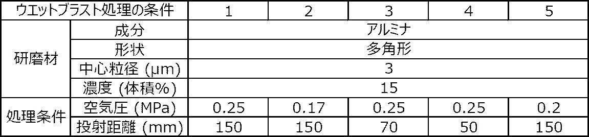


表3~4において、「クロム薄膜の表面粗さ」、「石英基板の表面粗さ」及び「保護層の表面粗さ」は、それぞれ、既述の方法によって測定した。ウェットブラスト処理を施したフォトマスクを用いた実施例及び比較例については、ウェットブラスト処理を施したフォトマスクを用いて表面粗さを測定した。「石英基板の表面粗さ」は、石英基板のクロム薄膜側の表面であって、クロム薄膜で覆われていない部分の表面粗さを示す。つまり、「石英基板の表面粗さ」は、本開示で規定する透明支持体の第1の面の露出部分の表面粗さを示す。
表3~4において、「ヘーズ」は、フォトマスクの光透過部(すなわち、石英基板のクロム薄膜によって覆われていない部分)のヘーズを示す。ヘーズが小さいほど、光の散乱が抑制されていることを示す。ヘーズの測定は、ヘーズ測定装置(商品名:「NDH-5000W」、日本電色工業株式会社製)を用いて、「JIS K 7136」に準拠して行った。ウェットブラスト処理を施したフォトマスクを用いた実施例及び比較例については、ウェットブラスト処理を施したフォトマスクを用いてヘーズを測定した。
比較例1~6に比べて、実施例1~10では感光性層に対するフォトマスクの接着性が低減されており、優れた直線性を有する樹脂パターンが形成されたことがわかった。比較例7~10に比べて、実施例11~18では樹脂層に対するフォトマスクの接着性が低減されており、優れた直線性を有する樹脂パターンが形成されたことがわかった。
2020年8月31日に出願された日本国特許出願2020-145976の開示は、その全体が参照により本明細書に取り込まれる。
本明細書に記載された全ての文献、特許出願、及び技術規格は、個々の文献、特許出願、及び技術規格が参照により取り込まれることが具体的かつ個々に記された場合と同程度に、本明細書中に参照により取り込まれる。
本明細書に記載された全ての文献、特許出願、及び技術規格は、個々の文献、特許出願、及び技術規格が参照により取り込まれることが具体的かつ個々に記された場合と同程度に、本明細書中に参照により取り込まれる。
Claims (19)
- 第1の面及び前記第1の面とは反対側の第2の面を有する透明支持体と、
前記透明支持体の前記第1の面の一部の上に配置された遮光層と、を含み、
前記第1の面の露出部分の表面粗さRzが0.1μm~0.5μmであり、
前記遮光層の表面粗さRzが0.1μm~0.5μmである、
フォトマスク。 - 前記第1の面の露出部分の表面粗さRaが5nm~50nmであり、前記遮光層の表面粗さRaが5nm~50nmである、請求項1に記載のフォトマスク。
- 第1の面及び前記第1の面とは反対側の第2の面を有する透明支持体と、
前記透明支持体の前記第1の面の一部の上に配置された遮光層と、
前記透明支持体の前記第1の面及び前記遮光層の上に配置された保護層と、を含み、
前記保護層の表面粗さRzが0.1μm~0.5μmである、
フォトマスク。 - 前記保護層の表面粗さRaが5nm~50nmである、請求項3に記載のフォトマスク。
- 前記保護層が有機高分子化合物を含む、請求項3又は請求項4に記載のフォトマスク。
- 前記有機高分子化合物がウレタンアクリレートに由来の構成単位を含む、請求項5に記載のフォトマスク。
- 前記保護層がフッ素原子含有化合物を含む、請求項3~請求項6のいずれか1項に記載のフォトマスク。
- 前記透明支持体が平板状の石英ガラスである、請求項1~請求項7のいずれか1項に記載のフォトマスク。
- 前記遮光層がクロムを含む、請求項1~請求項8のいずれか1項に記載のフォトマスク。
- 請求項1~請求項9のいずれか1項に記載のフォトマスクを準備することと、
前記フォトマスクを感光性層に接触させて、前記フォトマスクを介して前記感光性層を露光することと、
を含む露光方法。 - 請求項1~請求項9のいずれか1項に記載のフォトマスクを準備することと、
前記フォトマスクを感光性層に接触させて、前記フォトマスクを介して前記感光性層を露光することと、
露光を経た前記感光性層を現像して、樹脂パターンを形成することと、
を含む樹脂パターンの製造方法。 - 請求項1~請求項9のいずれか1項に記載のフォトマスクを準備することと、
感光性層と、仮支持体と、をこの順で含む積層体を準備することと、
前記フォトマスクを前記仮支持体に接触させて、前記フォトマスク及び前記仮支持体を介して前記感光性層を露光することと、
露光を経た前記感光性層を現像して、樹脂パターンを形成することと、
を含む樹脂パターンの製造方法。 - 請求項1~請求項9のいずれか1項に記載のフォトマスクを準備することと、
感光性層と、仮支持体と、をこの順で含む積層体を準備することと、
前記仮支持体を剥離し、前記感光性層の表面を露出させることと、
前記フォトマスクを前記仮支持体の剥離によって露出した前記感光性層の表面に接触させて、前記フォトマスクを介して前記感光性層を露光することと、
露光を経た前記感光性層を現像して、樹脂パターンを形成することと、
を含む樹脂パターンの製造方法。 - 前記積層体が前記感光性層と前記仮支持体との間に樹脂層を更に含み、押し込み試験において押し込み深さが前記樹脂層の厚さの1/10であるときの試験荷重に基づいて測定される前記樹脂層のユニバーサル硬さが5.0N/mm2以上であり、前記感光性層を露光することにおいて前記フォトマスク及び前記樹脂層を介して前記感光性層を露光する、請求項12又は請求項13に記載の樹脂パターンの製造方法。
- 前記樹脂層がポリビニルアルコールを含む、請求項14に記載の樹脂パターンの製造方法。
- 押し込み試験において押し込み深さが前記感光性層の厚さの1/10であるときの試験荷重に基づいて測定される前記感光性層のユニバーサル硬さが5.0N/mm2以上である、請求項11~請求項15のいずれか1項に記載の樹脂パターンの製造方法。
- 第1の面及び前記第1の面とは反対側の第2の面を有する透明支持体と、前記透明支持体の前記第1の面の一部の上に配置された遮光層と、を含む積層体を準備することと、
前記積層体に対してブラスト処理を施すことで、前記第1の面の露出部分の表面粗さRzを0.1μm~0.5μmに調節し、かつ、前記遮光層の表面粗さRzを0.1μm~0.5μmに調節することと、
を含むフォトマスクの製造方法。 - 第1の面及び前記第1の面とは反対側の第2の面を有する透明支持体と、前記透明支持体の前記第1の面の一部の上に配置された遮光層と、前記透明支持体の前記第1の面及び前記遮光層の上に配置された保護層と、を含む積層体を準備することと、
前記積層体に対してブラスト処理を施すことで、前記保護層の表面粗さRzを0.1μm~0.5μmに調節することと、
を含むフォトマスクの製造方法。 - 前記ブラスト処理がウェットブラスト処理である、請求項17又は請求項18に記載のフォトマスクの製造方法。
Priority Applications (2)
| Application Number | Priority Date | Filing Date | Title |
|---|---|---|---|
| CN202180055266.4A CN116194845A (zh) | 2020-08-31 | 2021-07-07 | 光掩模、曝光方法、树脂图案的制造方法及光掩模的制造方法 |
| JP2022545503A JPWO2022044557A1 (ja) | 2020-08-31 | 2021-07-07 |
Applications Claiming Priority (2)
| Application Number | Priority Date | Filing Date | Title |
|---|---|---|---|
| JP2020-145976 | 2020-08-31 | ||
| JP2020145976 | 2020-08-31 |
Publications (1)
| Publication Number | Publication Date |
|---|---|
| WO2022044557A1 true WO2022044557A1 (ja) | 2022-03-03 |
Family
ID=80353208
Family Applications (1)
| Application Number | Title | Priority Date | Filing Date |
|---|---|---|---|
| PCT/JP2021/025672 Ceased WO2022044557A1 (ja) | 2020-08-31 | 2021-07-07 | フォトマスク、露光方法、樹脂パターンの製造方法及びフォトマスクの製造方法 |
Country Status (4)
| Country | Link |
|---|---|
| JP (1) | JPWO2022044557A1 (ja) |
| CN (1) | CN116194845A (ja) |
| TW (1) | TW202225823A (ja) |
| WO (1) | WO2022044557A1 (ja) |
Citations (11)
| Publication number | Priority date | Publication date | Assignee | Title |
|---|---|---|---|---|
| JPS5854869B2 (ja) * | 1980-12-08 | 1983-12-07 | 富士通株式会社 | 樹脂被膜の形成方法 |
| JPS62235953A (ja) * | 1986-04-07 | 1987-10-16 | Fuotopori Ouka Kk | ホトマスク |
| JPH02235063A (ja) * | 1989-03-08 | 1990-09-18 | Ricoh Co Ltd | 密着露光用マスク |
| JPH09211842A (ja) * | 1996-02-08 | 1997-08-15 | Washi Kosan Kk | 光学的手段を用いた電子回路形成における光反射防止方法及びその装置とその製品 |
| JP2000258894A (ja) * | 1999-03-11 | 2000-09-22 | Kimoto & Co Ltd | 表面保護フィルム |
| JP2005128412A (ja) * | 2003-10-27 | 2005-05-19 | Mitsubishi Chemicals Corp | 画像形成材及びそれを用いた画像形成方法 |
| WO2007074778A1 (ja) * | 2005-12-26 | 2007-07-05 | Kimoto Co., Ltd. | 表面保護フィルム |
| JP2007199434A (ja) * | 2006-01-27 | 2007-08-09 | Dainippon Printing Co Ltd | プロキシミティ方式の露光方法とそれに用いられるマスク基板、および該マスク基板の作製方法 |
| JP2008292655A (ja) * | 2007-05-23 | 2008-12-04 | Sekisui Chem Co Ltd | フォトマスク保護用粘着テープ |
| JP2010237542A (ja) * | 2009-03-31 | 2010-10-21 | Lintec Corp | マスクフィルム用部材、それを用いたマスクフィルムの製造方法及び感光性樹脂印刷版の製造方法 |
| JP2014010333A (ja) * | 2012-06-29 | 2014-01-20 | Asahi Kasei E-Materials Corp | 感光性樹脂組成物及び感光性樹脂積層体 |
Family Cites Families (3)
| Publication number | Priority date | Publication date | Assignee | Title |
|---|---|---|---|---|
| JP2006018190A (ja) * | 2004-07-05 | 2006-01-19 | Matsushita Electric Ind Co Ltd | フォトマスクとレジストパターン形成方法及びマスター情報担体の製造方法 |
| TW201922815A (zh) * | 2017-10-13 | 2019-06-16 | 日商富士軟片股份有限公司 | 電路配線的製造方法、觸控面板的製造方法及附圖案基材的製造方法 |
| JP7011046B2 (ja) * | 2018-03-29 | 2022-01-26 | 富士フイルム株式会社 | 感光性転写材料、レジストパターンの製造方法、回路配線の製造方法、タッチパネル、及び、タッチパネル表示装置 |
-
2021
- 2021-07-07 WO PCT/JP2021/025672 patent/WO2022044557A1/ja not_active Ceased
- 2021-07-07 CN CN202180055266.4A patent/CN116194845A/zh active Pending
- 2021-07-07 JP JP2022545503A patent/JPWO2022044557A1/ja not_active Abandoned
- 2021-07-14 TW TW110125916A patent/TW202225823A/zh unknown
Patent Citations (11)
| Publication number | Priority date | Publication date | Assignee | Title |
|---|---|---|---|---|
| JPS5854869B2 (ja) * | 1980-12-08 | 1983-12-07 | 富士通株式会社 | 樹脂被膜の形成方法 |
| JPS62235953A (ja) * | 1986-04-07 | 1987-10-16 | Fuotopori Ouka Kk | ホトマスク |
| JPH02235063A (ja) * | 1989-03-08 | 1990-09-18 | Ricoh Co Ltd | 密着露光用マスク |
| JPH09211842A (ja) * | 1996-02-08 | 1997-08-15 | Washi Kosan Kk | 光学的手段を用いた電子回路形成における光反射防止方法及びその装置とその製品 |
| JP2000258894A (ja) * | 1999-03-11 | 2000-09-22 | Kimoto & Co Ltd | 表面保護フィルム |
| JP2005128412A (ja) * | 2003-10-27 | 2005-05-19 | Mitsubishi Chemicals Corp | 画像形成材及びそれを用いた画像形成方法 |
| WO2007074778A1 (ja) * | 2005-12-26 | 2007-07-05 | Kimoto Co., Ltd. | 表面保護フィルム |
| JP2007199434A (ja) * | 2006-01-27 | 2007-08-09 | Dainippon Printing Co Ltd | プロキシミティ方式の露光方法とそれに用いられるマスク基板、および該マスク基板の作製方法 |
| JP2008292655A (ja) * | 2007-05-23 | 2008-12-04 | Sekisui Chem Co Ltd | フォトマスク保護用粘着テープ |
| JP2010237542A (ja) * | 2009-03-31 | 2010-10-21 | Lintec Corp | マスクフィルム用部材、それを用いたマスクフィルムの製造方法及び感光性樹脂印刷版の製造方法 |
| JP2014010333A (ja) * | 2012-06-29 | 2014-01-20 | Asahi Kasei E-Materials Corp | 感光性樹脂組成物及び感光性樹脂積層体 |
Also Published As
| Publication number | Publication date |
|---|---|
| CN116194845A (zh) | 2023-05-30 |
| JPWO2022044557A1 (ja) | 2022-03-03 |
| TW202225823A (zh) | 2022-07-01 |
Similar Documents
| Publication | Publication Date | Title |
|---|---|---|
| JP7607646B2 (ja) | 構造体の製造方法、及び、構造体 | |
| CN115768838B (zh) | 组合物、转印膜、层叠体的制造方法、电路配线的制造方法及电子器件的制造方法 | |
| JP7743301B2 (ja) | 蒸着マスク製造用感光性転写材料、及び、蒸着マスクの製造方法 | |
| WO2022044557A1 (ja) | フォトマスク、露光方法、樹脂パターンの製造方法及びフォトマスクの製造方法 | |
| TW202234179A (zh) | 導電圖案的製造方法及電子元件的製造方法 | |
| JP2023076385A (ja) | 樹脂パターンの製造方法、導電性パターンの製造方法及び積層体 | |
| CN115685684A (zh) | 感光性组合物、感光性组合物层、转印膜、具有导体图案的层叠体的制造方法 | |
| JP7844123B2 (ja) | 感光性組成物、転写フィルム及び導体パターンを有する積層体の製造方法 | |
| JP7848140B2 (ja) | 積層体の製造方法、回路配線の製造方法、転写フィルム | |
| CN114901442A (zh) | 切割物的制造方法及层叠体 | |
| WO2021176811A1 (ja) | 感光性転写材料、及び回路配線の製造方法 | |
| CN116235111B (zh) | 感光性转印材料、树脂图案的制造方法、电路配线的制造方法及触摸面板的制造方法 | |
| JP7771090B2 (ja) | 感光性転写材料、樹脂パターンの製造方法、積層体の製造方法、回路配線の製造方法、及び、電子デバイスの製造方法 | |
| JP7759347B2 (ja) | 積層体の製造方法、回路配線の製造方法、転写フィルム | |
| JP7771091B2 (ja) | 感光性転写材料、樹脂パターンの製造方法、積層体の製造方法、回路配線の製造方法、及び、電子デバイスの製造方法 | |
| CN115485621B (zh) | 感光性转印材料、树脂图案的制造方法、电路配线的制造方法及触摸面板的制造方法 | |
| JP7455955B2 (ja) | 感光性転写材料、及び回路配線の製造方法 | |
| CN114930250B (zh) | 树脂图案的制造方法、电路配线的制造方法、触摸面板的制造方法及感光性转印部件 | |
| CN118475879A (zh) | 抗蚀剂图案的制造方法、层叠体的制造方法及直接成像曝光用感光性转印材料 | |
| CN116356321A (zh) | 蒸镀掩模的制造方法 | |
| WO2024024864A1 (ja) | 感光性転写材料及びその製造方法、樹脂パターンの製造方法、並びに、回路配線の製造方法 | |
| JP2024018718A (ja) | 積層体及び積層体の製造方法 | |
| JP2024052221A (ja) | 積層体及び積層体の製造方法 | |
| CN117621587A (zh) | 层叠体及层叠体的制造方法 | |
| WO2022138246A1 (ja) | 転写材料及び積層体の製造方法 |
Legal Events
| Date | Code | Title | Description |
|---|---|---|---|
| 121 | Ep: the epo has been informed by wipo that ep was designated in this application |
Ref document number: 21860987 Country of ref document: EP Kind code of ref document: A1 |
|
| ENP | Entry into the national phase |
Ref document number: 2022545503 Country of ref document: JP Kind code of ref document: A |
|
| NENP | Non-entry into the national phase |
Ref country code: DE |
|
| 122 | Ep: pct application non-entry in european phase |
Ref document number: 21860987 Country of ref document: EP Kind code of ref document: A1 |