WO2022038741A1 - 運転支援装置および運転支援方法 - Google Patents
運転支援装置および運転支援方法 Download PDFInfo
- Publication number
- WO2022038741A1 WO2022038741A1 PCT/JP2020/031441 JP2020031441W WO2022038741A1 WO 2022038741 A1 WO2022038741 A1 WO 2022038741A1 JP 2020031441 W JP2020031441 W JP 2020031441W WO 2022038741 A1 WO2022038741 A1 WO 2022038741A1
- Authority
- WO
- WIPO (PCT)
- Prior art keywords
- vehicle
- driving
- control unit
- support
- driver
- Prior art date
- Legal status (The legal status is an assumption and is not a legal conclusion. Google has not performed a legal analysis and makes no representation as to the accuracy of the status listed.)
- Ceased
Links
Images


Classifications
-
- B—PERFORMING OPERATIONS; TRANSPORTING
- B60—VEHICLES IN GENERAL
- B60W—CONJOINT CONTROL OF VEHICLE SUB-UNITS OF DIFFERENT TYPE OR DIFFERENT FUNCTION; CONTROL SYSTEMS SPECIALLY ADAPTED FOR HYBRID VEHICLES; ROAD VEHICLE DRIVE CONTROL SYSTEMS FOR PURPOSES NOT RELATED TO THE CONTROL OF A PARTICULAR SUB-UNIT
- B60W40/00—Estimation or calculation of non-directly measurable driving parameters for road vehicle drive control systems not related to the control of a particular sub unit, e.g. by using mathematical models
- B60W40/08—Estimation or calculation of non-directly measurable driving parameters for road vehicle drive control systems not related to the control of a particular sub unit, e.g. by using mathematical models related to drivers or passengers
- B60W40/09—Driving style or behaviour
-
- B—PERFORMING OPERATIONS; TRANSPORTING
- B60—VEHICLES IN GENERAL
- B60W—CONJOINT CONTROL OF VEHICLE SUB-UNITS OF DIFFERENT TYPE OR DIFFERENT FUNCTION; CONTROL SYSTEMS SPECIALLY ADAPTED FOR HYBRID VEHICLES; ROAD VEHICLE DRIVE CONTROL SYSTEMS FOR PURPOSES NOT RELATED TO THE CONTROL OF A PARTICULAR SUB-UNIT
- B60W50/00—Details of control systems for road vehicle drive control not related to the control of a particular sub-unit, e.g. process diagnostic or vehicle driver interfaces
- B60W50/08—Interaction between the driver and the control system
-
- B—PERFORMING OPERATIONS; TRANSPORTING
- B60—VEHICLES IN GENERAL
- B60W—CONJOINT CONTROL OF VEHICLE SUB-UNITS OF DIFFERENT TYPE OR DIFFERENT FUNCTION; CONTROL SYSTEMS SPECIALLY ADAPTED FOR HYBRID VEHICLES; ROAD VEHICLE DRIVE CONTROL SYSTEMS FOR PURPOSES NOT RELATED TO THE CONTROL OF A PARTICULAR SUB-UNIT
- B60W30/00—Purposes of road vehicle drive control systems not related to the control of a particular sub-unit, e.g. of systems using conjoint control of vehicle sub-units
- B60W30/08—Active safety systems predicting or avoiding probable or impending collision or attempting to minimise its consequences
- B60W30/09—Taking automatic action to avoid collision, e.g. braking and steering
-
- B—PERFORMING OPERATIONS; TRANSPORTING
- B60—VEHICLES IN GENERAL
- B60W—CONJOINT CONTROL OF VEHICLE SUB-UNITS OF DIFFERENT TYPE OR DIFFERENT FUNCTION; CONTROL SYSTEMS SPECIALLY ADAPTED FOR HYBRID VEHICLES; ROAD VEHICLE DRIVE CONTROL SYSTEMS FOR PURPOSES NOT RELATED TO THE CONTROL OF A PARTICULAR SUB-UNIT
- B60W30/00—Purposes of road vehicle drive control systems not related to the control of a particular sub-unit, e.g. of systems using conjoint control of vehicle sub-units
- B60W30/18—Propelling the vehicle
- B60W30/18009—Propelling the vehicle related to particular drive situations
- B60W30/18163—Lane change; Overtaking manoeuvres
-
- B—PERFORMING OPERATIONS; TRANSPORTING
- B60—VEHICLES IN GENERAL
- B60W—CONJOINT CONTROL OF VEHICLE SUB-UNITS OF DIFFERENT TYPE OR DIFFERENT FUNCTION; CONTROL SYSTEMS SPECIALLY ADAPTED FOR HYBRID VEHICLES; ROAD VEHICLE DRIVE CONTROL SYSTEMS FOR PURPOSES NOT RELATED TO THE CONTROL OF A PARTICULAR SUB-UNIT
- B60W40/00—Estimation or calculation of non-directly measurable driving parameters for road vehicle drive control systems not related to the control of a particular sub unit, e.g. by using mathematical models
- B60W40/02—Estimation or calculation of non-directly measurable driving parameters for road vehicle drive control systems not related to the control of a particular sub unit, e.g. by using mathematical models related to ambient conditions
- B60W40/04—Traffic conditions
-
- B—PERFORMING OPERATIONS; TRANSPORTING
- B60—VEHICLES IN GENERAL
- B60W—CONJOINT CONTROL OF VEHICLE SUB-UNITS OF DIFFERENT TYPE OR DIFFERENT FUNCTION; CONTROL SYSTEMS SPECIALLY ADAPTED FOR HYBRID VEHICLES; ROAD VEHICLE DRIVE CONTROL SYSTEMS FOR PURPOSES NOT RELATED TO THE CONTROL OF A PARTICULAR SUB-UNIT
- B60W50/00—Details of control systems for road vehicle drive control not related to the control of a particular sub-unit, e.g. process diagnostic or vehicle driver interfaces
- B60W50/08—Interaction between the driver and the control system
- B60W50/14—Means for informing the driver, warning the driver or prompting a driver intervention
-
- B—PERFORMING OPERATIONS; TRANSPORTING
- B60—VEHICLES IN GENERAL
- B60W—CONJOINT CONTROL OF VEHICLE SUB-UNITS OF DIFFERENT TYPE OR DIFFERENT FUNCTION; CONTROL SYSTEMS SPECIALLY ADAPTED FOR HYBRID VEHICLES; ROAD VEHICLE DRIVE CONTROL SYSTEMS FOR PURPOSES NOT RELATED TO THE CONTROL OF A PARTICULAR SUB-UNIT
- B60W60/00—Drive control systems specially adapted for autonomous road vehicles
- B60W60/005—Handover processes
- B60W60/0051—Handover processes from occupants to vehicle
-
- B—PERFORMING OPERATIONS; TRANSPORTING
- B60—VEHICLES IN GENERAL
- B60W—CONJOINT CONTROL OF VEHICLE SUB-UNITS OF DIFFERENT TYPE OR DIFFERENT FUNCTION; CONTROL SYSTEMS SPECIALLY ADAPTED FOR HYBRID VEHICLES; ROAD VEHICLE DRIVE CONTROL SYSTEMS FOR PURPOSES NOT RELATED TO THE CONTROL OF A PARTICULAR SUB-UNIT
- B60W50/00—Details of control systems for road vehicle drive control not related to the control of a particular sub-unit, e.g. process diagnostic or vehicle driver interfaces
- B60W50/08—Interaction between the driver and the control system
- B60W50/14—Means for informing the driver, warning the driver or prompting a driver intervention
- B60W2050/143—Alarm means
-
- B—PERFORMING OPERATIONS; TRANSPORTING
- B60—VEHICLES IN GENERAL
- B60W—CONJOINT CONTROL OF VEHICLE SUB-UNITS OF DIFFERENT TYPE OR DIFFERENT FUNCTION; CONTROL SYSTEMS SPECIALLY ADAPTED FOR HYBRID VEHICLES; ROAD VEHICLE DRIVE CONTROL SYSTEMS FOR PURPOSES NOT RELATED TO THE CONTROL OF A PARTICULAR SUB-UNIT
- B60W50/00—Details of control systems for road vehicle drive control not related to the control of a particular sub-unit, e.g. process diagnostic or vehicle driver interfaces
- B60W50/08—Interaction between the driver and the control system
- B60W50/14—Means for informing the driver, warning the driver or prompting a driver intervention
- B60W2050/146—Display means
-
- B—PERFORMING OPERATIONS; TRANSPORTING
- B60—VEHICLES IN GENERAL
- B60W—CONJOINT CONTROL OF VEHICLE SUB-UNITS OF DIFFERENT TYPE OR DIFFERENT FUNCTION; CONTROL SYSTEMS SPECIALLY ADAPTED FOR HYBRID VEHICLES; ROAD VEHICLE DRIVE CONTROL SYSTEMS FOR PURPOSES NOT RELATED TO THE CONTROL OF A PARTICULAR SUB-UNIT
- B60W2540/00—Input parameters relating to occupants
- B60W2540/30—Driving style
-
- B—PERFORMING OPERATIONS; TRANSPORTING
- B60—VEHICLES IN GENERAL
- B60W—CONJOINT CONTROL OF VEHICLE SUB-UNITS OF DIFFERENT TYPE OR DIFFERENT FUNCTION; CONTROL SYSTEMS SPECIALLY ADAPTED FOR HYBRID VEHICLES; ROAD VEHICLE DRIVE CONTROL SYSTEMS FOR PURPOSES NOT RELATED TO THE CONTROL OF A PARTICULAR SUB-UNIT
- B60W2554/00—Input parameters relating to objects
- B60W2554/80—Spatial relation or speed relative to objects
Definitions
- This disclosure relates to a driving support device and a driving support method that provide appropriate driving support to a driver who has performed dangerous driving.
- Patent Document 1 the distance information between the own vehicle and another vehicle traveling in front of the own vehicle (first information), the left and right lines for dividing the traveling lane of the own vehicle, and the left-right direction of the own vehicle.
- Information indicating the relative positional relationship of the vehicle (second information) is acquired, the distance between vehicles is determined to be short based on the first information, and an abnormality (unusual) is determined based on the second information and statistical values.
- an abnormality is determined based on the second information and statistical values.
- dangerous driving includes driving that the driver of the own vehicle intentionally performs with respect to other vehicles, and driving that is not intended by the driver of the own vehicle but irritates the driver of the other vehicle. Will be. For example, if a warning sound is emitted to a driver who is driving in a hurry, the driver may be stroked backwards, and more dangerous driving may be performed. On the other hand, if a warning sound is emitted to a driver who is driving in an irritated manner, the driver may notice his / her driving situation and change his / her driving. Therefore, it is considered effective to provide driving support to the driver of the own vehicle according to each of the agitated driving and the irritated driving.
- Patent Document 1 since the notification is made uniformly without distinguishing between the fanning operation and the irritating operation, the above problem may occur. Therefore, in Patent Document 1, it cannot be said that appropriate driving support is provided to a driver who has performed a fanning operation or an irritated operation.
- the present disclosure has been made to solve such a problem, and is a driving support device and a driving support method capable of providing appropriate driving support to a driver who has been driving in a hurry or in an irritated manner.
- the purpose is to provide.
- the driving support device includes driving that the driver of the own vehicle intentionally performs with respect to another vehicle, and driving of another vehicle that is not the intention of the driver of the own vehicle.
- Driving of own vehicle according to the driving situation judgment unit that judges the driving situation including the frustrating driving that irritates the person, and the case where the driving situation judgment unit judges that the driving is a fanning operation and the case where the driving situation is judged to be annoying driving. It is equipped with a support control unit that controls to support the driving of a person.
- the driving support device controls to support the driving of the driver of the own vehicle according to the case where the driving situation judgment unit determines that the driving is agitated and the case where the driving is determined to be annoying. It is possible to provide appropriate driving support to a driver who has been agitated or irritated.
- FIG. It is a block diagram which shows an example of the structure of the driving support device by Embodiment 1.
- FIG. It is a block diagram which shows an example of the structure of the driving support device by Embodiment 1.
- FIG. It is a figure which shows an example of the driving support by Embodiment 1.
- FIG. It is a figure which shows an example of the driving support by Embodiment 1.
- FIG. It is a figure which shows an example of the driving support by Embodiment 1.
- FIG. It is a figure which shows an example of the driving support by Embodiment 1.
- FIG. It is a figure which shows an example of the driving support by Embodiment 1.
- FIG. It is a flowchart which shows an example of the operation of the driving support apparatus by Embodiment 1.
- FIG. It is a block diagram which shows an example of the structure of the driving support device by the modification of Embodiment 1.
- FIG. It is a block diagram which shows an example of the structure of the driving support device by Embodiment 2.
- Embodiment 2 It is a figure which shows an example of the driving support by Embodiment 2.
- FIG. It is a figure which shows an example of the driving support by Embodiment 2.
- FIG. It is a figure which shows an example of the driving support by Embodiment 2.
- FIG. It is a figure which shows an example of the driving support by Embodiment 2.
- FIG. It is a figure which shows an example of the driving support by Embodiment 2.
- FIG. It is a flowchart which shows an example of the operation of the driving support apparatus by Embodiment 2.
- FIG. 1 It is a block diagram which shows an example of the structure of the driving support device by the modification of Embodiment 2. It is a block diagram which shows an example of the structure of the driving support device by Embodiment 3.
- FIG. It is a figure which shows an example of the driving support by Embodiment 3.
- FIG. It is a flowchart which shows an example of the operation of the driving support apparatus by Embodiment 3.
- FIG. It is a block diagram which shows an example of the structure of the driving support device by the modification of Embodiment 3.
- FIG. 4 It is a figure which shows an example of the driving support by Embodiment 4.
- FIG. It is a flowchart which shows an example of the operation of the driving support apparatus by Embodiment 4.
- FIG. It is a block diagram which shows an example of the structure of the driving support apparatus according to Embodiment 5. It is a block diagram which shows an example of the hardware composition of the driving support apparatus according to Embodiments 1-5. It is a block diagram which shows an example of the hardware composition of the driving support apparatus according to Embodiments 1-5. It is a block diagram which shows an example of the structure of the driving support system by Embodiment 1-5.
- FIG. 1 is a block diagram showing an example of the configuration of the driving support device 1 according to the first embodiment. Note that FIG. 1 shows the minimum necessary configuration for configuring the driving support device according to the first embodiment. It is assumed that the driving support device 1 is mounted in a vehicle (hereinafter referred to as "own vehicle").
- the driving support device 1 includes a driving status determination unit 2 and a support control unit 3.
- the driving situation determination unit 2 includes a driving operation intentionally performed by the driver of the own vehicle with respect to another vehicle and an irritating driving that is not intended by the driver of the own vehicle but irritates the driver of the other vehicle. Judge the driving situation.
- the support control unit 3 controls to support the driving of the driver of the own vehicle according to each of the case where the driving situation determination unit 2 determines that the driving is agitated and the case where the driving is determined to be annoying.
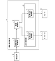
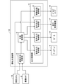
- FIG. 2 is a block diagram showing an example of the configuration of the driving support device 4 according to another configuration.
- the driving support device 4 includes a driving status determination unit 2, a support control unit 3, and an output control unit 5.
- the output control unit 5 includes a display output control unit 6 and an audio output control unit 7. Further, the driving condition determination unit 2 is connected to the vehicle sensor 8, the display output control unit 6 is connected to the display 9, and the audio output control unit 7 is connected to the speaker 10.
- the vehicle sensor 8 detects the situation around the own vehicle including the relative position of the other vehicle with respect to the own vehicle and the own vehicle and the lane in which the other vehicle is traveling. Further, the vehicle sensor 8 may obtain the relative speed of the other vehicle based on the time-series change of the relative position of the other vehicle.
- the vehicle sensor 8 may be, for example, a camera.
- the vehicle sensor 8 is a camera, it is possible to detect the relative position of the other vehicle with respect to the own vehicle and the lane in which the own vehicle and the other vehicle are traveling by performing image processing on the image taken around the own vehicle. can.
- the driving status determination unit 2 determines the driving status including the agitated driving and the irritated driving based on the information acquired from the vehicle sensor 8. Specifically, the driving situation determination unit 2 states that when the own vehicle has executed a specific action for the same other vehicle more than a predetermined number of times, the driver of the own vehicle is driving in a hurry. to decide. Further, the driving situation determination unit 2 determines that the driver of the own vehicle is irritating and driving when the own vehicle temporarily executes a specific action with respect to the same other vehicle.
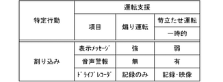
- Examples of the specific action referred to by the driving situation determination unit 2 when determining the driving in a hurry and the irritated driving include each specific action shown in FIGS. 3 to 7. That is, as specific actions, for example, “driving to occupy the overtaking lane", “tailgating", “interruption”, “approaching the vehicle in front”, “driving to the vehicle in front”, “driving to the vehicle in the rear” “Sudden braking” and “staggering driving to the vehicle behind” can be mentioned.
- each specific action shown in FIGS. 3 to 7 is an example, and other driving may be a specific action. For example, driving in a situation where the own vehicle and another vehicle are on a road that cannot be overtaken and the own vehicle is in front of the other vehicle may be a specific action.
- the driving situation determination unit 2 determines whether or not both the own vehicle and the other vehicle are in the overtaking lane based on the information of the lane in which the own vehicle and the other vehicle are traveling acquired from the vehicle sensor 8. to decide. Further, the driving situation determination unit 2 determines whether or not the own vehicle exists in front of the other vehicle based on the information on the relative position of the other vehicle with respect to the own vehicle acquired from the vehicle sensor 8.
- the driving situation determination unit 2 determines that the driver of the own vehicle is performing "driving that occupies the overtaking lane", what kind of "driving that occupies the overtaking lane" is performed. Based on this, determine whether you are driving in a hurry or in an irritated state. Specifically, the driving situation determination unit 2 determines that the driver of the own vehicle is performing the driving while repeatedly executing the "driving that occupies the overtaking lane" more than a predetermined number of times. do. Further, the driving situation determination unit 2 determines that the driver of the own vehicle is performing annoying driving when the driver of the own vehicle is temporarily performing "driving that occupies the overtaking lane".
- the "width-alignment" shown in FIG. 4 is to perform a width-alignment operation with respect to another vehicle in which the own vehicle is traveling in the adjacent lane. Specifically, in a situation where the own vehicle and another vehicle are in lanes adjacent to each other and the own vehicle and the other vehicle are running in parallel, the driver of the own vehicle brings the own vehicle closer to the other vehicle. Is to do. Such traveling of the own vehicle is traveling in which the own vehicle approaches another vehicle to a predetermined distance or less, and the other vehicle causes an avoidance action with respect to the own vehicle.
- the driving situation determination unit 2 determines whether or not the own vehicle and the other vehicle are in lanes adjacent to each other based on the information of the lane in which the own vehicle and the other vehicle are traveling acquired from the vehicle sensor 8. to decide. Further, the driving situation determination unit 2 determines whether or not the own vehicle and the other vehicle are running in parallel based on the information on the relative position of the other vehicle with respect to the own vehicle acquired from the vehicle sensor 8.
- the driving situation determination unit 2 performs a fanning operation or an irritated operation based on what kind of "width adjustment” is performed. Determine which one you are doing. Specifically, the driving situation determination unit 2 determines that the driver of the own vehicle is performing the driving when the driver of the own vehicle repeatedly executes the "width adjustment" more than a predetermined number of times. In addition, the driving situation determination unit 2 determines that the driver of the own vehicle is irritating and driving when the driver of the own vehicle is temporarily performing "tailgating".
- the "interruption" shown in FIG. 5 is to perform an operation in which the own vehicle suddenly invades in front of another vehicle and interrupts. Specifically, in a situation where the own vehicle and another vehicle are traveling in different lanes, the driver of the own vehicle suddenly interrupts the own vehicle in front of the other vehicle. Such traveling of the own vehicle is traveling in which the own vehicle approaches the other vehicle to a predetermined distance or less, and the other vehicle causes the other vehicle to take an evasive action against the own vehicle. In this case, the driving situation determination unit 2 determines whether or not the own vehicle and the other vehicle are in different lanes based on the information of the lane in which the own vehicle and the other vehicle are traveling acquired from the vehicle sensor 8. .. Further, the driving situation determination unit 2 determines whether or not the own vehicle suddenly cuts in front of the other vehicle based on the information on the relative position of the other vehicle with respect to the own vehicle acquired from the vehicle sensor 8.
- the driving situation determination unit 2 determines that the driver of the own vehicle is performing the "interruption"
- either the driving or the frustrating driving is performed based on what kind of "interruption” is being performed. Determine if you are doing it.
- the driving situation determination unit 2 determines that the driver of the own vehicle is performing the driving when the driver of the own vehicle repeatedly executes the "interruption" more than a predetermined number of times. Further, the driving situation determination unit 2 determines that the driver of the own vehicle is performing annoying driving when the "interruption" is temporarily executed.
- the “approach to the vehicle in front” shown in FIG. 6 means that the own vehicle approaches another vehicle in the same lane within a predetermined distance. Further, “staggering driving to a vehicle in front” is driving in which the own vehicle approaches another vehicle in the same lane while staggering within a predetermined distance. Such traveling of the own vehicle is traveling in which the own vehicle approaches the other vehicle to a predetermined distance or less, and the other vehicle causes the other vehicle to take an evasive action against the own vehicle. In this case, the driving situation determination unit 2 determines whether or not the own vehicle and the other vehicle are in the same lane based on the information of the lane in which the own vehicle and the other vehicle are traveling acquired from the vehicle sensor 8. .. Further, the driving situation determination unit 2 determines whether or not the own vehicle has approached the preceding other vehicle within a predetermined distance based on the information on the relative position of the other vehicle with respect to the own vehicle acquired from the vehicle sensor 8. To judge.
- the driving situation determination unit 2 determines that the driver of the own vehicle is "approaching the vehicle in front” or “driving staggering to the vehicle in front”, what kind of “approach to the vehicle in front” or Based on whether the vehicle is “staggering to the vehicle in front”, it is determined whether the driver is driving in a hurry or in an irritated state. Specifically, the driving situation determination unit 2 is agitated when the driver of the own vehicle repeatedly executes "approaching the vehicle in front” or “driving to the vehicle in front” more than a predetermined number of times. Judge that you are driving. In addition, the driving situation determination unit 2 determines that the driver of the own vehicle is performing annoying driving when the driver of the own vehicle is temporarily executing "approaching the vehicle in front” or “driving to the vehicle in front”. do.
- “Sudden braking to the rear vehicle” shown in FIG. 7 means that the own vehicle and the other vehicle are driving in the same lane and the own vehicle suddenly brakes in front of the other vehicle.
- “staggering driving to the rear vehicle” is driving in which the own vehicle approaches the other vehicle behind while staggering within a predetermined distance in a situation where the own vehicle and another vehicle are traveling in the same lane. Is to do.
- Such traveling of the own vehicle is traveling in which the own vehicle approaches the other vehicle to a predetermined distance or less, and the other vehicle causes the other vehicle to take an evasive action against the own vehicle.
- the driving situation determination unit 2 determines whether or not the own vehicle and the other vehicle are in the same lane based on the information of the lane in which the own vehicle and the other vehicle are traveling acquired from the vehicle sensor 8. .. Further, the driving situation determination unit 2 determines whether or not the own vehicle has suddenly braked in front of the other vehicle based on the information on the relative position of the other vehicle with respect to the own vehicle acquired from the vehicle sensor 8.
- the driving situation determination unit 2 determines that the driver of the own vehicle is performing "sudden braking to the rear vehicle” or “staggering driving to the rear vehicle", what kind of “sudden braking to the rear vehicle” is performed. Based on whether you are driving "staggering to the vehicle behind” or “driving in a hurry” or “driving in an irritated manner", it is determined. Specifically, the driving situation determination unit 2 is when the driver of the own vehicle repeatedly executes "sudden braking to the rear vehicle” or “staggering driving to the rear vehicle” more than a predetermined number of times. Judge that you are driving in a fan. Further, the driving situation determination unit 2 states that the driver of the own vehicle is performing annoying driving when the driver of the own vehicle is temporarily executing "sudden braking to the rear vehicle” or “staggering driving to the rear vehicle”. to decide.
- the support control unit 3 supports the driver of the own vehicle according to the case where the driving condition determination unit 2 determines that the driving is a fan and the case where the driving is determined to be annoying. Take control. Specifically, the support control unit 3 controls at least one of the display output control unit 6 and the voice output control unit 7 to support the driving of the driver of the own vehicle.
- the output control unit 5 has a display output control unit 6 and an audio output control unit 7.
- the display output control unit 6 controls the display 9 so as to display the support information for supporting the driving to the driver according to the instruction from the support control unit 3.
- the voice output control unit 7 controls the speaker 10 so as to output the support information by voice to the driver according to the instruction from the support control unit 3.
- the support control unit 3 displays a display output control unit 6 so as to display a strong display message. To instruct. At this time, the support control unit 3 does not instruct the voice output control unit 7.
- the display output control unit 6 controls the display 9 so as to display a strong display message as support information for the driver. On the display 9, for example, a display message such as "Warning: It is determined that the driver occupies the overtaking lane. Please pause in an empty space.” Is displayed.
- the support control unit 3 instructs the display output control unit 6 to display a weak display message. , Instruct the voice output control unit 7 to output the support information by voice.
- the display output control unit 6 controls the display 9 so as to display a weak display message as support information for the driver. On the display 9, for example, a display message such as "Caution: It is determined that the vehicle occupies the overtaking lane. Let's drive in the driving lane as much as possible.” Is displayed.
- the voice output control unit 7 controls the speaker 10 so as to output the support information having the same content as the display message by voice. Support information having the same content as the display message is output by voice from the speaker 10.
- the support control unit 3 instructs the display output control unit 6 to display a strong display message.
- the support control unit 3 does not instruct the voice output control unit 7.
- the display output control unit 6 controls the display 9 so as to display a strong display message as support information for the driver.
- a display message such as "Warning: It is determined that the vehicle is close to the width. Please increase the distance from the next vehicle immediately.” Is displayed.
- the support control unit 3 instructs the display output control unit 6 to display a weak display message, and voices the support information. Instruct the audio output control unit 7 to output.
- the display output control unit 6 controls the display 9 so as to display a weak display message as support information for the driver.
- a display message such as "Caution: It is determined that the vehicle is close to the width. Let's keep a distance from the next vehicle.” Is displayed.
- the voice output control unit 7 controls the speaker 10 so as to output the support information having the same content as the display message by voice. Support information having the same content as the display message is output by voice from the speaker 10.
- the support control unit 3 instructs the display output control unit 6 to display a strong display message.
- the support control unit 3 does not instruct the voice output control unit 7.
- the display output control unit 6 controls the display 9 so as to display a strong display message as support information for the driver.
- a display message such as "Warning: It is determined that an interrupt has been interrupted. Please stop a sudden interrupt.” Is displayed on the display 9.
- the support control unit 3 instructs the display output control unit 6 to display a weak display message, and outputs the support information by voice.
- the voice output control unit 7 is instructed to do so.
- the display output control unit 6 controls the display 9 so as to display a weak display message as support information for the driver.
- a display message such as "Caution: It is determined that an interrupt has been interrupted. Avoid sudden interruptions.” Is displayed on the display 9.
- the voice output control unit 7 controls the speaker 10 so as to output the support information having the same content as the display message by voice. Support information having the same content as the display message is output by voice from the speaker 10.
- the support control unit 3 displays a strong display message. Instruct the display output control unit 6 to do so. At this time, the support control unit 3 does not instruct the voice output control unit 7.
- the display output control unit 6 controls the display 9 so as to display a strong display message as support information for the driver. On the display 9, for example, a display message such as "Warning: It is determined that the vehicle is approaching the vehicle in front. Please keep a distance from the vehicle in front.” Is displayed.
- the support control unit 3 displays a weak display message.
- the output control unit 6 is instructed, and the voice output control unit 7 is instructed to output the support information by voice.
- the display output control unit 6 controls the display 9 so as to display a weak display message as support information for the driver.
- a display message such as "Caution: It is determined that the vehicle is approaching the vehicle in front. Let's keep a distance from the vehicle in front.” Is displayed.
- the voice output control unit 7 controls the speaker 10 so as to output the support information having the same content as the display message by voice. Support information having the same content as the display message is output by voice from the speaker 10.
- the support control unit 3 issues a strong display message. Instruct the display output control unit 6 to display. At this time, the support control unit 3 does not instruct the voice output control unit 7.
- the display output control unit 6 controls the display 9 so as to display a strong display message as support information for the driver. On the display 9, for example, a display message such as "Warning: It is determined that the vehicle is approaching the vehicle behind. Please keep a distance from the vehicle behind.” Is displayed.
- the support control unit 3 displays a weak display message.
- the display output control unit 6 is instructed, and the voice output control unit 7 is instructed to output the support information by voice.
- the display output control unit 6 controls the display 9 so as to display a weak display message as support information for the driver.
- a display message such as "Caution: It is determined that the vehicle is approaching the vehicle behind. Let's keep a distance from the vehicle behind.” Is displayed.
- the voice output control unit 7 controls the speaker 10 so as to output the support information having the same content as the display message by voice. Support information having the same content as the display message is output by voice from the speaker 10.
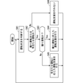
- FIG. 8 is a flowchart showing an example of the operation of the driving support device 4.
- step S11 the driving condition determination unit 2 determines the driving condition including the fanned driving and the irritated driving based on the information acquired from the vehicle sensor 8.
- step S12 the driving situation determination unit 2 determines whether or not the driving situation is a driving or annoying driving. In the case of a fanning operation or an irritating operation, the process proceeds to step S13. On the other hand, if it is not a fanning operation or an irritating operation, the process proceeds to step S16.
- step S13 the driving situation determination unit 2 determines whether or not the driving is a fanning operation. In the case of the fanning operation, the process proceeds to step S14. On the other hand, if it is not a fanning operation, the process proceeds to step S15.
- step S14 the support control unit 3 provides driving support according to the fanning operation. For example, when the driving situation determination unit 2 determines that the specific action shown in FIGS. 3 to 7 is a driving operation, the support control unit 3 instructs the display output control unit 6 to display a strong display message, and controls the voice output. Do not instruct part 7. The display output control unit 6 controls the display 9 so as to display a strong display message. As a result, a strong display message is displayed on the display 9.
- step S15 the support control unit 3 provides driving support according to the frustrated driving.
- the support control unit 3 instructs the display output control unit 6 to display a weak display message, and outputs support information. Instruct the voice output control unit 7 to output voice.
- the display output control unit 6 controls the display 9 so as to display a weak display message.
- the voice output control unit 7 controls the speaker 10 so as to output the support information having the same content as the display message by voice. As a result, a weak display message is displayed on the display 9, and support information having the same content as the display message is output by voice from the speaker 10.
- step S16 the support control unit 3 does not provide driving support. That is, the support control unit 3 does not instruct the display output control unit 6 and the audio output control unit 7.
- FIG. 9 is a block diagram showing an example of the configuration of the driving support device 11 according to the modified example.
- the driving support device 11 is characterized in that the output control unit 5 has a video recording control unit 12.
- the video recording control unit 12 is connected to the drive recorder 13. Since other configurations and operations are the same as those of the driving support device 4 shown in FIG. 2, detailed description thereof will be omitted here.
- the video recording control unit 12 controls the drive recorder 13 so as to record an image of the driving condition when the driving condition determination unit 2 determines that the driving is a fanning operation or an irritated driving according to an instruction from the support control unit 3. Further, the video recording control unit 12 may control to record a video of the driving status when the driving status determining unit 2 determines that the driving is a fanning operation or an irritated operation on an external server (not shown).
- the drive recorder 13 records an image of the driving situation of the own vehicle according to an instruction from the image recording control unit 12.
- the image of the driving situation of the own vehicle may be taken by a camera included in the vehicle sensor 8 or may be taken by a camera (not shown) included in the drive recorder 13.
- the support control unit 3 instructs the display output control unit 6 as described above, and the own vehicle performs the driving operation.
- the video recording control unit 12 is instructed to record a video of the driving situation at the time of the trip.
- the video recording control unit 12 controls the drive recorder 13 so as to record a video of the driving situation when the own vehicle is driving in a fan.
- the drive recorder 13 records an image of the driving situation when the own vehicle is driving in a fanned manner.
- Such processing is performed in step S14 of FIG.
- the "recording only" of the drive recorder performs the process of only recording the image on the drive recorder 13.
- the support control unit 3 causes the display output control unit 6 and the voice output control unit 7 as described above. Instruct the video recording control unit 12 to record an image of the driving situation when the own vehicle is irritated and driven. As a result, the drive recorder 13 records an image of the driving situation when the own vehicle is irritated and driven. Such processing is performed in step S15 of FIG.
- the "recording / video" of the drive recorder is not only the process of recording the video on the drive recorder 13, but also the video recorded on the drive recorder 13 for the driver when the own vehicle is stopped. Inquire whether to confirm. In this case, for example, "A video of the driving situation when it is determined to be annoyed driving is recorded. Do you want to check the recorded video? Yes / No" may be displayed.
- the driver can check the video by operating the drive recorder in the own vehicle.
- the driver can check the video recorded on the drive recorder using a tablet device such as a smartphone.
- the video stored in the cloud server may be transmitted to the tablet device, or the video may be transmitted from the drive recorder to the tablet device.
- the driving situation determination unit 2 determines whether or not the own vehicle has performed a driving or annoying driving, and the support control unit 3 responds to the driving or annoying driving.
- the output control unit 5 is controlled so as to provide driving support. This makes it possible to provide appropriate driving support to the driver who has performed a fanning operation or an irritated operation.
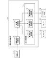
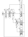
- FIG. 10 is a block diagram showing an example of the configuration of the driving support device 14 according to the second embodiment.
- the driving support device 14 is characterized in that the output control unit 5 has a travel output control unit 15.
- the travel output control unit 15 is connected to a GNSS (Global Navigation Satellite System) system 16 and a travel control device 17.
- GNSS Global Navigation Satellite System
- the driving situation determination unit 2 determines whether the irritated driving is temporary or continuous. Since other configurations and operations are the same as those of the driving support device 4 shown in FIG. 2, detailed description thereof will be omitted here.
- the GNSS system 16 acquires map information from a map database (not shown), for example, and acquires the current position information of the own vehicle.
- the travel output control unit 15 controls the travel control device 17 so as to automatically control the travel of its own vehicle by using the information acquired from the GNSS system 16 in accordance with the instruction from the support control unit 3. Specifically, the travel output control unit 15 controls the travel control device 17 so as to automatically control the travel of the own vehicle based on the map information acquired from the GNSS system 16 and the current position information of the own vehicle. The travel control device 17 automatically controls the travel of the own vehicle according to the instruction from the travel output control unit 15.
- the driving status determination unit 2 determines the driving status including the agitated driving and the irritated driving based on the information acquired from the vehicle sensor 8. Further, when the driving situation determination unit 2 determines that the irritated operation is irritated, it determines whether the irritated operation is temporary or continuous. The driving situation determination unit 2 may determine the driving situation by further considering the map information acquired from the GNSS system 16 and the current position information of the own vehicle.
- the support control unit 3 has a display output control unit 6, a voice output control unit 7, and a travel output control unit so as to provide driving support corresponding to each of a fanning operation, a temporary irritation operation, and a continuous irritation operation. 15 is controlled.
- FIGS. 11 to 15 are the same as those in FIGS. 3 to 7 except for the driving support item "vehicle running control" and the frustrated driving "continuous", the description thereof is omitted here.
- the support control unit 3 instructs the travel output control unit 15 to automatically control the travel of the own vehicle only when the driving status determination unit 2 determines that the driving is continuous irritation.
- the travel output control unit 15 controls the travel control device 17 so as to automatically control the travel of the own vehicle by using the information acquired from the GNSS system 16.
- the travel control device 17 automatically controls the travel of the own vehicle so as to travel at a legal speed or less.
- the display 9 may show on the map that there is an empty space at the destination of the own vehicle.
- the travel control device 17 may be controlled so that the own vehicle automatically moves to an empty space existing in the travel destination of the own vehicle, or may be controlled so that the own vehicle automatically changes lanes. good.
- the travel control device 17 controls so as to keep the inter-vehicle distance from the adjacent other vehicle at a constant distance.
- the travel control device 17 controls to decelerate and move to the next lane.
- the travel control device 17 controls so as to keep the distance between the vehicle and the vehicle in front constant.
- the travel control device 17 controls so as to keep the distance between the vehicle and the vehicle behind the vehicle constant.
- the support control unit 3 controls the display output control unit 6 so as to make the display message different according to each of the temporary irritated operation and the continuous irritated operation.
- the display output control unit 6 controls the display 9 to display a weak display message in the case of a temporary irritated operation and a strong display message in the case of a continuous irritated operation.
- the contents of the weak display message and the strong display message in FIGS. 11 to 15 are the same as those in FIGS. 3 to 7.
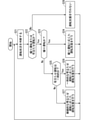
- FIG. 16 is a flowchart showing an example of the operation of the driving support device 14. Since steps S21 to S24 in FIG. 16 correspond to steps S11 to S14 in FIG. 8, and step S28 in FIG. 16 corresponds to step S16 in FIG. 8, description thereof will be omitted here. Hereinafter, steps S25 to S27 will be described.
- step S25 the driving situation determination unit 2 determines whether or not the irritated driving is temporary. If the irritated operation is temporary, the process proceeds to step S26. On the other hand, if the irritated operation is not temporary, that is, if the irritated operation is continuous, the process proceeds to step S27.
- step S26 the support control unit 3 provides driving support according to the temporary irritated driving.
- the support control unit 3 instructs the display output control unit 6 to display a weak display message. Instruct the voice output control unit 7 to output the support information by voice. At this time, the support control unit 3 does not instruct the travel output control unit 15.
- the display output control unit 6 controls the display 9 so as to display a weak display message.
- the voice output control unit 7 controls the speaker 10 so as to output the support information having the same content as the display message by voice. As a result, a weak display message is displayed on the display 9, and support information having the same content as the display message is output by voice from the speaker 10.
- step S27 the support control unit 3 provides driving support according to continuous irritated driving.
- the support control unit 3 instructs the display output control unit 6 to display a strong display message.
- the voice output control unit 7 is instructed to output the support information by voice
- the travel output control unit 15 is instructed to automatically control the travel of the own vehicle.
- the display output control unit 6 controls the display 9 so as to display a strong display message.
- the voice output control unit 7 controls the speaker 10 so as to output the support information having the same content as the display message by voice.
- the travel output control unit 15 controls the travel control device 17 so as to automatically control the travel of the own vehicle. As a result, a weak display message is displayed on the display 9, and support information having the same content as the display message is output by voice from the speaker 10. Further, the travel control device 17 automatically controls the travel of the own vehicle.
- FIG. 17 is a block diagram showing an example of the configuration of the driving support device 18 according to the modified example.
- the driving support device 18 is characterized in that the output control unit 5 has a video recording control unit 12.
- Other configurations and operations are the same as those of the driving support device 14 shown in FIG. 10, and thus description thereof will be omitted here.
- the video recording control unit 12 controls the drive recorder 13 so as to record an image of the driving condition when the driving condition determination unit 2 determines that the driving is a fanning operation or an irritated driving according to an instruction from the support control unit 3.
- the drive recorder 13 records an image of the driving situation of the own vehicle according to an instruction from the image recording control unit 12.
- the support control unit 3 instructs the display output control unit 6 as described above, and the own vehicle performs the driving operation.
- the video recording control unit 12 is instructed to record a video of the driving situation at the time of the trip.
- the processing is the same as the processing of the video recording control unit 12 of FIG.
- the support control unit 3 has the display output control unit 6 and the display output control unit 6 as described above.
- the audio output control unit 7 is instructed, and the video recording control unit 12 is instructed to record an image of the driving situation when the own vehicle performs a temporary or continuous irritated driving.
- the processing is the same as the processing of the video recording control unit 12 of FIG.
- the driving situation determination unit 2 determines whether or not the own vehicle has been driven in a hurry or in an irritated manner, and in the case of the irritated driving, it is temporary or continuous. Judge whether it is. Further, the support control unit 3 controls the output control unit 5 so as to provide driving support according to each of the fanning operation, the temporary irritation operation, or the continuous irritation operation. This makes it possible to provide appropriate driving support to a driver who has performed a fanning operation, a temporary irritation operation, or a continuous irritation operation.
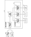
- FIG. 18 is a block diagram showing an example of the configuration of the driving support device 19 according to the third embodiment.
- the driving support device 19 is characterized in that the driving situation determination unit 2 determines the driving situation. Since other configurations and basic operations are the same as those of the first embodiment or the second embodiment, detailed description thereof will be omitted here.
- the driving status determination unit 2 is connected to the vehicle sensor 8 and the vehicle body device 20.
- the vehicle sensor 8 is the same as the vehicle sensor 8 described in the first and second embodiments.
- the vehicle body device 20 includes a horn that emits a warning sound, a headlight that irradiates light toward the front, and the like.
- the driving status determination unit 2 determines the driving status including the fanned driving and the irritated driving based on the information acquired from the vehicle sensor 8 and the vehicle body device 20. Further, when the driving situation determination unit 2 determines that the irritated operation is irritated, it determines whether the irritated operation is temporary or continuous.
- the driving situation determination unit 2 determines a driving or annoying driving based on the information acquired from the vehicle body device 20, for example, "warning sound or outburst of lighting" shown in FIG. 19 can be mentioned. Be done.
- each specific action shown in FIG. 19 is an example, and other driving may be a specific action.
- the "warning sound or outburst of lighting" shown in FIG. 19 means that the driver of the own vehicle frequently uses the warning sound for the other vehicle in front, or the driver of the own vehicle passes the other vehicle in front. It is to make heavy use of blinking lights.
- the driving situation determination unit 2 determines whether or not the own vehicle and the other vehicle are in the same lane based on the information of the lane in which the own vehicle and the other vehicle are traveling acquired from the vehicle sensor 8. .. Further, the driving status determination unit 2 determines whether or not the warning sound or the blinking of the lighting is frequently used based on the usage status of the warning sound or the lighting acquired from the vehicle body device 20.
- the driving situation determination unit 2 determines that the driver of the own vehicle is making a "warning sound or lighting outburst", it is based on what kind of "warning sound or lighting outburst" is being made. Determine whether you are driving in a horn or in a hurry.
- the driving situation determination unit 2 determines that the driver of the own vehicle is performing the driving when the driver of the own vehicle repeatedly executes the "warning sound or the outburst of lighting" more than a predetermined number of times. .. For example, the driving situation determination unit 2 determines that the driver is driving in a hurry when the warning sound is repeatedly emitted to the same other vehicle four times or more. Further, the driving situation determination unit 2 determines that the driving is being performed when the warning sound for 4 seconds or longer is repeatedly emitted for a predetermined number of times or more.
- the driving situation determination unit 2 states that the driver of the own vehicle is temporarily or continuously irritating when the driver of the own vehicle is temporarily or continuously executing the "warning sound or outburst of lighting". to decide. For example, the driving situation determination unit 2 determines that the driver is temporarily irritated when the warning sound is emitted for 1 to 2 seconds. Further, the driving situation determination unit 2 determines that the driver is continuously irritated when the warning sound is emitted for 2 to 4 seconds. Further, the driving condition determination unit 2 determines that the driver is continuously irritated when the warning sound is emitted two or three times.
- the support control unit 3 controls the display output control unit 6 and the voice output control unit 7 so as to provide driving support corresponding to each of the fanning operation, the temporary irritation operation, and the continuous irritation operation.
- the support control unit 3 displays a display output control unit so as to display a strong display message. Instruct 6. At this time, the support control unit 3 does not instruct the voice output control unit 7.
- the display output control unit 6 controls the display 9 so as to display a strong display message as support information for the driver.
- the display 9 displays a display message such as "Warning: It is determined that the horn has been honked multiple times. Please stop honking excessively.”
- the support control unit 3 instructs the display output control unit 6 to display a weak display message. Instruct the voice output control unit 7 to output the support information by voice.
- the display output control unit 6 controls the display 9 so as to display a weak display message as support information for the driver.
- the display 9 displays a display message such as "Caution: It is determined that the horn has been sounded multiple times. Please use an appropriate warning sound.”
- the voice output control unit 7 controls the speaker 10 so as to output the support information having the same content as the display message by voice. Support information having the same content as the display message is output by voice from the speaker 10.
- FIG. 20 is a flowchart showing an example of the operation of the driving support device 19. Since steps S33 to S38 in FIG. 20 correspond to steps S23 to S28 in FIG. 16, description thereof will be omitted here. Hereinafter, steps S31 and S32 will be described.
- step S31 the driving condition determination unit 2 determines the driving condition including the fanned driving and the irritated driving based on the information acquired from the vehicle sensor 8 and the vehicle body device 20.
- step S32 the driving situation determination unit 2 determines whether or not the driving situation is a driving or annoying driving. In the case of a fanning operation or an irritating operation, the process proceeds to step S33. On the other hand, if it is not a fanning operation or an irritating operation, the process proceeds to step S38.
- FIG. 21 is a block diagram showing an example of the configuration of the driving support device 21 according to the modified example.
- the driving support device 21 is characterized in that the output control unit 5 has a video recording control unit 12.
- Other configurations and operations are the same as those of the driving support device 14 shown in FIG. 10, and thus description thereof will be omitted here.
- the video recording control unit 12 controls the drive recorder 13 so as to record an image of the driving condition when the driving condition determination unit 2 determines that the driving is a fanning operation or an irritated driving according to an instruction from the support control unit 3.
- the drive recorder 13 records an image of the driving situation of the own vehicle according to an instruction from the image recording control unit 12.
- the support control unit 3 instructs the display output control unit 6 as described above, and the own vehicle performs the driving operation.
- the video recording control unit 12 is instructed to record the video of the driving situation at that time.
- the processing is the same as the processing of the video recording control unit 12 of FIG.
- the support control unit 3 has the display output control unit 6 and the voice output as described above.
- the control unit 7 is instructed, and the video recording control unit 12 is instructed to record an image of the driving situation when the own vehicle performs a temporary or continuous irritated operation.
- the process is the same as that of the video recording control unit 12 of FIG.
- the driving situation determination unit 2 determines whether or not the own vehicle has been driven or irritated based on the information acquired from the vehicle body device 20, and is irritated. In the case of road rage, determine whether it is temporary or continuous. Further, the support control unit 3 controls the output control unit 5 so as to provide driving support according to each of the fanning operation, the temporary irritation operation, or the continuous irritation operation. This makes it possible to provide appropriate driving support to a driver who has performed a fanning operation, a temporary irritation operation, or a continuous irritation operation.
- FIG. 22 is a block diagram showing an example of the configuration of the driving support device 22 according to the fourth embodiment.
- the output control unit 5 has only the video recording control unit 12, and is characterized in that the driving status determination unit 2 determines the driving status.
- the driving status determination unit 2 is connected to the vehicle sensor 8 and the peripheral detection device 23.
- the vehicle sensor 8 is the same as the vehicle sensor 8 described in the first to third embodiments.
- the peripheral detection device 23 includes a microphone that collects a warning sound emitted by another vehicle to the own vehicle, an illuminance sensor that detects light irradiation such as passing performed by the other vehicle to the own vehicle, and the like. That is, the peripheral detection device 23 detects the actions of other vehicles with respect to the own vehicle.
- the driving status determination unit 2 determines the driving status including the fanned driving and the irritated driving based on the information acquired from the vehicle sensor 8 and the peripheral detection device 23. Specifically, the driving situation determination unit 2 determines whether or not another vehicle exists in the vicinity of the own vehicle based on the information acquired from the vehicle sensor 8. Further, the driving situation determination unit 2 determines whether or not the other vehicle has irradiated the own vehicle with light such as a warning sound or passing based on the information acquired from the peripheral detection device 23. Then, when the driving situation determination unit 2 determines that the other vehicle has irradiated the own vehicle with light such as a warning sound or passing, the driver of the own vehicle is driving or irritating the other vehicle. Judge that you have done.
- the driving situation determination unit 2 determines a driving or annoying driving based on the information acquired from the peripheral detection device 23, for example, "detection of the action of another vehicle" shown in FIG. 23 can be mentioned. Will be.
- the specific behavior shown in FIG. 23 is an example, and other driving may be a specific behavior.
- the "detection of the action of another vehicle" shown in FIG. 23 detects that another vehicle existing in the vicinity of the own vehicle emits a warning sound to the own vehicle, or passes the own vehicle, or the like. It is to detect that it is irradiated with the light of.
- the driving status determination unit 2 determines the usage status of the warning sound or lighting of another vehicle with respect to the own vehicle acquired from the peripheral detection device 23. Then, the driving situation determination unit 2 performs either a fanning driving or an irritated driving by the driver of the own vehicle based on how the other vehicle uses the warning sound or the lighting for the own vehicle. Judge if you are.
- the driving situation determination unit 2 repeatedly executes light irradiation such as a warning sound or passing to the own vehicle by another vehicle existing in the vicinity of the own vehicle more than a predetermined number of times. In this case, it is determined that the driver of the own vehicle is driving in a horn. Further, the driving situation determination unit 2 is a driver of the own vehicle when another vehicle existing in the vicinity of the own vehicle temporarily irradiates the own vehicle with light such as a warning sound or passing. Judges that he is driving annoyed.
- the support control unit 3 controls the video recording control unit 12 so as to provide driving support corresponding to each of the fanning operation and the irritating operation.
- the support control unit 3 is the self before receiving an action from another vehicle.
- the video recording control unit 12 is instructed to record a video of the driving situation of the vehicle.
- the processing is the same as the processing of the video recording control unit 12 of FIG.
- the support control unit 3 records the image of the driving condition of the own vehicle before receiving the action from another vehicle. Instruct the video recording control unit 12.
- the processing is the same as the processing of the video recording control unit 12 of FIG. In this case, when the own vehicle is stopped, the driver is inquired whether or not to check the image recorded on the drive recorder 13.
- FIG. 24 is a flowchart showing an example of the operation of the driving support device 22.
- step S41 the driving condition determination unit 2 determines the driving condition including the fanning operation and the irritated operation based on the information acquired from the vehicle sensor 8 and the peripheral detection device 23.
- the driving situation determined here is the driving situation of the own vehicle.
- step S42 the driving condition determination unit 2 determines whether or not the driving condition of the own vehicle is a fanned driving or an irritated driving. In the case of a fanning operation or an irritating operation, the process proceeds to step S43. On the other hand, if it is not a fanning operation or an irritating operation, the process proceeds to step S46.
- step S43 the driving situation determination unit 2 determines whether or not the driving is a fanning operation. In the case of the fanning operation, the process proceeds to step S44. On the other hand, if it is not a fanning operation, the process proceeds to step S45.
- step S44 the support control unit 3 provides driving support according to the fanning operation.
- the support control unit 3 records a video of the driving situation of the own vehicle before receiving an action from another vehicle.
- the video recording control unit 12 is instructed to do so.
- the video recording control unit 12 records a video of the driving situation of the own vehicle before receiving an act from another vehicle.
- the drive recorder 13 records an image of the driving situation of the own vehicle before receiving an act from another vehicle.
- step S45 the support control unit 3 provides driving support according to the frustrated driving.
- the support control unit 3 displays an image of the driving status of the own vehicle before receiving an action from another vehicle. Instruct the video recording control unit 12 to record.
- the video recording control unit 12 records a video of the driving situation of the own vehicle before receiving an act from another vehicle.
- the drive recorder 13 records an image of the driving situation of the own vehicle before receiving an act from another vehicle. Further, when the own vehicle is stopped, the driver is inquired whether or not to check the image recorded on the drive recorder 13.
- step S46 the support control unit 3 does not provide driving support. That is, the support control unit 3 does not instruct the video recording control unit 12.
- the driving situation determination unit 2 determines whether or not the own vehicle has been driven or irritated based on the information acquired from the peripheral detection device 23. Further, the support control unit 3 controls the output control unit 5 so as to provide driving support according to each of the driving operation and the irritating operation. This makes it possible to provide appropriate driving support to the driver who has performed a fanning operation or an irritated operation.
- FIG. 25 is a block diagram showing an example of the configuration of the driving support device 24 according to the fifth embodiment. Since each component and operation of the driving support device 24 is a configuration and operation in which the driving support devices described in each of the first to fourth embodiments are combined, the description thereof will be omitted here.
- Each function of the operation status determination unit 2, the support control unit 3, the display output control unit 6, and the voice output control unit 7 in the operation support device 4 described in the first embodiment is realized by the processing circuit. That is, the driving support device 4 determines the driving situation of the driver of the own vehicle, controls the driving support according to the driving in a hurry or the frustrated driving, controls the display of the support information, and outputs the support information by voice.
- a processing circuit for performing control is provided.
- the processing circuit may be dedicated hardware, and may be a processor (CPU, central processing unit, processing unit, arithmetic unit, microprocessor, microprocessor, DSP (Digital Signal Processor)) that executes a program stored in the memory. It may be).
- the processing circuit 25 may be, for example, a single circuit, a composite circuit, a programmed processor, a parallel programmed processor, or an ASIC (Application Specific Integrated Circuit). , FPGA (Field Programmable Gate Array), or a combination of these.
- the functions of the operation status determination unit 2, the support control unit 3, the display output control unit 6, and the audio output control unit 7 may be realized by the processing circuit 25, respectively, and the functions may be collectively realized by one processing circuit 25. You may.
- the functions of the operation status determination unit 2, the support control unit 3, the display output control unit 6, and the audio output control unit 7 are software, firmware, or software and firmware. It is realized by the combination with.
- the software or firmware is written as a program and stored in the memory 27.
- the processor 26 realizes each function by reading and executing the program recorded in the memory 27. That is, the driving support device 4 performs a step of determining the driving situation of the driver of the own vehicle, a step of controlling driving support according to a fanning driving or an irritated driving, a step of controlling to display support information, and support information.
- a memory 27 for storing a program for which a step for controlling audio output is to be executed as a result is provided.
- the memory is, for example, non-volatile or volatile such as RAM (RandomAccessMemory), ROM (ReadOnlyMemory), flash memory, EPROM (ErasableProgrammableReadOnlyMemory), and EEPROM (ElectricallyErasableProgrammableReadOnlyMemory). It may be a sex semiconductor memory, a magnetic disk, a flexible disk, an optical disk, a compact disk, a DVD (DigitalVersatileDisc), or any storage medium that will be used in the future.
- the support control unit 3, the display output control unit 6, and the audio output control unit 7 are realized by dedicated hardware, and other functions are provided by software or firmware. It may be realized by.
- the processing circuit can realize each of the above-mentioned functions by hardware, software, firmware, or a combination thereof.
- the driving support device 11 the driving support device 14, the driving support device 18, and the driving support device 18 described in each of the first to fifth embodiments have been described above. The same applies to the hardware configurations of the driving support device 19, the driving support device 21, and the driving support device 24.
- the driving support device described above is a system in which not only an in-vehicle navigation device, that is, a car navigation device, but also a PND (Portable Navigation Device) that can be mounted on a vehicle, a server provided outside the vehicle, and the like are appropriately combined. It can also be applied to a navigation device constructed as a system or a device other than the navigation device constructed as a system. In this case, each function or each component of the driving support device is distributed and arranged in each function for constructing the system.
- PND Portable Navigation Device
- the function of the driving support device can be arranged on the server.
- the vehicle includes a vehicle sensor 8, a display 9, and a speaker 10.
- the server 28 includes an operation status determination unit 2, a support control unit 3, a display output control unit 6, and a voice output control unit 7. With such a configuration, a driving support system can be constructed.
- software that executes the operation in the above embodiment may be incorporated into, for example, a server.
- the driving support method realized by the server executing this software is the driving that the driver of the own vehicle intentionally performs with respect to the other vehicle and the driving of the other vehicle that is not the intention of the driver of the own vehicle. Judging the driving situation including irritated driving that irritates the person, and performing control to support the driver's driving of the own vehicle according to each of the case where it is determined to be irritated driving and the case where it is determined to be irritated driving. including.
- each embodiment can be freely combined, and each embodiment can be appropriately modified or omitted.
Landscapes
- Engineering & Computer Science (AREA)
- Automation & Control Theory (AREA)
- Transportation (AREA)
- Mechanical Engineering (AREA)
- Human Computer Interaction (AREA)
- Physics & Mathematics (AREA)
- Mathematical Physics (AREA)
- Traffic Control Systems (AREA)
Priority Applications (3)
| Application Number | Priority Date | Filing Date | Title |
|---|---|---|---|
| PCT/JP2020/031441 WO2022038741A1 (ja) | 2020-08-20 | 2020-08-20 | 運転支援装置および運転支援方法 |
| US18/015,243 US20230294720A1 (en) | 2020-08-20 | 2020-08-20 | Drive assist apparatus and drive assist method |
| JP2022543220A JP7699594B2 (ja) | 2020-08-20 | 2020-08-20 | 運転支援装置および運転支援方法 |
Applications Claiming Priority (1)
| Application Number | Priority Date | Filing Date | Title |
|---|---|---|---|
| PCT/JP2020/031441 WO2022038741A1 (ja) | 2020-08-20 | 2020-08-20 | 運転支援装置および運転支援方法 |
Publications (1)
| Publication Number | Publication Date |
|---|---|
| WO2022038741A1 true WO2022038741A1 (ja) | 2022-02-24 |
Family
ID=80323560
Family Applications (1)
| Application Number | Title | Priority Date | Filing Date |
|---|---|---|---|
| PCT/JP2020/031441 Ceased WO2022038741A1 (ja) | 2020-08-20 | 2020-08-20 | 運転支援装置および運転支援方法 |
Country Status (3)
| Country | Link |
|---|---|
| US (1) | US20230294720A1 (https=) |
| JP (1) | JP7699594B2 (https=) |
| WO (1) | WO2022038741A1 (https=) |
Cited By (2)
| Publication number | Priority date | Publication date | Assignee | Title |
|---|---|---|---|---|
| WO2024087887A1 (zh) * | 2022-10-25 | 2024-05-02 | 中国第一汽车股份有限公司 | 鲁莽驾驶行为标记方法、车辆、云端服务器和存储介质 |
| WO2026028451A1 (ja) * | 2024-08-02 | 2026-02-05 | 日産自動車株式会社 | 運転支援方法及び運転支援装置 |
Families Citing this family (1)
| Publication number | Priority date | Publication date | Assignee | Title |
|---|---|---|---|---|
| JP2023136794A (ja) * | 2022-03-17 | 2023-09-29 | 株式会社Subaru | 車両用運転支援装置及び車両用運転支援方法 |
Citations (7)
| Publication number | Priority date | Publication date | Assignee | Title |
|---|---|---|---|---|
| JP2006205773A (ja) * | 2005-01-25 | 2006-08-10 | Fujitsu Ten Ltd | 運転支援装置 |
| JP2010257071A (ja) * | 2009-04-22 | 2010-11-11 | Toyota Motor Corp | 車両制御装置 |
| JP2014191632A (ja) * | 2013-03-27 | 2014-10-06 | Fuji Heavy Ind Ltd | 車線変更支援装置 |
| JP2019119371A (ja) * | 2018-01-09 | 2019-07-22 | 三菱自動車工業株式会社 | 煽り運転解消システム |
| JP2020024580A (ja) * | 2018-08-07 | 2020-02-13 | 矢崎エナジーシステム株式会社 | 運転評価装置および車載器 |
| JP2020052751A (ja) * | 2018-09-27 | 2020-04-02 | ダイハツ工業株式会社 | あおり運転検出装置 |
| JP2020087140A (ja) * | 2018-11-28 | 2020-06-04 | 京セラ株式会社 | 画像処理装置、撮像装置、移動体及び画像処理方法 |
Family Cites Families (5)
| Publication number | Priority date | Publication date | Assignee | Title |
|---|---|---|---|---|
| JP4743159B2 (ja) * | 2007-05-14 | 2011-08-10 | 株式会社デンソー | 車両制御装置 |
| US9499139B2 (en) * | 2013-12-05 | 2016-11-22 | Magna Electronics Inc. | Vehicle monitoring system |
| US10967876B2 (en) * | 2016-03-09 | 2021-04-06 | Honda Motor Co., Ltd. | Vehicle control system, vehicle control method, and vehicle control program |
| DE112019000065B4 (de) * | 2018-02-02 | 2025-01-09 | Nvidia Corporation | Sicherheitsprozeduranalyse zur hindernisvermeidung in einem autonomen fahrzeug |
| US20220319322A1 (en) * | 2019-02-14 | 2022-10-06 | Mitsubishi Electric Corporation | Drive assist apparatus and drive assist method |
-
2020
- 2020-08-20 JP JP2022543220A patent/JP7699594B2/ja active Active
- 2020-08-20 US US18/015,243 patent/US20230294720A1/en active Pending
- 2020-08-20 WO PCT/JP2020/031441 patent/WO2022038741A1/ja not_active Ceased
Patent Citations (7)
| Publication number | Priority date | Publication date | Assignee | Title |
|---|---|---|---|---|
| JP2006205773A (ja) * | 2005-01-25 | 2006-08-10 | Fujitsu Ten Ltd | 運転支援装置 |
| JP2010257071A (ja) * | 2009-04-22 | 2010-11-11 | Toyota Motor Corp | 車両制御装置 |
| JP2014191632A (ja) * | 2013-03-27 | 2014-10-06 | Fuji Heavy Ind Ltd | 車線変更支援装置 |
| JP2019119371A (ja) * | 2018-01-09 | 2019-07-22 | 三菱自動車工業株式会社 | 煽り運転解消システム |
| JP2020024580A (ja) * | 2018-08-07 | 2020-02-13 | 矢崎エナジーシステム株式会社 | 運転評価装置および車載器 |
| JP2020052751A (ja) * | 2018-09-27 | 2020-04-02 | ダイハツ工業株式会社 | あおり運転検出装置 |
| JP2020087140A (ja) * | 2018-11-28 | 2020-06-04 | 京セラ株式会社 | 画像処理装置、撮像装置、移動体及び画像処理方法 |
Cited By (2)
| Publication number | Priority date | Publication date | Assignee | Title |
|---|---|---|---|---|
| WO2024087887A1 (zh) * | 2022-10-25 | 2024-05-02 | 中国第一汽车股份有限公司 | 鲁莽驾驶行为标记方法、车辆、云端服务器和存储介质 |
| WO2026028451A1 (ja) * | 2024-08-02 | 2026-02-05 | 日産自動車株式会社 | 運転支援方法及び運転支援装置 |
Also Published As
| Publication number | Publication date |
|---|---|
| US20230294720A1 (en) | 2023-09-21 |
| JPWO2022038741A1 (https=) | 2022-02-24 |
| JP7699594B2 (ja) | 2025-06-27 |
Similar Documents
| Publication | Publication Date | Title |
|---|---|---|
| US10793066B2 (en) | System and method for vehicular alert | |
| CN108602513B (zh) | 行驶辅助装置 | |
| JP2017178267A (ja) | 運転支援方法およびそれを利用した運転支援装置、自動運転制御装置、車両、プログラム | |
| WO2022038741A1 (ja) | 運転支援装置および運転支援方法 | |
| JP2006113918A (ja) | 運転支援装置 | |
| JP2022159189A (ja) | 運転支援装置 | |
| US11745745B2 (en) | Systems and methods for improving driver attention awareness | |
| JP2016005932A (ja) | 車両の制御装置、及び車両 | |
| CN111278702A (zh) | 车辆控制装置、具有该车辆控制装置的车辆以及控制方法 | |
| JP2021111155A (ja) | 運転支援装置 | |
| JP2020009285A (ja) | 運転支援装置,方法,プログラム | |
| US20160185290A1 (en) | Navigation device, navigation method, and computer program product | |
| JP2024090436A (ja) | 情報処理装置 | |
| JP4873255B2 (ja) | 車両用報知システム | |
| JP2008191890A (ja) | 安全走行支援装置 | |
| JP2021046182A (ja) | 自動運転車 | |
| CN115140062B (zh) | 驾驶辅助装置 | |
| JP2017054441A (ja) | 警報制御装置 | |
| CN114940171A (zh) | 驾驶辅助装置 | |
| JP2019048521A (ja) | 報知装置 | |
| CN113615256A (zh) | 控制装置、控制方法以及程序 | |
| JP6983335B2 (ja) | 運転判定装置および運転判定方法 | |
| US20250145173A1 (en) | Autonomous driving control apparatus and method thereof | |
| JP6584676B2 (ja) | 報知制御装置および報知制御方法 | |
| JP6337761B2 (ja) | 注意喚起制御装置 |
Legal Events
| Date | Code | Title | Description |
|---|---|---|---|
| 121 | Ep: the epo has been informed by wipo that ep was designated in this application |
Ref document number: 20950306 Country of ref document: EP Kind code of ref document: A1 |
|
| ENP | Entry into the national phase |
Ref document number: 2022543220 Country of ref document: JP Kind code of ref document: A |
|
| NENP | Non-entry into the national phase |
Ref country code: DE |
|
| 122 | Ep: pct application non-entry in european phase |
Ref document number: 20950306 Country of ref document: EP Kind code of ref document: A1 |