WO2022009431A1 - 包装用容器 - Google Patents
包装用容器 Download PDFInfo
- Publication number
- WO2022009431A1 WO2022009431A1 PCT/JP2020/027118 JP2020027118W WO2022009431A1 WO 2022009431 A1 WO2022009431 A1 WO 2022009431A1 JP 2020027118 W JP2020027118 W JP 2020027118W WO 2022009431 A1 WO2022009431 A1 WO 2022009431A1
- Authority
- WO
- WIPO (PCT)
- Prior art keywords
- container body
- packaging container
- shape
- mounting
- mounting surfaces
- Prior art date
- Legal status (The legal status is an assumption and is not a legal conclusion. Google has not performed a legal analysis and makes no representation as to the accuracy of the status listed.)
- Ceased
Links
Images


Classifications
-
- B—PERFORMING OPERATIONS; TRANSPORTING
- B65—CONVEYING; PACKING; STORING; HANDLING THIN OR FILAMENTARY MATERIAL
- B65D—CONTAINERS FOR STORAGE OR TRANSPORT OF ARTICLES OR MATERIALS, e.g. BAGS, BARRELS, BOTTLES, BOXES, CANS, CARTONS, CRATES, DRUMS, JARS, TANKS, HOPPERS, FORWARDING CONTAINERS; ACCESSORIES, CLOSURES, OR FITTINGS THEREFOR; PACKAGING ELEMENTS; PACKAGES
- B65D1/00—Rigid or semi-rigid containers having bodies formed in one piece, e.g. by casting metallic material, by moulding plastics, by blowing vitreous material, by throwing ceramic material, by moulding pulped fibrous material or by deep-drawing operations performed on sheet material
- B65D1/34—Trays or like shallow containers
- B65D1/36—Trays or like shallow containers with moulded compartments or partitions
-
- B—PERFORMING OPERATIONS; TRANSPORTING
- B65—CONVEYING; PACKING; STORING; HANDLING THIN OR FILAMENTARY MATERIAL
- B65D—CONTAINERS FOR STORAGE OR TRANSPORT OF ARTICLES OR MATERIALS, e.g. BAGS, BARRELS, BOTTLES, BOXES, CANS, CARTONS, CRATES, DRUMS, JARS, TANKS, HOPPERS, FORWARDING CONTAINERS; ACCESSORIES, CLOSURES, OR FITTINGS THEREFOR; PACKAGING ELEMENTS; PACKAGES
- B65D85/00—Containers, packaging elements or packages, specially adapted for particular articles or materials
- B65D85/50—Containers, packaging elements or packages, specially adapted for particular articles or materials for living organisms, articles or materials sensitive to changes of environment or atmospheric conditions, e.g. land animals, birds, fish, water plants, non-aquatic plants, flower bulbs, cut flowers or foliage
Definitions
- the present invention relates to a packaging container in which contained items such as nigiri sushi can be arranged so as to attract the attention of the purchaser.
- nigiri sushi so-called packed sushi, housed in thin plastic containers.
- Many of the containers used for packed sushi have a flat bottom, and the nigiri sushi served in such containers is visually monotonous with the ingredients arranged regularly on a flat surface, and the buyer's willingness to buy. I could't say that it stimulated.
- chirashizushi and the like can be seen by devising the arrangement of the ingredients to improve the appearance, appealing to the eyes of the buyer, stimulating the purchase motivation, and may be purchased unintentionally. Even with packed sushi, if the arrangement can stimulate purchasing motivation, it will be possible to contribute to increased sales.
- Patent Document 1 has zigzag-like unevenness on the surface side by arranging nigiri sushi in an inclined state, which is visually different from the conventional one. However, it was doubtful that the individual nigiri sushi seemed to be tilted and would give a good impression to the buyer.
- an object of the present invention is to provide a packaging container that is particularly suitable for accommodating rectangular parallelepiped foodstuffs such as nigiri sushi, has appealing power to buyers, and can be arranged in an arrangement that arouses purchasing motivation. ..
- this container can make it easier to pick up contents such as nigiri sushi with chopsticks.
- the packaging container of one embodiment of the present invention is a packaging container provided with at least a container body, and a plurality of partitioned flat mounting surfaces are provided on the bottom surface of the container body, and a plurality of mounting surfaces are provided. It is characterized in that it is arranged along the length direction of the container body and has a stepped shape in which the heights of adjacent mounting surfaces are different. This mounting surface can be partitioned in a quadrangular shape.
- individual nigiri sushi can be placed on each mounting surface, for example, by providing individual mounting surfaces by dividing the bottom surface and making the heights of the adjacent mounting surfaces different so that they are stepped.
- the surface height of each nigiri sushi is different, and it looks like it sticks out upwards, so it looks voluminous, and it is possible to increase the probability that the buyer will involuntarily gaze and pick it up.
- the placed nigiri sushi sticks out, it has the advantage of being easy to pick up with chopsticks from above.
- a plurality of mounting surfaces are arranged in a mountain shape in which the intermediate mounting surface in the length direction of the container body is at the highest position, or ascend or descend in order from one end side to the other end side. It can be arranged in a staircase pattern. By arranging such a mounting surface, it is possible to enhance the appealing power to the purchaser and motivate the purchaser.
- the peripheral wall surface portion can be provided around the bottom surface portion, and the upper edge portion of the peripheral wall surface portion on the front side of the container body can be formed into a convex shape in which the intermediate portion swells in a side view or a corrugated shape in which the convex portions repeat.
- the mounting surface can be arranged in parallel in the width direction of the container body.
- the mounting surfaces arranged in the width direction of the container body can be made flush with each other, or the heights can be made different. By doing so, it is possible to load the contents in multiple rows in the width direction (depth direction), and it is possible to arrange various variations in which the heights of the contents are different while increasing the capacity, and it is possible to purchase. It is possible to enhance the appeal to the person.
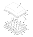
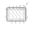
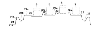
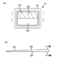
- FIG. 1 It is a perspective view in the state which the container main body and the lid body are separated in the packaging container of the 1st Embodiment of this invention. It is a top view of the container body of FIG. It is an end view cut by the line AA of FIG.
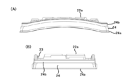
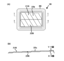
- the container body of FIG. 1 is shown, (A) is a side view of the longitudinal edge portion side (front side), and (B) is a side view of the lateral edge portion side.
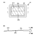
- a modification of the arrangement structure of the mounting surface in the container body of FIG. 1 is simply shown, (A) is a mountain-shaped arrangement, and (B) is an end view showing a stepped arrangement.
- FIG. 12 shows a modified example of the packaging container shown in FIG. 12, and is a perspective view of the container body. It is a top view of the container body of FIG.
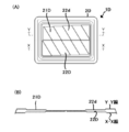
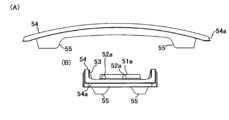
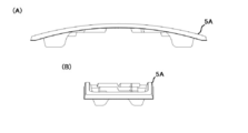
- the container body of FIG. 15 is shown, (A) is a side view of the longitudinal edge portion side (front side), and (B) is a side view of the lateral edge portion side.
- the packaging container 1 of the first embodiment of the present invention includes a container body 2 and a lid body 3.
- the packaging container 1 may be provided with at least the container body 2 and may be configured without the lid 3.
- the packaging container 1 has a rectangular parallelepiped shape, more specifically, an arch shape in which the vicinity of the middle in the length direction of the rectangular parallelepiped bulges upward.
- the packaging container 1 can contain, for example, foodstuffs, and is particularly suitable for storing rectangular parallelepiped foodstuffs such as nigiri sushi, gunkanmaki, and cut soup rolls.
- the container main body 2 has a flat rectangular parallelepiped shape, and more specifically, as shown in FIG. 4A, the flat rectangular parallelepiped has an arched shape.
- the longitudinal direction of the container body 2 will be the length direction
- the lateral direction will be the width direction
- one longitudinal edge side of the container body 2 will be described as the front side.
- the container body 2 has a rectangular shape in a plan view, but is not limited to this, and may be a square shape in a plan view, an ellipse in a plan view, an oval shape, or the like.
- the container body 2 has a bottom surface portion 21, a plurality of mounting surfaces 22 in which the bottom surface portion 21 is partitioned in a square shape, a peripheral wall surface portion 23 rising from the periphery of the bottom surface portion 21, and an upper edge portion of the peripheral wall surface portion 23 downward. It is provided with a hakama portion 24 which is folded back and also serves as a leg portion 24a.
- the bottom surface portion 21 has a rectangular shape in a plan view, a mounting portion 21a in which the mounting surfaces 22 are arranged in a stepped manner, and a groove-shaped concave groove portion provided around the mounting portion 21a. 21b and the like.
- the mounting portion 21a is formed by arranging the mounting surfaces 22 partitioned in a parallel four-sided shape in a plan view in four rows in the length direction and two rows in the width direction of the container body 2.
- each mounting surface 22 has a substantially horizontal plane shape so that an container such as individual nigiri sushi S can be placed on the mounting surface 22.
- each mounting surface 22 may be provided with a ridge-shaped partition portion 22a raised at a slightly height, so that the contained object placed on the mounting surface 22 does not easily shift and move.
- the partition portion 22a may be formed in a potch shape protruding in a conical shape.
- the mounting surface 22 is divided into parallel rectangular parallelepiped shapes in a plan view, but the present invention is not limited to this, and polygonal shapes such as a triangular shape, a rectangular shape, a pentagonal shape, and a hexagonal shape in a plan view can be used.
- the mounting surface 22 may be a slightly inclined inclined surface instead of a horizontal plane. If the mounting surface 22 is a slightly inclined inclined surface, the visibility of the nigiri sushi material is improved when the packaging container 1 on which the contents such as nigiri sushi are placed is displayed, and the consumer's willingness to purchase. Can stimulate.
- the mounting surfaces 22 are arranged along the length direction of the container body 2 so as to have a stepped shape in which the heights of the adjacent mounting surfaces 22 are different. .. Specifically, the mounting surface 22 in the middle in the length direction of the container body 2 (the second row from the right on the front side and the second row from the left on the back side) is arranged in a mountain shape at the highest position. It has been done. Further, the mounting surface 22 adjacent to the container body 2 in the width direction is flush with each other.
- the peripheral wall surface portion 23 rises vertically from the peripheral edge of the concave groove portion 21b and surrounds the bottom surface portion 21. As shown in FIG. 4, the upper edge portion of the longitudinal edge portion of the peripheral wall surface portion 23 is arched in a side view. As a result, when the container main body 2 is viewed from the side surface on the front side, it seems that the center is raised in combination with the mounting surfaces 22 arranged in a mountain shape, and it becomes easy to attract the attention of the purchaser. It is preferable that the upper edge portion of the peripheral wall surface portion 23 is located at a position slightly higher than the mounting portion 21a.
- the upper edge of the longitudinal edge of the peripheral wall surface 23 is preferably a convex shape in which the middle portion swells or a corrugated shape in which the convex portion repeats.
- the hakama portion 24 is formed by folding the upper edge portion of the peripheral wall surface portion 23 downward and is a vertical or inclined surface extending downward.
- the lower edge portion on the short edge side and the vicinity of both corners of the lower edge portion of the longitudinal edge portion are also provided as leg portions 24a to be grounded when placed on a shelf or the like.
- the lower edge portion of the hakama portion 24 on the longitudinal edge portion side has an arch shape near the middle so as not to touch the ground.
- the hakama portion 24 is provided with a fitted portion 24b that is recessed over the entire circumference toward the inside of the container body 2 so that the lid 3 can be fitted.
- the lid 3 may have any form as long as it is designed so as to cover the container body 2.
- the lid 3 has a rectangular parallelepiped shape, more specifically, an arched rectangular parallelepiped shape, and has a top surface portion 31, a peripheral wall surface portion 32 extending downward from the periphery thereof, and a lower peripheral wall surface portion 32.
- a flange portion 33 projecting outward from the edge portion and a hanging lower surface portion 34 hanging from the outer edge portion of the flange portion 33 are provided.
- the top surface portion 31 has a rectangular shape in a plan view, and has an arch shape in which the vicinity of the middle in the length direction bulges upward.
- the peripheral wall surface portion 32 is formed in an inclined surface shape that is bent in a square shape from the periphery of the top surface portion 31 and extends downward.
- the lower half of each corner of the peripheral wall surface portion 32 is formed in a chamfered shape.
- the flange portion 33 projects outward from the lower edge portion of the peripheral wall surface portion 32, is formed over the entire circumference with a constant width, and is placed on the upper edge portion of the peripheral wall surface portion 23 with the lid 3 covered with the container body 2. It is designed to be listed.
- the hanging lower surface portion 34 is a hanging lower surface extending vertically downward from the outer edge portion of the flange portion 33.
- the hanging lower surface portion 34 is provided with a fitting portion 34a protruding toward the container main body 2, so that the fitting portion 34a is fitted to the fitted portion 24b and the lid 3 is externally fitted to the container main body 2.
- the fitting portion 34a is formed intermittently along the circumferential direction.
- the container body 2 and the lid 3 are not particularly limited, but can be manufactured by thermoforming a synthetic resin sheet.
- the synthetic resin sheet may be either a non-foamed resin sheet or a foamed resin sheet, but a non-foamed resin sheet is preferable.
- a non-foamed resin sheet it is preferable to use a so-called thin-walled resin sheet, specifically, a sheet having a thickness in the range of 0.1 mm to 2.0 mm, particularly in the range of 0.2 mm to 1.2 mm. It is preferable to use.
- a foamed resin sheet it is preferable to use a sheet having a thickness in the range of 0.5 mm to 4.0 mm, particularly in the range of 0.7 mm to 2.2 mm. Further, in the case of a foamed resin sheet, it is preferable to set the foaming ratio to 1.05 times to 20.0 times, particularly 1.5 times to 15.0 times.
- non-foamed resin sheet examples include polyolefin resin sheets such as polyethylene resin sheets and polypropylene resin sheets, polystyrene resin sheets, polyethylene terephthalate resin sheets, and polyesters such as modified polyethylene terephthalate resin sheets imparted with heat resistance.
- a thermoplastic resin sheet such as a based resin sheet can be used.
- a material that can withstand the heating of a microwave oven for example, a heat-resistant polystyrene-based resin sheet, a polypropylene-based resin sheet, or a modified polyethylene terephthalate-based resin sheet imparted with heat resistance may be used.
- foamed resin sheet for example, a foamed polyester resin sheet such as a foamed polyolefin resin sheet, a foamed polystyrene resin sheet, or a foamed polyethylene terephthalate can be used.
- a laminated sheet in which synthetic resin sheets are laminated can also be used.
- the laminated sheet for example, a non-foamed resin sheet or a laminated sheet in which a resin film is heat-laminated on a foamed resin sheet, a laminated sheet by a coextrusion method, or an extrusion lamination method is used. Laminated sheets and the like can be mentioned.
- Biomass plastic may be used as the non-foamed resin sheet, the foamed resin sheet and the laminated sheet.
- Bioplastic refers to a polymer material that contains a substance derived from a renewable organic resource as a raw material and is obtained by chemically or biologically synthesizing. Bioplastic is compared with a resin derived from petroleum. The amount of carbon dioxide emitted into the atmosphere can be suppressed, and the burden on the environment can be reduced.
- Examples of the biomass plastic include polylactic acid resin, biomass polyethylene, biomass polyethylene terephthalate and the like.
- thermoforming examples include vacuum forming, compressed air forming, vacuum forming and hot plate forming.
- the container body 2 and the lid 3 may be colored such as black or white, but are preferably transparent or translucent so that the inside can be visually recognized.
- the lid 3 is transparent or translucent, and the container body 2 is transparent or translucent.
- Non-transparent such as black is preferable.
- characters, patterns, etc. may be printed or engraved to the extent that the visibility is not impaired, and ribs for reinforcement may be provided or non-slip. May be textured for this purpose.
- the container body 2 and the lid 3 can be provided with a protrusion for stacking that bulges in a rectangular parallelepiped shape, and the container body 2 and the lid 3 are integrally connected by a hinge portion, so-called hood pack. You may.
- nigiri sushi S is placed on each mounting surface 22 of the container main body 2 and covered with a transparent lid 3.
- the nigiri sushi S placed on the container body 2 has an arrangement in which the surface heights of the nigiri sushi S are different in the length direction of the container body 2. Since the nigiri sushi S appears to protrude upward, it seems to have a voluminous feel, and the purchaser can involuntarily pay attention to it and increase the purchase motivation. In addition, since the nigiri sushi S has a protruding shape, it has the effect of making it easier to pick up with chopsticks in order from the top.
- the side view from the front side is performed.
- the container S placed on the mounting surface 22 and the upper edge portion of the peripheral wall surface portion 23 both appear to swell toward the center from both end edges, and are conspicuous as compared with the conventional horizontal upper edge portion. It is easy to attract the attention of buyers and can stimulate purchasing motivation.
- the mounting surfaces 22 are arranged in four rows in the longitudinal direction and two rows in the lateral direction, but the mounting surface 22 is not limited to this, and is mounted as shown in FIG. 5 (A).
- the surfaces 22 may be arranged in a chevron shape in five rows in the longitudinal direction.
- the mounting surfaces 22 can be arranged in a staircase pattern in which the mounting surfaces 22 ascend or descend in order from one end side to the other end side.
- the mounting surface 22 may have a corrugated shape in which irregularities are repeated.
- the container body 2A of the packaging container 1A shown in FIG. 6A has a mounting surface 22A and a back side (X-X-ray) on the front side (XX-ray) of the mounting portion 21A.
- the mounting surfaces 22a of the YY line) are both arranged in a mountain shape, but the mounting surface 22a on the back side is one step higher than the mounting surface 22A on the front side, and all the mounting surfaces.
- the heights of 22A and 22a are different. Therefore, the purchaser can involuntarily pay close attention and increase the purchasing motivation. In this way, the heights of the mounting surfaces 22A and 22a arranged in the width direction of the container body 2A may be different.
- the container body 2B of the packaging container 1B shown in FIG. 7A has a mounting surface 22B on the front side (XX-ray) of the mounting portion 21B and a back side (X-ray).
- the mounting surfaces 22b of the YY line) are both arranged in a staircase pattern, but the mounting surface 22b on the back side is one step higher than the mounting surface 22B on the front side, and all the mounting surfaces 22B. , 22b are designed to have different heights.
- the container body 2C of the packaging container 1C shown in FIG. 8A has a mountain-shaped mounting surface 22C on the front side (XX-ray) of the mounting portion 21C.
- the mounting surface 22c on the back side (YY line) is arranged in a staircase pattern, and the mounting surface 22b on the back side is one step higher than the mounting surface 22B on the front side.
- the heights of the mounting surfaces 22C and 22c are different.
- the container body 2D of the packaging container 1D shown in FIG. 9A has a mounting surface 22D on the front side (X-X line) of the mounting portion 21D.
- B) has a stepped arrangement that rises from the right side to the left side
- the mounting surface 22d on the back side (YY line) has a stepped arrangement that rises from the left side to the right side of FIG. 9B.
- the mounting surface 22d on the back side is one step higher than the mounting surface 22D on the front side
- the mounting surface 22D on the front side is mounted on the back side. It is set to be one step higher than the placement surface 22d.
- the container body 2E of the packaging container 1E shown in FIG. 10A has a flat surface on the front side (XX-ray) of the mounting portion 21E, and the back side (X-ray).
- the mounting surface 22e of YY) has a mountain-shaped arrangement, and only the mounting surface 22e on the back side has a stepped arrangement. In this way, the mounting surface 22e may be arranged in a stepped manner with only one row in the width direction of the container body 2E.
- the container body 2F of the packaging container 1F shown in FIG. 11A has a flat surface on the front side (XX-ray) of the mounting portion 21F, and the back side (X-ray).
- the mounting surface 22f of the YY line) has a stepped arrangement, and only the mounting surface 22f on the back side has a stepped arrangement.
- the mounting surface 22 may be arranged in a valley shape in which the intermediate portion in the length direction of the container body 2 is lowered.
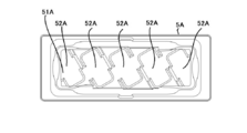
- the packaging container 4 of the second embodiment of the present invention includes a container body 5.
- the packaging container 4 may be provided with at least a container body 5, and may be provided with a lid (not shown).
- the container body 5 has a flat rectangular parallelepiped shape, and more specifically, it has an arch shape in which the vicinity of the middle in the length direction of the rectangular parallelepiped bulges upward.
- the one longitudinal edge side of the container body 5 will be described as the front side.
- the container body 5 has a bottom surface portion 51, a plurality of mounting surfaces 52 in which the bottom surface portion 51 is divided into a square shape, a peripheral wall surface portion 53 rising from the periphery of the bottom surface portion 51, and an outer side from the upper edge portion of the peripheral wall surface portion 53. It is provided with a flange portion 54 overhanging.
- the bottom surface portion 51 has a horizontally long rectangular shape in a plan view, and is provided around the mounting portion 51a and the mounting portion 51a composed of a plurality of mounting surfaces 52 partitioned in a parallel four-sided shape. It is provided with a groove-shaped concave groove portion 51b. The vicinity of the four corners of the concave groove portion 51b is a leg portion 55 that is further recessed in an L-shape in a plan view and protrudes downward.
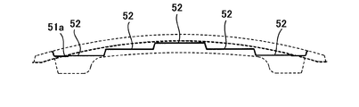
- the mounting surfaces 52 are arranged in five rows in the length direction and one row in the width direction. Each mounting surface 52 is divided into parallel four-sided shapes slightly oblique to the width direction, and as shown in FIG.
- the mounting surface 52 in the middle in the length direction of the container body 5 is the highest. They are arranged in a chevron shape to serve as a position. Further, each mounting surface 52 has a substantially horizontal plane shape so that individual contents such as nigiri sushi can be placed on the mounting surface 52. As shown in FIG. 12 or FIG. 13B, the mounting surface 52 may be provided with a protrusion 52a protruding toward the adjacent mounting surface 52, and by providing the protrusion 52a, adjacent accommodations may be provided. There will be an appropriate gap between the objects, making it easier to pick up with chopsticks.
- the peripheral wall surface portion 53 rises vertically from the peripheral edge of the concave groove portion 51b and surrounds the bottom surface portion 51.
- a flange portion 54 projecting outward is provided on the upper edge portion of the peripheral wall surface portion 53.
- the upper edge portion (upper surface of the flange portion 54) of the peripheral wall surface portion 53 in the longitudinal direction has an arch shape in the side view on the front side, and the container body 5 is viewed from the front side. At the same time, it seems that the center rises in combination with the mounting surfaces 52 arranged in a mountain shape, which makes it easier to attract the attention of the purchaser.
- the outer edge portion of the flange portion 54 is a hanging lower surface portion 54a.
- the packaging container 4 can be manufactured and used in the same manner as the above-mentioned packaging container 1. For example, by placing nigiri sushi or the like on the placing surface 52 and displaying it, it seems that there is a sense of volume, and the purchaser can involuntarily pay attention to it and increase the purchase motivation.
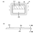
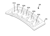
- the packaging container 4A is formed as a concave shape in which the mounting surface 52A is recessed in the bottom surface portion 51A of the container body 5A, and as shown in FIG. 16, the rectangular mounting surface 52A is formed in the width direction of the container body 5A. It is arranged so as to be slightly tilted with respect to the container body, and five rows are provided in the length direction of the container body 5A. Even with such a concave mounting surface 52A, the nigiri sushi and the like on which it is placed appear to have a voluminous feel, and the purchaser can involuntarily gaze at it and increase the purchasing motivation. Further, by making the concave mounting surface 52A, the contained object is less likely to shift and move.
- the configuration of the above embodiment is not mentioned as limiting the present invention, and can be changed as long as the technical purpose is common, and the present invention includes such a change.
Landscapes
- Engineering & Computer Science (AREA)
- Mechanical Engineering (AREA)
- Zoology (AREA)
- General Health & Medical Sciences (AREA)
- Marine Sciences & Fisheries (AREA)
- Toxicology (AREA)
- Health & Medical Sciences (AREA)
- Evolutionary Biology (AREA)
- Life Sciences & Earth Sciences (AREA)
- Ceramic Engineering (AREA)
- Containers Having Bodies Formed In One Piece (AREA)
- Packging For Living Organisms, Food Or Medicinal Products That Are Sensitive To Environmental Conditiond (AREA)
- Details Of Rigid Or Semi-Rigid Containers (AREA)
Priority Applications (3)
| Application Number | Priority Date | Filing Date | Title |
|---|---|---|---|
| JP2022504641A JP7193195B2 (ja) | 2020-07-10 | 2020-07-10 | 包装用容器 |
| PCT/JP2020/027118 WO2022009431A1 (ja) | 2020-07-10 | 2020-07-10 | 包装用容器 |
| CN202080102613.XA CN115867497B (zh) | 2020-07-10 | 2020-07-10 | 包装用容器 |
Applications Claiming Priority (1)
| Application Number | Priority Date | Filing Date | Title |
|---|---|---|---|
| PCT/JP2020/027118 WO2022009431A1 (ja) | 2020-07-10 | 2020-07-10 | 包装用容器 |
Publications (1)
| Publication Number | Publication Date |
|---|---|
| WO2022009431A1 true WO2022009431A1 (ja) | 2022-01-13 |
Family
ID=79553236
Family Applications (1)
| Application Number | Title | Priority Date | Filing Date |
|---|---|---|---|
| PCT/JP2020/027118 Ceased WO2022009431A1 (ja) | 2020-07-10 | 2020-07-10 | 包装用容器 |
Country Status (3)
| Country | Link |
|---|---|
| JP (1) | JP7193195B2 (enExample) |
| CN (1) | CN115867497B (enExample) |
| WO (1) | WO2022009431A1 (enExample) |
Citations (8)
| Publication number | Priority date | Publication date | Assignee | Title |
|---|---|---|---|---|
| JP3062105U (ja) * | 1999-03-11 | 1999-09-28 | 中国パール販売株式会社 | 寿司用包装容器 |
| JP3115032U (ja) * | 2005-07-22 | 2005-11-04 | 日本ザンパック株式会社 | 商品陳列用トレー |
| JP2007269349A (ja) * | 2006-03-31 | 2007-10-18 | Masayuki Nakagawa | 容器 |
| JP2008131923A (ja) * | 2006-11-29 | 2008-06-12 | Shintokyo Kiyari:Kk | 冷凍食品用トレー及び冷凍食品パッケージ |
| JP2012176773A (ja) * | 2011-02-25 | 2012-09-13 | Sekisui Plastics Co Ltd | 鮨用包装容器の容器本体 |
| JP2014118180A (ja) * | 2012-12-17 | 2014-06-30 | Daicel Pack Systems Ltd | 包装容器 |
| JP2018095306A (ja) * | 2016-12-16 | 2018-06-21 | 中央化学株式会社 | 包装用容器 |
| JP6403745B2 (ja) * | 2016-11-28 | 2018-10-10 | 株式会社エフピコ | 寿司用容器 |
Family Cites Families (6)
| Publication number | Priority date | Publication date | Assignee | Title |
|---|---|---|---|---|
| JP2947469B2 (ja) * | 1998-01-14 | 1999-09-13 | 東京ラップ株式会社 | 食品用包装容器の変形防止構造 |
| JP2002095429A (ja) * | 2000-09-20 | 2002-04-02 | Chuo Kagaku Co Ltd | 寿司用包装容器 |
| JP3559017B2 (ja) * | 2001-12-12 | 2004-08-25 | 東京ラップ株式会社 | 包装容器 |
| JP5739133B2 (ja) * | 2010-10-20 | 2015-06-24 | シーピー化成株式会社 | 食品包装容器 |
| JP5568122B2 (ja) * | 2012-11-19 | 2014-08-06 | 株式会社エフピコ | 寿司用容器 |
| JP7199083B2 (ja) * | 2018-08-30 | 2023-01-05 | シーピー化成株式会社 | 包装用容器 |
-
2020
- 2020-07-10 JP JP2022504641A patent/JP7193195B2/ja active Active
- 2020-07-10 CN CN202080102613.XA patent/CN115867497B/zh active Active
- 2020-07-10 WO PCT/JP2020/027118 patent/WO2022009431A1/ja not_active Ceased
Patent Citations (8)
| Publication number | Priority date | Publication date | Assignee | Title |
|---|---|---|---|---|
| JP3062105U (ja) * | 1999-03-11 | 1999-09-28 | 中国パール販売株式会社 | 寿司用包装容器 |
| JP3115032U (ja) * | 2005-07-22 | 2005-11-04 | 日本ザンパック株式会社 | 商品陳列用トレー |
| JP2007269349A (ja) * | 2006-03-31 | 2007-10-18 | Masayuki Nakagawa | 容器 |
| JP2008131923A (ja) * | 2006-11-29 | 2008-06-12 | Shintokyo Kiyari:Kk | 冷凍食品用トレー及び冷凍食品パッケージ |
| JP2012176773A (ja) * | 2011-02-25 | 2012-09-13 | Sekisui Plastics Co Ltd | 鮨用包装容器の容器本体 |
| JP2014118180A (ja) * | 2012-12-17 | 2014-06-30 | Daicel Pack Systems Ltd | 包装容器 |
| JP6403745B2 (ja) * | 2016-11-28 | 2018-10-10 | 株式会社エフピコ | 寿司用容器 |
| JP2018095306A (ja) * | 2016-12-16 | 2018-06-21 | 中央化学株式会社 | 包装用容器 |
Also Published As
| Publication number | Publication date |
|---|---|
| JP7193195B2 (ja) | 2022-12-20 |
| JPWO2022009431A1 (enExample) | 2022-01-13 |
| CN115867497A (zh) | 2023-03-28 |
| CN115867497B (zh) | 2024-10-22 |
Similar Documents
| Publication | Publication Date | Title |
|---|---|---|
| JP7013002B2 (ja) | 包装用容器 | |
| JP2967865B2 (ja) | 透明蓋の食品容器 | |
| WO2022009431A1 (ja) | 包装用容器 | |
| JP7313093B2 (ja) | 包装用容器 | |
| JP5562270B2 (ja) | 包装用容器 | |
| JP2015224040A (ja) | 食品盛り付け用トレー容器 | |
| JP2014051325A (ja) | 包装用容器 | |
| JP7491544B2 (ja) | 包装用容器 | |
| JP2021123392A (ja) | 包装用容器 | |
| JP6962555B2 (ja) | 包装用容器 | |
| JP6966109B2 (ja) | 包装用容器 | |
| JP3221604B2 (ja) | 陳列用包装容器 | |
| JP2008254756A (ja) | 蓋体のフランジ部全体に小突起を形成した包装用容器 | |
| JP7153906B2 (ja) | 包装用容器 | |
| JP7417238B2 (ja) | 包装用容器 | |
| JP7092330B2 (ja) | 包装用容器 | |
| US20210039844A1 (en) | Unitary supplementary packaging systems | |
| JP7153905B2 (ja) | 包装用容器 | |
| JP7288728B1 (ja) | 鮨用包装容器 | |
| JP2022102707A (ja) | 包装用容器の容器本体又は蓋体 | |
| JP6885570B2 (ja) | 包装用容器 | |
| JP2506980Y2 (ja) | 組合せ式容器 | |
| JP4560315B2 (ja) | 包装用容器 | |
| JP7475681B2 (ja) | 包装用容器 | |
| JP5378161B2 (ja) | 蓋付きトレー及び容器用蓋 |
Legal Events
| Date | Code | Title | Description |
|---|---|---|---|
| ENP | Entry into the national phase |
Ref document number: 2022504641 Country of ref document: JP Kind code of ref document: A |
|
| 121 | Ep: the epo has been informed by wipo that ep was designated in this application |
Ref document number: 20944048 Country of ref document: EP Kind code of ref document: A1 |
|
| NENP | Non-entry into the national phase |
Ref country code: DE |
|
| 122 | Ep: pct application non-entry in european phase |
Ref document number: 20944048 Country of ref document: EP Kind code of ref document: A1 |