WO2022004547A1 - 固体電池 - Google Patents
固体電池 Download PDFInfo
- Publication number
- WO2022004547A1 WO2022004547A1 PCT/JP2021/023937 JP2021023937W WO2022004547A1 WO 2022004547 A1 WO2022004547 A1 WO 2022004547A1 JP 2021023937 W JP2021023937 W JP 2021023937W WO 2022004547 A1 WO2022004547 A1 WO 2022004547A1
- Authority
- WO
- WIPO (PCT)
- Prior art keywords
- solid
- state battery
- moisture
- laminate
- electrode layer
- Prior art date
- Legal status (The legal status is an assumption and is not a legal conclusion. Google has not performed a legal analysis and makes no representation as to the accuracy of the status listed.)
- Ceased
Links
Images





Classifications
-
- H—ELECTRICITY
- H01—ELECTRIC ELEMENTS
- H01M—PROCESSES OR MEANS, e.g. BATTERIES, FOR THE DIRECT CONVERSION OF CHEMICAL ENERGY INTO ELECTRICAL ENERGY
- H01M10/00—Secondary cells; Manufacture thereof
- H01M10/05—Accumulators with non-aqueous electrolyte
- H01M10/058—Construction or manufacture
- H01M10/0585—Construction or manufacture of accumulators having only flat construction elements, i.e. flat positive electrodes, flat negative electrodes and flat separators
-
- H—ELECTRICITY
- H01—ELECTRIC ELEMENTS
- H01M—PROCESSES OR MEANS, e.g. BATTERIES, FOR THE DIRECT CONVERSION OF CHEMICAL ENERGY INTO ELECTRICAL ENERGY
- H01M10/00—Secondary cells; Manufacture thereof
- H01M10/05—Accumulators with non-aqueous electrolyte
- H01M10/052—Li-accumulators
-
- H—ELECTRICITY
- H01—ELECTRIC ELEMENTS
- H01M—PROCESSES OR MEANS, e.g. BATTERIES, FOR THE DIRECT CONVERSION OF CHEMICAL ENERGY INTO ELECTRICAL ENERGY
- H01M10/00—Secondary cells; Manufacture thereof
- H01M10/04—Construction or manufacture in general
- H01M10/0436—Small-sized flat cells or batteries for portable equipment
-
- H—ELECTRICITY
- H01—ELECTRIC ELEMENTS
- H01M—PROCESSES OR MEANS, e.g. BATTERIES, FOR THE DIRECT CONVERSION OF CHEMICAL ENERGY INTO ELECTRICAL ENERGY
- H01M10/00—Secondary cells; Manufacture thereof
- H01M10/05—Accumulators with non-aqueous electrolyte
- H01M10/052—Li-accumulators
- H01M10/0525—Rocking-chair batteries, i.e. batteries with lithium insertion or intercalation in both electrodes; Lithium-ion batteries
-
- H—ELECTRICITY
- H01—ELECTRIC ELEMENTS
- H01M—PROCESSES OR MEANS, e.g. BATTERIES, FOR THE DIRECT CONVERSION OF CHEMICAL ENERGY INTO ELECTRICAL ENERGY
- H01M10/00—Secondary cells; Manufacture thereof
- H01M10/05—Accumulators with non-aqueous electrolyte
- H01M10/056—Accumulators with non-aqueous electrolyte characterised by the materials used as electrolytes, e.g. mixed inorganic/organic electrolytes
- H01M10/0561—Accumulators with non-aqueous electrolyte characterised by the materials used as electrolytes, e.g. mixed inorganic/organic electrolytes the electrolyte being constituted of inorganic materials only
- H01M10/0562—Solid materials
-
- H—ELECTRICITY
- H01—ELECTRIC ELEMENTS
- H01M—PROCESSES OR MEANS, e.g. BATTERIES, FOR THE DIRECT CONVERSION OF CHEMICAL ENERGY INTO ELECTRICAL ENERGY
- H01M10/00—Secondary cells; Manufacture thereof
- H01M10/42—Methods or arrangements for servicing or maintenance of secondary cells or secondary half-cells
- H01M10/4235—Safety or regulating additives or arrangements in electrodes, separators or electrolyte
-
- H—ELECTRICITY
- H01—ELECTRIC ELEMENTS
- H01M—PROCESSES OR MEANS, e.g. BATTERIES, FOR THE DIRECT CONVERSION OF CHEMICAL ENERGY INTO ELECTRICAL ENERGY
- H01M10/00—Secondary cells; Manufacture thereof
- H01M10/42—Methods or arrangements for servicing or maintenance of secondary cells or secondary half-cells
- H01M10/425—Structural combination with electronic components, e.g. electronic circuits integrated to the outside of the casing
-
- H—ELECTRICITY
- H01—ELECTRIC ELEMENTS
- H01M—PROCESSES OR MEANS, e.g. BATTERIES, FOR THE DIRECT CONVERSION OF CHEMICAL ENERGY INTO ELECTRICAL ENERGY
- H01M50/00—Constructional details or processes of manufacture of the non-active parts of electrochemical cells other than fuel cells, e.g. hybrid cells
- H01M50/20—Mountings; Secondary casings or frames; Racks, modules or packs; Suspension devices; Shock absorbers; Transport or carrying devices; Holders
- H01M50/233—Mountings; Secondary casings or frames; Racks, modules or packs; Suspension devices; Shock absorbers; Transport or carrying devices; Holders characterised by physical properties of casings or racks, e.g. dimensions
- H01M50/24—Mountings; Secondary casings or frames; Racks, modules or packs; Suspension devices; Shock absorbers; Transport or carrying devices; Holders characterised by physical properties of casings or racks, e.g. dimensions adapted for protecting batteries from their environment, e.g. from corrosion
-
- H—ELECTRICITY
- H01—ELECTRIC ELEMENTS
- H01M—PROCESSES OR MEANS, e.g. BATTERIES, FOR THE DIRECT CONVERSION OF CHEMICAL ENERGY INTO ELECTRICAL ENERGY
- H01M50/00—Constructional details or processes of manufacture of the non-active parts of electrochemical cells other than fuel cells, e.g. hybrid cells
- H01M50/50—Current conducting connections for cells or batteries
- H01M50/543—Terminals
-
- H—ELECTRICITY
- H01—ELECTRIC ELEMENTS
- H01M—PROCESSES OR MEANS, e.g. BATTERIES, FOR THE DIRECT CONVERSION OF CHEMICAL ENERGY INTO ELECTRICAL ENERGY
- H01M50/00—Constructional details or processes of manufacture of the non-active parts of electrochemical cells other than fuel cells, e.g. hybrid cells
- H01M50/50—Current conducting connections for cells or batteries
- H01M50/543—Terminals
- H01M50/547—Terminals characterised by the disposition of the terminals on the cells
- H01M50/55—Terminals characterised by the disposition of the terminals on the cells on the same side of the cell
-
- H—ELECTRICITY
- H01—ELECTRIC ELEMENTS
- H01M—PROCESSES OR MEANS, e.g. BATTERIES, FOR THE DIRECT CONVERSION OF CHEMICAL ENERGY INTO ELECTRICAL ENERGY
- H01M6/00—Primary cells; Manufacture thereof
- H01M6/14—Cells with non-aqueous electrolyte
- H01M6/18—Cells with non-aqueous electrolyte with solid electrolyte
-
- H—ELECTRICITY
- H01—ELECTRIC ELEMENTS
- H01M—PROCESSES OR MEANS, e.g. BATTERIES, FOR THE DIRECT CONVERSION OF CHEMICAL ENERGY INTO ELECTRICAL ENERGY
- H01M2220/00—Batteries for particular applications
- H01M2220/30—Batteries in portable systems, e.g. mobile phone, laptop
-
- H—ELECTRICITY
- H01—ELECTRIC ELEMENTS
- H01M—PROCESSES OR MEANS, e.g. BATTERIES, FOR THE DIRECT CONVERSION OF CHEMICAL ENERGY INTO ELECTRICAL ENERGY
- H01M2300/00—Electrolytes
- H01M2300/0017—Non-aqueous electrolytes
- H01M2300/0065—Solid electrolytes
- H01M2300/0068—Solid electrolytes inorganic
-
- Y—GENERAL TAGGING OF NEW TECHNOLOGICAL DEVELOPMENTS; GENERAL TAGGING OF CROSS-SECTIONAL TECHNOLOGIES SPANNING OVER SEVERAL SECTIONS OF THE IPC; TECHNICAL SUBJECTS COVERED BY FORMER USPC CROSS-REFERENCE ART COLLECTIONS [XRACs] AND DIGESTS
- Y02—TECHNOLOGIES OR APPLICATIONS FOR MITIGATION OR ADAPTATION AGAINST CLIMATE CHANGE
- Y02E—REDUCTION OF GREENHOUSE GAS [GHG] EMISSIONS, RELATED TO ENERGY GENERATION, TRANSMISSION OR DISTRIBUTION
- Y02E60/00—Enabling technologies; Technologies with a potential or indirect contribution to GHG emissions mitigation
- Y02E60/10—Energy storage using batteries
-
- Y—GENERAL TAGGING OF NEW TECHNOLOGICAL DEVELOPMENTS; GENERAL TAGGING OF CROSS-SECTIONAL TECHNOLOGIES SPANNING OVER SEVERAL SECTIONS OF THE IPC; TECHNICAL SUBJECTS COVERED BY FORMER USPC CROSS-REFERENCE ART COLLECTIONS [XRACs] AND DIGESTS
- Y02—TECHNOLOGIES OR APPLICATIONS FOR MITIGATION OR ADAPTATION AGAINST CLIMATE CHANGE
- Y02P—CLIMATE CHANGE MITIGATION TECHNOLOGIES IN THE PRODUCTION OR PROCESSING OF GOODS
- Y02P70/00—Climate change mitigation technologies in the production process for final industrial or consumer products
- Y02P70/50—Manufacturing or production processes characterised by the final manufactured product
Definitions
- the present invention relates to a solid-state battery packaged so as to be suitable for substrate mounting.
- a secondary battery that can be repeatedly charged and discharged have been used for various purposes.
- a secondary battery is used as a power source for electronic devices such as smartphones and notebook computers.
- a liquid electrolyte is generally used as a medium for ion transfer that contributes to charging and discharging. That is, a so-called electrolytic solution is used in the secondary battery.
- electrolytic solution is used in the secondary battery.
- safety is generally required in terms of preventing leakage of the electrolytic solution.
- the organic solvent and the like used in the electrolytic solution are flammable substances, safety is also required in that respect.
- the inventor of the present application noticed that there was a problem to be overcome with the conventional secondary battery, and found that it was necessary to take measures for that. Specifically, the inventor of the present application has found that there are the following problems.
- the solid-state battery will be mounted on a board such as a printed wiring board together with other electronic components and used, and in that case, a battery suitable for mounting is required.
- solid-state batteries need to take necessary measures against moisture in the air. This is because if moisture enters the inside of the solid-state battery, the battery characteristics may be deteriorated.
- Patent Document 1 a positive electrode material and a negative electrode material electrically bonded to a current collector are laminated via a non-fluid electrolyte layer, and a battery element containing an ionic metal component and a hygroscopic agent are combined with a synthetic resin.
- a secondary battery sealed in a manufacturing housing is disclosed.
- Patent Document 1 also discloses that a hygroscopic agent is added to the inside of the housing or to the synthetic resin layer of the housing.
- the secondary battery disclosed in Patent Document 1 may not allow moisture to enter through a gap between the hygroscopic agent and the secondary battery, and cannot be said to be a solid-state battery in which moisture ingress is sufficiently prevented. ..
- a main object of the present invention is to provide a solid-state battery technique for reducing the intrusion of water into a solid-state battery.
- the present invention is a packaged solid-state battery.
- a solid-state battery laminate having a positive electrode layer, a negative electrode layer, and a laminated portion in which a solid electrolyte layer interposed between the positive electrode layer and the negative electrode layer is laminated in the stacking direction.
- a hygroscopic film that comes into contact with at least a part of the solid-state battery laminate and is closely integrated with the solid-state battery laminate. Consists of having.
- the solid-state battery according to the present invention can reduce the intrusion of water into the solid-state battery.
- the present invention is a packaged solid-state battery mainly including a solid-state battery laminate and a moisture-absorbing film.
- the moisture-absorbing film comes into contact with at least a part of the solid-state battery laminate and is closely integrated with the solid-state battery laminate, so that the moisture-absorbing film is between the solid-state battery laminate and the moisture-absorbing film. There is no gap. Since the moisture absorbing film can effectively absorb moisture, it is possible to reduce the invasion of moisture into the solid-state battery.
- the moisture absorbing film and the solid-state battery laminate are closely integrated without any gap, the volume increase of the solid-state battery laminate can be suppressed. Therefore, it is possible to reduce the size of the package without lowering the energy density per volume of the solid-state battery.
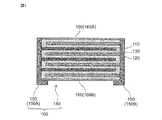
- FIG. 1 is a side sectional view schematically showing the internal structure of the solid-state battery laminate.
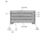
- FIG. 2 is a side sectional view schematically showing another internal configuration of the solid-state battery laminate.
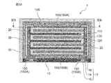
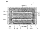
- FIG. 3A is a side sectional view schematically showing the configuration of the solid-state battery according to the embodiment of the present invention.
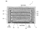
- FIG. 3B is a sectional view (planar sectional view) of IIIB-IIIB of FIG. 3A.
- FIG. 4 is a plan sectional view schematically showing the configuration of a solid-state battery according to another embodiment of the present invention.
- FIG. 5 is a plan sectional view schematically showing the configuration of a solid-state battery according to another embodiment of the present invention.
- FIG. 1 is a side sectional view schematically showing the internal structure of the solid-state battery laminate.
- FIG. 2 is a side sectional view schematically showing another internal configuration of the solid-state battery laminate.
- FIG. 3A is a side sectional view schematically showing the configuration of the solid-
- FIG. 6 is a side sectional view schematically showing the configuration of a solid-state battery according to another embodiment of the present invention.
- FIG. 7 is a side sectional view schematically showing the configuration of a solid-state battery according to another embodiment of the present invention.
- FIG. 8 is a side sectional view schematically showing the configuration of a solid-state battery according to another embodiment of the present invention.
- FIG. 9A is a side sectional view schematically showing the configuration of the solid-state battery according to another embodiment of the present invention (the IXA-IXA sectional view of FIG. 9B).
- 9B is a cross-sectional view taken along the line IXB-IXB of FIG. 9A.
- FIG. 10 is a process sectional view (side sectional view) showing a manufacturing flow of a solid-state battery according to an embodiment of the present invention.
- FIG. 11 is a process sectional view (side sectional view) showing a manufacturing flow of a solid-state battery according to another embodiment of the present invention.
- FIG. 12 is a process sectional view (side sectional view) showing a modified example of the manufacturing flow of the solid-state battery according to the embodiment of the present invention.
- the "packaged solid-state battery” in the present invention means a solid-state battery protected from the external environment in a broad sense, and in a narrow sense, prevents water vapor in the external environment from entering the inside of the solid-state battery. It refers to the solid-state battery that is used.
- the term "water vapor” as used herein refers to water vapor typified by water vapor in the atmosphere, and in a preferred embodiment means water vapor including not only water vapor having a gas form but also liquid water. There is.
- the liquid state water may include dew condensation water in which gaseous water is condensed.
- the solid-state battery of the present invention from which such moisture permeation is prevented is packaged for substrate mounting, and in particular for surface mounting. Therefore, in a preferred embodiment, the battery of the present invention is an SMD (SMD: Surface Mount Device) type battery.
- SMD Surface Mount Device
- the "solid-state battery” as used in the present invention refers to a battery whose components are solid-state in a broad sense, and to an all-solid-state battery whose components (particularly preferably all components) are solid-state in a narrow sense. ..
- the solid-state battery in the present invention is a laminated solid-state battery in which the layers forming the battery building unit are laminated to each other, and preferably such layers are made of a sintered body.
- the "solid-state battery” includes not only a so-called “secondary battery” that can be repeatedly charged and discharged, but also a "primary battery” that can only be discharged.
- a “solid-state battery” is a secondary battery.
- the "secondary battery” is not overly bound by its name and may include, for example, a power storage device.
- the "sintering” referred to in the present invention may be defined as long as the sintering is achieved at least in a part of the "sintering".
- the "side cross section” referred to in the present specification is a form when viewed from a direction substantially perpendicular to the thickness direction based on the stacking direction of each layer constituting the solid-state battery (in short, a surface parallel to the thickness direction). It is based on the form when cut out with.
- the "planar cross section” is a form when viewed from a direction substantially parallel to the thickness direction based on the stacking direction of each layer constituting the solid-state battery (in short, cut out on a plane perpendicular to the thickness direction). It is based on the form of the case).
- the "vertical direction” and “horizontal direction” used directly or indirectly in the present specification correspond to the vertical direction and the horizontal direction in the figure, respectively.
- the same sign or symbol shall indicate the same member / part or the same meaning.
- the vertical downward direction ie, the direction in which gravity acts
- the opposite direction corresponds to the "upward direction”.
- the “top surface” means a surface that is positioned relatively upward among the surfaces constituting the battery, and the “bottom surface” is a relative of the surfaces constituting the battery. It means the surface that is positioned on the lower side. Assuming a typical solid-state battery in which two opposing main surfaces exist, the “top surface” as used herein refers to one of the main surfaces, and the “bottom surface” refers to the main surface. Pointing to the other side of the face.
- the solid-state battery 1 comprises a solid-state battery laminate 100 (see FIGS. 1 and 2), and the solid-state battery laminate 100 includes a positive electrode layer 110, a negative electrode layer 120, and a solid electrolyte 130 at least interposed between them. It has a laminated portion 140 including a battery constituent unit composed of the same, and an external terminal 150 provided on a side surface of the laminated portion.
- the solid-state battery laminate 100 is supported by the support substrate 10 (see FIG. 3A). Further, the solid-state battery 1 may have a coated insulating film 30 that covers the solid-state battery laminate 100 and a coated inorganic film 50 that covers the coated insulating film 30.
- the positive electrode layer 110, the negative electrode layer 120, the solid electrolyte 130, and the like may form a sintered layer.
- the positive electrode layer, the negative electrode layer and the solid electrolyte are each integrally fired, and therefore the laminated portion may form an integrally sintered body.
- the direction in which the positive electrode layer and the negative electrode layer are laminated (vertical direction) is defined as the “stacking direction”, and the direction intersecting the stacking direction is the horizontal direction in which the positive electrode layer and the negative electrode layer extend.
- the positive electrode layer 110 is an electrode layer including at least a positive electrode active material.
- the positive electrode layer may further contain a solid electrolyte.
- the positive electrode layer is composed of a sintered body containing at least positive electrode active material particles and solid electrolyte particles.
- the negative electrode layer 120 is an electrode layer including at least a negative electrode active material.
- the negative electrode layer may further contain a solid electrolyte.
- the negative electrode layer is composed of a sintered body containing at least negative electrode active material particles and solid electrolyte particles.
- the film thickness of the positive electrode layer or the negative electrode layer may be 5 ⁇ m or more and 60 ⁇ m or less, preferably 8 ⁇ m or more and 50 ⁇ m or less. Further, it may be 5 ⁇ m or more and 30 ⁇ m or less.
- the positive electrode active material and the negative electrode active material are substances involved in the transfer of electrons in a solid-state battery. Ions move (conduct) between the positive electrode layer and the negative electrode layer via the solid electrolyte, and electrons are transferred to charge and discharge.
- the positive electrode layer and the negative electrode layer are particularly preferably layers capable of occluding and releasing lithium ions or sodium ions. That is, the solid-state battery is preferably an all-solid-state secondary battery in which lithium ions or sodium ions move between the positive electrode layer and the negative electrode layer via the solid electrolyte to charge and discharge the battery.
- Examples of the positive electrode active material contained in the positive electrode layer include a lithium-containing phosphoric acid compound having a pearcon-type structure, a lithium-containing phosphoric acid compound having an olivine-type structure, a lithium-containing layered oxide, and lithium having a spinel-type structure. At least one selected from the group consisting of oxides and the like can be mentioned.
- the lithium-containing phosphoric acid compound having a pear-con type structure Li 3 V 2 (PO 4 ) 3 and the like can be mentioned.
- Examples of the lithium-containing phosphoric acid compound having an olivine-type structure include Li 3 Fe 2 (PO 4 ) 3 , LiFePO 4 , LiMnPO 4, and the like.
- Examples of the lithium-containing layered oxide include LiCoO 2 , LiCo 1/3 Ni 1/3 Mn 1/3 O 2, and the like.
- Examples of the lithium-containing oxide having a spinel-type structure include LiMn 2 O 4 , LiNi 0.5 Mn 1.5 O 4, and the like.
- the type of the lithium compound is not particularly limited, and may be, for example, a lithium transition metal composite oxide and a lithium transition metal phosphoric acid compound.
- the lithium transition metal composite oxide is a general term for oxides containing lithium and one or more kinds of transition metal elements as constituent elements, and the lithium transition metal phosphoric acid compound is one or more kinds of lithium. It is a general term for phosphoric acid compounds containing the transition metal element of.
- the type of the transition metal element is not particularly limited, and is, for example, cobalt (Co), nickel (Ni), manganese (Mn), iron (Fe), and the like.
- the positive electrode active material capable of occluding and releasing sodium ions includes a sodium-containing phosphoric acid compound having a nacicon-type structure, a sodium-containing phosphoric acid compound having an olivine-type structure, a sodium-containing layered oxide, and sodium having a spinel-type structure. At least one selected from the group consisting of oxides and the like can be mentioned.
- sodium-containing phosphoric acid compounds Na 3 V 2 (PO 4 ) 3 , NaCoFe 2 (PO 4 ) 3 , Na 2 Ni 2 Fe (PO 4 ) 3 , Na 3 Fe 2 (PO 4 ) 3 , Na. 2 FeP 2 O 7 , Na 4 Fe 3 (PO 4 ) 2 (P 2 O 7 ), and at least one selected from the group consisting of NaFeO 2 as the sodium-containing layered oxide.
- the positive electrode active material may be, for example, an oxide, a disulfide, a chalcogenide, a conductive polymer, or the like.
- the oxide may be, for example, titanium oxide, vanadium oxide, manganese dioxide, or the like.
- the disulfide is, for example, titanium disulfide or molybdenum sulfide.
- the chalcogenide may be, for example, niobium selenate or the like.
- the conductive polymer may be, for example, disulfide, polypyrrole, polyaniline, polythiophene, polyparastyrene, polyacetylene, polyacene and the like.
- Examples of the negative electrode active material contained in the negative electrode layer include oxides containing at least one element selected from the group consisting of Ti, Si, Sn, Cr, Fe, Nb and Mo, carbon materials such as graphite, and graphite-lithium. At least one selected from the group consisting of compounds, lithium alloys, lithium-containing phosphoric acid compounds having a pearcon-type structure, lithium-containing phosphoric acid compounds having an olivine-type structure, lithium-containing oxides having a spinel-type structure, and the like. Be done. Examples of lithium alloys include Li-Al and the like.
- lithium-containing phosphoric acid compound having a pear-con type structure examples include Li 3 V 2 (PO 4 ) 3, LiTi 2 (PO 4 ) 3, and the like.
- lithium-containing phosphoric acid compound having an olivine-type structure examples include Li 3 Fe 2 (PO 4 ) 3 , LiCuPO 4, and the like.
- Li 4 Ti 5 O 12 and the like can be mentioned.
- the negative electrode active material capable of occluding and releasing sodium ions includes a sodium-containing phosphoric acid compound having a nacicon-type structure, a sodium-containing phosphoric acid compound having an olivine-type structure, a sodium-containing oxide having a spinel-type structure, and the like. There is at least one selected from the group consisting of.
- the positive electrode layer and / or the negative electrode layer may contain a conductive material.
- the conductive material contained in the positive electrode layer and the negative electrode layer include at least one metal material such as silver, palladium, gold, platinum, aluminum, copper and nickel, and carbon.
- the positive electrode layer and / or the negative electrode layer may contain a sintering aid.
- a sintering aid at least one selected from the group consisting of aluminum oxide, lithium oxide, sodium oxide, potassium oxide, boron oxide, silicon oxide, bismuth oxide and phosphorus oxide can be mentioned.
- the solid electrolyte 130 is a material capable of conducting lithium ions.
- the solid electrolyte 130 which forms a battery constituent unit in a solid-state battery, forms a layer in which lithium ions can be conducted between the positive electrode layer 110 and the negative electrode layer 120.
- Specific examples of the solid electrolyte include a lithium-containing phosphoric acid compound having a pearcon structure, an oxide having a perovskite structure, an oxide having a garnet type or a garnet type similar structure, and an oxide glass ceramics-based lithium ion conductor. Can be mentioned.
- Li 1.2 Al 0.2 Ti 1.8 (PO 4 ) 3 and the like can be mentioned.
- an oxide having a perovskite structure La 0.55 Li 0.35 TiO 3 and the like can be mentioned.
- oxides having a garnet-type or garnet-type similar structure include Li 7 La 3 Zr 2 O 12 and the like.
- oxide glass ceramics-based lithium ion conductor for example, a phosphoric acid compound (LATP) containing lithium, aluminum and titanium as a constituent element, and a phosphoric acid compound (LAGP) containing lithium, aluminum and germanium as constituent elements are used.
- LATP phosphoric acid compound
- LAGP phosphoric acid compound
- the solid electrolyte may be, for example, a glass electrolyte.
- the solid electrolyte layer may contain a sintering aid.
- the sintering aid contained in the solid electrolyte layer may be selected from, for example, the same materials as the sintering aid that can be contained in the positive electrode layer and the negative electrode layer.
- the positive electrode layer 110 and the negative electrode layer 120 may include a positive electrode current collector layer and a negative electrode current collector layer, respectively.
- the positive electrode current collector layer and the negative electrode current collector layer may each have the form of a foil, but from the viewpoint of reducing the manufacturing cost of the solid-state battery and reducing the internal resistance of the solid-state battery by integral firing, the form of the sintered body is adopted. You may have.
- the positive electrode current collector layer and the negative electrode current collector layer have the form of a sintered body, they may be composed of a sintered body containing a conductive material and a sintering aid.
- the conductive material contained in the positive electrode current collector layer and the negative electrode current collector layer may be selected from, for example, the same materials as the conductive materials that can be contained in the positive electrode layer and the negative electrode layer.
- the sintering aid contained in the positive electrode current collector layer and the negative electrode current collector layer may be selected from, for example, the same materials as the sintering aid that can be contained in the positive electrode layer and the negative electrode layer. It should be noted that the positive electrode collector layer and the negative electrode current collector layer are not essential in the solid-state battery, and a solid-state battery in which such a positive electrode current collector layer and the negative electrode current collector layer are not provided is also conceivable. That is, the solid-state battery in the present invention may be a solid-state battery without a current collector layer.
- a pair of external terminals 150 are provided on the side surface of the laminated portion 140 located in the direction intersecting the stacking direction.
- an external terminal may be provided from the side surface to the bottom surface of the laminated portion 140.
- an external terminal 150A on the positive electrode side connected to the positive electrode layer 110 and an external terminal 150B on the negative electrode side connected to the negative electrode layer 120 are provided, and the external terminal 150A on the positive electrode side is one. It may be formed on the side surface (left side in the illustrated example), and the external terminal 150B on the negative electrode side may be provided so as to face the external terminal 150A on the positive electrode side (right side in the illustrated example).
- a pair of external terminals 150 include a material having a high conductivity.
- the specific material of the external terminal is not particularly limited, but may include at least one selected from the group consisting of silver, gold, platinum, aluminum, copper, tin and nickel.
- An inactive substance portion 170 may be provided between the positive electrode layer 110 and the external terminal 150B on the negative electrode side and between the negative electrode layer 120 and the external terminal 150A on the positive electrode side (see FIG. 2).
- the inactive substance unit 170 is provided to insulate between the positive electrode layer 110 and the external terminal 150B on the negative electrode side, and between the negative electrode layer 120 and the external terminal 150A on the positive electrode side. That is, it is preferable that the non-active substance portion has at least electron insulating properties.
- a material conventionally used as an "inactive substance" of a solid-state battery may be used, or may be composed of a resin material, a glass material and / or a ceramic material or the like.
- the ceramic material includes at least one selected from the group consisting of aluminum oxide, boron nitride, silicon dioxide, silicon nitride, zirconium oxide, aluminum nitride, silicon carbide and barium titanate. be able to.
- the inactive substance portion may also be referred to as a "margin portion” or a "negative portion" because of its form.
- An insulating outermost layer 160 may be provided on the outermost side of the laminated portion 140.
- the insulating outermost layer 160 can generally be formed on the outermost side of the laminated portion 140 and is for electrically, physically and / or chemically protecting the solid-state battery laminate.
- the insulating outermost layer 160 includes an insulating outermost layer 160A on the top surface side and an insulating outermost layer 160B on the bottom surface side of the solid-state battery laminate 100.
- the material constituting the outermost layer of insulation is preferably excellent in insulation, durability and / or moisture resistance, and is environmentally safe, and includes, for example, a resin material, a glass material and / or a ceramic material. It may be there.
- the outermost insulating layer since the outermost insulating layer is manufactured by integral firing, it may have the form of a sintered body, and the sintered body containing a sintering aid that can be contained in the positive electrode layer and the negative electrode layer described above (for example, It may be composed of silicon oxide).
- the top surface and the bottom surface of the solid-state battery laminate may be the laminated portion 140 without providing the insulating outermost layer 160.
- the solid-state battery may be provided with a coated insulating film 30 provided so as to cover at least the solid-state battery laminate 100. As shown in FIGS. 3A and 3B, the solid-state battery laminate 100 provided on the support substrate 10 is largely wrapped by the coated insulating film 30 as a whole.
- the coated insulating film 30 preferably corresponds to a resin film. That is, it is preferable that the covering insulating film 30 contains a resin material. As can be seen from the embodiments shown in FIGS. 3A and 3B, this means that the solid-state battery laminate 100 provided on the support substrate 10 is sealed with the resin material of the coating insulating film 30.
- the coated insulating film 30 made of such a resin material, in combination with the coated inorganic film 50, preferably contributes to the reduction of moisture intrusion.
- the material of the covering insulating film may be any kind as long as it exhibits insulating properties.
- the resin may be either a thermosetting resin or a thermoplastic resin.
- examples of the specific resin material of the coating insulating film include epoxy-based resin, silicone-based resin, and / or liquid crystal polymer.
- the thickness of the coating insulating film may be 30 ⁇ m or more and 1000 ⁇ m or less, for example, 50 ⁇ m or more and 300 ⁇ m or less.
- the coated insulating film is not essential for the solid-state battery, and a solid-state battery without the coated insulating film can be considered.
- the solid-state battery may be provided with a coated inorganic film 50 that covers the coated insulating film 30. As shown in FIGS. 3A and 3B, since the coated inorganic film 50 is positioned on the coated insulating film, it has a form of largely enclosing the solid-state battery laminate on the support substrate together with the coated insulating film. ing.
- the coated inorganic film preferably has a thin film form.
- the material of the coated inorganic film is not particularly limited as long as it contributes to the inorganic film having a thin film form, and may be metal, glass, oxide ceramics, or a mixture thereof.
- the coated inorganic film comprises a metallic component. That is, the coated inorganic film is preferably a metal thin film.
- the thickness of such a coated inorganic film may be 0.1 ⁇ m or more and 100 ⁇ m or less, for example, 1 ⁇ m or more and 50 ⁇ m or less.
- the coated inorganic film 50 may be a dry plating film, particularly if it depends on the manufacturing method.
- a dry plating film is a film obtained by a vapor phase method such as physical vapor deposition (PVD) or chemical vapor deposition (CVD), and has a very small thickness on the order of nano or micron. is doing.
- PVD physical vapor deposition
- CVD chemical vapor deposition
- Such a thin dry plating film contributes to more compact packaging.
- the dry plating film is, for example, aluminum (Al), nickel (Ni), palladium (Pd), silver (Ag), tin (Sn), gold (Au), copper (Cu), titanium (Ti), platinum (Pt). ), Silicon / silicon (Si), at least one metal component / semi-metal component selected from the group consisting of SUS and the like, an inorganic oxide and / or a glass component and the like.
- a dry plating film composed of such components is chemically and / or thermally stable, resulting in a solid-state battery having excellent chemical resistance, weather resistance and / or heat resistance, and having further improved long-term reliability. Can be done.
- the coated inorganic film is not indispensable, and a solid-state battery in which the coated inorganic film is not provided is also conceivable.
- the support substrate 10 is a substrate provided so as to support the solid-state battery laminate 100.
- a support substrate is located on one side of the main surface of the solid-state battery for "support”. Further, since it is a "substrate", it preferably has a thin plate-like form as a whole.
- the support substrate may be, for example, a resin substrate or a ceramic substrate, and a substrate having water resistance is preferable.
- the support substrate is a ceramic substrate. That is, the support substrate contains ceramic, which occupies the base material component of the substrate.
- a support substrate made of ceramic is a preferable substrate in terms of heat resistance in substrate mounting as well as contributing to prevention of water vapor permeation.
- Such a ceramic substrate can be obtained by firing, for example, by firing a green sheet laminate.
- the ceramic substrate may be, for example, an LTCC substrate (LTCC: LowTemperature Co-firedCeramics) or an HTCC substrate (HTCC: HighTemperatureCo-firedCeramic).
- the thickness of the support substrate may be 20 ⁇ m or more and 1000 ⁇ m or less, for example, 100 ⁇ m or more and 300 ⁇ m or less.
- the support substrate also functions as a terminal substrate for the solid-state battery laminate. That is, a solid-state battery packaged in such a form that a substrate is interposed can be mounted on another secondary substrate such as a printed wiring board. For example, a solid-state battery can be surface-mounted via a support substrate through solder reflow or the like. From this, it can be said that the packaged solid-state battery is an SMD type battery.
- the terminal board is made of a ceramic board
- the solid-state battery can be an SMD type battery having high heat resistance and can be solder-mounted.
- the support substrate of a preferred embodiment is provided with wiring for electrically connecting the upper and lower surfaces of the substrate, and is a terminal substrate for the external terminal of the packaged solid-state battery.
- the wiring 17 on the terminal board is not particularly limited and may have any form as long as it contributes to the electrical connection between the upper surface and the lower surface of the board. Since it contributes to electrical connection, it can be said that the wiring 17 on the terminal board is a conductive portion of the board.
- the conductive portion of such a substrate may have a form such as a wiring layer, vias and / or lands.
- the support substrate 10 is provided with vias 14 and / or lands 16.
- the term "via” as used herein refers to a member for electrically connecting the vertical direction of the support substrate, that is, the thickness direction of the substrate, and for example, a filled via is preferable, and an inner via may be used. ..
- connection portion refers to a terminal portion / connection portion (preferably a terminal portion connected to a via) for electrical connection provided on the upper main surface and / or the lower main surface of the support substrate. -It points to a connection part), and may be, for example, a corner land or a round land.
- the solid-state battery of the present invention further includes a moisture absorbing film 20 in addition to the basic configuration of the solid-state battery described above (see FIGS. 3A and 3B).
- the moisture absorbing film 20 absorbs moisture contained in the solid-state battery, is in contact with at least a part of the solid-state battery laminate 100, and is closely integrated with the solid-state battery laminate 100.
- "in contact with at least a part and closely integrated" in the present specification means a state in which they are in close contact with each other and integrated with each other without substantially having a gap.
- the moisture absorbing film 20 absorbs moisture with respect to at least one material selected from the group consisting of aluminum oxide, lithium oxide, sodium oxide, potassium oxide, boron oxide, silicon oxide, bismuth oxide and phosphorus oxide. It is composed of a material having a hygroscopic effect, and is formed into a film by kneading these materials with, for example, a binder resin. That is, in one preferred embodiment, the hygroscopic film contains a material having a hygroscopic effect and a binder resin.
- the material having a hygroscopic effect of absorbing moisture include at least one selected from the group consisting of synthetic zeolite, silica gel, phosphorus pentoxide, barium oxide, calcium oxide and an organic metal structure.
- the hygroscopic membrane containing synthetic zeolite is a material that has good temperature resistance and does not deliquesce even when the synthetic zeolite generates heat due to the operation of the solid-state battery and the temperature of the synthetic zeolite becomes high, and the adsorption rate per unit weight is high. It is suitable because it is good.
- the binder resin include an inorganic binder and / or a resin binder.
- the inorganic binder a glass binder can be mentioned. That is, the hygroscopic film may contain a material having a hygroscopic effect and a glass binder.
- the thickness of the moisture absorbing film may be 1 ⁇ m or more and 50 ⁇ m or less from the viewpoint of preventing the volume increase of the solid-state battery, and is preferably 5 ⁇ m or more and 30 ⁇ m or less or 5 ⁇ m or more and 15 ⁇ m or less. Further, the thickness of the hygroscopic film may be uniform or non-uniform. Further, although the moisture absorbing film shows the embodiment of the monolayer film in the embodiments of FIGS. 3A and 3B, the hygroscopic film may be a plurality of films having two or more layers.
- the content of synthetic zeolite or silica gel, which is a preferable material, in the hygroscopic membrane 20 is preferably 1% by volume or more and 85% by volume or less based on the entire hygroscopic membrane, which will be described later. It should be noted that the reference time in the overall hygroscopic film standard may be the time when the solid-state battery is completed.
- the moisture absorbing film 20 is covered so as to be in contact with a pair of external terminals 150 provided opposite to each other in the solid-state battery laminate and to be closely integrated with the external terminals on the side surface. 3A and 3B).
- the "side surface of the solid-state battery laminate" referred to in the present specification is, for example, the "top surface” defined above among the six surfaces constituting the battery having a substantially hexahedral shape in FIGS.
- the solid-state battery laminate is not limited to a substantially hexahedron shape, and may be, for example, a cylindrical shape. In the case of a cylindrical shape, the outer periphery is perpendicular to the “top surface” and the “bottom surface”. Cover the surface.
- the moisture absorbing film 20 and the external terminal 150 of the solid-state battery laminate 100 are closely integrated and have no gap, and the moisture absorbing film 20 absorbs moisture. Further, in the solid-state battery of the present invention, by covering the side surface located in the direction intersecting the stacking direction, which is a place where deterioration is likely to occur when moisture invades, with a moisture absorbing film, the moisture is effectively absorbed and the solid-state battery is laminated. It is possible to reduce the invasion of water into the inside of the body.
- the moisture absorbing film 20 is provided so as to extend from the side surface of the external terminal 150 to the top surface which is the outermost insulating layer surface of the laminated portion 140 in the side sectional view of the solid-state battery.
- the hygroscopic film has a form of bending in a side sectional view.
- the moisture absorbing film 20 covers the interface between the external terminal 150 and the laminated portion 140 in a side sectional view of the solid-state battery.
- the volume increase of the solid-state battery can be suppressed by setting the thickness of the moisture-absorbing film 20 in the solid-state battery to about 1 ⁇ m or more and 50 ⁇ m or less. Therefore, it is possible to suppress a decrease in the energy density per volume and to reduce the size of the package.
- FIG. 4 is a plan sectional view schematically showing the configuration of a solid-state battery according to another embodiment of the present invention.
- the moisture absorbing film 20 may be covered so as to be in close contact with and closely integrated with the side surface of the laminated portion 140 together with the external terminal 150. According to such an embodiment, since the moisture absorbing film is provided over the entire side surface of the solid-state battery laminate 100, it is possible to more effectively reduce the intrusion of moisture into the solid-state battery laminate.
- the moisture absorbing film is provided over the entire four side surfaces of the solid-state battery laminate.
- the inside of the solid-state battery laminate is provided. You may reduce the invading moisture.
- FIG. 5 is a plan sectional view schematically showing the configuration of a solid-state battery according to another embodiment of the present invention.
- the moisture absorbing film 20 may be coated so as to be in close contact with and closely integrated with the side surface of the laminated portion 140 of the solid-state battery laminate excluding the external terminal 150. Even in such an embodiment, since most of the side surfaces of the solid-state battery laminate are covered with the moisture-absorbing film 20, it is possible to reduce the intrusion of moisture into the solid-state battery laminate.
- FIG. 6 is a side sectional view schematically showing the configuration of a solid-state battery according to another embodiment of the present invention. Even if the moisture absorbing film 20 is covered so as to be in contact with the entire side surface of the solid-state battery laminate 100 as well as the insulating outermost layer surface (top surface and bottom surface) of the insulating outermost layer 160 of the solid-state battery laminate 100 so as to be closely integrated. good. More specifically, the entire surface of the solid-state battery laminate 100 is covered with the moisture absorbing film 20. According to such an embodiment, in addition to the intrusion of moisture from the side surface of the solid-state battery laminate 100, it is possible to suppress the unexpected intrusion of moisture from the stacking direction (vertical direction) of the solid-state battery laminate 100. ..
- FIG. 7 is a side sectional view schematically showing the configuration of a solid-state battery according to another embodiment of the present invention.
- the moisture absorbing film 20 may be coated so as to be in contact with and closely integrated with the insulating outermost layer surface (top surface and bottom surface) of the insulating outermost layer 160 of the laminated portion 140 in the solid-state battery laminate. That is, in this embodiment, the moisture absorbing film is not provided on the side surface of the solid-state battery laminate. Even with such an embodiment, it is possible to reduce the unexpected intrusion of moisture from the stacking direction (vertical direction).
- FIG. 8 is a side sectional view schematically showing the configuration of a solid-state battery according to another embodiment of the present invention.
- the moisture-absorbing film 20 is in close contact with the support surface of the support substrate 10 that supports the solid-state battery laminate 100 as well as the entire insulation outermost layer surface (top surface and bottom surface) and the side surface of the insulation outermost layer 160 of the solid-state battery laminate 100. It may be coated so as to be integrated. According to such an embodiment, in addition to the intrusion of moisture from the entire surface of the solid-state battery laminate 100, the moisture can be absorbed by the support surface of the support substrate before the moisture reaches the solid-state battery laminate 100. , The intrusion of water into the solid-state battery can be further reduced.
- FIG. 9A is a side sectional view schematically showing the configuration of the solid-state battery according to another embodiment of the present invention (IXA-IXA sectional view of FIG. 9B), and FIG. 9B is an IXB-IXB sectional view of FIG. 9A.
- the solid-state battery laminate may be supported by the support substrate so that the stacking direction of the laminated portion 140 and the support surface of the support substrate 10 are parallel to each other (see FIG. 9B).
- the present embodiment shows an embodiment in which the entire surface of the laminated portion 140 is covered with the moisture absorbing film 20 (see FIG.
- the moisture absorbing film may be provided so as to cover at least the interface between the laminated portion and the external terminal. good. According to such a configuration, the interface between the laminated portion and the external terminal is covered with a moisture absorbing film, and moisture is absorbed by the moisture absorbing film, so that the intrusion of moisture into the solid-state battery can be reduced. Further, according to this embodiment, even if expansion occurs in the stacking direction due to charging / discharging or the like, deformation of the support substrate due to expansion can be reduced.
- parallel as used herein is not limited to a state of being completely parallel, but also includes a state of being substantially parallel.
- the object of the present invention is obtained by preparing a solid-state battery containing a positive electrode layer, a negative electrode layer, and a battery building unit having a solid electrolyte between the electrodes, and then packaging the solid-state battery. be able to.
- the solid-state battery of the present invention is manufactured by manufacturing the laminated portion 140 (FIG. 10 (a)), forming the external terminal 150 (FIG. 10 (b)), and forming the moisture absorbing film 20 (FIG. 10 (a)). c)), fixing to the support substrate 10 (FIG. 10 (d)), and forming the coated insulating film 30 and the coated inorganic film 50 (FIG. 10 (e)).
- the explanation will be given step by step.
- the laminated portion 140 can be manufactured by a printing method such as a screen printing method, a green sheet method using a green sheet, or a composite method thereof. That is, the laminated portion itself may be manufactured according to a conventional solid-state battery manufacturing method (therefore, the solid electrolyte, the organic binder, the solvent, any additive, the positive electrode active material, the negative electrode active material, etc. described below, etc. As the raw material, those used in the manufacture of known solid-state batteries may be used).
- a slurry by mixing a solid electrolyte, an organic binder, a solvent and any additive. Then, a sheet having a thickness of about 10 ⁇ m after firing is obtained by sheet molding from the prepared slurry.
- a positive electrode active material, a solid electrolyte, a conductive material, an organic binder, a solvent and any additive are mixed to prepare a positive electrode paste.
- the negative electrode active material, the solid electrolyte, the conductive material, the organic binder, the solvent and any additive are mixed to prepare a paste for the negative electrode. Then, the positive electrode paste is printed on the sheet, and the current collector layer and / or the negative layer is printed as needed.
- the negative electrode paste is printed on the sheet, and the current collector layer and / or the negative layer is printed as needed. Then, the sheet on which the positive electrode paste is printed and the sheet on which the negative electrode paste is printed are alternately laminated to obtain a laminate.
- the outermost insulating layer (uppermost layer and / or lowest layer) of the laminated body it may be an electrolyte layer, an insulating layer, or an electrode layer.
- laminated portion 140 After crimping and integrating the laminate, cut it to the specified size. The obtained cut laminate is subjected to degreasing and firing. As a result, a sintered laminated body (laminated portion 140) is obtained. The laminate may be subjected to degreasing and firing before cutting, and then cut.
- the external terminal on the positive electrode side can be formed by applying a conductive paste to the exposed side surface of the positive electrode in the laminated portion 140.
- the external terminal on the negative electrode side can be formed by applying a conductive paste to the exposed side surface of the negative electrode in the laminated portion 140. If the external terminals on the positive electrode side and the negative electrode side are provided so as to extend to the lower surface of the sintered laminate, they can be connected to the mounting land in a small area in the next step (more specifically, the lower surface of the sintered laminate).
- the external terminal provided so as to extend to has a folded portion on the lower surface thereof, and such a folded portion can be electrically connected to the mounting land).
- the component of the external terminal may be selected from at least one selected from silver, gold, platinum, aluminum, copper, tin and nickel.
- the external terminals on the positive electrode side and the negative electrode side are not limited to being formed after sintering the laminated body, but may be formed before firing and subjected to simultaneous sintering.
- a moisture absorbing film 20 is formed on the solid-state battery laminate 100.
- at least one powder selected from the group consisting of synthetic zeolite, silica gel, phosphorus pentoxide, barium oxide, calcium oxide, and an organic metal structure is mixed with a binder resin together with a solvent to prepare a paste solution.
- a desired location where the moisture absorbing film is formed for example, the side surface where the external terminal of the solid-state battery laminate is formed, the side surface where the external terminal of the solid-state battery laminate is not formed, the insulating outermost layer of the solid-state battery laminate).
- a moisture absorbing film is formed by dipping the paste solution.
- the film thickness of the hygroscopic film is adjusted by the number of dips. Further, when the moisture absorbing film is formed on the entire surface of the solid-state battery laminate, the solid-state battery laminate may be completely dipped in the paste solution (see FIG. 11 (c)).
- the formation of the hygroscopic film and the subsequent steps are preferably performed in a dry atmosphere in order to prevent the hygroscopic film from absorbing moisture during the steps.
- a method of forming a hygroscopic film by dipping it in a paste solution has been described, but the method is not limited to this method, and for example, a paste solution may be spray-coated to form a hygroscopic film. good.
- a support board provided with vias and / or lands is used so that it can be surface-mounted on a secondary board. For example, it can be obtained by laminating and firing a plurality of green sheets. This is especially true when the support substrate is a ceramic substrate.
- the support substrate can be prepared, for example, according to the preparation of the LTCC substrate.
- a method of forming holes for example, a method of forming holes (diameter size: about 50 ⁇ m or more and 200 ⁇ m or less) by punch press or carbon dioxide laser, and filling the holes with a conductive paste material, or printing. Manufactured by a method using the method.
- the solid-state battery laminate 100 is arranged on the support substrate 10 so that the conductive portion of the support substrate 10 and the external terminal 150 of the solid-state battery laminate 100 are electrically connected to each other. .. Then, the conductive paste may be applied onto the support substrate 10 so that the conductive portion of the support substrate 10 and the external terminal 150 of the solid-state battery laminate 100 are electrically connected to each other.
- the conductive paste in addition to the Ag conductive paste, a conductive paste such as a nanopaste, an alloy paste or a brazing material, which does not require cleaning of flux or the like after formation, can be used.
- the coated insulating film 30 is formed so as to cover the solid-state battery laminate 100 on the support substrate 10. Therefore, the raw material of the coated insulating film 30 is provided so that the solid-state battery laminate 100 on the support substrate 10 is entirely covered.
- the coated insulating film 30 is made of a resin material, a resin precursor is provided on the support substrate 10 and subjected to curing or the like to form the coated insulating film 30.
- the coated insulating film 30 may be formed by applying pressure to the mold.
- the coated insulating film 30 that seals the solid-state battery laminate 100 on the support substrate 10 may be molded through a compression mold.
- the form of the raw material of the coating insulating film may be granular, or the type may be thermoplastic. It should be noted that such molding is not limited to mold molding, and may be performed through polishing, laser processing, and / or chemical processing.
- the coated insulating film 30 made of a resin material when the coated insulating film 30 made of a resin material is cured, the coated insulating film 30 shrinks, and the stress generated by the shrinkage may have some influence on the solid-state battery laminate 100.
- the moisture absorbing film 20 is formed on the solid-state battery laminate 100 before the covering insulating film 30 is formed. Therefore, even if a shrinkage stress occurs when the covering insulating film 30 is cured, the stress can be relaxed by the moisture absorbing film 20 and the influence on the solid-state battery laminate 100 can be reduced.
- the coated inorganic film 50 may be subjected to dry plating, for example, and a dry plated film may be used as the coated inorganic film. More specifically, dry plating is performed to form the coated inorganic film 50 on an exposed surface other than the bottom surface of the coated precursor (that is, other than the bottom surface of the support substrate). In one preferred embodiment, sputtering is performed to form a sputter film on an exposed outer surface other than the bottom surface of the coating precursor.
- the packaged solid-state battery according to the present invention can be finally obtained.
- the hygroscopic film may be formed after being fixed to the support substrate.
- a solid-state battery having a moisture-absorbing film 20 may be manufactured by dipping it in a paste solution in a state where the solid-state battery laminate 100 is fixed to the support substrate 10. According to such a manufacturing method, since the moisture absorbing film is formed on the support substrate together with the solid-state battery laminate, it is possible to more reliably reduce the intrusion of moisture into the solid-state battery.
- Example 1 -Solid-state battery Solid-state battery shown in FIGS. 3A and 3B-Hygroscopic material type: Synthetic zeolite (Tosoh Corporation Zeoram (registered trademark) A-5) -Volume fraction of hygroscopic material: 1% by weight based on the entire hygroscopic membrane
- Example 2 -Solid-state battery Solid-state battery shown in FIGS. 3A and 3B-Moisture-absorbing material type: Synthetic zeolite-Volume fraction of moisture-absorbing material: 20% by weight based on the entire moisture-absorbing film
- Example 3 -Solid-state battery Solid-state battery shown in FIGS. 3A and 3B-Moisture-absorbing material type: Synthetic zeolite-Volume fraction of moisture-absorbing material: 40% by weight based on the entire moisture-absorbing film
- Example 4 Solid-state battery shown in FIGS. 3A and 3B-Moisture-absorbing material type: Synthetic zeolite-Volume fraction of moisture-absorbing material: 80% by weight based on the entire moisture-absorbing film
- Example 5 Solid-state battery shown in Fig. 3A and Fig. 3B-Moisture-absorbing material type: Silica gel (Toyota Kako Co., Ltd. Toyota silica gel type A) -Volume fraction of hygroscopic material: 40% by weight based on the entire hygroscopic membrane
- Example 6 -Solid-state battery Solid-state battery shown in Fig. 4-Moisture-absorbing material type: Synthetic zeolite-Volume fraction of moisture-absorbing material: 40% by weight based on the entire moisture-absorbing film
- Example 7 Solid-state battery shown in Fig.
- 5-Moisture-absorbing material type Synthetic zeolite-Volume fraction of moisture-absorbing material: 40% by weight based on the entire moisture-absorbing film
- Example 8 -Solid-state battery Solid-state battery shown in Fig. 6-Moisture-absorbing material type: Synthetic zeolite-Volume fraction of moisture-absorbing material: 40% by weight based on the entire moisture-absorbing film
- Example 9 Solid-state battery shown in Fig. 7-Moisture-absorbing material type: Synthetic zeolite-Volume fraction of moisture-absorbing material: 40% by weight based on the entire moisture-absorbing film
- Example 10 -Solid-state battery Solid-state battery shown in Fig. 8-Moisture-absorbing material type: Synthetic zeolite-Volume fraction of moisture-absorbing material: 40% by weight based on the entire moisture-absorbing film
- Comparative example -Solid-state battery A solid-state battery that does not have a conventionally known moisture-absorbing film.
- the solid-state battery on which the coated inorganic film 50 was not formed was placed at 23 ° C. in an environment of 20% relative humidity (dew point of about 0 ° C.). It was stored for a week, and the rate of change between the change in discharge capacity after storage and the change in discharge capacity before storage was confirmed. For the calculation of the change in discharge capacity, a method of confirming the change in discharge capacity when the charge / discharge device was charged to 4.2 V and then discharged to 2.0 V was adopted. Further, in order to carry out the test in a state where moisture easily enters the solid-state battery, the above-mentioned verification test was performed on the solid-state battery not provided with the coated inorganic film. The verification test results are shown in Table 1 below.
- the rate of change in the discharge capacity of the solid-state batteries of Examples 1 to 10 was confirmed, it was better than the rate of change in the discharge capacity of the solid-state battery of the comparative example.
- the result was that the content was preferably 1% by volume or more and 85% by volume or less based on the entire moisture-absorbing film.
- the rate of change in the discharge capacity of the solid-state battery of Example 10 was small and very good. Since the moisture-absorbing film contains a resin binder or the like, the upper limit of the content of the moisture-absorbing material is set to 85% by volume, but if it can be formed as a film, the content of the resin binder or the like may be reduced. The content of the moisture absorbing material may be 85% by volume or more.
- the solid-state battery is not limited to a substantially hexahedral shape, and may be a polyhedral shape, a cylindrical shape, or a spherical shape.
- the packaged solid-state battery of the present invention can be used in various fields where battery use or storage is expected.
- the packaged solid-state battery of the present invention can be used in the field of electronics mounting.
- the fields of electricity, information, and communication in which mobile devices are used for example, mobile phones, smartphones, laptop computers and digital cameras, activity meters, arm computers, electronic paper, RFID tags, card-type electronic money, smart watches, etc.
- Electric / electronic equipment field including small electronic equipment or mobile equipment field
- home / small industrial use for example, electric tool, golf cart, home / nursing / industrial robot field
- large industrial use for example
- Forklifts, elevators, bay port cranes transportation systems (eg hybrid cars, electric cars, buses, trains, electrically assisted bicycles, electric motorcycles, etc.), power system applications (eg, various power generations, road conditioners) , Smart grid, general home-installed power storage system, etc.), as well as medical use (medical equipment field such as earphone hearing aid), pharmaceutical use (dose management system
- Solid-state battery 10 Support substrate 14 Via 16 Land 17 Wiring 20 Moisture-absorbing film 30 Coated insulating film 50 Coated inorganic film 100 Solid-state battery laminate 110 Positive electrode layer 120 Negative electrode layer 130 Solid electrolyte 140 Laminated part 150 External terminal 150A External terminal 150B on the positive electrode side External terminal on the negative electrode side 160 Insulation outermost layer 160A Insulation outermost layer top surface 160B Insulation outermost layer bottom surface 170 Inactive substance part
Landscapes
- Chemical & Material Sciences (AREA)
- Engineering & Computer Science (AREA)
- Chemical Kinetics & Catalysis (AREA)
- Electrochemistry (AREA)
- General Chemical & Material Sciences (AREA)
- Manufacturing & Machinery (AREA)
- Microelectronics & Electronic Packaging (AREA)
- Materials Engineering (AREA)
- Physics & Mathematics (AREA)
- Condensed Matter Physics & Semiconductors (AREA)
- General Physics & Mathematics (AREA)
- Inorganic Chemistry (AREA)
- Secondary Cells (AREA)
- Sealing Battery Cases Or Jackets (AREA)
- Cell Separators (AREA)
- Connection Of Batteries Or Terminals (AREA)
Abstract
固体電池に水分が侵入することを低減する固体電池の技術を提供する。パッケージ化された固体電池1であって、正極層110、負極層120、および正極層110と負極層120との間に介在する固体電解質130を有する積層部140を備えた固体電池積層体100と、固体電池積層体100の少なくとも一部と接触し、固体電池積層体100と密接一体化される吸湿膜20と、を有して成る。
Description
本発明は、基板実装に適するようにパッケージ化された固体電池に関する。
従前より、繰り返しの充放電が可能な二次電池が様々な用途に用いられている。例えば、二次電池は、スマートフォンおよびノートパソコン等の電子機器の電源として用いられている。
当該二次電池においては、充放電に寄与するイオン移動のための媒体として液体の電解質が一般に使用されている。つまり、いわゆる電解液が二次電池に用いられている。しかしながら、そのような二次電池においては、電解液の漏出防止点で安全性が一般に求められる。また、電解液に用いられる有機溶媒等は可燃性物質ゆえ、その点でも安全性が求められる。
そこで、電解液に代えて、固体電解質を用いて構成された固体電池について研究が進められている。
本願発明者は、従前の二次電池では克服すべき課題があることに気付き、そのための対策を取る必要性を見出した。具体的には以下の課題があることを本願発明者は見出した。
固体電池は、他の電子部品と共にプリント配線板などの基板上に実装されて使用されることが考えられ、その場合には実装に適したものが求められる。その一方、固体電池は、空気中の水分に対して必要な措置を確実に講じておく必要がある。固体電池の内部に水分が進入すると、電池特性の劣化が引き起こされたりする虞があるからである。
ここで、特許文献1には、集電体に電気的に結合した正極材と負極材が非流動性電解質層を介して積層され、イオン性金属成分を含有する電池要素と吸湿剤を合成樹脂製ハウジングで封止した二次電池が開示されている。また、特許文献1には、ハウジング内あるいはハウジングの合成樹脂層に吸湿剤が添加される点も開示されている。
しかしながら、特許文献1に開示された二次電池は、吸湿剤と二次電池との間の隙間から水分が進入する虞があり、水分進入が十分に防止された固体電池であるとは言い難い。
本発明は、かかる課題に鑑みて為されたものである。即ち、本発明の主たる目的は、固体電池に水分が侵入することを低減する固体電池の技術を提供することである。
本願発明者は、従来技術の延長線上で対応するのではなく、新たな方向で対処することによって上記課題の解決を試みた。その結果、上記主たる目的が達成された固体電池の発明に至った。
本発明は、パッケージ化された固体電池であって、
正極層、負極層、および該正極層と該負極層との間に介在する固体電解質層を積層方向に積層させた積層部を備えた固体電池積層体と、
前記固体電池積層体の少なくとも一部と接触し、該固体電池積層体と密接一体化される吸湿膜と、
を有して成る。
正極層、負極層、および該正極層と該負極層との間に介在する固体電解質層を積層方向に積層させた積層部を備えた固体電池積層体と、
前記固体電池積層体の少なくとも一部と接触し、該固体電池積層体と密接一体化される吸湿膜と、
を有して成る。
本発明に係る固体電池は、固体電池に水分が侵入することを低減することが可能である。
より具体的には、本発明は、主に固体電池積層体と吸湿膜とを含んで成るパッケージ化された固体電池となっている。本発明のパッケージ化された固体電池では、吸湿膜が固体電池積層体の少なくとも一部と接触し、該固体電池積層体と密接一体化されるため、固体電池積層体と吸湿膜との間に隙間を有さない。そして、吸湿膜によって効果的に水分を吸湿することができるため、固体電池内部に水分が侵入することを低減することが可能である。
また、吸湿膜と固体電池積層体とが隙間を有さずに密接一体化されているため、固体電池積層体の体積増加を抑えることができる。したがって、固体電池の体積当たりのエネルギー密度を低下させずにパッケージの小型化を実現できる。
以下、本発明の固体電池を詳細に説明する。必要に応じて図面を参照して説明を行うものの、図示する内容は、本発明の理解のために模式的かつ例示的に示したにすぎず、外観または寸法比などは実物と異なり得る。
本発明でいう「パッケージ化された固体電池」は、広義には、外部環境から保護された固体電池を意味しており、狭義には、外部環境の水蒸気が固体電池の内部へと進入しないようにされている固体電池のことを指している。ここでいう「水蒸気」とは、大気中の水蒸気に代表される水分を指しており、ある好適な態様ではガス形態を有する水蒸気のみならず、液体状の水をも包括した水分を意味している。特に、液体状態の水としては、気体状態の水が凝縮した結露水なども包含され得る。好ましくは、そのような水分透過が防止された本発明の固体電池は、基板実装に適するようにパッケージ化されており、特には表面実装に適するようにパッケージ化されている。よって、ある好適な態様では、本発明の電池はSMD(SMD:Surface Mount Device)タイプの電池となっている。なお、本明細書でいう「水蒸気」は、「水分」などと称すこともある。
本発明でいう「固体電池」は、広義にはその構成要素が固体から成る電池を指し、狭義にはその構成要素(特に好ましくは全ての構成要素)が固体から成る全固体電池を指している。ある好適な態様では、本発明における固体電池は、電池構成単位を成す各層が互いに積層するように構成された積層型固体電池であり、好ましくはそのような各層が焼結体から成っている。なお、「固体電池」は、充電および放電の繰り返しが可能な、いわゆる「二次電池」のみならず、放電のみが可能な「一次電池」をも包含する。本発明のある好適な態様に従うと「固体電池」は二次電池である。「二次電池」は、その名称に過度に拘泥されるものではなく、例えば、蓄電デバイスなども包含し得る。なお、本発明でいう「焼結」は、少なくとも一部で焼結が達成されていればよい。
本明細書でいう「側面断面」とは、固体電池を構成する各層の積層方向に基づく厚み方向に対して略垂直な方向から捉えた場合の形態(端的にいえば、厚み方向に平行な面で切り取った場合の形態)に基づいている。また、「平面断面」とは、固体電池を構成する各層の積層方向に基づく厚み方向に対して略平行な方向から捉えた場合の形態(端的にいえば、厚み方向に垂直な面で切り取った場合の形態)に基づいている。本明細書で直接的または間接的に用いる“上下方向”,“左右方向”,は、それぞれ図中における上下方向,左右方向に相当する。特記しない限り、同じ符号または記号は、同じ部材・部位または同じ意味内容を示すものとする。ある好適な態様では、鉛直方向下向き(すなわち、重力が働く方向)が「下方向」に相当し、その逆向きが「上方向」に相当する。
本明細書でいう「頂面」とは、電池を構成する面のうちで相対的に上側に位置付けられる面のことを意味し、「底面」とは、電池を構成する面のうちで相対的に下側に位置付けられる面のことを意味している。対向する主面が2つ存在するような典型的な固体電池を想定すると、本明細書でいう「頂面」とは、かかる主面の一方を指しており、「底面」とは、かかる主面の他方を指している。
以下では、まず、本発明の固体電池の基本的構成について説明する。ここで説明される固体電池の構成は、あくまでも発明の理解のための例示にすぎず、発明を限定するものではない。
[固体電池の基本的構成]
固体電池1は、固体電池積層体100(図1および図2参照)を有して成り、固体電池積層体100は、正極層110、負極層120および、それらの間に少なくとも介在する固体電解質130から成る電池構成単位を含んだ積層部140と、積層部の側面に設けられた外部端子150と、を有している。そして、固体電池積層体100は、支持基板10によって支持されている(図3A参照)。さらに、固体電池1は、固体電池積層体100を被覆する被覆絶縁膜30と、被覆絶縁膜30を被覆する被覆無機膜50と、を有していてもよい。
固体電池1は、固体電池積層体100(図1および図2参照)を有して成り、固体電池積層体100は、正極層110、負極層120および、それらの間に少なくとも介在する固体電解質130から成る電池構成単位を含んだ積層部140と、積層部の側面に設けられた外部端子150と、を有している。そして、固体電池積層体100は、支持基板10によって支持されている(図3A参照)。さらに、固体電池1は、固体電池積層体100を被覆する被覆絶縁膜30と、被覆絶縁膜30を被覆する被覆無機膜50と、を有していてもよい。
積層部140は、それを構成する各層が焼成によって形成されるところ、正極層110、負極層120および固体電解質130などが焼結層を成していてよい。好ましくは、正極層、負極層および固体電解質は、それぞれが互いに一体焼成されており、それゆえ積層部が一体焼結体を成していてよい。なお、本明細書では、正極層および負極層が積層された方向(鉛直方向)を「積層方向」とし、積層方向と交差する方向は、正極層および負極層が延在する水平方向である。
(正極層および負極層)
正極層110は、少なくとも正極活物質を含んで成る電極層である。正極層は、更に固体電解質を含んで成っていてよい。ある好適な態様では、正極層は、正極活物質粒子と固体電解質粒子とを少なくとも含む焼結体から構成されている。一方、負極層120は、少なくとも負極活物質を含んで成る電極層である。負極層は、更に固体電解質を含んで成っていてもよい。ある好適な態様では、負極層は、負極活物質粒子と固体電解質粒子とを少なくとも含む焼結体から構成されている。図1および図2には、正極層110を3層、負極層120を4層積層させた構成を例示しているが、積層数は、この例に限られず、数十~数百層積層してもよい。正極層または負極層の膜厚は、5μm以上60μm以下、好ましくは8μm以上50μm以下であってよい。また、5μm以上30μm以下であってもよい。
正極層110は、少なくとも正極活物質を含んで成る電極層である。正極層は、更に固体電解質を含んで成っていてよい。ある好適な態様では、正極層は、正極活物質粒子と固体電解質粒子とを少なくとも含む焼結体から構成されている。一方、負極層120は、少なくとも負極活物質を含んで成る電極層である。負極層は、更に固体電解質を含んで成っていてもよい。ある好適な態様では、負極層は、負極活物質粒子と固体電解質粒子とを少なくとも含む焼結体から構成されている。図1および図2には、正極層110を3層、負極層120を4層積層させた構成を例示しているが、積層数は、この例に限られず、数十~数百層積層してもよい。正極層または負極層の膜厚は、5μm以上60μm以下、好ましくは8μm以上50μm以下であってよい。また、5μm以上30μm以下であってもよい。
正極活物質および負極活物質は、固体電池において電子の受け渡しに関与する物質である。固体電解質を介してイオンは正極層と負極層との間で移動(伝導)して電子の受け渡しが行われることで充放電がなされる。正極層および負極層は特にリチウムイオンまたはナトリウムイオンを吸蔵放出可能な層であることが好ましい。つまり、固体電池は、固体電解質を介してリチウムイオンまたはナトリウムイオンが正極層と負極層との間で移動して電池の充放電が行われる全固体型二次電池であることが好ましい。
(正極活物質)
正極層に含まれる正極活物質としては、例えば、ナシコン型構造を有するリチウム含有リン酸化合物、オリビン型構造を有するリチウム含有リン酸化合物、リチウム含有層状酸化物、および、スピネル型構造を有するリチウム含有酸化物等から成る群から選択される少なくとも一種が挙げられる。ナシコン型構造を有するリチウム含有リン酸化合物の一例としては、Li3V2(PO4)3等が挙げられる。オリビン型構造を有するリチウム含有リン酸化合物の一例としては、Li3Fe2(PO4)3、LiFePO4、LiMnPO4等が挙げられる。リチウム含有層状酸化物の一例としては、LiCoO2、LiCo1/3Ni1/3Mn1/3O2等が挙げられる。スピネル型構造を有するリチウム含有酸化物の一例としては、LiMn2O4、LiNi0.5Mn1.5O4等が挙げられる。リチウム化合物の種類は、特に限定されないが、例えば、リチウム遷移金属複合酸化物およびリチウム遷移金属リン酸化合物としてよい。リチウム遷移金属複合酸化物は、リチウムと1種類または2種類以上の遷移金属元素とを構成元素として含む酸化物の総称であると共に、リチウム遷移金属リン酸化合物は、リチウムと1種類または2種類以上の遷移金属元素とを構成元素として含むリン酸化合物の総称である。遷移金属元素の種類は、特に限定されないが、例えば、コバルト(Co)、ニッケル(Ni)、マンガン(Mn)および鉄(Fe)などである。
正極層に含まれる正極活物質としては、例えば、ナシコン型構造を有するリチウム含有リン酸化合物、オリビン型構造を有するリチウム含有リン酸化合物、リチウム含有層状酸化物、および、スピネル型構造を有するリチウム含有酸化物等から成る群から選択される少なくとも一種が挙げられる。ナシコン型構造を有するリチウム含有リン酸化合物の一例としては、Li3V2(PO4)3等が挙げられる。オリビン型構造を有するリチウム含有リン酸化合物の一例としては、Li3Fe2(PO4)3、LiFePO4、LiMnPO4等が挙げられる。リチウム含有層状酸化物の一例としては、LiCoO2、LiCo1/3Ni1/3Mn1/3O2等が挙げられる。スピネル型構造を有するリチウム含有酸化物の一例としては、LiMn2O4、LiNi0.5Mn1.5O4等が挙げられる。リチウム化合物の種類は、特に限定されないが、例えば、リチウム遷移金属複合酸化物およびリチウム遷移金属リン酸化合物としてよい。リチウム遷移金属複合酸化物は、リチウムと1種類または2種類以上の遷移金属元素とを構成元素として含む酸化物の総称であると共に、リチウム遷移金属リン酸化合物は、リチウムと1種類または2種類以上の遷移金属元素とを構成元素として含むリン酸化合物の総称である。遷移金属元素の種類は、特に限定されないが、例えば、コバルト(Co)、ニッケル(Ni)、マンガン(Mn)および鉄(Fe)などである。
また、ナトリウムイオンを吸蔵放出可能な正極活物質としては、ナシコン型構造を有するナトリウム含有リン酸化合物、オリビン型構造を有するナトリウム含有リン酸化合物、ナトリウム含有層状酸化物およびスピネル型構造を有するナトリウム含有酸化物等から成る群から選択される少なくとも1種が挙げられる。例えば、ナトリウム含有リン酸化合物の場合、Na3V2(PO4)3、NaCoFe2(PO4)3、Na2Ni2Fe(PO4)3、Na3Fe2(PO4)3、Na2FeP2O7、Na4Fe3(PO4)2(P2O7)、およびナトリウム含有層状酸化物としてNaFeO2から成る群から選択される少なくとも一種が挙げられる。
この他、正極活物質は、例えば、酸化物、二硫化物、カルコゲン化物または導電性高分子等でもよい。酸化物は、例えば、酸化チタン、酸化バナジウムまたは二酸化マンガン等でもよい。二硫化物は、例えば、二硫化チタンまたは硫化モリブデン等である。カルコゲン化物は、例えば、セレン化ニオブ等でもよい。導電性高分子は、例えば、ジスルフィド、ポリピロール、ポリアニリン、ポリチオフェン、ポリパラスチレン、ポリアセチレンまたはポリアセン等でもよい。
(負極活物質)
負極層に含まれる負極活物質としては、例えば、Ti、Si、Sn、Cr、Fe、NbおよびMoから成る群より選ばれる少なくとも一種の元素を含む酸化物、黒鉛などの炭素材料、黒鉛-リチウム化合物、リチウム合金、ナシコン型構造を有するリチウム含有リン酸化合物、オリビン型構造を有するリチウム含有リン酸化合物、ならびに、スピネル型構造を有するリチウム含有酸化物等から成る群から選択される少なくとも一種が挙げられる。リチウム合金の一例としては、Li-Al等が挙げられる。ナシコン型構造を有するリチウム含有リン酸化合物の一例としては、Li3V2(PO4)3、LiTi2(PO4)3等が挙げられる。オリビン型構造を有するリチウム含有リン酸化合物の一例としては、Li3Fe2(PO4)3、LiCuPO4等が挙げられる。スピネル型構造を有するリチウム含有酸化物の一例としては、Li4Ti5O12等が挙げられる。
負極層に含まれる負極活物質としては、例えば、Ti、Si、Sn、Cr、Fe、NbおよびMoから成る群より選ばれる少なくとも一種の元素を含む酸化物、黒鉛などの炭素材料、黒鉛-リチウム化合物、リチウム合金、ナシコン型構造を有するリチウム含有リン酸化合物、オリビン型構造を有するリチウム含有リン酸化合物、ならびに、スピネル型構造を有するリチウム含有酸化物等から成る群から選択される少なくとも一種が挙げられる。リチウム合金の一例としては、Li-Al等が挙げられる。ナシコン型構造を有するリチウム含有リン酸化合物の一例としては、Li3V2(PO4)3、LiTi2(PO4)3等が挙げられる。オリビン型構造を有するリチウム含有リン酸化合物の一例としては、Li3Fe2(PO4)3、LiCuPO4等が挙げられる。スピネル型構造を有するリチウム含有酸化物の一例としては、Li4Ti5O12等が挙げられる。
また、ナトリウムイオンを吸蔵放出可能な負極活物質としては、ナシコン型構造を有するナトリウム含有リン酸化合物、オリビン型構造を有するナトリウム含有リン酸化合物、および、スピネル型構造を有するナトリウム含有酸化物等から成る群から選択される少なくとも1種が挙げられる。
正極層および/または負極層は、導電性材料を含んでいてもよい。正極層および負極層に含まれる導電性材料として、銀、パラジウム、金、プラチナ、アルミニウム、銅およびニッケル等の金属材料、ならびに炭素などから成る少なくとも1種を挙げることができる。
さらに、正極層および/または負極層は、焼結助剤を含んでいてもよい。焼結助剤としては、アルミニウム酸化物、リチウム酸化物、ナトリウム酸化物、カリウム酸化物、酸化ホウ素、酸化ケイ素、酸化ビスマスおよび酸化リンから成る群から選択される少なくとも1種を挙げることができる。
(固体電解質)
固体電解質130は、リチウムイオンが伝導可能な材質である。特に固体電池で電池構成単位を成す固体電解質130は、正極層110と負極層120との間においてリチウムイオンが伝導可能な層を成している。具体的な固体電解質としては、例えば、ナシコン構造を有するリチウム含有リン酸化合物、ペロブスカイト構造を有する酸化物、ガーネット型またはガーネット型類似構造を有する酸化物、酸化物ガラスセラミックス系リチウムイオン伝導体等が挙げられる。ナシコン構造を有するリチウム含有リン酸化合物としては、LixMy(PO4)3(1≦x≦2、1≦y≦2、Mは、Ti、Ge、Al、GaおよびZrから成る群より選ばれた少なくとも一種)が挙げられる。ナシコン構造を有するリチウム含有リン酸化合物の一例としては、例えば、Li1.2Al0.2Ti1.8(PO4)3等が挙げられる。ペロブスカイト構造を有する酸化物の一例としては、La0.55Li0.35TiO3等が挙げられる。ガーネット型またはガーネット型類似構造を有する酸化物の一例としては、Li7La3Zr2O12等が挙げられる。酸化物ガラスセラミックス系リチウムイオン伝導体としては、例えば、リチウム、アルミニウムおよびチタンを構成元素に含むリン酸化合物(LATP)、リチウム、アルミニウムおよびゲルマニウムを構成元素に含むリン酸化合物(LAGP)を用いることができる。なお、固体電解質として、例えば、ガラス電解質であってもよい。
固体電解質130は、リチウムイオンが伝導可能な材質である。特に固体電池で電池構成単位を成す固体電解質130は、正極層110と負極層120との間においてリチウムイオンが伝導可能な層を成している。具体的な固体電解質としては、例えば、ナシコン構造を有するリチウム含有リン酸化合物、ペロブスカイト構造を有する酸化物、ガーネット型またはガーネット型類似構造を有する酸化物、酸化物ガラスセラミックス系リチウムイオン伝導体等が挙げられる。ナシコン構造を有するリチウム含有リン酸化合物としては、LixMy(PO4)3(1≦x≦2、1≦y≦2、Mは、Ti、Ge、Al、GaおよびZrから成る群より選ばれた少なくとも一種)が挙げられる。ナシコン構造を有するリチウム含有リン酸化合物の一例としては、例えば、Li1.2Al0.2Ti1.8(PO4)3等が挙げられる。ペロブスカイト構造を有する酸化物の一例としては、La0.55Li0.35TiO3等が挙げられる。ガーネット型またはガーネット型類似構造を有する酸化物の一例としては、Li7La3Zr2O12等が挙げられる。酸化物ガラスセラミックス系リチウムイオン伝導体としては、例えば、リチウム、アルミニウムおよびチタンを構成元素に含むリン酸化合物(LATP)、リチウム、アルミニウムおよびゲルマニウムを構成元素に含むリン酸化合物(LAGP)を用いることができる。なお、固体電解質として、例えば、ガラス電解質であってもよい。
固体電解質層は、焼結助剤を含んでいてもよい。固体電解質層に含まれる焼結助剤は、例えば、正極層・負極層に含まれ得る焼結助剤と同様の材料から選択されてよい。
(正極集電層および負極集電層)
正極層110および負極層120は、それぞれ正極集電層および負極集電層を備えていてもよい。正極集電層および負極集電層はそれぞれ箔の形態を有していてもよいが、一体焼成による固体電池の製造コスト低減および固体電池の内部抵抗低減などの観点から、焼結体の形態を有していてもよい。なお、正極集電層および負極集電層が焼結体の形態を有する場合、導電性材料および焼結助剤を含む焼結体により構成されてもよい。正極集電層および負極集電層に含まれる導電性材料は、例えば、正極層および負極層に含まれ得る導電性材料と同様の材料から選択されてよい。正極集電層および負極集電層に含まれる焼結助剤は、例えば、正極層・負極層に含まれ得る焼結助剤と同様の材料から選択されてよい。なお、固体電池において、正極集電層および負極集電層が必須というわけではなく、そのような正極集電層および負極集電層が設けられていない固体電池も考えられる。つまり、本発明における固体電池は、集電層レスの固体電池であってもよい。
正極層110および負極層120は、それぞれ正極集電層および負極集電層を備えていてもよい。正極集電層および負極集電層はそれぞれ箔の形態を有していてもよいが、一体焼成による固体電池の製造コスト低減および固体電池の内部抵抗低減などの観点から、焼結体の形態を有していてもよい。なお、正極集電層および負極集電層が焼結体の形態を有する場合、導電性材料および焼結助剤を含む焼結体により構成されてもよい。正極集電層および負極集電層に含まれる導電性材料は、例えば、正極層および負極層に含まれ得る導電性材料と同様の材料から選択されてよい。正極集電層および負極集電層に含まれる焼結助剤は、例えば、正極層・負極層に含まれ得る焼結助剤と同様の材料から選択されてよい。なお、固体電池において、正極集電層および負極集電層が必須というわけではなく、そのような正極集電層および負極集電層が設けられていない固体電池も考えられる。つまり、本発明における固体電池は、集電層レスの固体電池であってもよい。
(外部端子)
積層方向と交差する方向に位置する積層部140の側面には、一対の外部端子150が設けられている。例えば、積層部140の側面から底面にかけて外部端子が設けられていてもよい。より具体的には、正極層110と接続された正極側の外部端子150Aと、負極層120と接続された負極側の外部端子150Bとが設けられており、正極側の外部端子150Aは、一側面(図示例では、左側)に形成され、負極側の外部端子150Bは、正極側の外部端子150Aと対向するように(図示例では、右側)設けられていてもよい。そのような一対の外部端子150は、導電率が大きい材料を含んで成ることが好ましい。外部端子の具体的な材質としては、特に制限されるわけではないが、銀、金、プラチナ、アルミニウム、銅、スズおよびニッケルから成る群から選択される少なくとも一種を挙げることができる。
積層方向と交差する方向に位置する積層部140の側面には、一対の外部端子150が設けられている。例えば、積層部140の側面から底面にかけて外部端子が設けられていてもよい。より具体的には、正極層110と接続された正極側の外部端子150Aと、負極層120と接続された負極側の外部端子150Bとが設けられており、正極側の外部端子150Aは、一側面(図示例では、左側)に形成され、負極側の外部端子150Bは、正極側の外部端子150Aと対向するように(図示例では、右側)設けられていてもよい。そのような一対の外部端子150は、導電率が大きい材料を含んで成ることが好ましい。外部端子の具体的な材質としては、特に制限されるわけではないが、銀、金、プラチナ、アルミニウム、銅、スズおよびニッケルから成る群から選択される少なくとも一種を挙げることができる。
(非活性物質部)
正極層110と負極側の外部端子150Bとの間および負極層120と正極側の外部端子150Aとの間には、非活性物質部170が設けられていてもよい(図2参照)。非活性物質部170は、正極層110と負極側の外部端子150Bとの間、負極層120と正極側の外部端子150Aとの間を絶縁するために供される。つまり、非活性物質部は、少なくとも電子絶縁性を有することが好ましい。非活性物質部の材料としては、固体電池の“非活性物質”として常套的に用いられている材質を用いてよく、樹脂材、ガラス材および/またはセラミック材等から構成されてもよい。焼成によって製造する観点から、焼結体の形態を有していてよい。例えば、ソーダ石灰ガラス、カリガラス、ホウ酸塩系ガラス、ホウケイ酸塩系ガラス、ホウケイ酸バリウム系ガラス、ホウ酸ビスマス亜鉛系ガラス、ビスマスケイ酸塩系ガラス、リン酸塩系ガラス、アルミノリン酸塩系ガラス、および、リン酸亜鉛系ガラスから成る群から選択される少なくとも一種を挙げることができる。また、特に限定されるものではないが、セラミック材は、酸化アルミニウム、窒化ホウ素、二酸化ケイ素、窒化ケイ素、酸化ジルコニウム、窒化アルミニウム、炭化ケイ素およびチタン酸バリウムからなる群から選択される少なくとも一種を挙げることができる。なお、非活性物質部は、その形態ゆえ“余白部”または“ネガ部”などと称すこともできる。
正極層110と負極側の外部端子150Bとの間および負極層120と正極側の外部端子150Aとの間には、非活性物質部170が設けられていてもよい(図2参照)。非活性物質部170は、正極層110と負極側の外部端子150Bとの間、負極層120と正極側の外部端子150Aとの間を絶縁するために供される。つまり、非活性物質部は、少なくとも電子絶縁性を有することが好ましい。非活性物質部の材料としては、固体電池の“非活性物質”として常套的に用いられている材質を用いてよく、樹脂材、ガラス材および/またはセラミック材等から構成されてもよい。焼成によって製造する観点から、焼結体の形態を有していてよい。例えば、ソーダ石灰ガラス、カリガラス、ホウ酸塩系ガラス、ホウケイ酸塩系ガラス、ホウケイ酸バリウム系ガラス、ホウ酸ビスマス亜鉛系ガラス、ビスマスケイ酸塩系ガラス、リン酸塩系ガラス、アルミノリン酸塩系ガラス、および、リン酸亜鉛系ガラスから成る群から選択される少なくとも一種を挙げることができる。また、特に限定されるものではないが、セラミック材は、酸化アルミニウム、窒化ホウ素、二酸化ケイ素、窒化ケイ素、酸化ジルコニウム、窒化アルミニウム、炭化ケイ素およびチタン酸バリウムからなる群から選択される少なくとも一種を挙げることができる。なお、非活性物質部は、その形態ゆえ“余白部”または“ネガ部”などと称すこともできる。
(絶縁最外層)
積層部140の最外側には、絶縁最外層160が設けられていてもよい。絶縁最外層160は、一般に積層部140の最外側に形成され得るもので、電気的、物理的および/または化学的に固体電池積層体を保護するためのものである。特に、絶縁最外層160は、固体電池積層体100の頂面側の絶縁最外層160Aおよび底面側の絶縁最外層160Bを備えている。絶縁最外層を構成する材料としては、絶縁性、耐久性および/または耐湿性に優れ、環境的に安全であることが好ましく、例えば樹脂材、ガラス材および/またはセラミック材を含んで成るものであってよい。さらに、絶縁最外層は、一体焼成による製造のため、焼結体の形態を有していてもよく、上述した正極層・負極層に含まれ得る焼結助剤を含む焼結体(例えば、酸化ケイ素)により構成されてもよい。なお、絶縁最外層160を設けずに、固体電池積層体の頂面および底面を積層部140としてもよい。
積層部140の最外側には、絶縁最外層160が設けられていてもよい。絶縁最外層160は、一般に積層部140の最外側に形成され得るもので、電気的、物理的および/または化学的に固体電池積層体を保護するためのものである。特に、絶縁最外層160は、固体電池積層体100の頂面側の絶縁最外層160Aおよび底面側の絶縁最外層160Bを備えている。絶縁最外層を構成する材料としては、絶縁性、耐久性および/または耐湿性に優れ、環境的に安全であることが好ましく、例えば樹脂材、ガラス材および/またはセラミック材を含んで成るものであってよい。さらに、絶縁最外層は、一体焼成による製造のため、焼結体の形態を有していてもよく、上述した正極層・負極層に含まれ得る焼結助剤を含む焼結体(例えば、酸化ケイ素)により構成されてもよい。なお、絶縁最外層160を設けずに、固体電池積層体の頂面および底面を積層部140としてもよい。
(被覆絶縁膜)
固体電池は、固体電池積層体100を少なくとも覆うように設けられた被覆絶縁膜30を設けてもよい。図3Aおよび図3Bに示されるように、支持基板10上に設けられた固体電池積層体100は被覆絶縁膜30によって全体として大きく包み込まれるようになっている。
固体電池は、固体電池積層体100を少なくとも覆うように設けられた被覆絶縁膜30を設けてもよい。図3Aおよび図3Bに示されるように、支持基板10上に設けられた固体電池積層体100は被覆絶縁膜30によって全体として大きく包み込まれるようになっている。
被覆絶縁膜30は樹脂膜に相当することが好ましい。つまり、被覆絶縁膜30は樹脂材を含んでいることが好ましい。図3Aおよび図3Bに示される態様から分かるように、これは支持基板10上に設けられた固体電池積層体100が被覆絶縁膜30の樹脂材で封止されていることを意味している。このような樹脂材から成る被覆絶縁膜30は、被覆無機膜50と相俟って好適に水分の侵入を低減に資する。
被覆絶縁膜の材質は、絶縁性を呈するものであればいずれの種類であってよい。例えば被覆絶縁膜が樹脂を含んで成る場合、その樹脂は熱硬化性樹脂または熱可塑性樹脂のいずれであってもよい。特に制限されるわけではないが、被覆絶縁膜の具体的な樹脂材としては、例えばエポキシ系樹脂、シリコーン系樹脂および/または液晶ポリマーなどを挙げることができる。あくまでも例示にすぎないが、被覆絶縁膜の厚さは、30μm以上1000μm以下であってよく、例えば50μm以上300μm以下である。
なお、固体電池において、被覆絶縁膜が必須というわけではなく、被覆絶縁膜が設けられていない固体電池も考えられる。
(被覆無機膜)
さらに、固体電池は、被覆絶縁膜30を覆う被覆無機膜50を設けてもよい。図3Aおよび図3Bに示されるように、被覆無機膜50は、被覆絶縁膜上に位置付けられているので、被覆絶縁膜とともに、支持基板上の固体電池積層体を全体として大きく包み込む形態を有している。
さらに、固体電池は、被覆絶縁膜30を覆う被覆無機膜50を設けてもよい。図3Aおよび図3Bに示されるように、被覆無機膜50は、被覆絶縁膜上に位置付けられているので、被覆絶縁膜とともに、支持基板上の固体電池積層体を全体として大きく包み込む形態を有している。
被覆無機膜は、薄膜形態を有することが好ましい。薄膜形態を有する無機膜に資するものであれば、被覆無機膜の材質は特に制限されず、金属、ガラス、酸化物セラミックスまたはそれらの混合物などであってもよい。ある好適な態様では被覆無機膜が金属成分を含んで成っている。つまり、被覆無機膜が好ましくは金属薄膜となっている。あくまでも例示にすぎないが、このような被覆無機膜の厚さは、0.1μm以上100μm以下であってよく、例えば1μm以上50μm以下である。
特に製法に依拠していえば、被覆無機膜50は、乾式めっき膜であってよい。かかる乾式めっき膜は、物理的気相成長法(PVD)または化学的気相成長法(CVD)といった気相法で得られる膜であって、ナノオーダーまたはミクロンオーダーの非常に小さい厚さを有している。このような薄い乾式めっき膜は、よりコンパクトなパッケージ化に資する。
乾式めっき膜は、例えば、アルミニウム(Al)、ニッケル(Ni)、パラジウム(Pd)、銀(Ag)、スズ(Sn)、金(Au)、銅(Cu)、チタン(Ti)、白金(Pt)、ケイ素/シリコン(Si)およびSUSなどから成る群から選択される少なくとも1種の金属成分・半金属成分、無機酸化物ならびに/またはガラス成分などから成るものであってよい。このような成分から成る乾式めっき膜は、化学的および/または熱的に安定するので、耐薬品性、耐候性および/また耐熱性などに優れ、長期信頼性がより向上した固体電池がもたらされ得る。
なお、固体電池において、被覆無機膜が必須というわけではなく、被覆無機膜が設けられていない固体電池も考えられる。
(支持基板)
支持基板10は、固体電池積層体100が支持されるように設けられた基板である。“支持”に供すべく固体電池の主面を成す一方の側に支持基板が位置付けられている。また、“基板”ゆえ全体として薄板状の形態を好ましくは有している。
支持基板10は、固体電池積層体100が支持されるように設けられた基板である。“支持”に供すべく固体電池の主面を成す一方の側に支持基板が位置付けられている。また、“基板”ゆえ全体として薄板状の形態を好ましくは有している。
支持基板は、例えば、樹脂基板、セラミック基板であってもよく、耐水性を有する基板が好ましい。ある好適な態様では支持基板が、セラミック基板となっている。つまり、支持基板はセラミックを含んで成り、それが基板の母材成分を占めるようになっている。セラミックから成る支持基板は、水蒸気透過防止に資するところ、基板実装における耐熱性などの点でも好ましい基板である。このようなセラミック基板は、焼成を通じて得ることができ、例えばグリーンシート積層体の焼成によって得ることができる。これにつき、セラミック基板は、例えばLTCC基板(LTCC:Low Temperature Co-fired Ceramics)であってよく、あるいは、HTCC基板(HTCC:High Temperature Co-fired Ceramic)であってもよい。あくまでも例示にすぎないが、支持基板の厚さは、20μm以上1000μm以下であってよく、例えば100μm以上300μm以下である。
また、支持基板は、固体電池積層体の端子基板として機能する。すなわち、基板が介在するような形態でパッケージ化された固体電池をプリント配線板などの別の2次基板上に実装することができる。例えば、半田リフローなどを通じで、支持基板を介して固体電池を表面実装できる。このようなことから、パッケージ化された固体電池は、SMDタイプの電池であるといえる。特に端子基板がセラミック基板から成る場合、固体電池は、耐熱性が高く、半田実装可能なSMDタイプの電池となり得る。
端子基板ゆえ、配線を有していることが好ましく、特に、上下表面または上下表層を電気的に結線する配線17(図3A参照)を備えていることが好ましい。つまり、ある好適な態様の支持基板は、当該基板の上下面を電気的に結線する配線を備え、パッケージ化された固体電池の外部端子のための端子基板となっている。
端子基板における配線17は、特に制限されず、当該基板の上面と下面との間の電気接続に資するものであれば、いずれの形態を有していてもよい。電気接続に資するがゆえ、端子基板における配線17は、基板の導電性部分であるともいえる。そのような基板の導電性部分は、配線層、ビアおよび/またはランドなどの形態を有していてよい。例えば、図3Aに示す態様では、支持基板10にビア14および/またはランド16が設けられている。ここでいう「ビア」は、支持基板の上下方向、すなわち基板厚み方向を電気的に接続するための部材を指しており、例えばフィルドビアなどが好ましく、また、インナービアの形態などであってもよい。また、本明細書でいう「ランド」は、支持基板の上側主面および/または下側主面に設けられた電気接続のための端子部分・接続部分(好ましくはビアと接続されている端子部分・接続部分)を指しており、例えば角ランドであってよいし、あるいは、丸ランドなどであってもよい。
[本発明の固体電池の特徴]
本発明の固体電池は、上述した固体電池の基本的構成に加えて、さらに、吸湿膜20を有して成る(図3Aおよび図3B参照)。
本発明の固体電池は、上述した固体電池の基本的構成に加えて、さらに、吸湿膜20を有して成る(図3Aおよび図3B参照)。
(吸湿膜)
吸湿膜20は、固体電池内に有する水分を吸湿するものであり、固体電池積層体100の少なくとも一部と接触し、固体電池積層体100と密接一体化されている。ここで、本明細書の「少なくとも一部と接触し、密接一体化される」とは、隙間を実質的に有することなく密着して一体となった状態を意味している。
吸湿膜20は、固体電池内に有する水分を吸湿するものであり、固体電池積層体100の少なくとも一部と接触し、固体電池積層体100と密接一体化されている。ここで、本明細書の「少なくとも一部と接触し、密接一体化される」とは、隙間を実質的に有することなく密着して一体となった状態を意味している。
吸湿膜20は、アルミニウム酸化物、リチウム酸化物、ナトリウム酸化物、カリウム酸化物、酸化ホウ素、酸化ケイ素、酸化ビスマスおよび酸化リンから成る群から選択される少なくとも1種の材料に対し、水分を吸湿する吸湿効果を有する材料を含んで成り、これら材料と、例えば、バインダー樹脂とを混錬させて膜状に形成されている。つまり、ある好適な態様として、吸湿膜は、吸湿効果を有する材料およびバインダー樹脂を含んでいる。
水分を吸湿する吸湿効果を有する材料としては、例えば、合成ゼオライト、シリカゲル、五酸化リン、酸化バリウム、酸化カルシウムおよび有機金属構造体から成る群から選択される少なくとも一種を挙げることができる。特に、合成ゼオライトを含有させた吸湿膜は、固体電池の動作により発熱が生じ、合成ゼオライトが高温となった場合でも、温度耐性が良く、潮解しない材料であるとともに、単位重量当たりの吸着率がよいため好適である。また、バインダー樹脂としては、無機系バインダーおよび/または樹脂バインダー等を挙げることができる。また無機系バインダーとして、ガラスバインダーを挙げることができる。つまり、吸湿膜は、吸湿効果を有する材料およびガラスバインダーを含んでもよい。
なお、あくまでも例示にすぎないが、吸湿膜の厚さは、固体電池の体積増加を防ぐ観点から1μm以上50μm以下であってよく、例えば、5μm以上30μm以下または5μm以上15μm以下が好ましい。また、吸湿膜の厚みは、一定の厚みに揃えてもよいし、不均一な厚みとしてもよい。さらに、吸湿膜は、図3Aおよび図3Bの実施態様では、単層膜の実施態様を示しているが、二層以上の複数膜としてもよい。さらに、吸湿膜20において、好ましい材料である合成ゼオライトまたはシリカゲルの含有量は、後述するが、吸湿膜全体基準で1体積%以上85体積%以下が好ましい。なお、吸湿膜全体基準における基準時は、固体電池の完成時点としてよい。
ここで、従前の固体電池積層体における、積層方向と交差する方向に位置する側面は、外部端子等の電極材料が露出するため、外部端子および外部端子と積層体との界面から水分が侵入して固体電池の劣化を生じさせる虞がある。そこで、本発明の実施態様では、吸湿膜20は、固体電池積層体において対向して設けられる一対の外部端子150と接触させるとともに、側面の外部端子と密接一体化させるように被覆している(図3Aおよび図3B)。ここで、本明細書でいう「固体電池積層体の側面」とは、例えば、図3Aおよび図3Bでいえば、略六面体形状の電池を構成する六面のうち、上述で定義した「頂面」および「底面」に対して垂直な四面を意味する。また、側面を被覆する態様としては、側面の少なくとも一部の領域を被覆する態様または側面全域を被覆する態様を有する。なお、固体電池積層体は、略六面体形状に限定されるものではなく、例えば、円筒形状等であってもよく、円筒形状の場合は、「頂面」および「底面」に対して垂直な外周面を被覆する。
このような実施態様により、本発明の実施態様では、吸湿膜20と固体電池積層体100の外部端子150とが密接一体化して隙間を有さず、吸湿膜20によって水分が吸湿される。さらに、本発明の固体電池において、水分が侵入すると劣化が起きやすい箇所である積層方向と交差する方向に位置する側面を吸湿膜で被覆することにより、効果的に水分を吸湿し、固体電池積層体の内部に水分が侵入することを低減できる。
さらに、本実施態様では、吸湿膜20は、固体電池の側面断面視において、外部端子150の側面から積層部140の絶縁最外層面である頂面にまで及ぶように延在して設けられている。つまり、吸湿膜が側面断面視において屈曲する形態を有している。また、固体電池積層体に絶縁最外層面を設けない場合は、外部端子150の側面から積層部140の頂面にまで及ぶように延在して設けられていてもよい。また、吸湿膜20は、固体電池の側面断面視において、外部端子150と積層部140との界面を跨いで被覆している。このようにして、固体電池積層体を吸湿膜で被覆することにより、固体電池積層体の頂面側からの水分の侵入または積層部と外部端子との界面からの水分の侵入を効果的に低減することができ、固体電池積層体の内部への水分の侵入をさらに抑えることができる。
さらに、本発明の固体電池において、固体電池内の吸湿膜20の厚みを1μm以上50μm以下程度とすることにより、固体電池の体積増加を抑えることができる。したがって、体積当たりのエネルギー密度の低下を抑えることができるとともに、パッケージの小型化を実現できる。
また、ある好適な別の実施態様について、図4を参照しながら説明する。図4は、本発明の別の実施態様に係る固体電池の構成を模式的に示した平面断面図である。吸湿膜20は、外部端子150とともに積層部140の側面とも接触して密接一体化されるように被覆してもよい。このような実施態様によれば、固体電池積層体100の側面全域に亘って吸湿膜が設けられているため、より効果的に固体電池積層体の内部に水分が侵入することを低減できる。
なお、本実施態様では、固体電池積層体の4つの側面全域に亘って吸湿膜を設けたが、この態様に変えて、少なくとも一側面に吸湿膜を設けることにより、固体電池積層体の内部に侵入する水分を低減してもよい。
ある好適な別の実施態様について、図5を参照しながら説明する。図5は、本発明の別の実施態様に係る固体電池の構成を模式的に示した平面断面図である。吸湿膜20は、外部端子150を除いた固体電池積層体の積層部140の側面と接触して密接一体化されるように被覆してもよい。このような実施態様によっても、固体電池積層体の側面の大部分が吸湿膜20によって被覆されているため、固体電池積層体の内部に水分が侵入することを低減できる。
ある好適な別の実施態様について、図6を参照しながら説明する。図6は、本発明の別の実施態様に係る固体電池の構成を模式的に示した側面断面図である。吸湿膜20は、固体電池積層体100の側面全域とともに固体電池積層体100の絶縁最外層160の絶縁最外層面(頂面および底面)とも接触して密接一体化されるように被覆してもよい。より具体的には、固体電池積層体100の全面が吸湿膜20で被覆されている。このような実施態様によれば、固体電池積層体100の側面からの水分の侵入に加えて、固体電池積層体100の積層方向(鉛直方向)からの予期せぬ水分の侵入を抑えることができる。
ある好適な別の実施態様について、図7を参照しながら説明する。図7は、本発明の別の実施態様に係る固体電池の構成を模式的に示した側面断面図である。吸湿膜20は、固体電池積層体における積層部140の絶縁最外層160の絶縁最外層面(頂面および底面)と接触して密接一体化されるように被覆してもよい。つまり、この実施態様では、固体電池積層体の側面には、吸湿膜が設けられていない。このような実施態様によっても、積層方向(鉛直方向)からの予期せぬ水分の侵入を低減できる。
ある好適な別の実施態様として、図8を参照しながら説明する。図8は、本発明の別の実施態様に係る固体電池の構成を模式的に示した側面断面図である。吸湿膜20は、固体電池積層体100の絶縁最外層160の絶縁最外層面(頂面および底面)および側面全域とともに、固体電池積層体100を支持する支持基板10の支持面とも接触して密接一体化されるように被覆してもよい。このような実施態様によれば、固体電池積層体100全面から水分の侵入に加え、固体電池積層体100に水分が到達する以前の段階で、支持基板の支持面により水分を吸湿することができ、固体電池への水分の侵入をさらに低減できる。
ある好適な別の実施態様について、図9Aおよび図9Bを参照しながら説明する。図9Aは、本発明の別の実施態様に係る固体電池の構成を模式的に示した側面断面図であり(図9BのIXA-IXA断面図)、図9Bは、図9AのIXB-IXB断面図である。本実施態様のように、積層部140の積層方向と支持基板10の支持面とが平行となるように、固体電池積層体を支持基板によって支持してもよい(図9B参照)。本実施態様では、積層部140の全面を吸湿膜20で覆う実施態様を示しているが(図9A参照)、吸湿膜は、少なくとも、積層部と外部端子との界面を覆うように設けてもよい。このような構成によれば、積層部と外部端子との界面が吸湿膜により覆われており吸湿膜によって水分を吸湿するため、固体電池内への水分の侵入を低減できる。また、本実施態様によれば、充放電等に起因して積層方向に膨張が起こったとしても、膨張に伴う支持基板の変形等を低減することができる。なお、本明細書でいう「平行」とは、完全に平行である状態に限定するものではなく、略平行な状態をも包含する。
[本発明の固体電池の製造方法]
本発明の対象物は、正極層、負極層、およびそれらの電極間に固体電解質を有する電池構成単位を含んだ固体電池を調製し、次いで、その固体電池をパッケージ化するプロセスを経ることで得ることができる。
本発明の対象物は、正極層、負極層、およびそれらの電極間に固体電解質を有する電池構成単位を含んだ固体電池を調製し、次いで、その固体電池をパッケージ化するプロセスを経ることで得ることができる。
本発明の固体電池の製造は、図10に示すとおり、積層部140の製造(図10(a))、外部端子150の形成(図10(b))、吸湿膜20の形成(図10(c))、支持基板10への固定(図10(d))、被覆絶縁膜30および被覆無機膜50の形成(図10(e))、を含むプロセスを経て行われる。以下、順を追って説明する。
<積層部の製造>
積層部140は、スクリーン印刷法等の印刷法、グリーンシートを用いるグリーンシート法、またはそれらの複合法により製造することができる。つまり、積層部自体は、常套的な固体電池の製法に準じて作製してよい(よって、下記で説明する固体電解質、有機バインダー、溶剤、任意の添加剤、正極活物質、負極活物質などの原料物質は、既知の固体電池の製造で用いられているものを用いてよい)。
積層部140は、スクリーン印刷法等の印刷法、グリーンシートを用いるグリーンシート法、またはそれらの複合法により製造することができる。つまり、積層部自体は、常套的な固体電池の製法に準じて作製してよい(よって、下記で説明する固体電解質、有機バインダー、溶剤、任意の添加剤、正極活物質、負極活物質などの原料物質は、既知の固体電池の製造で用いられているものを用いてよい)。
以下では、本発明のより良い理解のために、ある1つの製法を例示説明するが、本発明は当該方法に限定されない。また、以下の記載順序など経時的な事項は、あくまでも説明のための便宜上のものにすぎず、必ずしもそれに拘束されるわけではない。
まず、固体電解質、有機バインダー、溶剤および任意の添加剤を混合してスラリーを調製する。次いで、調製されたスラリーからシート成形によって、焼成後の厚みが約10μmのシートを得る。次に、正極活物質、固体電解質、導電性材料、有機バインダー、溶剤および任意の添加剤を混合して正極用ペーストを作成する。同様にして、負極活物質、固体電解質、導電性材料、有機バインダー、溶剤および任意の添加剤を混合して負極用ペーストを作成する。そして、シート上に正極用ペーストを印刷し、また、必要に応じて集電層および/またはネガ層を印刷する。同様にして、シート上に負極用ペーストを印刷し、また、必要に応じて集電層および/またはネガ層を印刷する。その後、正極用ペーストを印刷したシートと、負極用ペーストを印刷したシートとを交互に積層して積層体を得る。なお、積層体の絶縁最外層(最上層および/または最下層)についていえば、それが電解質層でも絶縁層でもよく、あるいは、電極層であってもよい。
積層体を圧着一体化させた後、所定のサイズにカットする。得られたカット済み積層体を脱脂および焼成に付す。これにより、焼結された積層体(積層部140)を得る。なお、カット前に積層体を脱脂および焼成に付し、その後にカットを行ってもよい。
<外部端子の形成>
正極側の外部端子は、積層部140における正極露出側面に対して導電性ペーストを塗布することを通じて形成できる。同様にして、負極側の外部端子は、積層部140における負極露出側面に対して導電性ペーストを塗布することを通じて形成できる。正極側および負極側の外部端子は、焼結積層体の下面にまで及ぶように設けると、次工程において実装ランドに小面積で接続できるので好ましい(より具体的には、焼結積層体の下面にまで及ぶように設けられた外部端子は、折り返し部分を当該下面に有することになるが、そのような折り返し部分を実装ランドに電気接続させることができる)。外部端子の成分としては、銀、金、プラチナ、アルミニウム、銅、スズおよびニッケルから選択される少なくとも一種から選択され得る。
正極側の外部端子は、積層部140における正極露出側面に対して導電性ペーストを塗布することを通じて形成できる。同様にして、負極側の外部端子は、積層部140における負極露出側面に対して導電性ペーストを塗布することを通じて形成できる。正極側および負極側の外部端子は、焼結積層体の下面にまで及ぶように設けると、次工程において実装ランドに小面積で接続できるので好ましい(より具体的には、焼結積層体の下面にまで及ぶように設けられた外部端子は、折り返し部分を当該下面に有することになるが、そのような折り返し部分を実装ランドに電気接続させることができる)。外部端子の成分としては、銀、金、プラチナ、アルミニウム、銅、スズおよびニッケルから選択される少なくとも一種から選択され得る。
なお、正極側および負極側の外部端子は、積層体の焼結後に形成することに限らず、焼成前に形成し、同時焼結に付してもよい。
<吸湿膜の形成>
固体電池積層体100に吸湿膜20を形成する。まず、合成ゼオライト、シリカゲル、五酸化リン、酸化バリウム、酸化カルシウム、および、有機金属構造体から成る群から選択される少なくとも一種の粉末をバインダー樹脂とともに溶剤に混合してペースト溶液を作成する。そして、吸湿膜を形成する所望の箇所(例えば、固体電池積層体の外部端子が形成された側面、固体電池積層体の外部端子が形成されていない側面、固体電池積層体の絶縁最外層)に当該ペースト溶液をディップすることによって吸湿膜を形成する。なお、吸湿膜の膜厚は、ディップする回数によって調整される。また、固体電池積層体全面に吸湿膜を形成する場合は、固体電池積層体を丸ごとペースト溶液にディップさせてもよい(図11(c)参照)。なお、吸湿膜の形成および、その後の工程は、工程中で吸湿膜が水分を吸湿することを防止するため、乾燥雰囲気下で行うことが好ましい。
固体電池積層体100に吸湿膜20を形成する。まず、合成ゼオライト、シリカゲル、五酸化リン、酸化バリウム、酸化カルシウム、および、有機金属構造体から成る群から選択される少なくとも一種の粉末をバインダー樹脂とともに溶剤に混合してペースト溶液を作成する。そして、吸湿膜を形成する所望の箇所(例えば、固体電池積層体の外部端子が形成された側面、固体電池積層体の外部端子が形成されていない側面、固体電池積層体の絶縁最外層)に当該ペースト溶液をディップすることによって吸湿膜を形成する。なお、吸湿膜の膜厚は、ディップする回数によって調整される。また、固体電池積層体全面に吸湿膜を形成する場合は、固体電池積層体を丸ごとペースト溶液にディップさせてもよい(図11(c)参照)。なお、吸湿膜の形成および、その後の工程は、工程中で吸湿膜が水分を吸湿することを防止するため、乾燥雰囲気下で行うことが好ましい。
なお、本実施態様では、吸湿膜の形成をペースト溶液にディップさせて形成する方法を説明したが、当該形成方法に限定されず、例えば、ペースト溶液をスプレーコートして吸湿膜を形成してもよい。
<支持基板への固定>
支持基板は、二次基板への表面実装可能とするため、ビアおよび/またはランドが設けられた支持基板を用いる。例えば、複数のグリーンシートを積層して焼成することによって得ることができる。これは支持基板がセラミック基板である場合に特にいえる。支持基板の調製は、例えばLTCC基板の作成に準じで行うことができる。また、ビアおよび/またはランドの製造は、例えば、パンチプレスまたは炭酸ガスレーザなどによって孔(径サイズ:約50μm以上200μm以下)を形成し、その孔に導電性ペースト材料を充填する手法、あるいは、印刷法を用いる手法によって製造される。
支持基板は、二次基板への表面実装可能とするため、ビアおよび/またはランドが設けられた支持基板を用いる。例えば、複数のグリーンシートを積層して焼成することによって得ることができる。これは支持基板がセラミック基板である場合に特にいえる。支持基板の調製は、例えばLTCC基板の作成に準じで行うことができる。また、ビアおよび/またはランドの製造は、例えば、パンチプレスまたは炭酸ガスレーザなどによって孔(径サイズ:約50μm以上200μm以下)を形成し、その孔に導電性ペースト材料を充填する手法、あるいは、印刷法を用いる手法によって製造される。
支持基板10を製造した後に、当該支持基板10の導電性部分と固体電池積層体100の外部端子150とが互いに電気的に接続されるように固体電池積層体100を支持基板10上に配置する。そして、導電性ペーストを支持基板10上に供し、それによって、支持基板10の導電性部分と固体電池積層体100の外部端子150とを互いに電気的に接続するようにしてよい。導電性ペーストには、Ag導電ペーストの他、ナノペースト、合金系ペーストまたはロー材など、形成後にフラックスなどの洗浄を必要としない導電性ペーストを用いることができる。
<被覆絶縁膜および被覆無機膜の形成>
次いで、支持基板10上の固体電池積層体100が覆われるように被覆絶縁膜30を形成する。それゆえ、支持基板10上の固体電池積層体100が全体的に覆われるように被覆絶縁膜30の原料を供する。被覆絶縁膜30が樹脂材から成る場合、樹脂前駆体を支持基板10上に設けて硬化などに付して被覆絶縁膜30を成型する。ある好適な態様では、金型で加圧に付すことを通じて被覆絶縁膜30の成型を行ってもよい。例示にすぎないが、コンプレッション・モールドを通じて支持基板10上の固体電池積層体100を封止する被覆絶縁膜30を成型してよい。一般的にモールドで用いられる樹脂材であるならば、被覆絶縁膜の原料の形態は、顆粒状でもよく、また、その種類は熱可塑性であってもよい。なお、このような成型は、金型成型に限らず、研磨加工、レーザー加工および/または化学的処理などを通じて行ってもよい。
次いで、支持基板10上の固体電池積層体100が覆われるように被覆絶縁膜30を形成する。それゆえ、支持基板10上の固体電池積層体100が全体的に覆われるように被覆絶縁膜30の原料を供する。被覆絶縁膜30が樹脂材から成る場合、樹脂前駆体を支持基板10上に設けて硬化などに付して被覆絶縁膜30を成型する。ある好適な態様では、金型で加圧に付すことを通じて被覆絶縁膜30の成型を行ってもよい。例示にすぎないが、コンプレッション・モールドを通じて支持基板10上の固体電池積層体100を封止する被覆絶縁膜30を成型してよい。一般的にモールドで用いられる樹脂材であるならば、被覆絶縁膜の原料の形態は、顆粒状でもよく、また、その種類は熱可塑性であってもよい。なお、このような成型は、金型成型に限らず、研磨加工、レーザー加工および/または化学的処理などを通じて行ってもよい。
ここで、樹脂材から成る被覆絶縁膜30を硬化させると被覆絶縁膜30が収縮し、当該収縮によって生じる応力が固体電池積層体100に何らかの影響を及ぼす虞がある。しかしながら、本実施態様では、被覆絶縁膜30を形成する前段階で固体電池積層体100に吸湿膜20が形成されている。それゆえ、被覆絶縁膜30を硬化させる際の収縮応力が生じたとしても、吸湿膜20によって当該応力を緩和させ、固体電池積層体100に与える影響を低減させることができる。
次いで、被覆無機膜50を形成する。被覆無機膜50は、例えば、乾式めっきを実施し、被覆無機膜として乾式めっき膜をとしてよい。より具体的には、乾式めっきを実施し、被覆前駆体の底面以外(即ち、支持基板の底面以外)の露出面に対して被覆無機膜50を形成する。ある好適な態様では、スパッタリングを実施し、スパッタ膜を被覆前駆体の底面以外の露出外面に形成する。
以上のような工程を経ることによって、本発明に係るパッケージ化された固体電池を最終的に得ることができる。
[本発明の固体電池の製造方法の変形例]
上述の固体電池の製造方法のプロセスの変形例として、図12に示すとおり、吸湿膜の形成を、支持基板への固定後に行ってもよい。具体的には、固体電池積層体100を支持基板10に固定した状態で、ペースト溶液にディップさせて吸湿膜20を備えた固体電池を製造してもよい。このような製造方法によれば、固体電池積層体とともに支持基板にも吸湿膜が形成されるため、固体電池への水分の侵入をより確実に低減できる。
上述の固体電池の製造方法のプロセスの変形例として、図12に示すとおり、吸湿膜の形成を、支持基板への固定後に行ってもよい。具体的には、固体電池積層体100を支持基板10に固定した状態で、ペースト溶液にディップさせて吸湿膜20を備えた固体電池を製造してもよい。このような製造方法によれば、固体電池積層体とともに支持基板にも吸湿膜が形成されるため、固体電池への水分の侵入をより確実に低減できる。
本発明に関連する実施例を説明する。
以下の実施例1~実施例10および比較例の固体電池について実証試験を実施した。
実施例1
・固体電池:図3Aおよび図3Bに示す固体電池
-吸湿材料種 : 合成ゼオライト
(東ソー株式会社 ゼオラム(登録商標) A-5)
-吸湿材料の体積分率: 吸湿膜全体基準で1重量%
・固体電池:図3Aおよび図3Bに示す固体電池
-吸湿材料種 : 合成ゼオライト
(東ソー株式会社 ゼオラム(登録商標) A-5)
-吸湿材料の体積分率: 吸湿膜全体基準で1重量%
実施例2
・固体電池:図3Aおよび図3Bに示す固体電池
-吸湿材料種 : 合成ゼオライト
-吸湿材料の体積分率: 吸湿膜全体基準で20重量%
・固体電池:図3Aおよび図3Bに示す固体電池
-吸湿材料種 : 合成ゼオライト
-吸湿材料の体積分率: 吸湿膜全体基準で20重量%
実施例3
・固体電池:図3Aおよび図3Bに示す固体電池
-吸湿材料種 : 合成ゼオライト
-吸湿材料の体積分率: 吸湿膜全体基準で40重量%
・固体電池:図3Aおよび図3Bに示す固体電池
-吸湿材料種 : 合成ゼオライト
-吸湿材料の体積分率: 吸湿膜全体基準で40重量%
実施例4
・固体電池:図3Aおよび図3Bに示す固体電池
-吸湿材料種 : 合成ゼオライト
-吸湿材料の体積分率: 吸湿膜全体基準で80重量%
・固体電池:図3Aおよび図3Bに示す固体電池
-吸湿材料種 : 合成ゼオライト
-吸湿材料の体積分率: 吸湿膜全体基準で80重量%
実施例5
・固体電池:図3Aおよび図3Bに示す固体電池
-吸湿材料種 : シリカゲル
(豊田化工株式会社 トヨタシリカゲルA型)
-吸湿材料の体積分率: 吸湿膜全体基準で40重量%
・固体電池:図3Aおよび図3Bに示す固体電池
-吸湿材料種 : シリカゲル
(豊田化工株式会社 トヨタシリカゲルA型)
-吸湿材料の体積分率: 吸湿膜全体基準で40重量%
実施例6
・固体電池:図4に示す固体電池
-吸湿材料種 : 合成ゼオライト
-吸湿材料の体積分率: 吸湿膜全体基準で40重量%
・固体電池:図4に示す固体電池
-吸湿材料種 : 合成ゼオライト
-吸湿材料の体積分率: 吸湿膜全体基準で40重量%
実施例7
・固体電池:図5に示す固体電池
-吸湿材料種 : 合成ゼオライト
-吸湿材料の体積分率: 吸湿膜全体基準で40重量%
・固体電池:図5に示す固体電池
-吸湿材料種 : 合成ゼオライト
-吸湿材料の体積分率: 吸湿膜全体基準で40重量%
実施例8
・固体電池:図6に示す固体電池
-吸湿材料種 : 合成ゼオライト
-吸湿材料の体積分率: 吸湿膜全体基準で40重量%
・固体電池:図6に示す固体電池
-吸湿材料種 : 合成ゼオライト
-吸湿材料の体積分率: 吸湿膜全体基準で40重量%
実施例9
・固体電池:図7に示す固体電池
-吸湿材料種 : 合成ゼオライト
-吸湿材料の体積分率: 吸湿膜全体基準で40重量%
・固体電池:図7に示す固体電池
-吸湿材料種 : 合成ゼオライト
-吸湿材料の体積分率: 吸湿膜全体基準で40重量%
実施例10
・固体電池:図8に示す固体電池
-吸湿材料種 : 合成ゼオライト
-吸湿材料の体積分率: 吸湿膜全体基準で40重量%
・固体電池:図8に示す固体電池
-吸湿材料種 : 合成ゼオライト
-吸湿材料の体積分率: 吸湿膜全体基準で40重量%
比較例
・固体電池:従来から知られた吸湿膜を備えていない固体電池
・固体電池:従来から知られた吸湿膜を備えていない固体電池
実証試験内容として、実施例1から実施例10および比較例の固体電池について、被覆無機膜50が形成されていない固体電池を23℃で相対湿度20%(露点約0℃)の環境下で1週間保管し、保管後の放電容量変化と保管前の放電容量変化との変化率を確認した。なお、放電容量変化の算出は、充放電装置にて4.2Vまで充電した後に2.0Vまで放電した際の放電容量の変化を確認する手法を採用した。また、上記実証試験は、固体電池に水分が比較的入りやすい状態で試験を行うため、被覆無機膜が設けられていない固体電池に対して行った。実証試験結果を下記の表1に示す。

実施例1~実施例10の固体電池の放電容量の変化率を確認すると、比較例の固体電池の放電容量の変化率と比較して良好なものであったため、吸湿膜における合成ゼオライトまたはシリカゲルの含有量は、吸湿膜全体基準で1体積%以上85体積%以下が良好であるとの結果に至った。特に、実施例10の固体電池の放電容量の変化率が少なく、非常に良好であった。なお、吸湿膜には、樹脂バインダー等が含有されるため吸湿材料の含有量の上限を85体積%としているが、膜として形成することができるのであれば、樹脂バインダー等の含有量を減らし、吸湿材料の含有量を85体積%以上としてもよい。
なお、今回開示した実施態様は、すべての点で例示であって、限定的な解釈の根拠となるものではない。したがって、本発明の技術的範囲は、上記した実施態様のみによって解釈されるものではなく、特許請求の範囲の記載に基づいて画定される。また、本発明の技術的範囲には、特許請求の範囲と均等の意味および範囲内でのすべての変更が含まれる。例えば、固体電池は、略六面体形状に限定されるものではなく、多面体形状、円筒形状、球体形状であってもよい。
本発明のパッケージ化された固体電池は、電池使用または蓄電が想定される様々な分野に利用することができる。あくまでも例示にすぎないが、本発明のパッケージ化された固体電池は、エレクトロニクス実装分野で用いることができる。また、モバイル機器などが使用される電気・情報・通信分野(例えば、携帯電話、スマートフォン、ノートパソコンおよびデジタルカメラ、活動量計、アームコンピューター、電子ペーパー、RFIDタグ、カード型電子マネー、スマートウォッチなどの小型電子機などを含む電気・電子機器分野あるいはモバイル機器分野)、家庭・小型産業用途(例えば、電動工具、ゴルフカート、家庭用・介護用・産業用ロボットの分野)、大型産業用途(例えば、フォークリフト、エレベーター、湾港クレーンの分野)、交通システム分野(例えば、ハイブリッド車、電気自動車、バス、電車、電動アシスト自転車、電動二輪車などの分野)、電力系統用途(例えば、各種発電、ロードコンディショナー、スマートグリッド、一般家庭設置型蓄電システムなどの分野)、ならびに、医療用途(イヤホン補聴器などの医療用機器分野)、医薬用途(服用管理システムなどの分野)、IoT分野、宇宙・深海用途(例えば、宇宙探査機、潜水調査船などの分野)などにも本発明を利用することができる。
1 固体電池
10 支持基板
14 ビア
16 ランド
17 配線
20 吸湿膜
30 被覆絶縁膜
50 被覆無機膜
100 固体電池積層体
110 正極層
120 負極層
130 固体電解質
140 積層部
150 外部端子
150A 正極側の外部端子
150B 負極側の外部端子
160 絶縁最外層
160A 絶縁最外層の頂面
160B 絶縁最外層の底面
170 非活性物質部
10 支持基板
14 ビア
16 ランド
17 配線
20 吸湿膜
30 被覆絶縁膜
50 被覆無機膜
100 固体電池積層体
110 正極層
120 負極層
130 固体電解質
140 積層部
150 外部端子
150A 正極側の外部端子
150B 負極側の外部端子
160 絶縁最外層
160A 絶縁最外層の頂面
160B 絶縁最外層の底面
170 非活性物質部
Claims (16)
- パッケージ化された固体電池であって、
正極層、負極層、および該正極層と該負極層との間に介在する固体電解質層を積層させた積層部を備えた固体電池積層体と、
前記固体電池積層体の少なくとも一部と接触し、該固体電池積層体と密接一体化される吸湿膜と、
を有して成る、固体電池。 - 前記吸湿膜は、前記積層の方向と交差する方向に位置する前記積層部の側面を被覆する、請求項1に記載の固体電池。
- 前記固体電池積層体は、前記積層の方向と交差する方向に位置する前記積層部の側面に、外部端子を更に有して成り、前記吸湿膜が該外部端子を被覆する、請求項1または2に記載の固体電池。
- 前記吸湿膜は、前記固体電池の側面断面視において、前記外部端子の側面から前記積層部にまで及ぶように延在している、請求項3に記載の固体電池。
- 前記吸湿膜は、前記固体電池の側面断面視において、前記外部端子と前記積層部との界面を跨いで被覆する、請求項3または4に記載の固体電池。
- 前記固体電池積層体は、前記積層の方向と交差する方向に位置する前記積層部の側面に、外部端子を更に有して成り、前記吸湿膜が該外部端子を除く前記積層部の側面を被覆する、請求項1または2に記載の固体電池。
- 前記吸湿膜は、前記積層の方向に位置する前記固体電池積層体の主面を被覆する、請求項1に記載の固体電池。
- 前記固体電池積層体が支持されるように設けられた支持基板をさらに含み、
前記吸湿膜は、前記支持基板の前記固体電池積層体を支持する支持面を被覆する、請求項1~7のいずれか1項に記載の固体電池。 - 前記固体電池積層体が支持されるように設けられた支持基板をさらに含み、
前記支持基板の支持面と前記固体電池積層体の積層方向とが平行となっている、請求項1~8のいずれか1項に記載の固体電池。 - 前記支持基板は、該基板の最外面を電気的に結線する配線を備えており、前記固体電池の外部端子のための端子基板となっている、請求項8または9に記載の固体電池。
- 前記支持基板は、インナービアホールを有する配線板から成る、請求項8~10のいずれか1項に記載の固体電池。
- 前記吸湿膜は、合成ゼオライト、シリカゲル、五酸化リン、酸化バリウム、酸化カルシウム、および、有機金属構造体から成る群から選択される少なくとも一種を含んで成る、請求項1~11のいずれか1項に記載の固体電池。
- 前記吸湿膜における合成ゼオライトおよび/またはシリカゲルの含有量は、吸湿膜全体基準で1体積%以上85体積%以下である、請求項1~12のいずれか1項に記載の固体電池。
- 前記固体電池は、表面実装されるように前記パッケージ化されている、請求項1~13のいずれか1項に記載の固体電池。
- 前記積層部が焼結体から構成されている、請求項1~14のいずれか1項に記載の固体電池。
- 前記正極層および前記負極層は、リチウムイオンを吸蔵放出可能な層となっている、請求項1~15のいずれか1項に記載の固体電池。
Priority Applications (3)
| Application Number | Priority Date | Filing Date | Title |
|---|---|---|---|
| JP2022533932A JP7626136B2 (ja) | 2020-07-01 | 2021-06-24 | 固体電池 |
| US18/147,464 US20230163365A1 (en) | 2020-07-01 | 2022-12-28 | Solid state battery |
| JP2024158474A JP2024175010A (ja) | 2020-07-01 | 2024-09-12 | 固体電池 |
Applications Claiming Priority (2)
| Application Number | Priority Date | Filing Date | Title |
|---|---|---|---|
| JP2020114378 | 2020-07-01 | ||
| JP2020-114378 | 2020-07-01 |
Related Child Applications (1)
| Application Number | Title | Priority Date | Filing Date |
|---|---|---|---|
| US18/147,464 Continuation US20230163365A1 (en) | 2020-07-01 | 2022-12-28 | Solid state battery |
Publications (1)
| Publication Number | Publication Date |
|---|---|
| WO2022004547A1 true WO2022004547A1 (ja) | 2022-01-06 |
Family
ID=79315314
Family Applications (1)
| Application Number | Title | Priority Date | Filing Date |
|---|---|---|---|
| PCT/JP2021/023937 Ceased WO2022004547A1 (ja) | 2020-07-01 | 2021-06-24 | 固体電池 |
Country Status (3)
| Country | Link |
|---|---|
| US (1) | US20230163365A1 (ja) |
| JP (2) | JP7626136B2 (ja) |
| WO (1) | WO2022004547A1 (ja) |
Cited By (2)
| Publication number | Priority date | Publication date | Assignee | Title |
|---|---|---|---|---|
| JPWO2022230901A1 (ja) * | 2021-04-26 | 2022-11-03 | ||
| WO2023026629A1 (ja) * | 2021-08-27 | 2023-03-02 | パナソニックIpマネジメント株式会社 | 電池 |
Citations (7)
| Publication number | Priority date | Publication date | Assignee | Title |
|---|---|---|---|---|
| JP2005056672A (ja) * | 2003-08-04 | 2005-03-03 | Nissan Motor Co Ltd | リチウム二次電池 |
| JP2010519675A (ja) * | 2006-09-20 | 2010-06-03 | オーク・リツジ・マイクロ−エナジー | 薄膜電池密閉パッケージ |
| JP2015111532A (ja) * | 2013-12-06 | 2015-06-18 | 株式会社オハラ | 全固体電池 |
| JP2015220102A (ja) * | 2014-05-19 | 2015-12-07 | Tdk株式会社 | 電池実装基板 |
| JP2017523575A (ja) * | 2014-08-13 | 2017-08-17 | ヴェリリー ライフ サイエンシズ エルエルシー | 封止型固体電池 |
| WO2018181288A1 (ja) * | 2017-03-28 | 2018-10-04 | Tdk株式会社 | 全固体リチウムイオン二次電池及び実装体 |
| WO2020203879A1 (ja) * | 2019-03-29 | 2020-10-08 | 株式会社村田製作所 | 固体電池 |
Family Cites Families (8)
| Publication number | Priority date | Publication date | Assignee | Title |
|---|---|---|---|---|
| JP4526617B2 (ja) * | 1998-12-25 | 2010-08-18 | アオイ電子株式会社 | 二次電池 |
| JP2005116322A (ja) * | 2003-10-07 | 2005-04-28 | Sumitomo Electric Ind Ltd | 非水電解質電池用包装材料及び非水電解質電池 |
| JP5104492B2 (ja) * | 2008-04-07 | 2012-12-19 | トヨタ自動車株式会社 | 固体型電池 |
| JP6646352B2 (ja) * | 2014-08-29 | 2020-02-14 | 住友化学株式会社 | 有機エレクトロルミネッセンス素子 |
| WO2018092484A1 (ja) * | 2016-11-15 | 2018-05-24 | 株式会社村田製作所 | リチウムイオン伝導体、全固体電池、電子機器、電子カード、ウェアラブル機器および電動車両 |
| JP7199033B2 (ja) * | 2017-09-25 | 2023-01-05 | パナソニックIpマネジメント株式会社 | 電池 |
| JP6956258B2 (ja) * | 2018-03-28 | 2021-11-02 | 本田技研工業株式会社 | 固体電池モジュール |
| CN112567562B (zh) * | 2018-08-10 | 2023-12-05 | 株式会社村田制作所 | 固态电池 |
-
2021
- 2021-06-24 JP JP2022533932A patent/JP7626136B2/ja active Active
- 2021-06-24 WO PCT/JP2021/023937 patent/WO2022004547A1/ja not_active Ceased
-
2022
- 2022-12-28 US US18/147,464 patent/US20230163365A1/en active Pending
-
2024
- 2024-09-12 JP JP2024158474A patent/JP2024175010A/ja active Pending
Patent Citations (7)
| Publication number | Priority date | Publication date | Assignee | Title |
|---|---|---|---|---|
| JP2005056672A (ja) * | 2003-08-04 | 2005-03-03 | Nissan Motor Co Ltd | リチウム二次電池 |
| JP2010519675A (ja) * | 2006-09-20 | 2010-06-03 | オーク・リツジ・マイクロ−エナジー | 薄膜電池密閉パッケージ |
| JP2015111532A (ja) * | 2013-12-06 | 2015-06-18 | 株式会社オハラ | 全固体電池 |
| JP2015220102A (ja) * | 2014-05-19 | 2015-12-07 | Tdk株式会社 | 電池実装基板 |
| JP2017523575A (ja) * | 2014-08-13 | 2017-08-17 | ヴェリリー ライフ サイエンシズ エルエルシー | 封止型固体電池 |
| WO2018181288A1 (ja) * | 2017-03-28 | 2018-10-04 | Tdk株式会社 | 全固体リチウムイオン二次電池及び実装体 |
| WO2020203879A1 (ja) * | 2019-03-29 | 2020-10-08 | 株式会社村田製作所 | 固体電池 |
Cited By (3)
| Publication number | Priority date | Publication date | Assignee | Title |
|---|---|---|---|---|
| JPWO2022230901A1 (ja) * | 2021-04-26 | 2022-11-03 | ||
| JP7639898B2 (ja) | 2021-04-26 | 2025-03-05 | 株式会社村田製作所 | 固体電池パッケージ |
| WO2023026629A1 (ja) * | 2021-08-27 | 2023-03-02 | パナソニックIpマネジメント株式会社 | 電池 |
Also Published As
| Publication number | Publication date |
|---|---|
| JP7626136B2 (ja) | 2025-02-04 |
| JP2024175010A (ja) | 2024-12-17 |
| US20230163365A1 (en) | 2023-05-25 |
| JPWO2022004547A1 (ja) | 2022-01-06 |
Similar Documents
| Publication | Publication Date | Title |
|---|---|---|
| JP7192866B2 (ja) | 固体電池 | |
| JP5804053B2 (ja) | 固体電池 | |
| US12368184B2 (en) | Solid state battery | |
| JP2024175010A (ja) | 固体電池 | |
| JP7259980B2 (ja) | 固体電池 | |
| JP2020115450A (ja) | 全固体電池 | |
| JP7800329B2 (ja) | 固体電池パッケージ | |
| WO2020203877A1 (ja) | 固体電池 | |
| JP2025134830A (ja) | 固体電池 | |
| WO2021235451A1 (ja) | 固体電池および固体電池用の外装体 | |
| WO2021117827A1 (ja) | 固体電池 | |
| JP7180685B2 (ja) | 固体電池 | |
| JP2024025996A (ja) | 固体電池および電池パッケージ | |
| JP7823749B2 (ja) | 固体電池および電子デバイス | |
| JP7131298B2 (ja) | 電子部品 | |
| WO2021251434A1 (ja) | 固体電池 | |
| JP7823732B2 (ja) | 固体電池および電子デバイス | |
| US20220302498A1 (en) | Solid-state battery | |
| JP2023180885A (ja) | 固体電池パッケージ | |
| US20250149689A1 (en) | Packaged solid-state battery | |
| WO2024009963A1 (ja) | 固体電池 | |
| WO2023243489A1 (ja) | 固体電池パッケージ | |
| WO2025204301A1 (ja) | 固体電池パッケージおよびその製造方法 | |
| WO2022114140A1 (ja) | 固体電池および固体電池の製造方法 | |
| JP2024025995A (ja) | 固体電池および電池パッケージ |
Legal Events
| Date | Code | Title | Description |
|---|---|---|---|
| 121 | Ep: the epo has been informed by wipo that ep was designated in this application |
Ref document number: 21832787 Country of ref document: EP Kind code of ref document: A1 |
|
| ENP | Entry into the national phase |
Ref document number: 2022533932 Country of ref document: JP Kind code of ref document: A |
|
| NENP | Non-entry into the national phase |
Ref country code: DE |
|
| 122 | Ep: pct application non-entry in european phase |
Ref document number: 21832787 Country of ref document: EP Kind code of ref document: A1 |