WO2022003916A1 - 欠陥検査装置 - Google Patents
欠陥検査装置 Download PDFInfo
- Publication number
- WO2022003916A1 WO2022003916A1 PCT/JP2020/026071 JP2020026071W WO2022003916A1 WO 2022003916 A1 WO2022003916 A1 WO 2022003916A1 JP 2020026071 W JP2020026071 W JP 2020026071W WO 2022003916 A1 WO2022003916 A1 WO 2022003916A1
- Authority
- WO
- WIPO (PCT)
- Prior art keywords
- unit
- excitation
- defect inspection
- inspection target
- inspection device
- Prior art date
- Legal status (The legal status is an assumption and is not a legal conclusion. Google has not performed a legal analysis and makes no representation as to the accuracy of the status listed.)
- Ceased
Links
Images





Classifications
-
- G—PHYSICS
- G01—MEASURING; TESTING
- G01N—INVESTIGATING OR ANALYSING MATERIALS BY DETERMINING THEIR CHEMICAL OR PHYSICAL PROPERTIES
- G01N29/00—Investigating or analysing materials by the use of ultrasonic, sonic or infrasonic waves; Visualisation of the interior of objects by transmitting ultrasonic or sonic waves through the object
- G01N29/04—Analysing solids
- G01N29/043—Analysing solids in the interior, e.g. by shear waves
-
- G—PHYSICS
- G01—MEASURING; TESTING
- G01N—INVESTIGATING OR ANALYSING MATERIALS BY DETERMINING THEIR CHEMICAL OR PHYSICAL PROPERTIES
- G01N21/00—Investigating or analysing materials by the use of optical means, i.e. using sub-millimetre waves, infrared, visible or ultraviolet light
- G01N21/84—Systems specially adapted for particular applications
- G01N21/88—Investigating the presence of flaws or contamination
- G01N21/8806—Specially adapted optical and illumination features
-
- G—PHYSICS
- G01—MEASURING; TESTING
- G01B—MEASURING LENGTH, THICKNESS OR SIMILAR LINEAR DIMENSIONS; MEASURING ANGLES; MEASURING AREAS; MEASURING IRREGULARITIES OF SURFACES OR CONTOURS
- G01B9/00—Measuring instruments characterised by the use of optical techniques
- G01B9/02—Interferometers
- G01B9/02094—Speckle interferometers, i.e. for detecting changes in speckle pattern
- G01B9/02095—Speckle interferometers, i.e. for detecting changes in speckle pattern detecting deformation from original shape
-
- G—PHYSICS
- G01—MEASURING; TESTING
- G01B—MEASURING LENGTH, THICKNESS OR SIMILAR LINEAR DIMENSIONS; MEASURING ANGLES; MEASURING AREAS; MEASURING IRREGULARITIES OF SURFACES OR CONTOURS
- G01B9/00—Measuring instruments characterised by the use of optical techniques
- G01B9/02—Interferometers
- G01B9/02097—Self-interferometers
- G01B9/02098—Shearing interferometers
-
- G—PHYSICS
- G01—MEASURING; TESTING
- G01N—INVESTIGATING OR ANALYSING MATERIALS BY DETERMINING THEIR CHEMICAL OR PHYSICAL PROPERTIES
- G01N29/00—Investigating or analysing materials by the use of ultrasonic, sonic or infrasonic waves; Visualisation of the interior of objects by transmitting ultrasonic or sonic waves through the object
- G01N29/04—Analysing solids
- G01N29/045—Analysing solids by imparting shocks to the workpiece and detecting the vibrations or the acoustic waves caused by the shocks
-
- G—PHYSICS
- G01—MEASURING; TESTING
- G01N—INVESTIGATING OR ANALYSING MATERIALS BY DETERMINING THEIR CHEMICAL OR PHYSICAL PROPERTIES
- G01N29/00—Investigating or analysing materials by the use of ultrasonic, sonic or infrasonic waves; Visualisation of the interior of objects by transmitting ultrasonic or sonic waves through the object
- G01N29/04—Analysing solids
- G01N29/06—Visualisation of the interior, e.g. acoustic microscopy
- G01N29/0654—Imaging
- G01N29/069—Defect imaging, localisation and sizing using, e.g. time of flight diffraction [TOFD], synthetic aperture focusing technique [SAFT], Amplituden-Laufzeit-Ortskurven [ALOK] technique
-
- G—PHYSICS
- G01—MEASURING; TESTING
- G01N—INVESTIGATING OR ANALYSING MATERIALS BY DETERMINING THEIR CHEMICAL OR PHYSICAL PROPERTIES
- G01N29/00—Investigating or analysing materials by the use of ultrasonic, sonic or infrasonic waves; Visualisation of the interior of objects by transmitting ultrasonic or sonic waves through the object
- G01N29/22—Details, e.g. general constructional or apparatus details
- G01N29/24—Probes
- G01N29/2418—Probes using optoacoustic interaction with the material, e.g. laser radiation, photoacoustics
-
- G—PHYSICS
- G01—MEASURING; TESTING
- G01N—INVESTIGATING OR ANALYSING MATERIALS BY DETERMINING THEIR CHEMICAL OR PHYSICAL PROPERTIES
- G01N21/00—Investigating or analysing materials by the use of optical means, i.e. using sub-millimetre waves, infrared, visible or ultraviolet light
- G01N21/17—Systems in which incident light is modified in accordance with the properties of the material investigated
- G01N2021/1765—Method using an image detector and processing of image signal
-
- G—PHYSICS
- G01—MEASURING; TESTING
- G01N—INVESTIGATING OR ANALYSING MATERIALS BY DETERMINING THEIR CHEMICAL OR PHYSICAL PROPERTIES
- G01N2201/00—Features of devices classified in G01N21/00
- G01N2201/06—Illumination; Optics
- G01N2201/061—Sources
- G01N2201/06113—Coherent sources; lasers
-
- G—PHYSICS
- G01—MEASURING; TESTING
- G01N—INVESTIGATING OR ANALYSING MATERIALS BY DETERMINING THEIR CHEMICAL OR PHYSICAL PROPERTIES
- G01N2291/00—Indexing codes associated with group G01N29/00
- G01N2291/02—Indexing codes associated with the analysed material
- G01N2291/028—Material parameters
- G01N2291/0289—Internal structure, e.g. defects, grain size, texture
-
- G—PHYSICS
- G01—MEASURING; TESTING
- G01N—INVESTIGATING OR ANALYSING MATERIALS BY DETERMINING THEIR CHEMICAL OR PHYSICAL PROPERTIES
- G01N2291/00—Indexing codes associated with group G01N29/00
- G01N2291/26—Scanned objects
- G01N2291/269—Various geometry objects
- G01N2291/2694—Wings or other aircraft parts
Definitions
- the present invention relates to a defect inspection device.
- a defect inspection device is known.
- Such a defect inspection device is disclosed in, for example, Japanese Patent No. 6451695.
- Japanese Patent No. 6451695 is a defect inspection device including an excitation unit that excites an elastic wave in an object to be inspected, an illumination unit that irradiates a measurement area on the surface of the object to be inspected with strobe illumination, and a displacement measurement unit. Is disclosed.
- the displacement measuring unit is configured to collectively measure the displacement of each point in the measurement region in the front-rear direction in at least three different phases of the elastic wave by controlling the phase of the elastic wave and the timing of strobe lighting. ..
- the vibration state (amplitude and phase) of each point in the measurement region is imaged by the displacement measuring unit.
- the defect inspection apparatus described in Japanese Patent No. 6451695 does not have a fixed relative position between the excitation unit and the image pickup unit. Therefore, the relative position between the excitation unit and the imaging unit may change for each inspection.
- the vibration state of each point in the measurement region may change when the same inspection region (imaging range) is inspected by remeasurement or the like.
- the vibration state of each point in the measurement area changes, the reproducibility of the inspection becomes poor. Therefore, a defect inspection device capable of improving the reproducibility of inspection is desired.
- the present invention has been made to solve the above-mentioned problems, and one object of the present invention is to provide a defect inspection device capable of improving the reproducibility of inspection.
- the defect inspection apparatus in one aspect of the present invention is excited by an excitation unit that excites an elastic wave to the inspection target, a laser illumination that irradiates the inspection target with a laser beam, and an excitation unit.
- An interfering part that interferes with laser light reflected from different positions of the inspection target, an image pickup unit that captures the interfered laser light, and a holding that holds the image pickup unit at a position separated by a predetermined distance from the inspection target so that they can be arranged.
- a connecting member for connecting the holding member or the imaging unit and the exciting unit is provided.
- the connection member since the excitation unit and the image pickup unit are connected via the holding member or directly, it is possible to suppress the change in the relative position between the excitation unit and the image pickup unit. As a result, it is possible to provide a defect inspection apparatus capable of improving the reproducibility of inspection.
- the configuration of the defect inspection device 100 according to the embodiment of the present invention will be described with reference to FIGS. 1 to 6.
- the defect inspection device 100 includes an excitation unit 1, a laser illumination 2, a speckle-sharing interferometer 3, a holding member 4, a connecting member 5, a control unit 6, and a signal generation. It includes a device 7, a display unit 8, an operation input unit 9, and a vacuum pump 10.
- the excitation unit 1 receives an electric signal from the signal generator 7 and excites an elastic wave in the inspection target 90.
- the electric signal received by the excitation unit 1 from the signal generator 7 includes, for example, an AC pulse signal.
- the excitation unit 1 is arranged so as to be in contact with the inspection target 90, converts an AC electric signal from the signal generator 7 into mechanical vibration, and excites an elastic wave in the inspection target 90. The detailed configuration of the excitation unit 1 will be described later.
- the laser illumination 2 receives an electric signal from the signal generator 7 and irradiates the inspection target 90 with the laser beam.
- the laser illumination 2 includes a laser light source (not shown) and an illumination light lens.
- the illumination light lens spreads the laser beam emitted from the laser light source over the entire inspection area 90a (see FIG. 2) on the surface of the inspection target 90 and irradiates the lens.
- the excitation unit 1 and the laser illumination 2 are connected to the signal generator 7 via a cable 20.
- the speckle-sharing interferometer 3 is configured to interfere with laser light reflected from different positions of the inspection target 90 excited by the excitation unit 1. The detailed configuration of the speckle-sharing interferometer 3 will be described later.
- the holding member 4 is configured to hold the speckle-sharing interferometer 3 so as to be displaceable at a position separated from the inspection target 90 by a predetermined distance. Further, the holding member 4 is configured so that the laser illumination 2 can be arranged at a position separated from the inspection target 90 by a predetermined distance.
- the holding member 4 has an interferometer holding portion 40 for holding the speckle-sharing interferometer 3 and a plurality of leg portions 41 provided with the interferometer holding portion 40.
- the exciting portion 1 is provided on any of the plurality of leg portions 41 via the connecting member 5.
- the interferometer holding unit 40 is an example of the “imaging unit holding unit” in the claims.
- the plurality of leg portions 41 are provided with a suction portion 12 that supports the holding member 4 by adsorbing to the inspection target 90.
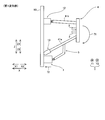
- the connecting member 5 is provided to connect the exciting portion 1 and the holding member 4. Specifically, the excitation unit 1 is connected to one end surface of the connecting member 5. Further, the holding member 4 is connected to the other end surface of the connecting member 5. In the present embodiment, the connecting member 5 has a flat plate shape. Further, the connecting member 5 is configured to connect the holding member 4 or the speckle-sharing interferometer 3 and the exciting unit 1. In the example shown in FIG. 1, the connecting member 5 connects the holding member 4 and the exciting portion 1. The detailed configuration of the connecting member 5 will be described later.
- the control unit 6 is configured to generate an image 61 (see FIG. 4) relating to the propagation of elastic waves by controlling the speckle-sharing interferometer 3. Further, the control unit 6 is configured to transmit an AC electric signal to the excitation unit 1 by controlling the signal generator 7. Further, the control unit 6 is configured to transmit an electric signal to the laser illumination 2. Further, the control unit 6 is configured to reduce the pressure inside the recess 12a (see FIG. 6) of the suction unit 12 by using the vacuum pump 10 by controlling the solenoid valve 11.
- the control unit 6 includes a processor such as a CPU (Central Processing Unit) or FPGA (Field Programmable Gate Array), a GPU (Graphics Processing Unit), and a computer including a volatile and / or non-volatile memory. ..
- the signal generator 7 is configured to generate an AC electric signal to be transmitted to the excitation unit 1 under the control of the control unit 6. Further, the signal generator 7 is configured to generate an electric signal to be transmitted to the laser illumination 2 under the control of the control unit 6.
- the display unit 8 is configured to display an image 61 relating to the propagation of elastic waves in the inspection target 90 created by the control unit 6.
- the display unit 8 includes, for example, a liquid crystal monitor.
- the operation input unit 9 is configured to be able to accept the operation input of the inspector.
- the operation input unit 9 includes, for example, a touch panel.
- the vacuum pump 10 is configured to suck the gas in the recess 12a (see FIG. 6) of the suction unit 12 under the control of the control unit 6.
- the suction unit 12 is configured to be adsorbed to the inspection target 90 by sucking the gas in the recess 12a of the suction unit 12 by the vacuum pump 10.
- control unit 6, the signal generator 7, and the display unit 8 are provided in the portable control device 110.
- the control device 110 is provided with, for example, a backpack (not shown). As a result, the inspector can inspect the inspection target 90 while carrying the control device 110 on his back. Further, the vacuum pump 10 is provided in the control device 110 so that it can be carried together with the control device 110.
- the inspection target 90 is, for example, a structure.
- the inspection target 90 is an aircraft body. More specifically, it is a coated steel plate used for an aircraft body, in which a coating film 92 is coated on a surface of a steel plate 91.
- the defect inspection device 100 inspects the defect of the inspection target 90.
- FIG. 1 shows an example of inspecting an inspection target 90 in which a crack 93 and a peeling 94 are generated as defects.
- the defect inspection apparatus 100 is in a state where the laser illumination 2 and the speckle-sharing interferometer 3 and the inspection target 90 (inspection region 90a) are arranged to face each other. , It is configured to inspect the inspection target 90. Specifically, the defect inspection device 100 is configured to irradiate the inspection region 90a of the inspection target 90 with a laser beam.
- the holding member 4 includes a first leg portion 41a, a second leg portion 41b, and a third leg portion 41c as a plurality of leg portions 41.
- the exciting portion 1 is provided on any one of the plurality of leg portions 41. In the example shown in FIG. 2, the exciting portion 1 is provided on the first leg portion 41a.
- the exciting portion 1 is provided on the first leg portion 41a in a state where the relative position with the first leg portion 41a is substantially fixed via the connecting member 5.
- the excitation unit 1 comes into contact with the inspection target 90 at a position where the relative position with respect to the speckle-sharing interferometer 3 is preset. , Is provided on the first leg portion 41a.
- the preset position is a position where the relative position of the excitation unit 1 with respect to the speckle-sharing interferometer 3 becomes substantially equal for each inspection.
- the holding member 4 is provided with a grip portion 4a.
- the inspector brings the defect inspection device 100 into contact with the inspection target 90 while gripping the grip portion 4a, and operates the operation input unit 9 to attract the defect inspection device 100 to the inspection target 90. Since the defect inspection device 100 can be fixed in contact with the inspection target 90 via the suction portion 12, the inspector can carry out the inspection without grasping it.
- the speckle-sharing interferometer 3 includes an interferometer 30 and an image sensor 31.
- the interference unit 30 includes a beam splitter 32, a phase shifter 33, a first reflector 34, a second reflector 35, and a condenser lens 36.
- the image sensor 31 is an example of the "imaging unit" in the claims.
- the beam splitter 32 is a half mirror, and is arranged at a position where the laser beam reflected on the surface of the inspection target 90 is incident.
- the first reflecting mirror 34 is arranged so as to have an angle of 45 degrees with respect to the reflecting surface of the beam splitter 32 on the optical path of the laser light reflected by the beam splitter 32.
- the second reflecting mirror 35 is arranged so as to be slightly inclined from an angle of 45 degrees with respect to the reflecting surface of the beam splitter 32 on the optical path of the laser light passing through the beam splitter 32.
- the phase shifter 33 is arranged between the beam splitter 32 and the first reflecting mirror 34, and changes (shifts) the phase of the transmitted laser light under the control of the control unit 6.
- the phase shifter 33 includes, for example, an optical member.
- the optical member constituting the phase shifter 33 includes, for example, a composite lens pair in which two lenses having different refractive indexes of transmitted laser light are integrated.
- the image sensor 31 has a large number of detection elements, and is a laser beam 60a that is reflected by the beam splitter 32 and then reflected by the first reflector 34 to pass through the beam splitter 32, and a second reflector after passing through the beam splitter 32. It is arranged on the optical path of the laser beam 60b reflected by the beam splitter 32 and reflected by the beam splitter 32.
- the condenser lens 36 is arranged between the beam splitter 32 and the image sensor 31, and condenses the laser beam 60a transmitted through the beam splitter 32 and the laser beam 60b reflected by the beam splitter 32.
- the control unit 6 operates the phase shifter 33 arranged in the speckle-sharing interferometer 3 with an actuator (not shown) to change the phase of the transmitted laser beam. As a result, the phase difference between the laser light reflected at the point A 95 and the laser light reflected at the point B 96 changes.
- Each detection element of the image sensor 31 detects the intensity of the interference light in which these two laser beams interfere with each other.
- the control unit 6 controls the vibration of the excitation unit 1 and the timing of irradiation of the laser beam of the laser illumination 2 via the signal generator 7, and causes the image to be captured while changing the phase shift amount.
- the phase shift amount is changed by ⁇ / 4.
- the control unit 6 processes the detection signal from each detection element according to the following procedure, and acquires an image 61 relating to the propagation of elastic waves.
- B is a complex amplitude and is expressed as in the equation (3).
- B Aexp (i ⁇ ): Complex amplitude ... (3)
- the complex amplitude B is the image information (two-dimensional spatial information of the complex amplitude) that is the basis for outputting the image 61 relating to the propagation of elastic waves. From the approximate equation obtained by removing the constant term C from the equation (2), a moving image (30 to 60 frames) displaying the optical phase change at each phase time ⁇ (0 ⁇ ⁇ ⁇ 2 ⁇ ) of the vibration is constructed, and the elastic wave is generated. It is output as an image 61 related to propagation.
- a spatial filter may be appropriately applied to the complex amplitude B in order to remove noise.
- the phase shift amount and the laser irradiation timing step ( ⁇ / 4 and T / 8, respectively in the above example, where T is the vibration cycle) are not limited to this. In this case, the calculation formula is different from the above formulas (1) to (3).
- FIG. 4 shows an example in which a portion 80 having a discontinuous vibration state is generated when a crack 93 is generated as a defect. Further, FIG. 4 shows an example in which a portion 81 having a discontinuous vibration state occurs when the peeling 94 occurs as a defect.
- the excitation unit 1 is composed of a housing 1a, a vibrator 1b, and a vibration absorbing member 1c.
- the housing 1a is connected to the first leg portion 41a via the connecting member 5. Specifically, the housing 1a is connected to the connecting member 5 via the exciting portion connecting member 5a. Further, the exciting portion connecting member 5a has a joint portion 5b. The housing 1a is provided on the exciting portion connecting member 5a so as to be rotatable around the joint portion 5b. Therefore, even when the first leg portion 41a is not perpendicular to the inspection target 90, the excitation portion 1 can be rotated by the joint portion 5b to bring the excitation portion 1 into vertical contact with the inspection target 90. can.
- a vibrator 1b and a vibration absorbing member 1c are provided inside the housing 1a.
- the vibrator 1b is configured so that a current is supplied via the cable 20.
- the oscillator 1b vibrates the vibrating surface 1e of the oscillator 1b in the X direction by converting the voltage of the supplied current.
- the vibrator 1b is configured to excite an elastic wave to the inspection target 90 by bringing the vibration surface 1e into contact with the inspection target 90.
- the vibrator 1b includes, for example, a piezoelectric element.
- the vibration absorbing member 1c is provided between the exciting unit 1 and the speckle-sharing interferometer 3 (image sensor 31). That is, the vibration absorbing member 1c is provided in the middle of the connecting structure between the exciting portion 1 and the image sensor 31. Specifically, the vibration absorbing member 1c is provided between the housing 1a and the vibrator 1b. The vibration absorbing member 1c is provided to absorb the vibration from the exciting portion 1.
- the vibration absorbing member 1c includes, for example, an elastic member.
- the elastic member is, for example, a spring.
- the vibration absorbing member 1c has an appropriate spring constant based on the amplitude, frequency, etc. of the vibration of the vibrator 1b so that the vibration of the vibrator 1b can be suppressed from propagating to the housing 1a. It is composed of springs.
- the vibration absorbing member 1c is configured to apply an urging force that urges the vibrator 1b in the direction of the arrow 70 to the vibrator 1b. That is, in the example shown in FIG. 5, the vibration absorbing member 1c is arranged between the housing 1a and the vibrator 1b in a state of being contracted from the natural length.
- the exciting portion 1 is provided on the first leg portion 41a together with the suction portion 12. Specifically, the exciting portion 1 is provided on the first leg portion 41a together with the plurality of suction portions 12 via the connecting member 5.
- the excitation unit 1 is arranged between the two suction units 12. Further, the excitation unit 1 and the plurality of suction units 12 are arranged so as to be arranged along the Y direction. As a result, it is possible to prevent the suction portion 12 from being arranged in the inspection region 90a (see FIG. 2).
- the suction portion 12 has a recess 12a and a close contact portion 12b that is in close contact with the inspection target 90.
- the recess 12a is provided in the suction portion 12 so that the end surface on the opening side can come into contact with the inspection target 90.
- the close contact portion 12b is composed of an elastic member.
- the close contact portion 12b includes, for example, rubber.
- the close contact portion 12b is provided so as to surround the entire circumference of the end surface of the recess 12a on the opening side. Therefore, when the suction portion 12 is brought into contact with the inspection target 90, a closed space is formed by the recess 12a, the close contact portion 12b, and the inspection target 90. Further, the suction portion 12 is connected to the vacuum pump 10 via the tube 21.
- the suction unit 12 is configured such that the gas in the closed space is sucked by the vacuum pump 10 via the tube 21 to reduce the pressure in the closed space and to be adsorbed on the inspection target 90.
- the connecting member 5 includes a suction portion connecting member 5c.
- the suction unit 12 is connected to the connection member 5 via the suction unit connection member 5c.
- the suction portion connecting member 5c has a joint portion 5d.
- the suction portion 12 is provided on the suction portion connecting member 5c so as to be rotatable around the joint portion 5d. Therefore, even when the first leg portion 41a is not perpendicular to the inspection target 90, the suction portion 12 can be rotated by the joint portion 5d to bring the suction portion 12 into vertical contact with the inspection target 90. can. Therefore, the holding member 4 can be stably supported by the suction portion 12.
- the plurality of legs 41 have a hollow cylindrical shape. Further, the connecting member 5 is formed to be hollow.
- the cable 20 is housed inside the first leg portion 41a. Further, the tube 21 is housed inside the first leg portion 41a.
- the excitation unit 1 and the image pickup unit (image sensor 31) are connected via the holding member 4, so that the excitation unit 1 and the image pickup unit (image sensor 31) are connected to each other. It is possible to suppress the change in the relative position of. As a result, the reproducibility of the inspection can be improved.
- a vibration absorbing member 1c provided between the exciting unit 1 and the imaging unit (image sensor 31) and absorbing the vibration from the exciting unit 1 is further provided.
- the vibration from the excitation unit 1 from propagating to the image pickup unit (image sensor 31).
- the vibration of the image pickup unit (image sensor 31) due to the vibration from the excitation unit 1. Therefore, the image 61 relating to the propagation of elastic waves due to the vibration of the image pickup unit (image sensor 31). It is possible to suppress the generation of noise.
- the holding member 4 has an imaging unit holding unit (interferometer holding unit 40) that holds the imaging unit (image sensor 31) and an imaging unit holding unit (interferometer holding unit 40).
- the exciting portion 1 has one of the plurality of leg portions 41 (first leg portion 41a) via the connecting member 5. It is provided in.
- the excitation unit 1 and the image pickup unit (image sensor 31) are connected via the connecting member 5 and the first leg portion 41a, so that the relative position of the excitation unit 1 with respect to the image pickup unit (image sensor 31) changes. Can be easily suppressed.
- the excitation unit 1 when the first leg portion 41a is brought into contact with the inspection target 90, the excitation unit 1 is at a position where the relative position with respect to the image pickup unit (image sensor 31) is preset.
- the first leg portion 41a is provided so as to come into contact with the inspection target 90.
- the excitation unit 1 includes the housing 1a, the vibrator 1b, and the vibration absorbing member 1c, and the housing 1a is the first leg via the connecting member 5. It is connected to the portion 41a, the vibrator 1b and the vibration absorbing member 1c are provided inside the housing 1a, and the vibration absorbing member 1c is provided between the housing 1a and the vibrator 1b. .. As a result, the vibration absorbing member 1c can suppress the vibration from the vibrator 1b from propagating to the housing 1a. As a result, it is possible to suppress the vibration from the vibrator 1b from propagating to the image pickup unit (image sensor 31) via the housing 1a, the connecting member 5, and the first leg portion 41a.
- the vibration absorbing member 1c can urge the vibrator 1b, the vibrator 1b can be brought into close contact with the inspection target 90. As a result, even when the inspection target 90 is not a flat surface, it is possible to excite an elastic wave with respect to the inspection target 90, so that the inspection accuracy can be improved.
- the plurality of leg portions 41 are provided with a suction portion 12 that supports the holding member 4 by adsorbing to the inspection target 90, and the excitation portion 1 is a suction portion. It is provided on the first leg portion 41a together with the twelve. As a result, the holding member 4 and the exciting portion 1 are supported by the suction portion 12, so that the inspector can inspect without supporting the holding member 4. As a result, it is possible to reduce the burden on the inspector by comparing the configurations in which the holding member 4 is inspected while being supported by the inspector. Further, since the inspector can inspect without supporting the holding member 4, it is possible to prevent the inspector from giving vibration to the holding member 4.
- a contact member 13 that abuts on the inspection target 90 is provided on the plurality of legs 41 to excite.
- the portion 1 may be provided on the first leg portion 41a together with the contact member 13. Even with this configuration, the same effect as the configuration in which the excitation unit 1 is provided together with the suction unit 12 can be obtained.
- the excitation unit 1 is provided on the first leg unit 41a together with the plurality of suction units 12. As a result, the excitation unit 1 can be brought into close contact with the inspection target 90 by the plurality of suction units 12. Therefore, unlike the configuration in which the inspector abuts the excitation unit 1 on the inspection target 90 for inspection, the excitation unit 1 can be brought into close contact with the inspection target 90 by a predetermined suction force. As a result, it is possible to suppress the change in the degree of adhesion of the excitation unit 1 for each inspection, so that the reliability of the inspection can be improved.
- the excitation unit 1 is configured to excite elastic waves with respect to the inspection target 90 by supplying an electric current through the cable 20. , Is housed inside the first leg 41a. Thereby, for example, it is possible to suppress the complicated routing of the cable 20 as compared with the configuration in which the cable 20 is not housed inside the first leg portion 41a. As a result, the workability of the inspection can be improved.
- the exciting portion 1 may be provided on the first leg portion 41a together with the contact member 13.
- the abutting member 13 is made of, for example, a resin or an elastic member.
- the suction portion 12 is provided on the second leg portion 41b and the third leg portion 41c in which the excitation portion 1 is not provided.
- the second leg portion 41b and the third leg portion 41c are on the upper side (Z1 side), and the first leg portion 41a is on the lower side (Z2 side).
- the defect inspection device 100 is arranged so as to be.
- a moment as shown by an arrow 71 is generated with respect to the holding member 4. Therefore, as shown by the arrow 72, a force is applied to the excitation unit 1 to urge the inspection target 90. Therefore, even if the excitation unit 1 and the suction unit 12 are not provided, the excitation unit 1 can be brought into close contact with the inspection target 90.
- the first modification by configuring as described above, it is possible to suppress an increase in the number of parts as compared with a configuration in which the excitation unit 1 is provided together with the suction unit 12. Further, as compared with the configuration in which the excitation unit 1 is provided together with the suction unit 12, it is possible to suppress an increase in the force applied to the excitation unit 1. Therefore, it is possible to prevent the excitation unit 1 from being pressed more than necessary against the inspection target 90 by the force applied to the excitation unit 1 and the amplitude of the elastic wave propagating from the excitation unit 1 to be reduced. As a result, it is possible to suppress a decrease in inspection accuracy due to a small amplitude of elastic waves.
- the excitation unit 1 may be integrally provided inside or outside the suction unit 12.
- the excitation unit 1 is provided in the recess 12a of the suction unit 12, so that the excitation unit 1 is integrally formed inside the suction unit 12.
- the excitation unit 1 is integrally configured inside the suction unit 12, but as shown in FIG. 9, the excitation unit 1 is integrally configured outside the suction unit 12. It may have been.
- a recessed portion 1f may be provided on the inner surface of the excitation portion 1 in contact with the inspection target 90, and the inside of the recessed portion 1f may be depressurized by the vacuum pump 10 to form the suction portion 12.
- the number of parts to be attached to the first leg portion 41a is increased by the configuration as described above, as compared with the configuration in which the excitation portion 1 is provided together with the suction portion 12 for the first leg portion 41a. It can be suppressed. Further, the excitation unit 1 and the suction unit 12 can be integrated, and the handling of the holding member 4 can be suppressed from becoming complicated.
- the connecting member 5 may be configured so that the contact position of the excitation unit 1 with respect to the inspection target 90 can be adjusted.
- the connecting member 5 includes the first section 50, the second section 51, and the third section 52.
- the first section 50 and the second section 51 are configured to be expandable and contractible.
- the first section 50 is connected to the third section 52 via the joint 53.
- the first section portion 50 is configured to be rotatable around the joint portion 53.
- the first section portion 50 is connected to the first leg portion 41a via the joint portion 54.
- the first section portion 50 is configured to be rotatable around the joint portion 54.
- the second section 51 is connected to the third section 52 via the joint portion 55.
- the second section 51 is configured to be rotatable around the joint 55.
- the second section 51 is connected to the first leg 41a via the joint 56.
- the second section 51 is configured to be rotatable around the joint 56.
- the third section 52 is connected to the first section 50 via the joint 53. Further, the third section 52 is connected to the second section 51 via the joint 55. Further, an exciting portion 1 is provided at an end portion of the third node portion 52 opposite to the joint portion 53.
- the first section 50 and the second section 51 are arranged so as to be parallel to each other.
- the third section 52 is moved in the X direction, the first section 50 and the second section 51 rotate around the joint portion 54 and the joint portion 56, respectively.
- the third section 52 can be moved in the X direction while maintaining the angle of the third section 52 with respect to the inspection target 90. Therefore, the connecting member 5 can adjust the position of the excitation unit 1 in the X direction while maintaining the angle of the excitation unit 1 with respect to the inspection target 90.
- the connecting member 5 is configured as a so-called link mechanism.
- the connecting member 5 includes an urging member 5e that urges the excitation unit 1 with respect to the inspection target 90.
- the urging member 5e is provided between the second section 51 and the first leg 41a, and urges the second section 51 in the direction of the arrow 73.
- the urging force by the urging member 5e is applied to the urging unit 1 as an urging force in the direction of the arrow 74 via the second section 51 and the third section 52.
- the first leg portion 41a is provided with the suction portion 12, but the contact member 13 (see FIG. 7) may be provided instead of the suction portion 12.
- the position where the excitation unit 1 comes into contact with the inspection target 90 can be adjusted by the connecting member 5 as described above, so that, for example, the surface of the inspection target 90 has irregularities or is inspected. Even when the surface of the target 90 is curved, the excitation unit 1 can be brought into close contact with the inspection target 90. As a result, the exciting unit 1 can excite a predetermined elastic wave to the inspection target 90, so that it is possible to suppress a decrease in inspection accuracy.
- the connecting member 5 includes the urging member 5e that urges the excitation unit 1 with respect to the inspection target 90
- the surface of the inspection target 90 is inclined.
- the urging force of the urging member 5e allows the exciting portion 1 to be easily brought into close contact with the inspection target 90.
- the excitation unit 1 can excite a predetermined elastic wave to the inspection target 90, it is possible to easily suppress the deterioration of the inspection accuracy.
- the connecting member 5 may be configured to be rotatable in the circumferential direction centered on the first leg portion 41a.
- the connecting member 5 includes the fourth section portion 57 and the cylindrical portion 58.
- the fourth section 57 includes a first section member 57a and a second section member 57b extending in the Y direction, and a third section member 57c extending in the X direction.
- the fourth section 57 is formed by integrally forming the first section member 57a, the second section member 57b, and the third section member 57c.
- the first section member 57a and the second section member 57b are provided with a connecting portion 59a and a connecting portion 59b, respectively.
- the connecting portion 59a and the connecting portion 59b are configured so that the first section member 57a and the second section member 57b can be expanded and contracted in the Y direction, respectively.
- first section member 57a and the second section member 57b are each connected to the cylindrical portion 58.
- the cylindrical portion 58 is configured to be rotatable in the rotational direction around the center line 75 of the first leg portion 41a. Therefore, the connecting member 5 is configured so that the exciting portion 1 can be rotated around the first leg portion 41a. Further, the cylindrical portion 58 is configured to be movable in a direction along the first leg portion 41a. The inspector adjusts the position and rotation angle of the cylindrical portion 58 so that the exciting portion 1 is in a predetermined position with respect to the first leg portion 41a, and the position of the cylindrical portion 58 is fixed by the positioning member 42. , Inspect 90 to be inspected. In the example shown in FIG. 11, the first leg portion 41a is provided with the suction portion 12, but the contact member 13 (see FIG. 7) may be provided instead of the suction portion 12.
- the excitation portion 1 is rotated to excite the vehicle.
- the position of the part 1 can be adjusted.
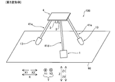
- the plurality of leg portions 41 include an exciting leg portion 41d provided with the exciting portion 1 and a support leg portion 41e for supporting the holding member 4.
- the fifth modification assumes a case where the defect inspection device 100 is arranged and inspected with respect to the inspection target 90 in the Z2 direction (lower side in the vertical direction).
- the elastic wave can be excited by the exciting leg portion 41d and the holding member 4 can be supported by the support leg portion 41e by the configuration as described above.
- the burden on the inspector can be reduced.
- the holding member 4 and the exciting portion 1 are supported by the contact member 13, the inspector can inspect without supporting the holding member 4.
- the inspector can inspect without supporting the holding member 4.
- it is possible to reduce the burden on the inspector by comparing the configurations in which the holding member 4 is inspected while being supported by the inspector.
- the inspector can inspect without supporting the holding member 4, it is possible to prevent the inspector from giving vibration to the holding member 4.
- the excitation unit 1 is provided on any one of the plurality of leg portions 41 (first leg portion 41a) is shown, but the present invention is not limited to this.
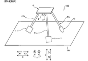
- the exciting portion 1 may be provided on at least two leg portions 41 among the plurality of leg portions 41 via the connecting member 5.
- the excitation unit 1 is arranged on the first leg portion 41a and the second leg portion 41b.
- elastic waves can be propagated from a plurality of locations (two locations) by configuring as described above.
- elastic waves can be propagated from a plurality of different locations, and unlike the configuration in which elastic waves are propagated from one location, the weakening of vibration propagation increases the number of parts where it is difficult to detect defects. It can be suppressed.
- each of the plurality of leg portions 41 is provided with a light-shielding member 14 that covers the space 43 surrounded by the plurality of leg portions 41.
- the light-shielding member 14 is shown with hatching.
- the light-shielding member 14 is provided on each of the three legs 41.
- the four legs 41 are outside the four corners (four corners) of the inspection area 90a (see FIG. 2).
- the light-shielding member 14 may be provided so as to cover the four legs 41 at the time of imaging.
- the influence of external light such as sunlight can be removed when inspecting outdoors. Further, since it is possible to prevent the laser beam from leaking to the outside from the inspection area 90a (see FIG. 2), it is possible to prevent the inspector from looking into the laser beam. As a result, the safety of the inspector can be ensured.
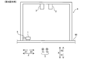
- the exciting unit 1, the laser illumination 2, and the speckle-sharing interferometer 3 may be provided on the holding member 4 having a box shape. As shown in FIG. 15, when the holding member 4 having a box shape is used, the exciting portion 1 may be provided on the side surface of the holding member 4 via the connecting member 5.
- the present invention is not limited to this.
- the interference unit 30 and the image sensor 31 may be provided separately.
- the interferometer 30 may be configured by an interferometer other than the speckle-sharing interferometer 3.
- the defect inspection device 100 includes the vibration absorbing member 1c
- the present invention is not limited to this.
- the defect inspection device 100 does not have to include the vibration absorbing member 1c.
- the housing 1a of the excitation unit 1 and the vibrator 1b may be fixed with a resin material or the like.
- the excitation unit 1 used in contact with the surface of the inspection target 90 is used, but the present invention is not limited to this.
- a powerful speaker or the like placed at a position where it does not come into contact with the surface of the inspection target 90 may be used as the excitation unit 1.
- a window or various optical filters are provided on the optical path until the reflected light from the inspection target 90 is incident on the image sensor 31 for the purpose of protecting optical components and improving the SN ratio of the device. It may be arranged.
- the condenser lens 36 is arranged between the beam splitter 32 and the image sensor 31, but the present invention is not limited to this arrangement.
- the condenser lens 36 may be composed of a plurality of lenses or a plurality of lens groups.
- the present invention is not limited to this.
- the signal generator 7, the excitation unit 1, and the laser illumination 2 may be wirelessly connected.
- the holding member 4 may include or configure four legs 41.
- the number of legs 41 included in the holding member 4 may be any number.
- the connecting member 5 may have any shape.
- the exciting portion 1 may be connected to the first leg portion 41a by a string-shaped connecting member 5.
- the defect inspection device 100 may inspect a bridge or the like.
- the suction portion 12 may not be attracted to the bridge girder or the like, so it is preferable to provide the leg portion 41 with the contact member 13.
- An exciting part that excites elastic waves in the inspection target, Laser illumination that irradiates the inspection target with laser light, An interference unit that interferes with laser light reflected from different positions of the inspection target excited by the excitation unit, and an interference unit.
- An image pickup unit that captures the interfered laser beam, A holding member that holds the image pickup unit so that it can be arranged at a position separated from the inspection target by a predetermined distance.
- a connecting member that connects the holding member or the imaging unit and the excitation unit,
- a defect inspection apparatus including a control unit that generates an image relating to the propagation of an elastic wave to be inspected based on an interfered laser beam imaged by the image pickup unit.
- the holding member has an image pickup unit holding portion for holding the image pickup unit and a plurality of legs provided in the image pickup unit holding unit.
- the holding member has an image pickup unit holding portion for holding the image pickup unit and a plurality of legs provided in the image pickup unit holding unit.
- the excitation unit is provided on the leg portion so that when the leg portion is brought into contact with the inspection target, the leg portion comes into contact with the inspection target at a position in which a relative position with respect to the image pickup unit is preset. , Item 3 or 4.
- the excitation unit includes a housing, a vibrator, and a vibration absorbing member.
- the housing is connected to the legs via the connecting member, and is connected to the legs.
- the vibrator and the vibration absorbing member are provided inside the housing, and the vibrator and the vibration absorbing member are provided inside the housing.
- Item 3 The defect inspection device according to item 3 or 4, wherein the vibration absorbing member is provided between the housing and the vibrator.
- the plurality of legs are provided with a suction portion that supports the holding member by adsorbing to the inspection target, or a contact member that comes into contact with the inspection target.
- Item 3 The defect inspection device according to item 3 or 4, wherein the exciting portion is provided on the leg portion together with the suction portion or the contact member.
- the excitation unit is configured to excite the elastic wave with respect to the inspection target by supplying an electric current via a cable.
- each of the plurality of legs is provided with a light-shielding member that covers a space surrounded by the plurality of legs.
Landscapes
- Physics & Mathematics (AREA)
- General Physics & Mathematics (AREA)
- General Health & Medical Sciences (AREA)
- Chemical & Material Sciences (AREA)
- Analytical Chemistry (AREA)
- Biochemistry (AREA)
- Life Sciences & Earth Sciences (AREA)
- Health & Medical Sciences (AREA)
- Immunology (AREA)
- Pathology (AREA)
- Acoustics & Sound (AREA)
- Optics & Photonics (AREA)
- Investigating Or Analyzing Materials By The Use Of Ultrasonic Waves (AREA)
- Investigating Materials By The Use Of Optical Means Adapted For Particular Applications (AREA)
Priority Applications (4)
| Application Number | Priority Date | Filing Date | Title |
|---|---|---|---|
| US18/013,401 US12345653B2 (en) | 2020-07-02 | 2020-07-02 | Defect inspection apparatus |
| PCT/JP2020/026071 WO2022003916A1 (ja) | 2020-07-02 | 2020-07-02 | 欠陥検査装置 |
| CN202080103681.8A CN115997104B (zh) | 2020-07-02 | 2020-07-02 | 缺陷检查装置 |
| JP2022532965A JP7444257B2 (ja) | 2020-07-02 | 2020-07-02 | 欠陥検査装置 |
Applications Claiming Priority (1)
| Application Number | Priority Date | Filing Date | Title |
|---|---|---|---|
| PCT/JP2020/026071 WO2022003916A1 (ja) | 2020-07-02 | 2020-07-02 | 欠陥検査装置 |
Publications (1)
| Publication Number | Publication Date |
|---|---|
| WO2022003916A1 true WO2022003916A1 (ja) | 2022-01-06 |
Family
ID=79315004
Family Applications (1)
| Application Number | Title | Priority Date | Filing Date |
|---|---|---|---|
| PCT/JP2020/026071 Ceased WO2022003916A1 (ja) | 2020-07-02 | 2020-07-02 | 欠陥検査装置 |
Country Status (4)
| Country | Link |
|---|---|
| US (1) | US12345653B2 (https=) |
| JP (1) | JP7444257B2 (https=) |
| CN (1) | CN115997104B (https=) |
| WO (1) | WO2022003916A1 (https=) |
Families Citing this family (1)
| Publication number | Priority date | Publication date | Assignee | Title |
|---|---|---|---|---|
| JP2024076652A (ja) * | 2022-11-25 | 2024-06-06 | 株式会社大気社 | 検査装置および検査方法 |
Citations (4)
| Publication number | Priority date | Publication date | Assignee | Title |
|---|---|---|---|---|
| JP2002177271A (ja) * | 2000-12-07 | 2002-06-25 | Ge Medical Systems Global Technology Co Llc | 超音波プローブ製造方法、超音波プローブ、および超音波撮像装置 |
| US20140118530A1 (en) * | 2012-10-31 | 2014-05-01 | The Boeing Company | Thermal Sound Inspection System |
| JP2014119441A (ja) * | 2012-12-19 | 2014-06-30 | Toshiba Corp | 超音波探傷装置及び方法 |
| JP2017219318A (ja) * | 2016-06-02 | 2017-12-14 | 株式会社島津製作所 | 欠陥検査方法及び欠陥検査装置 |
Family Cites Families (18)
| Publication number | Priority date | Publication date | Assignee | Title |
|---|---|---|---|---|
| JPS6121961U (ja) * | 1984-07-16 | 1986-02-08 | 神奈川県 | 超音波探触子の保持装置 |
| JPH10227768A (ja) | 1997-02-13 | 1998-08-25 | Aisin Seiki Co Ltd | 雨滴検出装置 |
| JPH10253604A (ja) | 1997-03-07 | 1998-09-25 | Matsushita Electric Ind Co Ltd | 超音波探触子 |
| JPH10308997A (ja) | 1997-05-08 | 1998-11-17 | Olympus Optical Co Ltd | 超音波振動子 |
| US6134006A (en) * | 1998-02-25 | 2000-10-17 | Becthel Bwxt Idaho, Llc | Imaging photorefractive optical vibration measurement method and device |
| JPH11315883A (ja) * | 1998-04-30 | 1999-11-16 | Canon Inc | 除振装置、露光装置およびデバイス製造方法 |
| WO2005006416A1 (ja) * | 2003-07-09 | 2005-01-20 | Nikon Corporation | 結合装置、露光装置、及びデバイス製造方法 |
| CN100508119C (zh) | 2003-07-09 | 2009-07-01 | 株式会社尼康 | 曝光装置、器件制造方法 |
| JP4244172B2 (ja) * | 2003-08-13 | 2009-03-25 | 株式会社Ihi | 高温用超音波探触子 |
| JP4801457B2 (ja) * | 2006-02-02 | 2011-10-26 | 株式会社リコー | 表面欠陥検査装置、表面欠陥検査方法及び表面欠陥検査プログラム |
| JP5456010B2 (ja) * | 2011-08-31 | 2014-03-26 | 三菱電機株式会社 | 薄板検査装置 |
| TWI585519B (zh) * | 2015-11-06 | 2017-06-01 | 艾斯邁科技股份有限公司 | 光罩檢測裝置及其方法 |
| CN108088913B (zh) * | 2018-01-09 | 2023-08-25 | 东莞理工学院 | 用于钢轨轨底探伤的压电超声导波探头及其探伤方法 |
| CN208282930U (zh) * | 2018-05-08 | 2018-12-25 | 辛迈 | 基于振动分析的动力机组无线监测系统 |
| CN208872452U (zh) * | 2019-01-08 | 2019-05-17 | 中国大唐集团新能源科学技术研究院有限公司 | 一种便携式风电机组用螺栓预紧力检测设备 |
| CN210525404U (zh) * | 2019-03-01 | 2020-05-15 | 郑淑选 | 一种水泥混凝土振实装置 |
| CN209416526U (zh) * | 2019-03-15 | 2019-09-20 | 江苏万宝电子有限公司 | 一种电机轴承用热电阻 |
| US11898926B2 (en) * | 2019-09-13 | 2024-02-13 | Technical Manufacturing Corporation | Inspection apparatus and methods for precision vibration-isolation tabletops |
-
2020
- 2020-07-02 JP JP2022532965A patent/JP7444257B2/ja active Active
- 2020-07-02 US US18/013,401 patent/US12345653B2/en active Active
- 2020-07-02 WO PCT/JP2020/026071 patent/WO2022003916A1/ja not_active Ceased
- 2020-07-02 CN CN202080103681.8A patent/CN115997104B/zh active Active
Patent Citations (4)
| Publication number | Priority date | Publication date | Assignee | Title |
|---|---|---|---|---|
| JP2002177271A (ja) * | 2000-12-07 | 2002-06-25 | Ge Medical Systems Global Technology Co Llc | 超音波プローブ製造方法、超音波プローブ、および超音波撮像装置 |
| US20140118530A1 (en) * | 2012-10-31 | 2014-05-01 | The Boeing Company | Thermal Sound Inspection System |
| JP2014119441A (ja) * | 2012-12-19 | 2014-06-30 | Toshiba Corp | 超音波探傷装置及び方法 |
| JP2017219318A (ja) * | 2016-06-02 | 2017-12-14 | 株式会社島津製作所 | 欠陥検査方法及び欠陥検査装置 |
Also Published As
| Publication number | Publication date |
|---|---|
| US12345653B2 (en) | 2025-07-01 |
| JP7444257B2 (ja) | 2024-03-06 |
| CN115997104B (zh) | 2025-08-01 |
| JPWO2022003916A1 (https=) | 2022-01-06 |
| CN115997104A (zh) | 2023-04-21 |
| US20230251204A1 (en) | 2023-08-10 |
Similar Documents
| Publication | Publication Date | Title |
|---|---|---|
| US10254252B2 (en) | Surface and subsurface detection sensor | |
| CN107462581B (zh) | 缺陷检测方法以及缺陷检测装置 | |
| US6940602B2 (en) | Method and device for high-speed interferential microscopic imaging of an object | |
| JP7095751B2 (ja) | 欠陥検査装置および欠陥検査方法 | |
| US20210080399A1 (en) | Defect inspection apparatus | |
| CN114746713A (zh) | 用于成像和干涉测量的设备和方法 | |
| WO2011016146A1 (ja) | 干渉顕微鏡及び測定装置 | |
| JP7326292B2 (ja) | 基板上のターゲット構造の位置を決定するための装置及び方法 | |
| JP7099545B2 (ja) | 欠陥検査装置および欠陥検査方法 | |
| WO2021145034A1 (ja) | 欠陥検査装置および欠陥検査方法 | |
| WO2013125723A1 (ja) | 照明方法および顕微観察装置 | |
| WO2022059710A1 (ja) | 欠陥検査装置 | |
| WO2022003916A1 (ja) | 欠陥検査装置 | |
| JP2005517177A (ja) | 組立デバイスにおける欠陥を検出するためのスペックル干渉計の使用 | |
| KR101424840B1 (ko) | 광탄성 측정방법 및 그 장치 | |
| WO2016104223A1 (ja) | 波面歪み量測定装置、波面補償装置、光学測定装置、および方法 | |
| WO2021149307A1 (ja) | 欠陥検査装置および欠陥検査方法 | |
| WO2022239522A1 (ja) | 欠陥検査装置および欠陥検査方法 | |
| US5734471A (en) | Method of adjusting sample position in light wave interference apparatus | |
| NO322717B1 (no) | System og fremgangsmate for maling av egenskaper i eller under overflaten til et materiale, samt anvendelse av dette | |
| JP7632621B2 (ja) | 欠陥検査システム、欠陥検査装置、および、欠陥検査方法 | |
| JP7107434B2 (ja) | 干渉画像撮像装置 | |
| KR102786763B1 (ko) | 비접촉식 광음향 검사 장치 | |
| JP2010091716A (ja) | 光弾性変調器およびそれを備えた光弾性測定装置 | |
| WO2026021821A1 (en) | Apparatus for acquiring images by optical coherence tomography |
Legal Events
| Date | Code | Title | Description |
|---|---|---|---|
| 121 | Ep: the epo has been informed by wipo that ep was designated in this application |
Ref document number: 20943161 Country of ref document: EP Kind code of ref document: A1 |
|
| ENP | Entry into the national phase |
Ref document number: 2022532965 Country of ref document: JP Kind code of ref document: A |
|
| NENP | Non-entry into the national phase |
Ref country code: DE |
|
| 122 | Ep: pct application non-entry in european phase |
Ref document number: 20943161 Country of ref document: EP Kind code of ref document: A1 |
|
| WWG | Wipo information: grant in national office |
Ref document number: 18013401 Country of ref document: US |
|
| WWG | Wipo information: grant in national office |
Ref document number: 202080103681.8 Country of ref document: CN |