WO2022003759A1 - Robot de peinture - Google Patents
Robot de peinture Download PDFInfo
- Publication number
- WO2022003759A1 WO2022003759A1 PCT/JP2020/025473 JP2020025473W WO2022003759A1 WO 2022003759 A1 WO2022003759 A1 WO 2022003759A1 JP 2020025473 W JP2020025473 W JP 2020025473W WO 2022003759 A1 WO2022003759 A1 WO 2022003759A1
- Authority
- WO
- WIPO (PCT)
- Prior art keywords
- explosion
- nozzle head
- nozzle
- gas
- painting robot
- Prior art date
Links
- 238000010422 painting Methods 0.000 title claims abstract description 60
- 239000000758 substrate Substances 0.000 claims abstract description 23
- 238000001514 detection method Methods 0.000 claims abstract description 5
- 239000007789 gas Substances 0.000 claims description 97
- 239000011261 inert gas Substances 0.000 claims description 35
- 239000003973 paint Substances 0.000 claims description 31
- 230000002093 peripheral effect Effects 0.000 claims description 12
- 239000000463 material Substances 0.000 claims description 6
- 238000007599 discharging Methods 0.000 claims 1
- 230000017525 heat dissipation Effects 0.000 abstract description 10
- 238000009529 body temperature measurement Methods 0.000 abstract 3
- 238000010276 construction Methods 0.000 abstract 1
- 239000000919 ceramic Substances 0.000 description 9
- 210000000707 wrist Anatomy 0.000 description 9
- 239000011248 coating agent Substances 0.000 description 7
- 238000000576 coating method Methods 0.000 description 7
- 238000001816 cooling Methods 0.000 description 7
- 238000010586 diagram Methods 0.000 description 4
- 230000001965 increasing effect Effects 0.000 description 4
- 238000004880 explosion Methods 0.000 description 3
- 229910052751 metal Inorganic materials 0.000 description 3
- 239000002184 metal Substances 0.000 description 3
- XEEYBQQBJWHFJM-UHFFFAOYSA-N Iron Chemical compound [Fe] XEEYBQQBJWHFJM-UHFFFAOYSA-N 0.000 description 2
- 229910052782 aluminium Inorganic materials 0.000 description 2
- XAGFODPZIPBFFR-UHFFFAOYSA-N aluminium Chemical compound [Al] XAGFODPZIPBFFR-UHFFFAOYSA-N 0.000 description 2
- 238000000889 atomisation Methods 0.000 description 2
- 230000000694 effects Effects 0.000 description 2
- 230000020169 heat generation Effects 0.000 description 2
- 238000009434 installation Methods 0.000 description 2
- 229910052451 lead zirconate titanate Inorganic materials 0.000 description 2
- 239000003960 organic solvent Substances 0.000 description 2
- 230000008961 swelling Effects 0.000 description 2
- XLYOFNOQVPJJNP-UHFFFAOYSA-N water Substances O XLYOFNOQVPJJNP-UHFFFAOYSA-N 0.000 description 2
- RYGMFSIKBFXOCR-UHFFFAOYSA-N Copper Chemical compound [Cu] RYGMFSIKBFXOCR-UHFFFAOYSA-N 0.000 description 1
- 229910003378 NaNbO3 Inorganic materials 0.000 description 1
- 230000002159 abnormal effect Effects 0.000 description 1
- 230000006399 behavior Effects 0.000 description 1
- 229910010293 ceramic material Inorganic materials 0.000 description 1
- 239000004020 conductor Substances 0.000 description 1
- 229910052802 copper Inorganic materials 0.000 description 1
- 239000010949 copper Substances 0.000 description 1
- 230000002542 deteriorative effect Effects 0.000 description 1
- 230000002708 enhancing effect Effects 0.000 description 1
- 230000005621 ferroelectricity Effects 0.000 description 1
- 229910052742 iron Inorganic materials 0.000 description 1
- HFGPZNIAWCZYJU-UHFFFAOYSA-N lead zirconate titanate Chemical compound [O-2].[O-2].[O-2].[O-2].[O-2].[Ti+4].[Zr+4].[Pb+2] HFGPZNIAWCZYJU-UHFFFAOYSA-N 0.000 description 1
- 230000007257 malfunction Effects 0.000 description 1
- 238000004519 manufacturing process Methods 0.000 description 1
- 238000000034 method Methods 0.000 description 1
- 239000011347 resin Substances 0.000 description 1
- 229920005989 resin Polymers 0.000 description 1
- 230000000630 rising effect Effects 0.000 description 1
- 239000004065 semiconductor Substances 0.000 description 1
- MUPJWXCPTRQOKY-UHFFFAOYSA-N sodium;niobium(5+);oxygen(2-) Chemical compound [O-2].[O-2].[O-2].[Na+].[Nb+5] MUPJWXCPTRQOKY-UHFFFAOYSA-N 0.000 description 1
- 239000007921 spray Substances 0.000 description 1
- 230000009466 transformation Effects 0.000 description 1
Images


Classifications
-
- B—PERFORMING OPERATIONS; TRANSPORTING
- B05—SPRAYING OR ATOMISING IN GENERAL; APPLYING FLUENT MATERIALS TO SURFACES, IN GENERAL
- B05B—SPRAYING APPARATUS; ATOMISING APPARATUS; NOZZLES
- B05B15/00—Details of spraying plant or spraying apparatus not otherwise provided for; Accessories
-
- B—PERFORMING OPERATIONS; TRANSPORTING
- B05—SPRAYING OR ATOMISING IN GENERAL; APPLYING FLUENT MATERIALS TO SURFACES, IN GENERAL
- B05B—SPRAYING APPARATUS; ATOMISING APPARATUS; NOZZLES
- B05B1/00—Nozzles, spray heads or other outlets, with or without auxiliary devices such as valves, heating means
- B05B1/14—Nozzles, spray heads or other outlets, with or without auxiliary devices such as valves, heating means with multiple outlet openings; with strainers in or outside the outlet opening
-
- B—PERFORMING OPERATIONS; TRANSPORTING
- B05—SPRAYING OR ATOMISING IN GENERAL; APPLYING FLUENT MATERIALS TO SURFACES, IN GENERAL
- B05B—SPRAYING APPARATUS; ATOMISING APPARATUS; NOZZLES
- B05B12/00—Arrangements for controlling delivery; Arrangements for controlling the spray area
- B05B12/08—Arrangements for controlling delivery; Arrangements for controlling the spray area responsive to condition of liquid or other fluent material to be discharged, of ambient medium or of target ; responsive to condition of spray devices or of supply means, e.g. pipes, pumps or their drive means
-
- B—PERFORMING OPERATIONS; TRANSPORTING
- B05—SPRAYING OR ATOMISING IN GENERAL; APPLYING FLUENT MATERIALS TO SURFACES, IN GENERAL
- B05B—SPRAYING APPARATUS; ATOMISING APPARATUS; NOZZLES
- B05B13/00—Machines or plants for applying liquids or other fluent materials to surfaces of objects or other work by spraying, not covered by groups B05B1/00 - B05B11/00
- B05B13/02—Means for supporting work; Arrangement or mounting of spray heads; Adaptation or arrangement of means for feeding work
- B05B13/04—Means for supporting work; Arrangement or mounting of spray heads; Adaptation or arrangement of means for feeding work the spray heads being moved during spraying operation
- B05B13/0431—Means for supporting work; Arrangement or mounting of spray heads; Adaptation or arrangement of means for feeding work the spray heads being moved during spraying operation with spray heads moved by robots or articulated arms, e.g. for applying liquid or other fluent material to 3D-surfaces
-
- B—PERFORMING OPERATIONS; TRANSPORTING
- B05—SPRAYING OR ATOMISING IN GENERAL; APPLYING FLUENT MATERIALS TO SURFACES, IN GENERAL
- B05B—SPRAYING APPARATUS; ATOMISING APPARATUS; NOZZLES
- B05B15/00—Details of spraying plant or spraying apparatus not otherwise provided for; Accessories
- B05B15/14—Arrangements for preventing or controlling structural damage to spraying apparatus or its outlets, e.g. for breaking at desired places; Arrangements for handling or replacing damaged parts
-
- B—PERFORMING OPERATIONS; TRANSPORTING
- B25—HAND TOOLS; PORTABLE POWER-DRIVEN TOOLS; MANIPULATORS
- B25J—MANIPULATORS; CHAMBERS PROVIDED WITH MANIPULATION DEVICES
- B25J11/00—Manipulators not otherwise provided for
- B25J11/0075—Manipulators for painting or coating
-
- B—PERFORMING OPERATIONS; TRANSPORTING
- B25—HAND TOOLS; PORTABLE POWER-DRIVEN TOOLS; MANIPULATORS
- B25J—MANIPULATORS; CHAMBERS PROVIDED WITH MANIPULATION DEVICES
- B25J13/00—Controls for manipulators
- B25J13/08—Controls for manipulators by means of sensing devices, e.g. viewing or touching devices
- B25J13/087—Controls for manipulators by means of sensing devices, e.g. viewing or touching devices for sensing other physical parameters, e.g. electrical or chemical properties
-
- B—PERFORMING OPERATIONS; TRANSPORTING
- B25—HAND TOOLS; PORTABLE POWER-DRIVEN TOOLS; MANIPULATORS
- B25J—MANIPULATORS; CHAMBERS PROVIDED WITH MANIPULATION DEVICES
- B25J19/00—Accessories fitted to manipulators, e.g. for monitoring, for viewing; Safety devices combined with or specially adapted for use in connection with manipulators
- B25J19/0025—Means for supplying energy to the end effector
-
- B—PERFORMING OPERATIONS; TRANSPORTING
- B25—HAND TOOLS; PORTABLE POWER-DRIVEN TOOLS; MANIPULATORS
- B25J—MANIPULATORS; CHAMBERS PROVIDED WITH MANIPULATION DEVICES
- B25J19/00—Accessories fitted to manipulators, e.g. for monitoring, for viewing; Safety devices combined with or specially adapted for use in connection with manipulators
- B25J19/0054—Cooling means
-
- B—PERFORMING OPERATIONS; TRANSPORTING
- B25—HAND TOOLS; PORTABLE POWER-DRIVEN TOOLS; MANIPULATORS
- B25J—MANIPULATORS; CHAMBERS PROVIDED WITH MANIPULATION DEVICES
- B25J19/00—Accessories fitted to manipulators, e.g. for monitoring, for viewing; Safety devices combined with or specially adapted for use in connection with manipulators
- B25J19/0075—Means for protecting the manipulator from its environment or vice versa
- B25J19/0079—Means for protecting the manipulator from its environment or vice versa using an internal pressure system
-
- B—PERFORMING OPERATIONS; TRANSPORTING
- B25—HAND TOOLS; PORTABLE POWER-DRIVEN TOOLS; MANIPULATORS
- B25J—MANIPULATORS; CHAMBERS PROVIDED WITH MANIPULATION DEVICES
- B25J9/00—Programme-controlled manipulators
- B25J9/16—Programme controls
- B25J9/1674—Programme controls characterised by safety, monitoring, diagnostic
-
- B—PERFORMING OPERATIONS; TRANSPORTING
- B05—SPRAYING OR ATOMISING IN GENERAL; APPLYING FLUENT MATERIALS TO SURFACES, IN GENERAL
- B05B—SPRAYING APPARATUS; ATOMISING APPARATUS; NOZZLES
- B05B1/00—Nozzles, spray heads or other outlets, with or without auxiliary devices such as valves, heating means
- B05B1/02—Nozzles, spray heads or other outlets, with or without auxiliary devices such as valves, heating means designed to produce a jet, spray, or other discharge of particular shape or nature, e.g. in single drops, or having an outlet of particular shape
- B05B1/08—Nozzles, spray heads or other outlets, with or without auxiliary devices such as valves, heating means designed to produce a jet, spray, or other discharge of particular shape or nature, e.g. in single drops, or having an outlet of particular shape of pulsating nature, e.g. delivering liquid in successive separate quantities ; Fluidic oscillators
- B05B1/083—Nozzles, spray heads or other outlets, with or without auxiliary devices such as valves, heating means designed to produce a jet, spray, or other discharge of particular shape or nature, e.g. in single drops, or having an outlet of particular shape of pulsating nature, e.g. delivering liquid in successive separate quantities ; Fluidic oscillators the pulsating mechanism comprising movable parts
- B05B1/086—Nozzles, spray heads or other outlets, with or without auxiliary devices such as valves, heating means designed to produce a jet, spray, or other discharge of particular shape or nature, e.g. in single drops, or having an outlet of particular shape of pulsating nature, e.g. delivering liquid in successive separate quantities ; Fluidic oscillators the pulsating mechanism comprising movable parts with a resiliently deformable element, e.g. sleeve
-
- B—PERFORMING OPERATIONS; TRANSPORTING
- B05—SPRAYING OR ATOMISING IN GENERAL; APPLYING FLUENT MATERIALS TO SURFACES, IN GENERAL
- B05B—SPRAYING APPARATUS; ATOMISING APPARATUS; NOZZLES
- B05B15/00—Details of spraying plant or spraying apparatus not otherwise provided for; Accessories
- B05B15/50—Arrangements for cleaning; Arrangements for preventing deposits, drying-out or blockage; Arrangements for detecting improper discharge caused by the presence of foreign matter
- B05B15/58—Arrangements for cleaning; Arrangements for preventing deposits, drying-out or blockage; Arrangements for detecting improper discharge caused by the presence of foreign matter preventing deposits, drying-out or blockage by recirculating the fluid to be sprayed from upstream of the discharge opening back to the supplying means
-
- B—PERFORMING OPERATIONS; TRANSPORTING
- B05—SPRAYING OR ATOMISING IN GENERAL; APPLYING FLUENT MATERIALS TO SURFACES, IN GENERAL
- B05B—SPRAYING APPARATUS; ATOMISING APPARATUS; NOZZLES
- B05B17/00—Apparatus for spraying or atomising liquids or other fluent materials, not covered by the preceding groups
- B05B17/04—Apparatus for spraying or atomising liquids or other fluent materials, not covered by the preceding groups operating with special methods
- B05B17/06—Apparatus for spraying or atomising liquids or other fluent materials, not covered by the preceding groups operating with special methods using ultrasonic or other kinds of vibrations
- B05B17/0607—Apparatus for spraying or atomising liquids or other fluent materials, not covered by the preceding groups operating with special methods using ultrasonic or other kinds of vibrations generated by electrical means, e.g. piezoelectric transducers
- B05B17/0653—Details
- B05B17/0661—Transducer materials
Definitions
- the present invention relates to a painting robot.
- Patent Document 1 In the painting line of vehicles such as automobiles, robot painting using robots is the mainstream.
- a painting machine rotary atomization type painting machine
- Patent Document 2 discloses painting with a long spray pattern.
- the paint discharged from the nozzle of the nozzle head may change its characteristics such as viscosity due to heat, and the paint quality of the vehicle may deteriorate.
- some paints contain an organic solvent, it is not preferable that the temperature of the nozzle head rises significantly in a state where the paint containing such an organic solvent is discharged.
- the present invention has been made based on the above circumstances, and an object of the present invention is to provide a painting robot capable of suppressing a temperature rise of a nozzle head to a certain temperature or less.
- it is a painting robot for painting an object to be painted by ejecting paint from a nozzle, and is provided with a plurality of nozzles and is provided with a plurality of nozzles.
- a nozzle head that ejects paint from a nozzle by driving a piezoelectric substrate, a power supply means that supplies power to drive the piezoelectric substrate, and a robot that can attach the nozzle head to the tip and move the attached nozzle head.
- the nozzle head is provided with an arm and is provided in an explosion-proof housing that covers a portion other than the nozzle discharge surface in a state where the nozzle discharge surface is exposed to the outside, and is generated from the nozzle head in the explosion-proof housing.
- a heat radiating means for radiating heat is attached to the nozzle head, and in the explosion-proof housing, a temperature measuring means for measuring the temperature of the radiating means is attached to the radiating means, and the temperature measuring means has reached a specified temperature.
- a painting robot characterized by having a power cutoff means for cutting off the supply of power from the power supply means to the piezoelectric substrate based on a detection signal from the temperature measuring means when the fact is measured. Will be done.
- the explosion-proof housing has an internal pressure explosion-proof structure in which the internal pressure of the internal space is higher than the pressure of the external atmosphere.
- the explosion-proof housing has a pressure-resistant explosion-proof structure made of a pressure-resistant material.
- the heat radiating means is a heat radiating plate, and the radiating plate is attached to the side surface of the nozzle head that intersects the nozzle ejection surface.
- the explosion-proof housing includes a gas supply means attached to an air inlet formed in the explosion-proof housing and a gas discharge means attached to the gas discharge port formed in the explosion-proof housing. It is preferable that the inert gas is introduced from the gas supply means and the inert gas is discharged from the gas discharge means.
- the explosion-proof housing is provided with a cylindrical portion and a bulging portion whose width direction is larger than the outer peripheral surface of the tubular portion, and the gas supply means is expanded. It is preferable that the gas supply means injects the inert gas toward the heat dissipation means because it is attached to the bulging outer peripheral wall of the protrusion facing the heat dissipation means.
- the gas discharge means is a gas control valve capable of adjusting the flow rate of the inert gas
- the gas control valve is on the opposite side of the gas supply means with the nozzle head sandwiched in the internal space of the explosion-proof housing. It is preferably mounted on the wall of the explosion-proof housing.
- control means for controlling the operation of the gas control valve and controlling the flow rate of the inert gas discharged from the gas control valve so that the internal pressure in the internal space becomes higher than the pressure in the external atmosphere.
- the present invention it is possible to provide a painting robot capable of suppressing the temperature rise of the nozzle head to a certain temperature or less.
- FIG. 5 is a cross-sectional view showing a modified example of the configuration in the vicinity of the row direction supply flow path, the nozzle pressurizing chamber, and the row direction discharge flow path shown in FIG. FIG.
- FIG. 6 is a cross-sectional view showing a modified example of the configuration in the vicinity of the row direction supply flow path, the nozzle pressurizing chamber, and the row direction discharge flow path shown in FIG. It is a top view which shows the structure of the nozzle discharge surface in another nozzle head unit different from the nozzle head unit shown in FIG. It is sectional drawing which shows the structure of the nozzle head unit shown in FIG. It is a block diagram which shows the electric structure in the vicinity of the nozzle head unit shown in FIG.
- the X direction is the longitudinal direction of the nozzle discharge surface 52 (nozzle head 53), the X1 side is the right side in FIG. 2, and the X2 side is the left side in FIG.
- the Y direction is the lateral direction (width direction) of the nozzle ejection surface 52 (nozzle head 53), the Y1 side is the upper side of the paper surface in FIG. 2, and the Y2 side is the lower side of the paper surface in FIG.
- the painting robot of the present embodiment "paints" a vehicle or a vehicle part (hereinafter, a vehicle part that is a part of the vehicle is also described as a vehicle) located on a painting line in an automobile manufacturing factory.
- the purpose is to form a coating film on the surface of the object to be painted to protect the surface and give it an aesthetic appearance. Therefore, it is necessary to paint the vehicle moving along the painting line at predetermined time intervals with a desired painting quality within a certain time.
- the painting robot of the present embodiment it is possible not only to form the above-mentioned coating film but also to form various designs and images on the object to be painted such as a vehicle or a vehicle part.
- FIG. 1 is a schematic view showing the overall configuration of the painting robot 10 according to the first embodiment of the present invention. As shown in FIG. 1, the painting robot 10 has a robot main body 20 and a nozzle head unit 50 as main components.
- the robot main body 20 includes a base 21, legs 22, a rotating shaft 23, a rotating arm 24, a first rotating arm 25, a second rotating arm 26, and a list.
- the main components are a unit 27 and a motor (not shown) for driving them.
- the portion from the rotation shaft portion 23 to the wrist portion 27 corresponds to the robot arm R1, but other parts such as the leg portion 22 and the like may also correspond to the robot arm R1.
- the base 21 is a part that is installed at the installation site such as the floor surface, but the base 21 may be able to travel with respect to the installation site.
- the leg portion 22 is a portion erected from the base 21 toward the upper part.
- a joint portion may be provided between the leg portion 22 and the base 21 so that the leg portion 22 can rotate with respect to the base 21.
- a rotating shaft portion 23 is provided at the upper end of the leg portion 22.
- a rotary arm 24 is attached to the rotary shaft portion 23 in a rotatable state. Further, the rotary arm 24 is rotated by driving a motor (first motor), and as such a motor, an electric motor or an air motor can be used.
- first motor a motor
- an electric motor or an air motor can be used.
- explosion-proof measures such as increasing the internal pressure inside the housing of the rotating shaft portion 23 (adopting an internal pressure explosion-proof structure) (hereinafter,). The same applies to each of the motors (second motor to sixth motor).
- the explosion-proof structure near the nozzle head 53 will be described later.
- first rotating arm 25 is attached to the rotating arm 24 in a rotatable state.
- the second motor (not shown) that rotates the first rotation arm 25 relative to the rotation shaft portion 23 may be housed in the housing of the rotation arm 24, and the first rotation arm 25 may be housed in the housing. It may be stored in the housing of.
- one end side of the second rotating arm 26 is attached to the other end side of the first rotating arm 25 in a swingable state via a shaft portion.
- the third motor (not shown) that rotates the second rotation arm 26 relative to the first rotation arm 25 may be housed in the housing of the first rotation arm 25, and is the second. It may be housed in the housing of the rotating arm 26.
- a wrist portion 27 is attached to the other end side of the second rotating arm 26.
- the wrist portion 27 enables rotational movement around a plurality of (for example, three) shaft portions in different directions. As a result, it is possible to accurately control the orientation of the nozzle head unit 50.
- the number of shaft portions may be any number as long as it is two or more.
- Motors (4th to 6th motors; not shown) are provided in order to enable rotational movement around each shaft portion of the wrist portion 27.
- the fourth motor to the sixth motor are housed in the housing of the second rotating arm 26, they may be housed in other parts.
- the nozzle head unit 50 is attached to the wrist portion 27 via a holder portion (not shown). That is, the nozzle head unit 50 is detachably provided on the wrist portion 27 via the holder portion.
- the painting robot 10 including the above is a robot that can be driven by 6 axes.
- the painting robot 10 may be a robot driven by any number of axes as long as it has four or more axes.
- the nozzle head unit 50 (1-3. Nozzle head unit) Next, the nozzle head unit 50 will be described.
- a nozzle head unit 50 is attached to the wrist portion 27 via a chuck portion (not shown).
- the nozzle head unit 50 includes an explosion-proof housing 70, which will be described later, and various configurations are built in the explosion-proof housing 70. Examples of the configuration built in the explosion-proof housing 70 include a head-side circulation path (not shown), which is a path for circulating paint, a head control unit 140, and the like.
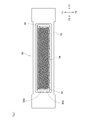
- FIG. 2 is a view showing a state in which the nozzle ejection surface 52 for ejecting paint is viewed from the front of the nozzle head unit 50.
- the nozzle ejection surface 52 is provided with a plurality of nozzle rows 55 in which the nozzles 54 are connected in a direction in which the nozzles 54 are inclined with respect to the width direction of the nozzle head unit 50.
- the nozzle row 55 includes a first nozzle row 55A existing on one side (Y2 side) in the main scanning direction (Y direction) and a second nozzle row existing on the other side in the main scanning direction. 55B (Y1 side) is provided.
- the droplets ejected from the nozzles 54 in the second nozzle row 55B are landed between the droplets ejected from the adjacent nozzles 54 in the first nozzle row 55A.
- the drive timing of the nozzle 54 is controlled. Thereby, the dot density can be improved at the time of painting.
- a single nozzle head 53 exists on the nozzle discharge surface 52.
- the nozzle discharge surface 52 may have a head group composed of a plurality of nozzle heads 53.
- a configuration in which a plurality of nozzle heads 53 are arranged in a staggered pattern while being aligned is mentioned, but the arrangement of the nozzle heads 53 in the head group does not have to be staggered. ..
- FIG. 4 is a diagram showing a schematic configuration for supplying paint to each nozzle 54.
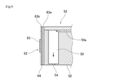
- FIG. 5 is a cross-sectional view showing a configuration in the vicinity of the row direction supply flow path 58, the nozzle pressurizing chamber 59, and the row direction discharge flow path 60.
- the nozzle head 53 includes a supply-side large flow path 57, a row-direction supply flow path 58, a nozzle pressurizing chamber 59, a row-direction discharge flow path 60, and a discharge-side large flow path. It is equipped with a road 61.
- the supply-side large flow path 57 is a flow path to which paint is supplied from the supply path 71 of the head-side circulation path described later.
- the row-direction supply flow path 58 is a flow path through which the paint in the supply-side large flow path 57 is diverted.
- the nozzle pressurizing chamber 59 is connected to the row direction supply flow path 58 via the nozzle supply flow path 59a. As a result, the paint is supplied to the nozzle pressurizing chamber 59 from the column direction supply flow path 58.
- the nozzle pressurizing chamber 59 is provided according to the number of nozzles 54, and the paint inside can be discharged from the nozzles 54 by using a drive element described later.
- the nozzle pressurizing chamber 59 is connected to the row direction discharge flow path 60 via a nozzle discharge flow path (not shown). Therefore, the paint that is not discharged from the nozzle 54 is discharged from the nozzle pressurizing chamber 59 to the row direction discharge flow path 60 via the nozzle discharge flow path 59b.
- the row direction discharge flow path 60 is connected to the discharge side large flow path 61.
- the discharge-side large flow path 61 is a flow path in which the paint discharged from each row-direction discharge flow path 60 merges.
- the discharge-side large flow path 61 is connected to the return path 72 of the head-side circulation path.
- the paint supplied from the supply path 71 of the head-side circulation path passes through the supply-side large flow path 57, the column direction supply flow path 58, the nozzle supply flow path 59a, and the nozzle pressurizing chamber 59, and the nozzle. It is discharged from 54. Further, the paint not discharged from the nozzle 54 passes from the nozzle pressurizing chamber 59 through the nozzle discharge flow path 59b, the row direction discharge flow path 60, and the discharge side large flow path 61 to the return path 72 of the head side circulation path. Will be returned.
- one row direction supply flow path 58 is arranged so as to correspond to one row direction discharge flow path 60.
- a plurality of (for example, two) row-direction discharge flow paths 60 may be arranged so as to correspond to one row-direction supply flow path 58.
- one row direction discharge flow path 60 may be arranged so as to correspond to the plurality of row direction supply flow paths 58.
- the piezoelectric substrate 62 is arranged on the top surface (the surface opposite to the nozzle 54) of the nozzle pressurizing chamber 59.
- the piezoelectric substrate 62 includes two piezoelectric ceramic layers 63a and 63b, which are piezoelectric bodies, and further includes a common electrode 64 and an individual electrode 65.
- the piezoelectric ceramic layers 63a and 63b are members that can be expanded and contracted by applying a voltage from the outside.
- piezoelectric ceramic layers 63a and 63b ceramic materials such as lead zirconate titanate (PZT), NaNbO3, BaTIO3, (BiNa) NbO3, and BiNaNb5O15, which have ferroelectricity, can be used. can.
- PZT lead zirconate titanate
- NaNbO3, BaTIO3, (BiNa) NbO3, and BiNaNb5O15 which have ferroelectricity
- the common electrode 64 is arranged between the piezoelectric ceramic layer 63a and the piezoelectric ceramic layer 63b. Further, a surface electrode (not shown) for a common electrode is formed on the upper surface of the piezoelectric substrate 62. The common electrode 64 and the surface electrode for the common electrode are electrically connected to each other through a through conductor (not shown) existing in the piezoelectric ceramic layer 63a. Further, the individual electrodes 65 are arranged at portions facing the nozzle pressurizing chamber 59. Further, in the piezoelectric ceramic layer 63a, the portion sandwiched between the common electrode 64 and the individual electrode 65 is polarized in the thickness direction.
- the piezoelectric ceramic layer 63a is distorted due to the piezoelectric effect. Therefore, when a predetermined drive signal is applied to the individual electrodes 65, the piezoelectric ceramic layer 63b relatively fluctuates so as to reduce the volume of the nozzle pressurizing chamber 59, whereby the paint is discharged.
- the common electrode 64 is arranged on the top surface of the nozzle pressurizing chamber 59, but the configuration is not limited to this.
- the common electrode 64 may adopt a configuration arranged on the side surface of the nozzle pressurizing chamber 59, and if the paint can be satisfactorily ejected from the nozzle 54, what is the case? May be adopted.
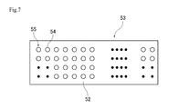
- FIG. 7 is a plan view showing the configuration of the nozzle discharge surface 52 of another nozzle head unit.
- a plurality of nozzles 54 may be arranged along the lateral direction (width direction; Y direction) of the nozzle head 53 to form the nozzle row 55.
- a plurality of nozzles 54 are arranged side by side in the lateral direction (width direction; main scanning direction) of the nozzle head 53 to form a nozzle row 55, but one (single) nozzle.
- Only 54 may be arranged in the lateral direction (width direction; main scanning direction) of the nozzle head 53. That is, the nozzle row 55 may be composed of one nozzle 54.
- the longitudinal direction of the nozzle head 53 is set with respect to the main scanning direction of the nozzle head 53. It may be tilted by an angle ⁇ . In the case of tilting in this way, it is possible to realize the same coating as the nozzle head 53 shown in FIG. 2 only by adjusting the ejection timing of the paint from each nozzle 54.
- FIG. 8 is a cross-sectional view showing the configuration of the nozzle head unit 50.
- FIG. 9 is a block diagram showing an electrical configuration in the vicinity of the nozzle head unit 50. As shown in FIGS. 8 and 9, the nozzle head unit 50 has an explosion-proof housing 70.
- the explosion-proof housing 70 has an internal space P1 sealed from the external atmosphere, and the internal pressure of the internal space P1 is increased by supplying an inert gas from the gas supply joint 81 (internal pressure of the internal space P1). Is higher than the pressure of the external atmosphere), and adopts an internal pressure explosion-proof structure. Further, in the explosion-proof housing 70, the internal space P1 is sealed so as not to cause ignition to the external atmosphere through all the joints and openings that isolate the internal space P1. Further, by maintaining the pressure of the non-flammable inert gas in the internal space P1 higher than the pressure of the external atmosphere, the flammable pressurizing gas in the external atmosphere can be prevented from entering the internal space P1. I'm preventing it. The explosion-proof performance of the explosion-proof housing 70 is ensured even by such a configuration for increasing the internal pressure.
- the explosion-proof housing 70 has a tubular portion 71 that covers the above-mentioned internal space P1, a bulging portion 72, and a front cover 73.
- the tubular portion 71 is a portion provided in a cylindrical shape (for example, a rectangular tubular shape) in which portions having the same width (cross-sectional area) are continuous.
- the width (cross-sectional area) of the tubular portion 71 may be partially different.
- the tubular portion 71 includes various shapes such as a rectangular housing and a cylindrical housing.
- the bulging portion 72 is a portion having a portion having a width (cross-sectional area) bulging more than the tubular portion 71, and the nozzle head 53 is arranged in the bulging portion 72 by utilizing such a bulge. ing.
- the front cover 73 is attached to the opening side of the bulging portion 72. That is, the front cover 73 is attached to the opening portion of the explosion-proof housing 70 away from the wrist portion 27.
- the nozzle head 53 is attached via the front cover 73. That is, the front cover 73 is provided with a mounting opening (not shown), and the nozzle head 53 is mounted on the front cover 73 with the nozzle discharge surface 52 of the nozzle head 53 exposed from the mounting opening. Has been done.
- the explosion-proof housing 70 is provided with a gas introduction port 74, and a gas supply joint 81 is attached to the gas introduction port 74.
- the gas introduction port 74 is provided on the bulging outer peripheral wall 72a of the bulging portion 72 described above.
- the bulging outer peripheral wall 72a is a wall surface facing the nozzle head 53 in FIG.
- the bulging outer peripheral wall 72a is a wall surface that does not face parallel to the top surface of the nozzle head 53 but faces at a predetermined angle, but faces parallel to the top surface of the nozzle head 53. It may be formed as follows.
- the gas supply joint 81 corresponds to the gas supply means, at least one of the pressurizing pipe line 83 and the pressurizing means 84 other than the gas supply joint 81 may also correspond to the gas supply means.
- the gas supply joint 81 can inject the inert gas toward the nozzle head 53.
- the inert gas is maintained at a temperature sufficiently lower than that of the heat sink 90 described later.
- a pressurizing pipe line 83 as shown in FIG. 9 is connected to the gas supply joint 81, and a pressurizing means 84 such as a compressor is connected to the pressurizing pipe line 83.
- the gas introduction port 74 is arranged in the vicinity of the nozzle head 53 in FIG. 8, and can supply the inert gas toward the nozzle head 53.
- the explosion-proof housing 70 is provided with a gas discharge port 75.
- a gas control valve 82 such as a proportional control valve is attached to the gas discharge port 75. Further, the gas control valve 82 corresponds to the gas discharge means. The gas control valve 82 makes it possible to adjust the flow rate at which the inert gas is discharged to adjust the pressure in the internal space P1.
- the gas control valve 82 is attached to the wall surface of the explosion-proof housing 70 on the side opposite to the gas supply joint 81 with the nozzle head 53 interposed therebetween in the internal space P1 of the explosion-proof housing 70.
- FIG. 8 shows a case where the gas control valve 82 is mounted closer to the ceiling surface 76 away from the nozzle discharge surface 52 than the center of the internal space P1.
- the mounting position of the gas control valve 82 is not limited to this, and any position is provided on the wall surface of the explosion-proof housing 70 on the opposite side of the nozzle head 53 from the gas supply joint 81. It may be.
- the gas control valve 82 may be attached to the wall surface of the explosion-proof housing 70 on the same side as the gas supply joint 81 with respect to the nozzle head 53. ..
- a heat sink 90 is attached to the nozzle head 53.
- the heat radiating plate 90 is attached to the side surface 53a of the nozzle head 53, which is a surface intersecting the nozzle discharge surface 52. As a result, the heat generated from the nozzle head 53 can be dissipated over a relatively large area.
- the heat radiating plate 90 corresponds to the heat radiating means.
- each side surface 53a it is preferable to attach a heat sink 90 to each side surface 53a, but if one heat sink 90 can provide sufficient heat dissipation performance, the two side surfaces 53a It may be attached to only one of the surfaces. Further, the heat sink 90 may be attached to the top surface 53b on the side opposite to the nozzle discharge surface 52.
- the heat radiating plate 90 is made of an aluminum-based metal which is superior in thermal conductivity and workability to iron or the like, but copper, which is superior in thermal conductivity to aluminum-based metal, may be used as a material. Further, in order to increase the surface area of the heat radiating plate 90, a configuration having a large number of fins may be used.
- a temperature sensor 100 is attached to the heat sink 90, and the temperature of the heat sink 90 is measured by the temperature sensor 100.
- the temperature sensor 100 include a PTC (Positive Temperature Coefficient) thermistor, an NTC (Negative Temperature Coefficient) thermistor, a thermocouple, an RTD (Resistance Temperature Detector), and a semiconductor temperature sensor.
- the temperature sensor 100 corresponds to the temperature measuring means.
- the temperature sensor 100 is connected to the circuit breaker 110 outside the explosion-proof housing 70 via a signal line (not shown).
- the circuit breaker 110 cuts off the supply of electric power to the nozzle head 53, and is a power line before and after the power supply circuit 120 that supplies electric power for driving to the drive driver 170 described later (nozzle head in FIG. 9). It is attached to the main control unit 130 side away from 53).
- the power supply circuit 120 corresponds to the power supply means.
- the circuit breaker 110 corresponds to the power cutoff means.
- the circuit breaker 110 When the temperature sensor 100 detects that the temperature of the nozzle head 53 (heat sink 90) is equal to or higher than the specified temperature, the circuit breaker 110 operates and the power supply to the nozzle head 53 is forcibly stopped. Be made to. This prevents the nozzle head 53 from rising above the specified temperature.
- the painting robot 10 is provided with a main control unit 130, and the main control unit 130 cooperates with each part of the painting robot 10 to perform painting on an object to be painted.
- a predetermined control signal is transmitted to the head control unit 140, the valve control unit 150, and the pressurizing means control unit 160.
- the main control unit 130 and the valve control unit 150 constitute control means, but at least one of the main control unit 130, the valve control unit 150, and the pressurizing means control unit 160 may constitute the control means.
- the circuit breaker 110 described above is arranged between the main control unit 130 and the power supply circuit 120. Therefore, when the circuit breaker 110 is activated, the power supply to the power supply circuit 120 is forcibly stopped, so that power is not supplied to the drive driver 170 for driving the nozzle head 53. Therefore, the drive of the piezoelectric substrate 62 is stopped.
- a control means different from the configuration shown in FIG. 9 may be configured.
- the circuit breaker 110 described above is arranged between the main control unit 130 and the head control unit 140, between the power supply circuit 120 and the drive driver 170, and between the head control unit 140 and the drive driver 170. The configuration may be adopted.
- the main control unit 130, the head control unit 140, the valve control unit 150, and the pressurizing means control unit 160 are composed of a CPU, a memory (ROM, RAM, non-volatile memory, etc.), and other elements.
- the memory stores programs and data for executing desired control.
- the head control unit 140 transmits a control signal related to the image to the drive driver 170 based on the command from the main control unit 130.
- the valve control unit 150 is a unit that controls the operation of the gas control valve 82 based on a command from the main control unit 130.
- the pressurizing means control unit 160 is a portion that controls the operation of the pressurizing means 84 based on a command from the main control unit 130.
- the drive driver 170 is a part that controls the application of electric power for driving the piezoelectric substrate 62 in the nozzle head 53 based on a command from the head control unit 140.
- the heat sink 90 is attached to the nozzle head 53. Therefore, the heat generated by the nozzle head 53 is released from the heat sink 90 to the internal space P1. Inert gas is supplied to the internal space P1 from the gas supply joint 81. Moreover, the gas supply joint 81 is attached to the bulging outer peripheral wall 72a, and the inert gas is injected toward the heat radiating plate 90. Therefore, the heat sink 90 is in a state where it is easily cooled by the inert gas.
- the inert gas in the internal space P1 is discharged from the gas control valve 82 attached to the gas discharge port 75.
- the valve control unit 150 controls the gas control valve 82 to adjust the flow rate of the inert gas discharged from the internal space P1.
- the pressure of the internal space P1 is adjusted to be higher than the pressure of the external atmosphere, for example.
- a temperature sensor 100 is attached to the heat sink 90, and the temperature of the heat sink 90 is measured by the temperature sensor 100. Then, when the temperature measured by the temperature sensor 100 reaches a temperature (specified temperature) that is not suitable for driving the nozzle head 53, a detection signal indicating that the specified temperature has been reached is transmitted to the circuit breaker 110. Then, the circuit breaker 110 immediately cuts off the power supply to the power supply circuit 120. As a result, the drive of the nozzle head 53 is forcibly stopped.
- the above specified temperature is higher than the temperature of the external atmosphere, but the temperature can be set in various ways. As an example, there are 125 degrees, 120 degrees, 100 degrees, and 80 degrees. Further, the specified temperature may be set to a temperature other than these temperatures.
- the inkjet coating robot 10 having the above configuration includes a plurality of nozzles 54, and supplies power to drive the nozzle head 53 for ejecting paint from the nozzles 54 by driving the piezoelectric substrate 62 and the piezoelectric substrate 62. It is provided with a power supply means (power supply circuit 120) to be mounted, and a robot arm R1 capable of mounting the nozzle head 53 on the tip portion and moving the mounted nozzle head 53.
- a power supply means power supply circuit 120
- the nozzle head 53 is covered with a portion other than the nozzle discharge surface 52 in a state where the nozzle discharge surface 52 is exposed to the outside, and the external atmosphere is prevented by preventing damage even if an explosion occurs in the internal space P1. It is provided in an explosion-proof housing 70 having an explosion-proof structure for preventing ignition of the nozzle. Further, in the explosion-proof housing 70, a heat radiating means (heat radiating plate 90) that dissipates heat generated from the nozzle head 53 is attached to the nozzle head 53, and in the explosion-proof housing 70, the temperature of the heat radiating means (heat radiating plate 90). A temperature measuring means (temperature sensor 100) for measuring the temperature is attached to the heat radiating means (heat radiating plate 90).
- a power cutoff means (circuit breaker 110) that cuts off the supply of power from the power supply means (power supply circuit 120) to the piezoelectric substrate 62, and the temperature measuring means (temperature sensor 100) reaches a specified temperature.
- the power cutoff means (circuit breaker 110) cuts off the power supply to the power supply means (power supply circuit 120) based on the detection signal from the temperature measuring means (temperature sensor 100).
- the temperature measuring means temperature sensor 100
- the heat radiating means heat radiating plate 90
- the temperature measuring means temperature sensor 100
- the power cutoff means cuts off the power supply to the power supply means (power supply circuit 120). Therefore, it is possible to suppress the temperature rise of the nozzle head 53 to a specified temperature or less (constant temperature or less). Therefore, in the nozzle head 53, it is possible to prevent an abnormal temperature rise.
- the nozzle head 53 is equipped with a heat radiating means (heat radiating plate 90), it is possible to suppress the temperature rise in the internal space P1.
- the nozzle head 53 is arranged in the internal space P1 of the explosion-proof housing 70, it is possible to isolate the portion where the temperature rises remarkably from the external atmosphere. Therefore, even if an explosion occurs in the internal space P1 or a spark or the like occurs in an electrically driven portion such as the piezoelectric substrate 62, it is possible to prevent the influence from being generated in the external atmosphere.
- the explosion-proof housing 70 has an internal pressure explosion-proof structure in which the internal pressure of the internal space P1 is higher than the pressure of the external atmosphere. With such a configuration, it is possible to satisfactorily prevent the external atmosphere from flowing into the internal space P1. Thereby, the explosion-proof performance of the explosion-proof housing 70 can be improved.
- the heat radiating means is a heat radiating plate 90, and the heat radiating plate 90 is attached to the side surface 53a of the nozzle head 53 that intersects the nozzle discharge surface 52.
- the explosion-proof housing 70 includes a gas supply means (gas supply joint 81) attached to the gas introduction port 74 formed in the explosion-proof housing 70 and a gas discharge port 75 formed in the explosion-proof housing 70. It is equipped with a gas discharge means (gas control valve 82) attached to the housing. Then, the inert gas is introduced from the gas introduction port 74, and the inert gas is discharged from the gas discharge means (gas control valve 82).
- the inert gas is supplied from the gas supply means (gas supply joint 81) to the internal space P1 of the explosion-proof housing 70, and the inert gas is used as the gas discharge means (gas control valve 82). ) Is discharged. Therefore, the inert gas can be circulated inside the internal space P1 and the heat radiated from the heat radiating means (heat radiating plate 90) can be satisfactorily discharged to the outside. As a result, the cooling performance of the nozzle head 53 can be further improved.
- the explosion-proof housing 70 is provided with a tubular portion 71 and a bulging portion 72 having a larger width direction than the outer peripheral surface of the tubular portion 71.
- the gas supply means (gas supply joint 81) is attached to the bulging outer peripheral wall 72a facing the heat radiating means (heat radiating plate 90) in the bulging portion 72, so that the gas supply means (gas supply joint 81) is directed toward the radiating means (heat radiating plate 90).
- the gas supply means (gas supply joint 81) injects the inert gas.
- the tubular portion 71 has a narrower width and a smaller cross-sectional area than the bulging portion 72, so that the weight of the explosion-proof material (metal, resin, etc.) used for the tubular portion 71 can be reduced. Can be reduced. Therefore, the behavior of the robot arm R1 can be improved. Further, since the gas introduction port 74 can be formed on the bulging outer peripheral wall 72a of the bulging portion 72 due to the presence of the bulging portion 72, the heat radiating means (heat radiating plate 90) is formed from the gas supply means (gas supply joint 81). A fresh inert gas (whose temperature is relatively lower than the interior space P1) can be injected toward. Thereby, the cooling performance of the nozzle head 53 can be improved.
- the gas supply means gas supply joint 81
- the gas discharge means is a gas control valve 82 capable of adjusting the flow rate of the inert gas, and the gas control valve 82 sandwiches the nozzle head 53 in the internal space P1 of the explosion-proof housing 70. It is attached to the wall surface of the explosion-proof housing 70 on the opposite side of the gas supply joint 81.
- the inert gas introduced from the gas supply means can be circulated in the internal space P1. Therefore, it is possible to prevent the fresh (temperature relatively lower than the internal space P1) inert gas from being immediately discharged to the outside. Therefore, the inert gas can be effectively utilized for lowering the temperature of the nozzle head 53, and the nozzle head 53 can be cooled more satisfactorily.
- the operation of the gas control valve 82 is controlled, and the flow rate of the inert gas discharged from the gas control valve 82 is controlled so that the internal pressure of the internal space P1 becomes higher than the pressure of the external atmosphere. It has a control means (valve control unit 150).
- the internal pressure of the internal space P1 can be made higher than that of the external atmosphere, so that it is possible to better prevent the external atmosphere from flowing into the internal space P1.
- the explosion-proof performance of the explosion-proof housing 70 can be further improved by enhancing the inside of the internal space P1.
- the heat sink 90 is described as the heat dissipation means.
- the heat dissipation means is not limited to the heat sink 90.
- the heat radiating means may be a cooling fan for forcibly flowing an inert gas, a water cooling mechanism for cooling the nozzle head 53 with cold water, a Pertier element, or the like, instead of the heat radiating plate 90 or together with the heat radiating plate 90. Is also good.
- the internal pressure of the internal space P1 is made higher than that of the external atmosphere by adjusting the flow rate of the inert gas discharged from the gas control valve 82.
- the internal pressure of the internal space P1 may be controlled to be higher than the external atmosphere.
- the temperature sensor 100 is attached to the heat radiating plate 90 corresponding to the heat radiating means.
- the temperature sensor 100 may be attached to a nozzle head 53 other than the heat sink 90 and a member fixed to the nozzle head 53.
- the explosion-proof housing 70 adopts an internal pressure explosion-proof structure as the explosion-proof structure.
- the explosion-proof structure in the explosion-proof housing 70 may be an explosion-proof structure other than the internal pressure explosion-proof structure.
- the explosion-proof housing 70 may adopt a pressure-resistant explosion-proof structure made of a pressure-resistant material, may adopt a safety-enhanced explosion-proof structure, or may adopt another explosion-proof structure.
- Nozzle pressurizing chamber 59a ... Nozzle supply flow path, 59b ... Nozzle discharge flow path, 60 ... Column direction discharge flow path, 61 ... Discharge side large flow path, 62 ... Hydraulic substrate, 63a ... Common electrode, 65 ... Individual electrode, 70 ... Explosion-proof housing, 71 ... Supply path, 71 ... Cylindrical part, 72 ... Return path, 72 ... Swelling part, 72a ... Swelling outer wall, 73 ... Front cover, 74 ... Gas Introductory port, 75 ... Gas discharge port, 76 ... Ceiling surface, 81 ... Gas supply joint (corresponding to gas supply means), 82 ... Gas control valve (corresponding to gas discharge means), 83 ...
Landscapes
- Engineering & Computer Science (AREA)
- Robotics (AREA)
- Mechanical Engineering (AREA)
- Human Computer Interaction (AREA)
- Manipulator (AREA)
- Spray Control Apparatus (AREA)
Abstract
La présente invention concerne une machine de peinture de véhicule de type jet d'encre capable de maintenir l'élévation de température d'une tête de buse jusqu'à une certaine température ou moins. Le robot de peinture (10) comprend un moyen d'alimentation en énergie (120) destiné à l'alimentation en énergie pour entraîner un substrat piézoélectrique (62) d'une tête de buse (53), et un bras de robot (R1) destiné à déplacer la tête de buse (53). La tête de buse (53) est disposée dans un logement anti-déflagration (70) équipé d'une construction anti-déflagration. Un moyen de dissipation de chaleur (90) qui dissipe la chaleur générée de la tête de buse (53) à l'intérieur du logement anti-déflagration (70) est fixé à la tête de buse (53). Un moyen de mesure de température (100) pour mesurer la température du moyen de dissipation de chaleur (90) est fixé au moyen de dissipation de chaleur (90). L'invention concerne également un moyen de coupure d'alimentation (110) pour couper l'alimentation en énergie du moyen d'alimentation d'énergie (120) au substrat piézoélectrique (62) en fonction d'un signal de détection provenant du moyen de mesure de température (100) lorsque le moyen de mesure de température (100) mesure qu'une température stipulée a été atteinte.
Priority Applications (5)
| Application Number | Priority Date | Filing Date | Title |
|---|---|---|---|
| EP20942912.5A EP4173723A4 (fr) | 2020-06-29 | 2020-06-29 | Robot de peinture |
| CN202080065069.6A CN114401795B (zh) | 2020-06-29 | 2020-06-29 | 涂装机器人 |
| PCT/JP2020/025473 WO2022003759A1 (fr) | 2020-06-29 | 2020-06-29 | Robot de peinture |
| US17/753,811 US11701678B1 (en) | 2020-06-29 | 2020-06-29 | Painting robot |
| JP2022533263A JP7231790B2 (ja) | 2020-06-29 | 2020-06-29 | 塗装ロボット |
Applications Claiming Priority (1)
| Application Number | Priority Date | Filing Date | Title |
|---|---|---|---|
| PCT/JP2020/025473 WO2022003759A1 (fr) | 2020-06-29 | 2020-06-29 | Robot de peinture |
Publications (1)
| Publication Number | Publication Date |
|---|---|
| WO2022003759A1 true WO2022003759A1 (fr) | 2022-01-06 |
Family
ID=79315752
Family Applications (1)
| Application Number | Title | Priority Date | Filing Date |
|---|---|---|---|
| PCT/JP2020/025473 WO2022003759A1 (fr) | 2020-06-29 | 2020-06-29 | Robot de peinture |
Country Status (5)
| Country | Link |
|---|---|
| US (1) | US11701678B1 (fr) |
| EP (1) | EP4173723A4 (fr) |
| JP (1) | JP7231790B2 (fr) |
| CN (1) | CN114401795B (fr) |
| WO (1) | WO2022003759A1 (fr) |
Citations (8)
| Publication number | Priority date | Publication date | Assignee | Title |
|---|---|---|---|---|
| JPS6078658A (ja) * | 1983-10-07 | 1985-05-04 | Mitsubishi Heavy Ind Ltd | 電動式塗装ロボツト |
| JPH0672652U (ja) * | 1993-03-26 | 1994-10-11 | トリニティ工業株式会社 | ロボット塗装装置 |
| JPH0890471A (ja) * | 1994-09-19 | 1996-04-09 | Suzuki Motor Corp | 工業用ロボット |
| JPH10230200A (ja) * | 1997-02-20 | 1998-09-02 | Tokico Ltd | 塗装用ロボット |
| JP2008514504A (ja) * | 2004-09-30 | 2008-05-08 | アーベーベー アーエス | 産業用ロボットに使用されるドア開閉機構 |
| JP2015036127A (ja) * | 2013-08-12 | 2015-02-23 | トヨタ自動車九州株式会社 | 塗装装置 |
| JP2017035693A (ja) | 2008-10-24 | 2017-02-16 | デュール システムズ アーゲーDurr Systems AG | 塗装機器および塗装方法 |
| JP2018502702A (ja) | 2014-12-01 | 2018-02-01 | デュール システムズ アーゲーDurr Systems AG | コーティング法と対応するコーティング設備 |
Family Cites Families (12)
| Publication number | Priority date | Publication date | Assignee | Title |
|---|---|---|---|---|
| US20030155434A1 (en) * | 2002-02-01 | 2003-08-21 | Rini Daniel P. | Spray nozzle apparatus and method of use |
| JP2011016319A (ja) | 2009-07-10 | 2011-01-27 | Fujifilm Corp | 圧電装置、圧電素子の駆動方法、及び液体吐出装置 |
| JP5967350B2 (ja) | 2012-01-24 | 2016-08-10 | セイコーエプソン株式会社 | 液体噴射ヘッドモジュール及び液体噴射装置 |
| KR101461738B1 (ko) | 2012-12-21 | 2014-11-14 | 주식회사 포스코 | 가열장치 및 이를 포함하는 코팅 시스템 |
| JP6270896B2 (ja) | 2016-03-29 | 2018-01-31 | 本田技研工業株式会社 | 塗装ノズル及び塗装装置並びにそれらを用いた塗装方法 |
| WO2017183389A1 (fr) | 2016-04-18 | 2017-10-26 | コニカミノルタ株式会社 | Tête à jet d'encre, module de tête et dispositif d'enregistrement à jet d'encre |
| DE102016014943A1 (de) * | 2016-12-14 | 2018-06-14 | Dürr Systems Ag | Druckkopf mit Temperiereinrichtung |
| JP2019010695A (ja) * | 2017-06-29 | 2019-01-24 | 株式会社安川電機 | ロボット |
| CN107471638A (zh) | 2017-07-18 | 2017-12-15 | 葛顺英 | 一种节能型3d打印设备 |
| DE102017122492A1 (de) * | 2017-09-27 | 2019-03-28 | Dürr Systems Ag | Applikator mit einer integrierten Steuerschaltung |
| JP2019206051A (ja) * | 2018-05-29 | 2019-12-05 | 川崎重工業株式会社 | 掃気装置及びそれを備えるロボットシステム並びに掃気方法 |
| WO2020128823A1 (fr) * | 2018-12-19 | 2020-06-25 | 3M Innovative Properties Company | Système de revêtement automatisé ayant un outil d'organe terminal effecteur intelligent |
-
2020
- 2020-06-29 WO PCT/JP2020/025473 patent/WO2022003759A1/fr unknown
- 2020-06-29 US US17/753,811 patent/US11701678B1/en active Active
- 2020-06-29 CN CN202080065069.6A patent/CN114401795B/zh active Active
- 2020-06-29 JP JP2022533263A patent/JP7231790B2/ja active Active
- 2020-06-29 EP EP20942912.5A patent/EP4173723A4/fr active Pending
Patent Citations (8)
| Publication number | Priority date | Publication date | Assignee | Title |
|---|---|---|---|---|
| JPS6078658A (ja) * | 1983-10-07 | 1985-05-04 | Mitsubishi Heavy Ind Ltd | 電動式塗装ロボツト |
| JPH0672652U (ja) * | 1993-03-26 | 1994-10-11 | トリニティ工業株式会社 | ロボット塗装装置 |
| JPH0890471A (ja) * | 1994-09-19 | 1996-04-09 | Suzuki Motor Corp | 工業用ロボット |
| JPH10230200A (ja) * | 1997-02-20 | 1998-09-02 | Tokico Ltd | 塗装用ロボット |
| JP2008514504A (ja) * | 2004-09-30 | 2008-05-08 | アーベーベー アーエス | 産業用ロボットに使用されるドア開閉機構 |
| JP2017035693A (ja) | 2008-10-24 | 2017-02-16 | デュール システムズ アーゲーDurr Systems AG | 塗装機器および塗装方法 |
| JP2015036127A (ja) * | 2013-08-12 | 2015-02-23 | トヨタ自動車九州株式会社 | 塗装装置 |
| JP2018502702A (ja) | 2014-12-01 | 2018-02-01 | デュール システムズ アーゲーDurr Systems AG | コーティング法と対応するコーティング設備 |
Non-Patent Citations (1)
| Title |
|---|
| See also references of EP4173723A4 |
Also Published As
| Publication number | Publication date |
|---|---|
| JPWO2022003759A1 (fr) | 2022-01-06 |
| CN114401795A (zh) | 2022-04-26 |
| EP4173723A1 (fr) | 2023-05-03 |
| CN114401795B (zh) | 2023-05-26 |
| US11701678B1 (en) | 2023-07-18 |
| JP7231790B2 (ja) | 2023-03-01 |
| EP4173723A4 (fr) | 2024-03-27 |
| US20230211367A1 (en) | 2023-07-06 |
Similar Documents
| Publication | Publication Date | Title |
|---|---|---|
| US6074043A (en) | Spray device for ink-jet printer having a multilayer membrane for ejecting ink | |
| US7997695B2 (en) | Liquid ejecting head, liquid ejecting apparatus, and actuator | |
| US11845270B2 (en) | Ink-jet type vehicle coating machine and vehicle coating method | |
| WO2022003759A1 (fr) | Robot de peinture | |
| JP7285827B2 (ja) | 塗装機および塗装方法 | |
| CN114555239A (zh) | 涂装机器人及使用涂装机器人的涂装方法 | |
| US20090058968A1 (en) | Inkjet print head and method of printing therewith | |
| US7168791B2 (en) | Piezoelectric ink jet printing module | |
| TW201603890A (zh) | 液體噴出裝置及液體噴出方法 | |
| JP6790506B2 (ja) | 液体吐出装置 | |
| JP2009262421A (ja) | インクジェットヘッドおよびインクジェット式記録装置 | |
| JP2004509783A5 (fr) | ||
| US20050225598A1 (en) | Fluid ejection devices and operation thereof | |
| US10173422B2 (en) | Liquid ejecting head and liquid ejecting apparatus | |
| JP2003291348A (ja) | インクジェット記録ヘッド、および非線形電気素子 | |
| JP4752834B2 (ja) | 重量測定方法、電気光学装置の製造方法及び半導体装置の製造方法 | |
| JP2006255994A (ja) | 液滴吐出装置及び液滴吐出方法 | |
| US7959265B2 (en) | Thermal inkjet printhead | |
| JP2831424B2 (ja) | インクジェット記録装置 | |
| JP2006228496A (ja) | 液滴吐出装置、液滴吐出方法、有機el装置の製造方法 | |
| JP4626196B2 (ja) | 液滴吐出装置、および電気光学装置の製造方法 | |
| KR20130039006A (ko) | 잉크젯 프린트 헤드 조립체 | |
| JPH0358850A (ja) | 液体噴射記録装置 | |
| US20200384773A1 (en) | Liquid ejection head | |
| JP3159272B2 (ja) | インクジェットプリントヘッド及びインクジェットプリンタ |
Legal Events
| Date | Code | Title | Description |
|---|---|---|---|
| 121 | Ep: the epo has been informed by wipo that ep was designated in this application |
Ref document number: 20942912 Country of ref document: EP Kind code of ref document: A1 |
|
| ENP | Entry into the national phase |
Ref document number: 2022533263 Country of ref document: JP Kind code of ref document: A |
|
| NENP | Non-entry into the national phase |
Ref country code: DE |
|
| ENP | Entry into the national phase |
Ref document number: 2020942912 Country of ref document: EP Effective date: 20230130 |