WO2022003759A1 - Painting robot - Google Patents
Painting robot Download PDFInfo
- Publication number
- WO2022003759A1 WO2022003759A1 PCT/JP2020/025473 JP2020025473W WO2022003759A1 WO 2022003759 A1 WO2022003759 A1 WO 2022003759A1 JP 2020025473 W JP2020025473 W JP 2020025473W WO 2022003759 A1 WO2022003759 A1 WO 2022003759A1
- Authority
- WO
- WIPO (PCT)
- Prior art keywords
- explosion
- nozzle head
- nozzle
- gas
- painting robot
- Prior art date
Links
- 238000010422 painting Methods 0.000 title claims abstract description 60
- 239000000758 substrate Substances 0.000 claims abstract description 23
- 238000001514 detection method Methods 0.000 claims abstract description 5
- 239000007789 gas Substances 0.000 claims description 97
- 239000011261 inert gas Substances 0.000 claims description 35
- 239000003973 paint Substances 0.000 claims description 31
- 230000002093 peripheral effect Effects 0.000 claims description 12
- 239000000463 material Substances 0.000 claims description 6
- 238000007599 discharging Methods 0.000 claims 1
- 230000017525 heat dissipation Effects 0.000 abstract description 10
- 238000009529 body temperature measurement Methods 0.000 abstract 3
- 238000010276 construction Methods 0.000 abstract 1
- 239000000919 ceramic Substances 0.000 description 9
- 210000000707 wrist Anatomy 0.000 description 9
- 239000011248 coating agent Substances 0.000 description 7
- 238000000576 coating method Methods 0.000 description 7
- 238000001816 cooling Methods 0.000 description 7
- 238000010586 diagram Methods 0.000 description 4
- 230000001965 increasing effect Effects 0.000 description 4
- 238000004880 explosion Methods 0.000 description 3
- 229910052751 metal Inorganic materials 0.000 description 3
- 239000002184 metal Substances 0.000 description 3
- XEEYBQQBJWHFJM-UHFFFAOYSA-N Iron Chemical compound [Fe] XEEYBQQBJWHFJM-UHFFFAOYSA-N 0.000 description 2
- 229910052782 aluminium Inorganic materials 0.000 description 2
- XAGFODPZIPBFFR-UHFFFAOYSA-N aluminium Chemical compound [Al] XAGFODPZIPBFFR-UHFFFAOYSA-N 0.000 description 2
- 238000000889 atomisation Methods 0.000 description 2
- 230000000694 effects Effects 0.000 description 2
- 230000020169 heat generation Effects 0.000 description 2
- 238000009434 installation Methods 0.000 description 2
- 229910052451 lead zirconate titanate Inorganic materials 0.000 description 2
- 239000003960 organic solvent Substances 0.000 description 2
- 230000008961 swelling Effects 0.000 description 2
- XLYOFNOQVPJJNP-UHFFFAOYSA-N water Substances O XLYOFNOQVPJJNP-UHFFFAOYSA-N 0.000 description 2
- RYGMFSIKBFXOCR-UHFFFAOYSA-N Copper Chemical compound [Cu] RYGMFSIKBFXOCR-UHFFFAOYSA-N 0.000 description 1
- 229910003378 NaNbO3 Inorganic materials 0.000 description 1
- 230000002159 abnormal effect Effects 0.000 description 1
- 230000006399 behavior Effects 0.000 description 1
- 229910010293 ceramic material Inorganic materials 0.000 description 1
- 239000004020 conductor Substances 0.000 description 1
- 229910052802 copper Inorganic materials 0.000 description 1
- 239000010949 copper Substances 0.000 description 1
- 230000002542 deteriorative effect Effects 0.000 description 1
- 230000002708 enhancing effect Effects 0.000 description 1
- 230000005621 ferroelectricity Effects 0.000 description 1
- 229910052742 iron Inorganic materials 0.000 description 1
- HFGPZNIAWCZYJU-UHFFFAOYSA-N lead zirconate titanate Chemical compound [O-2].[O-2].[O-2].[O-2].[O-2].[Ti+4].[Zr+4].[Pb+2] HFGPZNIAWCZYJU-UHFFFAOYSA-N 0.000 description 1
- 230000007257 malfunction Effects 0.000 description 1
- 238000004519 manufacturing process Methods 0.000 description 1
- 238000000034 method Methods 0.000 description 1
- 239000011347 resin Substances 0.000 description 1
- 229920005989 resin Polymers 0.000 description 1
- 230000000630 rising effect Effects 0.000 description 1
- 239000004065 semiconductor Substances 0.000 description 1
- MUPJWXCPTRQOKY-UHFFFAOYSA-N sodium;niobium(5+);oxygen(2-) Chemical compound [O-2].[O-2].[O-2].[Na+].[Nb+5] MUPJWXCPTRQOKY-UHFFFAOYSA-N 0.000 description 1
- 239000007921 spray Substances 0.000 description 1
- 230000009466 transformation Effects 0.000 description 1
Images


Classifications
-
- B—PERFORMING OPERATIONS; TRANSPORTING
- B05—SPRAYING OR ATOMISING IN GENERAL; APPLYING FLUENT MATERIALS TO SURFACES, IN GENERAL
- B05B—SPRAYING APPARATUS; ATOMISING APPARATUS; NOZZLES
- B05B15/00—Details of spraying plant or spraying apparatus not otherwise provided for; Accessories
-
- B—PERFORMING OPERATIONS; TRANSPORTING
- B05—SPRAYING OR ATOMISING IN GENERAL; APPLYING FLUENT MATERIALS TO SURFACES, IN GENERAL
- B05B—SPRAYING APPARATUS; ATOMISING APPARATUS; NOZZLES
- B05B1/00—Nozzles, spray heads or other outlets, with or without auxiliary devices such as valves, heating means
- B05B1/14—Nozzles, spray heads or other outlets, with or without auxiliary devices such as valves, heating means with multiple outlet openings; with strainers in or outside the outlet opening
-
- B—PERFORMING OPERATIONS; TRANSPORTING
- B05—SPRAYING OR ATOMISING IN GENERAL; APPLYING FLUENT MATERIALS TO SURFACES, IN GENERAL
- B05B—SPRAYING APPARATUS; ATOMISING APPARATUS; NOZZLES
- B05B12/00—Arrangements for controlling delivery; Arrangements for controlling the spray area
- B05B12/08—Arrangements for controlling delivery; Arrangements for controlling the spray area responsive to condition of liquid or other fluent material to be discharged, of ambient medium or of target ; responsive to condition of spray devices or of supply means, e.g. pipes, pumps or their drive means
-
- B—PERFORMING OPERATIONS; TRANSPORTING
- B05—SPRAYING OR ATOMISING IN GENERAL; APPLYING FLUENT MATERIALS TO SURFACES, IN GENERAL
- B05B—SPRAYING APPARATUS; ATOMISING APPARATUS; NOZZLES
- B05B13/00—Machines or plants for applying liquids or other fluent materials to surfaces of objects or other work by spraying, not covered by groups B05B1/00 - B05B11/00
- B05B13/02—Means for supporting work; Arrangement or mounting of spray heads; Adaptation or arrangement of means for feeding work
- B05B13/04—Means for supporting work; Arrangement or mounting of spray heads; Adaptation or arrangement of means for feeding work the spray heads being moved during spraying operation
- B05B13/0431—Means for supporting work; Arrangement or mounting of spray heads; Adaptation or arrangement of means for feeding work the spray heads being moved during spraying operation with spray heads moved by robots or articulated arms, e.g. for applying liquid or other fluent material to 3D-surfaces
-
- B—PERFORMING OPERATIONS; TRANSPORTING
- B05—SPRAYING OR ATOMISING IN GENERAL; APPLYING FLUENT MATERIALS TO SURFACES, IN GENERAL
- B05B—SPRAYING APPARATUS; ATOMISING APPARATUS; NOZZLES
- B05B15/00—Details of spraying plant or spraying apparatus not otherwise provided for; Accessories
- B05B15/14—Arrangements for preventing or controlling structural damage to spraying apparatus or its outlets, e.g. for breaking at desired places; Arrangements for handling or replacing damaged parts
-
- B—PERFORMING OPERATIONS; TRANSPORTING
- B25—HAND TOOLS; PORTABLE POWER-DRIVEN TOOLS; MANIPULATORS
- B25J—MANIPULATORS; CHAMBERS PROVIDED WITH MANIPULATION DEVICES
- B25J11/00—Manipulators not otherwise provided for
- B25J11/0075—Manipulators for painting or coating
-
- B—PERFORMING OPERATIONS; TRANSPORTING
- B25—HAND TOOLS; PORTABLE POWER-DRIVEN TOOLS; MANIPULATORS
- B25J—MANIPULATORS; CHAMBERS PROVIDED WITH MANIPULATION DEVICES
- B25J13/00—Controls for manipulators
- B25J13/08—Controls for manipulators by means of sensing devices, e.g. viewing or touching devices
- B25J13/087—Controls for manipulators by means of sensing devices, e.g. viewing or touching devices for sensing other physical parameters, e.g. electrical or chemical properties
-
- B—PERFORMING OPERATIONS; TRANSPORTING
- B25—HAND TOOLS; PORTABLE POWER-DRIVEN TOOLS; MANIPULATORS
- B25J—MANIPULATORS; CHAMBERS PROVIDED WITH MANIPULATION DEVICES
- B25J19/00—Accessories fitted to manipulators, e.g. for monitoring, for viewing; Safety devices combined with or specially adapted for use in connection with manipulators
- B25J19/0025—Means for supplying energy to the end effector
-
- B—PERFORMING OPERATIONS; TRANSPORTING
- B25—HAND TOOLS; PORTABLE POWER-DRIVEN TOOLS; MANIPULATORS
- B25J—MANIPULATORS; CHAMBERS PROVIDED WITH MANIPULATION DEVICES
- B25J19/00—Accessories fitted to manipulators, e.g. for monitoring, for viewing; Safety devices combined with or specially adapted for use in connection with manipulators
- B25J19/0054—Cooling means
-
- B—PERFORMING OPERATIONS; TRANSPORTING
- B25—HAND TOOLS; PORTABLE POWER-DRIVEN TOOLS; MANIPULATORS
- B25J—MANIPULATORS; CHAMBERS PROVIDED WITH MANIPULATION DEVICES
- B25J19/00—Accessories fitted to manipulators, e.g. for monitoring, for viewing; Safety devices combined with or specially adapted for use in connection with manipulators
- B25J19/0075—Means for protecting the manipulator from its environment or vice versa
- B25J19/0079—Means for protecting the manipulator from its environment or vice versa using an internal pressure system
-
- B—PERFORMING OPERATIONS; TRANSPORTING
- B25—HAND TOOLS; PORTABLE POWER-DRIVEN TOOLS; MANIPULATORS
- B25J—MANIPULATORS; CHAMBERS PROVIDED WITH MANIPULATION DEVICES
- B25J9/00—Programme-controlled manipulators
- B25J9/16—Programme controls
- B25J9/1674—Programme controls characterised by safety, monitoring, diagnostic
-
- B—PERFORMING OPERATIONS; TRANSPORTING
- B05—SPRAYING OR ATOMISING IN GENERAL; APPLYING FLUENT MATERIALS TO SURFACES, IN GENERAL
- B05B—SPRAYING APPARATUS; ATOMISING APPARATUS; NOZZLES
- B05B1/00—Nozzles, spray heads or other outlets, with or without auxiliary devices such as valves, heating means
- B05B1/02—Nozzles, spray heads or other outlets, with or without auxiliary devices such as valves, heating means designed to produce a jet, spray, or other discharge of particular shape or nature, e.g. in single drops, or having an outlet of particular shape
- B05B1/08—Nozzles, spray heads or other outlets, with or without auxiliary devices such as valves, heating means designed to produce a jet, spray, or other discharge of particular shape or nature, e.g. in single drops, or having an outlet of particular shape of pulsating nature, e.g. delivering liquid in successive separate quantities ; Fluidic oscillators
- B05B1/083—Nozzles, spray heads or other outlets, with or without auxiliary devices such as valves, heating means designed to produce a jet, spray, or other discharge of particular shape or nature, e.g. in single drops, or having an outlet of particular shape of pulsating nature, e.g. delivering liquid in successive separate quantities ; Fluidic oscillators the pulsating mechanism comprising movable parts
- B05B1/086—Nozzles, spray heads or other outlets, with or without auxiliary devices such as valves, heating means designed to produce a jet, spray, or other discharge of particular shape or nature, e.g. in single drops, or having an outlet of particular shape of pulsating nature, e.g. delivering liquid in successive separate quantities ; Fluidic oscillators the pulsating mechanism comprising movable parts with a resiliently deformable element, e.g. sleeve
-
- B—PERFORMING OPERATIONS; TRANSPORTING
- B05—SPRAYING OR ATOMISING IN GENERAL; APPLYING FLUENT MATERIALS TO SURFACES, IN GENERAL
- B05B—SPRAYING APPARATUS; ATOMISING APPARATUS; NOZZLES
- B05B15/00—Details of spraying plant or spraying apparatus not otherwise provided for; Accessories
- B05B15/50—Arrangements for cleaning; Arrangements for preventing deposits, drying-out or blockage; Arrangements for detecting improper discharge caused by the presence of foreign matter
- B05B15/58—Arrangements for cleaning; Arrangements for preventing deposits, drying-out or blockage; Arrangements for detecting improper discharge caused by the presence of foreign matter preventing deposits, drying-out or blockage by recirculating the fluid to be sprayed from upstream of the discharge opening back to the supplying means
-
- B—PERFORMING OPERATIONS; TRANSPORTING
- B05—SPRAYING OR ATOMISING IN GENERAL; APPLYING FLUENT MATERIALS TO SURFACES, IN GENERAL
- B05B—SPRAYING APPARATUS; ATOMISING APPARATUS; NOZZLES
- B05B17/00—Apparatus for spraying or atomising liquids or other fluent materials, not covered by the preceding groups
- B05B17/04—Apparatus for spraying or atomising liquids or other fluent materials, not covered by the preceding groups operating with special methods
- B05B17/06—Apparatus for spraying or atomising liquids or other fluent materials, not covered by the preceding groups operating with special methods using ultrasonic or other kinds of vibrations
- B05B17/0607—Apparatus for spraying or atomising liquids or other fluent materials, not covered by the preceding groups operating with special methods using ultrasonic or other kinds of vibrations generated by electrical means, e.g. piezoelectric transducers
- B05B17/0653—Details
- B05B17/0661—Transducer materials
Definitions
- the present invention relates to a painting robot.
- Patent Document 1 In the painting line of vehicles such as automobiles, robot painting using robots is the mainstream.
- a painting machine rotary atomization type painting machine
- Patent Document 2 discloses painting with a long spray pattern.
- the paint discharged from the nozzle of the nozzle head may change its characteristics such as viscosity due to heat, and the paint quality of the vehicle may deteriorate.
- some paints contain an organic solvent, it is not preferable that the temperature of the nozzle head rises significantly in a state where the paint containing such an organic solvent is discharged.
- the present invention has been made based on the above circumstances, and an object of the present invention is to provide a painting robot capable of suppressing a temperature rise of a nozzle head to a certain temperature or less.
- it is a painting robot for painting an object to be painted by ejecting paint from a nozzle, and is provided with a plurality of nozzles and is provided with a plurality of nozzles.
- a nozzle head that ejects paint from a nozzle by driving a piezoelectric substrate, a power supply means that supplies power to drive the piezoelectric substrate, and a robot that can attach the nozzle head to the tip and move the attached nozzle head.
- the nozzle head is provided with an arm and is provided in an explosion-proof housing that covers a portion other than the nozzle discharge surface in a state where the nozzle discharge surface is exposed to the outside, and is generated from the nozzle head in the explosion-proof housing.
- a heat radiating means for radiating heat is attached to the nozzle head, and in the explosion-proof housing, a temperature measuring means for measuring the temperature of the radiating means is attached to the radiating means, and the temperature measuring means has reached a specified temperature.
- a painting robot characterized by having a power cutoff means for cutting off the supply of power from the power supply means to the piezoelectric substrate based on a detection signal from the temperature measuring means when the fact is measured. Will be done.
- the explosion-proof housing has an internal pressure explosion-proof structure in which the internal pressure of the internal space is higher than the pressure of the external atmosphere.
- the explosion-proof housing has a pressure-resistant explosion-proof structure made of a pressure-resistant material.
- the heat radiating means is a heat radiating plate, and the radiating plate is attached to the side surface of the nozzle head that intersects the nozzle ejection surface.
- the explosion-proof housing includes a gas supply means attached to an air inlet formed in the explosion-proof housing and a gas discharge means attached to the gas discharge port formed in the explosion-proof housing. It is preferable that the inert gas is introduced from the gas supply means and the inert gas is discharged from the gas discharge means.
- the explosion-proof housing is provided with a cylindrical portion and a bulging portion whose width direction is larger than the outer peripheral surface of the tubular portion, and the gas supply means is expanded. It is preferable that the gas supply means injects the inert gas toward the heat dissipation means because it is attached to the bulging outer peripheral wall of the protrusion facing the heat dissipation means.
- the gas discharge means is a gas control valve capable of adjusting the flow rate of the inert gas
- the gas control valve is on the opposite side of the gas supply means with the nozzle head sandwiched in the internal space of the explosion-proof housing. It is preferably mounted on the wall of the explosion-proof housing.
- control means for controlling the operation of the gas control valve and controlling the flow rate of the inert gas discharged from the gas control valve so that the internal pressure in the internal space becomes higher than the pressure in the external atmosphere.
- the present invention it is possible to provide a painting robot capable of suppressing the temperature rise of the nozzle head to a certain temperature or less.
- FIG. 5 is a cross-sectional view showing a modified example of the configuration in the vicinity of the row direction supply flow path, the nozzle pressurizing chamber, and the row direction discharge flow path shown in FIG. FIG.
- FIG. 6 is a cross-sectional view showing a modified example of the configuration in the vicinity of the row direction supply flow path, the nozzle pressurizing chamber, and the row direction discharge flow path shown in FIG. It is a top view which shows the structure of the nozzle discharge surface in another nozzle head unit different from the nozzle head unit shown in FIG. It is sectional drawing which shows the structure of the nozzle head unit shown in FIG. It is a block diagram which shows the electric structure in the vicinity of the nozzle head unit shown in FIG.
- the X direction is the longitudinal direction of the nozzle discharge surface 52 (nozzle head 53), the X1 side is the right side in FIG. 2, and the X2 side is the left side in FIG.
- the Y direction is the lateral direction (width direction) of the nozzle ejection surface 52 (nozzle head 53), the Y1 side is the upper side of the paper surface in FIG. 2, and the Y2 side is the lower side of the paper surface in FIG.
- the painting robot of the present embodiment "paints" a vehicle or a vehicle part (hereinafter, a vehicle part that is a part of the vehicle is also described as a vehicle) located on a painting line in an automobile manufacturing factory.
- the purpose is to form a coating film on the surface of the object to be painted to protect the surface and give it an aesthetic appearance. Therefore, it is necessary to paint the vehicle moving along the painting line at predetermined time intervals with a desired painting quality within a certain time.
- the painting robot of the present embodiment it is possible not only to form the above-mentioned coating film but also to form various designs and images on the object to be painted such as a vehicle or a vehicle part.
- FIG. 1 is a schematic view showing the overall configuration of the painting robot 10 according to the first embodiment of the present invention. As shown in FIG. 1, the painting robot 10 has a robot main body 20 and a nozzle head unit 50 as main components.
- the robot main body 20 includes a base 21, legs 22, a rotating shaft 23, a rotating arm 24, a first rotating arm 25, a second rotating arm 26, and a list.
- the main components are a unit 27 and a motor (not shown) for driving them.
- the portion from the rotation shaft portion 23 to the wrist portion 27 corresponds to the robot arm R1, but other parts such as the leg portion 22 and the like may also correspond to the robot arm R1.
- the base 21 is a part that is installed at the installation site such as the floor surface, but the base 21 may be able to travel with respect to the installation site.
- the leg portion 22 is a portion erected from the base 21 toward the upper part.
- a joint portion may be provided between the leg portion 22 and the base 21 so that the leg portion 22 can rotate with respect to the base 21.
- a rotating shaft portion 23 is provided at the upper end of the leg portion 22.
- a rotary arm 24 is attached to the rotary shaft portion 23 in a rotatable state. Further, the rotary arm 24 is rotated by driving a motor (first motor), and as such a motor, an electric motor or an air motor can be used.
- first motor a motor
- an electric motor or an air motor can be used.
- explosion-proof measures such as increasing the internal pressure inside the housing of the rotating shaft portion 23 (adopting an internal pressure explosion-proof structure) (hereinafter,). The same applies to each of the motors (second motor to sixth motor).
- the explosion-proof structure near the nozzle head 53 will be described later.
- first rotating arm 25 is attached to the rotating arm 24 in a rotatable state.
- the second motor (not shown) that rotates the first rotation arm 25 relative to the rotation shaft portion 23 may be housed in the housing of the rotation arm 24, and the first rotation arm 25 may be housed in the housing. It may be stored in the housing of.
- one end side of the second rotating arm 26 is attached to the other end side of the first rotating arm 25 in a swingable state via a shaft portion.
- the third motor (not shown) that rotates the second rotation arm 26 relative to the first rotation arm 25 may be housed in the housing of the first rotation arm 25, and is the second. It may be housed in the housing of the rotating arm 26.
- a wrist portion 27 is attached to the other end side of the second rotating arm 26.
- the wrist portion 27 enables rotational movement around a plurality of (for example, three) shaft portions in different directions. As a result, it is possible to accurately control the orientation of the nozzle head unit 50.
- the number of shaft portions may be any number as long as it is two or more.
- Motors (4th to 6th motors; not shown) are provided in order to enable rotational movement around each shaft portion of the wrist portion 27.
- the fourth motor to the sixth motor are housed in the housing of the second rotating arm 26, they may be housed in other parts.
- the nozzle head unit 50 is attached to the wrist portion 27 via a holder portion (not shown). That is, the nozzle head unit 50 is detachably provided on the wrist portion 27 via the holder portion.
- the painting robot 10 including the above is a robot that can be driven by 6 axes.
- the painting robot 10 may be a robot driven by any number of axes as long as it has four or more axes.
- the nozzle head unit 50 (1-3. Nozzle head unit) Next, the nozzle head unit 50 will be described.
- a nozzle head unit 50 is attached to the wrist portion 27 via a chuck portion (not shown).
- the nozzle head unit 50 includes an explosion-proof housing 70, which will be described later, and various configurations are built in the explosion-proof housing 70. Examples of the configuration built in the explosion-proof housing 70 include a head-side circulation path (not shown), which is a path for circulating paint, a head control unit 140, and the like.
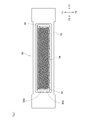
- FIG. 2 is a view showing a state in which the nozzle ejection surface 52 for ejecting paint is viewed from the front of the nozzle head unit 50.
- the nozzle ejection surface 52 is provided with a plurality of nozzle rows 55 in which the nozzles 54 are connected in a direction in which the nozzles 54 are inclined with respect to the width direction of the nozzle head unit 50.
- the nozzle row 55 includes a first nozzle row 55A existing on one side (Y2 side) in the main scanning direction (Y direction) and a second nozzle row existing on the other side in the main scanning direction. 55B (Y1 side) is provided.
- the droplets ejected from the nozzles 54 in the second nozzle row 55B are landed between the droplets ejected from the adjacent nozzles 54 in the first nozzle row 55A.
- the drive timing of the nozzle 54 is controlled. Thereby, the dot density can be improved at the time of painting.
- a single nozzle head 53 exists on the nozzle discharge surface 52.
- the nozzle discharge surface 52 may have a head group composed of a plurality of nozzle heads 53.
- a configuration in which a plurality of nozzle heads 53 are arranged in a staggered pattern while being aligned is mentioned, but the arrangement of the nozzle heads 53 in the head group does not have to be staggered. ..
- FIG. 4 is a diagram showing a schematic configuration for supplying paint to each nozzle 54.
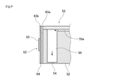
- FIG. 5 is a cross-sectional view showing a configuration in the vicinity of the row direction supply flow path 58, the nozzle pressurizing chamber 59, and the row direction discharge flow path 60.
- the nozzle head 53 includes a supply-side large flow path 57, a row-direction supply flow path 58, a nozzle pressurizing chamber 59, a row-direction discharge flow path 60, and a discharge-side large flow path. It is equipped with a road 61.
- the supply-side large flow path 57 is a flow path to which paint is supplied from the supply path 71 of the head-side circulation path described later.
- the row-direction supply flow path 58 is a flow path through which the paint in the supply-side large flow path 57 is diverted.
- the nozzle pressurizing chamber 59 is connected to the row direction supply flow path 58 via the nozzle supply flow path 59a. As a result, the paint is supplied to the nozzle pressurizing chamber 59 from the column direction supply flow path 58.
- the nozzle pressurizing chamber 59 is provided according to the number of nozzles 54, and the paint inside can be discharged from the nozzles 54 by using a drive element described later.
- the nozzle pressurizing chamber 59 is connected to the row direction discharge flow path 60 via a nozzle discharge flow path (not shown). Therefore, the paint that is not discharged from the nozzle 54 is discharged from the nozzle pressurizing chamber 59 to the row direction discharge flow path 60 via the nozzle discharge flow path 59b.
- the row direction discharge flow path 60 is connected to the discharge side large flow path 61.
- the discharge-side large flow path 61 is a flow path in which the paint discharged from each row-direction discharge flow path 60 merges.
- the discharge-side large flow path 61 is connected to the return path 72 of the head-side circulation path.
- the paint supplied from the supply path 71 of the head-side circulation path passes through the supply-side large flow path 57, the column direction supply flow path 58, the nozzle supply flow path 59a, and the nozzle pressurizing chamber 59, and the nozzle. It is discharged from 54. Further, the paint not discharged from the nozzle 54 passes from the nozzle pressurizing chamber 59 through the nozzle discharge flow path 59b, the row direction discharge flow path 60, and the discharge side large flow path 61 to the return path 72 of the head side circulation path. Will be returned.
- one row direction supply flow path 58 is arranged so as to correspond to one row direction discharge flow path 60.
- a plurality of (for example, two) row-direction discharge flow paths 60 may be arranged so as to correspond to one row-direction supply flow path 58.
- one row direction discharge flow path 60 may be arranged so as to correspond to the plurality of row direction supply flow paths 58.
- the piezoelectric substrate 62 is arranged on the top surface (the surface opposite to the nozzle 54) of the nozzle pressurizing chamber 59.
- the piezoelectric substrate 62 includes two piezoelectric ceramic layers 63a and 63b, which are piezoelectric bodies, and further includes a common electrode 64 and an individual electrode 65.
- the piezoelectric ceramic layers 63a and 63b are members that can be expanded and contracted by applying a voltage from the outside.
- piezoelectric ceramic layers 63a and 63b ceramic materials such as lead zirconate titanate (PZT), NaNbO3, BaTIO3, (BiNa) NbO3, and BiNaNb5O15, which have ferroelectricity, can be used. can.
- PZT lead zirconate titanate
- NaNbO3, BaTIO3, (BiNa) NbO3, and BiNaNb5O15 which have ferroelectricity
- the common electrode 64 is arranged between the piezoelectric ceramic layer 63a and the piezoelectric ceramic layer 63b. Further, a surface electrode (not shown) for a common electrode is formed on the upper surface of the piezoelectric substrate 62. The common electrode 64 and the surface electrode for the common electrode are electrically connected to each other through a through conductor (not shown) existing in the piezoelectric ceramic layer 63a. Further, the individual electrodes 65 are arranged at portions facing the nozzle pressurizing chamber 59. Further, in the piezoelectric ceramic layer 63a, the portion sandwiched between the common electrode 64 and the individual electrode 65 is polarized in the thickness direction.
- the piezoelectric ceramic layer 63a is distorted due to the piezoelectric effect. Therefore, when a predetermined drive signal is applied to the individual electrodes 65, the piezoelectric ceramic layer 63b relatively fluctuates so as to reduce the volume of the nozzle pressurizing chamber 59, whereby the paint is discharged.
- the common electrode 64 is arranged on the top surface of the nozzle pressurizing chamber 59, but the configuration is not limited to this.
- the common electrode 64 may adopt a configuration arranged on the side surface of the nozzle pressurizing chamber 59, and if the paint can be satisfactorily ejected from the nozzle 54, what is the case? May be adopted.
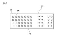
- FIG. 7 is a plan view showing the configuration of the nozzle discharge surface 52 of another nozzle head unit.
- a plurality of nozzles 54 may be arranged along the lateral direction (width direction; Y direction) of the nozzle head 53 to form the nozzle row 55.
- a plurality of nozzles 54 are arranged side by side in the lateral direction (width direction; main scanning direction) of the nozzle head 53 to form a nozzle row 55, but one (single) nozzle.
- Only 54 may be arranged in the lateral direction (width direction; main scanning direction) of the nozzle head 53. That is, the nozzle row 55 may be composed of one nozzle 54.
- the longitudinal direction of the nozzle head 53 is set with respect to the main scanning direction of the nozzle head 53. It may be tilted by an angle ⁇ . In the case of tilting in this way, it is possible to realize the same coating as the nozzle head 53 shown in FIG. 2 only by adjusting the ejection timing of the paint from each nozzle 54.
- FIG. 8 is a cross-sectional view showing the configuration of the nozzle head unit 50.
- FIG. 9 is a block diagram showing an electrical configuration in the vicinity of the nozzle head unit 50. As shown in FIGS. 8 and 9, the nozzle head unit 50 has an explosion-proof housing 70.
- the explosion-proof housing 70 has an internal space P1 sealed from the external atmosphere, and the internal pressure of the internal space P1 is increased by supplying an inert gas from the gas supply joint 81 (internal pressure of the internal space P1). Is higher than the pressure of the external atmosphere), and adopts an internal pressure explosion-proof structure. Further, in the explosion-proof housing 70, the internal space P1 is sealed so as not to cause ignition to the external atmosphere through all the joints and openings that isolate the internal space P1. Further, by maintaining the pressure of the non-flammable inert gas in the internal space P1 higher than the pressure of the external atmosphere, the flammable pressurizing gas in the external atmosphere can be prevented from entering the internal space P1. I'm preventing it. The explosion-proof performance of the explosion-proof housing 70 is ensured even by such a configuration for increasing the internal pressure.
- the explosion-proof housing 70 has a tubular portion 71 that covers the above-mentioned internal space P1, a bulging portion 72, and a front cover 73.
- the tubular portion 71 is a portion provided in a cylindrical shape (for example, a rectangular tubular shape) in which portions having the same width (cross-sectional area) are continuous.
- the width (cross-sectional area) of the tubular portion 71 may be partially different.
- the tubular portion 71 includes various shapes such as a rectangular housing and a cylindrical housing.
- the bulging portion 72 is a portion having a portion having a width (cross-sectional area) bulging more than the tubular portion 71, and the nozzle head 53 is arranged in the bulging portion 72 by utilizing such a bulge. ing.
- the front cover 73 is attached to the opening side of the bulging portion 72. That is, the front cover 73 is attached to the opening portion of the explosion-proof housing 70 away from the wrist portion 27.
- the nozzle head 53 is attached via the front cover 73. That is, the front cover 73 is provided with a mounting opening (not shown), and the nozzle head 53 is mounted on the front cover 73 with the nozzle discharge surface 52 of the nozzle head 53 exposed from the mounting opening. Has been done.
- the explosion-proof housing 70 is provided with a gas introduction port 74, and a gas supply joint 81 is attached to the gas introduction port 74.
- the gas introduction port 74 is provided on the bulging outer peripheral wall 72a of the bulging portion 72 described above.
- the bulging outer peripheral wall 72a is a wall surface facing the nozzle head 53 in FIG.
- the bulging outer peripheral wall 72a is a wall surface that does not face parallel to the top surface of the nozzle head 53 but faces at a predetermined angle, but faces parallel to the top surface of the nozzle head 53. It may be formed as follows.
- the gas supply joint 81 corresponds to the gas supply means, at least one of the pressurizing pipe line 83 and the pressurizing means 84 other than the gas supply joint 81 may also correspond to the gas supply means.
- the gas supply joint 81 can inject the inert gas toward the nozzle head 53.
- the inert gas is maintained at a temperature sufficiently lower than that of the heat sink 90 described later.
- a pressurizing pipe line 83 as shown in FIG. 9 is connected to the gas supply joint 81, and a pressurizing means 84 such as a compressor is connected to the pressurizing pipe line 83.
- the gas introduction port 74 is arranged in the vicinity of the nozzle head 53 in FIG. 8, and can supply the inert gas toward the nozzle head 53.
- the explosion-proof housing 70 is provided with a gas discharge port 75.
- a gas control valve 82 such as a proportional control valve is attached to the gas discharge port 75. Further, the gas control valve 82 corresponds to the gas discharge means. The gas control valve 82 makes it possible to adjust the flow rate at which the inert gas is discharged to adjust the pressure in the internal space P1.
- the gas control valve 82 is attached to the wall surface of the explosion-proof housing 70 on the side opposite to the gas supply joint 81 with the nozzle head 53 interposed therebetween in the internal space P1 of the explosion-proof housing 70.
- FIG. 8 shows a case where the gas control valve 82 is mounted closer to the ceiling surface 76 away from the nozzle discharge surface 52 than the center of the internal space P1.
- the mounting position of the gas control valve 82 is not limited to this, and any position is provided on the wall surface of the explosion-proof housing 70 on the opposite side of the nozzle head 53 from the gas supply joint 81. It may be.
- the gas control valve 82 may be attached to the wall surface of the explosion-proof housing 70 on the same side as the gas supply joint 81 with respect to the nozzle head 53. ..
- a heat sink 90 is attached to the nozzle head 53.
- the heat radiating plate 90 is attached to the side surface 53a of the nozzle head 53, which is a surface intersecting the nozzle discharge surface 52. As a result, the heat generated from the nozzle head 53 can be dissipated over a relatively large area.
- the heat radiating plate 90 corresponds to the heat radiating means.
- each side surface 53a it is preferable to attach a heat sink 90 to each side surface 53a, but if one heat sink 90 can provide sufficient heat dissipation performance, the two side surfaces 53a It may be attached to only one of the surfaces. Further, the heat sink 90 may be attached to the top surface 53b on the side opposite to the nozzle discharge surface 52.
- the heat radiating plate 90 is made of an aluminum-based metal which is superior in thermal conductivity and workability to iron or the like, but copper, which is superior in thermal conductivity to aluminum-based metal, may be used as a material. Further, in order to increase the surface area of the heat radiating plate 90, a configuration having a large number of fins may be used.
- a temperature sensor 100 is attached to the heat sink 90, and the temperature of the heat sink 90 is measured by the temperature sensor 100.
- the temperature sensor 100 include a PTC (Positive Temperature Coefficient) thermistor, an NTC (Negative Temperature Coefficient) thermistor, a thermocouple, an RTD (Resistance Temperature Detector), and a semiconductor temperature sensor.
- the temperature sensor 100 corresponds to the temperature measuring means.
- the temperature sensor 100 is connected to the circuit breaker 110 outside the explosion-proof housing 70 via a signal line (not shown).
- the circuit breaker 110 cuts off the supply of electric power to the nozzle head 53, and is a power line before and after the power supply circuit 120 that supplies electric power for driving to the drive driver 170 described later (nozzle head in FIG. 9). It is attached to the main control unit 130 side away from 53).
- the power supply circuit 120 corresponds to the power supply means.
- the circuit breaker 110 corresponds to the power cutoff means.
- the circuit breaker 110 When the temperature sensor 100 detects that the temperature of the nozzle head 53 (heat sink 90) is equal to or higher than the specified temperature, the circuit breaker 110 operates and the power supply to the nozzle head 53 is forcibly stopped. Be made to. This prevents the nozzle head 53 from rising above the specified temperature.
- the painting robot 10 is provided with a main control unit 130, and the main control unit 130 cooperates with each part of the painting robot 10 to perform painting on an object to be painted.
- a predetermined control signal is transmitted to the head control unit 140, the valve control unit 150, and the pressurizing means control unit 160.
- the main control unit 130 and the valve control unit 150 constitute control means, but at least one of the main control unit 130, the valve control unit 150, and the pressurizing means control unit 160 may constitute the control means.
- the circuit breaker 110 described above is arranged between the main control unit 130 and the power supply circuit 120. Therefore, when the circuit breaker 110 is activated, the power supply to the power supply circuit 120 is forcibly stopped, so that power is not supplied to the drive driver 170 for driving the nozzle head 53. Therefore, the drive of the piezoelectric substrate 62 is stopped.
- a control means different from the configuration shown in FIG. 9 may be configured.
- the circuit breaker 110 described above is arranged between the main control unit 130 and the head control unit 140, between the power supply circuit 120 and the drive driver 170, and between the head control unit 140 and the drive driver 170. The configuration may be adopted.
- the main control unit 130, the head control unit 140, the valve control unit 150, and the pressurizing means control unit 160 are composed of a CPU, a memory (ROM, RAM, non-volatile memory, etc.), and other elements.
- the memory stores programs and data for executing desired control.
- the head control unit 140 transmits a control signal related to the image to the drive driver 170 based on the command from the main control unit 130.
- the valve control unit 150 is a unit that controls the operation of the gas control valve 82 based on a command from the main control unit 130.
- the pressurizing means control unit 160 is a portion that controls the operation of the pressurizing means 84 based on a command from the main control unit 130.
- the drive driver 170 is a part that controls the application of electric power for driving the piezoelectric substrate 62 in the nozzle head 53 based on a command from the head control unit 140.
- the heat sink 90 is attached to the nozzle head 53. Therefore, the heat generated by the nozzle head 53 is released from the heat sink 90 to the internal space P1. Inert gas is supplied to the internal space P1 from the gas supply joint 81. Moreover, the gas supply joint 81 is attached to the bulging outer peripheral wall 72a, and the inert gas is injected toward the heat radiating plate 90. Therefore, the heat sink 90 is in a state where it is easily cooled by the inert gas.
- the inert gas in the internal space P1 is discharged from the gas control valve 82 attached to the gas discharge port 75.
- the valve control unit 150 controls the gas control valve 82 to adjust the flow rate of the inert gas discharged from the internal space P1.
- the pressure of the internal space P1 is adjusted to be higher than the pressure of the external atmosphere, for example.
- a temperature sensor 100 is attached to the heat sink 90, and the temperature of the heat sink 90 is measured by the temperature sensor 100. Then, when the temperature measured by the temperature sensor 100 reaches a temperature (specified temperature) that is not suitable for driving the nozzle head 53, a detection signal indicating that the specified temperature has been reached is transmitted to the circuit breaker 110. Then, the circuit breaker 110 immediately cuts off the power supply to the power supply circuit 120. As a result, the drive of the nozzle head 53 is forcibly stopped.
- the above specified temperature is higher than the temperature of the external atmosphere, but the temperature can be set in various ways. As an example, there are 125 degrees, 120 degrees, 100 degrees, and 80 degrees. Further, the specified temperature may be set to a temperature other than these temperatures.
- the inkjet coating robot 10 having the above configuration includes a plurality of nozzles 54, and supplies power to drive the nozzle head 53 for ejecting paint from the nozzles 54 by driving the piezoelectric substrate 62 and the piezoelectric substrate 62. It is provided with a power supply means (power supply circuit 120) to be mounted, and a robot arm R1 capable of mounting the nozzle head 53 on the tip portion and moving the mounted nozzle head 53.
- a power supply means power supply circuit 120
- the nozzle head 53 is covered with a portion other than the nozzle discharge surface 52 in a state where the nozzle discharge surface 52 is exposed to the outside, and the external atmosphere is prevented by preventing damage even if an explosion occurs in the internal space P1. It is provided in an explosion-proof housing 70 having an explosion-proof structure for preventing ignition of the nozzle. Further, in the explosion-proof housing 70, a heat radiating means (heat radiating plate 90) that dissipates heat generated from the nozzle head 53 is attached to the nozzle head 53, and in the explosion-proof housing 70, the temperature of the heat radiating means (heat radiating plate 90). A temperature measuring means (temperature sensor 100) for measuring the temperature is attached to the heat radiating means (heat radiating plate 90).
- a power cutoff means (circuit breaker 110) that cuts off the supply of power from the power supply means (power supply circuit 120) to the piezoelectric substrate 62, and the temperature measuring means (temperature sensor 100) reaches a specified temperature.
- the power cutoff means (circuit breaker 110) cuts off the power supply to the power supply means (power supply circuit 120) based on the detection signal from the temperature measuring means (temperature sensor 100).
- the temperature measuring means temperature sensor 100
- the heat radiating means heat radiating plate 90
- the temperature measuring means temperature sensor 100
- the power cutoff means cuts off the power supply to the power supply means (power supply circuit 120). Therefore, it is possible to suppress the temperature rise of the nozzle head 53 to a specified temperature or less (constant temperature or less). Therefore, in the nozzle head 53, it is possible to prevent an abnormal temperature rise.
- the nozzle head 53 is equipped with a heat radiating means (heat radiating plate 90), it is possible to suppress the temperature rise in the internal space P1.
- the nozzle head 53 is arranged in the internal space P1 of the explosion-proof housing 70, it is possible to isolate the portion where the temperature rises remarkably from the external atmosphere. Therefore, even if an explosion occurs in the internal space P1 or a spark or the like occurs in an electrically driven portion such as the piezoelectric substrate 62, it is possible to prevent the influence from being generated in the external atmosphere.
- the explosion-proof housing 70 has an internal pressure explosion-proof structure in which the internal pressure of the internal space P1 is higher than the pressure of the external atmosphere. With such a configuration, it is possible to satisfactorily prevent the external atmosphere from flowing into the internal space P1. Thereby, the explosion-proof performance of the explosion-proof housing 70 can be improved.
- the heat radiating means is a heat radiating plate 90, and the heat radiating plate 90 is attached to the side surface 53a of the nozzle head 53 that intersects the nozzle discharge surface 52.
- the explosion-proof housing 70 includes a gas supply means (gas supply joint 81) attached to the gas introduction port 74 formed in the explosion-proof housing 70 and a gas discharge port 75 formed in the explosion-proof housing 70. It is equipped with a gas discharge means (gas control valve 82) attached to the housing. Then, the inert gas is introduced from the gas introduction port 74, and the inert gas is discharged from the gas discharge means (gas control valve 82).
- the inert gas is supplied from the gas supply means (gas supply joint 81) to the internal space P1 of the explosion-proof housing 70, and the inert gas is used as the gas discharge means (gas control valve 82). ) Is discharged. Therefore, the inert gas can be circulated inside the internal space P1 and the heat radiated from the heat radiating means (heat radiating plate 90) can be satisfactorily discharged to the outside. As a result, the cooling performance of the nozzle head 53 can be further improved.
- the explosion-proof housing 70 is provided with a tubular portion 71 and a bulging portion 72 having a larger width direction than the outer peripheral surface of the tubular portion 71.
- the gas supply means (gas supply joint 81) is attached to the bulging outer peripheral wall 72a facing the heat radiating means (heat radiating plate 90) in the bulging portion 72, so that the gas supply means (gas supply joint 81) is directed toward the radiating means (heat radiating plate 90).
- the gas supply means (gas supply joint 81) injects the inert gas.
- the tubular portion 71 has a narrower width and a smaller cross-sectional area than the bulging portion 72, so that the weight of the explosion-proof material (metal, resin, etc.) used for the tubular portion 71 can be reduced. Can be reduced. Therefore, the behavior of the robot arm R1 can be improved. Further, since the gas introduction port 74 can be formed on the bulging outer peripheral wall 72a of the bulging portion 72 due to the presence of the bulging portion 72, the heat radiating means (heat radiating plate 90) is formed from the gas supply means (gas supply joint 81). A fresh inert gas (whose temperature is relatively lower than the interior space P1) can be injected toward. Thereby, the cooling performance of the nozzle head 53 can be improved.
- the gas supply means gas supply joint 81
- the gas discharge means is a gas control valve 82 capable of adjusting the flow rate of the inert gas, and the gas control valve 82 sandwiches the nozzle head 53 in the internal space P1 of the explosion-proof housing 70. It is attached to the wall surface of the explosion-proof housing 70 on the opposite side of the gas supply joint 81.
- the inert gas introduced from the gas supply means can be circulated in the internal space P1. Therefore, it is possible to prevent the fresh (temperature relatively lower than the internal space P1) inert gas from being immediately discharged to the outside. Therefore, the inert gas can be effectively utilized for lowering the temperature of the nozzle head 53, and the nozzle head 53 can be cooled more satisfactorily.
- the operation of the gas control valve 82 is controlled, and the flow rate of the inert gas discharged from the gas control valve 82 is controlled so that the internal pressure of the internal space P1 becomes higher than the pressure of the external atmosphere. It has a control means (valve control unit 150).
- the internal pressure of the internal space P1 can be made higher than that of the external atmosphere, so that it is possible to better prevent the external atmosphere from flowing into the internal space P1.
- the explosion-proof performance of the explosion-proof housing 70 can be further improved by enhancing the inside of the internal space P1.
- the heat sink 90 is described as the heat dissipation means.
- the heat dissipation means is not limited to the heat sink 90.
- the heat radiating means may be a cooling fan for forcibly flowing an inert gas, a water cooling mechanism for cooling the nozzle head 53 with cold water, a Pertier element, or the like, instead of the heat radiating plate 90 or together with the heat radiating plate 90. Is also good.
- the internal pressure of the internal space P1 is made higher than that of the external atmosphere by adjusting the flow rate of the inert gas discharged from the gas control valve 82.
- the internal pressure of the internal space P1 may be controlled to be higher than the external atmosphere.
- the temperature sensor 100 is attached to the heat radiating plate 90 corresponding to the heat radiating means.
- the temperature sensor 100 may be attached to a nozzle head 53 other than the heat sink 90 and a member fixed to the nozzle head 53.
- the explosion-proof housing 70 adopts an internal pressure explosion-proof structure as the explosion-proof structure.
- the explosion-proof structure in the explosion-proof housing 70 may be an explosion-proof structure other than the internal pressure explosion-proof structure.
- the explosion-proof housing 70 may adopt a pressure-resistant explosion-proof structure made of a pressure-resistant material, may adopt a safety-enhanced explosion-proof structure, or may adopt another explosion-proof structure.
- Nozzle pressurizing chamber 59a ... Nozzle supply flow path, 59b ... Nozzle discharge flow path, 60 ... Column direction discharge flow path, 61 ... Discharge side large flow path, 62 ... Hydraulic substrate, 63a ... Common electrode, 65 ... Individual electrode, 70 ... Explosion-proof housing, 71 ... Supply path, 71 ... Cylindrical part, 72 ... Return path, 72 ... Swelling part, 72a ... Swelling outer wall, 73 ... Front cover, 74 ... Gas Introductory port, 75 ... Gas discharge port, 76 ... Ceiling surface, 81 ... Gas supply joint (corresponding to gas supply means), 82 ... Gas control valve (corresponding to gas discharge means), 83 ...
Abstract
Provided is an inkjet-type vehicle painting machine capable of keeping temperature elevation of a nozzle head to a certain temperature or less. The painting robot 10 comprises a power supply means 120 for supplying power to drive a piezoelectric substrate 62 of a nozzle head 53, and a robot arm R1 for moving the nozzle head 53. The nozzle head 53 is provided in an explosion-proof housing 70 equipped with an explosion-proof construction. A heat dissipation means 90 that dissipates heat generated from the nozzle head 53 within the explosion-proof housing 70 is attached to the nozzle head 53. A temperature measurement means 100 for measuring the temperature of the heat dissipation means 90 is attached to the heat dissipation means 90. Also, there is provided a power cutoff means 110 for cutting off the supply of power from the power supply means 120 to the piezoelectric substrate 62 on the basis of a detection signal from the temperature measurement means 100 when the temperature measurement means 100 measures that a stipulated temperature has been reached.
Description
本発明は、塗装ロボットに関する。
The present invention relates to a painting robot.
自動車等の車両の塗装ラインにおいては、ロボットを用いたロボット塗装が主流となっている。このロボット塗装では、多関節ロボットの先端に回転霧化型の塗装ヘッドを取り付けた塗装機(回転霧化型の塗装機)が用いられているが、たとえば特許文献1に開示のように、インクジェット方式の塗装機を用いて、車両を塗装することが提案されている。また、たとえば特許文献2には、長尺形状のスプレーパターンにて塗装することが開示されている。
In the painting line of vehicles such as automobiles, robot painting using robots is the mainstream. In this robot painting, a painting machine (rotary atomization type painting machine) in which a rotary atomization type painting head is attached to the tip of an articulated robot is used. For example, as disclosed in Patent Document 1, inkjet. It has been proposed to paint the vehicle using a method of painting machine. Further, for example, Patent Document 2 discloses painting with a long spray pattern.
ところで、インクジェット式のノズルヘッドを駆動させる場合、その駆動部分(圧電基板)付近において、発熱が生じる。このような発熱によって温度上昇が生じると、電気的な特性が圧電基板等を含めた電気的な導通部分の特性が変化して、誤作動や破損等を起こしてしまう虞がある。
By the way, when driving an inkjet nozzle head, heat is generated near the driving portion (piezoelectric substrate). When the temperature rises due to such heat generation, the electrical characteristics of the electrically conductive portion including the piezoelectric substrate may change, resulting in malfunction or damage.
また、ノズルヘッドのノズルから吐出する塗料は、熱によって粘度等の特性が変化してしまい、車両の塗装品質が悪化してしまう虞がある。さらに、塗料の中には有機溶剤を含むものもあるが、そのような有機溶剤を含む塗料を吐出させる状態で、ノズルヘッドの著しい温度上昇が生じるのは好ましくない。
In addition, the paint discharged from the nozzle of the nozzle head may change its characteristics such as viscosity due to heat, and the paint quality of the vehicle may deteriorate. Further, although some paints contain an organic solvent, it is not preferable that the temperature of the nozzle head rises significantly in a state where the paint containing such an organic solvent is discharged.
本発明は上記の事情にもとづきなされたもので、ノズルヘッドの温度上昇を一定温度以下に抑えることが可能な塗装ロボットを提供しよう、とするものである。
The present invention has been made based on the above circumstances, and an object of the present invention is to provide a painting robot capable of suppressing a temperature rise of a nozzle head to a certain temperature or less.
上記課題を解決するために、本発明の第1の観点によると、塗装対象物に対し、ノズルから塗料を吐出することで塗装を行うための塗装ロボットであって、複数のノズルを備えると共に、圧電基板の駆動によってノズルから塗料を吐出させるノズルヘッドと、圧電基板を駆動させる電力を供給する電力供給手段と、ノズルヘッドを先端部に装着可能であると共に、装着されたノズルヘッドを移動させるロボットアームと、を備え、ノズルヘッドは、そのノズル吐出面が外部に露出する状態で、当該ノズル吐出面以外の部分を覆われる防爆ハウジング内に設けられていて、防爆ハウジング内では、ノズルヘッドから発生する熱を放熱する放熱手段がノズルヘッドに取り付けられていて、防爆ハウジング内では、放熱手段の温度を測定する温度測定手段が当該放熱手段に取り付けられていて、温度測定手段が規定温度に到達したことを測定した場合に、温度測定手段からの検出信号に基づいて、電力供給手段から圧電基板に向かう電力の供給を遮断する電力遮断手段を有している、ことを特徴とする塗装ロボットが提供される。
In order to solve the above problems, according to the first aspect of the present invention, it is a painting robot for painting an object to be painted by ejecting paint from a nozzle, and is provided with a plurality of nozzles and is provided with a plurality of nozzles. A nozzle head that ejects paint from a nozzle by driving a piezoelectric substrate, a power supply means that supplies power to drive the piezoelectric substrate, and a robot that can attach the nozzle head to the tip and move the attached nozzle head. The nozzle head is provided with an arm and is provided in an explosion-proof housing that covers a portion other than the nozzle discharge surface in a state where the nozzle discharge surface is exposed to the outside, and is generated from the nozzle head in the explosion-proof housing. A heat radiating means for radiating heat is attached to the nozzle head, and in the explosion-proof housing, a temperature measuring means for measuring the temperature of the radiating means is attached to the radiating means, and the temperature measuring means has reached a specified temperature. Provided by a painting robot characterized by having a power cutoff means for cutting off the supply of power from the power supply means to the piezoelectric substrate based on a detection signal from the temperature measuring means when the fact is measured. Will be done.
また、上述の発明において、防爆ハウジングは、その内部空間の内圧が外部雰囲気の圧力より高い内圧防爆構造を備える、ことが好ましい。
Further, in the above-mentioned invention, it is preferable that the explosion-proof housing has an internal pressure explosion-proof structure in which the internal pressure of the internal space is higher than the pressure of the external atmosphere.
また、上述の発明において、防爆ハウジングは、耐圧材で構成された耐圧防爆構造を備える、ことが好ましい。
Further, in the above-mentioned invention, it is preferable that the explosion-proof housing has a pressure-resistant explosion-proof structure made of a pressure-resistant material.
また、上述の発明において、放熱手段は、放熱板であり、放熱板は、ノズルヘッドのうちノズル吐出面に対して交差する側面に取り付けられている、ことが好ましい。
Further, in the above-mentioned invention, it is preferable that the heat radiating means is a heat radiating plate, and the radiating plate is attached to the side surface of the nozzle head that intersects the nozzle ejection surface.
また、上述の発明において、防爆ハウジングは、防爆ハウジングに形成された空気導入口に取り付けられる気体供給手段と、防爆ハウジングに形成された気体排出口に取り付けられた気体排出手段とを備えていて、気体供給手段からは不活性ガスが導入され、気体排出手段からは不活性ガスが排出される、ことが好ましい。
Further, in the above-described invention, the explosion-proof housing includes a gas supply means attached to an air inlet formed in the explosion-proof housing and a gas discharge means attached to the gas discharge port formed in the explosion-proof housing. It is preferable that the inert gas is introduced from the gas supply means and the inert gas is discharged from the gas discharge means.
また、上述の発明において、防爆ハウジングには、筒状部と、その筒状部の外周面よりも幅方向の寸法が大きく膨らんでいる膨出部が設けられていて、気体供給手段は、膨出部のうち放熱手段と向き合う膨出外周壁に取り付けられていることで、放熱手段に向けて気体供給手段が不活性ガスを噴射する、ことが好ましい。
Further, in the above-described invention, the explosion-proof housing is provided with a cylindrical portion and a bulging portion whose width direction is larger than the outer peripheral surface of the tubular portion, and the gas supply means is expanded. It is preferable that the gas supply means injects the inert gas toward the heat dissipation means because it is attached to the bulging outer peripheral wall of the protrusion facing the heat dissipation means.
また、上述の発明において、気体排出手段は、不活性ガスの流量を調整可能なガス制御弁であり、ガス制御弁は、防爆ハウジングの内部空間においてノズルヘッドを挟んでガス供給手段とは反対側の防爆ハウジングの壁面に取り付けられている、ことが好ましい。
Further, in the above-described invention, the gas discharge means is a gas control valve capable of adjusting the flow rate of the inert gas, and the gas control valve is on the opposite side of the gas supply means with the nozzle head sandwiched in the internal space of the explosion-proof housing. It is preferably mounted on the wall of the explosion-proof housing.
また、上述の発明において、ガス制御弁の作動を制御し、内部空間の内圧が外部雰囲気の圧力よりも高くなるようにガス制御弁から排出される不活性ガスの流量を制御する制御手段を有する、ことが好ましい。
Further, in the above-mentioned invention, there is a control means for controlling the operation of the gas control valve and controlling the flow rate of the inert gas discharged from the gas control valve so that the internal pressure in the internal space becomes higher than the pressure in the external atmosphere. , Is preferred.
本発明によると、ノズルヘッドの温度上昇を一定温度以下に抑えることが可能な塗装ロボットを提供することができる。
According to the present invention, it is possible to provide a painting robot capable of suppressing the temperature rise of the nozzle head to a certain temperature or less.
以下、本発明の各実施の形態に係る塗装ロボットについて、図面に基づいて説明する。なお、以下の説明においては、必要に応じて、X方向はノズル吐出面52(ノズルヘッド53)の長手方向とし、X1側は図2における右側、X2側は図2における左側とする。また、Y方向はノズル吐出面52(ノズルヘッド53)の短手方向(幅方向)とし、Y1側は図2における紙面上側、Y2側は図2における紙面下側とする。
Hereinafter, the painting robot according to each embodiment of the present invention will be described with reference to the drawings. In the following description, if necessary, the X direction is the longitudinal direction of the nozzle discharge surface 52 (nozzle head 53), the X1 side is the right side in FIG. 2, and the X2 side is the left side in FIG. Further, the Y direction is the lateral direction (width direction) of the nozzle ejection surface 52 (nozzle head 53), the Y1 side is the upper side of the paper surface in FIG. 2, and the Y2 side is the lower side of the paper surface in FIG.
本実施の形態の塗装ロボットは、自動車製造の工場における塗装ラインに位置する車両または車両部品(以下、車両の一部となる車両部品も車両として説明する)といった塗装対象物に対して、「塗装」を行うものであり、塗膜を塗装対象物の表面に形成して、その表面の保護や美観を与えることを目的としている。したがって、所定時間毎に、塗装ラインに沿って移動してくる車両に対し、一定の時間内に所望の塗装品質にて、塗装を行う必要がある。
The painting robot of the present embodiment "paints" a vehicle or a vehicle part (hereinafter, a vehicle part that is a part of the vehicle is also described as a vehicle) located on a painting line in an automobile manufacturing factory. The purpose is to form a coating film on the surface of the object to be painted to protect the surface and give it an aesthetic appearance. Therefore, it is necessary to paint the vehicle moving along the painting line at predetermined time intervals with a desired painting quality within a certain time.
また、本実施の形態の塗装ロボットでは、上述した塗膜を形成するのみならず、各種のデザインや画像を、車両や車両部品といった塗装対象物に対して形成することが可能である。
Further, in the painting robot of the present embodiment, it is possible not only to form the above-mentioned coating film but also to form various designs and images on the object to be painted such as a vehicle or a vehicle part.
(1-1.インクジェット式の車両用塗装機の全体構成について)
図1は、本発明の第1の実施の形態に係る塗装ロボット10の全体構成を示す概略図である。図1に示すように、塗装ロボット10は、ロボット本体20と、ノズルヘッドユニット50とを主要な構成要素としている。 (1-1. Overall configuration of inkjet type vehicle coating machine)
FIG. 1 is a schematic view showing the overall configuration of thepainting robot 10 according to the first embodiment of the present invention. As shown in FIG. 1, the painting robot 10 has a robot main body 20 and a nozzle head unit 50 as main components.
図1は、本発明の第1の実施の形態に係る塗装ロボット10の全体構成を示す概略図である。図1に示すように、塗装ロボット10は、ロボット本体20と、ノズルヘッドユニット50とを主要な構成要素としている。 (1-1. Overall configuration of inkjet type vehicle coating machine)
FIG. 1 is a schematic view showing the overall configuration of the
(1-2.塗装装置本体について)
図1に示すように、ロボット本体20は、基台21と、脚部22と、回転軸部23と、回転アーム24と、第1回動アーム25と、第2回動アーム26と、リスト部27と、これらを駆動させるための不図示のモータと、を主要な構成要素としている。なお、回転軸部23からリスト部27までの部分は、ロボットアームR1に対応するが、脚部22等のようなそれ以外の部分も、ロボットアームR1に対応するものとしても良い。 (1-2. About the main body of the painting device)
As shown in FIG. 1, the robotmain body 20 includes a base 21, legs 22, a rotating shaft 23, a rotating arm 24, a first rotating arm 25, a second rotating arm 26, and a list. The main components are a unit 27 and a motor (not shown) for driving them. The portion from the rotation shaft portion 23 to the wrist portion 27 corresponds to the robot arm R1, but other parts such as the leg portion 22 and the like may also correspond to the robot arm R1.
図1に示すように、ロボット本体20は、基台21と、脚部22と、回転軸部23と、回転アーム24と、第1回動アーム25と、第2回動アーム26と、リスト部27と、これらを駆動させるための不図示のモータと、を主要な構成要素としている。なお、回転軸部23からリスト部27までの部分は、ロボットアームR1に対応するが、脚部22等のようなそれ以外の部分も、ロボットアームR1に対応するものとしても良い。 (1-2. About the main body of the painting device)
As shown in FIG. 1, the robot
これらのうち、基台21は床面等の設置部位に設置される部分であるが、この基台21が設置部位に対して走行可能であっても良い。また、脚部22は、基台21から上部に向かい立設された部分である。なお、脚部22と基台21の間に関節部を設けて、脚部22が基台21に対して回動可能としても良い。
Of these, the base 21 is a part that is installed at the installation site such as the floor surface, but the base 21 may be able to travel with respect to the installation site. Further, the leg portion 22 is a portion erected from the base 21 toward the upper part. A joint portion may be provided between the leg portion 22 and the base 21 so that the leg portion 22 can rotate with respect to the base 21.
また、脚部22の上端には、回転軸部23が設けられている。この回転軸部23には、回転アーム24が回転自在な状態で取り付けられている。また、回転アーム24は、モータ(第1モータ)の駆動により回転させられるが、そのようなモータとしては、電気モータやエアモータを用いることが可能である。なお、塗装ロボット10が防爆エリアに設置されると共に電気モータを用いる場合には、回転軸部23のハウジング内の内圧を高める(内圧防爆構造の採用)等の防爆対策を講じることが好ましい(以下の各モータ(第2モータ~第6モータ)においても同様)。しかしながら、塗装ロボット10が防爆エリア以外の場所に設置される場合には、上記のような防爆対策を講じなくて良い。なお、ノズルヘッド53付近の防爆構造に関しては、後述する。
Further, a rotating shaft portion 23 is provided at the upper end of the leg portion 22. A rotary arm 24 is attached to the rotary shaft portion 23 in a rotatable state. Further, the rotary arm 24 is rotated by driving a motor (first motor), and as such a motor, an electric motor or an air motor can be used. When the painting robot 10 is installed in an explosion-proof area and an electric motor is used, it is preferable to take explosion-proof measures such as increasing the internal pressure inside the housing of the rotating shaft portion 23 (adopting an internal pressure explosion-proof structure) (hereinafter,). The same applies to each of the motors (second motor to sixth motor). However, when the painting robot 10 is installed in a place other than the explosion-proof area, it is not necessary to take the above-mentioned explosion-proof measures. The explosion-proof structure near the nozzle head 53 will be described later.
また、回転アーム24には、第1回動アーム25の一端側が回動可能な状態で取り付けられている。なお、第1回動アーム25を回転軸部23に対して相対的に回転させる第2モータ(図示省略)は、回転アーム24のハウジング内に収納されていても良く、第1回動アーム25のハウジング内に収納されていても良い。
Further, one end side of the first rotating arm 25 is attached to the rotating arm 24 in a rotatable state. The second motor (not shown) that rotates the first rotation arm 25 relative to the rotation shaft portion 23 may be housed in the housing of the rotation arm 24, and the first rotation arm 25 may be housed in the housing. It may be stored in the housing of.
また、第1回動アーム25の他端側には、第2回動アーム26の一端側が軸部を介して揺動自在な状態で取り付けられている。この第2回動アーム26を第1回動アーム25に対して相対的に回転させる第3モータ(図示省略)は、第1回動アーム25のハウジング内に収納されていても良く、第2回動アーム26のハウジング内に収納されていても良い。
Further, one end side of the second rotating arm 26 is attached to the other end side of the first rotating arm 25 in a swingable state via a shaft portion. The third motor (not shown) that rotates the second rotation arm 26 relative to the first rotation arm 25 may be housed in the housing of the first rotation arm 25, and is the second. It may be housed in the housing of the rotating arm 26.
この第2回動アーム26の他端側には、リスト部27が取り付けられている。リスト部27は、複数(たとえば3つ)の異なる向きの軸部を中心に、回転運動を可能としている。それにより、ノズルヘッドユニット50の向きを精度良くコントロールすることが可能となっている。なお、軸部の個数は、2つ以上であれば幾つでも良い。
A wrist portion 27 is attached to the other end side of the second rotating arm 26. The wrist portion 27 enables rotational movement around a plurality of (for example, three) shaft portions in different directions. As a result, it is possible to accurately control the orientation of the nozzle head unit 50. The number of shaft portions may be any number as long as it is two or more.
かかるリスト部27のそれぞれの軸部を中心とした回転運動を可能とするために、モータ(第4モータ~第6モータ;図示省略)が設けられている。なお、第4モータ~第6モータは、第2回動アーム26のハウジング内に収納されているが、その他の部位に収納されていても良い。
Motors (4th to 6th motors; not shown) are provided in order to enable rotational movement around each shaft portion of the wrist portion 27. Although the fourth motor to the sixth motor are housed in the housing of the second rotating arm 26, they may be housed in other parts.
また、リスト部27には、不図示のホルダ部を介してノズルヘッドユニット50が取り付けられている。すなわち、ノズルヘッドユニット50は、ホルダ部を介して、リスト部27に着脱自在に設けられている。
Further, the nozzle head unit 50 is attached to the wrist portion 27 via a holder portion (not shown). That is, the nozzle head unit 50 is detachably provided on the wrist portion 27 via the holder portion.
なお、上記のような、回転軸部23と、回転アーム24と、第1回動アーム25と、第2回動アーム26と、リスト部27と、これらを駆動させる第1モータ~第6モータと、を備える塗装ロボット10は、6軸で駆動可能なロボットである。しかしながら、塗装ロボット10は、4軸以上であれば、何軸で駆動するロボットであっても良い。
As described above, the rotary shaft portion 23, the rotary arm 24, the first rotary arm 25, the second rotary arm 26, the wrist portion 27, and the first motor to the sixth motor for driving them. The painting robot 10 including the above is a robot that can be driven by 6 axes. However, the painting robot 10 may be a robot driven by any number of axes as long as it has four or more axes.
(1-3.ノズルヘッドユニットについて)
次に、ノズルヘッドユニット50について説明する。リスト部27には、不図示のチャック部を介してノズルヘッドユニット50が取り付けられる。図2から図4に示すように、ノズルヘッドユニット50は、後述する防爆ハウジング70を備え、その防爆ハウジング70内に、種々の構成が内蔵されている。なお、防爆ハウジング70に内蔵される構成には、塗料を循環させる経路であるヘッド側循環経路(図示省略)や、ヘッド制御部140等が挙げられる。 (1-3. Nozzle head unit)
Next, thenozzle head unit 50 will be described. A nozzle head unit 50 is attached to the wrist portion 27 via a chuck portion (not shown). As shown in FIGS. 2 to 4, the nozzle head unit 50 includes an explosion-proof housing 70, which will be described later, and various configurations are built in the explosion-proof housing 70. Examples of the configuration built in the explosion-proof housing 70 include a head-side circulation path (not shown), which is a path for circulating paint, a head control unit 140, and the like.
次に、ノズルヘッドユニット50について説明する。リスト部27には、不図示のチャック部を介してノズルヘッドユニット50が取り付けられる。図2から図4に示すように、ノズルヘッドユニット50は、後述する防爆ハウジング70を備え、その防爆ハウジング70内に、種々の構成が内蔵されている。なお、防爆ハウジング70に内蔵される構成には、塗料を循環させる経路であるヘッド側循環経路(図示省略)や、ヘッド制御部140等が挙げられる。 (1-3. Nozzle head unit)
Next, the
図2は、ノズルヘッドユニット50のうち、塗料を吐出させるノズル吐出面52を正面視した状態を示す図である。図2に示すように、ノズル吐出面52には、ノズル54がノズルヘッドユニット50の幅方向に対して傾斜する方向に連なるノズル列55が複数設けられている。かかるノズル列55には、本実施の形態では、主走査方向(Y方向)の一方側(Y2側)に存在する第1ノズル列55Aと、主走査方向の他方側に存在する第2ノズル列55B(Y1側)とが設けられている。
FIG. 2 is a view showing a state in which the nozzle ejection surface 52 for ejecting paint is viewed from the front of the nozzle head unit 50. As shown in FIG. 2, the nozzle ejection surface 52 is provided with a plurality of nozzle rows 55 in which the nozzles 54 are connected in a direction in which the nozzles 54 are inclined with respect to the width direction of the nozzle head unit 50. In the present embodiment, the nozzle row 55 includes a first nozzle row 55A existing on one side (Y2 side) in the main scanning direction (Y direction) and a second nozzle row existing on the other side in the main scanning direction. 55B (Y1 side) is provided.
なお、塗料を吐出する場合、第1ノズル列55Aにおける隣り合うノズル54から吐出される液滴の間に、第2ノズル列55Bにおけるノズル54から吐出される液滴が着弾されるように、各ノズル54の駆動タイミングが制御される。それにより、塗装の際にドット密度を向上させることができる。
When ejecting the paint, the droplets ejected from the nozzles 54 in the second nozzle row 55B are landed between the droplets ejected from the adjacent nozzles 54 in the first nozzle row 55A. The drive timing of the nozzle 54 is controlled. Thereby, the dot density can be improved at the time of painting.
ところで、図2に示すように、ノズル吐出面52には、単一のノズルヘッド53が存在している。しかしながら、ノズル吐出面52には、複数のノズルヘッド53から構成されるヘッド群が存在するようにしても良い。この場合、一例として、図3に示すように、複数のノズルヘッド53を位置合わせしつつ千鳥状に配置する構成が挙げられるが、ヘッド群におけるノズルヘッド53の配置は千鳥状でなくても良い。
By the way, as shown in FIG. 2, a single nozzle head 53 exists on the nozzle discharge surface 52. However, the nozzle discharge surface 52 may have a head group composed of a plurality of nozzle heads 53. In this case, as an example, as shown in FIG. 3, a configuration in which a plurality of nozzle heads 53 are arranged in a staggered pattern while being aligned is mentioned, but the arrangement of the nozzle heads 53 in the head group does not have to be staggered. ..
図4は、各ノズル54へ塗料を供給する概略的な構成について示す図である。図5は、列方向供給流路58、ノズル加圧室59および列方向排出流路60付近の構成を示す断面図である。図4および図5に示すように、ノズルヘッド53は、供給側大流路57と、列方向供給流路58と、ノズル加圧室59と、列方向排出流路60と、排出側大流路61とを備えている。供給側大流路57は、後述するヘッド側循環経路の供給路71から塗料が供給される流路である。また、列方向供給流路58は、供給側大流路57内の塗料が、分流される流路である。
FIG. 4 is a diagram showing a schematic configuration for supplying paint to each nozzle 54. FIG. 5 is a cross-sectional view showing a configuration in the vicinity of the row direction supply flow path 58, the nozzle pressurizing chamber 59, and the row direction discharge flow path 60. As shown in FIGS. 4 and 5, the nozzle head 53 includes a supply-side large flow path 57, a row-direction supply flow path 58, a nozzle pressurizing chamber 59, a row-direction discharge flow path 60, and a discharge-side large flow path. It is equipped with a road 61. The supply-side large flow path 57 is a flow path to which paint is supplied from the supply path 71 of the head-side circulation path described later. Further, the row-direction supply flow path 58 is a flow path through which the paint in the supply-side large flow path 57 is diverted.
また、ノズル加圧室59は、列方向供給流路58とノズル供給流路59aを介して接続されている。それにより、ノズル加圧室59には、列方向供給流路58から塗料が供給される。このノズル加圧室59は、ノズル54の個数に対応して設けられていて、内部の塗料を後述する駆動素子を用いてノズル54から吐出させることができる。
Further, the nozzle pressurizing chamber 59 is connected to the row direction supply flow path 58 via the nozzle supply flow path 59a. As a result, the paint is supplied to the nozzle pressurizing chamber 59 from the column direction supply flow path 58. The nozzle pressurizing chamber 59 is provided according to the number of nozzles 54, and the paint inside can be discharged from the nozzles 54 by using a drive element described later.
また、ノズル加圧室59は、不図示のノズル排出流路を介して列方向排出流路60と接続されている。したがって、ノズル54から吐出されなかった塗料は、ノズル加圧室59内からノズル排出流路59bを介して、列方向排出流路60へと排出される。また、列方向排出流路60は、排出側大流路61と接続されている。排出側大流路61は、それぞれの列方向排出流路60から、排出された塗料が合流する流路である。この排出側大流路61は、ヘッド側循環経路の戻り経路72と接続されている。
Further, the nozzle pressurizing chamber 59 is connected to the row direction discharge flow path 60 via a nozzle discharge flow path (not shown). Therefore, the paint that is not discharged from the nozzle 54 is discharged from the nozzle pressurizing chamber 59 to the row direction discharge flow path 60 via the nozzle discharge flow path 59b. Further, the row direction discharge flow path 60 is connected to the discharge side large flow path 61. The discharge-side large flow path 61 is a flow path in which the paint discharged from each row-direction discharge flow path 60 merges. The discharge-side large flow path 61 is connected to the return path 72 of the head-side circulation path.
このような構成により、ヘッド側循環経路の供給路71から供給された塗料は、供給側大流路57、列方向供給流路58、ノズル供給流路59aおよびノズル加圧室59を経て、ノズル54から吐出される。また、ノズル54から吐出されなかった塗料は、ノズル加圧室59からノズル排出流路59b、列方向排出流路60および排出側大流路61を経て、ヘッド側循環経路の戻り経路72へと戻される。
With such a configuration, the paint supplied from the supply path 71 of the head-side circulation path passes through the supply-side large flow path 57, the column direction supply flow path 58, the nozzle supply flow path 59a, and the nozzle pressurizing chamber 59, and the nozzle. It is discharged from 54. Further, the paint not discharged from the nozzle 54 passes from the nozzle pressurizing chamber 59 through the nozzle discharge flow path 59b, the row direction discharge flow path 60, and the discharge side large flow path 61 to the return path 72 of the head side circulation path. Will be returned.
なお、図4に示す構成では、1本の列方向供給流路58には、1本の列方向排出流路60が対応するように配置されている。しかしながら、1本の列方向供給流路58に、複数本(たとえば2本)の列方向排出流路60が対応するように配置されていても良い。また、複数本の列方向供給流路58に、1本の列方向排出流路60が対応するように配置されていても良い。
In the configuration shown in FIG. 4, one row direction supply flow path 58 is arranged so as to correspond to one row direction discharge flow path 60. However, a plurality of (for example, two) row-direction discharge flow paths 60 may be arranged so as to correspond to one row-direction supply flow path 58. Further, one row direction discharge flow path 60 may be arranged so as to correspond to the plurality of row direction supply flow paths 58.
また、図5に示すように、ノズル加圧室59の天面(ノズル54とは反対側の面)には、圧電基板62が配置されている。この圧電基板62は、圧電体である2枚の圧電セラミック層63a,63bを備え、さらに共通電極64と、個別電極65とを備えている。圧電セラミック層63a,63bは、外部から電圧を印加することで、伸縮可能な部材である。このような圧電セラミック層63a,63bとしては、強誘電性を有する、チタン酸ジルコン酸鉛(PZT)系、NaNbO3系、BaTiO3系、(BiNa)NbO3系、BiNaNb5O15系等のセラミックス材料を用いることができる。
Further, as shown in FIG. 5, the piezoelectric substrate 62 is arranged on the top surface (the surface opposite to the nozzle 54) of the nozzle pressurizing chamber 59. The piezoelectric substrate 62 includes two piezoelectric ceramic layers 63a and 63b, which are piezoelectric bodies, and further includes a common electrode 64 and an individual electrode 65. The piezoelectric ceramic layers 63a and 63b are members that can be expanded and contracted by applying a voltage from the outside. As such piezoelectric ceramic layers 63a and 63b, ceramic materials such as lead zirconate titanate (PZT), NaNbO3, BaTIO3, (BiNa) NbO3, and BiNaNb5O15, which have ferroelectricity, can be used. can.
また、図5に示すように、共通電極64は、圧電セラミック層63aと圧電セラミック層63bの間に配置されている。また、圧電基板62の上面には、共通電極用の表面電極(不図示)が形成されている。これら共通電極64と共通電極用表面電極とは、圧電セラミック層63aに存在する不図示の貫通導体を通じて、電気的に接続されている。また、個別電極65は、上記のノズル加圧室59と対向する部位にそれぞれ配置されている。さらに、圧電セラミック層63aのうち、共通電極64と個別電極65とに挟まれた部分は、厚さ方向に分極している。したがって、個別電極65に電圧を印加すると、圧電効果によって圧電セラミック層63aが歪む。このため、所定の駆動信号を個別電極65に印加すると、ノズル加圧室59の体積を減少させるように圧電セラミック層63bが相対的に変動し、それによって塗料が吐出される。
Further, as shown in FIG. 5, the common electrode 64 is arranged between the piezoelectric ceramic layer 63a and the piezoelectric ceramic layer 63b. Further, a surface electrode (not shown) for a common electrode is formed on the upper surface of the piezoelectric substrate 62. The common electrode 64 and the surface electrode for the common electrode are electrically connected to each other through a through conductor (not shown) existing in the piezoelectric ceramic layer 63a. Further, the individual electrodes 65 are arranged at portions facing the nozzle pressurizing chamber 59. Further, in the piezoelectric ceramic layer 63a, the portion sandwiched between the common electrode 64 and the individual electrode 65 is polarized in the thickness direction. Therefore, when a voltage is applied to the individual electrodes 65, the piezoelectric ceramic layer 63a is distorted due to the piezoelectric effect. Therefore, when a predetermined drive signal is applied to the individual electrodes 65, the piezoelectric ceramic layer 63b relatively fluctuates so as to reduce the volume of the nozzle pressurizing chamber 59, whereby the paint is discharged.
なお、図5に示す構成では、共通電極64は、ノズル加圧室59の天面に配置されているが、このような構成には限られない。たとえば、図6に示すように、共通電極64は、ノズル加圧室59の側面に配置される構成を採用しても良く、その他、塗料をノズル54から良好に吐出可能であれば、どのような構成を採用しても良い。
In the configuration shown in FIG. 5, the common electrode 64 is arranged on the top surface of the nozzle pressurizing chamber 59, but the configuration is not limited to this. For example, as shown in FIG. 6, the common electrode 64 may adopt a configuration arranged on the side surface of the nozzle pressurizing chamber 59, and if the paint can be satisfactorily ejected from the nozzle 54, what is the case? May be adopted.
(1-4.ノズルヘッドユニットの他の構成について)
次に、ノズルヘッドユニットの他の構成について説明する。図7は、他のノズルヘッドユニットのノズル吐出面52の構成を示す平面図である。図7に示すように、複数のノズル54がノズルヘッド53の短手方向(幅方向;Y方向)に沿って並ぶことでノズル列55を構成するようにしても良い。なお、図7に示す構成では、複数のノズル54がノズルヘッド53の短手方向(幅方向;主走査方向)に並んでノズル列55を構成しているが、1つの(単一の)ノズル54のみがノズルヘッド53の短手方向(幅方向;主走査方向)に配置される構成としても良い。すなわち、ノズル列55が1つのノズル54から構成されていても良い。 (1-4. Other configurations of nozzle head unit)
Next, other configurations of the nozzle head unit will be described. FIG. 7 is a plan view showing the configuration of thenozzle discharge surface 52 of another nozzle head unit. As shown in FIG. 7, a plurality of nozzles 54 may be arranged along the lateral direction (width direction; Y direction) of the nozzle head 53 to form the nozzle row 55. In the configuration shown in FIG. 7, a plurality of nozzles 54 are arranged side by side in the lateral direction (width direction; main scanning direction) of the nozzle head 53 to form a nozzle row 55, but one (single) nozzle. Only 54 may be arranged in the lateral direction (width direction; main scanning direction) of the nozzle head 53. That is, the nozzle row 55 may be composed of one nozzle 54.
次に、ノズルヘッドユニットの他の構成について説明する。図7は、他のノズルヘッドユニットのノズル吐出面52の構成を示す平面図である。図7に示すように、複数のノズル54がノズルヘッド53の短手方向(幅方向;Y方向)に沿って並ぶことでノズル列55を構成するようにしても良い。なお、図7に示す構成では、複数のノズル54がノズルヘッド53の短手方向(幅方向;主走査方向)に並んでノズル列55を構成しているが、1つの(単一の)ノズル54のみがノズルヘッド53の短手方向(幅方向;主走査方向)に配置される構成としても良い。すなわち、ノズル列55が1つのノズル54から構成されていても良い。 (1-4. Other configurations of nozzle head unit)
Next, other configurations of the nozzle head unit will be described. FIG. 7 is a plan view showing the configuration of the
また、図7に示すようなノズルヘッド53を用いて車両200に塗装を行う場合、ノズルヘッド53の長手方向が、ノズルヘッド53の主走査方向に対して若干傾斜させた状態で塗装を実行するようにしても良い。たとえば、図2に示すノズルヘッド53の構成では、ノズル列55は主走査方向に対して角度αだけ傾斜しているとすると、ノズルヘッド53の長手方向を、ノズルヘッド53の主走査方向に対して角度αだけ傾斜させるようにしても良い。このように傾斜させる場合には、各ノズル54からの塗料の吐出タイミングを調整するだけで、図2に示すノズルヘッド53と同等の塗装を実現することができる。
Further, when painting the vehicle 200 using the nozzle head 53 as shown in FIG. 7, painting is performed in a state where the longitudinal direction of the nozzle head 53 is slightly inclined with respect to the main scanning direction of the nozzle head 53. You may do so. For example, in the configuration of the nozzle head 53 shown in FIG. 2, assuming that the nozzle row 55 is inclined by an angle α with respect to the main scanning direction, the longitudinal direction of the nozzle head 53 is set with respect to the main scanning direction of the nozzle head 53. It may be tilted by an angle α. In the case of tilting in this way, it is possible to realize the same coating as the nozzle head 53 shown in FIG. 2 only by adjusting the ejection timing of the paint from each nozzle 54.
(1-5.ノズルヘッドユニットの詳細な構成および温度センサについて)
次に、ノズルヘッドユニット50の詳細な構成および温度センサに関して説明する。図8は、ノズルヘッドユニット50の構成を示す断面図である。図9は、ノズルヘッドユニット50付近の電気的な構成を示すブロック図である。図8および図9に示すように、ノズルヘッドユニット50は、防爆ハウジング70を有している。 (1-5. Detailed configuration of nozzle head unit and temperature sensor)
Next, the detailed configuration of thenozzle head unit 50 and the temperature sensor will be described. FIG. 8 is a cross-sectional view showing the configuration of the nozzle head unit 50. FIG. 9 is a block diagram showing an electrical configuration in the vicinity of the nozzle head unit 50. As shown in FIGS. 8 and 9, the nozzle head unit 50 has an explosion-proof housing 70.
次に、ノズルヘッドユニット50の詳細な構成および温度センサに関して説明する。図8は、ノズルヘッドユニット50の構成を示す断面図である。図9は、ノズルヘッドユニット50付近の電気的な構成を示すブロック図である。図8および図9に示すように、ノズルヘッドユニット50は、防爆ハウジング70を有している。 (1-5. Detailed configuration of nozzle head unit and temperature sensor)
Next, the detailed configuration of the
防爆ハウジング70は、外部雰囲気から密閉された内部空間P1を有していて、その内部空間P1の内圧を、気体供給継手81からの不活性ガスの供給によって高めるようにした(内部空間P1の内圧が外部雰囲気の圧力より高い)、内圧防爆構造を採用している。また、防爆ハウジング70は、内部空間P1を隔離する全ての接合部や開口部分を通して、外部雰囲気へと引火を生じさせないように、内部空間P1が密閉されている。また、内部空間P1内の、引火性のない不活性ガスの圧力を、外部雰囲気の圧力よりも高く維持することで、外部雰囲気中の引火性の加圧用ガスが内部空間P1に侵入するのを防いでいる。このような内圧を高める構成によっても、防爆ハウジング70の防爆性能が確保されている。
The explosion-proof housing 70 has an internal space P1 sealed from the external atmosphere, and the internal pressure of the internal space P1 is increased by supplying an inert gas from the gas supply joint 81 (internal pressure of the internal space P1). Is higher than the pressure of the external atmosphere), and adopts an internal pressure explosion-proof structure. Further, in the explosion-proof housing 70, the internal space P1 is sealed so as not to cause ignition to the external atmosphere through all the joints and openings that isolate the internal space P1. Further, by maintaining the pressure of the non-flammable inert gas in the internal space P1 higher than the pressure of the external atmosphere, the flammable pressurizing gas in the external atmosphere can be prevented from entering the internal space P1. I'm preventing it. The explosion-proof performance of the explosion-proof housing 70 is ensured even by such a configuration for increasing the internal pressure.
ここで、防爆ハウジング70には、上記の内部空間P1を覆う筒状部71と、膨出部72と、フロントカバー73とが存在している。これらのうち、筒状部71は、その幅(断面積)が同じ部位が連続する筒状(たとえば矩形の筒状)に設けられている部位である。しかしながら、筒状部71の幅(断面積)は、その一部が異なっていても良い。なお、筒状部71には、矩形の筐体、円筒状の筐体等、種々の形状が含まれる。
Here, the explosion-proof housing 70 has a tubular portion 71 that covers the above-mentioned internal space P1, a bulging portion 72, and a front cover 73. Of these, the tubular portion 71 is a portion provided in a cylindrical shape (for example, a rectangular tubular shape) in which portions having the same width (cross-sectional area) are continuous. However, the width (cross-sectional area) of the tubular portion 71 may be partially different. The tubular portion 71 includes various shapes such as a rectangular housing and a cylindrical housing.
また、膨出部72は、筒状部71よりも幅(断面積)が膨らんだ部位を有する部分であり、そのような膨らみを利用して、膨出部72にはノズルヘッド53が配置されている。また、フロントカバー73は、膨出部72の開口側に取り付けられている。すなわち、フロントカバー73は、防爆ハウジング70のうち、リスト部27から離れた開口部位に取り付けられている。そして、このフロントカバー73を介してノズルヘッド53が取り付けられている。すなわち、フロントカバー73には図示を省略する取付用開口部が設けられていて、その取付用開口部からノズルヘッド53のノズル吐出面52が露出する状態で、ノズルヘッド53がフロントカバー73に取り付けられている。
Further, the bulging portion 72 is a portion having a portion having a width (cross-sectional area) bulging more than the tubular portion 71, and the nozzle head 53 is arranged in the bulging portion 72 by utilizing such a bulge. ing. Further, the front cover 73 is attached to the opening side of the bulging portion 72. That is, the front cover 73 is attached to the opening portion of the explosion-proof housing 70 away from the wrist portion 27. The nozzle head 53 is attached via the front cover 73. That is, the front cover 73 is provided with a mounting opening (not shown), and the nozzle head 53 is mounted on the front cover 73 with the nozzle discharge surface 52 of the nozzle head 53 exposed from the mounting opening. Has been done.
また、防爆ハウジング70には、気体導入口74が設けられていて、その気体導入口74には、気体供給継手81が取り付けられている。気体導入口74は、上述した膨出部72のうち膨出外周壁72aに設けられている。ここで、膨出外周壁72aは、図8においてノズルヘッド53と向き合う壁面である。ただし、膨出外周壁72aは、ノズルヘッド53の天面とは平行には向き合わずに、所定の角度をなして向き合っている壁面となっているが、ノズルヘッド53の天面と平行に向き合うように形成しても良い。なお、気体供給継手81は、気体供給手段に対応するが、この気体供給継手81以外の加圧用管路83および加圧手段84の少なくとも1つも、気体供給手段に対応するものとしても良い。
Further, the explosion-proof housing 70 is provided with a gas introduction port 74, and a gas supply joint 81 is attached to the gas introduction port 74. The gas introduction port 74 is provided on the bulging outer peripheral wall 72a of the bulging portion 72 described above. Here, the bulging outer peripheral wall 72a is a wall surface facing the nozzle head 53 in FIG. However, the bulging outer peripheral wall 72a is a wall surface that does not face parallel to the top surface of the nozzle head 53 but faces at a predetermined angle, but faces parallel to the top surface of the nozzle head 53. It may be formed as follows. Although the gas supply joint 81 corresponds to the gas supply means, at least one of the pressurizing pipe line 83 and the pressurizing means 84 other than the gas supply joint 81 may also correspond to the gas supply means.
このような膨出外周壁72aに気体導入口74が設けられていることで、気体供給継手81は、ノズルヘッド53に向かって不活性ガスを噴射することが可能となっている。なお、圧電基板62が作動している状態(発熱状態)では、不活性ガスは、後述する放熱板90よりも十分に低い温度に維持されている。
By providing the gas introduction port 74 on the bulging outer peripheral wall 72a, the gas supply joint 81 can inject the inert gas toward the nozzle head 53. In the state where the piezoelectric substrate 62 is operating (heat generation state), the inert gas is maintained at a temperature sufficiently lower than that of the heat sink 90 described later.
また、気体供給継手81には、図9に示すような加圧用管路83が接続されていて、その加圧用管路にはコンプレッサー等の加圧手段84が接続されている。なお、気体導入口74は、図8においては、ノズルヘッド53の近傍に配置されていて、ノズルヘッド53に向かうように、不活性ガスを供給することが可能となっている。
Further, a pressurizing pipe line 83 as shown in FIG. 9 is connected to the gas supply joint 81, and a pressurizing means 84 such as a compressor is connected to the pressurizing pipe line 83. The gas introduction port 74 is arranged in the vicinity of the nozzle head 53 in FIG. 8, and can supply the inert gas toward the nozzle head 53.
また、防爆ハウジング70には、気体排出口75が設けられている。この気体排出口75には、比例制御弁等のようなガス制御弁82が取り付けられている。また、ガス制御弁82は、気体排出手段に対応する。かかるガス制御弁82によって、不活性ガスを排出する流量を調整して、内部空間P1の圧力を調整することが可能となっている。
Further, the explosion-proof housing 70 is provided with a gas discharge port 75. A gas control valve 82 such as a proportional control valve is attached to the gas discharge port 75. Further, the gas control valve 82 corresponds to the gas discharge means. The gas control valve 82 makes it possible to adjust the flow rate at which the inert gas is discharged to adjust the pressure in the internal space P1.
ここで、ガス制御弁82は、防爆ハウジング70の内部空間P1において、ノズルヘッド53を挟んで気体供給継手81とは反対側の防爆ハウジング70の壁面に取り付けられている。このようなガス制御弁82の取付位置の一例として、図8には、内部空間P1の中心よりもノズル吐出面52から離れた天井面76に近接してガス制御弁82が取り付けられている場合が示されているが、ガス制御弁82の取付位置は、これには限られず、ノズルヘッド53を挟んで気体供給継手81とは反対側の防爆ハウジング70の壁面であれば、どのような位置であっても良い。また、ノズルヘッド53の冷却性能を十分に確保可能であれば、ノズルヘッド53に対し、気体供給継手81と同じ側の防爆ハウジング70の壁面に、ガス制御弁82が取り付けられるようにしても良い。
Here, the gas control valve 82 is attached to the wall surface of the explosion-proof housing 70 on the side opposite to the gas supply joint 81 with the nozzle head 53 interposed therebetween in the internal space P1 of the explosion-proof housing 70. As an example of such a mounting position of the gas control valve 82, FIG. 8 shows a case where the gas control valve 82 is mounted closer to the ceiling surface 76 away from the nozzle discharge surface 52 than the center of the internal space P1. However, the mounting position of the gas control valve 82 is not limited to this, and any position is provided on the wall surface of the explosion-proof housing 70 on the opposite side of the nozzle head 53 from the gas supply joint 81. It may be. Further, if the cooling performance of the nozzle head 53 can be sufficiently ensured, the gas control valve 82 may be attached to the wall surface of the explosion-proof housing 70 on the same side as the gas supply joint 81 with respect to the nozzle head 53. ..
図8および図9に示すように、ノズルヘッド53には、放熱板90が取り付けられている。放熱板90は、ノズルヘッド53のうち、ノズル吐出面52に対して交差する面である側面53aに取り付けられている。それにより、ノズルヘッド53から生じる熱を、比較的広い面積で放熱することが可能となっている。なお、放熱板90は、放熱手段に対応する。
As shown in FIGS. 8 and 9, a heat sink 90 is attached to the nozzle head 53. The heat radiating plate 90 is attached to the side surface 53a of the nozzle head 53, which is a surface intersecting the nozzle discharge surface 52. As a result, the heat generated from the nozzle head 53 can be dissipated over a relatively large area. The heat radiating plate 90 corresponds to the heat radiating means.
なお、側面53aは2面存在しているので、それぞれの側面53aに放熱板90を取り付けるのが好ましいが、1つの放熱板90で十分な放熱性能が得られる場合には、2面の側面53aのうちの1面のみに取り付けるようにしても良い。また、放熱板90は、ノズル吐出面52とは反対側の天面53bに取り付けるようにしても良い。
Since there are two side surfaces 53a, it is preferable to attach a heat sink 90 to each side surface 53a, but if one heat sink 90 can provide sufficient heat dissipation performance, the two side surfaces 53a It may be attached to only one of the surfaces. Further, the heat sink 90 may be attached to the top surface 53b on the side opposite to the nozzle discharge surface 52.
また、放熱板90は、鉄等よりも熱伝導率に優れると共に加工性にも優れるアルミニウム系金属を材質としているが、アルミニウム系金属よりも熱伝導率に優れる銅を材質としても良い。また、放熱板90の表面積を大きくするために、多数のフィンを有する構成としても良い。
Further, the heat radiating plate 90 is made of an aluminum-based metal which is superior in thermal conductivity and workability to iron or the like, but copper, which is superior in thermal conductivity to aluminum-based metal, may be used as a material. Further, in order to increase the surface area of the heat radiating plate 90, a configuration having a large number of fins may be used.
また、放熱板90には、温度センサ100が取り付けられていて、放熱板90の温度を温度センサ100で測定している。なお、温度センサ100としては、PTC(Positive Temperature Coefficient)サーミスタ、NTC(Negative Temperature Coefficient)サーミスタ、熱電対、RTD(Resistance Temperature Detector;温度抵抗体)、半導体温度センサ等が挙げられる。なお、温度センサ100は、温度測定手段に対応する。
Further, a temperature sensor 100 is attached to the heat sink 90, and the temperature of the heat sink 90 is measured by the temperature sensor 100. Examples of the temperature sensor 100 include a PTC (Positive Temperature Coefficient) thermistor, an NTC (Negative Temperature Coefficient) thermistor, a thermocouple, an RTD (Resistance Temperature Detector), and a semiconductor temperature sensor. The temperature sensor 100 corresponds to the temperature measuring means.
この温度センサ100は、図示を省略する信号線を介して、防爆ハウジング70の外部のサーキットブレーカ110に接続されている。このサーキットブレーカ110は、ノズルヘッド53への電力の供給を遮断するものであり、後述する駆動ドライバ170に駆動用の電力を供給する電力供給回路120の前後の電力線(図9においては、ノズルヘッド53から離れる主制御部130側)に取り付けられている。なお、電力供給回路120は、電力供給手段に対応する。なお、サーキットブレーカ110は、電力遮断手段に対応する。
The temperature sensor 100 is connected to the circuit breaker 110 outside the explosion-proof housing 70 via a signal line (not shown). The circuit breaker 110 cuts off the supply of electric power to the nozzle head 53, and is a power line before and after the power supply circuit 120 that supplies electric power for driving to the drive driver 170 described later (nozzle head in FIG. 9). It is attached to the main control unit 130 side away from 53). The power supply circuit 120 corresponds to the power supply means. The circuit breaker 110 corresponds to the power cutoff means.
上記の温度センサ100で、ノズルヘッド53(放熱板90)の温度が規定温度以上であることが検出されると、サーキットブレーカ110が作動して、ノズルヘッド53への電力供給は強制的に停止させられる。それにより、ノズルヘッド53が規定温度以上に温度上昇するのを防止している。
When the temperature sensor 100 detects that the temperature of the nozzle head 53 (heat sink 90) is equal to or higher than the specified temperature, the circuit breaker 110 operates and the power supply to the nozzle head 53 is forcibly stopped. Be made to. This prevents the nozzle head 53 from rising above the specified temperature.
なお、図9に示すように、塗装ロボット10には主制御部130が設けられていて、この主制御部130が塗装ロボット10の各部位が協働して塗装対象物に対して塗装が実行されるように、ヘッド制御部140、弁制御部150、および加圧手段制御部160に、所定の制御信号を送信する。なお、主制御部130と弁制御部150は、制御手段を構成するが、主制御部130、弁制御部150および加圧手段制御部160の少なくとも1つが制御手段を構成するものとしても良い。
As shown in FIG. 9, the painting robot 10 is provided with a main control unit 130, and the main control unit 130 cooperates with each part of the painting robot 10 to perform painting on an object to be painted. A predetermined control signal is transmitted to the head control unit 140, the valve control unit 150, and the pressurizing means control unit 160. The main control unit 130 and the valve control unit 150 constitute control means, but at least one of the main control unit 130, the valve control unit 150, and the pressurizing means control unit 160 may constitute the control means.
なお、図9に示す構成では、主制御部130と電力供給回路120の間には、上述したサーキットブレーカ110が配置されている。したがって、サーキットブレーカ110が作動した場合には、電力供給回路120への電力供給は強制的に停止させられるので、ノズルヘッド53を駆動するための駆動ドライバ170に電力が供給されない。したがって、圧電基板62の駆動は停止させられる。しかしながら、かかる図9に示す構成とは異なる制御手段を構成しても良い。たとえば、主制御部130とヘッド制御部140の間、電力供給回路120と駆動ドライバ170の間、およびヘッド制御部140と駆動ドライバ170の間の少なくとも一方に、上述したサーキットブレーカ110が配置される構成を採用しても良い。
In the configuration shown in FIG. 9, the circuit breaker 110 described above is arranged between the main control unit 130 and the power supply circuit 120. Therefore, when the circuit breaker 110 is activated, the power supply to the power supply circuit 120 is forcibly stopped, so that power is not supplied to the drive driver 170 for driving the nozzle head 53. Therefore, the drive of the piezoelectric substrate 62 is stopped. However, a control means different from the configuration shown in FIG. 9 may be configured. For example, the circuit breaker 110 described above is arranged between the main control unit 130 and the head control unit 140, between the power supply circuit 120 and the drive driver 170, and between the head control unit 140 and the drive driver 170. The configuration may be adopted.
なお、主制御部130、ヘッド制御部140、弁制御部150および加圧手段制御部160は、CPU、メモリ(ROM、RAM、不揮発メモリ等)、その他の要素から構成されている。また、メモリには、所望の制御を実行するためのプログラムおよびデータが記憶されている。
The main control unit 130, the head control unit 140, the valve control unit 150, and the pressurizing means control unit 160 are composed of a CPU, a memory (ROM, RAM, non-volatile memory, etc.), and other elements. In addition, the memory stores programs and data for executing desired control.
ここで、ヘッド制御部140は、主制御部130からの指令に基づいて、駆動ドライバ170へ画像に関する制御信号を送信する。また、弁制御部150は、主制御部130からの指令に基づいて、ガス制御弁82の作動を制御する部分である。また、加圧手段制御部160は、主制御部130からの指令に基づいて、加圧手段84の作動を制御する部分である。また、駆動ドライバ170は、ヘッド制御部140からの指令に基づいて、ノズルヘッド53内の圧電基板62を駆動させるための電力の印加を制御する部分である。
Here, the head control unit 140 transmits a control signal related to the image to the drive driver 170 based on the command from the main control unit 130. Further, the valve control unit 150 is a unit that controls the operation of the gas control valve 82 based on a command from the main control unit 130. Further, the pressurizing means control unit 160 is a portion that controls the operation of the pressurizing means 84 based on a command from the main control unit 130. Further, the drive driver 170 is a part that controls the application of electric power for driving the piezoelectric substrate 62 in the nozzle head 53 based on a command from the head control unit 140.
[2.作用について]
次に、上述のような構成を有する塗装ロボット10の作用について、以下に説明する。車両200への塗装を実行する場合、主制御部130での制御に基づいて、電力供給回路120から駆動ドライバ170へ電力が供給される。また、主制御部130からの指令に基づいて、ヘッド制御部140は、駆動ドライバ170へ塗装を行うための画像に関する制御信号を送信する。すると、圧電基板62が駆動されることで、ノズルヘッド53の温度は上昇する。 [2. About action]
Next, the operation of thepainting robot 10 having the above-described configuration will be described below. When painting the vehicle 200 is performed, electric power is supplied from the power supply circuit 120 to the drive driver 170 based on the control by the main control unit 130. Further, based on the command from the main control unit 130, the head control unit 140 transmits a control signal regarding an image for painting to the drive driver 170. Then, the temperature of the nozzle head 53 rises by driving the piezoelectric substrate 62.
次に、上述のような構成を有する塗装ロボット10の作用について、以下に説明する。車両200への塗装を実行する場合、主制御部130での制御に基づいて、電力供給回路120から駆動ドライバ170へ電力が供給される。また、主制御部130からの指令に基づいて、ヘッド制御部140は、駆動ドライバ170へ塗装を行うための画像に関する制御信号を送信する。すると、圧電基板62が駆動されることで、ノズルヘッド53の温度は上昇する。 [2. About action]
Next, the operation of the
ここで、ノズルヘッド53には放熱板90が取り付けられている。したがって、ノズルヘッド53で生じた熱は、放熱板90から内部空間P1へと放出される。なお、内部空間P1には、気体供給継手81から不活性ガスが供給されている。しかも気体供給継手81は、膨出外周壁72aに取り付けられていて、不活性ガスは、放熱板90に向けて噴射される。このため、放熱板90は、不活性ガスによって冷却され易い状態となっている。
Here, the heat sink 90 is attached to the nozzle head 53. Therefore, the heat generated by the nozzle head 53 is released from the heat sink 90 to the internal space P1. Inert gas is supplied to the internal space P1 from the gas supply joint 81. Moreover, the gas supply joint 81 is attached to the bulging outer peripheral wall 72a, and the inert gas is injected toward the heat radiating plate 90. Therefore, the heat sink 90 is in a state where it is easily cooled by the inert gas.
なお、内部空間P1の不活性ガスは、気体排出口75に取り付けられているガス制御弁82から排出される。ここで、ガス制御弁82を弁制御部150が制御することで、内部空間P1から排出される不活性ガスの流量が調整される。それにより、内部空間P1の圧力を、たとえば外部雰囲気の圧力よりも高くなるように調整される。
The inert gas in the internal space P1 is discharged from the gas control valve 82 attached to the gas discharge port 75. Here, the valve control unit 150 controls the gas control valve 82 to adjust the flow rate of the inert gas discharged from the internal space P1. Thereby, the pressure of the internal space P1 is adjusted to be higher than the pressure of the external atmosphere, for example.
ここで、放熱板90には温度センサ100が取り付けられていて、その温度センサ100によって放熱板90の温度が計測される。そして、温度センサ100で測定された温度が、ノズルヘッド53を駆動させるのにふさわしくない温度(規定温度)に到達すると、かかる規定温度に到達した旨の検出信号を、サーキットブレーカ110に送信する。すると、サーキットブレーカ110は、電力供給回路120への電力供給を即座に遮断する。それにより、ノズルヘッド53の駆動は強制的に停止させられる。
Here, a temperature sensor 100 is attached to the heat sink 90, and the temperature of the heat sink 90 is measured by the temperature sensor 100. Then, when the temperature measured by the temperature sensor 100 reaches a temperature (specified temperature) that is not suitable for driving the nozzle head 53, a detection signal indicating that the specified temperature has been reached is transmitted to the circuit breaker 110. Then, the circuit breaker 110 immediately cuts off the power supply to the power supply circuit 120. As a result, the drive of the nozzle head 53 is forcibly stopped.
なお、上記の規定温度は、外部雰囲気の温度よりも高い温度であるが、その温度は種々設定することが可能である。その一例としては、125度、120度、100度、80度とするものがある。また、規定温度は、これらの温度以外に設定されても良い。
The above specified temperature is higher than the temperature of the external atmosphere, but the temperature can be set in various ways. As an example, there are 125 degrees, 120 degrees, 100 degrees, and 80 degrees. Further, the specified temperature may be set to a temperature other than these temperatures.
[3.効果について]
以上のような構成のインクジェット方式の塗装ロボット10においては、複数のノズル54を備えると共に、圧電基板62の駆動によってノズル54から塗料を吐出させるノズルヘッド53と、圧電基板62を駆動させる電力を供給する電力供給手段(電力供給回路120)と、ノズルヘッド53を先端部に装着可能であると共に、装着されたノズルヘッド53を移動させるロボットアームR1と、を備えている。 [3. About the effect]
Theinkjet coating robot 10 having the above configuration includes a plurality of nozzles 54, and supplies power to drive the nozzle head 53 for ejecting paint from the nozzles 54 by driving the piezoelectric substrate 62 and the piezoelectric substrate 62. It is provided with a power supply means (power supply circuit 120) to be mounted, and a robot arm R1 capable of mounting the nozzle head 53 on the tip portion and moving the mounted nozzle head 53.
以上のような構成のインクジェット方式の塗装ロボット10においては、複数のノズル54を備えると共に、圧電基板62の駆動によってノズル54から塗料を吐出させるノズルヘッド53と、圧電基板62を駆動させる電力を供給する電力供給手段(電力供給回路120)と、ノズルヘッド53を先端部に装着可能であると共に、装着されたノズルヘッド53を移動させるロボットアームR1と、を備えている。 [3. About the effect]
The
そして、ノズルヘッド53は、そのノズル吐出面52が外部に露出する状態で、当該ノズル吐出面52以外の部分を覆われると共に、内部空間P1において爆発が生じても損傷を防止することで外部雰囲気への引火を防止するための防爆構造を備える防爆ハウジング70内に設けられている。また、防爆ハウジング70内では、ノズルヘッド53から発生する熱を放熱する放熱手段(放熱板90)がノズルヘッド53に取り付けられていて、防爆ハウジング70内では、放熱手段(放熱板90)の温度を測定する温度測定手段(温度センサ100)が放熱手段(放熱板90)に取り付けられている。また、電力供給手段(電力供給回路120)から圧電基板62に向かう電力の供給を遮断する電力遮断手段(サーキットブレーカ110)を有していて、温度測定手段(温度センサ100)が規定温度に到達したことを測定した場合に、温度測定手段(温度センサ100)からの検出信号に基づいて、電力遮断手段(サーキットブレーカ110)は電力供給手段(電力供給回路120)への電力供給を遮断する。
The nozzle head 53 is covered with a portion other than the nozzle discharge surface 52 in a state where the nozzle discharge surface 52 is exposed to the outside, and the external atmosphere is prevented by preventing damage even if an explosion occurs in the internal space P1. It is provided in an explosion-proof housing 70 having an explosion-proof structure for preventing ignition of the nozzle. Further, in the explosion-proof housing 70, a heat radiating means (heat radiating plate 90) that dissipates heat generated from the nozzle head 53 is attached to the nozzle head 53, and in the explosion-proof housing 70, the temperature of the heat radiating means (heat radiating plate 90). A temperature measuring means (temperature sensor 100) for measuring the temperature is attached to the heat radiating means (heat radiating plate 90). Further, it has a power cutoff means (circuit breaker 110) that cuts off the supply of power from the power supply means (power supply circuit 120) to the piezoelectric substrate 62, and the temperature measuring means (temperature sensor 100) reaches a specified temperature. When it is measured, the power cutoff means (circuit breaker 110) cuts off the power supply to the power supply means (power supply circuit 120) based on the detection signal from the temperature measuring means (temperature sensor 100).
このように構成する場合には、温度測定手段(温度センサ100)が放熱手段(放熱板90)に取り付けられていて、その温度測定手段(温度センサ100)が規定温度に到達したことを測定した場合に、電力遮断手段(サーキットブレーカ110)は電力供給手段(電力供給回路120)への電力供給を遮断される。このため、ノズルヘッド53の温度上昇を規定温度以下(一定温度以下)に抑えることが可能となる。したがって、ノズルヘッド53において、異常な温度上昇を防止することが可能となる。
In this case, it was measured that the temperature measuring means (temperature sensor 100) was attached to the heat radiating means (heat radiating plate 90) and the temperature measuring means (temperature sensor 100) reached the specified temperature. In this case, the power cutoff means (circuit breaker 110) cuts off the power supply to the power supply means (power supply circuit 120). Therefore, it is possible to suppress the temperature rise of the nozzle head 53 to a specified temperature or less (constant temperature or less). Therefore, in the nozzle head 53, it is possible to prevent an abnormal temperature rise.
このため、上記のような温度上昇により、誤って内部空間P1や外部雰囲気において爆発が生じるのを防止することが可能となる。また、ノズルヘッド53内の圧電基板62が温度上昇によって熱暴走するのを防止することが可能となる。また、上記のような温度上昇により、塗料の粘度が増加して塗装品質が低下するのを防止することが可能となる。
Therefore, it is possible to prevent an explosion from accidentally occurring in the internal space P1 or the external atmosphere due to the temperature rise as described above. Further, it is possible to prevent the piezoelectric substrate 62 in the nozzle head 53 from causing thermal runaway due to a temperature rise. Further, it is possible to prevent the viscosity of the coating material from increasing and the coating quality from deteriorating due to the temperature increase as described above.
また、ノズルヘッド53には放熱手段(放熱板90)が取り付けられているので、内部空間P1における温度上昇を抑えることが可能となる。
Further, since the nozzle head 53 is equipped with a heat radiating means (heat radiating plate 90), it is possible to suppress the temperature rise in the internal space P1.
また、ノズルヘッド53は、防爆ハウジング70の内部空間P1に配置されているので、温度上昇が顕著に生じる部位を、外部雰囲気から隔離することが可能となる。そのため、仮に内部空間P1において爆発が生じたり、圧電基板62のような電気的な駆動部位で火花等が生じても、その影響を外部雰囲気に生じさせるのを防ぐことができる。
Further, since the nozzle head 53 is arranged in the internal space P1 of the explosion-proof housing 70, it is possible to isolate the portion where the temperature rises remarkably from the external atmosphere. Therefore, even if an explosion occurs in the internal space P1 or a spark or the like occurs in an electrically driven portion such as the piezoelectric substrate 62, it is possible to prevent the influence from being generated in the external atmosphere.
また、上述の実施の形態では、防爆ハウジング70は、その内部空間P1の内圧が外部雰囲気の圧力より高い内圧防爆構造を備えている。このように構成することで、内部空間P1に外部雰囲気が流入するのを良好に防ぐことができる。それにより、防爆ハウジング70の防爆性能を良好なものとすることができる。
Further, in the above-described embodiment, the explosion-proof housing 70 has an internal pressure explosion-proof structure in which the internal pressure of the internal space P1 is higher than the pressure of the external atmosphere. With such a configuration, it is possible to satisfactorily prevent the external atmosphere from flowing into the internal space P1. Thereby, the explosion-proof performance of the explosion-proof housing 70 can be improved.
また、上述の実施の形態では、放熱手段は、放熱板90であり、放熱板90は、ノズルヘッド53のうちノズル吐出面52に対して交差する側面53aに取り付けられている。
Further, in the above-described embodiment, the heat radiating means is a heat radiating plate 90, and the heat radiating plate 90 is attached to the side surface 53a of the nozzle head 53 that intersects the nozzle discharge surface 52.
このように構成することで、比較的大面積の側面53aに、同じく大面積の放熱板90を取り付ける構成とすることができる。このため、ノズルヘッド53の冷却性能を向上させることが可能となる。
With this configuration, it is possible to attach the heat sink 90 having a large area to the side surface 53a having a relatively large area. Therefore, it is possible to improve the cooling performance of the nozzle head 53.
また、本実施の形態では、防爆ハウジング70には、防爆ハウジング70に形成された気体導入口74に取り付けられる気体供給手段(気体供給継手81)と、防爆ハウジング70に形成された気体排出口75に取り付けられた気体排出手段(ガス制御弁82)とを備えている。そして、気体導入口74からは不活性ガスが導入され、気体排出手段(ガス制御弁82)からは不活性ガスが排出される。
Further, in the present embodiment, the explosion-proof housing 70 includes a gas supply means (gas supply joint 81) attached to the gas introduction port 74 formed in the explosion-proof housing 70 and a gas discharge port 75 formed in the explosion-proof housing 70. It is equipped with a gas discharge means (gas control valve 82) attached to the housing. Then, the inert gas is introduced from the gas introduction port 74, and the inert gas is discharged from the gas discharge means (gas control valve 82).
このように構成することで、防爆ハウジング70の内部空間P1には、気体供給手段(気体供給継手81)から不活性ガスが供給されると共に、その不活性ガスは気体排出手段(ガス制御弁82)から排出される。このため、内部空間P1の内部で、不活性ガスを循環させることができ、放熱手段(放熱板90)からの放熱を良好に外部に排出させることができる。それにより、ノズルヘッド53の冷却性能を一層向上させることが可能となる。
With this configuration, the inert gas is supplied from the gas supply means (gas supply joint 81) to the internal space P1 of the explosion-proof housing 70, and the inert gas is used as the gas discharge means (gas control valve 82). ) Is discharged. Therefore, the inert gas can be circulated inside the internal space P1 and the heat radiated from the heat radiating means (heat radiating plate 90) can be satisfactorily discharged to the outside. As a result, the cooling performance of the nozzle head 53 can be further improved.
また、本実施の形態では、防爆ハウジング70には、筒状部71と、その筒状部71の外周面よりも幅方向の寸法が大きく膨らんでいる膨出部72が設けられている。また、気体供給手段(気体供給継手81)は、膨出部72のうち放熱手段(放熱板90)と向き合う膨出外周壁72aに取り付けられていることで、放熱手段(放熱板90)に向けて気体供給手段(気体供給継手81)が不活性ガスを噴射する。
Further, in the present embodiment, the explosion-proof housing 70 is provided with a tubular portion 71 and a bulging portion 72 having a larger width direction than the outer peripheral surface of the tubular portion 71. Further, the gas supply means (gas supply joint 81) is attached to the bulging outer peripheral wall 72a facing the heat radiating means (heat radiating plate 90) in the bulging portion 72, so that the gas supply means (gas supply joint 81) is directed toward the radiating means (heat radiating plate 90). The gas supply means (gas supply joint 81) injects the inert gas.
このように構成することで、筒状部71は、膨出部72よりも幅が狭く断面積が小さくなるので、筒状部71に用いられる防爆用の材料(金属、樹脂等)の重量を低減することができる。したがって、ロボットアームR1の挙動を向上させることができる。また、膨出部72の存在により、膨出部72の膨出外周壁72aに気体導入口74を形成することができるので、気体供給手段(気体供給継手81)から放熱手段(放熱板90)に向けて、新鮮な(温度が内部空間P1よりも相対的に低い)不活性ガスを噴射させることができる。それにより、ノズルヘッド53の冷却性能を向上させることができる。
With this configuration, the tubular portion 71 has a narrower width and a smaller cross-sectional area than the bulging portion 72, so that the weight of the explosion-proof material (metal, resin, etc.) used for the tubular portion 71 can be reduced. Can be reduced. Therefore, the behavior of the robot arm R1 can be improved. Further, since the gas introduction port 74 can be formed on the bulging outer peripheral wall 72a of the bulging portion 72 due to the presence of the bulging portion 72, the heat radiating means (heat radiating plate 90) is formed from the gas supply means (gas supply joint 81). A fresh inert gas (whose temperature is relatively lower than the interior space P1) can be injected toward. Thereby, the cooling performance of the nozzle head 53 can be improved.
また、本実施の形態では、気体排出手段は、不活性ガスの流量を調整可能なガス制御弁82であり、そのガス制御弁82は、防爆ハウジング70の内部空間P1において、ノズルヘッド53を挟んで気体供給継手81とは反対側の防爆ハウジング70の壁面に取り付けられている。
Further, in the present embodiment, the gas discharge means is a gas control valve 82 capable of adjusting the flow rate of the inert gas, and the gas control valve 82 sandwiches the nozzle head 53 in the internal space P1 of the explosion-proof housing 70. It is attached to the wall surface of the explosion-proof housing 70 on the opposite side of the gas supply joint 81.
このように構成することで、気体供給手段(気体供給継手81)から導入された不活性ガスを内部空間P1において循環させることができる。そのため、新鮮な(温度が内部空間P1よりも相対的に低い)不活性ガスが即座に外部に排出させることを防ぐことができる。したがって、不活性ガスをノズルヘッド53の温度低下に有効に活用することができ、ノズルヘッド53を一層良好に冷却させることができる。
With this configuration, the inert gas introduced from the gas supply means (gas supply joint 81) can be circulated in the internal space P1. Therefore, it is possible to prevent the fresh (temperature relatively lower than the internal space P1) inert gas from being immediately discharged to the outside. Therefore, the inert gas can be effectively utilized for lowering the temperature of the nozzle head 53, and the nozzle head 53 can be cooled more satisfactorily.
また、本実施の形態では、ガス制御弁82の作動を制御し、内部空間P1の内圧が外部雰囲気の圧力よりも高くなるようにガス制御弁82から排出される不活性ガスの流量を制御する制御手段(弁制御部150)を有する。
Further, in the present embodiment, the operation of the gas control valve 82 is controlled, and the flow rate of the inert gas discharged from the gas control valve 82 is controlled so that the internal pressure of the internal space P1 becomes higher than the pressure of the external atmosphere. It has a control means (valve control unit 150).
このように構成することで、内部空間P1の内圧を外部雰囲気よりも高くすることができるので、内部空間P1に外部雰囲気が流入するのを一層良好に防ぐことができる。それにより、内部空間P1の内部を高めることで、防爆ハウジング70の防爆性能を一層良好なものとすることができる。
With such a configuration, the internal pressure of the internal space P1 can be made higher than that of the external atmosphere, so that it is possible to better prevent the external atmosphere from flowing into the internal space P1. As a result, the explosion-proof performance of the explosion-proof housing 70 can be further improved by enhancing the inside of the internal space P1.
[4.変形例について]
以上、本発明の一実施の形態について説明したが、本発明は、上記の実施の形態以外に、種々変形可能である。以下に、その一例について説明する。 [4. About transformation example]
Although one embodiment of the present invention has been described above, the present invention can be variously modified in addition to the above-described embodiment. An example thereof will be described below.
上述した実施の形態では、放熱手段として放熱板90について説明している。しかしながら、放熱手段は放熱板90には限られない。たとえば、放熱手段は、放熱板90に代えて、または放熱板90と共に、不活性ガスを強制的に流動させる冷却ファン、冷水によってノズルヘッド53を冷却する水冷機構、ペルチエ素子等が該当するものとしても良い。
In the above-described embodiment, the heat sink 90 is described as the heat dissipation means. However, the heat dissipation means is not limited to the heat sink 90. For example, the heat radiating means may be a cooling fan for forcibly flowing an inert gas, a water cooling mechanism for cooling the nozzle head 53 with cold water, a Pertier element, or the like, instead of the heat radiating plate 90 or together with the heat radiating plate 90. Is also good.
また、上述の実施の形態では、ガス制御弁82から排出される不活性ガスの流量を調整することで、内部空間P1の内圧を外部雰囲気よりも高くしている。しかしながら、加圧手段84の作動を加圧手段制御部160によって制御することで、内部空間P1の内圧を、外部雰囲気よりも高くするように制御しても良い。
Further, in the above-described embodiment, the internal pressure of the internal space P1 is made higher than that of the external atmosphere by adjusting the flow rate of the inert gas discharged from the gas control valve 82. However, by controlling the operation of the pressurizing means 84 by the pressurizing means control unit 160, the internal pressure of the internal space P1 may be controlled to be higher than the external atmosphere.
また、上述の実施の形態では、放熱手段に対応する放熱板90に、温度センサ100が取り付けられている。しかしながら、温度センサ100は、放熱板90以外のノズルヘッド53およびそのノズルヘッド53に固定される部材に、取り付けるようにしても良い。
Further, in the above-described embodiment, the temperature sensor 100 is attached to the heat radiating plate 90 corresponding to the heat radiating means. However, the temperature sensor 100 may be attached to a nozzle head 53 other than the heat sink 90 and a member fixed to the nozzle head 53.
また、上述の実施の形態では、防爆ハウジング70は、防爆構造として内圧防爆構造を採用したものとなっている。しかしながら、防爆ハウジング70における防爆構造は、内圧防爆構造以外の防爆構造であっても良い。たとえば、防爆ハウジング70は、耐圧材で構成された耐圧防爆構造を採用しても良く、安全増防爆構造を採用しても良く、その他の防爆構造を採用しても良い。
Further, in the above-described embodiment, the explosion-proof housing 70 adopts an internal pressure explosion-proof structure as the explosion-proof structure. However, the explosion-proof structure in the explosion-proof housing 70 may be an explosion-proof structure other than the internal pressure explosion-proof structure. For example, the explosion-proof housing 70 may adopt a pressure-resistant explosion-proof structure made of a pressure-resistant material, may adopt a safety-enhanced explosion-proof structure, or may adopt another explosion-proof structure.
10…塗装ロボット、20…ロボット本体、21…基台、22…脚部、23…回転軸部、24…回転アーム、25…第1回動アーム、26…第2回動アーム、27…リスト部、30…チャック部、40…塗料供給部、50…ノズルヘッドユニット、51…ヘッドカバー、52…ノズル吐出面、52a…側面、53…ノズルヘッド、53a…側面、53b…天面、54…ノズル、54A…ノズル、54B…ノズル、55…ノズル列、55A…第1ノズル列、55B…第2ノズル列、57…供給側大流路、58…列方向供給流路、59…ノズル加圧室、59a…ノズル供給流路、59b…ノズル排出流路、60…列方向排出流路、61…排出側大流路、62…圧電基板、63a…圧電セラミック層、63b…圧電セラミック層、64…共通電極、65…個別電極、70…防爆ハウジング、71…供給路、71…筒状部、72…戻り経路、72…膨出部、72a…膨出外周壁、73…フロントカバー、74…気体導入口、75…気体排出口、76…天井面、81…気体供給継手(気体供給手段に対応)、82…ガス制御弁(気体排出手段に対応)、83…加圧用管路、84…加圧手段、90…放熱板(放熱手段に対応)、100…温度センサ(温度測定手段に対応)、110…サーキットブレーカ(電力遮断手段に対応)、120…電力供給回路(電力供給手段に対応)、130…主制御部、140…ヘッド制御部、150…弁制御部(制御手段に対応)、160…加圧手段制御部、170…駆動ドライバ、200…車両、P1…内部空間、R1…ロボットアーム
10 ... painting robot, 20 ... robot body, 21 ... base, 22 ... legs, 23 ... rotating shaft, 24 ... rotating arm, 25 ... first rotating arm, 26 ... second rotating arm, 27 ... list Part, 30 ... Chuck part, 40 ... Paint supply part, 50 ... Nozzle head unit, 51 ... Head cover, 52 ... Nozzle discharge surface, 52a ... Side surface, 53 ... Nozzle head, 53a ... Side surface, 53b ... Top surface, 54 ... Nozzle , 54A ... Nozzle, 54B ... Nozzle, 55 ... Nozzle row, 55A ... First nozzle row, 55B ... Second nozzle row, 57 ... Supply side large flow path, 58 ... Row direction supply flow path, 59 ... Nozzle pressurizing chamber , 59a ... Nozzle supply flow path, 59b ... Nozzle discharge flow path, 60 ... Column direction discharge flow path, 61 ... Discharge side large flow path, 62 ... Hydraulic substrate, 63a ... Common electrode, 65 ... Individual electrode, 70 ... Explosion-proof housing, 71 ... Supply path, 71 ... Cylindrical part, 72 ... Return path, 72 ... Swelling part, 72a ... Swelling outer wall, 73 ... Front cover, 74 ... Gas Introductory port, 75 ... Gas discharge port, 76 ... Ceiling surface, 81 ... Gas supply joint (corresponding to gas supply means), 82 ... Gas control valve (corresponding to gas discharge means), 83 ... Pressurizing pipeline, 84 ... Addition Pressure means, 90 ... Heat dissipation plate (corresponding to heat dissipation means), 100 ... Temperature sensor (corresponding to temperature measuring means), 110 ... Circuit breaker (corresponding to power cutoff means), 120 ... Power supply circuit (corresponding to power supply means) , 130 ... main control unit, 140 ... head control unit, 150 ... valve control unit (corresponding to control means), 160 ... pressurizing means control unit, 170 ... drive driver, 200 ... vehicle, P1 ... internal space, R1 ... robot arm
Claims (8)
- 塗装対象物に対し、ノズルから塗料を吐出することで塗装を行うための塗装ロボットであって、
複数の前記ノズルを備えると共に、圧電基板の駆動によって前記ノズルから前記塗料を吐出させるノズルヘッドと、
前記圧電基板を駆動させる電力を供給する電力供給手段と、
前記ノズルヘッドを先端部に装着可能であると共に、装着された前記ノズルヘッドを移動させるロボットアームと、
を備え、
前記ノズルヘッドは、そのノズル吐出面が外部に露出する状態で、当該ノズル吐出面以外の部分を覆われる防爆ハウジング内に設けられていて、
前記防爆ハウジング内では、前記ノズルヘッドから発生する熱を放熱する放熱手段が前記ノズルヘッドに取り付けられていて、
前記防爆ハウジング内では、前記放熱手段の温度を測定する温度測定手段が当該放熱手段に取り付けられていて、
前記温度測定手段が規定温度に到達したことを測定した場合に、前記温度測定手段からの検出信号に基づいて、前記電力供給手段から前記圧電基板に向かう電力の供給を遮断する電力遮断手段を有している、
ことを特徴とする塗装ロボット。 It is a painting robot that paints an object to be painted by ejecting paint from a nozzle.
A nozzle head provided with a plurality of the nozzles and ejecting the paint from the nozzles by driving a piezoelectric substrate.
A power supply means for supplying electric power for driving the piezoelectric substrate, and
A robot arm that can be attached to the tip of the nozzle head and that moves the attached nozzle head,
Equipped with
The nozzle head is provided in an explosion-proof housing that covers a portion other than the nozzle discharge surface in a state where the nozzle discharge surface is exposed to the outside.
In the explosion-proof housing, a heat radiating means for radiating heat generated from the nozzle head is attached to the nozzle head.
In the explosion-proof housing, a temperature measuring means for measuring the temperature of the heat radiating means is attached to the heat radiating means.
There is a power cutoff means for cutting off the supply of electric power from the power supply means to the piezoelectric substrate based on the detection signal from the temperature measuring means when the temperature measuring means measures that the temperature has reached a specified temperature. is doing,
A painting robot featuring that. - 請求項1記載の塗装ロボットであって、
前記防爆ハウジングは、その内部空間の内圧が外部雰囲気の圧力より高い内圧防爆構造を備える、
ことを特徴とする塗装ロボット。 The painting robot according to claim 1.
The explosion-proof housing has an internal pressure explosion-proof structure in which the internal pressure of the internal space is higher than the pressure of the external atmosphere.
A painting robot featuring that. - 請求項1記載の塗装ロボットであって、
前記防爆ハウジングは、耐圧材で構成された耐圧防爆構造を備える、
ことを特徴とする塗装ロボット。 The painting robot according to claim 1.
The explosion-proof housing has a pressure-resistant explosion-proof structure made of a pressure-resistant material.
A painting robot featuring that. - 請求項1から3のいずれか1項に記載の塗装ロボットであって、
前記放熱手段は、放熱板であり、
前記放熱板は、前記ノズルヘッドのうち前記ノズル吐出面に対して交差する側面に取り付けられている、
ことを特徴とする塗装ロボット。 The painting robot according to any one of claims 1 to 3.
The heat radiating means is a heat radiating plate.
The heat sink is attached to a side surface of the nozzle head that intersects the nozzle discharge surface.
A painting robot featuring that. - 請求項1から4のいずれか1項に記載の塗装ロボットであって、
前記防爆ハウジングは、前記防爆ハウジングに形成された空気導入口に取り付けられる気体供給手段と、前記防爆ハウジングに形成された気体排出口に取り付けられた気体排出手段とを備えていて、
前記気体供給手段からは不活性ガスが導入され、前記気体排出手段からは前記不活性ガスが排出される、
ことを特徴とする塗装ロボット。 The painting robot according to any one of claims 1 to 4.
The explosion-proof housing includes a gas supply means attached to an air inlet formed in the explosion-proof housing and a gas discharge means attached to a gas discharge port formed in the explosion-proof housing.
The inert gas is introduced from the gas supply means, and the inert gas is discharged from the gas discharge means.
A painting robot featuring that. - 請求項5記載の塗装ロボットであって、
前記防爆ハウジングには、筒状部と、その筒状部の外周面よりも幅方向の寸法が大きく膨らんでいる膨出部が設けられていて、
前記気体供給手段は、前記膨出部のうち前記放熱手段と向き合う膨出外周壁に取り付けられていることで、前記放熱手段に向けて前記気体供給手段が前記不活性ガスを噴射する、
ことを特徴とする塗装ロボット。 The painting robot according to claim 5.
The explosion-proof housing is provided with a cylindrical portion and a bulging portion whose width direction is larger than the outer peripheral surface of the tubular portion.
The gas supply means is attached to the bulging outer peripheral wall of the bulging portion facing the heat radiating means, so that the gas supplying means injects the inert gas toward the radiating means.
A painting robot featuring that. - 請求項6記載の塗装ロボットであって、
前記気体排出手段は、前記不活性ガスの流量を調整可能なガス制御弁であり、
前記ガス制御弁は、前記防爆ハウジングの前記内部空間において前記ノズルヘッドを挟んで前記気体供給手段とは反対側の前記防爆ハウジングの壁面に取り付けられている、
ことを特徴とする塗装ロボット。 The painting robot according to claim 6.
The gas discharging means is a gas control valve capable of adjusting the flow rate of the inert gas.
The gas control valve is attached to the wall surface of the explosion-proof housing on the side opposite to the gas supply means with the nozzle head sandwiched in the internal space of the explosion-proof housing.
A painting robot featuring that. - 請求項7記載の塗装ロボットであって、
前記ガス制御弁の作動を制御し、前記内部空間の内圧が外部雰囲気の圧力よりも高くなるように前記ガス制御弁から排出される前記不活性ガスの流量を制御する制御手段を有する
ことを特徴とする塗装ロボット。 The painting robot according to claim 7.
It is characterized by having a control means for controlling the operation of the gas control valve and controlling the flow rate of the inert gas discharged from the gas control valve so that the internal pressure in the internal space becomes higher than the pressure in the external atmosphere. Painting robot.
Priority Applications (5)
| Application Number | Priority Date | Filing Date | Title |
|---|---|---|---|
| CN202080065069.6A CN114401795B (en) | 2020-06-29 | 2020-06-29 | Coating robot |
| PCT/JP2020/025473 WO2022003759A1 (en) | 2020-06-29 | 2020-06-29 | Painting robot |
| US17/753,811 US11701678B1 (en) | 2020-06-29 | 2020-06-29 | Painting robot |
| JP2022533263A JP7231790B2 (en) | 2020-06-29 | 2020-06-29 | painting robot |
| EP20942912.5A EP4173723A4 (en) | 2020-06-29 | 2020-06-29 | Painting robot |
Applications Claiming Priority (1)
| Application Number | Priority Date | Filing Date | Title |
|---|---|---|---|
| PCT/JP2020/025473 WO2022003759A1 (en) | 2020-06-29 | 2020-06-29 | Painting robot |
Publications (1)
| Publication Number | Publication Date |
|---|---|
| WO2022003759A1 true WO2022003759A1 (en) | 2022-01-06 |
Family
ID=79315752
Family Applications (1)
| Application Number | Title | Priority Date | Filing Date |
|---|---|---|---|
| PCT/JP2020/025473 WO2022003759A1 (en) | 2020-06-29 | 2020-06-29 | Painting robot |
Country Status (5)
| Country | Link |
|---|---|
| US (1) | US11701678B1 (en) |
| EP (1) | EP4173723A4 (en) |
| JP (1) | JP7231790B2 (en) |
| CN (1) | CN114401795B (en) |
| WO (1) | WO2022003759A1 (en) |
Citations (8)
| Publication number | Priority date | Publication date | Assignee | Title |
|---|---|---|---|---|
| JPS6078658A (en) * | 1983-10-07 | 1985-05-04 | Mitsubishi Heavy Ind Ltd | Electromotive type painting robot |
| JPH0672652U (en) * | 1993-03-26 | 1994-10-11 | トリニティ工業株式会社 | Robot coating equipment |
| JPH0890471A (en) * | 1994-09-19 | 1996-04-09 | Suzuki Motor Corp | Industrial robot |
| JPH10230200A (en) * | 1997-02-20 | 1998-09-02 | Tokico Ltd | Coating robot |
| JP2008514504A (en) * | 2004-09-30 | 2008-05-08 | アーベーベー アーエス | Door opening and closing mechanism used for industrial robots |
| JP2015036127A (en) * | 2013-08-12 | 2015-02-23 | トヨタ自動車九州株式会社 | Painting apparatus |
| JP2017035693A (en) | 2008-10-24 | 2017-02-16 | デュール システムズ アーゲーDurr Systems AG | Coating equipment and coating method |
| JP2018502702A (en) | 2014-12-01 | 2018-02-01 | デュール システムズ アーゲーDurr Systems AG | Coating method and corresponding coating equipment |
Family Cites Families (12)
| Publication number | Priority date | Publication date | Assignee | Title |
|---|---|---|---|---|
| US20030155434A1 (en) * | 2002-02-01 | 2003-08-21 | Rini Daniel P. | Spray nozzle apparatus and method of use |
| JP2011016319A (en) * | 2009-07-10 | 2011-01-27 | Fujifilm Corp | Piezoelectric device, driving method of piezoelectric element, and liquid ejector |
| JP5967350B2 (en) * | 2012-01-24 | 2016-08-10 | セイコーエプソン株式会社 | Liquid ejecting head module and liquid ejecting apparatus |
| KR101461738B1 (en) | 2012-12-21 | 2014-11-14 | 주식회사 포스코 | Apparatus for heating materials and coatting system having the same |
| JP6270896B2 (en) * | 2016-03-29 | 2018-01-31 | 本田技研工業株式会社 | COATING NOZZLE, COATING DEVICE, AND COATING METHOD USING THEM |
| JP6806144B2 (en) * | 2016-04-18 | 2021-01-06 | コニカミノルタ株式会社 | Inkjet head, head module and inkjet recorder |
| DE102016014943A1 (en) * | 2016-12-14 | 2018-06-14 | Dürr Systems Ag | Printhead with tempering device |
| JP2019010695A (en) * | 2017-06-29 | 2019-01-24 | 株式会社安川電機 | robot |
| CN107471638A (en) * | 2017-07-18 | 2017-12-15 | 葛顺英 | A kind of energy-saving 3D printing equipment |
| DE102017122492A1 (en) * | 2017-09-27 | 2019-03-28 | Dürr Systems Ag | Applicator with an integrated control circuit |
| JP2019206051A (en) * | 2018-05-29 | 2019-12-05 | 川崎重工業株式会社 | Scavenging device and robot system comprising same, and scavenging method |
| JP2022514559A (en) * | 2018-12-19 | 2022-02-14 | スリーエム イノベイティブ プロパティズ カンパニー | Automatic coating system with smart end effector tool |
-
2020
- 2020-06-29 CN CN202080065069.6A patent/CN114401795B/en active Active
- 2020-06-29 JP JP2022533263A patent/JP7231790B2/en active Active
- 2020-06-29 US US17/753,811 patent/US11701678B1/en active Active
- 2020-06-29 WO PCT/JP2020/025473 patent/WO2022003759A1/en unknown
- 2020-06-29 EP EP20942912.5A patent/EP4173723A4/en active Pending
Patent Citations (8)
| Publication number | Priority date | Publication date | Assignee | Title |
|---|---|---|---|---|
| JPS6078658A (en) * | 1983-10-07 | 1985-05-04 | Mitsubishi Heavy Ind Ltd | Electromotive type painting robot |
| JPH0672652U (en) * | 1993-03-26 | 1994-10-11 | トリニティ工業株式会社 | Robot coating equipment |
| JPH0890471A (en) * | 1994-09-19 | 1996-04-09 | Suzuki Motor Corp | Industrial robot |
| JPH10230200A (en) * | 1997-02-20 | 1998-09-02 | Tokico Ltd | Coating robot |
| JP2008514504A (en) * | 2004-09-30 | 2008-05-08 | アーベーベー アーエス | Door opening and closing mechanism used for industrial robots |
| JP2017035693A (en) | 2008-10-24 | 2017-02-16 | デュール システムズ アーゲーDurr Systems AG | Coating equipment and coating method |
| JP2015036127A (en) * | 2013-08-12 | 2015-02-23 | トヨタ自動車九州株式会社 | Painting apparatus |
| JP2018502702A (en) | 2014-12-01 | 2018-02-01 | デュール システムズ アーゲーDurr Systems AG | Coating method and corresponding coating equipment |
Non-Patent Citations (1)
| Title |
|---|
| See also references of EP4173723A4 |
Also Published As
| Publication number | Publication date |
|---|---|
| CN114401795B (en) | 2023-05-26 |
| EP4173723A4 (en) | 2024-03-27 |
| US11701678B1 (en) | 2023-07-18 |
| US20230211367A1 (en) | 2023-07-06 |
| EP4173723A1 (en) | 2023-05-03 |
| JP7231790B2 (en) | 2023-03-01 |
| JPWO2022003759A1 (en) | 2022-01-06 |
| CN114401795A (en) | 2022-04-26 |
Similar Documents
| Publication | Publication Date | Title |
|---|---|---|
| US6074043A (en) | Spray device for ink-jet printer having a multilayer membrane for ejecting ink | |
| US7997695B2 (en) | Liquid ejecting head, liquid ejecting apparatus, and actuator | |
| WO2021205537A1 (en) | Ink-jet type vehicle coating machine and vehicle coating method | |
| WO2022003759A1 (en) | Painting robot | |
| JP7285827B2 (en) | Coating machine and coating method | |
| CN114555239A (en) | Coating robot and coating method using same | |
| US20090058968A1 (en) | Inkjet print head and method of printing therewith | |
| US6848773B1 (en) | Piezoelectric ink jet printing module | |
| TW201603890A (en) | Liquid discharge device and liquid discharge method | |
| JP2009262421A (en) | Ink-jet head and ink-jet type recording apparatus | |
| JP2004509783A5 (en) | ||
| JP2018001524A (en) | Liquid discharge device | |
| JP2010082901A (en) | Liquid droplet jetting apparatus | |
| US10173422B2 (en) | Liquid ejecting head and liquid ejecting apparatus | |
| JP2003291348A (en) | Ink jet recording head and nonlinear electric element | |
| JP4752834B2 (en) | Weight measuring method, electro-optical device manufacturing method, and semiconductor device manufacturing method | |
| JP2006255994A (en) | Droplet discharging device, and droplet discharging method | |
| JP2831424B2 (en) | Ink jet recording device | |
| JP2006228496A (en) | Droplet discharge apparatus and method as well as manufacturing method of organic electroluminescent apparatus | |
| JP6020222B2 (en) | Inkjet head and inkjet printer equipped with the same | |
| JPH0358850A (en) | Liquid jet recorder | |
| US20200384773A1 (en) | Liquid ejection head | |
| JP3159272B2 (en) | Ink jet print head and ink jet printer | |
| JP2004230211A (en) | Solution jetting apparatus and method for jetting solution | |
| JPH0671883A (en) | Ink jet printing head and ink jet printer |
Legal Events
| Date | Code | Title | Description |
|---|---|---|---|
| 121 | Ep: the epo has been informed by wipo that ep was designated in this application |
Ref document number: 20942912 Country of ref document: EP Kind code of ref document: A1 |
|
| ENP | Entry into the national phase |
Ref document number: 2022533263 Country of ref document: JP Kind code of ref document: A |
|
| NENP | Non-entry into the national phase |
Ref country code: DE |
|
| ENP | Entry into the national phase |
Ref document number: 2020942912 Country of ref document: EP Effective date: 20230130 |