WO2021200773A1 - プラズマ生成装置 - Google Patents
プラズマ生成装置 Download PDFInfo
- Publication number
- WO2021200773A1 WO2021200773A1 PCT/JP2021/013168 JP2021013168W WO2021200773A1 WO 2021200773 A1 WO2021200773 A1 WO 2021200773A1 JP 2021013168 W JP2021013168 W JP 2021013168W WO 2021200773 A1 WO2021200773 A1 WO 2021200773A1
- Authority
- WO
- WIPO (PCT)
- Prior art keywords
- plasma
- chamber
- unit
- potential
- gas
- Prior art date
- Legal status (The legal status is an assumption and is not a legal conclusion. Google has not performed a legal analysis and makes no representation as to the accuracy of the status listed.)
- Ceased
Links
Images


Classifications
-
- H—ELECTRICITY
- H05—ELECTRIC TECHNIQUES NOT OTHERWISE PROVIDED FOR
- H05H—PLASMA TECHNIQUE; PRODUCTION OF ACCELERATED ELECTRICALLY-CHARGED PARTICLES OR OF NEUTRONS; PRODUCTION OR ACCELERATION OF NEUTRAL MOLECULAR OR ATOMIC BEAMS
- H05H1/00—Generating plasma; Handling plasma
- H05H1/24—Generating plasma
- H05H1/2406—Generating plasma using dielectric barrier discharges, i.e. with a dielectric interposed between the electrodes
- H05H1/2431—Generating plasma using dielectric barrier discharges, i.e. with a dielectric interposed between the electrodes using cylindrical electrodes, e.g. rotary drums
-
- H—ELECTRICITY
- H01—ELECTRIC ELEMENTS
- H01J—ELECTRIC DISCHARGE TUBES OR DISCHARGE LAMPS
- H01J49/00—Particle spectrometers or separator tubes
- H01J49/02—Details
- H01J49/10—Ion sources; Ion guns
- H01J49/105—Ion sources; Ion guns using high-frequency excitation, e.g. microwave excitation, Inductively Coupled Plasma [ICP]
-
- H—ELECTRICITY
- H01—ELECTRIC ELEMENTS
- H01J—ELECTRIC DISCHARGE TUBES OR DISCHARGE LAMPS
- H01J49/00—Particle spectrometers or separator tubes
- H01J49/02—Details
- H01J49/10—Ion sources; Ion guns
-
- H—ELECTRICITY
- H01—ELECTRIC ELEMENTS
- H01J—ELECTRIC DISCHARGE TUBES OR DISCHARGE LAMPS
- H01J49/00—Particle spectrometers or separator tubes
- H01J49/26—Mass spectrometers or separator tubes
- H01J49/34—Dynamic spectrometers
- H01J49/42—Stability-of-path spectrometers, e.g. monopole, quadrupole, multipole, farvitrons
-
- H—ELECTRICITY
- H05—ELECTRIC TECHNIQUES NOT OTHERWISE PROVIDED FOR
- H05H—PLASMA TECHNIQUE; PRODUCTION OF ACCELERATED ELECTRICALLY-CHARGED PARTICLES OR OF NEUTRONS; PRODUCTION OR ACCELERATION OF NEUTRAL MOLECULAR OR ATOMIC BEAMS
- H05H1/00—Generating plasma; Handling plasma
- H05H1/24—Generating plasma
- H05H1/26—Plasma torches
- H05H1/30—Plasma torches using applied electromagnetic fields, e.g. high frequency or microwave energy
-
- H—ELECTRICITY
- H01—ELECTRIC ELEMENTS
- H01J—ELECTRIC DISCHARGE TUBES OR DISCHARGE LAMPS
- H01J49/00—Particle spectrometers or separator tubes
- H01J49/26—Mass spectrometers or separator tubes
- H01J49/34—Dynamic spectrometers
- H01J49/42—Stability-of-path spectrometers, e.g. monopole, quadrupole, multipole, farvitrons
- H01J49/4205—Device types
- H01J49/421—Mass filters, i.e. deviating unwanted ions without trapping
- H01J49/4215—Quadrupole mass filters
Definitions
- the present invention relates to a plasma generator having a chamber that internally generates microplasma.
- a plasma processing apparatus describes a reaction chamber containing a reaction gas, a plasma generating unit for converting the reaction gas in the reaction chamber into plasma, and plasma generated in the reaction chamber. It is disclosed that an electrode for measuring the plasma floating potential and an electron emitting source for applying a negative bias voltage to the plasma floating potential are provided.
- Microplasma In contrast to plasma used in processing processes such as CVD, or plasma in macroscale space such as plasma found in nature, plasma in the fine region (intermediate region) of the boundary that shifts to plasma in nanospace, that is, plasma in "mesospace" Microplasma is known as.
- the microplasma includes the meaning of plasma on the order of a micrometer, but includes plasma having a size of about several mm to about 100 ⁇ m. Microplasma of such a size is relatively easy to handle for those requiring special properties or techniques such as nano-size, and various uses are being studied. One of them is an ion source of an analyzer, and there is a demand for controlling the floating potential of plasma in order to use it as a stable ion source.
- One aspect of the present invention is a microplasma generator.
- This generator has a dielectric wall structure, a chamber into which the gas to be plasma is flowing, and an RF supply mechanism that generates plasma in the chamber by an electric field and / or a magnetic field through the dielectric wall structure. It has a stray potential supply mechanism that includes a first electrode arranged along the inner surface of the chamber.
- a high frequency is supplied from outside the chamber to generate plasma, and at least a part of the microplasma generated by arranging electrodes along the inner surface in the chamber for microplasma is enclosed.
- Control the floating potential of the microplasma In the case of medium-sized microplasma, which is neither macro-sized nor nano-sized, the floating potential of the plasma can be controlled by electrodes arranged so as to cover the periphery or a part of the periphery thereof.
- the RF supply mechanism may include an RF field forming unit arranged in the first direction with respect to the chamber, and the first electrode may include an electrode arranged in the second direction with respect to the chamber.
- An example of a chamber is cylindrical, and the first electrode may include a cylindrical electrode lacking a portion of its peripheral surface.
- the dielectric wall structure may include at least one of quartz, aluminum oxide and silicon nitride.
- the RF supply mechanism may include a mechanism that generates plasma by at least one of inductively coupled plasma, dielectric barrier discharge and electron cyclotron resonance.
- One of the other aspects of the present invention includes the above-mentioned plasma generator, a sampling unit that supplies the sample gas to be measured to the chamber, an analysis unit that analyzes the sample gas via the generated plasma, and a floating potential.
- It is a gas analyzer having a potential control unit that controls the floating potential of plasma so that plasma flows into the analysis unit by a supply mechanism.
- the analysis unit includes a filter unit that filters the ionized gas in the plasma and a detector unit that detects the filtered ions, and the floating potential control unit sets the floating potential of the plasma with respect to the central potential of the filter unit. It may be kept positive so that the positively charged microplasma flows into the filter unit.
- An example of a gas analyzer is a mass spectrometer equipped with a quadrupole filter.
- a unit that controls the floating potential of the plasma so as to change the inflow amount according to the analysis result or the analysis condition of the analysis unit may be included.
- the main components may be analyzed at a large flow rate for a short time, or the analysis may be performed at a low flow rate for a long time with high accuracy.
- the sampling unit may supply only the sampling gas to the chamber and generate microplasma in the chamber using only the sampling gas in a state where it does not contain an assist gas such as argon which may cause noise.
- One of the other aspects of the present invention is a process monitoring device having the above gas analyzer.
- one of the other aspects of the present invention is a method for controlling a gas analyzer including a plasma generator. This method involves controlling the floating potential of the plasma so that the plasma flows into the analysis unit by a floating potential supply mechanism including a first electrode arranged along the inner surface of the chamber. These methods may be provided as a program (program product) recorded on a suitable recording medium.
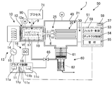
- the figure which shows the structure of the gas analyzer. A free chart showing an overview of controlling the plasma floating potential of a gas analyzer.
- FIG. 1 shows an example of a gas analyzer including a plasma generator (plasma generation unit).
- the gas analyzer 1 functions as a process monitoring device (process monitor) 50 that monitors the process by analyzing the sample gas supplied from the process.
- the gas analyzer 1 controls a plasma generation unit 10 that converts a sample gas (sampling gas, gas sample) from a process into plasma, an analysis unit (analyzer) 21 that analyzes the sample gas via the generated plasma, and a control. It includes a unit (control device, control system) 51 and an exhaust system 60.
- FIG. 2 shows in more detail the configuration of the gas analyzer 1 that functions as the process monitor 50.
- the gas analyzer 1 analyzes the sample gas 9 supplied from the process chamber 71 in which the plasma process is carried out.
- the plasma process performed in the process chamber 71 is typically a step of forming various types of films or layers on the substrate or a step of etching the substrate, and is CVD (Chemical Vapor Deposition). Or PVD (Physical Vapor Deposition) is included.
- the plasma process may be a process of laminating various types of thin films on an optical component such as a lens or a filter as a substrate.
- the process monitor 50 includes a gas analyzer 1 that analyzes the gas (sample gas) 9 supplied from the process chamber 71.
- the gas analyzer 1 includes a plasma generation unit (plasma generation device) 10 that generates plasma 19 of the sample gas 9 to be measured supplied from the process, and a sampling unit that supplies the sample gas 9 to be measured to the plasma generation device 10. It includes a (sampling device) 90 and an analysis unit 21 that analyzes the sample gas 9 via the generated plasma 19.
- the plasma generator 10 includes a dielectric wall structure 12a, a chamber (sampling chamber) 12 into which only the sample gas 9 to be measured supplied via the sampling device 90 flows in, and a dielectric wall structure 12a.
- the plasma 19 is generated by the high frequency supply mechanism (RF supply mechanism, RF supply device) 13 that generates the plasma 19 in the sampling chamber 12 decompressed by the high frequency electric field and / or the magnetic field through the sampling chamber 12, and the control electrode 17 in the sampling chamber 12.
- a floating potential supply mechanism (floating potential control mechanism, floating potential supply device) 16 for controlling the potential (suspended potential) Vf of the above is included.
- the gas analyzer 1 of this example is a mass spectrometric type, and the analysis unit (analyzer) 21 mass-charges the ionized sample gas (sample gas ion) 8 generated as plasma 19 by the plasma generator 10.
- a filter unit (filter, quadrupole filter in this example) 20 that filters by ratio, a focus electrode (ion attraction optical system) 25 that draws a part of plasma 19 as an ion flow 8, and filtered ions are detected. It has a detector unit (detector) 30 and a vacuum container (housing) 40 in which the analysis unit 21 is housed.
- the gas analyzer 1 includes an exhaust system 60 that maintains the inside of the housing 40 under appropriate negative pressure conditions (vacuum conditions).
- the exhaust system 60 of this example includes a turbo molecular pump (TMP) 61 and a roots pump 62.
- TMP turbo molecular pump
- the exhaust system 60 is a dual type that also controls the internal pressure of the sampling chamber 12 of the plasma generator 10 by using an intermediate negative pressure formed between the TMP 61 and the roots pump 62.
- the chamber 12 is designed for the purpose of generating microplasma in the intermediate region, which is neither macroplasma nor nanoplasma.
- An example of the microplasma 19 is a plasma that spreads in a region having a size of about several mm to about 100 ⁇ m. Further, in order to generate a plasma 19 having a size of this size, the plasma generation unit 10 does not use an assist gas (support gas) such as argon gas, and uses only the sample gas 9 as a plasma for analysis. 19 is generated.
- the wall body 12a of the sampling chamber 12 is composed of a dielectric member (dielectric material), and an example thereof is for plasma such as quartz (Quartz), aluminum oxide (Al 2 O 3 ) and silicon nitride (SiN 3). On the other hand, it is a highly durable dielectric.
- the sampling chamber 12 is a small chamber suitable for generating the microplasma 19, and for example, the sampling chamber 12 may have a total length of 1-100 mm and a diameter of 1-100 mm. The total length and diameter may be 5 mm or more, 10 mm or more, 80 mm or less, 50 mm or less, or 30 mm or less. Capacity of the sampling chamber 12 may also be 1 mm 3 or more, may be 10 5 mm 3 or less. The capacity of the sampling chamber 12 may be 10 mm 3 or more, 30 mm 3 or more, or 100 mm 3 or more. The capacity of the sampling chamber 12 may be 10 4 mm 3 or less, or 10 3 mm 3 or less. In a space of this size, the potential (electric field) inside the space can be easily controlled by the electrodes 17 arranged in the chamber.
- the plasma generation mechanism (RF supply mechanism) 13 of the plasma generation unit 10 uses an electric field inside the sampling chamber 12 via a dielectric wall structure 12a without using an electrode or a plasma torch. And / or a magnetic field produces plasma 19.
- An example of the RF supply mechanism 13 is a mechanism that excites the plasma 19 with high frequency (RF, Radio Frequency) power.
- Examples of the RF supply mechanism 13 include methods such as inductively coupled plasma (ICP, Inductively Coupled Plasma), dielectric barrier discharge (DBD, Dielectric Barrier Discharge), and electron cyclotron resonance (ECR, Electron Cyclotron Resonance). ..
- the plasma generation mechanism 13 of these types includes a high frequency power supply 15 and an RF field forming unit 14.
- a typical RF field forming unit 14 includes coils arranged along a typical direction of the sampling chamber 12, eg, if the sampling chamber 12 is cylindrical, one end face or diametrical direction.
- the internal pressure of the sampling chamber (container) 12 is controlled to an appropriate negative pressure by using an exhaust system 60 common to the gas analyzer 1, an independent exhaust system, or an exhaust system common to the process device.
- the internal pressure of the sampling chamber 12 may be in the range of a pressure at which microplasma 19 is likely to be generated, for example, 0.01-1 kPa.
- the internal pressure of the process chamber 71 is controlled to about 1 to several 100 Pa
- the internal pressure of the sampling chamber 12 may be controlled to a lower pressure, for example, about 0.1 to several 10 Pa, and is 0.1 Pa or more. Alternatively, it may be managed at 0.5 Pa or more, 10 Pa or less, or 5 Pa or less.
- the inside of the sampling chamber 12 may be depressurized to about 1-10 mTorr (0.13-1.3 Pa).
- the sampling chamber 12 may be depressurized to about 1-10 mTorr (0.13-1.3 Pa).
- the monitoring target is the sample gas 9 supplied from the process chamber 71 that carries out the plasma process via the sampling device 90.
- the plasma 19 can be maintained only by introducing the sample gas 9 by supplying RF power under appropriate conditions without using an arc discharge or a plasma torch.
- a support gas such as argon gas
- only the sample gas 9 can generate an ionized plasma 19 and supply it to the gas analysis unit 21. Therefore, it is possible to provide the gas analyzer 1 which has high measurement accuracy of the sample gas 9 and enables quantitative measurement of not only the gas component but also the component. Therefore, in the process monitor (process monitoring device) 50 equipped with the gas analyzer 1, the internal state of the process chamber 71 of the process device can be stably and accurately monitored for a long period of time.
- the gas analyzer 1 in order to acquire the measurement result for stable and accurate monitoring over a long period of time in the gas analyzer 1, it is also possible to generate a plasma 19 in which the floating potential Vf or the charging voltage is stable in the sampling chamber 12. is important. In this gas analyzer 1, more stable measurement is possible by controlling the floating potential of the plasma 19.
- the plasma 19 of the sample gas 9 is generated by the sampling chamber 12 dedicated to gas analysis, which is independent of the process chamber 71. Therefore, the microplasma 19 under conditions suitable for sampling and gas analysis can be generated in the sampling chamber 12 under conditions different from those of the process chamber 71. For example, even when process plasma or cleaning plasma is not generated in the process chamber 71, the internal state of the process chamber 71 can be monitored by converting the sample gas 9 into plasma.
- the sampling chamber 12 may be a small chamber (miniature chamber) having a size of, for example, several mm to several tens of mm, which is suitable for generating the microplasma 19. Since the capacity of the sampling chamber 12 is small, the entire analyzer 1 can be compactly and lightweight, and the gas analyzer 1 suitable for real-time measurement can be provided.
- the gas analyzer 1 may be a portable type or a handy type.
- the floating potential supply mechanism (supply device, floating potential control mechanism) 16 for controlling the potential (suspension potential) of the plasma 19 is a cylindrical control electrode 17 arranged along the inner surface of the sampling chamber 12 and a control electrode 17 of the control electrode 17. Includes a DC power supply 18 that controls the potential.
- the control electrode 17 may have a cylindrical shape lacking a part of the peripheral surface, and can suppress the generation of eddy currents. If there is no problem with the corrosiveness of the sample gas 9, the control electrode 17 may use a metal such as stainless steel, nickel, or molybdenum.
- a corrosion-resistant conductive material such as Hastelloy, tungsten, titanium, or carbon (graphite), which is a corrosion-resistant material, may be used.
- the sampling chamber 12 may have a cylindrical shape.
- the RF field forming unit 14 is arranged in the radial direction (first direction) orthogonal to the central axis direction (second direction) crossing the chamber 12 with respect to the cylindrical sampling chamber 12.
- An electrode (second direction) that is arranged along one end face and controls the floating potential Vf along the cylindrical inner surface in the circumferential direction (second direction) of the chamber 12 along the central axis direction (second direction).
- the first electrode) 17 is arranged.
- the RF field for forming the plasma 19 is provided by the RF field forming unit 14 arranged so as to face the openings at one end or both ends of the cylindrical control electrode 17 that controls the floating potential. Be supplied. Therefore, the interference between the field where the plasma 19 is generated and the field where the floating potential of the plasma 19 is controlled can be suppressed, the plasma 19 can be stably generated, and the floating potential can be easily controlled.
- the electrode (first electrode) 17 for controlling the floating potential Vf may have a cylindrical shape, a shape lacking a part of the cylinder, a semi-cylindrical shape, a combination of flat surfaces (flat plates), and the like. It may be.
- the potential control of the microplasma 19 is controlled by the first electrode 17 by forming the microplasma 19 so as to float in the range surrounded by the first electrode 17 by the RF field supplied by the RF field forming unit 14. It will be easy.
- the electrode 17 and the RF field forming unit 14 are arranged so as to be orthogonal to each other, and one end or both ends of the electrode 17 are arranged.
- Plasma 19 can be generated inside the electrode 17 by supplying an RF field from.
- the arrangement of the electrode 17 that controls the floating potential Vf and the RF field forming unit 14 is not limited to the above, but the arrangement of these so as to be orthogonal to each other suppresses mutual interference and efficiently generates plasma 19. , Is one of the arrangements suitable for controlling the stray potential (floating voltage) Vf of the generated plasma 19.
- the control unit (control device) 51 of the analysis unit 21 may also serve as the control unit of the analysis device 1 which is the process monitoring device 50.
- the control device 51 includes a filter control unit (filter control function, filter control device) 53 that controls the filter unit (filter) 20, and a detector control unit (detector control function, detector control) that controls the detector unit (detector) 30.
- the device) 54 and the management control device (management device, management function, management unit) 55 are included.
- the control unit 51 may include computer resources including a memory 57 and a CPU 58, and the functions of the control unit 51 may be provided by a program 59 recorded in the memory 57.
- the program (program product) 59 may be provided by recording on an appropriate recording medium.
- the analysis unit 21 of this example is a mass spectrometric type, particularly a quadrupole mass spectrometric type, and the filter unit 20 is a quadrupole filter.
- the filter control unit 53 includes a function as a drive unit (RF / DC unit) that applies high frequency and direct current to the quadrupole.
- the filter unit 20 filters the ionized sample gas (ion flow) 8 supplied as the microplasma 19 by the mass-to-charge ratio.
- the detector control unit 54 detects the components contained in the sample gas 9 by capturing the ion current generated in the detector unit (detection unit, collector unit, detector) 30, for example, the Faraday cup by the ions passing through the filter unit 20. Including functions.
- the management control device (management control unit) 55 controls the measurement (detection) mode executed by the analysis unit 21.
- the measurement modes include a mode in which the main components contained in the sample gas 9 are measured in a short time, a mode in which all the components contained in the sample gas 9 are measured in a relatively long time, and a specific one or a plurality of the sample gas 9.
- Mode to detect the component of, when a test gas whose component is known is supplied as a sample gas, the component is detected in a predetermined mode and the settings of the filter unit 20 and the detector unit 30 are changed or measured. Includes a mode to calibrate the results.
- control control unit 55 sets the ion flow 8 in the analysis unit 21. It may have a function of controlling the amount of the inflowing plasma 19 or requesting a change of the floating potential Vf of the plasma 19 so as to control the amount.
- the plasma generation control unit (plasma generation control device, generation control device) 11 that controls the plasma generation unit 10 may be a programmable control device, and the frequency of the high-voltage power supply 15 for generating the plasma 19 in the sampling chamber 12. It includes a function of controlling voltage and the like (RF control unit) 11a and a function of controlling the voltage supplied to the control electrode 17 of the floating potential supply mechanism 16 (plasma potential control unit, potential control device, voltage control device) 11b. ..
- the plasma generation control unit 11 may have a function 11c of controlling the internal pressure of the sampling chamber 12 by a pressure control valve 65 provided in a connection line with the exhaust system 60.
- sampling is performed even if the type of process executed in the process chamber 71 changes or the process state changes based on the request from the control unit 55 of the control device 51 of the analysis unit 21.
- Plasma 19 can be stably generated in the chamber 12. Therefore, the process monitoring device 50 including the analyzer 1 can continuously analyze the sample gas 9 and monitor the process.
- the potential control unit 11b controls the floating potential Vf of the plasma 19 by the first electrode 17 arranged along the inner surface of the chamber 12 so that the plasma 19 flows from the chamber 12 into the analysis unit 21 as an ion flow 8. do.
- the plasma potential (suspended potential) is suspended at a positive (positive potential, positive potential) of about +5 to 15 V with respect to the central potential of the quadrupole electric field.
- a voltage is supplied to the control electrode 17 so as to cause the control electrode 17.
- the central potential of the quadrupole is applied at + 10V or more, for example, about + 10V to 100V at the time of detecting positive ions in order to reduce noise due to detection of stray ions and stray electrons, for example.
- the floating potential of the plasma 19 as an ion source may be negatively biased with respect to the ground potential, and the Faraday cup of the detector unit 30 may be set to the ground potential.
- the potential control unit 11b is a first control unit (control device) 11x that sets the floating potential Vf so as to maintain a reference potential V0 having a predetermined potential difference ⁇ V preset with respect to the central potential of the filter unit 20.
- the second control unit (control device) 11y that fluctuates the floating potential Vf up and down so that the inflow amount of the plasma 19 into the analysis unit 21 changes depending on the analysis result or the analysis condition of the analysis unit 21 with respect to the reference potential V0.
- the potential control unit 11b maintains a reference potential V0 having a predetermined potential difference ⁇ V preset with respect to the central potential of the filter unit 20 for the floating potential Vf, and when requested, with respect to this reference potential V0.
- the floating potential Vf is configured to fluctuate up and down so that the inflow amount of the plasma 19 into the analysis unit 21 changes depending on the analysis result or the analysis condition of the analysis unit 21.
- the potential control unit 11b has the reference potential V0 by the second control function 11y.
- the floating potential Vf can be changed in the direction in which the potential difference becomes large to form a large voltage gradient with the analysis unit 21, and the inflow amount of the plasma 19 can be expanded.
- the control control unit 55 is set to the mode in which all the components contained in the sample gas 9 are measured in a relatively long time, the potential control unit 11b is set with respect to the reference potential V0 by the second control function 11y.
- the floating potential Vf may be changed in a direction in which the potential difference becomes smaller to reduce the voltage gradient with the analysis unit 21 and reduce the inflow of plasma 19 to the analysis unit 21.
- the chamber is connected to the potential control unit 11b.
- a request is made so that the floating potential Vf is such that an appropriate voltage gradient is created between the plasma 19 in the plasma 19 and the analysis unit 21, and the potential control unit 11b controls the potential of the electrode 17 to provide an appropriate floating potential.
- Vf may be set to plasma 19.
- FIG. 3 shows an outline of a method of controlling the floating potential Vf of the plasma generation device 10 of the analyzer 1 by a flowchart.
- the reference potential V0 preset in step 82 for example, +5 to 15 V with respect to the central potential of the quadrupole electric field. Set to any value in the range of degrees.
- step 83 when the filter 20 of the analysis unit (analyzer) 21 is requested to increase the inflow amount of the microplasma 19 flowing in as the ion flow 8, in step 84, the potential difference of the floating potential Vf is increased. Set (variate) the direction of expansion (growth, opening), for example, higher potential.
- step 85 when there is a request to reduce (reduce) the inflow amount of the plasma 19, in step 86, the floating potential Vf is set in a direction in which the potential difference is reduced (reduced), for example, a low potential ( To fluctuate).
- step 87 when there is a request from the management control unit 55 due to a mode change such as short-time measurement or precision measurement instead of a request indicating the inflow amount, a floating potential Vf suitable for a predetermined measurement mode is set. do.
- This control method is an example, and since the plasma generation device 10 includes a potential control mechanism (potential supply mechanism, potential supply device) 16 including an electrode 17 for floating potential control arranged in the chamber 12, the plasma The potential of the microplasma 19 supplied from the chamber 12 can be freely adjusted according to the requirements of the application using the generator 10.
- a potential control mechanism potential supply mechanism, potential supply device 16 including an electrode 17 for floating potential control arranged in the chamber 12
- the plasma The potential of the microplasma 19 supplied from the chamber 12 can be freely adjusted according to the requirements of the application using the generator 10.
- the filter unit (mass spectrometer) 20 and the detector unit (Faraday cup) 30 may be easily surrounded by a shield such as a pipe in order to prevent detection of noise components due to extra stray electrons (negative charges). ..
- the filter unit 20 may be an ion trap type or another type such as a Vienna filter.
- the filter unit 20 is not limited to the mass spectrometry type, and may be one that filters molecules or atoms of gas by using other physical quantities such as ion mobility.
- the gas analysis unit may be an optical analyzer such as a light emission analysis unit.
- microplasma is not limited to gas analysis, but can be applied to a wide variety of applications such as microfabrication, inactivation of bacteria in healthcare, etc.
- the present invention is currently being studied, and the present invention is also valid for them.
Landscapes
- Physics & Mathematics (AREA)
- Plasma & Fusion (AREA)
- Engineering & Computer Science (AREA)
- Analytical Chemistry (AREA)
- Chemical & Material Sciences (AREA)
- Spectroscopy & Molecular Physics (AREA)
- Electromagnetism (AREA)
- Other Investigation Or Analysis Of Materials By Electrical Means (AREA)
- Plasma Technology (AREA)
- Manufacturing Of Tubular Articles Or Embedded Moulded Articles (AREA)
- Investigating, Analyzing Materials By Fluorescence Or Luminescence (AREA)
- Transition And Organic Metals Composition Catalysts For Addition Polymerization (AREA)
- Chemical Vapour Deposition (AREA)
- Drying Of Semiconductors (AREA)
Priority Applications (8)
| Application Number | Priority Date | Filing Date | Title |
|---|---|---|---|
| KR1020227027035A KR102724709B1 (ko) | 2020-03-31 | 2021-03-29 | 플라즈마 생성 장치 |
| US17/912,226 US11996278B2 (en) | 2020-03-31 | 2021-03-29 | Plasma generating device |
| EP21780358.4A EP4132228A4 (en) | 2020-03-31 | 2021-03-29 | PLASMA GENERATION DEVICE |
| CN202180012025.1A CN115039516B (zh) | 2020-03-31 | 2021-03-29 | 等离子体生成装置 |
| JP2021548210A JP7039096B2 (ja) | 2020-03-31 | 2021-03-29 | ガス分析装置、プロセスモニタリング装置、ガス分析装置の制御方法 |
| JP2022031497A JP7602266B2 (ja) | 2020-03-31 | 2022-03-02 | プラズマ生成装置 |
| US18/635,131 US12400849B2 (en) | 2020-03-31 | 2024-04-15 | Plasma generating device |
| JP2024208234A JP2025032173A (ja) | 2020-03-31 | 2024-11-29 | ガス分析装置 |
Applications Claiming Priority (2)
| Application Number | Priority Date | Filing Date | Title |
|---|---|---|---|
| JP2020062862 | 2020-03-31 | ||
| JP2020-062862 | 2020-03-31 |
Related Child Applications (2)
| Application Number | Title | Priority Date | Filing Date |
|---|---|---|---|
| US17/912,226 A-371-Of-International US11996278B2 (en) | 2020-03-31 | 2021-03-29 | Plasma generating device |
| US18/635,131 Continuation US12400849B2 (en) | 2020-03-31 | 2024-04-15 | Plasma generating device |
Publications (1)
| Publication Number | Publication Date |
|---|---|
| WO2021200773A1 true WO2021200773A1 (ja) | 2021-10-07 |
Family
ID=77929449
Family Applications (1)
| Application Number | Title | Priority Date | Filing Date |
|---|---|---|---|
| PCT/JP2021/013168 Ceased WO2021200773A1 (ja) | 2020-03-31 | 2021-03-29 | プラズマ生成装置 |
Country Status (7)
| Country | Link |
|---|---|
| US (2) | US11996278B2 (https=) |
| EP (1) | EP4132228A4 (https=) |
| JP (3) | JP7039096B2 (https=) |
| KR (1) | KR102724709B1 (https=) |
| CN (1) | CN115039516B (https=) |
| TW (1) | TWI865755B (https=) |
| WO (1) | WO2021200773A1 (https=) |
Families Citing this family (2)
| Publication number | Priority date | Publication date | Assignee | Title |
|---|---|---|---|---|
| CN115039516B (zh) * | 2020-03-31 | 2024-01-02 | Atonarp株式会社 | 等离子体生成装置 |
| US20240355592A1 (en) * | 2023-04-24 | 2024-10-24 | Applied Materials, Inc. | Uniform plasma processing with a linear plasma source |
Citations (8)
| Publication number | Priority date | Publication date | Assignee | Title |
|---|---|---|---|---|
| JPH09265937A (ja) * | 1996-03-29 | 1997-10-07 | Ulvac Japan Ltd | 浮遊電位基板入射イオンのエネルギー及び質量の分析法及び装置 |
| JPH10199473A (ja) * | 1997-01-06 | 1998-07-31 | Ulvac Japan Ltd | エッチングプラズマにおける基板入射負イオンの分析法及び装置 |
| JP2006049922A (ja) * | 2005-08-24 | 2006-02-16 | Ulvac Japan Ltd | エッチング装置 |
| JP2011249289A (ja) * | 2010-05-31 | 2011-12-08 | Toyota Technological Institute | 浮遊電極を持つ誘導結合型マイクロプラズマ源 |
| JP2013161694A (ja) * | 2012-02-07 | 2013-08-19 | Toyota Gakuen | 浮遊電極の一部がガス流路内部に面している誘導結合型マイクロプラズマ源 |
| JP2015162267A (ja) * | 2014-02-26 | 2015-09-07 | 学校法人トヨタ学園 | 浮遊電極がシールドされた誘導結合型マイクロプラズマ源 |
| JP2015204418A (ja) | 2014-04-15 | 2015-11-16 | 株式会社東芝 | プラズマ処理装置及びプラズマ処理方法 |
| US20190011400A1 (en) * | 2017-07-07 | 2019-01-10 | Teknoscan Systems Inc. | Polarization dielectric discharge source for ims instrument |
Family Cites Families (23)
| Publication number | Priority date | Publication date | Assignee | Title |
|---|---|---|---|---|
| GB8813149D0 (en) * | 1988-06-03 | 1988-07-06 | Vg Instr Group | Mass spectrometer |
| US5650618A (en) | 1995-11-30 | 1997-07-22 | The Regents Of The University Of California | Compact mass spectrometer for plasma discharge ion analysis |
| JP3774525B2 (ja) * | 1997-01-06 | 2006-05-17 | 株式会社アルバック | プラズマ中の負イオン測定法及び装置 |
| JPH11158638A (ja) * | 1997-11-25 | 1999-06-15 | Kao Corp | 炭素薄膜の製造方法 |
| JP4221235B2 (ja) * | 2003-03-05 | 2009-02-12 | キヤノンアネルバ株式会社 | イオン付着質量分析方法、負イオン計測方法、および質量分析装置 |
| US7460225B2 (en) | 2004-03-05 | 2008-12-02 | Vassili Karanassios | Miniaturized source devices for optical and mass spectrometry |
| JP4865532B2 (ja) * | 2006-12-22 | 2012-02-01 | 株式会社アルバック | 質量分析ユニット、及び質量分析ユニットの使用方法 |
| JP5233131B2 (ja) * | 2007-02-23 | 2013-07-10 | 株式会社Ihi | 浸炭装置及び浸炭方法 |
| KR100891376B1 (ko) * | 2007-03-21 | 2009-04-02 | 차동호 | 셀프 플라즈마 챔버와 결합하여 플라즈마 공정장치에서공정진행상태를 실시간으로 모니터하고 이상 여부를검출하는 복합센서 |
| CN101680856A (zh) * | 2007-05-15 | 2010-03-24 | 株式会社爱发科 | 质谱分析单元 |
| KR100905128B1 (ko) * | 2008-07-29 | 2009-06-30 | 주식회사 나노텍 | 셀프 플라즈마 챔버의 오염 방지 장치 및 방법 |
| JP6087056B2 (ja) * | 2012-01-06 | 2017-03-01 | アジレント・テクノロジーズ・インクAgilent Technologies, Inc. | 誘導結合プラズマms/ms型質量分析装置 |
| JP5759036B2 (ja) * | 2014-03-06 | 2015-08-05 | 株式会社日立ハイテクノロジーズ | 質量分析装置 |
| WO2015159714A1 (ja) * | 2014-04-16 | 2015-10-22 | 株式会社日立ハイテクノロジーズ | 質量分析装置および質量分析装置に用いられるカートリッジ |
| JP6518505B2 (ja) * | 2015-05-12 | 2019-05-22 | 株式会社日立ハイテクノロジーズ | プラズマ処理装置およびプラズマ処理方法 |
| US9824941B2 (en) * | 2015-11-17 | 2017-11-21 | Lam Research Corporation | Systems and methods for detection of plasma instability by electrical measurement |
| JP6505027B2 (ja) | 2016-01-04 | 2019-04-24 | 株式会社日立ハイテクノロジーズ | 試料の離脱方法およびプラズマ処理装置 |
| JP6703425B2 (ja) * | 2016-03-23 | 2020-06-03 | 株式会社栗田製作所 | プラズマ処理方法及びプラズマ処理装置 |
| JP6888455B2 (ja) * | 2017-07-21 | 2021-06-16 | 三菱ケミカル株式会社 | ガスバリア性プラスチック容器の製造方法 |
| KR102023705B1 (ko) * | 2018-01-30 | 2019-09-20 | 한국기계연구원 | 공정 모니터링을 위한 플라즈마 반응기 |
| KR102046637B1 (ko) * | 2018-01-30 | 2019-11-19 | 한국기계연구원 | 공정 모니터링을 위한 플라즈마 반응기 |
| CN115039516B (zh) * | 2020-03-31 | 2024-01-02 | Atonarp株式会社 | 等离子体生成装置 |
| JP7343944B2 (ja) * | 2021-01-29 | 2023-09-13 | アトナープ株式会社 | ガス分析装置および制御方法 |
-
2021
- 2021-03-29 CN CN202180012025.1A patent/CN115039516B/zh active Active
- 2021-03-29 KR KR1020227027035A patent/KR102724709B1/ko active Active
- 2021-03-29 JP JP2021548210A patent/JP7039096B2/ja active Active
- 2021-03-29 EP EP21780358.4A patent/EP4132228A4/en active Pending
- 2021-03-29 US US17/912,226 patent/US11996278B2/en active Active
- 2021-03-29 WO PCT/JP2021/013168 patent/WO2021200773A1/ja not_active Ceased
- 2021-03-30 TW TW110111456A patent/TWI865755B/zh active
-
2022
- 2022-03-02 JP JP2022031497A patent/JP7602266B2/ja active Active
-
2024
- 2024-04-15 US US18/635,131 patent/US12400849B2/en active Active
- 2024-11-29 JP JP2024208234A patent/JP2025032173A/ja active Pending
Patent Citations (8)
| Publication number | Priority date | Publication date | Assignee | Title |
|---|---|---|---|---|
| JPH09265937A (ja) * | 1996-03-29 | 1997-10-07 | Ulvac Japan Ltd | 浮遊電位基板入射イオンのエネルギー及び質量の分析法及び装置 |
| JPH10199473A (ja) * | 1997-01-06 | 1998-07-31 | Ulvac Japan Ltd | エッチングプラズマにおける基板入射負イオンの分析法及び装置 |
| JP2006049922A (ja) * | 2005-08-24 | 2006-02-16 | Ulvac Japan Ltd | エッチング装置 |
| JP2011249289A (ja) * | 2010-05-31 | 2011-12-08 | Toyota Technological Institute | 浮遊電極を持つ誘導結合型マイクロプラズマ源 |
| JP2013161694A (ja) * | 2012-02-07 | 2013-08-19 | Toyota Gakuen | 浮遊電極の一部がガス流路内部に面している誘導結合型マイクロプラズマ源 |
| JP2015162267A (ja) * | 2014-02-26 | 2015-09-07 | 学校法人トヨタ学園 | 浮遊電極がシールドされた誘導結合型マイクロプラズマ源 |
| JP2015204418A (ja) | 2014-04-15 | 2015-11-16 | 株式会社東芝 | プラズマ処理装置及びプラズマ処理方法 |
| US20190011400A1 (en) * | 2017-07-07 | 2019-01-10 | Teknoscan Systems Inc. | Polarization dielectric discharge source for ims instrument |
Non-Patent Citations (1)
| Title |
|---|
| See also references of EP4132228A4 |
Also Published As
| Publication number | Publication date |
|---|---|
| CN115039516A (zh) | 2022-09-09 |
| JP7602266B2 (ja) | 2024-12-18 |
| JPWO2021200773A1 (https=) | 2021-10-07 |
| JP2022075719A (ja) | 2022-05-18 |
| KR102724709B1 (ko) | 2024-10-30 |
| TW202139286A (zh) | 2021-10-16 |
| US20240258092A1 (en) | 2024-08-01 |
| JP7039096B2 (ja) | 2022-03-22 |
| CN115039516B (zh) | 2024-01-02 |
| JP2025032173A (ja) | 2025-03-11 |
| US20230187195A1 (en) | 2023-06-15 |
| EP4132228A4 (en) | 2024-05-15 |
| US11996278B2 (en) | 2024-05-28 |
| KR20220123459A (ko) | 2022-09-06 |
| US12400849B2 (en) | 2025-08-26 |
| EP4132228A1 (en) | 2023-02-08 |
| TWI865755B (zh) | 2024-12-11 |
Similar Documents
| Publication | Publication Date | Title |
|---|---|---|
| JP6783496B1 (ja) | ガス分析装置 | |
| JP2025032173A (ja) | ガス分析装置 | |
| JP6976628B2 (ja) | ガス分析装置及びガス分析装置の制御方法 | |
| KR101591961B1 (ko) | 플라즈마 처리 챔버의 플라즈마 상태 분석 장치 및 방법 | |
| JP2025026477A (ja) | ガス分析装置および制御方法 | |
| JP2022075719A5 (https=) | ||
| Toader et al. | Characterization of a high-density, direct-current reflex discharge plasma source operating in Ar and N 2 |
Legal Events
| Date | Code | Title | Description |
|---|---|---|---|
| ENP | Entry into the national phase |
Ref document number: 2021548210 Country of ref document: JP Kind code of ref document: A |
|
| 121 | Ep: the epo has been informed by wipo that ep was designated in this application |
Ref document number: 21780358 Country of ref document: EP Kind code of ref document: A1 |
|
| ENP | Entry into the national phase |
Ref document number: 20227027035 Country of ref document: KR Kind code of ref document: A |
|
| NENP | Non-entry into the national phase |
Ref country code: DE |
|
| ENP | Entry into the national phase |
Ref document number: 2021780358 Country of ref document: EP Effective date: 20221027 |