WO2021200023A1 - 撮影支援装置、その作動方法、及び作動プログラム - Google Patents
撮影支援装置、その作動方法、及び作動プログラム Download PDFInfo
- Publication number
- WO2021200023A1 WO2021200023A1 PCT/JP2021/009922 JP2021009922W WO2021200023A1 WO 2021200023 A1 WO2021200023 A1 WO 2021200023A1 JP 2021009922 W JP2021009922 W JP 2021009922W WO 2021200023 A1 WO2021200023 A1 WO 2021200023A1
- Authority
- WO
- WIPO (PCT)
- Prior art keywords
- image
- radiation
- subject
- ray
- shooting
- Prior art date
- Legal status (The legal status is an assumption and is not a legal conclusion. Google has not performed a legal analysis and makes no representation as to the accuracy of the status listed.)
- Ceased
Links
Images







Classifications
-
- A—HUMAN NECESSITIES
- A61—MEDICAL OR VETERINARY SCIENCE; HYGIENE
- A61B—DIAGNOSIS; SURGERY; IDENTIFICATION
- A61B5/00—Measuring for diagnostic purposes; Identification of persons
- A61B5/0059—Measuring for diagnostic purposes; Identification of persons using light, e.g. diagnosis by transillumination, diascopy, fluorescence
- A61B5/0077—Devices for viewing the surface of the body, e.g. camera, magnifying lens
-
- A—HUMAN NECESSITIES
- A61—MEDICAL OR VETERINARY SCIENCE; HYGIENE
- A61B—DIAGNOSIS; SURGERY; IDENTIFICATION
- A61B5/00—Measuring for diagnostic purposes; Identification of persons
- A61B5/0033—Features or image-related aspects of imaging apparatus, e.g. for MRI, optical tomography or impedance tomography apparatus; Arrangements of imaging apparatus in a room
- A61B5/0035—Features or image-related aspects of imaging apparatus, e.g. for MRI, optical tomography or impedance tomography apparatus; Arrangements of imaging apparatus in a room adapted for acquisition of images from more than one imaging mode, e.g. combining MRI and optical tomography
-
- A—HUMAN NECESSITIES
- A61—MEDICAL OR VETERINARY SCIENCE; HYGIENE
- A61B—DIAGNOSIS; SURGERY; IDENTIFICATION
- A61B5/00—Measuring for diagnostic purposes; Identification of persons
- A61B5/74—Details of notification to user or communication with user or patient; User input means
- A61B5/742—Details of notification to user or communication with user or patient; User input means using visual displays
- A61B5/7425—Displaying combinations of multiple images regardless of image source, e.g. displaying a reference anatomical image with a live image
-
- A—HUMAN NECESSITIES
- A61—MEDICAL OR VETERINARY SCIENCE; HYGIENE
- A61B—DIAGNOSIS; SURGERY; IDENTIFICATION
- A61B5/00—Measuring for diagnostic purposes; Identification of persons
- A61B5/74—Details of notification to user or communication with user or patient; User input means
- A61B5/742—Details of notification to user or communication with user or patient; User input means using visual displays
- A61B5/743—Displaying an image simultaneously with additional graphical information, e.g. symbols, charts, function plots
-
- A—HUMAN NECESSITIES
- A61—MEDICAL OR VETERINARY SCIENCE; HYGIENE
- A61B—DIAGNOSIS; SURGERY; IDENTIFICATION
- A61B6/00—Apparatus or devices for radiation diagnosis; Apparatus or devices for radiation diagnosis combined with radiation therapy equipment
- A61B6/08—Auxiliary means for directing the radiation beam to a particular spot, e.g. using light beams
-
- A—HUMAN NECESSITIES
- A61—MEDICAL OR VETERINARY SCIENCE; HYGIENE
- A61B—DIAGNOSIS; SURGERY; IDENTIFICATION
- A61B6/00—Apparatus or devices for radiation diagnosis; Apparatus or devices for radiation diagnosis combined with radiation therapy equipment
- A61B6/44—Constructional features of apparatus for radiation diagnosis
- A61B6/4417—Constructional features of apparatus for radiation diagnosis related to combined acquisition of different diagnostic modalities
-
- A—HUMAN NECESSITIES
- A61—MEDICAL OR VETERINARY SCIENCE; HYGIENE
- A61B—DIAGNOSIS; SURGERY; IDENTIFICATION
- A61B6/00—Apparatus or devices for radiation diagnosis; Apparatus or devices for radiation diagnosis combined with radiation therapy equipment
- A61B6/54—Control of apparatus or devices for radiation diagnosis
-
- A—HUMAN NECESSITIES
- A61—MEDICAL OR VETERINARY SCIENCE; HYGIENE
- A61B—DIAGNOSIS; SURGERY; IDENTIFICATION
- A61B6/00—Apparatus or devices for radiation diagnosis; Apparatus or devices for radiation diagnosis combined with radiation therapy equipment
- A61B6/54—Control of apparatus or devices for radiation diagnosis
- A61B6/542—Control of apparatus or devices for radiation diagnosis involving control of exposure
-
- A—HUMAN NECESSITIES
- A61—MEDICAL OR VETERINARY SCIENCE; HYGIENE
- A61B—DIAGNOSIS; SURGERY; IDENTIFICATION
- A61B6/00—Apparatus or devices for radiation diagnosis; Apparatus or devices for radiation diagnosis combined with radiation therapy equipment
- A61B6/58—Testing, adjusting or calibrating thereof
- A61B6/587—Alignment of source unit to detector unit
-
- A—HUMAN NECESSITIES
- A61—MEDICAL OR VETERINARY SCIENCE; HYGIENE
- A61B—DIAGNOSIS; SURGERY; IDENTIFICATION
- A61B2505/00—Evaluating, monitoring or diagnosing in the context of a particular type of medical care
- A61B2505/09—Rehabilitation or training
-
- A—HUMAN NECESSITIES
- A61—MEDICAL OR VETERINARY SCIENCE; HYGIENE
- A61B—DIAGNOSIS; SURGERY; IDENTIFICATION
- A61B6/00—Apparatus or devices for radiation diagnosis; Apparatus or devices for radiation diagnosis combined with radiation therapy equipment
- A61B6/04—Positioning of patients; Tiltable beds or the like
-
- A—HUMAN NECESSITIES
- A61—MEDICAL OR VETERINARY SCIENCE; HYGIENE
- A61B—DIAGNOSIS; SURGERY; IDENTIFICATION
- A61B6/00—Apparatus or devices for radiation diagnosis; Apparatus or devices for radiation diagnosis combined with radiation therapy equipment
- A61B6/42—Arrangements for detecting radiation specially adapted for radiation diagnosis
- A61B6/4208—Arrangements for detecting radiation specially adapted for radiation diagnosis characterised by using a particular type of detector
- A61B6/4233—Arrangements for detecting radiation specially adapted for radiation diagnosis characterised by using a particular type of detector using matrix detectors
-
- A—HUMAN NECESSITIES
- A61—MEDICAL OR VETERINARY SCIENCE; HYGIENE
- A61B—DIAGNOSIS; SURGERY; IDENTIFICATION
- A61B6/00—Apparatus or devices for radiation diagnosis; Apparatus or devices for radiation diagnosis combined with radiation therapy equipment
- A61B6/44—Constructional features of apparatus for radiation diagnosis
- A61B6/4405—Constructional features of apparatus for radiation diagnosis the apparatus being movable or portable, e.g. handheld or mounted on a trolley
-
- A—HUMAN NECESSITIES
- A61—MEDICAL OR VETERINARY SCIENCE; HYGIENE
- A61B—DIAGNOSIS; SURGERY; IDENTIFICATION
- A61B6/00—Apparatus or devices for radiation diagnosis; Apparatus or devices for radiation diagnosis combined with radiation therapy equipment
- A61B6/44—Constructional features of apparatus for radiation diagnosis
- A61B6/4429—Constructional features of apparatus for radiation diagnosis related to the mounting of source units and detector units
- A61B6/4464—Constructional features of apparatus for radiation diagnosis related to the mounting of source units and detector units the source unit or the detector unit being mounted to ceiling
-
- A—HUMAN NECESSITIES
- A61—MEDICAL OR VETERINARY SCIENCE; HYGIENE
- A61B—DIAGNOSIS; SURGERY; IDENTIFICATION
- A61B6/00—Apparatus or devices for radiation diagnosis; Apparatus or devices for radiation diagnosis combined with radiation therapy equipment
- A61B6/58—Testing, adjusting or calibrating thereof
- A61B6/588—Setting distance between source unit and detector unit
-
- A—HUMAN NECESSITIES
- A61—MEDICAL OR VETERINARY SCIENCE; HYGIENE
- A61B—DIAGNOSIS; SURGERY; IDENTIFICATION
- A61B6/00—Apparatus or devices for radiation diagnosis; Apparatus or devices for radiation diagnosis combined with radiation therapy equipment
- A61B6/58—Testing, adjusting or calibrating thereof
- A61B6/589—Setting distance between source unit and patient
Definitions
- the technology of the present disclosure relates to a shooting support device, an operation method thereof, and an operation program.
- a radiological technologist or a doctor positions the imaging site of the subject, and then radiological imaging is performed based on the instructions of the technologist or the like. ..
- the moving subject may cause the imaging region to shift in position, and an image of the desired imaging region may not be obtained.
- imaging the failure to obtain a desired radiographic image by radiography, that is, the failure of radiography, is referred to as "imaging.” If there is a photo loss, re-shooting will be performed.
- an engineer or the like may mistakenly determine that a radiographic image that does not require re-imaging is a copying loss, so that unnecessary re-imaging may be performed. Re-shooting takes time and effort, and the amount of exposure to the subject increases, so it is better to reduce the amount.
- Japanese Patent Application Laid-Open No. 2008-206740 describes an optical image of an exposed region in which a subject is irradiated with radiation during the generation of radiation by a radiation generating unit (hereinafter referred to as an optical image).
- a radiography system provided with an optical camera that captures an image is disclosed.
- an optical image captured at the same time as a radiographic image of a subject was imaged in the past is stored, and the position of the subject in the past optical image is stored. , The amount of deviation from the position of the subject in the current optical image is calculated.
- the position of the subject when a new subject is imaged can be aligned by using the image content of the optical image.
- Japanese Patent Application Laid-Open No. 6-217973 discloses an X-ray imaging apparatus provided with an optical camera that captures a surface image (hereinafter, also referred to as an optical image) of a subject including an X-ray irradiation field. There is.
- the timing control unit determines the timing of saving the X-ray image and the surface image in response to the exposure signal from the X-ray control unit. It is controlled and the X-ray image and the surface image related to the same target part are stored in each frame memory in relation to each other.
- the joint cavity (gap between bones) needs to be clearly depicted in the radiographic image.
- radiation is a line bundle that radiates from the focal point of the radiation source, the incident angle of radiation changes due to a slight misalignment of the joint, and the depiction of the joint cavity becomes unclear. If the depiction of the joint cavity is unclear, the image will be lost and re-imaging will be required.
- an engineer or the like repositions the subject by referring to an optical image captured at the same time as a radiographic image in the past. It can be performed. In order to accurately position the subject, the optical image must be captured at the same time as the radiographic image that was lost. In particular, as described above, when the knee joint is used as the imaging site, a slight misalignment of the subject causes image loss. Therefore, the optical image and the radiographic image are captured at the same time as possible. Is desirable.
- Japanese Unexamined Patent Publication No. 2008-206740 describes that an optical image captured at the same time as a radiographic image of a subject is imaged is stored. It is not stated whether to acquire at the same time.
- Japanese Patent Application Laid-Open No. 6-217973 describes that the timing of saving the X-ray image and the surface image is controlled in response to the exposure signal from the X-ray control unit.
- the exposure signal is output by pressing the exposure switch. Therefore, there is a time lag between the output of the exposure signal from the X-ray control unit and the actual emission of X-rays from the X-ray tube.
- an X-ray film is used as a radiation detector.
- an electronic cassette is used instead of the X-ray film, there may be a further time lag between the time when the exposure switch is pressed and the time when the electronic cassette side completes the preparation for radiation detection.
- An object of the technique of the present disclosure is to provide an imaging support device, an operation method thereof, and an operation program capable of reducing a difference in acquisition time between a radiographic image and an optical image.
- the photographing support device of the present disclosure includes a radiation source and a radiation image detector that detects a radiation image of the subject based on the radiation emitted from the radiation source and transmitted through the subject.
- An optical camera that outputs an optical image by optically photographing an area including an irradiation field of radiation emitted from a radiation source to a subject, and at least one processor.
- the processor associates the optical image acquired by the optical camera with the radiation image based on the timing signal transmitted from the radiation image detector side.
- the timing signal is preferably an irradiation start detection signal output from a radiation image detector having a radiation irradiation start detection function.
- the timing signal is preferably a radiation detection signal output from an automatic exposure controller provided separately from the radiation image detector.
- the timing signal is preferably a ready signal that is output when the radiation image detector is ready to detect radiation.
- the optical camera is a moving image shooting device that acquires an optical image for each frame and outputs a moving image composed of a plurality of acquired frames
- the processor is based on a timing signal transmitted from the radiation image detector side. , It is preferable to extract one frame from the moving image and associate the extracted frame with the radiographic image.
- the processor preferably discards frames other than the extracted frame.
- the processor associates patient information with the associated optical image and radiographic image and outputs the patient information to the outside.
- the method of operating the imaging support device of the present disclosure is used in a radiographic apparatus having a radioactive source and a radiographic image detector that detects a radiographic image of the subject based on the radiation emitted from the radioactive source and transmitted through the subject.
- This is a method of operating an imaging support device including an optical camera that outputs an optical image by optically photographing an area including an irradiation field of radiation emitted from a source to a subject, and is transmitted from the radiation image detector side. Based on the timing signal, the optical image acquired by the optical camera is associated with the radiographic image.
- the operation program of the present disclosure is used in a radiographing apparatus having a radiation source and a radiation image detector that detects a radiation image of the subject based on the radiation emitted from the radiation source and transmitted through the subject, and is used from the radiation source to the subject.
- An operation program that operates an imaging support device including an optical camera that outputs an optical image by optically photographing an area including an irradiation field of the irradiated radiation and at least one processor, and is a radiation image detector. Based on the timing signal transmitted from the side, the processor is made to perform an operation of associating the optical image acquired by the optical camera with the radiation image.
- an imaging support device capable of reducing a difference in acquisition time between a radiographic image and an optical image, an operation method thereof, and an operation program.
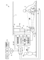
- FIG. 1 shows the configuration of an X-ray imaging system 10 that uses X-rays as radiation.
- the X-ray imaging system 10 that uses X-rays as radiation includes an X-ray source 11, a radiation source control device 12, an electronic cassette 13, a console 14, and an optical camera 15.
- the shooting support device is configured by the console 14 and the optical camera 15.
- the X-ray source 11 is an example of a radiation source.
- the electronic cassette 13 is an example of a radiographic image detector.
- the electronic cassette 13 is arranged at a position facing the X-ray source 11.
- the subject H By arranging the subject H between the X-ray source 11 and the electronic cassette 13, it is possible to take an X-ray image of the imaging portion (knee in FIG. 1) of the subject H.
- the X-ray source 11 and the electronic cassette 13 constitute an X-ray imaging apparatus.
- This X-ray imaging apparatus is an example of a radiographic imaging apparatus according to the technique of the present disclosure.
- the electronic cassette 13 may be arranged on a standing shooting table or a lying shooting table.
- the radiologist hereinafter, simply referred to as a technician
- a technician positions the subject H, and then the radiologist RG performs an X-ray imaging operation.
- the X-ray source 11 includes an X-ray tube 11A that generates X-rays and an irradiation field limiter 11B that limits the irradiation field RF, which is a region where X-rays are irradiated.
- the X-ray source 11 may include an irradiation field display light source (not shown) that emits irradiation field display light indicating the irradiation field RF on the X-ray incident surface 13A of the electronic cassette 13.
- the X-ray tube 11A has a filament that emits thermoelectrons and a target that the thermoelectrons emitted from the filament collide with each other to emit X-rays.
- the irradiation field limiter 11B for example, by arranging four lead plates that shield X-rays on each side of the quadrangle, a quadrangular irradiation opening for transmitting X-rays is formed in the center. In this case, the irradiation field limiting device 11B changes the size of the irradiation opening by moving the position of the lead plate, and sets the irradiation field RF.
- the radiation source control device 12 has a touch panel 12A, a voltage generation unit 12B, and a control unit 12C.
- the touch panel 12A is operated by the engineer RG when setting the X-ray irradiation conditions and the size of the irradiation opening of the irradiation field limiting device 11B.
- the X-ray irradiation conditions include the tube voltage applied to the X-ray source 11, the tube current, and the X-ray irradiation time.
- the voltage generating unit 12B generates a tube voltage to be applied to the X-ray tube 11A.
- the control unit 12C sets the tube voltage, the tube current, and the X-ray irradiation time to the values set by the touch panel 12A.
- the control unit 12C has a timer that starts timing when X-rays are generated from the X-ray tube 11A.
- the control unit 12C stops the operation of the X-ray tube 11A, for example, when the time measured by the timer reaches the irradiation time specified by the irradiation conditions. Further, the control unit 12C operates the irradiation field limiting device 11B, and sets the size of the irradiation opening to the size set by the touch panel 12A.
- the irradiation switch 16 is connected to the control unit 12C via a cable or the like.
- the irradiation switch 16 is operated by the engineer RG when starting the irradiation of X-rays.
- the radiation source control device 12 When the irradiation switch 16 is operated, the radiation source control device 12 generates X-rays in the X-ray tube 11A. As a result, X-rays are irradiated toward the irradiation field RF.
- the electronic cassette 13 detects an X-ray image XP based on X-rays emitted from the X-ray source 11 and transmitted through the imaged portion of the subject H.
- the electronic cassette 13 has a wireless communication unit and a battery, and operates wirelessly.
- the electronic cassette 13 wirelessly transmits the detected X-ray image XP to the console 14.
- the X-ray image XP is an example of a radiographic image.
- the electronic cassette 13 of the present embodiment is not a synchronous type that starts operation in response to receiving a control signal from the console 14, but detects X-rays emitted from the X-ray source 11 and automatically controls the operation.
- Asynchronous type synchronous free type
- the electronic cassette 13 has an irradiation start detection function for detecting that X-ray irradiation has been started by detecting X-rays emitted from the X-ray source 11. Further, when the electronic cassette 13 detects the start of X-ray irradiation, the electronic cassette 13 wirelessly transmits the irradiation start detection signal SI to the console 14.
- the irradiation start detection signal SI is an example of a timing signal according to the technique of the present disclosure.
- the X-ray source 11 is suspended vertically downward from the ceiling 2 of the photographing room.
- the X-ray source 11 is held by the suspension holding mechanism 17.
- the suspension holding mechanism 17 is attached to the ceiling 2 via the horizontal moving mechanism 18.
- the suspension holding mechanism 17 holds the X-ray source 11 so as to be able to move up and down in the vertical direction ( ⁇ Z direction).
- the horizontal movement mechanism 18 movably holds the suspension holding mechanism 17 in the X-irradiation axis direction ( ⁇ X direction) and the direction orthogonal to the X irradiation axis direction ( ⁇ Y direction) of the X-ray source 11.
- Motors (not shown) are provided in the suspension holding mechanism 17 and the horizontal moving mechanism 18, respectively, and it is possible to move the X-ray source 11 manually or electrically in each direction.
- the operations of the suspension holding mechanism 17 and the horizontal moving mechanism 18 are controlled by the control unit 12C. Whether to move the X-ray source 11 manually or electrically can be selected by the touch panel 12A. By moving the X-ray source 11, the position of the irradiation field RF can be adjusted.
- the optical camera 15 is an optical digital camera including a CMOS (Complementary Metal Oxide Semiconductor) type image sensor, a CCD (Charge Coupled Device) type image sensor, and the like, and performs photographing based on visible light as an example. ..
- the optical camera 15 enables still image shooting and moving image shooting.
- the optical camera 15 is an example of a moving image capturing device according to the technique of the present disclosure.
- the optical axis of the optical camera 15 is parallel to the irradiation axis of X-rays passing through the center of the irradiation field RF.
- the optical camera 15 generates an optical image by optically photographing a region including the irradiation field RF.
- the optical image is an image showing an imaged portion of the subject H located in the irradiation field RF.
- the optical image is, for example, a color still image or moving image.
- the optical camera 15 is attached to the outer peripheral portion of the X-ray source 11.
- the optical camera 15 may not be attached to the outer peripheral portion of the X-ray source 11, or may be built in the X-ray source 11. Further, in the optical camera 15, the objective lens and the image pickup element may be formed separately. In this case, even if the objective lens is arranged on the outer peripheral portion of the X-ray source 11 and the image sensor is built in a portion other than the X-ray source 11 (for example, an arm supporting the X-ray source 11). good.
- the optical camera 15 is connected to the console 14 by wire or wirelessly.
- the console 14 controls the shooting operation of the optical camera 15 by functioning as a shooting control device.
- the console 14 causes the optical camera 15 to shoot a still image in conjunction with the irradiation start detection signal SI transmitted from the electronic cassette 13, and also causes the optical camera 15 to shoot a moving image during the shooting preparation period before the start of X-ray shooting.
- the console 14 is installed in an operation room adjacent to a photographing room in which the X-ray source 11 is installed.
- the console 14 When the console 14 receives the irradiation start detection signal SI from the electronic cassette 13, it transmits a still image shooting instruction signal to the optical camera 15.
- the optical camera 15 captures a still image of a region including the irradiation field RF in response to a still image capture instruction signal input from the console 14.
- the optical image (hereinafter, referred to as still image SP) obtained by this still image shooting is transmitted to the console 14.
- the console 14 transmits a moving image shooting start signal to the optical camera 15 when the engineer RG performs an operation to start shooting preparation.
- the optical camera 15 starts moving image shooting in the region including the irradiation field RF in response to the moving image shooting start signal input from the console 14.
- the optical image (hereinafter referred to as a moving image MP) obtained by this moving image shooting is transmitted to the console 14 as a so-called live view image in real time at the time of moving image shooting.
- the console 14 is connected to the RIS (Radiology Information System), the PACS (Picture Archiving and Communication System), and the photo loss management system 19 provided in the X-ray imaging system 10 via the network N.
- the console 14 has a function of performing X-ray photography by the operation of the engineer RG based on the photographing order and various information acquired from the RIS. Further, the console 14 has a function of transmitting the X-ray image XP received from the electronic cassette 13 to the PACS after the X-ray imaging.
- the console 14 has a function of transmitting the X-ray image XP determined by the engineer RG to the copying loss management system 19 after the X-ray shooting.
- the copying loss management system 19 collects the X-ray image XP determined to be copying loss and analyzes the cause of the copying loss.
- FIG. 2 shows the configuration of the electronic cassette 13.
- the electronic cassette 13 includes a sensor panel 20, a circuit unit 21, and a rectangular parallelepiped-shaped portable housing 22 that accommodates the sensor panel 20.
- the housing 22 has a size conforming to the international standard ISO (International Organization for Standardization) 4090: 2001, which is substantially the same as, for example, a film cassette, an IP (Imaging Plate) cassette, and a CR (Computed Radiography) cassette.
- ISO International Organization for Standardization
- the electronic cassette 13 is positioned so that the X-ray incident surface 13A, which is the upper surface of the housing 22, faces the X-ray source 11, and the X-ray incident surface 13A is irradiated with X-rays.
- the housing 22 also informs the operating state of the electronic cassette 13 such as a switch for switching the main power on / off, the remaining battery usage time, and the shooting ready state. An indicator is provided.
- the sensor panel 20 is composed of a scintillator 20A and a photodetector substrate 20B.
- the scintillator 20A and the photodetector substrate 20B are laminated in the order of the scintillator 20A and the photodetector substrate 20B when viewed from the X-ray incident surface 13A side.
- the scintillator 20A has a phosphor such as CsI: Tl (thallium-activated cesium iodide) or GOS (Gd 2 O 2 S: Tb, terbium-activated gadolinium oxysulfide), and X is incident through the X-ray incident surface 13A. Converts the line into visible light and emits it.
- a sensor panel in which the photodetector substrate 20B and the scintillator 20A are laminated in this order when viewed from the X-ray incident surface 13A side may be used. Further, a direct conversion type sensor panel that directly converts X-rays into signal charges by a photoconductive film such as amorphous selenium may be used.
- the photodetector substrate 20B detects visible light emitted from the scintillator 20A and converts it into electric charges.
- the circuit unit 21 controls the drive of the photodetection board 20B and generates an X-ray image XP based on the electric charge output from the photodetection board 20B.
- FIG. 3 shows the configuration of the photodetector substrate 20B.
- the optical detection substrate 20B includes a pixel region 30, a gate driver 31, a signal processing circuit 32, an irradiation start detection unit 33, a control unit 34, and a communication interface (I / F) 35.
- the pixel region 30 has a plurality of normal pixels 40A arranged on a matrix along the X and Y directions orthogonal to each other.
- the normal pixel 40A is a pixel for generating an X-ray image for detecting X-rays and generating an X-ray image XP.
- a detection pixel 40B is provided in the pixel area 30, in addition to the normal pixel 40A.
- the detection pixel 40B is a pixel for detecting the start of irradiation for detecting the start of irradiation of X-rays.
- the normal pixel 40A has a photoelectric conversion unit 41 that generates and stores electric charges by photoelectric conversion of visible light converted by a scintillator, and a TFT 42 as a switching element.
- the photoelectric conversion unit 41 has, for example, a PIN (p-intrinsic-n) type semiconductor layer, an upper electrode arranged on the upper side of the semiconductor layer, and a lower electrode arranged on the lower side of the semiconductor layer. A bias voltage is applied to the upper electrode.
- the lower electrode is connected to a TFT (Thin Film Transistor) 42.
- the detection pixel 40B has a photoelectric conversion unit 41 and a TFT 42, similarly to the normal pixel 40A. However, in the detection pixel 40B, the source electrode and the drain electrode of the TFT 42 are short-circuited. Hereinafter, when it is not necessary to distinguish between the normal pixel 40A and the detection pixel 40B, these are simply referred to as the pixel 40.
- the pixel region 30 has a plurality of scanning lines 43 extending in the X direction and a plurality of signal lines 44 extending in the Y direction.
- the scanning line 43 and the signal line 44 are wired in a grid pattern.
- the pixels 40 are connected to the intersections of the scanning line 43 and the signal line 44, respectively.
- the gate electrode of the TFT 42 is connected to the scanning line 43
- the source electrode of the TFT 42 is connected to the signal line 44.
- the drain electrode of the TFT 42 is connected to the photoelectric conversion unit 41.
- Each scanning line 43 is commonly connected to the pixel 40 for one pixel line.
- Each signal line 44 is commonly connected to pixels 40 for one pixel row.
- Each scanning line 43 is connected to a gate driver 31.
- Each signal line 44 is connected to a signal processing circuit 32.
- the gate driver 31 sequentially supplies gate pulses as scanning signals to each scanning line 43.
- the gate pulse supplied to the scanning line 43 is applied to the gate electrode of the TFT 42 included in the pixel 40 connected to the scanning line 43.
- the electric charge accumulated in the photoelectric conversion unit 41 of the normal pixel 40A is output to the signal line 44 when the TFT 42 is turned on. Since the source electrode and the drain electrode of the TFT 42 are short-circuited in the detection pixel 40B, the electric charge generated in the photoelectric conversion unit 41 of the detection pixel 40B is output to the signal line 44 regardless of the switching state of the TFT 42. ..
- the signal processing circuit 32 has an integrator as a charge amplifier, a CDS (correlated double sampling) circuit, and an analog / digital (A / D) converter.
- the signal processing circuit 32 integrates the charges input from each pixel 40 via the signal line 44 with an integrator, and then performs correlated double sampling with a CDS circuit. Then, the signal processing circuit 32 converts the pixel signal from which the reset noise component has been removed by the correlated double sampling into a digital signal by the A / D converter.
- the signal processing circuit 32 generates an X-ray image XP based on a pixel signal for one frame read from each normal pixel 40A in the pixel area 30.
- the irradiation start detection unit 33 detects the start of X-ray irradiation based on the pixel signal output from the detection pixel 40B via the signal processing circuit 32.
- the irradiation start detection unit 33 monitors the pixel signal output from the detection pixel 40B. As shown in FIG. 4, the irradiation start detection unit 33 determines that X-ray irradiation has started when the pixel signal output from the detection pixel 40B exceeds the threshold value Vth, and determines that the irradiation start detection signal SI Is output.
- the irradiation start detection unit 33 performs irradiation start detection based on the maximum value of the pixel signals output from the plurality of detection pixels 40B.
- the irradiation start detection unit 33 may perform irradiation start detection based on an average value, a total value, or the like instead of the maximum value. Further, the irradiation start detection unit 33 may perform irradiation start detection based on the temporal change rate of the pixel signal.
- the control unit 34 is composed of a microcomputer, and includes a CPU (Central Processing Unit), a memory, and a storage device.
- the control unit 34 controls for X-ray image capture by executing the program stored in the memory on the CPU.
- the control unit 34 controls each unit of the gate driver 31, the signal processing circuit 32, the irradiation start detection unit 33, and the communication I / F 35.
- the control unit 34 controls the gate driver 31 and the signal processing circuit 32 to reset the electric charge stored in the normal pixel 40A. .. Specifically, the control unit 34 supplies a gate pulse to each scanning line 43 from the gate driver 31. From this, the accumulated charge of each normal pixel 40A is output to the signal line 44, and the charge is discarded by the signal processing circuit 32. do. After the reset operation is completed, the control unit 34 turns off all the TFTs 42 to put the normal pixel 40A into the charge accumulation state.
- the control unit 34 controls the gate driver 31 after the predetermined X-ray irradiation time elapses after putting the normal pixel 40A into the charge accumulation state, and reads the pixel signal from the normal pixel 40A to the signal processing circuit 32. , X-ray image XP is generated.
- the control unit 34 When the irradiation start detection unit 33 detects the start of X-ray irradiation, the control unit 34 outputs the irradiation start detection signal SI to the console 14 via the communication I / F 35. Further, the control unit 34 outputs the X-ray image XP to the console 14 via the communication I / F 35 after the X-ray image XP is generated by the signal processing circuit 32.
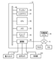
- the console 14 has a display 50, an input device 51, a CPU 52, a memory 53, a storage device 54, and a communication unit 55. These are interconnected via a data bus 56.
- the display 50 is a display unit that displays various operation screens, X-ray image XP, and optical images (still image SP and moving image MP) equipped with operation functions by GUI (Graphical User Interface).
- the input device 51 is an input operation unit including a touch panel, a keyboard, and the like.
- the storage device 54 is, for example, an HDD (Hard Disk Drive) array, which is built in the console 14 or externally connected to the console 14. External connections are connected through cables or networks.
- the storage device 54 stores control programs such as an operating system, various application programs, and various data associated with these programs.
- the memory 53 is a work memory for the CPU 52 to execute a process.
- the CPU 52 collectively controls each part of the console 14 by loading the program stored in the storage device 54 into the memory 53 and executing processing according to the program.
- the communication unit 55 transmits and receives various data such as an X-ray image XP and an optical image (still image SP and moving image MP) between the electronic cassette 13 and the optical camera 15. Further, the communication unit 55 communicates with the control unit 12C of the radiation source control device 12.
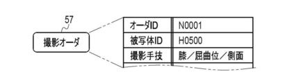
- the console 14 accepts the input of the shooting order 57 shown in FIG.
- the imaging order 57 is information for instructing the technician RG to perform X-ray imaging, for example, from a imaging requester in a clinical department.
- the shooting order 57 is delivered from the RIS to the console 14.
- the shooting order 57 has items such as an order ID (Identification Data), a subject ID, and a shooting technique.
- the order ID is a symbol or number that identifies each shooting order 57, and is automatically assigned by the RIS.
- the subject ID of the subject H to be photographed is recorded.
- the subject ID is a symbol or number that identifies each subject H.
- the shooting technique is information on the shooting part of the subject H and the posture and orientation of the shooting part.
- the imaging site includes the head, cervical spine, chest, abdomen, hands, fingers, elbows, and the like.
- the posture is the posture of the subject H such as a standing position, a lying position, or a sitting position.
- the orientation is the orientation of the subject H with respect to the X-ray source 11 such as the front surface, the side surface, or the back surface.
- the photographing order 57 includes items of subject information (patient information) such as the name, gender, age, height, and weight of the subject H.
- the condition table 58 shown in FIG. 7 is stored in the storage device 54 of the console 14. In the condition table 58, the irradiation conditions corresponding to each imaging technique are registered in association with each other.
- the console 14 displays the shooting order list, which lists the contents of the shooting order 57 shown in FIG. 6, on the display 50 by the operation of the engineer RG.
- the engineer RG can browse the shooting order list and confirm the contents of the shooting order 57. Further, the console 14 displays the contents of the condition table 58 shown in FIG. 7 on the display 50.
- the engineer RG can select and set irradiation conditions that match the imaging technique specified in the imaging order 57.
- the console 14 wirelessly transmits a condition setting signal including various information such as irradiation conditions set by the engineer RG, an order ID, and a console ID as console identification information to the electronic cassette 13.
- the console 14 stores the X-ray image XP received from the electronic cassette 13 in the storage device 54 as a storage unit, for example, as an image file in a format compliant with the DICOM (Digital Imaging and Communication in Medicine) standard.
- image file the X-ray image XP and the incidental information are associated with one image ID.
- Ancillary information includes order ID, subject ID, patient information, imaging technique, irradiation conditions, and the like.
- the still image SP obtained by the optical camera 15 taking a still image in conjunction with the irradiation start detection signal SI includes the image ID (X-ray image) of the X-ray image XP obtained by the X-ray photography.
- An image ID (optical image ID) associated with the ID) is attached.
- the X-ray image XP and the still image SP obtained during one X-ray imaging are stored in the storage device 54 in association with the X-ray image ID and the optical image ID.
- the doctor mainly diagnoses the joint cavity JC of the knee based on the X-ray image XP. Therefore, the joint cavity JC needs to be clearly depicted in the X-ray image XP.
- FIG. 9 shows various functions configured in the CPU 52.
- the operation program 60 is stored in the storage device 54.
- the condition table 58 shown in FIG. 7 is also stored in the storage device 54.
- a plurality of functional units are configured in the CPU 52 by executing the operation program 60.
- the operation program 60 causes the CPU 52 to function as a still image shooting instruction unit 61, a still image acquisition unit 62, an association unit 63, a moving image shooting instruction unit 64, a moving image acquisition unit 65, a superimposition processing unit 66, and a display control unit 67.
- the still image shooting instruction unit 61 transmits an irradiation start detection signal SI transmitted from the electronic cassette 13 in response to the fact that the irradiation switch 16 is pressed and the X-ray irradiation from the X-ray source 11 to the electronic cassette 13 is started. , Receives via the communication unit 55. The still image shooting instruction unit 61 instructs the optical camera 15 to perform still image shooting in response to receiving the irradiation start detection signal SI from the electronic cassette 13.
- the still image acquisition unit 62 acquires the still image SP generated by the optical camera 15 taking a still image.
- the still image SP acquired by the still image acquisition unit 62 is input to the association unit 63. Further, in the association unit 63, an X-ray image XP detected by the electronic cassette 13 based on the X-rays emitted from the X-ray source 11 in response to the pressing of the irradiation switch 16 is transmitted via the communication unit 55. Is entered.
- the association unit 63 associates the still image SP input to the still image acquisition unit 62 with the X-ray image XP input from the electronic cassette 13 and stores them in the storage device 54 as shown in FIG.
- the association unit 63 associates the associated still image SP and the X-ray image XP with incidental information (see FIG. 8) such as the above-mentioned patient information and stores the information in the storage device 54.
- the movie shooting instruction unit 64 transmits a movie shooting start signal instructing the optical camera 15 to start movie shooting in response to the re-shooting preparation start signal RS being input from the input device 51.
- the engineer RG confirms the X-ray image XP acquired by X-ray imaging, and if it determines that the image is not captured, operates the input device 51 to shift the imaging support device to the preparation mode for re-imaging. Let me. When the imaging technique is "knee / flexion / lateral", the technician RG determines that the image is lost when, for example, the joint cavity JC of the knee is not clearly depicted in the X-ray image XP.
- the moving image acquisition unit 65 acquires the moving image MP generated by the optical camera 15 taking a moving image in real time for each frame.
- the moving image acquisition unit 65 acquires an optical image for each frame and outputs a moving image MP composed of the acquired plurality of frames.
- the moving image MP output from the moving image acquisition unit 65 is input to the superimposition processing unit 66 for each frame.
- the superimposition processing unit 66 acquires the still image SP stored in the storage device 54, and superimposes the still image SP on each frame of the moving image MP as shown in FIG.
- the superimposition processing unit 66 inputs the superimposition image TP generated by superimposing the moving image MP and the still image SP to the display control unit 67 for each frame.
- the display control unit 67 displays the superimposed image TP on the display 50 frame by frame. That is, the display control unit 67 superimposes the still image SP on the moving image MP and displays it on the display 50 in real time.
- the still image SP in the superimposed image TP is associated with the X-ray image XP that the engineer RG has determined to be a photo loss, and indicates the position of the subject H at the time of the photo loss.
- the moving image MP in the superimposed image TP indicates the current position of the subject H during preparation for re-shooting. Therefore, the engineer RG can confirm the current position of the subject H with respect to the time of copying loss by confirming the superimposed image TP displayed in real time on the display 50.
- the moving image shooting of the optical camera 15 ends in response to the reception of the still image shooting execution instruction from the still image shooting instruction unit 61 described above. After the moving image shooting is completed, the moving image MP is discarded without being saved in the storage device 54. This is for the purpose of preventing the moving image MP from being saved in the storage device 54, that is, protecting privacy when unnecessary information is displayed on the moving image MP during the preparation for shooting.
- the still image acquisition unit 62 may acquire one frame of the moving image MP as the still image SP.
- the display control unit 67 displays a console screen on the display 50, which enables the engineer RG to perform various operations such as selection of the shooting order 57 using the input device 51. Further, the display control unit 67 displays the X-ray image XP or the superimposed image TP in the console screen.
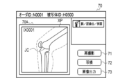
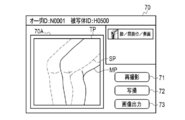
- FIG. 11 shows an example of a console screen displayed on the display 50 by the display control unit 67.
- the console screen 70 is provided with an image display area 70A for displaying an image such as an X-ray image XP or a superposed image TP.
- a first operation button 71 for performing re-shooting a first operation button 71 for performing re-shooting
- a second operation button 72 for outputting the X-ray image XP determined to be a copying loss to the copying loss management system 19, and an X-ray.
- a third operation button 73 for outputting the image XP to the PACS is displayed.
- the first operation button 71, the second operation button 72, and the third operation button 73 are operated by a touch panel formed on the screen of the display 50.
- FIG. 11 shows a display example of the console screen 70 after X-ray photography.
- the X-ray image XP obtained by X-ray photography is displayed in the image display area 70A.
- the engineer RG determines that the X-ray image XP is not an image suitable for diagnosis and re-imaging is necessary (that is, copying loss)
- the engineer RG presses the second operation button 72 to obtain the X-ray image.
- XP can be transmitted to the copying loss management system 19.
- the engineer RG can start the X-ray imaging system 10 to start the imaging preparation operation for reimaging by pressing the first operation button 71.
- the engineer RG determines that the X-ray image XP is an image suitable for diagnosis and re-imaging is unnecessary, the engineer RG presses the third operation button 73 to PACS the X-ray image XP. Can be sent to.
- the console 14 When the console 14 transmits the X-ray image XP to the outside such as the photo loss management system 19 or the PACS, the console 14 provides incidental information such as patient information to the still image SP and the X-ray image XP associated with the association unit 63. It is preferable to output a file (see FIG. 8) associated with.
- FIG. 12 shows a display example of the console screen 70 in the shooting preparation operation for reshooting.
- the superimposed image TP in which the still image SP is superimposed on the moving image MP is displayed in the image display area 70A.
- the still image SP indicates the position of the subject H at the time of shooting loss.
- the moving image MP indicates the current position of the subject H in the shooting preparation operation.
- the engineer RG can position the subject H while referring to the still image SP indicating the position of the subject H at the time of copying loss.
- the engineer RG confirms the contents of the photographing order 57 on the display 50 and sets the irradiation conditions using the input device 51 and the touch panel 12A prior to the photographing.
- the engineer RG positions the X-ray source 11, the electronic cassette 13, and the subject H according to the photographing technique included in the photographing order 57.
- the shooting technique is "knee / flexion / side”.
- the engineer RG bends one leg of the subject H and positions the subject H so that the side surface of the knee faces the X-ray incident surface 13A of the electronic cassette 13 and the knee is located at the center of the irradiation field RF ( (See FIG. 1).
- the still image shooting instruction unit 61 determines whether or not the irradiation start detection signal SI has been received from the electronic cassette 13 (step S10).
- the irradiation start detection unit 33 of the electronic cassette 13 responds to the start of irradiation of X-rays from the X-ray source 11 to the electronic cassette 13 by pressing the irradiation switch 16 by the engineer RG. This is a timing signal that detects the start of X-ray irradiation and is transmitted from the electronic cassette 13 to the console 14.
- the electronic cassette 13 detects the X-ray image XP of the subject H based on the X-rays transmitted through the subject H.
- the still image shooting instruction unit 61 When the still image shooting instruction unit 61 receives the irradiation start detection signal SI (step S10: YES), the still image shooting instruction unit 61 instructs the optical camera 15 to execute the still image shooting (step S11).
- the still image acquisition unit 62 acquires the still image SP generated by the optical camera 15 taking a still image (step S12). Further, the console 14 acquires the X-ray image XP detected by the electronic cassette 13 (step S13).
- the association unit 63 associates the acquired X-ray image XP with the still image SP and saves it in the storage device 54 (step S14).
- the display control unit 67 displays the X-ray image XP stored in the storage device 54 in the image display area 70A of the console screen 70 (step S15).
- the CPU 52 determines whether or not the engineer RG has been instructed to output an image by pressing the third operation button 73 (step S16).
- the engineer RG confirms the X-ray image XP (see FIG. 11) displayed in the image display area 70A, and when it is determined that re-shooting is unnecessary, the engineer RG instructs the image output by pressing the third operation button 73. I do.
- the CPU 52 determines that the third operation button 73 has been pressed (step S16: YES)
- the CPU 52 outputs the X-ray image XP stored in the storage device 54 to the PACS (step S25), and ends the process.
- the engineer RG confirms the X-ray image XP displayed in the image display area 70A, and when it is determined that re-imaging is necessary, the engineer RG presses the second operation button 72 to obtain the X-ray image XP. Is instructed to be transmitted to the copying loss management system 19. After that, the engineer RG instructs the start of preparation for re-shooting by pressing the first operation button 71. When the first operation button 71 is pressed, the input device 51 generates a re-shooting preparation start signal RS and transmits it to the moving image shooting instruction unit 64.
- step S16 determines whether or not the re-shooting preparation start signal RS has been received from the input device 51. Determine (step S17).
- step S17 receives the re-shooting preparation start signal RS
- step S18 transmits the moving image shooting start signal to the optical camera 15 (step S18).
- the moving image acquisition unit 65 acquires the moving image MP generated by the optical camera 15 taking a moving image for each frame (step S19).
- the superimposition processing unit 66 acquires the still image SP stored in the storage device 54, and superimposes the still image SP on the frame of the moving image MP acquired by the moving image acquisition unit 65 to superimpose the superimposed image.
- Generate TP step S20.
- the display control unit 67 displays the superposed image TP generated by the superimposing processing unit 66 in the image display area 70A of the console screen 70 (step S23).
- the engineer RG positions the subject H while referring to the still image SP indicating the position of the subject H at the time of image loss. Can be done.
- the engineer RG gives an instruction to execute X-ray photography by pressing the irradiation switch 16.
- the still image shooting instruction unit 61 determines whether or not the irradiation start detection signal SI has been received from the electronic cassette 13 (step S24). While the still image shooting instruction unit 61 does not receive the irradiation start detection signal SI (step S24: NO), the process is returned to step S19, and the moving image acquisition unit 65 acquires the next frame of the moving image MP. Until the irradiation start detection signal SI is received, the processes of steps S19 to S24 are repeatedly executed. As a result, the superimposed image TP in which the still image SP is superimposed on the moving image MP is displayed in real time in the image display area 70A.
- step S24 YES
- the still image shooting instruction unit 61 executes still image shooting with respect to the optical camera 15.
- Step S11 When the optical camera 15 receives an instruction to execute the still image shooting, the optical camera 15 ends the moving image shooting and performs the still image shooting. After that, the same process is executed.
- the irradiation switch 16 After the irradiation switch 16 is pressed by the engineer RG, it takes a certain amount of time for the radiation source control device 12 to generate X-rays in the X-ray tube 11A. Therefore, after the irradiation switch 16 is pressed, X-rays are emitted. There is a time lag before the start of irradiation. In particular, when the irradiation switch 16 is a two-step switch capable of performing a two-step pressing operation of half-pressing and full-pressing, the time lag becomes large.
- the irradiation switch 16 is a two-stage switch, for example, the warm-up of the X-ray tube 11A is started in response to the half-pressing of the irradiation switch 16, and after the warm-up is completed, the irradiation switch 16 is set. When fully pressed, the X-ray tube 11A generates X-rays. Since it takes a certain amount of time to warm up the X-ray tube 11A, the time lag becomes large.
- the still image shooting by the optical camera 15 is executed at the timing when the irradiation switch 16 is pressed, the still image shooting is performed before the actual X-ray shooting is performed. Therefore, the acquisition times of the X-ray image XP associated with the association unit 63 and stored in the storage device 54 and the still image SP are different from each other. If the acquisition time of the X-ray image XP and the still image SP is different, the still image SP in the superimposed image TP is not an image that accurately represents the position of the subject H at the time of loss of image, and therefore the subject at the time of re-shooting. The positioning accuracy of H is lowered, and there is a possibility that image loss may occur again.
- the CPU 52 executes still image shooting by the optical camera 15 at the timing when the irradiation start detection signal SI is received from the electronic cassette 13 instead of the timing when the irradiation switch 16 is pressed. I'm letting you.
- the deviation of the acquisition time between the X-ray image XP and the still image SP associated by the association unit 63 is reduced, and the positioning accuracy of the subject H at the time of re-shooting is improved.
- the possibility of re-imaging due to re-imaging is reduced, and the amount of exposure of the subject H to X-rays can be suppressed.
- the engineer RG determines the necessity of re-shooting using only the X-ray image XP
- the X-ray image XP that does not need to be re-photographed is mistakenly determined to be a copying loss, so that unnecessary re-shooting is performed. There is a possibility of doing. Further, depending on the physical characteristics of the subject H and the like, there may be no possibility of improvement even after re-shooting. In such a case, unnecessary re-shooting may be repeated.
- the shooting support device having the above configuration the X-ray image XP and the still image SP with little deviation in the acquisition time are acquired. Therefore, by using the still image SP captured at the same time as the X-ray image XP for the determination of re-imaging, the necessity of re-imaging can be determined more accurately.
- the effect of the imaging support device having the above configuration regarding the positioning of the subject H will be described with reference to FIGS. 14 and 15.
- the joint cavity JC needs to be clearly depicted in the X-ray image XP, but since X-rays are a bundle of lines radiating from the focal point of the X-ray source 11. , The incident angle of X-rays changes due to a slight misalignment of the joint, and the depiction of the joint cavity JC becomes unclear. If the depiction of the joint cavity JC is unclear, the image will be lost and re-imaging will be required.
- the engineer RG can accurately grasp the position of the subject H at the time of shooting loss. Cannot make fine adjustments. If the engineer RG repositions the subject H from the beginning, there is a high possibility that the subject H will be positioned at the same position again, and the image loss will occur again. Further, even if the subject H is positioned by using an optical camera or the like before the X-ray photography, if the shooting loss occurs, the engineer RG cannot grasp the position of the subject H at the time of the shooting loss. , There is a high possibility that shooting loss will occur again, and re-shooting will be repeated.
- an optical image (still image SP) showing the subject H is acquired together with the X-ray image XP in conjunction with the start of X-ray irradiation.
- the engineer RG can easily grasp the position of the subject H at the time of the image loss. Therefore, the engineer RG can position the subject H at the position at the time of shooting loss and then finely adjust the position of the subject H from the position at the time of shooting loss based on the reason for the shooting loss or the like.
- a good X-ray image XP can be obtained by finely adjusting the position of the subject H and then performing re-imaging.
- the superimposed image TP in which the optical image (still image SP) acquired in conjunction with the start of X-ray irradiation and the current optical image (moving image MP) of the subject H are superimposed is displayed in real time. do. Even if the subject H moves significantly from the time of shooting loss, the engineer RG can more easily grasp the position of the subject H at the time of shooting loss based on the still image SP in the superimposed image TP.
- the still image acquisition unit 62 acquires the still image SP obtained by the optical camera 15 receiving an instruction from the still image shooting instruction unit 61 and performing the still image shooting.
- the still image acquisition unit 62 extracts one frame from the moving image MP based on the irradiation start detection signal SI transmitted from the electronic cassette 13, and extracts the extracted frame into the still image SP. Get as.
- the still image acquisition unit 62 receives the irradiation start detection signal SI from the electronic cassette 13 from the plurality of frames F constituting the moving image MP acquired by the moving image acquisition unit 65.
- the frame F corresponding to the time is extracted.
- the still image acquisition unit 62 sets the extracted frame F as the still image SP, and discards the remaining frames F other than the extracted frame F.
- the still image acquisition unit 62 may store the time when the irradiation start detection signal SI is received from the electronic cassette 13 and extract the frame F from the moving image MP after the end of the X-ray photography.
- the moving image MP acquired by the moving image acquisition unit 65 is stored in the storage device 54 or the like, the frame F corresponding to the reception time of the irradiation start detection signal SI is extracted as the still image SP, and then the moving image MP is stored. Erase from the device 54 or the like.
- the still image SP acquired by the still image acquisition unit 62 is associated with the X-ray image XP by the association unit 63 and stored in the storage device 54, as in the first embodiment.
- the asynchronous electronic cassette 13 is used as the radiographic image detector, but in the second embodiment, the synchronous electronic cassette 13B is used as the radiographic image detector.
- the electronic cassette 13B starts operation in response to receiving a control signal from the console 14. Therefore, the electronic cassette 13B does not include the irradiation start detection unit 33.
- the console 14 transmits a preparation request signal EQU requesting preparation for X-ray detection to the electronic cassette 13B before starting irradiation of X-rays from the X-ray source 11.
- the electronic cassette 13B Upon receiving the preparation request signal EQU, the electronic cassette 13B performs the above-mentioned reset operation and the like, and then transmits a preparation completion signal RDY indicating that the X-ray detection preparation is completed to the console 14.
- the console 14 causes the optical camera 15 to take a still image in conjunction with the ready signal RDY transmitted from the electronic cassette 13.
- the preparation completion signal RDY is an example of a timing signal according to the technique of the present disclosure.
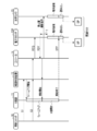
- FIG. 17 is a sequence diagram showing the operation timing of each part of the X-ray imaging system according to the second embodiment.
- the irradiation switch 16 is the above-mentioned two-stage switch.
- the irradiation switch 16 transmits the first operation signal S1 to the radiation source control device 12.
- the radiation source control device 12 Upon receiving the first operation signal S1, the radiation source control device 12 causes the X-ray source 11 to start warming up the X-ray tube 11A.
- the second operation signal S2 is transmitted from the irradiation switch 16 to the radiation source control device 12.
- the console 14 transmits a preparation request signal EQU to the electronic cassette 13B.
- the electronic cassette 13B transmits a preparation completion signal RDY to the console 14 after performing a reset operation or the like.
- the console 14 Upon receiving the ready signal RDY, the console 14 causes the X-ray source 11 to start irradiating X-rays.
- the console 14 receives the preparation completion signal RDY, the still image shooting instruction unit 61 instructs the optical camera 15 to execute the still image shooting.
- the electronic cassette 13B starts charge accumulation for X-ray photography after the lapse of the predetermined time T after transmitting the preparation request signal EQU to the console 14.
- the default time T is a value of 0 or more.
- the optical camera 15 After receiving the execution instruction of the still image shooting, the optical camera 15 starts the charge accumulation for the still image shooting.
- the console 14 transmits the irradiation end signal STP to the electronic cassette 13B after the predetermined X-ray irradiation time has elapsed.
- the electronic cassette 13B Upon receiving the irradiation end signal STP, the electronic cassette 13B performs a read-out operation to generate an X-ray image XP.
- the optical camera 15 generates a still image SP by performing a read operation after the elapse of a predetermined exposure time after starting charge accumulation.
- the console 14 causes the optical camera 15 to take a still image based on the irradiation start detection signal SI transmitted from the electronic cassette 13.
- the console 14 causes the optical camera 15 to take a still image based on a signal transmitted from an automatic exposure controller provided separately from the electronic cassette 13.
- FIG. 18 shows the configuration of the X-ray imaging system according to the third embodiment.
- an AEC (Automatic Exposure Control) sensor 80 as an automatic exposure controller is provided in the vicinity of the electronic cassette 13.
- the electronic cassette 13 is held on the photographing table 81.
- the shooting table 81 is a shooting table such as a standing shooting table or a lying shooting table.
- the AEC sensor 80 is held on the photographing table 81 and is arranged on the front side or the back side of the electronic cassette 13.
- the AEC sensor 80 is a sensor that measures the dose of X-rays that have passed through the subject H, and transmits the dose detection signal Sd to the console 14.
- the console 14 supplies the detection signal Sd to the control unit 12C of the radiation source control device 12.
- the control unit 12C stops the X-ray irradiation by the X-ray source 11 when the cumulative dose reaches the target dose based on the dose detection signal Sd.
- the X-ray irradiation is stopped even before the irradiation time included in the preset X-ray irradiation conditions is reached.
- the dose detection signal Sd transmitted from the AEC sensor 80 to the console 14 is also supplied to the still image shooting instruction unit 61.
- the still image shooting instruction unit 61 instructs the optical camera 15 to execute still image shooting in response to receiving the detection signal Sd.
- the detection signal Sd is an example of a radiation detection signal output from the automatic exposure controller.
- Each of the X-ray imaging systems according to the above embodiments is characterized in that the optical image acquired by the optical camera is associated with the radiation image based on the timing signal transmitted from the radiation image detector side.
- the optical image acquired by the optical camera is associated with the radiation image based on the timing signal transmitted from the radiation image detector side.
- the technique of the present disclosure can be applied not only to X-rays but also to a system for photographing a subject using other radiation such as ⁇ -rays.
- various processes such as a still image shooting instruction unit 61, a still image acquisition unit 62, an association unit 63, a moving image shooting instruction unit 64, a moving image acquisition unit 65, a superimposition processing unit 66, and a display control unit 67.
- the hardware structure of the processing unit that executes the above is various processors as shown below.
- processors include a CPU, a programmable logic device (PLD), a dedicated electric circuit, and the like.
- a CPU is a general-purpose processor that executes software (program) and functions as various processing units.
- PLD is a processor such as FPGA (Field Programmable Gate Array) whose circuit configuration can be changed after manufacturing.
- a dedicated electric circuit is a processor having a circuit configuration designed exclusively for executing a specific process such as an ASIC (Application Specific Integrated Circuit).
- One processing unit may be composed of one of these various processors, or may be composed of a combination of two or more processors of the same type or different types (for example, a plurality of FPGAs or a combination of a CPU and an FPGA). May be done. Further, a plurality of processing units may be configured by one processor. As an example of configuring a plurality of processing units with one processor, first, there is a form in which one processor is configured by a combination of one or more CPUs and software, and this processor functions as a plurality of processing units. ..
- SoC System On Chip
- the various processing units are configured by using one or more of the above-mentioned various processors as a hardware-like structure.
- the present invention is not limited to each of the above embodiments, and various configurations can be adopted as long as the gist of the present invention is not deviated. Further, in addition to the program, the present invention extends to a computer-readable storage medium that stores the program non-temporarily.
Landscapes
- Health & Medical Sciences (AREA)
- Life Sciences & Earth Sciences (AREA)
- Medical Informatics (AREA)
- Engineering & Computer Science (AREA)
- Physics & Mathematics (AREA)
- Public Health (AREA)
- Veterinary Medicine (AREA)
- General Health & Medical Sciences (AREA)
- Pathology (AREA)
- Biophysics (AREA)
- Biomedical Technology (AREA)
- Heart & Thoracic Surgery (AREA)
- Molecular Biology (AREA)
- Surgery (AREA)
- Animal Behavior & Ethology (AREA)
- Nuclear Medicine, Radiotherapy & Molecular Imaging (AREA)
- Radiology & Medical Imaging (AREA)
- Optics & Photonics (AREA)
- High Energy & Nuclear Physics (AREA)
- Mathematical Physics (AREA)
- Apparatus For Radiation Diagnosis (AREA)
Priority Applications (4)
| Application Number | Priority Date | Filing Date | Title |
|---|---|---|---|
| JP2022511762A JP7453345B2 (ja) | 2020-03-30 | 2021-03-11 | 撮影支援装置、その作動方法、及び作動プログラム |
| CN202180025105.0A CN115348836B (zh) | 2020-03-30 | 2021-03-11 | 摄影辅助装置、其工作方法及存储介质 |
| EP21779977.4A EP4129184B1 (en) | 2020-03-30 | 2021-03-11 | Imaging assistance device, method for operating same, and operation program |
| US17/950,107 US12239415B2 (en) | 2020-03-30 | 2022-09-22 | Imaging support device, operation method for the same, and operation program |
Applications Claiming Priority (2)
| Application Number | Priority Date | Filing Date | Title |
|---|---|---|---|
| JP2020061592 | 2020-03-30 | ||
| JP2020-061592 | 2020-03-30 |
Related Child Applications (1)
| Application Number | Title | Priority Date | Filing Date |
|---|---|---|---|
| US17/950,107 Continuation US12239415B2 (en) | 2020-03-30 | 2022-09-22 | Imaging support device, operation method for the same, and operation program |
Publications (1)
| Publication Number | Publication Date |
|---|---|
| WO2021200023A1 true WO2021200023A1 (ja) | 2021-10-07 |
Family
ID=77930202
Family Applications (1)
| Application Number | Title | Priority Date | Filing Date |
|---|---|---|---|
| PCT/JP2021/009922 Ceased WO2021200023A1 (ja) | 2020-03-30 | 2021-03-11 | 撮影支援装置、その作動方法、及び作動プログラム |
Country Status (5)
| Country | Link |
|---|---|
| US (1) | US12239415B2 (https=) |
| EP (1) | EP4129184B1 (https=) |
| JP (1) | JP7453345B2 (https=) |
| CN (1) | CN115348836B (https=) |
| WO (1) | WO2021200023A1 (https=) |
Citations (7)
| Publication number | Priority date | Publication date | Assignee | Title |
|---|---|---|---|---|
| JPH06217973A (ja) | 1993-01-27 | 1994-08-09 | Toshiba Corp | X線撮影装置 |
| JP2008206740A (ja) | 2007-02-27 | 2008-09-11 | Fujifilm Corp | 放射線撮像システム、放射線撮像方法およびプログラム |
| JP2011139761A (ja) * | 2010-01-06 | 2011-07-21 | Toshiba Corp | X線診断装置及びx線診断装置の制御方法 |
| JP2012029916A (ja) * | 2010-07-30 | 2012-02-16 | Fujifilm Corp | 放射線画像撮影システム及び放射線画像撮影方法 |
| JP2014117368A (ja) * | 2012-12-14 | 2014-06-30 | Toshiba Corp | X線診断装置及びその制御方法 |
| JP2019033830A (ja) * | 2017-08-10 | 2019-03-07 | 富士フイルム株式会社 | 放射線撮影システムとその作動方法 |
| JP2019097769A (ja) * | 2017-11-30 | 2019-06-24 | キヤノンメディカルシステムズ株式会社 | X線診断装置、位置合わせ情報作成装置、およびx線診断システム |
Family Cites Families (12)
| Publication number | Priority date | Publication date | Assignee | Title |
|---|---|---|---|---|
| JP2004121369A (ja) * | 2002-09-30 | 2004-04-22 | Fuji Photo Film Co Ltd | 放射線画像記録装置 |
| JP2011024721A (ja) * | 2009-07-23 | 2011-02-10 | Hitachi Medical Corp | X線診断装置 |
| CN102958436A (zh) | 2010-07-30 | 2013-03-06 | 富士胶片株式会社 | 放射线图像成像系统、放射线图像成像方法、以及图像显示方法 |
| CN103239253B (zh) * | 2012-02-14 | 2015-07-15 | 株式会社东芝 | 医用图像诊断装置 |
| JP5945513B2 (ja) * | 2013-02-20 | 2016-07-05 | 富士フイルム株式会社 | 放射線画像処理装置および方法、並びに放射線撮影装置 |
| JP6122410B2 (ja) * | 2014-09-22 | 2017-04-26 | 富士フイルム株式会社 | 携帯型コンソール、携帯型コンソールの制御方法、携帯型コンソール用プログラム、及び放射線撮影システム |
| US10806518B2 (en) * | 2016-04-27 | 2020-10-20 | Arthrology Consulting, Llc | Methods for augmenting a surgical field with virtual guidance and tracking and adapting to deviation from a surgical plan |
| US20180125605A1 (en) * | 2016-11-10 | 2018-05-10 | SK Commercial Construction, Inc. | Method and system for correlating anatomy using an electronic mobile device transparent display screen |
| JP6882114B2 (ja) * | 2017-08-10 | 2021-06-02 | 富士フイルム株式会社 | 放射線撮影システムとその作動方法 |
| US10568602B2 (en) * | 2017-09-06 | 2020-02-25 | General Electric Company | Virtual positioning image for use in imaging |
| JP2019166275A (ja) * | 2018-03-26 | 2019-10-03 | キヤノン株式会社 | 情報処理装置、情報処理方法及びプログラム |
| JP7073961B2 (ja) * | 2018-07-24 | 2022-05-24 | コニカミノルタ株式会社 | 動態画像解析装置、動態画像解析方法及びプログラム |
-
2021
- 2021-03-11 JP JP2022511762A patent/JP7453345B2/ja active Active
- 2021-03-11 WO PCT/JP2021/009922 patent/WO2021200023A1/ja not_active Ceased
- 2021-03-11 EP EP21779977.4A patent/EP4129184B1/en active Active
- 2021-03-11 CN CN202180025105.0A patent/CN115348836B/zh active Active
-
2022
- 2022-09-22 US US17/950,107 patent/US12239415B2/en active Active
Patent Citations (7)
| Publication number | Priority date | Publication date | Assignee | Title |
|---|---|---|---|---|
| JPH06217973A (ja) | 1993-01-27 | 1994-08-09 | Toshiba Corp | X線撮影装置 |
| JP2008206740A (ja) | 2007-02-27 | 2008-09-11 | Fujifilm Corp | 放射線撮像システム、放射線撮像方法およびプログラム |
| JP2011139761A (ja) * | 2010-01-06 | 2011-07-21 | Toshiba Corp | X線診断装置及びx線診断装置の制御方法 |
| JP2012029916A (ja) * | 2010-07-30 | 2012-02-16 | Fujifilm Corp | 放射線画像撮影システム及び放射線画像撮影方法 |
| JP2014117368A (ja) * | 2012-12-14 | 2014-06-30 | Toshiba Corp | X線診断装置及びその制御方法 |
| JP2019033830A (ja) * | 2017-08-10 | 2019-03-07 | 富士フイルム株式会社 | 放射線撮影システムとその作動方法 |
| JP2019097769A (ja) * | 2017-11-30 | 2019-06-24 | キヤノンメディカルシステムズ株式会社 | X線診断装置、位置合わせ情報作成装置、およびx線診断システム |
Also Published As
| Publication number | Publication date |
|---|---|
| JP7453345B2 (ja) | 2024-03-19 |
| CN115348836A (zh) | 2022-11-15 |
| EP4129184A1 (en) | 2023-02-08 |
| US12239415B2 (en) | 2025-03-04 |
| EP4129184B1 (en) | 2025-09-24 |
| CN115348836B (zh) | 2025-11-11 |
| US20230015698A1 (en) | 2023-01-19 |
| JPWO2021200023A1 (https=) | 2021-10-07 |
| EP4129184A4 (en) | 2023-09-27 |
Similar Documents
| Publication | Publication Date | Title |
|---|---|---|
| JP5859934B2 (ja) | 放射線撮影システム並びにその作動方法、および放射線画像検出装置並びにその作動プログラム | |
| CN105073007B (zh) | 放射线图像处理装置和方法以及放射线摄影装置 | |
| JP5460674B2 (ja) | 放射線撮影装置およびその制御方法、並びに放射線撮影システム | |
| JP5602198B2 (ja) | 放射線撮影装置、およびこれに用いられる放射線画像検出装置並びにその作動方法 | |
| JP5675682B2 (ja) | 放射線画像検出装置及びその制御方法、並びに放射線撮影システム | |
| JP7282914B2 (ja) | 撮影支援装置、その作動方法および作動プログラム | |
| CN109381206B (zh) | 图像处理装置及其工作方法 | |
| JP2013162963A (ja) | 放射線画像検出装置および放射線撮影システム | |
| JP3832173B2 (ja) | 医用画像読取装置 | |
| US12133753B2 (en) | Imaging support device, operation method for the same and operation program | |
| WO2021200001A1 (ja) | 撮影支援装置、その作動方法、及び作動プログラム | |
| JP5984294B2 (ja) | 放射線撮影システム、放射線発生装置およびその作動方法 | |
| JP2000350718A (ja) | X線撮影装置、方法及びコンピュータ読み取り可能な記憶媒体 | |
| JP7453345B2 (ja) | 撮影支援装置、その作動方法、及び作動プログラム | |
| JP7348361B2 (ja) | 画像処理装置 | |
| JP2025089033A (ja) | 動態画像撮影システム、撮影制御方法及びプログラム | |
| JP2024077027A (ja) | 放射線撮影システム | |
| JP2016000296A (ja) | 補正用画像作成装置、放射線画像撮影装置、撮影装置、プログラム、および補正用画像作成方法 |
Legal Events
| Date | Code | Title | Description |
|---|---|---|---|
| 121 | Ep: the epo has been informed by wipo that ep was designated in this application |
Ref document number: 21779977 Country of ref document: EP Kind code of ref document: A1 |
|
| ENP | Entry into the national phase |
Ref document number: 2022511762 Country of ref document: JP Kind code of ref document: A |
|
| NENP | Non-entry into the national phase |
Ref country code: DE |
|
| ENP | Entry into the national phase |
Ref document number: 2021779977 Country of ref document: EP Effective date: 20221031 |
|
| WWG | Wipo information: grant in national office |
Ref document number: 2021779977 Country of ref document: EP |