WO2021200023A1 - 撮影支援装置、その作動方法、及び作動プログラム - Google Patents
撮影支援装置、その作動方法、及び作動プログラム Download PDFInfo
- Publication number
- WO2021200023A1 WO2021200023A1 PCT/JP2021/009922 JP2021009922W WO2021200023A1 WO 2021200023 A1 WO2021200023 A1 WO 2021200023A1 JP 2021009922 W JP2021009922 W JP 2021009922W WO 2021200023 A1 WO2021200023 A1 WO 2021200023A1
- Authority
- WO
- WIPO (PCT)
- Prior art keywords
- image
- radiation
- subject
- ray
- shooting
- Prior art date
Links
- 238000003384 imaging method Methods 0.000 title claims abstract description 86
- 238000000034 method Methods 0.000 title claims description 32
- 230000003287 optical effect Effects 0.000 claims abstract description 116
- 230000005855 radiation Effects 0.000 claims abstract description 97
- 238000001514 detection method Methods 0.000 claims description 70
- 239000000284 extract Substances 0.000 claims description 4
- 230000002285 radioactive effect Effects 0.000 claims description 4
- 238000002601 radiography Methods 0.000 abstract description 7
- 238000002360 preparation method Methods 0.000 description 26
- 238000003860 storage Methods 0.000 description 24
- 230000004044 response Effects 0.000 description 14
- 238000004891 communication Methods 0.000 description 12
- 238000003825 pressing Methods 0.000 description 12
- 230000006870 function Effects 0.000 description 11
- 230000007246 mechanism Effects 0.000 description 10
- 210000003127 knee Anatomy 0.000 description 9
- 238000006243 chemical reaction Methods 0.000 description 8
- 230000008569 process Effects 0.000 description 8
- 239000000758 substrate Substances 0.000 description 8
- 239000000725 suspension Substances 0.000 description 6
- 238000009825 accumulation Methods 0.000 description 5
- 239000004065 semiconductor Substances 0.000 description 5
- 238000010586 diagram Methods 0.000 description 4
- 239000010408 film Substances 0.000 description 4
- 210000000629 knee joint Anatomy 0.000 description 4
- 230000002596 correlated effect Effects 0.000 description 3
- 230000000875 corresponding effect Effects 0.000 description 3
- 230000000694 effects Effects 0.000 description 3
- 230000004048 modification Effects 0.000 description 3
- 238000012986 modification Methods 0.000 description 3
- 230000002093 peripheral effect Effects 0.000 description 3
- 238000005070 sampling Methods 0.000 description 3
- 230000001360 synchronised effect Effects 0.000 description 3
- 238000003745 diagnosis Methods 0.000 description 2
- 238000007689 inspection Methods 0.000 description 2
- -1 thallium-activated cesium iodide Chemical class 0.000 description 2
- OAICVXFJPJFONN-UHFFFAOYSA-N Phosphorus Chemical compound [P] OAICVXFJPJFONN-UHFFFAOYSA-N 0.000 description 1
- BUGBHKTXTAQXES-UHFFFAOYSA-N Selenium Chemical compound [Se] BUGBHKTXTAQXES-UHFFFAOYSA-N 0.000 description 1
- 229910052771 Terbium Inorganic materials 0.000 description 1
- 210000001015 abdomen Anatomy 0.000 description 1
- 210000000988 bone and bone Anatomy 0.000 description 1
- 230000008859 change Effects 0.000 description 1
- 230000000295 complement effect Effects 0.000 description 1
- 230000001276 controlling effect Effects 0.000 description 1
- 230000001186 cumulative effect Effects 0.000 description 1
- 229940079593 drug Drugs 0.000 description 1
- 239000003814 drug Substances 0.000 description 1
- 238000005516 engineering process Methods 0.000 description 1
- 230000006872 improvement Effects 0.000 description 1
- 230000001678 irradiating effect Effects 0.000 description 1
- 210000002414 leg Anatomy 0.000 description 1
- 238000004519 manufacturing process Methods 0.000 description 1
- 239000011159 matrix material Substances 0.000 description 1
- 229910044991 metal oxide Inorganic materials 0.000 description 1
- 150000004706 metal oxides Chemical class 0.000 description 1
- 230000008520 organization Effects 0.000 description 1
- 229910052711 selenium Inorganic materials 0.000 description 1
- 239000011669 selenium Substances 0.000 description 1
- 230000002123 temporal effect Effects 0.000 description 1
- 229910052716 thallium Inorganic materials 0.000 description 1
- 239000010409 thin film Substances 0.000 description 1
- 238000010792 warming Methods 0.000 description 1
Images


Classifications
-
- A—HUMAN NECESSITIES
- A61—MEDICAL OR VETERINARY SCIENCE; HYGIENE
- A61B—DIAGNOSIS; SURGERY; IDENTIFICATION
- A61B5/00—Measuring for diagnostic purposes; Identification of persons
- A61B5/0059—Measuring for diagnostic purposes; Identification of persons using light, e.g. diagnosis by transillumination, diascopy, fluorescence
- A61B5/0077—Devices for viewing the surface of the body, e.g. camera, magnifying lens
-
- A—HUMAN NECESSITIES
- A61—MEDICAL OR VETERINARY SCIENCE; HYGIENE
- A61B—DIAGNOSIS; SURGERY; IDENTIFICATION
- A61B5/00—Measuring for diagnostic purposes; Identification of persons
- A61B5/0033—Features or image-related aspects of imaging apparatus classified in A61B5/00, e.g. for MRI, optical tomography or impedance tomography apparatus; arrangements of imaging apparatus in a room
- A61B5/0035—Features or image-related aspects of imaging apparatus classified in A61B5/00, e.g. for MRI, optical tomography or impedance tomography apparatus; arrangements of imaging apparatus in a room adapted for acquisition of images from more than one imaging mode, e.g. combining MRI and optical tomography
-
- A—HUMAN NECESSITIES
- A61—MEDICAL OR VETERINARY SCIENCE; HYGIENE
- A61B—DIAGNOSIS; SURGERY; IDENTIFICATION
- A61B5/00—Measuring for diagnostic purposes; Identification of persons
- A61B5/74—Details of notification to user or communication with user or patient ; user input means
- A61B5/742—Details of notification to user or communication with user or patient ; user input means using visual displays
- A61B5/7425—Displaying combinations of multiple images regardless of image source, e.g. displaying a reference anatomical image with a live image
-
- A—HUMAN NECESSITIES
- A61—MEDICAL OR VETERINARY SCIENCE; HYGIENE
- A61B—DIAGNOSIS; SURGERY; IDENTIFICATION
- A61B5/00—Measuring for diagnostic purposes; Identification of persons
- A61B5/74—Details of notification to user or communication with user or patient ; user input means
- A61B5/742—Details of notification to user or communication with user or patient ; user input means using visual displays
- A61B5/743—Displaying an image simultaneously with additional graphical information, e.g. symbols, charts, function plots
-
- A—HUMAN NECESSITIES
- A61—MEDICAL OR VETERINARY SCIENCE; HYGIENE
- A61B—DIAGNOSIS; SURGERY; IDENTIFICATION
- A61B6/00—Apparatus or devices for radiation diagnosis; Apparatus or devices for radiation diagnosis combined with radiation therapy equipment
- A61B6/08—Auxiliary means for directing the radiation beam to a particular spot, e.g. using light beams
-
- A—HUMAN NECESSITIES
- A61—MEDICAL OR VETERINARY SCIENCE; HYGIENE
- A61B—DIAGNOSIS; SURGERY; IDENTIFICATION
- A61B6/00—Apparatus or devices for radiation diagnosis; Apparatus or devices for radiation diagnosis combined with radiation therapy equipment
- A61B6/42—Arrangements for detecting radiation specially adapted for radiation diagnosis
- A61B6/4208—Arrangements for detecting radiation specially adapted for radiation diagnosis characterised by using a particular type of detector
- A61B6/4233—Arrangements for detecting radiation specially adapted for radiation diagnosis characterised by using a particular type of detector using matrix detectors
-
- A—HUMAN NECESSITIES
- A61—MEDICAL OR VETERINARY SCIENCE; HYGIENE
- A61B—DIAGNOSIS; SURGERY; IDENTIFICATION
- A61B6/00—Apparatus or devices for radiation diagnosis; Apparatus or devices for radiation diagnosis combined with radiation therapy equipment
- A61B6/44—Constructional features of apparatus for radiation diagnosis
- A61B6/4405—Constructional features of apparatus for radiation diagnosis the apparatus being movable or portable, e.g. handheld or mounted on a trolley
-
- A—HUMAN NECESSITIES
- A61—MEDICAL OR VETERINARY SCIENCE; HYGIENE
- A61B—DIAGNOSIS; SURGERY; IDENTIFICATION
- A61B6/00—Apparatus or devices for radiation diagnosis; Apparatus or devices for radiation diagnosis combined with radiation therapy equipment
- A61B6/44—Constructional features of apparatus for radiation diagnosis
- A61B6/4417—Constructional features of apparatus for radiation diagnosis related to combined acquisition of different diagnostic modalities
-
- A—HUMAN NECESSITIES
- A61—MEDICAL OR VETERINARY SCIENCE; HYGIENE
- A61B—DIAGNOSIS; SURGERY; IDENTIFICATION
- A61B6/00—Apparatus or devices for radiation diagnosis; Apparatus or devices for radiation diagnosis combined with radiation therapy equipment
- A61B6/44—Constructional features of apparatus for radiation diagnosis
- A61B6/4429—Constructional features of apparatus for radiation diagnosis related to the mounting of source units and detector units
- A61B6/4464—Constructional features of apparatus for radiation diagnosis related to the mounting of source units and detector units the source unit or the detector unit being mounted to ceiling
-
- A—HUMAN NECESSITIES
- A61—MEDICAL OR VETERINARY SCIENCE; HYGIENE
- A61B—DIAGNOSIS; SURGERY; IDENTIFICATION
- A61B6/00—Apparatus or devices for radiation diagnosis; Apparatus or devices for radiation diagnosis combined with radiation therapy equipment
- A61B6/54—Control of apparatus or devices for radiation diagnosis
- A61B6/542—Control of apparatus or devices for radiation diagnosis involving control of exposure
-
- A—HUMAN NECESSITIES
- A61—MEDICAL OR VETERINARY SCIENCE; HYGIENE
- A61B—DIAGNOSIS; SURGERY; IDENTIFICATION
- A61B6/00—Apparatus or devices for radiation diagnosis; Apparatus or devices for radiation diagnosis combined with radiation therapy equipment
- A61B6/58—Testing, adjusting or calibrating thereof
- A61B6/587—Alignment of source unit to detector unit
-
- A—HUMAN NECESSITIES
- A61—MEDICAL OR VETERINARY SCIENCE; HYGIENE
- A61B—DIAGNOSIS; SURGERY; IDENTIFICATION
- A61B6/00—Apparatus or devices for radiation diagnosis; Apparatus or devices for radiation diagnosis combined with radiation therapy equipment
- A61B6/58—Testing, adjusting or calibrating thereof
- A61B6/588—Setting distance between source unit and detector unit
-
- A—HUMAN NECESSITIES
- A61—MEDICAL OR VETERINARY SCIENCE; HYGIENE
- A61B—DIAGNOSIS; SURGERY; IDENTIFICATION
- A61B6/00—Apparatus or devices for radiation diagnosis; Apparatus or devices for radiation diagnosis combined with radiation therapy equipment
- A61B6/58—Testing, adjusting or calibrating thereof
- A61B6/589—Setting distance between source unit and patient
-
- A—HUMAN NECESSITIES
- A61—MEDICAL OR VETERINARY SCIENCE; HYGIENE
- A61B—DIAGNOSIS; SURGERY; IDENTIFICATION
- A61B2505/00—Evaluating, monitoring or diagnosing in the context of a particular type of medical care
- A61B2505/09—Rehabilitation or training
-
- A—HUMAN NECESSITIES
- A61—MEDICAL OR VETERINARY SCIENCE; HYGIENE
- A61B—DIAGNOSIS; SURGERY; IDENTIFICATION
- A61B6/00—Apparatus or devices for radiation diagnosis; Apparatus or devices for radiation diagnosis combined with radiation therapy equipment
- A61B6/04—Positioning of patients; Tiltable beds or the like
Definitions
- the technology of the present disclosure relates to a shooting support device, an operation method thereof, and an operation program.
- a radiological technologist or a doctor positions the imaging site of the subject, and then radiological imaging is performed based on the instructions of the technologist or the like. ..
- the moving subject may cause the imaging region to shift in position, and an image of the desired imaging region may not be obtained.
- imaging the failure to obtain a desired radiographic image by radiography, that is, the failure of radiography, is referred to as "imaging.” If there is a photo loss, re-shooting will be performed.
- an engineer or the like may mistakenly determine that a radiographic image that does not require re-imaging is a copying loss, so that unnecessary re-imaging may be performed. Re-shooting takes time and effort, and the amount of exposure to the subject increases, so it is better to reduce the amount.
- Japanese Patent Application Laid-Open No. 2008-206740 describes an optical image of an exposed region in which a subject is irradiated with radiation during the generation of radiation by a radiation generating unit (hereinafter referred to as an optical image).
- a radiography system provided with an optical camera that captures an image is disclosed.
- an optical image captured at the same time as a radiographic image of a subject was imaged in the past is stored, and the position of the subject in the past optical image is stored. , The amount of deviation from the position of the subject in the current optical image is calculated.
- the position of the subject when a new subject is imaged can be aligned by using the image content of the optical image.
- Japanese Patent Application Laid-Open No. 6-217973 discloses an X-ray imaging apparatus provided with an optical camera that captures a surface image (hereinafter, also referred to as an optical image) of a subject including an X-ray irradiation field. There is.
- the timing control unit determines the timing of saving the X-ray image and the surface image in response to the exposure signal from the X-ray control unit. It is controlled and the X-ray image and the surface image related to the same target part are stored in each frame memory in relation to each other.
- the joint cavity (gap between bones) needs to be clearly depicted in the radiographic image.
- radiation is a line bundle that radiates from the focal point of the radiation source, the incident angle of radiation changes due to a slight misalignment of the joint, and the depiction of the joint cavity becomes unclear. If the depiction of the joint cavity is unclear, the image will be lost and re-imaging will be required.
- an engineer or the like repositions the subject by referring to an optical image captured at the same time as a radiographic image in the past. It can be performed. In order to accurately position the subject, the optical image must be captured at the same time as the radiographic image that was lost. In particular, as described above, when the knee joint is used as the imaging site, a slight misalignment of the subject causes image loss. Therefore, the optical image and the radiographic image are captured at the same time as possible. Is desirable.
- Japanese Unexamined Patent Publication No. 2008-206740 describes that an optical image captured at the same time as a radiographic image of a subject is imaged is stored. It is not stated whether to acquire at the same time.
- Japanese Patent Application Laid-Open No. 6-217973 describes that the timing of saving the X-ray image and the surface image is controlled in response to the exposure signal from the X-ray control unit.
- the exposure signal is output by pressing the exposure switch. Therefore, there is a time lag between the output of the exposure signal from the X-ray control unit and the actual emission of X-rays from the X-ray tube.
- an X-ray film is used as a radiation detector.
- an electronic cassette is used instead of the X-ray film, there may be a further time lag between the time when the exposure switch is pressed and the time when the electronic cassette side completes the preparation for radiation detection.
- An object of the technique of the present disclosure is to provide an imaging support device, an operation method thereof, and an operation program capable of reducing a difference in acquisition time between a radiographic image and an optical image.
- the photographing support device of the present disclosure includes a radiation source and a radiation image detector that detects a radiation image of the subject based on the radiation emitted from the radiation source and transmitted through the subject.
- An optical camera that outputs an optical image by optically photographing an area including an irradiation field of radiation emitted from a radiation source to a subject, and at least one processor.
- the processor associates the optical image acquired by the optical camera with the radiation image based on the timing signal transmitted from the radiation image detector side.
- the timing signal is preferably an irradiation start detection signal output from a radiation image detector having a radiation irradiation start detection function.
- the timing signal is preferably a radiation detection signal output from an automatic exposure controller provided separately from the radiation image detector.
- the timing signal is preferably a ready signal that is output when the radiation image detector is ready to detect radiation.
- the optical camera is a moving image shooting device that acquires an optical image for each frame and outputs a moving image composed of a plurality of acquired frames
- the processor is based on a timing signal transmitted from the radiation image detector side. , It is preferable to extract one frame from the moving image and associate the extracted frame with the radiographic image.
- the processor preferably discards frames other than the extracted frame.
- the processor associates patient information with the associated optical image and radiographic image and outputs the patient information to the outside.
- the method of operating the imaging support device of the present disclosure is used in a radiographic apparatus having a radioactive source and a radiographic image detector that detects a radiographic image of the subject based on the radiation emitted from the radioactive source and transmitted through the subject.
- This is a method of operating an imaging support device including an optical camera that outputs an optical image by optically photographing an area including an irradiation field of radiation emitted from a source to a subject, and is transmitted from the radiation image detector side. Based on the timing signal, the optical image acquired by the optical camera is associated with the radiographic image.
- the operation program of the present disclosure is used in a radiographing apparatus having a radiation source and a radiation image detector that detects a radiation image of the subject based on the radiation emitted from the radiation source and transmitted through the subject, and is used from the radiation source to the subject.
- An operation program that operates an imaging support device including an optical camera that outputs an optical image by optically photographing an area including an irradiation field of the irradiated radiation and at least one processor, and is a radiation image detector. Based on the timing signal transmitted from the side, the processor is made to perform an operation of associating the optical image acquired by the optical camera with the radiation image.
- an imaging support device capable of reducing a difference in acquisition time between a radiographic image and an optical image, an operation method thereof, and an operation program.
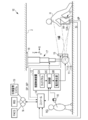
- FIG. 1 shows the configuration of an X-ray imaging system 10 that uses X-rays as radiation.
- the X-ray imaging system 10 that uses X-rays as radiation includes an X-ray source 11, a radiation source control device 12, an electronic cassette 13, a console 14, and an optical camera 15.
- the shooting support device is configured by the console 14 and the optical camera 15.
- the X-ray source 11 is an example of a radiation source.
- the electronic cassette 13 is an example of a radiographic image detector.
- the electronic cassette 13 is arranged at a position facing the X-ray source 11.
- the subject H By arranging the subject H between the X-ray source 11 and the electronic cassette 13, it is possible to take an X-ray image of the imaging portion (knee in FIG. 1) of the subject H.
- the X-ray source 11 and the electronic cassette 13 constitute an X-ray imaging apparatus.
- This X-ray imaging apparatus is an example of a radiographic imaging apparatus according to the technique of the present disclosure.
- the electronic cassette 13 may be arranged on a standing shooting table or a lying shooting table.
- the radiologist hereinafter, simply referred to as a technician
- a technician positions the subject H, and then the radiologist RG performs an X-ray imaging operation.
- the X-ray source 11 includes an X-ray tube 11A that generates X-rays and an irradiation field limiter 11B that limits the irradiation field RF, which is a region where X-rays are irradiated.
- the X-ray source 11 may include an irradiation field display light source (not shown) that emits irradiation field display light indicating the irradiation field RF on the X-ray incident surface 13A of the electronic cassette 13.
- the X-ray tube 11A has a filament that emits thermoelectrons and a target that the thermoelectrons emitted from the filament collide with each other to emit X-rays.
- the irradiation field limiter 11B for example, by arranging four lead plates that shield X-rays on each side of the quadrangle, a quadrangular irradiation opening for transmitting X-rays is formed in the center. In this case, the irradiation field limiting device 11B changes the size of the irradiation opening by moving the position of the lead plate, and sets the irradiation field RF.
- the radiation source control device 12 has a touch panel 12A, a voltage generation unit 12B, and a control unit 12C.
- the touch panel 12A is operated by the engineer RG when setting the X-ray irradiation conditions and the size of the irradiation opening of the irradiation field limiting device 11B.
- the X-ray irradiation conditions include the tube voltage applied to the X-ray source 11, the tube current, and the X-ray irradiation time.
- the voltage generating unit 12B generates a tube voltage to be applied to the X-ray tube 11A.
- the control unit 12C sets the tube voltage, the tube current, and the X-ray irradiation time to the values set by the touch panel 12A.
- the control unit 12C has a timer that starts timing when X-rays are generated from the X-ray tube 11A.
- the control unit 12C stops the operation of the X-ray tube 11A, for example, when the time measured by the timer reaches the irradiation time specified by the irradiation conditions. Further, the control unit 12C operates the irradiation field limiting device 11B, and sets the size of the irradiation opening to the size set by the touch panel 12A.
- the irradiation switch 16 is connected to the control unit 12C via a cable or the like.
- the irradiation switch 16 is operated by the engineer RG when starting the irradiation of X-rays.
- the radiation source control device 12 When the irradiation switch 16 is operated, the radiation source control device 12 generates X-rays in the X-ray tube 11A. As a result, X-rays are irradiated toward the irradiation field RF.
- the electronic cassette 13 detects an X-ray image XP based on X-rays emitted from the X-ray source 11 and transmitted through the imaged portion of the subject H.
- the electronic cassette 13 has a wireless communication unit and a battery, and operates wirelessly.
- the electronic cassette 13 wirelessly transmits the detected X-ray image XP to the console 14.
- the X-ray image XP is an example of a radiographic image.
- the electronic cassette 13 of the present embodiment is not a synchronous type that starts operation in response to receiving a control signal from the console 14, but detects X-rays emitted from the X-ray source 11 and automatically controls the operation.
- Asynchronous type synchronous free type
- the electronic cassette 13 has an irradiation start detection function for detecting that X-ray irradiation has been started by detecting X-rays emitted from the X-ray source 11. Further, when the electronic cassette 13 detects the start of X-ray irradiation, the electronic cassette 13 wirelessly transmits the irradiation start detection signal SI to the console 14.
- the irradiation start detection signal SI is an example of a timing signal according to the technique of the present disclosure.
- the X-ray source 11 is suspended vertically downward from the ceiling 2 of the photographing room.
- the X-ray source 11 is held by the suspension holding mechanism 17.
- the suspension holding mechanism 17 is attached to the ceiling 2 via the horizontal moving mechanism 18.
- the suspension holding mechanism 17 holds the X-ray source 11 so as to be able to move up and down in the vertical direction ( ⁇ Z direction).
- the horizontal movement mechanism 18 movably holds the suspension holding mechanism 17 in the X-irradiation axis direction ( ⁇ X direction) and the direction orthogonal to the X irradiation axis direction ( ⁇ Y direction) of the X-ray source 11.
- Motors (not shown) are provided in the suspension holding mechanism 17 and the horizontal moving mechanism 18, respectively, and it is possible to move the X-ray source 11 manually or electrically in each direction.
- the operations of the suspension holding mechanism 17 and the horizontal moving mechanism 18 are controlled by the control unit 12C. Whether to move the X-ray source 11 manually or electrically can be selected by the touch panel 12A. By moving the X-ray source 11, the position of the irradiation field RF can be adjusted.
- the optical camera 15 is an optical digital camera including a CMOS (Complementary Metal Oxide Semiconductor) type image sensor, a CCD (Charge Coupled Device) type image sensor, and the like, and performs photographing based on visible light as an example. ..
- the optical camera 15 enables still image shooting and moving image shooting.
- the optical camera 15 is an example of a moving image capturing device according to the technique of the present disclosure.
- the optical axis of the optical camera 15 is parallel to the irradiation axis of X-rays passing through the center of the irradiation field RF.
- the optical camera 15 generates an optical image by optically photographing a region including the irradiation field RF.
- the optical image is an image showing an imaged portion of the subject H located in the irradiation field RF.
- the optical image is, for example, a color still image or moving image.
- the optical camera 15 is attached to the outer peripheral portion of the X-ray source 11.
- the optical camera 15 may not be attached to the outer peripheral portion of the X-ray source 11, or may be built in the X-ray source 11. Further, in the optical camera 15, the objective lens and the image pickup element may be formed separately. In this case, even if the objective lens is arranged on the outer peripheral portion of the X-ray source 11 and the image sensor is built in a portion other than the X-ray source 11 (for example, an arm supporting the X-ray source 11). good.
- the optical camera 15 is connected to the console 14 by wire or wirelessly.
- the console 14 controls the shooting operation of the optical camera 15 by functioning as a shooting control device.
- the console 14 causes the optical camera 15 to shoot a still image in conjunction with the irradiation start detection signal SI transmitted from the electronic cassette 13, and also causes the optical camera 15 to shoot a moving image during the shooting preparation period before the start of X-ray shooting.
- the console 14 is installed in an operation room adjacent to a photographing room in which the X-ray source 11 is installed.
- the console 14 When the console 14 receives the irradiation start detection signal SI from the electronic cassette 13, it transmits a still image shooting instruction signal to the optical camera 15.
- the optical camera 15 captures a still image of a region including the irradiation field RF in response to a still image capture instruction signal input from the console 14.
- the optical image (hereinafter, referred to as still image SP) obtained by this still image shooting is transmitted to the console 14.
- the console 14 transmits a moving image shooting start signal to the optical camera 15 when the engineer RG performs an operation to start shooting preparation.
- the optical camera 15 starts moving image shooting in the region including the irradiation field RF in response to the moving image shooting start signal input from the console 14.
- the optical image (hereinafter referred to as a moving image MP) obtained by this moving image shooting is transmitted to the console 14 as a so-called live view image in real time at the time of moving image shooting.
- the console 14 is connected to the RIS (Radiology Information System), the PACS (Picture Archiving and Communication System), and the photo loss management system 19 provided in the X-ray imaging system 10 via the network N.
- the console 14 has a function of performing X-ray photography by the operation of the engineer RG based on the photographing order and various information acquired from the RIS. Further, the console 14 has a function of transmitting the X-ray image XP received from the electronic cassette 13 to the PACS after the X-ray imaging.
- the console 14 has a function of transmitting the X-ray image XP determined by the engineer RG to the copying loss management system 19 after the X-ray shooting.
- the copying loss management system 19 collects the X-ray image XP determined to be copying loss and analyzes the cause of the copying loss.
- FIG. 2 shows the configuration of the electronic cassette 13.
- the electronic cassette 13 includes a sensor panel 20, a circuit unit 21, and a rectangular parallelepiped-shaped portable housing 22 that accommodates the sensor panel 20.
- the housing 22 has a size conforming to the international standard ISO (International Organization for Standardization) 4090: 2001, which is substantially the same as, for example, a film cassette, an IP (Imaging Plate) cassette, and a CR (Computed Radiography) cassette.
- ISO International Organization for Standardization
- the electronic cassette 13 is positioned so that the X-ray incident surface 13A, which is the upper surface of the housing 22, faces the X-ray source 11, and the X-ray incident surface 13A is irradiated with X-rays.
- the housing 22 also informs the operating state of the electronic cassette 13 such as a switch for switching the main power on / off, the remaining battery usage time, and the shooting ready state. An indicator is provided.
- the sensor panel 20 is composed of a scintillator 20A and a photodetector substrate 20B.
- the scintillator 20A and the photodetector substrate 20B are laminated in the order of the scintillator 20A and the photodetector substrate 20B when viewed from the X-ray incident surface 13A side.
- the scintillator 20A has a phosphor such as CsI: Tl (thallium-activated cesium iodide) or GOS (Gd 2 O 2 S: Tb, terbium-activated gadolinium oxysulfide), and X is incident through the X-ray incident surface 13A. Converts the line into visible light and emits it.
- a sensor panel in which the photodetector substrate 20B and the scintillator 20A are laminated in this order when viewed from the X-ray incident surface 13A side may be used. Further, a direct conversion type sensor panel that directly converts X-rays into signal charges by a photoconductive film such as amorphous selenium may be used.
- the photodetector substrate 20B detects visible light emitted from the scintillator 20A and converts it into electric charges.
- the circuit unit 21 controls the drive of the photodetection board 20B and generates an X-ray image XP based on the electric charge output from the photodetection board 20B.
- FIG. 3 shows the configuration of the photodetector substrate 20B.
- the optical detection substrate 20B includes a pixel region 30, a gate driver 31, a signal processing circuit 32, an irradiation start detection unit 33, a control unit 34, and a communication interface (I / F) 35.
- the pixel region 30 has a plurality of normal pixels 40A arranged on a matrix along the X and Y directions orthogonal to each other.
- the normal pixel 40A is a pixel for generating an X-ray image for detecting X-rays and generating an X-ray image XP.
- a detection pixel 40B is provided in the pixel area 30, in addition to the normal pixel 40A.
- the detection pixel 40B is a pixel for detecting the start of irradiation for detecting the start of irradiation of X-rays.
- the normal pixel 40A has a photoelectric conversion unit 41 that generates and stores electric charges by photoelectric conversion of visible light converted by a scintillator, and a TFT 42 as a switching element.
- the photoelectric conversion unit 41 has, for example, a PIN (p-intrinsic-n) type semiconductor layer, an upper electrode arranged on the upper side of the semiconductor layer, and a lower electrode arranged on the lower side of the semiconductor layer. A bias voltage is applied to the upper electrode.
- the lower electrode is connected to a TFT (Thin Film Transistor) 42.
- the detection pixel 40B has a photoelectric conversion unit 41 and a TFT 42, similarly to the normal pixel 40A. However, in the detection pixel 40B, the source electrode and the drain electrode of the TFT 42 are short-circuited. Hereinafter, when it is not necessary to distinguish between the normal pixel 40A and the detection pixel 40B, these are simply referred to as the pixel 40.
- the pixel region 30 has a plurality of scanning lines 43 extending in the X direction and a plurality of signal lines 44 extending in the Y direction.
- the scanning line 43 and the signal line 44 are wired in a grid pattern.
- the pixels 40 are connected to the intersections of the scanning line 43 and the signal line 44, respectively.
- the gate electrode of the TFT 42 is connected to the scanning line 43
- the source electrode of the TFT 42 is connected to the signal line 44.
- the drain electrode of the TFT 42 is connected to the photoelectric conversion unit 41.
- Each scanning line 43 is commonly connected to the pixel 40 for one pixel line.
- Each signal line 44 is commonly connected to pixels 40 for one pixel row.
- Each scanning line 43 is connected to a gate driver 31.
- Each signal line 44 is connected to a signal processing circuit 32.
- the gate driver 31 sequentially supplies gate pulses as scanning signals to each scanning line 43.
- the gate pulse supplied to the scanning line 43 is applied to the gate electrode of the TFT 42 included in the pixel 40 connected to the scanning line 43.
- the electric charge accumulated in the photoelectric conversion unit 41 of the normal pixel 40A is output to the signal line 44 when the TFT 42 is turned on. Since the source electrode and the drain electrode of the TFT 42 are short-circuited in the detection pixel 40B, the electric charge generated in the photoelectric conversion unit 41 of the detection pixel 40B is output to the signal line 44 regardless of the switching state of the TFT 42. ..
- the signal processing circuit 32 has an integrator as a charge amplifier, a CDS (correlated double sampling) circuit, and an analog / digital (A / D) converter.
- the signal processing circuit 32 integrates the charges input from each pixel 40 via the signal line 44 with an integrator, and then performs correlated double sampling with a CDS circuit. Then, the signal processing circuit 32 converts the pixel signal from which the reset noise component has been removed by the correlated double sampling into a digital signal by the A / D converter.
- the signal processing circuit 32 generates an X-ray image XP based on a pixel signal for one frame read from each normal pixel 40A in the pixel area 30.
- the irradiation start detection unit 33 detects the start of X-ray irradiation based on the pixel signal output from the detection pixel 40B via the signal processing circuit 32.
- the irradiation start detection unit 33 monitors the pixel signal output from the detection pixel 40B. As shown in FIG. 4, the irradiation start detection unit 33 determines that X-ray irradiation has started when the pixel signal output from the detection pixel 40B exceeds the threshold value Vth, and determines that the irradiation start detection signal SI Is output.
- the irradiation start detection unit 33 performs irradiation start detection based on the maximum value of the pixel signals output from the plurality of detection pixels 40B.
- the irradiation start detection unit 33 may perform irradiation start detection based on an average value, a total value, or the like instead of the maximum value. Further, the irradiation start detection unit 33 may perform irradiation start detection based on the temporal change rate of the pixel signal.
- the control unit 34 is composed of a microcomputer, and includes a CPU (Central Processing Unit), a memory, and a storage device.
- the control unit 34 controls for X-ray image capture by executing the program stored in the memory on the CPU.
- the control unit 34 controls each unit of the gate driver 31, the signal processing circuit 32, the irradiation start detection unit 33, and the communication I / F 35.
- the control unit 34 controls the gate driver 31 and the signal processing circuit 32 to reset the electric charge stored in the normal pixel 40A. .. Specifically, the control unit 34 supplies a gate pulse to each scanning line 43 from the gate driver 31. From this, the accumulated charge of each normal pixel 40A is output to the signal line 44, and the charge is discarded by the signal processing circuit 32. do. After the reset operation is completed, the control unit 34 turns off all the TFTs 42 to put the normal pixel 40A into the charge accumulation state.
- the control unit 34 controls the gate driver 31 after the predetermined X-ray irradiation time elapses after putting the normal pixel 40A into the charge accumulation state, and reads the pixel signal from the normal pixel 40A to the signal processing circuit 32. , X-ray image XP is generated.
- the control unit 34 When the irradiation start detection unit 33 detects the start of X-ray irradiation, the control unit 34 outputs the irradiation start detection signal SI to the console 14 via the communication I / F 35. Further, the control unit 34 outputs the X-ray image XP to the console 14 via the communication I / F 35 after the X-ray image XP is generated by the signal processing circuit 32.
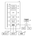
- the console 14 has a display 50, an input device 51, a CPU 52, a memory 53, a storage device 54, and a communication unit 55. These are interconnected via a data bus 56.
- the display 50 is a display unit that displays various operation screens, X-ray image XP, and optical images (still image SP and moving image MP) equipped with operation functions by GUI (Graphical User Interface).
- the input device 51 is an input operation unit including a touch panel, a keyboard, and the like.
- the storage device 54 is, for example, an HDD (Hard Disk Drive) array, which is built in the console 14 or externally connected to the console 14. External connections are connected through cables or networks.
- the storage device 54 stores control programs such as an operating system, various application programs, and various data associated with these programs.
- the memory 53 is a work memory for the CPU 52 to execute a process.
- the CPU 52 collectively controls each part of the console 14 by loading the program stored in the storage device 54 into the memory 53 and executing processing according to the program.
- the communication unit 55 transmits and receives various data such as an X-ray image XP and an optical image (still image SP and moving image MP) between the electronic cassette 13 and the optical camera 15. Further, the communication unit 55 communicates with the control unit 12C of the radiation source control device 12.
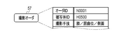
- the console 14 accepts the input of the shooting order 57 shown in FIG.
- the imaging order 57 is information for instructing the technician RG to perform X-ray imaging, for example, from a imaging requester in a clinical department.
- the shooting order 57 is delivered from the RIS to the console 14.
- the shooting order 57 has items such as an order ID (Identification Data), a subject ID, and a shooting technique.
- the order ID is a symbol or number that identifies each shooting order 57, and is automatically assigned by the RIS.
- the subject ID of the subject H to be photographed is recorded.
- the subject ID is a symbol or number that identifies each subject H.
- the shooting technique is information on the shooting part of the subject H and the posture and orientation of the shooting part.
- the imaging site includes the head, cervical spine, chest, abdomen, hands, fingers, elbows, and the like.
- the posture is the posture of the subject H such as a standing position, a lying position, or a sitting position.
- the orientation is the orientation of the subject H with respect to the X-ray source 11 such as the front surface, the side surface, or the back surface.
- the photographing order 57 includes items of subject information (patient information) such as the name, gender, age, height, and weight of the subject H.
- the condition table 58 shown in FIG. 7 is stored in the storage device 54 of the console 14. In the condition table 58, the irradiation conditions corresponding to each imaging technique are registered in association with each other.
- the console 14 displays the shooting order list, which lists the contents of the shooting order 57 shown in FIG. 6, on the display 50 by the operation of the engineer RG.
- the engineer RG can browse the shooting order list and confirm the contents of the shooting order 57. Further, the console 14 displays the contents of the condition table 58 shown in FIG. 7 on the display 50.
- the engineer RG can select and set irradiation conditions that match the imaging technique specified in the imaging order 57.
- the console 14 wirelessly transmits a condition setting signal including various information such as irradiation conditions set by the engineer RG, an order ID, and a console ID as console identification information to the electronic cassette 13.
- the console 14 stores the X-ray image XP received from the electronic cassette 13 in the storage device 54 as a storage unit, for example, as an image file in a format compliant with the DICOM (Digital Imaging and Communication in Medicine) standard.
- image file the X-ray image XP and the incidental information are associated with one image ID.
- Ancillary information includes order ID, subject ID, patient information, imaging technique, irradiation conditions, and the like.
- the still image SP obtained by the optical camera 15 taking a still image in conjunction with the irradiation start detection signal SI includes the image ID (X-ray image) of the X-ray image XP obtained by the X-ray photography.
- An image ID (optical image ID) associated with the ID) is attached.
- the X-ray image XP and the still image SP obtained during one X-ray imaging are stored in the storage device 54 in association with the X-ray image ID and the optical image ID.
- the doctor mainly diagnoses the joint cavity JC of the knee based on the X-ray image XP. Therefore, the joint cavity JC needs to be clearly depicted in the X-ray image XP.
- FIG. 9 shows various functions configured in the CPU 52.
- the operation program 60 is stored in the storage device 54.
- the condition table 58 shown in FIG. 7 is also stored in the storage device 54.
- a plurality of functional units are configured in the CPU 52 by executing the operation program 60.
- the operation program 60 causes the CPU 52 to function as a still image shooting instruction unit 61, a still image acquisition unit 62, an association unit 63, a moving image shooting instruction unit 64, a moving image acquisition unit 65, a superimposition processing unit 66, and a display control unit 67.
- the still image shooting instruction unit 61 transmits an irradiation start detection signal SI transmitted from the electronic cassette 13 in response to the fact that the irradiation switch 16 is pressed and the X-ray irradiation from the X-ray source 11 to the electronic cassette 13 is started. , Receives via the communication unit 55. The still image shooting instruction unit 61 instructs the optical camera 15 to perform still image shooting in response to receiving the irradiation start detection signal SI from the electronic cassette 13.
- the still image acquisition unit 62 acquires the still image SP generated by the optical camera 15 taking a still image.
- the still image SP acquired by the still image acquisition unit 62 is input to the association unit 63. Further, in the association unit 63, an X-ray image XP detected by the electronic cassette 13 based on the X-rays emitted from the X-ray source 11 in response to the pressing of the irradiation switch 16 is transmitted via the communication unit 55. Is entered.
- the association unit 63 associates the still image SP input to the still image acquisition unit 62 with the X-ray image XP input from the electronic cassette 13 and stores them in the storage device 54 as shown in FIG.
- the association unit 63 associates the associated still image SP and the X-ray image XP with incidental information (see FIG. 8) such as the above-mentioned patient information and stores the information in the storage device 54.
- the movie shooting instruction unit 64 transmits a movie shooting start signal instructing the optical camera 15 to start movie shooting in response to the re-shooting preparation start signal RS being input from the input device 51.
- the engineer RG confirms the X-ray image XP acquired by X-ray imaging, and if it determines that the image is not captured, operates the input device 51 to shift the imaging support device to the preparation mode for re-imaging. Let me. When the imaging technique is "knee / flexion / lateral", the technician RG determines that the image is lost when, for example, the joint cavity JC of the knee is not clearly depicted in the X-ray image XP.
- the moving image acquisition unit 65 acquires the moving image MP generated by the optical camera 15 taking a moving image in real time for each frame.
- the moving image acquisition unit 65 acquires an optical image for each frame and outputs a moving image MP composed of the acquired plurality of frames.
- the moving image MP output from the moving image acquisition unit 65 is input to the superimposition processing unit 66 for each frame.
- the superimposition processing unit 66 acquires the still image SP stored in the storage device 54, and superimposes the still image SP on each frame of the moving image MP as shown in FIG.
- the superimposition processing unit 66 inputs the superimposition image TP generated by superimposing the moving image MP and the still image SP to the display control unit 67 for each frame.
- the display control unit 67 displays the superimposed image TP on the display 50 frame by frame. That is, the display control unit 67 superimposes the still image SP on the moving image MP and displays it on the display 50 in real time.
- the still image SP in the superimposed image TP is associated with the X-ray image XP that the engineer RG has determined to be a photo loss, and indicates the position of the subject H at the time of the photo loss.
- the moving image MP in the superimposed image TP indicates the current position of the subject H during preparation for re-shooting. Therefore, the engineer RG can confirm the current position of the subject H with respect to the time of copying loss by confirming the superimposed image TP displayed in real time on the display 50.
- the moving image shooting of the optical camera 15 ends in response to the reception of the still image shooting execution instruction from the still image shooting instruction unit 61 described above. After the moving image shooting is completed, the moving image MP is discarded without being saved in the storage device 54. This is for the purpose of preventing the moving image MP from being saved in the storage device 54, that is, protecting privacy when unnecessary information is displayed on the moving image MP during the preparation for shooting.
- the still image acquisition unit 62 may acquire one frame of the moving image MP as the still image SP.
- the display control unit 67 displays a console screen on the display 50, which enables the engineer RG to perform various operations such as selection of the shooting order 57 using the input device 51. Further, the display control unit 67 displays the X-ray image XP or the superimposed image TP in the console screen.
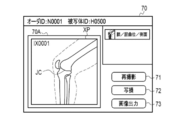
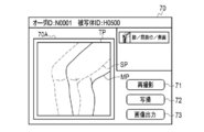
- FIG. 11 shows an example of a console screen displayed on the display 50 by the display control unit 67.
- the console screen 70 is provided with an image display area 70A for displaying an image such as an X-ray image XP or a superposed image TP.
- a first operation button 71 for performing re-shooting a first operation button 71 for performing re-shooting
- a second operation button 72 for outputting the X-ray image XP determined to be a copying loss to the copying loss management system 19, and an X-ray.
- a third operation button 73 for outputting the image XP to the PACS is displayed.
- the first operation button 71, the second operation button 72, and the third operation button 73 are operated by a touch panel formed on the screen of the display 50.
- FIG. 11 shows a display example of the console screen 70 after X-ray photography.
- the X-ray image XP obtained by X-ray photography is displayed in the image display area 70A.
- the engineer RG determines that the X-ray image XP is not an image suitable for diagnosis and re-imaging is necessary (that is, copying loss)
- the engineer RG presses the second operation button 72 to obtain the X-ray image.
- XP can be transmitted to the copying loss management system 19.
- the engineer RG can start the X-ray imaging system 10 to start the imaging preparation operation for reimaging by pressing the first operation button 71.
- the engineer RG determines that the X-ray image XP is an image suitable for diagnosis and re-imaging is unnecessary, the engineer RG presses the third operation button 73 to PACS the X-ray image XP. Can be sent to.
- the console 14 When the console 14 transmits the X-ray image XP to the outside such as the photo loss management system 19 or the PACS, the console 14 provides incidental information such as patient information to the still image SP and the X-ray image XP associated with the association unit 63. It is preferable to output a file (see FIG. 8) associated with.
- FIG. 12 shows a display example of the console screen 70 in the shooting preparation operation for reshooting.
- the superimposed image TP in which the still image SP is superimposed on the moving image MP is displayed in the image display area 70A.
- the still image SP indicates the position of the subject H at the time of shooting loss.
- the moving image MP indicates the current position of the subject H in the shooting preparation operation.
- the engineer RG can position the subject H while referring to the still image SP indicating the position of the subject H at the time of copying loss.
- the engineer RG confirms the contents of the photographing order 57 on the display 50 and sets the irradiation conditions using the input device 51 and the touch panel 12A prior to the photographing.
- the engineer RG positions the X-ray source 11, the electronic cassette 13, and the subject H according to the photographing technique included in the photographing order 57.
- the shooting technique is "knee / flexion / side”.
- the engineer RG bends one leg of the subject H and positions the subject H so that the side surface of the knee faces the X-ray incident surface 13A of the electronic cassette 13 and the knee is located at the center of the irradiation field RF ( (See FIG. 1).
- the still image shooting instruction unit 61 determines whether or not the irradiation start detection signal SI has been received from the electronic cassette 13 (step S10).
- the irradiation start detection unit 33 of the electronic cassette 13 responds to the start of irradiation of X-rays from the X-ray source 11 to the electronic cassette 13 by pressing the irradiation switch 16 by the engineer RG. This is a timing signal that detects the start of X-ray irradiation and is transmitted from the electronic cassette 13 to the console 14.
- the electronic cassette 13 detects the X-ray image XP of the subject H based on the X-rays transmitted through the subject H.
- the still image shooting instruction unit 61 When the still image shooting instruction unit 61 receives the irradiation start detection signal SI (step S10: YES), the still image shooting instruction unit 61 instructs the optical camera 15 to execute the still image shooting (step S11).
- the still image acquisition unit 62 acquires the still image SP generated by the optical camera 15 taking a still image (step S12). Further, the console 14 acquires the X-ray image XP detected by the electronic cassette 13 (step S13).
- the association unit 63 associates the acquired X-ray image XP with the still image SP and saves it in the storage device 54 (step S14).
- the display control unit 67 displays the X-ray image XP stored in the storage device 54 in the image display area 70A of the console screen 70 (step S15).
- the CPU 52 determines whether or not the engineer RG has been instructed to output an image by pressing the third operation button 73 (step S16).
- the engineer RG confirms the X-ray image XP (see FIG. 11) displayed in the image display area 70A, and when it is determined that re-shooting is unnecessary, the engineer RG instructs the image output by pressing the third operation button 73. I do.
- the CPU 52 determines that the third operation button 73 has been pressed (step S16: YES)
- the CPU 52 outputs the X-ray image XP stored in the storage device 54 to the PACS (step S25), and ends the process.
- the engineer RG confirms the X-ray image XP displayed in the image display area 70A, and when it is determined that re-imaging is necessary, the engineer RG presses the second operation button 72 to obtain the X-ray image XP. Is instructed to be transmitted to the copying loss management system 19. After that, the engineer RG instructs the start of preparation for re-shooting by pressing the first operation button 71. When the first operation button 71 is pressed, the input device 51 generates a re-shooting preparation start signal RS and transmits it to the moving image shooting instruction unit 64.
- step S16 determines whether or not the re-shooting preparation start signal RS has been received from the input device 51. Determine (step S17).
- step S17 receives the re-shooting preparation start signal RS
- step S18 transmits the moving image shooting start signal to the optical camera 15 (step S18).
- the moving image acquisition unit 65 acquires the moving image MP generated by the optical camera 15 taking a moving image for each frame (step S19).
- the superimposition processing unit 66 acquires the still image SP stored in the storage device 54, and superimposes the still image SP on the frame of the moving image MP acquired by the moving image acquisition unit 65 to superimpose the superimposed image.
- Generate TP step S20.
- the display control unit 67 displays the superposed image TP generated by the superimposing processing unit 66 in the image display area 70A of the console screen 70 (step S23).
- the engineer RG positions the subject H while referring to the still image SP indicating the position of the subject H at the time of image loss. Can be done.
- the engineer RG gives an instruction to execute X-ray photography by pressing the irradiation switch 16.
- the still image shooting instruction unit 61 determines whether or not the irradiation start detection signal SI has been received from the electronic cassette 13 (step S24). While the still image shooting instruction unit 61 does not receive the irradiation start detection signal SI (step S24: NO), the process is returned to step S19, and the moving image acquisition unit 65 acquires the next frame of the moving image MP. Until the irradiation start detection signal SI is received, the processes of steps S19 to S24 are repeatedly executed. As a result, the superimposed image TP in which the still image SP is superimposed on the moving image MP is displayed in real time in the image display area 70A.
- step S24 YES
- the still image shooting instruction unit 61 executes still image shooting with respect to the optical camera 15.
- Step S11 When the optical camera 15 receives an instruction to execute the still image shooting, the optical camera 15 ends the moving image shooting and performs the still image shooting. After that, the same process is executed.
- the irradiation switch 16 After the irradiation switch 16 is pressed by the engineer RG, it takes a certain amount of time for the radiation source control device 12 to generate X-rays in the X-ray tube 11A. Therefore, after the irradiation switch 16 is pressed, X-rays are emitted. There is a time lag before the start of irradiation. In particular, when the irradiation switch 16 is a two-step switch capable of performing a two-step pressing operation of half-pressing and full-pressing, the time lag becomes large.
- the irradiation switch 16 is a two-stage switch, for example, the warm-up of the X-ray tube 11A is started in response to the half-pressing of the irradiation switch 16, and after the warm-up is completed, the irradiation switch 16 is set. When fully pressed, the X-ray tube 11A generates X-rays. Since it takes a certain amount of time to warm up the X-ray tube 11A, the time lag becomes large.
- the still image shooting by the optical camera 15 is executed at the timing when the irradiation switch 16 is pressed, the still image shooting is performed before the actual X-ray shooting is performed. Therefore, the acquisition times of the X-ray image XP associated with the association unit 63 and stored in the storage device 54 and the still image SP are different from each other. If the acquisition time of the X-ray image XP and the still image SP is different, the still image SP in the superimposed image TP is not an image that accurately represents the position of the subject H at the time of loss of image, and therefore the subject at the time of re-shooting. The positioning accuracy of H is lowered, and there is a possibility that image loss may occur again.
- the CPU 52 executes still image shooting by the optical camera 15 at the timing when the irradiation start detection signal SI is received from the electronic cassette 13 instead of the timing when the irradiation switch 16 is pressed. I'm letting you.
- the deviation of the acquisition time between the X-ray image XP and the still image SP associated by the association unit 63 is reduced, and the positioning accuracy of the subject H at the time of re-shooting is improved.
- the possibility of re-imaging due to re-imaging is reduced, and the amount of exposure of the subject H to X-rays can be suppressed.
- the engineer RG determines the necessity of re-shooting using only the X-ray image XP
- the X-ray image XP that does not need to be re-photographed is mistakenly determined to be a copying loss, so that unnecessary re-shooting is performed. There is a possibility of doing. Further, depending on the physical characteristics of the subject H and the like, there may be no possibility of improvement even after re-shooting. In such a case, unnecessary re-shooting may be repeated.
- the shooting support device having the above configuration the X-ray image XP and the still image SP with little deviation in the acquisition time are acquired. Therefore, by using the still image SP captured at the same time as the X-ray image XP for the determination of re-imaging, the necessity of re-imaging can be determined more accurately.
- the effect of the imaging support device having the above configuration regarding the positioning of the subject H will be described with reference to FIGS. 14 and 15.
- the joint cavity JC needs to be clearly depicted in the X-ray image XP, but since X-rays are a bundle of lines radiating from the focal point of the X-ray source 11. , The incident angle of X-rays changes due to a slight misalignment of the joint, and the depiction of the joint cavity JC becomes unclear. If the depiction of the joint cavity JC is unclear, the image will be lost and re-imaging will be required.
- the engineer RG can accurately grasp the position of the subject H at the time of shooting loss. Cannot make fine adjustments. If the engineer RG repositions the subject H from the beginning, there is a high possibility that the subject H will be positioned at the same position again, and the image loss will occur again. Further, even if the subject H is positioned by using an optical camera or the like before the X-ray photography, if the shooting loss occurs, the engineer RG cannot grasp the position of the subject H at the time of the shooting loss. , There is a high possibility that shooting loss will occur again, and re-shooting will be repeated.
- an optical image (still image SP) showing the subject H is acquired together with the X-ray image XP in conjunction with the start of X-ray irradiation.
- the engineer RG can easily grasp the position of the subject H at the time of the image loss. Therefore, the engineer RG can position the subject H at the position at the time of shooting loss and then finely adjust the position of the subject H from the position at the time of shooting loss based on the reason for the shooting loss or the like.
- a good X-ray image XP can be obtained by finely adjusting the position of the subject H and then performing re-imaging.
- the superimposed image TP in which the optical image (still image SP) acquired in conjunction with the start of X-ray irradiation and the current optical image (moving image MP) of the subject H are superimposed is displayed in real time. do. Even if the subject H moves significantly from the time of shooting loss, the engineer RG can more easily grasp the position of the subject H at the time of shooting loss based on the still image SP in the superimposed image TP.
- the still image acquisition unit 62 acquires the still image SP obtained by the optical camera 15 receiving an instruction from the still image shooting instruction unit 61 and performing the still image shooting.
- the still image acquisition unit 62 extracts one frame from the moving image MP based on the irradiation start detection signal SI transmitted from the electronic cassette 13, and extracts the extracted frame into the still image SP. Get as.
- the still image acquisition unit 62 receives the irradiation start detection signal SI from the electronic cassette 13 from the plurality of frames F constituting the moving image MP acquired by the moving image acquisition unit 65.
- the frame F corresponding to the time is extracted.
- the still image acquisition unit 62 sets the extracted frame F as the still image SP, and discards the remaining frames F other than the extracted frame F.
- the still image acquisition unit 62 may store the time when the irradiation start detection signal SI is received from the electronic cassette 13 and extract the frame F from the moving image MP after the end of the X-ray photography.
- the moving image MP acquired by the moving image acquisition unit 65 is stored in the storage device 54 or the like, the frame F corresponding to the reception time of the irradiation start detection signal SI is extracted as the still image SP, and then the moving image MP is stored. Erase from the device 54 or the like.
- the still image SP acquired by the still image acquisition unit 62 is associated with the X-ray image XP by the association unit 63 and stored in the storage device 54, as in the first embodiment.
- the asynchronous electronic cassette 13 is used as the radiographic image detector, but in the second embodiment, the synchronous electronic cassette 13B is used as the radiographic image detector.
- the electronic cassette 13B starts operation in response to receiving a control signal from the console 14. Therefore, the electronic cassette 13B does not include the irradiation start detection unit 33.
- the console 14 transmits a preparation request signal EQU requesting preparation for X-ray detection to the electronic cassette 13B before starting irradiation of X-rays from the X-ray source 11.
- the electronic cassette 13B Upon receiving the preparation request signal EQU, the electronic cassette 13B performs the above-mentioned reset operation and the like, and then transmits a preparation completion signal RDY indicating that the X-ray detection preparation is completed to the console 14.
- the console 14 causes the optical camera 15 to take a still image in conjunction with the ready signal RDY transmitted from the electronic cassette 13.
- the preparation completion signal RDY is an example of a timing signal according to the technique of the present disclosure.
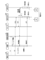
- FIG. 17 is a sequence diagram showing the operation timing of each part of the X-ray imaging system according to the second embodiment.
- the irradiation switch 16 is the above-mentioned two-stage switch.
- the irradiation switch 16 transmits the first operation signal S1 to the radiation source control device 12.
- the radiation source control device 12 Upon receiving the first operation signal S1, the radiation source control device 12 causes the X-ray source 11 to start warming up the X-ray tube 11A.
- the second operation signal S2 is transmitted from the irradiation switch 16 to the radiation source control device 12.
- the console 14 transmits a preparation request signal EQU to the electronic cassette 13B.
- the electronic cassette 13B transmits a preparation completion signal RDY to the console 14 after performing a reset operation or the like.
- the console 14 Upon receiving the ready signal RDY, the console 14 causes the X-ray source 11 to start irradiating X-rays.
- the console 14 receives the preparation completion signal RDY, the still image shooting instruction unit 61 instructs the optical camera 15 to execute the still image shooting.
- the electronic cassette 13B starts charge accumulation for X-ray photography after the lapse of the predetermined time T after transmitting the preparation request signal EQU to the console 14.
- the default time T is a value of 0 or more.
- the optical camera 15 After receiving the execution instruction of the still image shooting, the optical camera 15 starts the charge accumulation for the still image shooting.
- the console 14 transmits the irradiation end signal STP to the electronic cassette 13B after the predetermined X-ray irradiation time has elapsed.
- the electronic cassette 13B Upon receiving the irradiation end signal STP, the electronic cassette 13B performs a read-out operation to generate an X-ray image XP.
- the optical camera 15 generates a still image SP by performing a read operation after the elapse of a predetermined exposure time after starting charge accumulation.
- the console 14 causes the optical camera 15 to take a still image based on the irradiation start detection signal SI transmitted from the electronic cassette 13.
- the console 14 causes the optical camera 15 to take a still image based on a signal transmitted from an automatic exposure controller provided separately from the electronic cassette 13.
- FIG. 18 shows the configuration of the X-ray imaging system according to the third embodiment.
- an AEC (Automatic Exposure Control) sensor 80 as an automatic exposure controller is provided in the vicinity of the electronic cassette 13.
- the electronic cassette 13 is held on the photographing table 81.
- the shooting table 81 is a shooting table such as a standing shooting table or a lying shooting table.
- the AEC sensor 80 is held on the photographing table 81 and is arranged on the front side or the back side of the electronic cassette 13.
- the AEC sensor 80 is a sensor that measures the dose of X-rays that have passed through the subject H, and transmits the dose detection signal Sd to the console 14.
- the console 14 supplies the detection signal Sd to the control unit 12C of the radiation source control device 12.
- the control unit 12C stops the X-ray irradiation by the X-ray source 11 when the cumulative dose reaches the target dose based on the dose detection signal Sd.
- the X-ray irradiation is stopped even before the irradiation time included in the preset X-ray irradiation conditions is reached.
- the dose detection signal Sd transmitted from the AEC sensor 80 to the console 14 is also supplied to the still image shooting instruction unit 61.
- the still image shooting instruction unit 61 instructs the optical camera 15 to execute still image shooting in response to receiving the detection signal Sd.
- the detection signal Sd is an example of a radiation detection signal output from the automatic exposure controller.
- Each of the X-ray imaging systems according to the above embodiments is characterized in that the optical image acquired by the optical camera is associated with the radiation image based on the timing signal transmitted from the radiation image detector side.
- the optical image acquired by the optical camera is associated with the radiation image based on the timing signal transmitted from the radiation image detector side.
- the technique of the present disclosure can be applied not only to X-rays but also to a system for photographing a subject using other radiation such as ⁇ -rays.
- various processes such as a still image shooting instruction unit 61, a still image acquisition unit 62, an association unit 63, a moving image shooting instruction unit 64, a moving image acquisition unit 65, a superimposition processing unit 66, and a display control unit 67.
- the hardware structure of the processing unit that executes the above is various processors as shown below.
- processors include a CPU, a programmable logic device (PLD), a dedicated electric circuit, and the like.
- a CPU is a general-purpose processor that executes software (program) and functions as various processing units.
- PLD is a processor such as FPGA (Field Programmable Gate Array) whose circuit configuration can be changed after manufacturing.
- a dedicated electric circuit is a processor having a circuit configuration designed exclusively for executing a specific process such as an ASIC (Application Specific Integrated Circuit).
- One processing unit may be composed of one of these various processors, or may be composed of a combination of two or more processors of the same type or different types (for example, a plurality of FPGAs or a combination of a CPU and an FPGA). May be done. Further, a plurality of processing units may be configured by one processor. As an example of configuring a plurality of processing units with one processor, first, there is a form in which one processor is configured by a combination of one or more CPUs and software, and this processor functions as a plurality of processing units. ..
- SoC System On Chip
- the various processing units are configured by using one or more of the above-mentioned various processors as a hardware-like structure.
- the present invention is not limited to each of the above embodiments, and various configurations can be adopted as long as the gist of the present invention is not deviated. Further, in addition to the program, the present invention extends to a computer-readable storage medium that stores the program non-temporarily.
Landscapes
- Health & Medical Sciences (AREA)
- Life Sciences & Earth Sciences (AREA)
- Medical Informatics (AREA)
- Engineering & Computer Science (AREA)
- Physics & Mathematics (AREA)
- Public Health (AREA)
- Veterinary Medicine (AREA)
- General Health & Medical Sciences (AREA)
- Pathology (AREA)
- Biophysics (AREA)
- Biomedical Technology (AREA)
- Heart & Thoracic Surgery (AREA)
- Molecular Biology (AREA)
- Surgery (AREA)
- Animal Behavior & Ethology (AREA)
- Nuclear Medicine, Radiotherapy & Molecular Imaging (AREA)
- Radiology & Medical Imaging (AREA)
- Optics & Photonics (AREA)
- High Energy & Nuclear Physics (AREA)
- Mathematical Physics (AREA)
- Apparatus For Radiation Diagnosis (AREA)
Abstract
放射線源と、放射線源から照射され被写体を透過した放射線に基づいて被写体の放射線画像を検出する放射線画像検出器とを有する放射線撮影装置に用いられる撮影支援装置であって、放射線源から被写体に照射される放射線の照射野を含む領域を光学的に撮影することにより光学画像を出力する光学カメラと、少なくとも1つのプロセッサとを備え、プロセッサは、放射線画像検出器側から送信されるタイミング信号に基づいて、光学カメラにより取得された光学画像を放射線画像に関連付ける。
Description
本開示の技術は、撮影支援装置、その作動方法、及び作動プログラムに関する。
医療分野で用いられる放射線撮影システムでは、撮影準備として、放射線技師又は医師(以下、技師等という。)により被写体の撮影部位の位置決めが行われた後、技師等の指示に基づき放射線撮影が行われる。しかし、放射線の照射野に対する撮影部位の位置決め後、放射線撮影が行われる前に、被写体が動くことにより撮影部位の位置ずれが生じ、所望する撮影部位の画像が得られないことがある。このように、放射線撮影により所望の放射線画像が得られなかったこと、すなわち放射線撮影に失敗したことは「写損」と称される。写損が生じた場合は再撮影が行われる。また、技師等が、再撮影が不要な放射線画像を誤って写損と判断することにより、不必要な再撮影が行われることもある。再撮影は、時間も手間も掛り、被写体への被ばく量も増大するため、少ない方がよい。
このような再撮影に関連して、特開2008-206740号公報には、放射線発生部による放射線の発生中に、被検体に対して放射線が照射される被曝領域の光画像(以下、光学画像ともいう。)を撮像する光学カメラが設けられた放射線撮影システムが開示されている。特開2008-206740号公報に記載の放射線撮影システムでは、過去に被検体の放射線画像が撮像されたときに同時に撮像された光画像を格納しておき、過去の光画像における被検体の位置と、現在の光画像における被検体の位置とのずれ量が算出される。これにより、新たに被検体を撮像するときの被検体の位置を、光画像の画像内容を利用して位置合わせすることができる。
また、特開平6-217973号公報には、X線照射野を含む被検者の表面像(以下、光学画像ともいう。)を撮影する光学カメラが設けられたX線撮影装置が開示されている。特開平6-217973号公報に記載のX線撮影装置は、X線撮影時には、X線制御部からの曝射信号に応答して、X線像及び表面像の保存のタイミングをタイミング制御部で制御し、同一対象部位に係るX線像及び表面像を互いに関連させて各フレームメモリに格納する。
被写体の撮影部位によっては、技師等が正確に位置決めをしたと思っても実際には適切な位置決めが行われておらず、結果として写損が生じてしまう僅かな位置ずれもある。例えば、膝の関節を撮影部位とする放射線画像に基づいて、膝の関節の状態を診断する場合には、関節腔(骨と骨の間の隙間)が放射線画像中に鮮明に描写される必要があるが、放射線は放射線源の焦点から放射状に発散する線束であるので、関節のわずかな位置ずれにより放射線の入射角度が変化して関節腔の描写が不鮮明となる。関節腔の描写が不鮮明の場合は写損になり、再撮影が必要になる。
また、一般的には、再撮影が必要と判断すべき放射線画像が得られた場合であっても、被写体によっては再撮影しても改善見込みなく、再撮影が不要と判断すべきケースもある。その判断のためには、被写体の前回の検査時において、同時刻に生成された放射線画像と光学画像とを参照可能とすることが望まれる。
特開2008-206740号公報及び特開平6-217973号公報に記載の技術によれば、技師等は、再撮影時には、過去に放射線画像と同時に撮像された光学画像を参照して再度被写体の位置決めを行うことができる。被写体を正確に位置決めするには、光学画像が、写損となった放射線画像と同時刻に撮像されたものである必要がある。特に、上記のように、膝の関節を撮影部位とする場合には、被写体の僅かな位置ずれが写損を生じさせるため、光学画像と放射線画像とは可能な限り同時刻に撮像されたものであることが望ましい。
特開2008-206740号公報には、被検体の放射線画像が撮像されたときに同時に撮像された光画像を格納するとの記載があるが、放射線画像と光学画像とを具体的にどのようにして同時に取得するかについては記載されていない。
特開平6-217973号公報には、X線制御部からの曝射信号に応答してX線像及び表面像の保存のタイミングを制御するとの記載がある。曝射信号は、曝射スイッチを押すことにより出力される。このため、X線制御部から曝射信号が出力されてから、実際にX線管からX線が放射されるまでにはタイムラグが生じる。また、特開平6-217973号公報では、放射線検出器としてX線フィルムが用いられている。X線フィルムに代えて電子カセッテを用いた場合には、曝射スイッチが押されてから、電子カセッテ側で放射線の検出準備が完了するまでに、さらにタイムラグが生じることがある。
したがって、特開平6-217973号公報に記載のように、曝射信号に応答して光学画像の撮像を行った場合には、曝射信号の出力から、放射線検出器が放射線の検出を行うまでにタイムラグが生じることにより、放射線画像と光学画像との取得時刻にずれが生じる恐れがある。
本開示の技術は、放射線画像と光学画像との取得時刻のずれを低減することを可能とする撮影支援装置、その作動方法、及び作動プログラムを提供することを目的とする。
上記目的を達成するために、本開示の撮影支援装置は、放射線源と、放射線源から照射され被写体を透過した放射線に基づいて被写体の放射線画像を検出する放射線画像検出器とを有する放射線撮影装置に用いられる撮影支援装置であって、放射線源から被写体に照射される放射線の照射野を含む領域を光学的に撮影することにより光学画像を出力する光学カメラと、少なくとも1つのプロセッサとを備え、プロセッサは、放射線画像検出器側から送信されるタイミング信号に基づいて、光学カメラにより取得された光学画像を放射線画像に関連付ける。
タイミング信号は、放射線の照射開始検出機能を有する放射線画像検出器から出力される照射開始検出信号であることが好ましい。
タイミング信号は、放射線画像検出器とは別に設けられた自動露出制御器から出力される放射線検出信号であることが好ましい。
タイミング信号は、放射線画像検出器が、放射線の検出準備が完了した際に出力される準備完了信号であることが好ましい。
光学カメラは、光学画像を1フレームごとに取得し、取得した複数のフレームで構成される動画を出力する動画撮影装置であり、プロセッサは、放射線画像検出器側から送信されるタイミング信号に基づいて、動画から1つのフレームを抽出し、抽出したフレームを放射線画像に関連付けることが好ましい。
プロセッサは、抽出したフレーム以外のフレームを破棄することが好ましい。
プロセッサは、関連付けた光学画像及び放射線画像に、患者情報を関連付けて外部に出力することが好ましい。
本開示の撮影支援装置の作動方法は、放射線源と、放射線源から照射され被写体を透過した放射線に基づいて被写体の放射線画像を検出する放射線画像検出器とを有する放射線撮影装置に用いられ、放射線源から被写体に照射される放射線の照射野を含む領域を光学的に撮影することにより光学画像を出力する光学カメラを備える撮影支援装置の作動方法であって、放射線画像検出器側から送信されるタイミング信号に基づいて、光学カメラにより取得された光学画像を放射線画像に関連付ける。
本開示の作動プログラムは、放射線源と、放射線源から照射され被写体を透過した放射線に基づいて被写体の放射線画像を検出する放射線画像検出器とを有する放射線撮影装置に用いられ、放射線源から被写体に照射される放射線の照射野を含む領域を光学的に撮影することにより光学画像を出力する光学カメラと、少なくとも1つのプロセッサとを備える撮影支援装置を作動させる作動プログラムであって、放射線画像検出器側から送信されるタイミング信号に基づいて、光学カメラにより取得された光学画像を放射線画像に関連付ける動作をプロセッサに実行させる。
本開示の技術によれば、放射線画像と光学画像との取得時刻のずれを低減することを可能とする撮影支援装置、その作動方法、及び作動プログラムを提供することができる。
[第1実施形態]
図1は、放射線としてX線を用いるX線撮影システム10の構成を示す。放射線としてX線を用いるX線撮影システム10は、X線源11と、線源制御装置12と、電子カセッテ13と、コンソール14と、光学カメラ15とを備える。本実施形態では、コンソール14及び光学カメラ15により撮影支援装置が構成される。X線源11は、放射線源の一例である。電子カセッテ13は、放射線画像検出器の一例である。
図1は、放射線としてX線を用いるX線撮影システム10の構成を示す。放射線としてX線を用いるX線撮影システム10は、X線源11と、線源制御装置12と、電子カセッテ13と、コンソール14と、光学カメラ15とを備える。本実施形態では、コンソール14及び光学カメラ15により撮影支援装置が構成される。X線源11は、放射線源の一例である。電子カセッテ13は、放射線画像検出器の一例である。
X線撮影システム10では、電子カセッテ13をX線源11と対向する位置に配置する。被写体HをX線源11と電子カセッテ13との間に配置することで、被写体Hの撮影部位(図1では膝)をX線撮影することができる。X線源11と電子カセッテ13とはX線撮影装置を構成している。このX線撮影装置は、本開示の技術に係る放射線撮影装置の一例である。
電子カセッテ13は、立位撮影台又は臥位撮影台に配置されてもよい。本実施形態では、放射線技師(以下、単に技師という。)RGにより被写体Hの位置決めが行われた後、技師RGによりX線撮影操作が行われるとする。
X線源11は、X線を発生するX線管11Aと、X線が照射される領域である照射野RFを限定する照射野限定器11Bとを備える。X線源11は、電子カセッテ13のX線入射面13A上における照射野RFを示す照射野表示光を発する照射野表示光源(図示せず)を内蔵していてもよい。
X線管11Aは、熱電子を放出するフィラメントと、フィラメントから放出された熱電子が衝突してX線を放射するターゲットとを有している。照射野限定器11Bは、例えば、X線を遮蔽する4枚の鉛板を四角形の各辺上に配置することにより、X線を透過させる四角形の照射開口が中央に形成されたものである。この場合、照射野限定器11Bは、鉛板の位置を移動することで照射開口の大きさを変化させ、照射野RFを設定する。
線源制御装置12は、タッチパネル12A、電圧発生部12B、及び制御部12Cを有している。タッチパネル12Aは、X線の照射条件と、照射野限定器11Bの照射開口の大きさとを設定する際に技師RGにより操作される。X線の照射条件には、X線源11に印加する管電圧、管電流、及びX線の照射時間が含まれる。
電圧発生部12Bは、X線管11Aに印加する管電圧を発生する。制御部12Cは、電圧発生部12Bの動作を制御することにより、管電圧、管電流、及びX線の照射時間を、タッチパネル12Aにより設定された値とする。制御部12Cは、X線管11AからX線が発生された際に計時を開始するタイマーを有する。制御部12Cは、例えば、タイマーで計時した時間が照射条件で規定された照射時間に達したときに、X線管11Aの動作を停止させる。また、制御部12Cは、照射野限定器11Bを動作させて、その照射開口の大きさを、タッチパネル12Aで設定された大きさとする。
また、制御部12Cには、照射スイッチ16がケーブル等を介して接続されている。照射スイッチ16は、X線の照射を開始する際に技師RGによって操作される。照射スイッチ16が操作されると、線源制御装置12は、X線管11AにX線を発生させる。これにより、照射野RFに向けてX線が照射される。
電子カセッテ13は、X線源11から出射されて被写体Hの撮影部位を透過したX線に基づくX線画像XPを検出する。電子カセッテ13は、無線通信部及びバッテリを有し、ワイヤレスで動作を行う。電子カセッテ13は、検出したX線画像XPをコンソール14に無線送信する。X線画像XPは、放射線画像の一例である。
本実施形態の電子カセッテ13は、コンソール14から制御信号を受信したことに応じて動作を開始する同期型ではなく、X線源11から照射されるX線を検知して自動的に動作制御を開始する非同期型(同期フリー型)である。このため、電子カセッテ13は、X線源11から照射されるX線を検知することにより、X線の照射が開始されたことを検出する照射開始検出機能を有する。また、電子カセッテ13は、X線の照射開始を検出した際に、照射開始検出信号SIをコンソール14に無線送信する。照射開始検出信号SIは、本開示の技術に係るタイミング信号の一例である。
また、X線源11は、撮影室の天井2から垂直下方に吊り下げられている。X線源11は、懸垂保持機構17により保持されている。懸垂保持機構17は、水平移動機構18を介して天井2に取り付けられている。懸垂保持機構17は、X線源11を垂直方向(±Z方向)に昇降自在に保持している。水平移動機構18は、X線源11のX照射軸方向(±X方向)及びX照射軸方向に直交する方向(±Y方向)に懸垂保持機構17を移動自在に保持している。
懸垂保持機構17及び水平移動機構18にはそれぞれモータ(図示せず)が設けられており、各方向に手動又は電動でX線源11を移動させることが可能である。懸垂保持機構17及び水平移動機構18の動作は、制御部12Cにより制御される。X線源11を手動と電動とのいずれで移動させるかは、タッチパネル12Aにより選択することができる。X線源11を移動させることにより、照射野RFの位置調整を行うことができる。
光学カメラ15は、CMOS(Complementary Metal Oxide Semiconductor)型イメージセンサ又はCCD(Charge Coupled Device)型イメージセンサなどを含んで構成された光学式のデジタルカメラであって、一例として可視光に基づく撮影を行う。光学カメラ15は、静止画撮影及び動画撮影を可能とする。光学カメラ15は、本開示の技術に係る動画撮影装置の一例である。
光学カメラ15の光軸は、照射野RFの中心を通るX線の照射軸と平行である。光学カメラ15は、照射野RFを含む領域を光学的に撮影することにより光学画像を生成する。光学画像は、照射野RF内に位置する被写体Hの撮影部位を示す画像である。光学画像は、例えばカラーの静止画又は動画である。
光学カメラ15は、X線源11の外周部に取り付けられている。なお、光学カメラ15は、X線源11の外周部に取り付けられていなくてもよく、X線源11に内蔵されていてもよい。また、光学カメラ15は、対物レンズと撮像素子とが別体で構成されていてもよい。この場合には、X線源11の外周部に対物レンズが配され、かつX線源11以外の部分(例えばX線源11を支持するアーム)に撮像素子が内蔵された構成であってもよい。
光学カメラ15は、有線又は無線によりコンソール14に接続されている。コンソール14は、撮影制御装置として機能することにより、光学カメラ15の撮影動作を制御する。コンソール14は、電子カセッテ13から送信される照射開始検出信号SIに連動して光学カメラ15に静止画撮影を行わせることのほか、X線撮影開始前の撮影準備期間に動画撮影を行わせる。例えば、コンソール14は、X線源11が設置された撮影室に隣接する操作室に設置されている。
コンソール14は、電子カセッテ13から照射開始検出信号SIを受信した際に、静止画撮影指示信号を光学カメラ15に送信する。光学カメラ15は、コンソール14から入力された静止画撮影指示信号に応じて、照射野RFを含む領域を静止画撮影する。この静止画撮影により得られた光学画像(以下、静止画SPという。)は、コンソール14に送信される。
コンソール14は、技師RGにより撮影準備を開始する操作が行われた際に動画撮影開始信号を光学カメラ15に送信する。光学カメラ15は、コンソール14から入力された動画撮影開始信号に応じて、照射野RFを含む領域の動画撮影を開始する。この動画撮影により得られる光学画像(以下、動画MPという。)は、動画撮影時にリアルタイムに、いわゆるライブビュー画像としてコンソール14に送信される。
コンソール14には、ネットワークNを介して、X線撮影システム10に設けられたRIS(Radiology Information System)、PACS(Picture Archiving and Communication System)、及び写損管理システム19に接続されている。コンソール14は、RISから取得した撮影オーダ及び各種情報等に基づいて、技師RGの操作によりX線撮影を行う機能を有している。また、コンソール14は、X線撮影後に電子カセッテ13から受信するX線画像XPをPACSに送信する機能を有する。
また、コンソール14は、X線撮影後に、技師RGにより写損と判定されたX線画像XPを写損管理システム19に送信する機能を有する。写損管理システム19は、写損と判定されたX線画像XPを収集し、写損の原因分析を行う。
図2は、電子カセッテ13の構成を示す。電子カセッテ13は、センサパネル20と、回路部21と、これらを収容する直方体形状をした持ち運び可能な筐体22とで構成される。筐体22は、例えば、フイルムカセッテやIP(Imaging Plate)カセッテ、CR(Computed Radiography)カセッテと略同様の、国際規格ISO(International Organization for Standardization)4090:2001に準拠した大きさである。
電子カセッテ13は、筐体22の上面であるX線入射面13AがX線源11と対向する姿勢で位置決めされ、X線入射面13AにX線が照射される。なお、図示は省略するが、筐体22には、この他にも、主電源のオン/オフを切り替えるスイッチや、バッテリの残り使用時間、撮影準備完了状態といった電子カセッテ13の動作状態を報せるインジケータが設けられている。
センサパネル20は、シンチレータ20Aと光検出基板20Bとで構成される。シンチレータ20Aと光検出基板20Bは、X線入射面13A側からみてシンチレータ20A、光検出基板20Bの順に積層されている。シンチレータ20Aは、CsI:Tl(タリウム賦活ヨウ化セシウム)又はGOS(Gd2O2S:Tb、テルビウム賦活ガドリニウムオキシサルファイド)等の蛍光体を有し、X線入射面13Aを介して入射したX線を可視光に変換して放出する。なお、X線入射面13A側から見て光検出基板20B、シンチレータ20Aの順に積層したセンサパネルを用いてもよい。また、アモルファスセレン等の光導電膜によりX線を直接信号電荷に変換する直接変換型のセンサパネルを用いてもよい。
光検出基板20Bは、シンチレータ20Aから放出された可視光を検出して電荷に変換する。回路部21は、光検出基板20Bの駆動を制御するとともに、光検出基板20Bから出力された電荷に基づきX線画像XPを生成する。
図3は、光検出基板20Bの構成を示す。光検出基板20Bには、画素領域30、ゲートドライバ31、信号処理回路32、照射開始検出部33、制御部34、及び通信インターフェイス(I/F)35が構成されている。
画素領域30は、互いに直交するX方向及びY方向に沿ってマトリクス上に配列された複数の通常画素40Aを有する。通常画素40Aは、X線を検出してX線画像XPを生成するためのX線画像生成用の画素である。また、画素領域30には、通常画素40Aの他に、検出用画素40Bが設けられている。検出用画素40Bは、X線の照射開始を検出するための照射開始検出用の画素である。
通常画素40Aは、シンチレータにより変換された可視光を光電変換することによる電荷の発生及び蓄積を行う光電変換部41と、スイッチング素子としてのTFT42とを有する。光電変換部41は、例えばPIN(p-intrinsic-n)型の半導体層と、半導体層の上側に配置された上部電極と、半導体層の下側に配置された下部電極とを有する。上部電極にはバイアス電圧が印加される。下部電極は、TFT(Thin Film Transistor)42に接続される。
検出用画素40Bは、通常画素40Aと同様に、光電変換部41及びTFT42を有する。但し、検出用画素40Bでは、TFT42のソース電極とドレイン電極とが短絡している。以下、通常画素40Aと検出用画素40Bとを区別する必要がない場合には、これらを単に画素40と称する。
画素領域30は、X方向に延伸した複数の走査線43と、Y方向に延伸した複数の信号線44とを有する。走査線43と信号線44とは、格子状に配線されている。画素40は、それぞれ走査線43と信号線44との交差部に接続されている。具体的には、画素40は、TFT42のゲート電極が走査線43に接続されており、かつTFT42のソース電極が信号線44に接続されている。また、TFT42のドレイン電極は光電変換部41に接続されている。
各走査線43は、1画素行分の画素40に共通に接続されている。各信号線44は、1画素列分の画素40に共通に接続されている。各走査線43は、ゲートドライバ31に接続されている。各信号線44は、信号処理回路32に接続されている。
ゲートドライバ31は、各走査線43に対して、順に走査信号としてのゲートパルスを供給する。走査線43に供給されたゲートパルスは、当該走査線43に接続された画素40に含まれるTFT42のゲート電極に印加される。
通常画素40Aの光電変換部41に蓄積された電荷は、TFT42がオン状態となった場合に、信号線44に出力される。検出用画素40Bは、TFT42のソース電極とドレイン電極とが短絡しているので、検出用画素40Bの光電変換部41で発生した電荷は、TFT42のスイッチング状態にかかわらず信号線44に出力される。
信号処理回路32は、チャージアンプとしての積分器、CDS(correlated double sampling)回路、及びアナログ/デジタル(A/D)変換器を有する。信号処理回路32は、各画素40から信号線44を介して入力された電荷を、積分器により積算した後、CDS回路により相関二重サンプリングを施す。そして、信号処理回路32は、相関二重サンプリングによりリセットノイズ成分が除去された画素信号を、A/D変換器によりデジタル信号に変換する。
信号処理回路32は、画素領域30の各通常画素40Aから読み出された1フレーム分の画素信号に基づいてX線画像XPを生成する。
照射開始検出部33は、検出用画素40Bから信号処理回路32を介して出力される画素信号に基づいて、X線の照射開始検出を行う。照射開始検出部33は、検出用画素40Bから出力される画素信号を監視する。照射開始検出部33は、図4に示すように、検出用画素40Bから出力される画素信号が閾値Vthを超えた際に、X線の照射が開始されたと判定して、照射開始検出信号SIを出力する。
例えば、照射開始検出部33は、複数の検出用画素40Bから出力される画素信号の最大値に基づいて照射開始検出を行う。なお、照射開始検出部33は、最大値に代えて、平均値、又は合算値等に基づいて照射開始検出を行ってもよい。また、照射開始検出部33は、画素信号の時間的な変化率に基づいて照射開始検出を行ってもよい。
制御部34は、マイクロコンピュータによって構成されており、CPU(Central Processing Unit)、メモリ、及びストレージデバイスを備えている。制御部34は、メモリに記憶されたプログラムをCPUで実行することにより、X線画像撮影のための制御を行う。制御部34は、ゲートドライバ31、信号処理回路32、照射開始検出部33、及び通信I/F35の各部を制御する。
制御部34は、照射開始検出部33によりX線の照射開始が検出されると、ゲートドライバ31及び信号処理回路32を制御して、通常画素40Aに蓄積されている電荷のリセット動作を行わせる。具体的には、制御部34は、ゲートドライバ31から各走査線43にゲートパルスを供給させるこれより、各通常画素40Aの蓄積電荷を信号線44に出力させ、信号処理回路32で電荷を破棄する。制御部34は、リセット動作の終了後、すべてのTFT42をオフ状態とすることにより、通常画素40Aを電荷蓄積状態とする。
制御部34は、通常画素40Aを電荷蓄積状態とした後、既定のX線照射時間が経過した後、ゲートドライバ31を制御して、通常画素40Aから信号処理回路32に画素信号を読み出すことにより、X線画像XPを生成する。
制御部34は、照射開始検出部33によりX線の照射開始が検出された際に、照射開始検出信号SIを通信I/F35を介してコンソール14へ出力する。また、制御部34は、信号処理回路32によりX線画像XPが生成された後、X線画像XPを通信I/F35を介してコンソール14へ出力する。
図5において、コンソール14は、ディスプレイ50、入力デバイス51、CPU52、メモリ53、ストレージデバイス54、及び通信部55を有する。これらはデータバス56を介して相互に接続されている。
ディスプレイ50は、GUI(Graphical User Interface)による操作機能が備えられた各種操作画面、X線画像XP、及び光学画像(静止画SP及び動画MP)を表示する表示部である。入力デバイス51は、タッチパネル又はキーボード等を含む入力操作部である。
ストレージデバイス54は、例えばHDD(Hard Disk Drive)アレイであり、コンソール14に内蔵されるか、あるいは、コンソール14に外部接続されている。外部接続は、ケーブルあるいはネットワークを通じて接続される。ストレージデバイス54には、オペレーティングシステム等の制御プログラム、各種アプリケーションプログラム、及びこれらのプログラムに付随する各種データ等が記憶されている。
メモリ53は、CPU52が処理を実行するためのワークメモリである。CPU52は、ストレージデバイス54に記憶されたプログラムをメモリ53へロードし、プログラムにしたがって処理を実行することにより、コンソール14の各部を統括的に制御する。通信部55は、電子カセッテ13及び光学カメラ15との間で、X線画像XP及び光学画像(静止画SP及び動画MP)等の各種データの送受信を行う。また、通信部55は、線源制御装置12の制御部12Cと通信を行う。
コンソール14は、図6に示す撮影オーダ57の入力を受け付ける。撮影オーダ57は、例えば診療科の撮影依頼者から、技師RGにX線撮影を指示するための情報である。撮影オーダ57は、RISからコンソール14に配信される。
撮影オーダ57は、オーダID(Identification Data)、被写体ID、及び撮影手技等の項目を有する。オーダIDは、個々の撮影オーダ57を識別する記号や番号であり、RISにより自動的に付される。被写体IDの項目には撮影対象の被写体Hの被写体IDが記される。被写体IDは個々の被写体Hを識別する記号や番号である。
撮影手技は、被写体Hの撮影部位と、当該撮影部位の姿勢及び向きに関する情報である。撮影部位は、図1で例示した膝に加えて、頭部、頸椎、胸部、腹部、手、指、又は肘等がある。姿勢とは、立位、臥位、又は座位等の被写体Hの姿勢である。向きとは、正面、側面、又は背面等のX線源11に対する被写体Hの向きである。撮影オーダ57には、これらの項目の他に、被写体Hの氏名、性別、年齢、身長、及び体重等の被写体情報(患者情報)の項目が含まれる。
コンソール14のストレージデバイス54には、図7に示す条件テーブル58が記憶されている。条件テーブル58には、撮影手技ごとに対応する照射条件が関連付けて登録されている。
コンソール14は、技師RGの操作により、図6に示す撮影オーダ57の内容をリスト化した撮影オーダリストをディスプレイ50に表示する。技師RGは、撮影オーダリストを閲覧して撮影オーダ57の内容を確認することができる。また、コンソール14は、図7に示す条件テーブル58の内容をディスプレイ50に表示する。技師RGは、撮影オーダ57で指定された撮影手技と一致する照射条件を選択して設定することができる。
コンソール14は、技師RGにより設定された照射条件、オーダID、コンソールの識別情報としてのコンソールID等の各種情報を含む条件設定信号を電子カセッテ13に無線送信する。
コンソール14は、電子カセッテ13から受信したX線画像XPを、例えばDICOM(Digital Imaging and Communication in Medicine)規格に準拠した形式の画像ファイルとして、記憶部としてのストレージデバイス54に保存する。画像ファイルは、X線画像XPと付帯情報とが1つの画像IDで関連付けられたものである。付帯情報には、オーダID、被写体ID、患者情報、撮影手技、照射条件等が含まれる。
また、照射開始検出信号SIに連動して光学カメラ15が静止画撮影を行うことにより得られた静止画SPには、当該X線撮影で得られたX線画像XPの画像ID(X線画像ID)に対応付けられた画像ID(光学画像ID)が付される。図8に示すように、一回のX線撮影時に得られたX線画像XPと静止画SPとは、X線画像IDと光学画像IDとが対応付けられてストレージデバイス54に保存される。
撮影手技が「膝/屈曲位/側面」である場合には、医師は、X線画像XPに基づき、主として、膝の関節腔JCについて診断を行う。このため、X線画像XPには、関節腔JCが鮮明に描写されている必要がある。
図9は、CPU52に構成される各種機能を示す。ストレージデバイス54には、作動プログラム60が記憶されている。なお、図示は省略するが、図7に示した条件テーブル58もストレージデバイス54に記憶されている。CPU52には、作動プログラム60の実行により複数の機能部が構成される。
作動プログラム60は、CPU52を、静止画撮影指示部61、静止画取得部62、関連付け部63、動画撮影指示部64、動画取得部65、重畳処理部66、及び表示制御部67として機能させる。
静止画撮影指示部61は、照射スイッチ16が押下され、X線源11から電子カセッテ13へのX線の照射が開始されたことに応じて電子カセッテ13から送信される照射開始検出信号SIを、通信部55を介して受信する。静止画撮影指示部61は、電子カセッテ13から照射開始検出信号SIを受信したことに応じて、光学カメラ15に対して静止画撮影の実行を指示する。
静止画取得部62は、光学カメラ15が静止画撮影を行うことにより生成された静止画SPを取得する。静止画取得部62が取得した静止画SPは、関連付け部63に入力される。また、関連付け部63には、照射スイッチ16が押下されたことに応じて、X線源11から照射されたX線に基づいて電子カセッテ13により検出されたX線画像XPが通信部55を介して入力される。
関連付け部63は、静止画取得部62に入力された静止画SPと、電子カセッテ13から入力されたX線画像XPを、図8に示したように関連付けてストレージデバイス54に保存する。なお、関連付け部63は、関連付けた静止画SP及びX線画像XPに、上述の患者情報等の付帯情報(図8参照)を関連付けてストレージデバイス54に保存する。
動画撮影指示部64は、入力デバイス51から再撮影準備開始信号RSが入力されることに応じて、光学カメラ15に対して動画撮影の開始を指示する動画撮影開始信号を送信する。なお、技師RGは、X線撮影により取得されたX線画像XPを確認し、写損であると判断した場合には、入力デバイス51を操作して撮影支援装置を再撮影の準備モードに移行させる。撮影手技が「膝/屈曲位/側面」である場合、技師RGは、例えばX線画像XPに膝の関節腔JCが鮮明に描写されていない場合に写損と判断する。
動画取得部65は、光学カメラ15が動画撮影を行うことにより生成される動画MPをフレームごとにリアルタイムに取得する。動画取得部65は、光学画像を1フレームごとに取得し、取得した複数のフレームで構成される動画MPを出力する。動画取得部65から出力される動画MPは、フレームごとに重畳処理部66に入力される。
重畳処理部66は、ストレージデバイス54に保存された静止画SPを取得し、図10に示すように、動画MPの各フレームに静止画SPを重畳する。重畳処理部66は、動画MPと静止画SPとを重畳処理することにより生成した重畳画像TPをフレームごとに表示制御部67に入力する。表示制御部67は、重畳画像TPをフレームごとにディスプレイ50に表示させる。すなわち、表示制御部67は、静止画SPを動画MPに重畳してディスプレイ50にリアルタイム表示させる。
重畳画像TP中の静止画SPは、技師RGが写損であると判断したX線画像XPに関連付けられたものであり、写損時の被写体Hの位置を示す。重畳画像TP中の動画MPは、再撮影準備中における現在の被写体Hの位置を示す。したがって、技師RGは、ディスプレイ50にリアルタイム表示される重畳画像TPを確認することにより、写損時に対する現在の被写体Hの位置を確認することができる。
光学カメラ15の動画撮影は、前述の静止画撮影指示部61から静止画撮影の実行指示を受けたことに応じて終了する。なお、動画撮影終了後に、動画MPはストレージデバイス54に保存されずに破棄される。これは、撮影準備中に、不要な情報が動画MPに映った場合に、当該動画MPがストレージデバイス54に保存されることを防止すること、すなわちプライバシー保護を目的としている。静止画取得部62は、動画MPの1つのフレームを静止画SPとして取得してもよい。
また、表示制御部67は、技師RGが入力デバイス51を用いて、撮影オーダ57の選択等の各種の操作を行うことを可能とするコンソール画面を、ディスプレイ50に表示させる。また、表示制御部67は、X線画像XP又は重畳画像TPをコンソール画面内に表示させる。
図11は、表示制御部67によりディスプレイ50に表示されるコンソール画面の一例を示す。図11に示すように、コンソール画面70には、X線画像XP又は重畳画像TP等の画像を表示するための画像表示領域70Aが設けられている。
また、コンソール画面70には、再撮影を行うための第1操作ボタン71と、写損と判断したX線画像XPを写損管理システム19に出力するための第2操作ボタン72と、X線画像XPをPACSに出力するための第3操作ボタン73が表示されている。第1操作ボタン71、第2操作ボタン72、及び第3操作ボタン73は、ディスプレイ50の画面に形成されたタッチパネルにより操作される。
図11は、X線撮影後におけるコンソール画面70の表示例を示す。図11に示す例では、画像表示領域70Aに、X線撮影により得られたX線画像XPが表示されている。技師RGは、X線画像XPが診断に適した画像でなく、再撮影が必要(すなわち写損)であると判断した場合には、第2操作ボタン72を押下することにより、当該X線画像XPを写損管理システム19に送信することができる。この場合、技師RGは、第1操作ボタン71を押下することにより、X線撮影システム10に再撮影の撮影準備動作を開始させることができる。
一方、技師RGは、X線画像XPが診断に適した画像であり、再撮影は不要であると判断した場合には、第3操作ボタン73を押下することにより、当該X線画像XPをPACSに送信することができる。
なお、コンソール14は、写損管理システム19又はPACS等の外部にX線画像XPを送信する際に、関連付け部63により関連付けられた静止画SP及びX線画像XPに、患者情報等の付帯情報が関連付けられたファイル(図8参照)を出力することが好ましい。
図12は、再撮影の撮影準備動作におけるコンソール画面70の表示例を示す。図12に示す例では、画像表示領域70Aに、静止画SPを動画MPに重畳した重畳画像TPが表示される。静止画SPは、写損時の被写体Hの位置を示す。動画MPは、撮影準備動作における現在の被写体Hの位置を示す。これにより、技師RGは、写損時の被写体Hの位置を示す静止画SPを参照しながら、被写体Hを位置決めすることができる。
次に、上記構成の撮影支援装置の作用を、図13に示すフローチャートを参照しながら説明する。まず、技師RGは、撮影に先立って、ディスプレイ50で撮影オーダ57の内容を確認し、入力デバイス51及びタッチパネル12Aを用いて照射条件の設定を行う。次に、技師RGは、撮影オーダ57に含まれる撮影手技に応じて、X線源11、電子カセッテ13、及び被写体Hの位置決めを行う。ここでは、撮影手技は「膝/屈曲位/側面」とする。技師RGは、被写体Hの一方の足を屈曲させ、膝の側面が電子カセッテ13のX線入射面13Aに正対し、かつ膝が照射野RFの中央に位置するように被写体Hを位置決めする(図1参照)。
静止画撮影指示部61は、電子カセッテ13から照射開始検出信号SIを受信したか否かの判定を行う(ステップS10)。照射開始検出信号SIは、技師RGにより照射スイッチ16が押下され、X線源11から電子カセッテ13へのX線の照射が開始されたことに応じて、電子カセッテ13の照射開始検出部33がX線の照射開始を検出し、電子カセッテ13からコンソール14に送信されるタイミング信号である。電子カセッテ13は、照射開始検出部33がX線の照射開始を検出した後、被写体Hを透過したX線に基づいて被写体HのX線画像XPを検出する。
静止画撮影指示部61は、照射開始検出信号SIを受信すると(ステップS10:YES)、光学カメラ15に対して静止画撮影の実行を指示する(ステップS11)。静止画取得部62は、光学カメラ15が静止画撮影を行うことにより生成された静止画SPを取得する(ステップS12)。また、コンソール14は、電子カセッテ13により検出されたX線画像XPを取得する(ステップS13)。
次に、関連付け部63は、取得されたX線画像XPと静止画SPとを関連付けてストレージデバイス54に保存する(ステップS14)。表示制御部67は、ストレージデバイス54に保存されたX線画像XPを、コンソール画面70の画像表示領域70Aに表示させる(ステップS15)。
次に、CPU52は、技師RGが第3操作ボタン73を押下することによる画像出力の指示があったか否かを判定する(ステップS16)。技師RGは、画像表示領域70Aに表示されたX線画像XP(図11参照)を確認し、再撮影は不要と判断した場合には、第3操作ボタン73を押下することにより画像出力の指示を行う。CPU52は、第3操作ボタン73が押下されたと判定した場合には(ステップS16:YES)、ストレージデバイス54に保存されたX線画像XPをPACSに出力し(ステップS25)、処理を終了する。
一方、技師RGは、画像表示領域70Aに表示されたX線画像XPを確認し、再撮影が必要であると判断した場合には、第2操作ボタン72を押下することにより、X線画像XPを写損管理システム19に送信する指示を行う。この後、技師RGは、第1操作ボタン71を押下することにより、再撮影の準備の開始を指示する。入力デバイス51は、第1操作ボタン71が押下されると、再撮影準備開始信号RSを生成して動画撮影指示部64に送信する。
ステップS16において第3操作ボタン73が押下されなかったと判定された場合には(ステップS16:NO)、動画撮影指示部64は、入力デバイス51から再撮影準備開始信号RSを受信したか否かを判定する(ステップS17)。動画撮影指示部64は、再撮影準備開始信号RSを受信すると(ステップS17:YES)、光学カメラ15に対して動画撮影開始信号を送信する(ステップS18)。動画取得部65は、光学カメラ15が動画撮影を行うことにより生成される動画MPをフレームごとに取得する(ステップS19)。
次に、重畳処理部66は、ストレージデバイス54に保存された静止画SPを取得し、動画取得部65により取得された動画MPのフレームに静止画SPを重畳する処理を行うことにより、重畳画像TPを生成する(ステップS20)。表示制御部67は、重畳処理部66により生成された重畳画像TPを、コンソール画面70の画像表示領域70Aに表示させる(ステップS23)。
技師RGは、画像表示領域70Aに表示された重畳画像TP(図12参照)を確認することにより、写損時の被写体Hの位置を示す静止画SPを参照しながら、被写体Hを位置決めすることができる。技師RGは、被写体Hの位置決めが完了した場合に、照射スイッチ16を押下することにより、X線撮影の実行指示を行う。
静止画撮影指示部61は、ステップS10と同様に、電子カセッテ13から照射開始検出信号SIを受信したか否かの判定を行う(ステップS24)。静止画撮影指示部61が照射開始検出信号SIを受信しない間は(ステップS24:NO)、処理がステップS19に戻され、動画取得部65により動画MPの次のフレームが取得される。照射開始検出信号SIが受信されるまでの間は、ステップS19~S24の処理が繰り返し実行される。これにより、画像表示領域70Aには静止画SPが動画MPに重畳された重畳画像TPがリアルタイムに表示される。
技師RGが照射スイッチ16を押下し、静止画撮影指示部61が照射開始検出信号SIを受信すると(ステップS24:YES)、静止画撮影指示部61は光学カメラ15に対して静止画撮影の実行を指示する(ステップS11)。光学カメラ15は、静止画撮影の実行指示を受けると、動画撮影を終了して静止画撮影を行う。この後、同様の処理が実行される。
上記構成の撮影支援装置の効果について説明する。技師RGにより照射スイッチ16が押下された後、線源制御装置12がX線管11AにX線を発生させるまでには一定の時間が必要であるので、照射スイッチ16が押下されてからX線の照射が開始するまでには、タイムラグが生じる。特に、照射スイッチ16が、半押しと全押しの二段階の押圧操作が可能な二段階スイッチである場合には、タイムラグが大きくなる。照射スイッチ16が二段階スイッチである場合には、例えば、照射スイッチ16が半押されたことに応じて、X線管11Aのウォームアップが開始し、ウォームアップが完了した後、照射スイッチ16が全押しされた場合に、X線管11AがX線を発生する。X線管11Aのウォームアップに一定の時間がかかるため、タイムラグが大きくなる。
したがって、仮に、照射スイッチ16が押下されたタイミングで光学カメラ15による静止画撮影を実行させた場合には、実際にX線撮影が行われる前に静止画撮影が行われる。このため、関連付け部63により関連付けられてストレージデバイス54に保存されるX線画像XPと静止画SPとの取得時刻にずれが生じる。X線画像XPと静止画SPとの取得時刻にずれが生じると、重畳画像TP中の静止画SPは、写損時の被写体Hの位置を正確に表す画像ではないため、再撮影時における被写体Hの位置決め精度が低下し、再度写損が生じる恐れがある。
これに対して、上記構成の撮影支援装置では、CPU52は、照射スイッチ16が押下されたタイミングではなく、電子カセッテ13から照射開始検出信号SIを受信したタイミングで光学カメラ15による静止画撮影を実行させている。これにより、関連付け部63により関連付けられるX線画像XPと静止画SPとの取得時刻のずれが低減し、再撮影時における被写体Hの位置決め精度が向上する。この結果、再撮影により再度写損が生じる可能性が低減し、被写体HのX線による被ばく量を抑制することができる。
また、技師RGがX線画像XPのみを用いて再撮影の要否を判断する場合には、再撮影が不要なX線画像XPを誤って写損と判断することにより、不必要な再撮影を行ってしまう可能性がある。また、被写体Hの身体的特徴等によっては、再撮影しても改善の見込みがない場合がある。このような場合には、不必要な再撮影が繰り返し行われる可能性がある。これに対して、上記構成の撮影支援装置では、取得時刻のずれが少ないX線画像XPと静止画SPとが取得される。このため、再撮影の判断に、X線画像XPと同時に撮影された静止画SPを用いることで、再撮影の要否をより正確に判断することができる。
以下、上記構成の撮影支援装置による被写体Hの位置決めに関する効果を、図14及び図15を参照して説明する。X線撮影を行う際、撮影部位によっては、技師RGが被写体Hを正確に位置決めしたと思っても実際には適切な位置決めが行われておらず、結果として写損が生じてしまうことがある。例えば、膝の関節を診断する場合には、関節腔JCがX線画像XP中に鮮明に描写される必要があるが、X線はX線源11の焦点から放射状に発散する線束であるので、関節のわずかな位置ずれによりX線の入射角度が変化して関節腔JCの描写が不鮮明となる。関節腔JCの描写が不鮮明の場合は写損となり、再撮影が必要になる。
写損により再撮影が必要となった場合には、技師RGは、再度被写体Hの位置決めを行う必要がある。再撮影を行うに当たって被写体Hの僅かな位置ずれを調整する場合は、写損時の被写体Hの位置を基準として微調整すればよいことが多い。
しかし、従来の光学カメラを有しない装置では、図14に示すように、写損時から被写体Hが大きく動いてしまうと、技師RGは写損時の被写体Hの位置を正確に把握することができず、微調整を行うことができない。技師RGが被写体Hを初めから位置決めし直すと、被写体Hを再び同じ位置に位置決めしてしまう可能性が高く、再び写損が生じる。また、たとえX線撮影の前に光学カメラ等を用いて被写体Hを位置決めしたとしても、写損が生じた場合には、技師RGは写損時の被写体Hの位置を把握することができないので、再び写損が生じる可能性が高く、再撮影が繰り返されてしまう。
これに対して、図15に示すように、本開示の技術では、X線の照射開始に連動して、X線画像XPとともに、被写体Hを示す光学画像(静止画SP)が取得されるので、写損時から被写体Hが大きく動いたとしても、技師RGは写損時の被写体Hの位置を容易に把握することができる。したがって、技師RGは被写体Hを写損時の位置に位置決めしたうえで、写損時の位置から写損理由等に基づいて被写体Hの位置を微調整することができる。被写体Hの位置を微調整した後、再撮影を行うことにより良好なX線画像XPが得られる。このように、本開示の技術によれば再撮影の繰り返しを抑制することができる。この結果、被写体Hの不要な被ばくの抑制及び検査時間の短縮化が図られる。
また、本開示の技術では、X線の照射開始に連動して取得した光学画像(静止画SP)と、被写体Hの現在の光学画像(動画MP)とを重畳した重畳画像TPをリアルタイムに表示する。写損時から被写体Hが大きく動いたとしても、技師RGは重畳画像TP中の静止画SPに基づき、写損時の被写体Hの位置をさらに容易に把握することができる。
[第1実施形態の変形例]
次に、本開示の第1実施形態の変形例について説明する。第1実施形態では、静止画取得部62は、光学カメラ15が、静止画撮影指示部61から指示を受けて静止画撮影を行うことにより得られた静止画SPを取得している。これに代えて、本変形例では、静止画取得部62は、電子カセッテ13から送信される照射開始検出信号SIに基づいて、動画MPから1つのフレームを抽出し、抽出したフレームを静止画SPとして取得する。
次に、本開示の第1実施形態の変形例について説明する。第1実施形態では、静止画取得部62は、光学カメラ15が、静止画撮影指示部61から指示を受けて静止画撮影を行うことにより得られた静止画SPを取得している。これに代えて、本変形例では、静止画取得部62は、電子カセッテ13から送信される照射開始検出信号SIに基づいて、動画MPから1つのフレームを抽出し、抽出したフレームを静止画SPとして取得する。
具体的には、図16に示すように、静止画取得部62は、動画取得部65により取得された動画MPを構成する複数のフレームFから、電子カセッテ13から照射開始検出信号SIを受信した時刻に対応するフレームFを抽出する。そして、静止画取得部62は、抽出したフレームFを静止画SPとし、かつ、抽出したフレームF以外の残りのフレームFを破棄する。
静止画取得部62は、電子カセッテ13から照射開始検出信号SIを受信した時刻を記憶しておき、X線撮影の終了後に、動画MPからフレームFを抽出してもよい。この場合、動画取得部65により取得される動画MPをストレージデバイス54等に保存しておき、照射開始検出信号SIの受信時刻に対応するフレームFを静止画SPとして抽出した後、動画MPをストレージデバイス54等から消去する。
静止画取得部62により取得された静止画SPは、第1実施形態と同様に、関連付け部63によりX線画像XPに関連付けられてストレージデバイス54に保存される。
本変形例に係るX線撮影システムのその他の構成は、第1実施形態に係るX線撮影システム10の構成と同様である。
[第2実施形態]
次に、本開示の第2実施形態について説明する。第1実施形態では、放射線画像検出器として非同期型の電子カセッテ13を用いているが、第2実施形態では、放射線画像検出器として同期型の電子カセッテ13Bを用いる。本実施形態では、電子カセッテ13Bは、コンソール14から制御信号を受信したことに応じて動作を開始する。このため、電子カセッテ13Bには、照射開始検出部33は構成されていない。
次に、本開示の第2実施形態について説明する。第1実施形態では、放射線画像検出器として非同期型の電子カセッテ13を用いているが、第2実施形態では、放射線画像検出器として同期型の電子カセッテ13Bを用いる。本実施形態では、電子カセッテ13Bは、コンソール14から制御信号を受信したことに応じて動作を開始する。このため、電子カセッテ13Bには、照射開始検出部33は構成されていない。
第2実施形態では、コンソール14は、X線源11からX線の照射を開始する前に、電子カセッテ13Bに対して、X線の検出準備を要求する準備要求信号REQを送信する。電子カセッテ13Bは、準備要求信号REQを受信すると、前述のリセット動作等を行った後、X線の検出準備が完了したことを表す準備完了信号RDYをコンソール14に送信する。コンソール14は、電子カセッテ13から送信される準備完了信号RDYに連動して光学カメラ15に静止画撮影を行わせる。準備完了信号RDYは、本開示の技術に係るタイミング信号の一例である。
次に、第2実施形態に係るX線撮影システムの各部の動作タイミングについて、より具体的に説明する。図17は、第2実施形態に係るX線撮影システムの各部の動作タイミングを示すシーケンス図である。本実施形態では、照射スイッチ16は、前述の二段階スイッチとする。
図17に示すように、照射スイッチ16が半押しされると、照射スイッチ16から第1操作信号S1が線源制御装置12に送信される。線源制御装置12は、第1操作信号S1を受信すると、X線源11にX線管11Aのウォームアップを開始させる。
次に、照射スイッチ16が全押しされると、照射スイッチ16から第2操作信号S2が線源制御装置12に送信される。コンソール14は、線源制御装置12が第2操作信号S2を受信すると、電子カセッテ13Bに対して、準備要求信号REQを送信する。電子カセッテ13Bは、リセット動作等を行った後、準備完了信号RDYをコンソール14に送信する。コンソール14は、準備完了信号RDYを受信すると、X線源11にX線の照射を開始させる。また、コンソール14は、準備完了信号RDYを受信すると、静止画撮影指示部61により、光学カメラ15に対して静止画撮影の実行を指示する。
電子カセッテ13Bは、準備要求信号REQをコンソール14に送信した後、既定時間Tの経過後に、X線撮影のための電荷蓄積を開始する。既定時間Tは、0以上の値である。光学カメラ15は、静止画撮影の実行指示を受けた後、静止画撮影のための電荷蓄積を開始する。
コンソール14は、既定のX線照射時間が経過した後、照射終了信号STPを電子カセッテ13Bに送信する。電子カセッテ13Bは、照射終了信号STPを受けると、読み出し動作を行うことにより、X線画像XPを生成する。光学カメラ15は、電荷蓄積を開始した後、既定の露光時間の経過後に読み出し動作を行うことにより、静止画SPを生成する。
第2実施形態に係るX線撮影システムのその他の構成は、第1実施形態に係るX線撮影システム10の構成と同様である。
[第3実施形態]
次に、本開示の第3実施形態について説明する。第1実施形態では、コンソール14は、電子カセッテ13から送信される照射開始検出信号SIに基づいて、光学カメラ15に静止画撮影を実行させている。これに代えて、第3実施形態では、コンソール14は、電子カセッテ13とは別に設けられた自動露出制御器から送信される信号に基づいて、光学カメラ15に静止画撮影を実行させる。
次に、本開示の第3実施形態について説明する。第1実施形態では、コンソール14は、電子カセッテ13から送信される照射開始検出信号SIに基づいて、光学カメラ15に静止画撮影を実行させている。これに代えて、第3実施形態では、コンソール14は、電子カセッテ13とは別に設けられた自動露出制御器から送信される信号に基づいて、光学カメラ15に静止画撮影を実行させる。
図18は、第3実施形態に係るX線撮影システムの構成を示す。図18に示すように、本実施形態では、電子カセッテ13の近傍に、自動露出制御器としてのAEC(Automatic Exposure Control)センサ80が設けられている。本実施形態では、電子カセッテ13は、撮影台81に保持されている。撮影台81は、立位撮影台又は臥位撮影台等の撮影台である。AECセンサ80は、撮影台81に保持されており、電子カセッテ13の前面側又は背面側に配置されている。
AECセンサ80は、被写体Hを透過したX線の線量を計測するセンサであり、線量の検出信号Sdをコンソール14に送信する。コンソール14は、検出信号Sdを線源制御装置12の制御部12Cに供給する。制御部12Cは、X線源11によるX線の照射開始後、線量の検出信号Sdに基づき、累積線量が目標線量に到達した際に、X線源11によるX線の照射を停止させる。このX線の照射の停止は、予め設定されたX線の照射条件に含まれる照射時間に達する前であっても行われる。
AECセンサ80からコンソール14に送信される線量の検出信号Sdは、静止画撮影指示部61にも供給される。本実施形態では、静止画撮影指示部61は、検出信号Sdを受信したことに応じて、光学カメラ15に対して静止画撮影の実行を指示する。検出信号Sdは、自動露出制御器から出力される放射線検出信号の一例である。
第3実施形態に係るX線撮影システムのその他の構成は、第1実施形態に係るX線撮影システム10の構成と同様である。本実施形態においても第1実施形態と同様に、X線画像XPと静止画SPとの取得時刻のずれを低減することができる。
以上の各実施形態に係るX線撮影システムは、いずれも、放射線画像検出器側から送信されるタイミング信号に基づいて、光学カメラにより取得された光学画像を放射線画像に関連付けることを特徴としている。放射線画像検出器側から送信されるタイミング信号に基づいて光学画像を取得することにより、放射線画像と光学画像との取得時刻のずれを低減することができる。
なお、図16に示した第1実施形態の変形例は、第2実施形態及び第3実施形態のいずれにも適用可能である。
撮影室に備え付けのX線撮影システムを例に挙げて上記各実施形態を説明したが、X線撮影システムは、いわゆる移動式の回診車を用いたものであってもよい。
また、本開示の技術は、X線に限らず、γ線等の他の放射線を使用して被写体を撮影するシステムにも適用することができる。
上記各実施形態において、例えば、静止画撮影指示部61、静止画取得部62、関連付け部63、動画撮影指示部64、動画取得部65、重畳処理部66、及び表示制御部67といった各種の処理を実行する処理部(processing unit)のハードウェア的な構造は、次に示すような各種のプロセッサ(processor)である。
各種のプロセッサには、CPU、プログラマブルロジックデバイス(Programmable Logic Device:PLD)、専用電気回路等が含まれる。CPUは、周知のとおりソフトウエア(プログラム)を実行して各種の処理部として機能する汎用的なプロセッサである。PLDは、FPGA(Field Programmable Gate Array) 等の、製造後に回路構成を変更可能なプロセッサである。専用電気回路は、ASIC(Application Specific Integrated Circuit)等の特定の処理を実行させるために専用に設計された回路構成を有するプロセッサである。
1つの処理部は、これら各種のプロセッサのうちの1つで構成されてもよいし、同種又は異種の2つ以上のプロセッサの組み合せ(例えば、複数のFPGAや、CPUとFPGAの組み合わせ)で構成されてもよい。また、複数の処理部を1つのプロセッサで構成
してもよい。複数の処理部を1つのプロセッサで構成する例としては、第1に、1つ以上のCPUとソフトウエアの組み合わせで1つのプロセッサを構成し、このプロセッサが複数の処理部として機能する形態がある。第2に、システムオンチップ(System On Chip:SoC)等に代表されるように、複数の処理部を含むシステム全体の機能を1つのICチップで実現するプロセッサを使用する形態がある。このように、各種の処理部は、ハードウェア的な構造として、上記各種のプロセッサを1つ以上用いて構成される。
してもよい。複数の処理部を1つのプロセッサで構成する例としては、第1に、1つ以上のCPUとソフトウエアの組み合わせで1つのプロセッサを構成し、このプロセッサが複数の処理部として機能する形態がある。第2に、システムオンチップ(System On Chip:SoC)等に代表されるように、複数の処理部を含むシステム全体の機能を1つのICチップで実現するプロセッサを使用する形態がある。このように、各種の処理部は、ハードウェア的な構造として、上記各種のプロセッサを1つ以上用いて構成される。
さらに、これらの各種のプロセッサのハードウェア的な構造は、より具体的には、半導体素子等の回路素子を組み合わせた電気回路(circuitry)である。
本発明は、上記各実施形態に限らず、本発明の要旨を逸脱しない限り種々の構成を採用し得ることはもちろんである。さらに、本発明は、プログラムに加えて、プログラムを非一時的に記憶する、コンピュータで読み取り可能な記憶媒体にもおよぶ。
Claims (9)
- 放射線源と、前記放射線源から照射され被写体を透過した放射線に基づいて被写体の放射線画像を検出する放射線画像検出器とを有する放射線撮影装置に用いられる撮影支援装置であって、
前記放射線源から前記被写体に照射される前記放射線の照射野を含む領域を光学的に撮影することにより光学画像を出力する光学カメラと、
少なくとも1つのプロセッサとを備え、
前記プロセッサは、放射線画像検出器側から送信されるタイミング信号に基づいて、前記光学カメラにより取得された前記光学画像を前記放射線画像に関連付ける、
撮影支援装置。 - 前記タイミング信号は、放射線の照射開始検出機能を有する前記放射線画像検出器から出力される照射開始検出信号である、
請求項1に記載の撮影支援装置。 - 前記タイミング信号は、前記放射線画像検出器とは別に設けられた自動露出制御器から出力される放射線検出信号である、
請求項1に記載の撮影支援装置。 - 前記タイミング信号は、前記放射線画像検出器が、放射線の検出準備が完了した際に出力される準備完了信号である、
請求項1に記載の撮影支援装置。 - 前記光学カメラは、前記光学画像を1フレームごとに取得し、取得した複数のフレームで構成される動画を出力する動画撮影装置であり、
前記プロセッサは、放射線画像検出器側から送信されるタイミング信号に基づいて、前記動画から1つのフレームを抽出し、抽出したフレームを前記放射線画像に関連付ける、
請求項1から請求項4のうちいずれか1項に記載の撮影支援装置。 - 前記プロセッサは、抽出した前記フレーム以外のフレームを破棄する、
請求項5に記載の撮影支援装置。 - 前記プロセッサは、関連付けた前記光学画像及び前記放射線画像に、患者情報を関連付けて外部に出力する、
請求項1から請求項5のうちいずれか1項に記載の撮影支援装置。 - 放射線源と、前記放射線源から照射され被写体を透過した放射線に基づいて被写体の放射線画像を検出する放射線画像検出器とを有する放射線撮影装置に用いられ、前記放射線源から前記被写体に照射される前記放射線の照射野を含む領域を光学的に撮影することにより光学画像を出力する光学カメラを備える撮影支援装置の作動方法であって、
放射線画像検出器側から送信されるタイミング信号に基づいて、前記光学カメラにより取得された前記光学画像を前記放射線画像に関連付ける、
撮影支援装置の作動方法。 - 放射線源と、前記放射線源から照射され被写体を透過した放射線に基づいて被写体の放射線画像を検出する放射線画像検出器とを有する放射線撮影装置に用いられ、前記放射線源から前記被写体に照射される前記放射線の照射野を含む領域を光学的に撮影することにより光学画像を出力する光学カメラと、少なくとも1つのプロセッサとを備える撮影支援装置を作動させる作動プログラムであって、
放射線画像検出器側から送信されるタイミング信号に基づいて、前記光学カメラにより取得された前記光学画像を前記放射線画像に関連付ける動作を前記プロセッサに実行させる作動プログラム。
Priority Applications (4)
| Application Number | Priority Date | Filing Date | Title |
|---|---|---|---|
| CN202180025105.0A CN115348836A (zh) | 2020-03-30 | 2021-03-11 | 摄影辅助装置、其工作方法及工作程序 |
| JP2022511762A JP7453345B2 (ja) | 2020-03-30 | 2021-03-11 | 撮影支援装置、その作動方法、及び作動プログラム |
| EP21779977.4A EP4129184A4 (en) | 2020-03-30 | 2021-03-11 | IMAGING ASSISTANCE DEVICE, METHOD FOR OPERATING THEREOF, AND OPERATING PROGRAM |
| US17/950,107 US20230015698A1 (en) | 2020-03-30 | 2022-09-22 | Imaging support device, operation method for the same, and operation program |
Applications Claiming Priority (2)
| Application Number | Priority Date | Filing Date | Title |
|---|---|---|---|
| JP2020-061592 | 2020-03-30 | ||
| JP2020061592 | 2020-03-30 |
Related Child Applications (1)
| Application Number | Title | Priority Date | Filing Date |
|---|---|---|---|
| US17/950,107 Continuation US20230015698A1 (en) | 2020-03-30 | 2022-09-22 | Imaging support device, operation method for the same, and operation program |
Publications (1)
| Publication Number | Publication Date |
|---|---|
| WO2021200023A1 true WO2021200023A1 (ja) | 2021-10-07 |
Family
ID=77930202
Family Applications (1)
| Application Number | Title | Priority Date | Filing Date |
|---|---|---|---|
| PCT/JP2021/009922 WO2021200023A1 (ja) | 2020-03-30 | 2021-03-11 | 撮影支援装置、その作動方法、及び作動プログラム |
Country Status (5)
| Country | Link |
|---|---|
| US (1) | US20230015698A1 (ja) |
| EP (1) | EP4129184A4 (ja) |
| JP (1) | JP7453345B2 (ja) |
| CN (1) | CN115348836A (ja) |
| WO (1) | WO2021200023A1 (ja) |
Citations (7)
| Publication number | Priority date | Publication date | Assignee | Title |
|---|---|---|---|---|
| JPH06217973A (ja) | 1993-01-27 | 1994-08-09 | Toshiba Corp | X線撮影装置 |
| JP2008206740A (ja) | 2007-02-27 | 2008-09-11 | Fujifilm Corp | 放射線撮像システム、放射線撮像方法およびプログラム |
| JP2011139761A (ja) * | 2010-01-06 | 2011-07-21 | Toshiba Corp | X線診断装置及びx線診断装置の制御方法 |
| JP2012029916A (ja) * | 2010-07-30 | 2012-02-16 | Fujifilm Corp | 放射線画像撮影システム及び放射線画像撮影方法 |
| JP2014117368A (ja) * | 2012-12-14 | 2014-06-30 | Toshiba Corp | X線診断装置及びその制御方法 |
| JP2019033830A (ja) * | 2017-08-10 | 2019-03-07 | 富士フイルム株式会社 | 放射線撮影システムとその作動方法 |
| JP2019097769A (ja) * | 2017-11-30 | 2019-06-24 | キヤノンメディカルシステムズ株式会社 | X線診断装置、位置合わせ情報作成装置、およびx線診断システム |
Family Cites Families (6)
| Publication number | Priority date | Publication date | Assignee | Title |
|---|---|---|---|---|
| JP2004121369A (ja) * | 2002-09-30 | 2004-04-22 | Fuji Photo Film Co Ltd | 放射線画像記録装置 |
| JP2011024721A (ja) * | 2009-07-23 | 2011-02-10 | Hitachi Medical Corp | X線診断装置 |
| CN103239253B (zh) * | 2012-02-14 | 2015-07-15 | 株式会社东芝 | 医用图像诊断装置 |
| JP6122410B2 (ja) | 2014-09-22 | 2017-04-26 | 富士フイルム株式会社 | 携帯型コンソール、携帯型コンソールの制御方法、携帯型コンソール用プログラム、及び放射線撮影システム |
| JP2019166275A (ja) | 2018-03-26 | 2019-10-03 | キヤノン株式会社 | 情報処理装置、情報処理方法及びプログラム |
| JP7073961B2 (ja) | 2018-07-24 | 2022-05-24 | コニカミノルタ株式会社 | 動態画像解析装置、動態画像解析方法及びプログラム |
-
2021
- 2021-03-11 WO PCT/JP2021/009922 patent/WO2021200023A1/ja unknown
- 2021-03-11 EP EP21779977.4A patent/EP4129184A4/en active Pending
- 2021-03-11 JP JP2022511762A patent/JP7453345B2/ja active Active
- 2021-03-11 CN CN202180025105.0A patent/CN115348836A/zh active Pending
-
2022
- 2022-09-22 US US17/950,107 patent/US20230015698A1/en active Pending
Patent Citations (7)
| Publication number | Priority date | Publication date | Assignee | Title |
|---|---|---|---|---|
| JPH06217973A (ja) | 1993-01-27 | 1994-08-09 | Toshiba Corp | X線撮影装置 |
| JP2008206740A (ja) | 2007-02-27 | 2008-09-11 | Fujifilm Corp | 放射線撮像システム、放射線撮像方法およびプログラム |
| JP2011139761A (ja) * | 2010-01-06 | 2011-07-21 | Toshiba Corp | X線診断装置及びx線診断装置の制御方法 |
| JP2012029916A (ja) * | 2010-07-30 | 2012-02-16 | Fujifilm Corp | 放射線画像撮影システム及び放射線画像撮影方法 |
| JP2014117368A (ja) * | 2012-12-14 | 2014-06-30 | Toshiba Corp | X線診断装置及びその制御方法 |
| JP2019033830A (ja) * | 2017-08-10 | 2019-03-07 | 富士フイルム株式会社 | 放射線撮影システムとその作動方法 |
| JP2019097769A (ja) * | 2017-11-30 | 2019-06-24 | キヤノンメディカルシステムズ株式会社 | X線診断装置、位置合わせ情報作成装置、およびx線診断システム |
Non-Patent Citations (1)
| Title |
|---|
| See also references of EP4129184A4 |
Also Published As
| Publication number | Publication date |
|---|---|
| JPWO2021200023A1 (ja) | 2021-10-07 |
| CN115348836A (zh) | 2022-11-15 |
| EP4129184A4 (en) | 2023-09-27 |
| EP4129184A1 (en) | 2023-02-08 |
| US20230015698A1 (en) | 2023-01-19 |
| JP7453345B2 (ja) | 2024-03-19 |
Similar Documents
| Publication | Publication Date | Title |
|---|---|---|
| JP5859934B2 (ja) | 放射線撮影システム並びにその作動方法、および放射線画像検出装置並びにその作動プログラム | |
| JP6122522B2 (ja) | 放射線撮影システムおよびその作動方法、並びに放射線画像検出装置 | |
| JP5460674B2 (ja) | 放射線撮影装置およびその制御方法、並びに放射線撮影システム | |
| JP5602198B2 (ja) | 放射線撮影装置、およびこれに用いられる放射線画像検出装置並びにその作動方法 | |
| JP5544383B2 (ja) | 放射線画像検出装置および放射線撮影システム | |
| CN109381207B (zh) | 放射线摄影系统及其工作方法 | |
| WO2014129442A1 (ja) | 放射線画像処理装置および方法、並びに放射線撮影装置 | |
| JP5643131B2 (ja) | 放射線画像撮影システム | |
| JP5675682B2 (ja) | 放射線画像検出装置及びその制御方法、並びに放射線撮影システム | |
| JP5840947B2 (ja) | 放射線画像検出装置およびその駆動方法 | |
| CN109381206B (zh) | 图像处理装置及其工作方法 | |
| JP3832173B2 (ja) | 医用画像読取装置 | |
| JP2012157666A (ja) | 放射線画像撮影システム | |
| WO2021200023A1 (ja) | 撮影支援装置、その作動方法、及び作動プログラム | |
| JP5984294B2 (ja) | 放射線撮影システム、放射線発生装置およびその作動方法 | |
| WO2021200001A1 (ja) | 撮影支援装置、その作動方法、及び作動プログラム | |
| WO2021200000A1 (ja) | 撮影支援装置、その作動方法、及び作動プログラム | |
| JP7282914B2 (ja) | 撮影支援装置、その作動方法および作動プログラム | |
| JP7348361B2 (ja) | 画像処理装置 | |
| JP2024077027A (ja) | 放射線撮影システム | |
| JP5965043B2 (ja) | 補正用画像作成装置、放射線画像撮影装置、撮影装置、プログラム、および補正用画像作成方法 | |
| JP3991582B2 (ja) | 医用画像読取装置 |
Legal Events
| Date | Code | Title | Description |
|---|---|---|---|
| 121 | Ep: the epo has been informed by wipo that ep was designated in this application |
Ref document number: 21779977 Country of ref document: EP Kind code of ref document: A1 |
|
| ENP | Entry into the national phase |
Ref document number: 2022511762 Country of ref document: JP Kind code of ref document: A |
|
| NENP | Non-entry into the national phase |
Ref country code: DE |
|
| ENP | Entry into the national phase |
Ref document number: 2021779977 Country of ref document: EP Effective date: 20221031 |