WO2021192145A1 - 電力変換装置 - Google Patents
電力変換装置 Download PDFInfo
- Publication number
- WO2021192145A1 WO2021192145A1 PCT/JP2020/013687 JP2020013687W WO2021192145A1 WO 2021192145 A1 WO2021192145 A1 WO 2021192145A1 JP 2020013687 W JP2020013687 W JP 2020013687W WO 2021192145 A1 WO2021192145 A1 WO 2021192145A1
- Authority
- WO
- WIPO (PCT)
- Prior art keywords
- contactor
- power
- discharge
- power supply
- power conversion
- Prior art date
- Legal status (The legal status is an assumption and is not a legal conclusion. Google has not performed a legal analysis and makes no representation as to the accuracy of the status listed.)
- Ceased
Links
Images


Classifications
-
- H—ELECTRICITY
- H02—GENERATION; CONVERSION OR DISTRIBUTION OF ELECTRIC POWER
- H02M—APPARATUS FOR CONVERSION BETWEEN AC AND AC, BETWEEN AC AND DC, OR BETWEEN DC AND DC, AND FOR USE WITH MAINS OR SIMILAR POWER SUPPLY SYSTEMS; CONVERSION OF DC OR AC INPUT POWER INTO SURGE OUTPUT POWER; CONTROL OR REGULATION THEREOF
- H02M1/00—Details of apparatus for conversion
- H02M1/32—Means for protecting converters other than automatic disconnection
- H02M1/322—Means for rapidly discharging a capacitor of the converter for protecting electrical components or for preventing electrical shock
-
- H—ELECTRICITY
- H02—GENERATION; CONVERSION OR DISTRIBUTION OF ELECTRIC POWER
- H02M—APPARATUS FOR CONVERSION BETWEEN AC AND AC, BETWEEN AC AND DC, OR BETWEEN DC AND DC, AND FOR USE WITH MAINS OR SIMILAR POWER SUPPLY SYSTEMS; CONVERSION OF DC OR AC INPUT POWER INTO SURGE OUTPUT POWER; CONTROL OR REGULATION THEREOF
- H02M7/00—Conversion of AC power input into DC power output; Conversion of DC power input into AC power output
- H02M7/42—Conversion of DC power input into AC power output without possibility of reversal
- H02M7/44—Conversion of DC power input into AC power output without possibility of reversal by static converters
-
- H—ELECTRICITY
- H02—GENERATION; CONVERSION OR DISTRIBUTION OF ELECTRIC POWER
- H02J—CIRCUIT ARRANGEMENTS OR SYSTEMS FOR SUPPLYING OR DISTRIBUTING ELECTRIC POWER; SYSTEMS FOR STORING ELECTRIC ENERGY
- H02J7/00—Circuit arrangements for charging or depolarising batteries or for supplying loads from batteries
- H02J7/0063—Circuit arrangements for charging or depolarising batteries or for supplying loads from batteries with circuits adapted for supplying loads from the battery
-
- H—ELECTRICITY
- H02—GENERATION; CONVERSION OR DISTRIBUTION OF ELECTRIC POWER
- H02J—CIRCUIT ARRANGEMENTS OR SYSTEMS FOR SUPPLYING OR DISTRIBUTING ELECTRIC POWER; SYSTEMS FOR STORING ELECTRIC ENERGY
- H02J7/00—Circuit arrangements for charging or depolarising batteries or for supplying loads from batteries
- H02J7/34—Parallel operation in networks using both storage and other DC sources, e.g. providing buffering
- H02J7/345—Parallel operation in networks using both storage and other DC sources, e.g. providing buffering using capacitors as storage or buffering devices
-
- H—ELECTRICITY
- H02—GENERATION; CONVERSION OR DISTRIBUTION OF ELECTRIC POWER
- H02M—APPARATUS FOR CONVERSION BETWEEN AC AND AC, BETWEEN AC AND DC, OR BETWEEN DC AND DC, AND FOR USE WITH MAINS OR SIMILAR POWER SUPPLY SYSTEMS; CONVERSION OF DC OR AC INPUT POWER INTO SURGE OUTPUT POWER; CONTROL OR REGULATION THEREOF
- H02M1/00—Details of apparatus for conversion
- H02M1/12—Arrangements for reducing harmonics from AC input or output
- H02M1/126—Arrangements for reducing harmonics from AC input or output using passive filters
-
- H—ELECTRICITY
- H02—GENERATION; CONVERSION OR DISTRIBUTION OF ELECTRIC POWER
- H02M—APPARATUS FOR CONVERSION BETWEEN AC AND AC, BETWEEN AC AND DC, OR BETWEEN DC AND DC, AND FOR USE WITH MAINS OR SIMILAR POWER SUPPLY SYSTEMS; CONVERSION OF DC OR AC INPUT POWER INTO SURGE OUTPUT POWER; CONTROL OR REGULATION THEREOF
- H02M1/00—Details of apparatus for conversion
- H02M1/36—Means for starting or stopping converters
-
- H—ELECTRICITY
- H02—GENERATION; CONVERSION OR DISTRIBUTION OF ELECTRIC POWER
- H02M—APPARATUS FOR CONVERSION BETWEEN AC AND AC, BETWEEN AC AND DC, OR BETWEEN DC AND DC, AND FOR USE WITH MAINS OR SIMILAR POWER SUPPLY SYSTEMS; CONVERSION OF DC OR AC INPUT POWER INTO SURGE OUTPUT POWER; CONTROL OR REGULATION THEREOF
- H02M7/00—Conversion of AC power input into DC power output; Conversion of DC power input into AC power output
- H02M7/42—Conversion of DC power input into AC power output without possibility of reversal
- H02M7/44—Conversion of DC power input into AC power output without possibility of reversal by static converters
- H02M7/48—Conversion of DC power input into AC power output without possibility of reversal by static converters using discharge tubes with control electrode or semiconductor devices with control electrode
-
- H—ELECTRICITY
- H02—GENERATION; CONVERSION OR DISTRIBUTION OF ELECTRIC POWER
- H02J—CIRCUIT ARRANGEMENTS OR SYSTEMS FOR SUPPLYING OR DISTRIBUTING ELECTRIC POWER; SYSTEMS FOR STORING ELECTRIC ENERGY
- H02J2207/00—Indexing scheme relating to details of circuit arrangements for charging or depolarising batteries or for supplying loads from batteries
- H02J2207/20—Charging or discharging characterised by the power electronics converter
-
- H—ELECTRICITY
- H02—GENERATION; CONVERSION OR DISTRIBUTION OF ELECTRIC POWER
- H02J—CIRCUIT ARRANGEMENTS OR SYSTEMS FOR SUPPLYING OR DISTRIBUTING ELECTRIC POWER; SYSTEMS FOR STORING ELECTRIC ENERGY
- H02J2207/00—Indexing scheme relating to details of circuit arrangements for charging or depolarising batteries or for supplying loads from batteries
- H02J2207/50—Charging of capacitors, supercapacitors, ultra-capacitors or double layer capacitors
-
- Y—GENERAL TAGGING OF NEW TECHNOLOGICAL DEVELOPMENTS; GENERAL TAGGING OF CROSS-SECTIONAL TECHNOLOGIES SPANNING OVER SEVERAL SECTIONS OF THE IPC; TECHNICAL SUBJECTS COVERED BY FORMER USPC CROSS-REFERENCE ART COLLECTIONS [XRACs] AND DIGESTS
- Y02—TECHNOLOGIES OR APPLICATIONS FOR MITIGATION OR ADAPTATION AGAINST CLIMATE CHANGE
- Y02T—CLIMATE CHANGE MITIGATION TECHNOLOGIES RELATED TO TRANSPORTATION
- Y02T10/00—Road transport of goods or passengers
- Y02T10/60—Other road transportation technologies with climate change mitigation effect
- Y02T10/72—Electric energy management in electromobility
Definitions
- This disclosure relates to a power conversion device.
- Some electric railway vehicles are equipped with a power conversion device that converts the power supplied from the substation through the overhead wire into the desired power and supplies the converted power to the load.
- a power conversion device that converts the power supplied from the substation through the overhead wire into the desired power and supplies the converted power to the load.
- An example of this type of power conversion device is disclosed in Patent Document 1.
- the power supply device for an electric vehicle disclosed in Patent Document 1 electrically connects an inverter, a filter capacitor connected between the primary terminals of the inverter, a discharge circuit for discharging the filter capacitor, and the inverter and the filter capacitor to the power supply.
- it is provided with a contactor that is electrically disconnected from the power source.
- the present disclosure has been made in view of the above circumstances, and an object of the present disclosure is to provide a power conversion device that suppresses a short-circuit current flowing through a discharge resistor.
- the power conversion device of the present disclosure includes a filter capacitor, a power conversion unit, a contactor for a power supply, a discharge circuit, and a discharge control circuit.
- the filter capacitor is charged with the power supplied from the main power supply.
- a filter capacitor is connected between the primary terminals of the power converter.
- the power conversion unit converts the power supplied from the main power supply through the filter capacitor into the power to be supplied to the load connected to the secondary terminal, and supplies the converted power to the load.
- the power contactor electrically connects the filter capacitor and the power converter to or disconnects from the main power source.
- the discharge circuit has an internal coil, and has a discharge contactor that is turned on when the internal coil is discharged, and a capacitor discharge resistor connected in series with the discharge contactor.
- the discharge circuit is also connected in parallel with the filter capacitor. In the discharge control circuit, after the contactor for power supply is opened, the contactor for discharge is turned on by discharging the internal coil of the contactor for discharge, and the filter capacitor is discharged.
- the discharge control circuit turns on the discharge contactor by discharging the internal coil of the discharge contactor after the power supply contactor is opened, and discharges the filter capacitor. Since the discharge contactor is turned on after the power supply contactor is opened, the short-circuit current is suppressed from flowing through the discharge resistor.
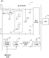
- Block diagram of the power conversion device Circuit diagram of the discharge control circuit according to the first embodiment The figure which shows the flow of the current in the discharge control circuit which concerns on Embodiment 1. It is a timing chart which shows the discharge operation of the power conversion apparatus which concerns on Embodiment 1, (a) shows the state of a contactor for a power source, (b) shows the state of a relay, (c) is the voltage of an internal coil. (D) is a timing chart showing the state of the discharge contactor. Circuit diagram of the discharge control circuit according to the second embodiment The figure which shows the current flow in the discharge control circuit which concerns on Embodiment 2.
- the power conversion device 1 according to the first embodiment will be described by taking as an example a power conversion device mounted on a vehicle, specifically, an auxiliary power supply device mounted on a DC feeder type electric railway vehicle. Specifically, the power conversion device 1 converts the DC power supplied from the main power supply via the positive input terminal 1a into the power for supplying the load 51, for example, three-phase AC power, and converts the three-phase AC power into three-phase AC power. It is supplied to the load 51.
- the discharge circuit 12 for discharging the filter capacitor FC1 includes a discharge contactor MC2.
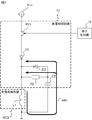
- the power conversion device 1 includes a positive electrode input terminal 1a connected to a main power supply, a grounded negative electrode input terminal 1b, a power supply contactor MC1 having one end connected to the positive electrode input terminal 1a, and a power supply contactor at one end. It includes a filter capacitor FC1 which is connected to the other end of the MC1 and the other end is connected to the negative electrode input terminal 1b.
- the power conversion device 1 further converts the DC power supplied via the primary terminal 11a into three-phase AC power, and supplies the power conversion unit 11 to the load 51, and a discharge circuit connected in parallel to the filter capacitor FC1. 12 and.
- the power conversion device 1 further controls a contactor control unit 13 that controls the power supply contactor MC1, a switching control unit 14 that controls the power conversion unit 11, and a discharge contactor MC2 included in the discharge circuit 12. It includes a discharge control circuit 15 and an element control unit 16 that controls a relay RY1 described later, which is a switching element included in the discharge control circuit 15.
- the positive electrode input terminal 1a is connected to a pantograph that obtains power from a substation via a main power source, for example, an overhead wire.
- the negative electrode input terminal 1b is grounded via, for example, a grounding brush, wheels, and rails.
- the power contactor MC1 is a DC magnetic contactor and is controlled by the contactor control unit 13.
- the contactor control unit 13 When the contactor control unit 13 turns on the power contactor MC1, one end and the other end of the power supply contactor MC1 are connected to each other. As a result, the power conversion unit 11 and the filter capacitor FC1 are electrically connected to the main power supply and receive power from the main power supply. Further, when the contactor control unit 13 opens the power supply contactor MC1, one end and the other end of the power supply contactor MC1 are insulated. As a result, the power conversion unit 11 and the filter capacitor FC1 are electrically disconnected from the main power supply, and cannot receive power from the main power supply.
- the filter capacitor FC1 is connected between the primary terminals 11a and 11b of the power conversion unit 11 and is charged by the power supplied from the main power supply. Specifically, one end of the filter capacitor FC1 is connected to a connection point between the power contactor MC1 and the primary terminal 11a of the power conversion unit 11. The other end of the filter capacitor FC1 is connected to the connection point between the negative electrode input terminal 1b and the primary terminal 11b of the power conversion unit 11.
- the power conversion unit 11 converts the DC power supplied via the primary terminal 11a into three-phase AC power, and supplies the three-phase AC power to the load 51 connected to each secondary terminal.
- the power conversion unit 11 has a plurality of high-speed switching elements capable of high-speed switching, for example, an IGBT (Insulated Gate Bipolar Transistor).
- IGBT Insulated Gate Bipolar Transistor
- a plurality of high-speed switching elements are controlled by the switching control unit 14 and repeatedly turned on and off, so that the power conversion unit 11 converts DC power into three-phase AC power and converts the three-phase AC power into the load 51 as described above.
- the load 51 is an arbitrary in-vehicle device such as a lighting device and an air conditioner.
- the discharge circuit 12 is connected in parallel with the filter capacitor FC1. Specifically, one end of the discharge circuit 12 is connected to the other end of the power contactor MC1 and the connection point of the primary terminal 11a of the power conversion unit 11. The other end of the discharge circuit 12 is connected to the connection point between the negative electrode input terminal 1b and the primary terminal 11b of the power conversion unit 11.
- the discharge circuit 12 includes a capacitor discharge resistor R1 and a discharge contactor MC2 connected in series with the capacitor discharge resistor R1. Each part of the discharge circuit 12 will be described.
- One end of the capacitor discharge resistor R1 is connected to the connection point between the other end of the power contactor MC1 and the primary terminal 11a of the power conversion unit 11.
- the resistance value of the capacitor discharge resistor R1 is arbitrary as long as the filter capacitor FC1 can be discharged in a predetermined time.
- the discharge contactor MC2 is a DC electromagnetic contactor and is controlled by the discharge control circuit 15.
- the discharge control circuit 15 When the discharge control circuit 15 turns on the discharge contactor MC2, one end and the other end of the discharge contactor MC2 are connected to each other. As a result, the filter capacitor FC1 and the capacitor discharge resistor R1 are electrically connected. Then, the filter capacitor FC1 is discharged by the current flowing from the filter capacitor FC1 to the capacitor discharge resistor R1. When the discharge control circuit 15 opens the discharge contactor MC2, one end and the other end of the discharge contactor MC2 are insulated. In this case, since the filter capacitor FC1 and the capacitor discharge resistor R1 are not electrically connected, the filter capacitor FC1 is not discharged by the capacitor discharge resistor R1.
- the discharge contactor MC2 has an internal coil L1 and is in a state of being turned on when the internal coil L1 is discharged, and in a state of being opened when the internal coil L1 is energized.
- a B-contact type DC electromagnetic contactor is used.
- One end of the internal coil L1 will be described in detail later, but is electrically connected to or electrically disconnected from the control power supply Vcc by the discharge control circuit 15.
- the control power supply Vcc is a power supply independent of the main power supply, and is, for example, a battery mounted on an electric railway vehicle.
- the other end of the internal coil L1 is grounded.
- the contactor control unit 13 shown in FIG. 1 is supplied with an open / close instruction signal instructing to turn on or open the power contactor MC1 from a driver's cab (not shown).
- the contactor control unit 13 turns on or opens the power contactor MC1 according to the open / close instruction signal.
- the contactor control unit 13 sends a contactor control signal S1 instructing the contactor MC1 for power supply to turn on or open, and controls the contactor MC1 for power supply.
- the switching control unit 14 acquires a measured value of the voltage between terminals of the filter capacitor FC1 from a voltage measuring unit (not shown). Then, after the power contactor MC1 is turned on and the filter capacitor FC1 is charged, the switching control unit 14 starts on / off control of the high-speed switching element of the power conversion unit 11. Specifically, after the measured value of the inter-terminal voltage of the filter capacitor FC1 reaches the charging voltage, the switching control unit 14 sends a switching control signal S2 instructing each of the plurality of high-speed switching elements to repeat on / off. As a result, the power conversion unit 11 converts the DC power supplied from the main power source into the three-phase AC power, and supplies the three-phase AC power to the load 51.
- the discharge control circuit 15 controls the discharge contactor MC2 by discharging or energizing the internal coil L1 of the discharge contactor MC2.
- the discharge control circuit 15 includes a relay RY1 which is a switching element, a coil discharge resistor R2 connected in series, and a control capacitor C2.
- the discharge control circuit 15 includes diodes D1 and D2 in order to discharge the internal coil L1 while preventing the current from flowing back to the control power supply Vcc when the relay RY1 is turned off. Is preferable.
- the relay RY1 is connected to the control power supply Vcc.
- the other end of the relay RY1 is connected to one end of the internal coil L1 via the diode D1.
- the relay RY1 electrically connects the internal coil L1 to the control power supply Vcc or electrically disconnects it from the control power supply Vcc.
- the relay RY1 is controlled by the element control unit 16.
- the anode of the diode D1 is connected to the other end of the relay RY1. Further, the cathode of the diode D1 is connected to one end of the internal coil L1. The diode D1 suppresses the backflow of current to the control power supply Vcc.
- the anode of the diode D2 is connected to the connection point between the coil discharge resistor R2 and the control capacitor C2. Further, the cathode of the diode D2 is connected to one end of the internal coil L1.
- the diode D2 makes it possible to discharge the internal coil L1 by the coil discharge resistor R2 and the control capacitor C2 by forming an electric circuit from the other end to one end of the coil discharge resistor R2, which will be described later.
- the resistance value of the coil discharge resistor R2 is an arbitrary resistance value capable of discharging the internal coil L1 at a desired time.
- the desired time may be determined, for example, according to a target value of the time required for restarting the power conversion device 1.
- the other end of the control capacitor C2 is connected to the other end of the internal coil L1.
- the discharge control circuit 15 having the above configuration, when the relay RY1 is turned on by the element control unit 16, the internal coil L1 is electrically connected to the control power supply Vcc. Since the internal coil L1 is energized, the discharge contactor MC2 is in an open state. When the relay RY1 is turned off by the element control unit 16, the internal coil L1 is electrically disconnected from the control power supply Vcc. As a result, as shown by the arrow AR1 in FIG. 3, a current flows from the internal coil L1 to the coil discharge resistor R2 and the diode D2 via the control capacitor C2, and the internal coil L1 is discharged. When the internal coil L1 is discharged, the discharge contactor MC2 is in the charged state.
- the element control unit 16 shown in FIG. 1 is supplied with an open / close instruction signal instructing to turn on or open the power contactor MC1.
- the element control unit 16 turns on or off the relay RY1 of the discharge control circuit 15 depending on whether the power contactor MC1 is turned on or open. Specifically, the element control unit 16 keeps the relay RY1 on while the power contactor MC1 is turned on. Further, the element control unit 16 immediately turns off the relay RY1 when the power contactor MC1 is released from the turned-on state.
- the element control unit 16 acquires the measured value of the voltage between the terminals of the filter capacitor FC1 from the voltage measurement unit.
- the element control unit 16 turns on the relay RY1.
- the discharge contactor MC2 is opened after the discharge of the filter capacitor FC1 is completed.
- an open / close instruction signal is supplied from the driver's cab to each of the contactor control unit 13 and the element control unit 16.
- an open / close instruction signal for instructing the power supply contactor MC1 to be turned on is supplied from the driver's cab to each of the contactor control unit 13 and the element control unit 16.
- the contactor control unit 13 When the contactor control unit 13 is supplied with an open / close instruction signal instructing the power supply contactor MC1 to be turned on, the contactor control unit 13 outputs a contactor control signal S1 instructing the power supply contactor MC1 to be turned on. As a result, the power contactor MC1 is turned on, the power acquired by the pantograph from the substation via the overhead wire is supplied to the filter capacitor FC1 via the power supply contactor MC1, and charging of the filter capacitor FC1 is started. NS.
- the element control unit 16 keeps the relay RY1 on when an open / close instruction signal for instructing the power supply contactor MC1 to be turned on is supplied. As a result, the internal coil L1 is energized, and the discharge contactor MC2 is maintained in an open state.
- the switching control unit 14 starts on / off control of the high-speed switching element of the power conversion unit 11.
- the high-speed switching element controlled by the switching control unit 14 repeats on / off.
- the power conversion unit 11 converts the DC power supplied through the filter capacitor FC1 into three-phase AC power, and supplies the three-phase AC power to the load 51.
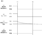
- the operation of the power conversion device 1 when the operation of the electric railway vehicle is stopped will be described with reference to FIG.
- the power conversion unit 11 is stopped, the power contactor MC1 is opened, and the discharge contactor MC2 is turned on.
- the operation of the power conversion device 1 will be described by taking as an example a case where the ascending / descending switch is operated at time T1 and the pantograph descends and is separated from the overhead wire.
- a signal instructing stop is sent to the switching control unit 14 in conjunction with the operation of the ascending / descending switch. Then, the switching control unit 14 turns off the plurality of high-speed switching elements included in the power conversion unit 11 and stops the power conversion unit 11.
- an open / close instruction signal for instructing the opening of the power contactor MC1 is supplied from the driver's cab to each of the contactor control unit 13 and the element control unit 16.
- the contactor control unit 13 to which the opening / closing instruction signal instructing the opening of the power contactor MC1 is supplied outputs the contactor control signal S1 instructing the opening of the power contactor MC1.
- the power contactor MC1 is opened, and the power conversion unit 11 and the filter capacitor FC1 are electrically disconnected from the pantograph, that is, the main power supply.
- the element control unit 16 to which the open / close instruction signal for instructing the opening of the power contactor MC1 is supplied turns off the relay RY1.
- the relay RY1 is turned off at the time T1.
- the internal coil L1 is electrically disconnected from the control power supply Vcc, so that the voltage of the internal coil L1 drops from the energized voltage VL1 at time T1 as shown in FIG. 4C. start.
- the capacitor discharge resistor R1 When the discharge contactor MC2 is turned on, the capacitor discharge resistor R1 is electrically connected to the filter capacitor FC1, so that the filter capacitor FC1 is discharged.
- the time from time T1 to time T2 is determined according to the time constant obtained by multiplying the result of adding the coil resistance value of the internal coil L1 to the resistance value of the capacitor discharge resistance R1 by the capacitance of the filter capacitor FC1. .. Further, the release voltage VL2 is preferably less than a value obtained by multiplying the voltage VL1 at the time of energization by 1 / e. Note that e is a natural logarithm.
- the element control unit 16 turns on the relay RY1. Specifically, when the measured value of the voltage between the terminals of the filter capacitor FC1 becomes equal to or less than the threshold voltage, the element control unit 16 turns on the relay RY1. As a result, the internal coil L1 is energized and the discharge contactor MC2 is opened.
- the discharge contactor MC2 is turned on after the power supply contactor MC1 is opened. Therefore, the power supply contactor MC1 and the discharge contactor MC2 are not turned on at the same time. That is, the short-circuit current is suppressed from flowing through the capacitor discharge resistor R1.
- the short-circuit current is suppressed from flowing through the capacitor discharge resistor R1 since the short-circuit current is suppressed from flowing through the capacitor discharge resistor R1, it is not necessary to increase the capacitance of the capacitor discharge resistor R1 in order to prevent the short-circuit current from flowing through the capacitor discharge resistor R1 and causing burning. In other words, it is suppressed that the capacitor discharge resistor R1 becomes larger as the capacitance of the capacitor discharge resistor R1 increases. As a result, the increase in size of the power conversion device 1 is suppressed.
- the configuration of the discharge control circuit 15 is not limited to the example of the first embodiment. Specifically, the configuration of the discharge control circuit 15 is arbitrary as long as the discharge contactor MC2 can be turned on after the power supply contactor MC1 is opened.
- the configuration of the power conversion device 1 according to the second embodiment is the same as that of the first embodiment.
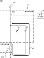
- the discharge control circuit 15 included in the power conversion device 1 according to the second embodiment is a diode D3 connected in parallel to the relay RY1 which is a switching element and the internal coil L1 of the discharge contactor MC2.
- the power conversion device 1 preferably includes a surge absorbing element B1 connected in parallel to the internal coil L1 of the discharge contactor MC2.
- One end of the relay RY1 is connected to the control power supply Vcc.
- the other end of the relay RY1 is connected to one end of the internal coil L1.
- the structure and operation of the relay RY1 are the same as those in the first embodiment.
- the diode D3 is connected in parallel to the internal coil L1. Specifically, the anode of the diode D3 is connected to the other end of the internal coil L1. The cathode of the diode D3 is connected to the connection point between the relay RY1 and the internal coil L1.
- the surge absorbing element B1 is connected in parallel to the internal coil L1.
- the surge absorbing element B1 is a varistor, and suppresses the application of an overvoltage to an element connected in parallel, that is, a diode D3, when the internal coil L1 is discharged.
- the discharge control circuit 15 having the above configuration, when the relay RY1 is turned on by the element control unit 16, the internal coil L1 is electrically connected to the control power supply Vcc. Since the internal coil L1 is energized, the discharge contactor MC2 is in an open state. When the relay RY1 is turned off by the element control unit 16, the internal coil L1 is electrically disconnected from the control power supply Vcc. As a result, as shown by the arrow AR2 in FIG. 6, a current flows from the internal coil L1 to the diode D3, and the internal coil L1 is discharged. When the internal coil L1 is discharged, the discharge contactor MC2 is in the charged state.
- An opening / closing instruction signal is supplied to the element control unit 16 of the power conversion device 1 according to the second embodiment as in the first embodiment. Further, the element control unit 16 turns the relay RY1 on or off depending on whether the power contactor MC1 is turned on or open.
- the element control unit 16 included in the power conversion device 1 according to the second embodiment has a timing at which the relay RY1 is turned off different from that of the element control unit 16 included in the power conversion device 1 according to the first embodiment.
- the element control unit 16 keeps the relay RY1 on while the power contactor MC1 is turned on. Further, when the element control unit 16 is released from the state in which the power contactor MC1 is turned on, the relay RY1 is turned off after a lapse of a predetermined time after the power supply contactor MC1 is opened.
- the specified time is longer than the time required from the instruction to open the power supply contactor MC1 to the actual opening of the power supply contactor MC1, and the discharge contactor MC2 is turned on. It can be determined according to the design value of the time required.
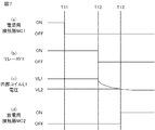
- the operation of the power conversion device 1 when the operation of the electric railway vehicle is stopped will be described with reference to FIG. 7.
- the power conversion unit 11 is stopped, the power contactor MC1 is opened, and the discharge contactor MC2 is turned on.
- the operation of the power conversion device 1 will be described by taking as an example a case where the ascending / descending switch is operated at time T11 and the pantograph descends and is separated from the overhead wire.
- a signal instructing stop is sent to the switching control unit 14 in conjunction with the operation of the ascending / descending switch. Then, the switching control unit 14 turns off the plurality of high-speed switching elements included in the power conversion unit 11 and stops the power conversion unit 11.
- an open / close instruction signal for instructing the opening of the power contactor MC1 is supplied from the driver's cab to each of the contactor control unit 13 and the element control unit 16.
- the contactor control unit 13 to which the opening / closing instruction signal instructing the opening of the power contactor MC1 is supplied outputs the contactor control signal S1 instructing the opening of the power contactor MC1.
- the power contactor MC1 is opened, and the power conversion unit 11 and the filter capacitor FC1 are electrically disconnected from the pantograph, that is, the main power supply.
- the element control unit 16 to which the open / close instruction signal for instructing the opening of the power contactor MC1 is supplied turns off the relay RY1 at the time T12 when the time T12 determined from the time T11 has elapsed.
- the relay RY1 is turned off at the time T12.
- the internal coil L1 is electrically disconnected from the control power supply Vcc, so that the voltage of the internal coil L1 drops from the energized voltage VL1 at time T12 as shown in FIG. 7 (c). start.
- the capacitor discharge resistor R1 When the discharge contactor MC2 is turned on, the capacitor discharge resistor R1 is electrically connected to the filter capacitor FC1, so that the filter capacitor FC1 is discharged.
- the time from the time T12 to the time T13 is determined according to the coil resistance value of the internal coil L1. In other words, the time from time T12 to time T13 is shorter than the time from time T1 to time T2 in the first embodiment.
- the release voltage VL2 is preferably less than a value obtained by multiplying the voltage VL1 at the time of energization by 1 / e.
- the element control unit 16 turns on the relay RY1. Specifically, when the measured value of the voltage between the terminals of the filter capacitor FC1 becomes equal to or less than the threshold voltage, the element control unit 16 turns on the relay RY1. As a result, the internal coil L1 is energized and the discharge contactor MC2 is opened.
- the discharge contactor MC2 is turned on after the power supply contactor MC1 is opened. Therefore, the power supply contactor MC1 and the discharge contactor MC2 are not turned on at the same time. That is, the short-circuit current is suppressed from flowing through the capacitor discharge resistor R1.
- the discharge control circuit 15 included in the power conversion device 1 according to the second embodiment has a control capacitor C2, a coil discharge resistor R2, and a coil discharge resistor R2 like the discharge control circuit 15 included in the power conversion device 1 according to the first embodiment. It is not necessary to provide the diodes D1 and D2. Therefore, the power conversion device 1 according to the second embodiment can be made smaller than the power conversion device 1 according to the first embodiment.
- FIG. 8 shows an example of another circuit configuration of the power conversion device 1.
- the power conversion device 2 shown in FIG. 8 includes a charging contactor MC3 and a charging resistor R3 in addition to the configuration of the power conversion device 1 shown in FIG.
- the charging contactor MC3 and the charging resistor R3 are connected in series. Further, the charging contactor MC3 and the charging resistor R3 connected in series are connected in parallel to the power supply contactor MC1. Specifically, one end of the charging contactor MC3 is connected to a connection point between one end of the power supply contactor MC1 and the positive electrode input terminal 1a. The other end of the charging contactor MC3 is connected to one end of the charging resistor R3. The other end of the charging resistor R3 is connected to the connection point between the other end of the power contactor MC1 and the primary terminal 11a of the power conversion unit 11.
- the charging contactor MC3 is controlled by the contactor control unit 13. Specifically, the contactor control unit 13 outputs the contactor control signal S1 instructing the charging contactor MC3 to turn on when the opening / closing instruction signal instructing to turn on the power contactor MC1 is supplied. As a result, the charging contactor MC3 is turned on, power is supplied from the main power supply to the filter capacitor FC1 via the charging contactor MC3 and the charging resistor R3, and charging of the filter capacitor FC1 is started.
- the contactor control unit 13 acquires a measured value of the voltage between terminals of the filter capacitor FC1 from a voltage measuring unit (not shown). When the measured value of the voltage between the terminals of the filter capacitor FC1 reaches the charging voltage, the contactor control unit 13 included in the power conversion device 2 outputs a contactor control signal S1 instructing the power supply contactor MC1 to be turned on. As a result, the power supply contactor MC1 is turned on, and power is supplied from the main power supply to the filter capacitor FC1 via the power supply contactor MC1.
- the contactor control unit 13 outputs a contactor control signal S1 instructing the power contactor MC1 to be turned on, and then outputs a contactor control signal S1 for opening the charging contactor MC3.
- the charging resistor R3 is electrically disconnected from the main power source. As described above, by turning on the charging contactor MC3 and then turning on the power supply contactor MC1, the inrush current is suppressed from flowing through the filter capacitor FC1.
- FIG. 9 shows an example of another circuit configuration of the power conversion device 1.
- the power conversion device 3 shown in FIG. 9 includes a charging contactor MC4 and a charging resistor R3 in addition to the configuration of the power conversion device 1 according to the first embodiment shown in FIG.
- the charging contactor MC4 is connected to the positive electrode input terminal 1a and one end of the power supply contactor MC1.
- One end of the charging resistor R3 is connected to a connection point between the charging contactor MC4 and the power supply contactor MC1.
- the other end of the charging resistor R3 is connected to the connection point between the power contactor MC1 and the primary terminal 11a of the power conversion unit 11.
- the charging contactor MC4 is controlled by the contactor control unit 13. Specifically, the contactor control unit 13 outputs the contactor control signal S1 instructing the charging contactor MC4 to turn on when the opening / closing instruction signal instructing to turn on the power contactor MC1 is supplied. As a result, the charging contactor MC4 is turned on, power is supplied from the main power supply to the filter capacitor FC1 via the charging contactor MC4 and the charging resistor R3, and charging of the filter capacitor FC1 is started.
- the contactor control unit 13 acquires a measured value of the voltage between terminals of the filter capacitor FC1 from a voltage measuring unit (not shown). When the measured value of the voltage between the terminals of the filter capacitor FC1 reaches the threshold voltage, the contactor control unit 13 included in the power conversion device 3 outputs the contactor control signal S1 instructing the power supply contactor MC1 to be turned on. As a result, the power supply contactor MC1 is turned on, and power is supplied from the main power supply to the filter capacitor FC1 via the charging contactor MC4 and the power supply contactor MC1.
- the element control unit 16 may acquire a state signal indicating whether the power contactor MC1 is turned on or off from the power supply contactor MC1. In this case, when the element control unit 16 detects that the power contactor MC1 has been released from the turned-on state based on the state signal acquired from the power supply contactor MC1, the relay RY1 is turned off. The discharge contactor MC2 may be turned on.
- the power conversion device 1-3 may include a filter reactor provided between the other end of the power contactor MC1 and the primary terminal 11a of the power conversion unit 11. By providing the filter reactor, the input current of the power conversion unit 11 can be smoothed.
- the power conversion unit 11 is an arbitrary power conversion circuit.
- a DC (Direct Current) -DC converter can be used as the power conversion unit 11.
- the discharge control circuit 15 may include an arbitrary switching element such as an IGBT, MOSFET (Metal-Oxide-Semiconductor Field-Effect Transistor), or thyristor instead of the relay RY1. Further, the discharge control circuit 15 included in the power conversion device 1 according to the second embodiment may have the diode D1 as in the first embodiment.
- an arbitrary switching element such as an IGBT, MOSFET (Metal-Oxide-Semiconductor Field-Effect Transistor), or thyristor instead of the relay RY1.
- MOSFET Metal-Oxide-Semiconductor Field-Effect Transistor
- the power conversion device 1-3 is not limited to the auxiliary power supply device, but is an arbitrary power conversion device provided with the filter capacitor FC1.
- the power conversion device 1-3 can be mounted on any vehicle, any device, etc. that can supply power to the power conversion device 1-3.
- the power conversion device 1-3 can be mounted on an AC feeder type electric railway vehicle.
- a transformer whose primary terminal is connected to the pantograph and a converter which is connected to the secondary terminal of the transformer and converts AC power into DC power are provided, and the output of the converter is supplied to the power converter 1-3. Just do it.
- the power conversion device 1-3 may be mounted on an electric railway vehicle that acquires electric power via the third rail.
- 1,2,3 Power converter 1a Positive input terminal, 1b Negative input terminal, 11 Power converter, 11a, 11b Primary terminal, 12 Discharge circuit, 13 Contact control unit, 14 Switching control unit, 15 Discharge control circuit, 16 element control unit, 51 load, AR1, AR2 arrow, B1 surge absorption element, C2 control capacitor, D1, D2, D3 diode, FC1 filter capacitor, L1 internal coil, MC1 power supply contactor, MC2 discharge contactor, MC3, MC4 Charging contact, R1 Capacitor discharge resistance, R2 Coil discharge resistance, R3 Charging resistance, RY1 relay, S1 Contact control signal, S2 Switching control signal, Vcc control power supply.
Landscapes
- Engineering & Computer Science (AREA)
- Power Engineering (AREA)
- Inverter Devices (AREA)
- Electric Propulsion And Braking For Vehicles (AREA)
Priority Applications (4)
| Application Number | Priority Date | Filing Date | Title |
|---|---|---|---|
| US17/905,945 US12231057B2 (en) | 2020-03-26 | 2020-03-26 | Power conversion device for suppressing flow of short-circuit current to discharging resistor |
| JP2022510262A JP7123284B2 (ja) | 2020-03-26 | 2020-03-26 | 電力変換装置 |
| DE112020006976.1T DE112020006976T5 (de) | 2020-03-26 | 2020-03-26 | Leistungswandlervorrichtung |
| PCT/JP2020/013687 WO2021192145A1 (ja) | 2020-03-26 | 2020-03-26 | 電力変換装置 |
Applications Claiming Priority (1)
| Application Number | Priority Date | Filing Date | Title |
|---|---|---|---|
| PCT/JP2020/013687 WO2021192145A1 (ja) | 2020-03-26 | 2020-03-26 | 電力変換装置 |
Publications (1)
| Publication Number | Publication Date |
|---|---|
| WO2021192145A1 true WO2021192145A1 (ja) | 2021-09-30 |
Family
ID=77890041
Family Applications (1)
| Application Number | Title | Priority Date | Filing Date |
|---|---|---|---|
| PCT/JP2020/013687 Ceased WO2021192145A1 (ja) | 2020-03-26 | 2020-03-26 | 電力変換装置 |
Country Status (4)
| Country | Link |
|---|---|
| US (1) | US12231057B2 (enExample) |
| JP (1) | JP7123284B2 (enExample) |
| DE (1) | DE112020006976T5 (enExample) |
| WO (1) | WO2021192145A1 (enExample) |
Cited By (2)
| Publication number | Priority date | Publication date | Assignee | Title |
|---|---|---|---|---|
| WO2023117890A1 (en) * | 2021-12-20 | 2023-06-29 | GE Grid GmbH | Systems and methods for discharging energy storage devices |
| WO2024012744A1 (de) * | 2022-07-14 | 2024-01-18 | Robert Bosch Gmbh | Vorrichtung und verfahren zur steuerung der entladung eines zwischenkreiskondensators |
Citations (4)
| Publication number | Priority date | Publication date | Assignee | Title |
|---|---|---|---|---|
| JP2003052179A (ja) * | 2001-08-03 | 2003-02-21 | Toshiba Corp | 電力変換装置 |
| JP2005073399A (ja) * | 2003-08-25 | 2005-03-17 | Toyota Motor Corp | 電源装置およびそれを搭載した自動車 |
| JP2009004365A (ja) * | 2007-05-18 | 2009-01-08 | Panasonic Corp | リレー駆動回路、及びそれを用いた電池パック |
| JP2009143506A (ja) * | 2007-12-18 | 2009-07-02 | Honda Motor Co Ltd | コンタクタ制御システム |
Family Cites Families (11)
| Publication number | Priority date | Publication date | Assignee | Title |
|---|---|---|---|---|
| JPH08251701A (ja) * | 1995-03-07 | 1996-09-27 | Toshiba Corp | 車両用電源装置 |
| JP3560766B2 (ja) * | 1997-05-13 | 2004-09-02 | 株式会社東芝 | 電力変換装置 |
| JP2010041806A (ja) | 2008-08-04 | 2010-02-18 | Toshiba Corp | 電気車用電源装置 |
| US8115457B2 (en) * | 2009-07-31 | 2012-02-14 | Power Integrations, Inc. | Method and apparatus for implementing a power converter input terminal voltage discharge circuit |
| CN102545195B (zh) | 2012-03-16 | 2014-11-05 | 成都芯源系统有限公司 | Emi滤波电容器放电电路及放电方法 |
| CN204131101U (zh) * | 2014-07-29 | 2015-01-28 | 天津安耐吉燃气技术有限公司 | 一种接触器保护装置 |
| CN105322511A (zh) * | 2014-07-29 | 2016-02-10 | 天津安耐吉燃气技术有限公司 | 接触器保护装置 |
| JP7241966B2 (ja) * | 2020-03-26 | 2023-03-17 | 三菱電機株式会社 | 電力変換装置 |
| CN114087226B (zh) * | 2021-11-30 | 2024-03-19 | 上海氢蓝新能源科技有限公司 | 氢燃料电池系统空压机控制系统、方法及存储介质 |
| DE112022006926T5 (de) * | 2022-03-29 | 2025-01-09 | Mitsubishi Electric Corporation | Leistungswandlervorrichtung |
| CN218648723U (zh) * | 2022-10-09 | 2023-03-17 | 深圳市高斯宝电气技术有限公司 | 一种开关电源测试装置的母线电容放电电路 |
-
2020
- 2020-03-26 WO PCT/JP2020/013687 patent/WO2021192145A1/ja not_active Ceased
- 2020-03-26 US US17/905,945 patent/US12231057B2/en active Active
- 2020-03-26 DE DE112020006976.1T patent/DE112020006976T5/de active Pending
- 2020-03-26 JP JP2022510262A patent/JP7123284B2/ja active Active
Patent Citations (4)
| Publication number | Priority date | Publication date | Assignee | Title |
|---|---|---|---|---|
| JP2003052179A (ja) * | 2001-08-03 | 2003-02-21 | Toshiba Corp | 電力変換装置 |
| JP2005073399A (ja) * | 2003-08-25 | 2005-03-17 | Toyota Motor Corp | 電源装置およびそれを搭載した自動車 |
| JP2009004365A (ja) * | 2007-05-18 | 2009-01-08 | Panasonic Corp | リレー駆動回路、及びそれを用いた電池パック |
| JP2009143506A (ja) * | 2007-12-18 | 2009-07-02 | Honda Motor Co Ltd | コンタクタ制御システム |
Cited By (2)
| Publication number | Priority date | Publication date | Assignee | Title |
|---|---|---|---|---|
| WO2023117890A1 (en) * | 2021-12-20 | 2023-06-29 | GE Grid GmbH | Systems and methods for discharging energy storage devices |
| WO2024012744A1 (de) * | 2022-07-14 | 2024-01-18 | Robert Bosch Gmbh | Vorrichtung und verfahren zur steuerung der entladung eines zwischenkreiskondensators |
Also Published As
| Publication number | Publication date |
|---|---|
| US20230096893A1 (en) | 2023-03-30 |
| DE112020006976T5 (de) | 2023-01-12 |
| US12231057B2 (en) | 2025-02-18 |
| JP7123284B2 (ja) | 2022-08-22 |
| JPWO2021192145A1 (enExample) | 2021-09-30 |
Similar Documents
| Publication | Publication Date | Title |
|---|---|---|
| CN102856985B (zh) | 对电动装置进行充电或放电的设备 | |
| US20160105092A1 (en) | Discharge control device | |
| JP2017225279A (ja) | 電力変換システム | |
| RU2703190C1 (ru) | Выключатель постоянного напряжения | |
| CN217498548U (zh) | 电梯非隔离安全抱闸电源及电梯设备 | |
| JP6324631B2 (ja) | 鉄道車両用制御装置 | |
| JP7123284B2 (ja) | 電力変換装置 | |
| JP2016059084A (ja) | プリチャージ回路 | |
| TWI622244B (zh) | 電力轉換系統 | |
| CN108390377A (zh) | 一种岸基供电系统及减小励磁涌流的方法 | |
| JP2018107987A (ja) | 鉄道車両用回路システム | |
| KR102749925B1 (ko) | 프리 차져 | |
| JP2004135478A (ja) | 昇降圧兼用dc−dcコンバータ | |
| WO2011067974A1 (ja) | Pfcコンバータ | |
| US20240339948A1 (en) | Method of operating a power supply circuit in an inverter for driving an electrical machine, computing unit, power supply circuit of an inverter and inverter | |
| JP4003255B2 (ja) | 車両用電気機器装置の保護装置 | |
| KR102639091B1 (ko) | 프리 차져 | |
| JP2017147887A (ja) | 電源システム | |
| JP2015050825A (ja) | 放電制御装置 | |
| JP7650736B2 (ja) | バッテリ充電装置、保護装置、及び保護方法 | |
| CN119968765A (zh) | 充电器和用于操作充电器的方法 | |
| JP2001520800A (ja) | 自動車のヘッドライト用放電ランプの電源装置 | |
| CN113632380B (zh) | 电力电子设备和用于向功率半导体开关的驱动电路供应电压的方法 | |
| JP4000621B2 (ja) | 車両用負荷駆動装置 | |
| JPH0884479A (ja) | スイッチング回路の安全装置 |
Legal Events
| Date | Code | Title | Description |
|---|---|---|---|
| 121 | Ep: the epo has been informed by wipo that ep was designated in this application |
Ref document number: 20926479 Country of ref document: EP Kind code of ref document: A1 |
|
| ENP | Entry into the national phase |
Ref document number: 2022510262 Country of ref document: JP Kind code of ref document: A |
|
| 122 | Ep: pct application non-entry in european phase |
Ref document number: 20926479 Country of ref document: EP Kind code of ref document: A1 |