WO2021192145A1 - Power conversion device - Google Patents
Power conversion device Download PDFInfo
- Publication number
- WO2021192145A1 WO2021192145A1 PCT/JP2020/013687 JP2020013687W WO2021192145A1 WO 2021192145 A1 WO2021192145 A1 WO 2021192145A1 JP 2020013687 W JP2020013687 W JP 2020013687W WO 2021192145 A1 WO2021192145 A1 WO 2021192145A1
- Authority
- WO
- WIPO (PCT)
- Prior art keywords
- contactor
- power
- discharge
- power supply
- power conversion
- Prior art date
Links
Images


Classifications
-
- H—ELECTRICITY
- H02—GENERATION; CONVERSION OR DISTRIBUTION OF ELECTRIC POWER
- H02M—APPARATUS FOR CONVERSION BETWEEN AC AND AC, BETWEEN AC AND DC, OR BETWEEN DC AND DC, AND FOR USE WITH MAINS OR SIMILAR POWER SUPPLY SYSTEMS; CONVERSION OF DC OR AC INPUT POWER INTO SURGE OUTPUT POWER; CONTROL OR REGULATION THEREOF
- H02M1/00—Details of apparatus for conversion
- H02M1/32—Means for protecting converters other than automatic disconnection
- H02M1/322—Means for rapidly discharging a capacitor of the converter for protecting electrical components or for preventing electrical shock
-
- H—ELECTRICITY
- H02—GENERATION; CONVERSION OR DISTRIBUTION OF ELECTRIC POWER
- H02M—APPARATUS FOR CONVERSION BETWEEN AC AND AC, BETWEEN AC AND DC, OR BETWEEN DC AND DC, AND FOR USE WITH MAINS OR SIMILAR POWER SUPPLY SYSTEMS; CONVERSION OF DC OR AC INPUT POWER INTO SURGE OUTPUT POWER; CONTROL OR REGULATION THEREOF
- H02M7/00—Conversion of ac power input into dc power output; Conversion of dc power input into ac power output
- H02M7/42—Conversion of dc power input into ac power output without possibility of reversal
- H02M7/44—Conversion of dc power input into ac power output without possibility of reversal by static converters
-
- H—ELECTRICITY
- H02—GENERATION; CONVERSION OR DISTRIBUTION OF ELECTRIC POWER
- H02J—CIRCUIT ARRANGEMENTS OR SYSTEMS FOR SUPPLYING OR DISTRIBUTING ELECTRIC POWER; SYSTEMS FOR STORING ELECTRIC ENERGY
- H02J7/00—Circuit arrangements for charging or depolarising batteries or for supplying loads from batteries
- H02J7/0063—Circuit arrangements for charging or depolarising batteries or for supplying loads from batteries with circuits adapted for supplying loads from the battery
-
- H—ELECTRICITY
- H02—GENERATION; CONVERSION OR DISTRIBUTION OF ELECTRIC POWER
- H02J—CIRCUIT ARRANGEMENTS OR SYSTEMS FOR SUPPLYING OR DISTRIBUTING ELECTRIC POWER; SYSTEMS FOR STORING ELECTRIC ENERGY
- H02J7/00—Circuit arrangements for charging or depolarising batteries or for supplying loads from batteries
- H02J7/34—Parallel operation in networks using both storage and other dc sources, e.g. providing buffering
- H02J7/345—Parallel operation in networks using both storage and other dc sources, e.g. providing buffering using capacitors as storage or buffering devices
-
- H—ELECTRICITY
- H02—GENERATION; CONVERSION OR DISTRIBUTION OF ELECTRIC POWER
- H02M—APPARATUS FOR CONVERSION BETWEEN AC AND AC, BETWEEN AC AND DC, OR BETWEEN DC AND DC, AND FOR USE WITH MAINS OR SIMILAR POWER SUPPLY SYSTEMS; CONVERSION OF DC OR AC INPUT POWER INTO SURGE OUTPUT POWER; CONTROL OR REGULATION THEREOF
- H02M1/00—Details of apparatus for conversion
- H02M1/08—Circuits specially adapted for the generation of control voltages for semiconductor devices incorporated in static converters
-
- H—ELECTRICITY
- H02—GENERATION; CONVERSION OR DISTRIBUTION OF ELECTRIC POWER
- H02M—APPARATUS FOR CONVERSION BETWEEN AC AND AC, BETWEEN AC AND DC, OR BETWEEN DC AND DC, AND FOR USE WITH MAINS OR SIMILAR POWER SUPPLY SYSTEMS; CONVERSION OF DC OR AC INPUT POWER INTO SURGE OUTPUT POWER; CONTROL OR REGULATION THEREOF
- H02M1/00—Details of apparatus for conversion
- H02M1/12—Arrangements for reducing harmonics from ac input or output
- H02M1/126—Arrangements for reducing harmonics from ac input or output using passive filters
-
- H—ELECTRICITY
- H02—GENERATION; CONVERSION OR DISTRIBUTION OF ELECTRIC POWER
- H02M—APPARATUS FOR CONVERSION BETWEEN AC AND AC, BETWEEN AC AND DC, OR BETWEEN DC AND DC, AND FOR USE WITH MAINS OR SIMILAR POWER SUPPLY SYSTEMS; CONVERSION OF DC OR AC INPUT POWER INTO SURGE OUTPUT POWER; CONTROL OR REGULATION THEREOF
- H02M1/00—Details of apparatus for conversion
- H02M1/36—Means for starting or stopping converters
-
- H—ELECTRICITY
- H02—GENERATION; CONVERSION OR DISTRIBUTION OF ELECTRIC POWER
- H02M—APPARATUS FOR CONVERSION BETWEEN AC AND AC, BETWEEN AC AND DC, OR BETWEEN DC AND DC, AND FOR USE WITH MAINS OR SIMILAR POWER SUPPLY SYSTEMS; CONVERSION OF DC OR AC INPUT POWER INTO SURGE OUTPUT POWER; CONTROL OR REGULATION THEREOF
- H02M7/00—Conversion of ac power input into dc power output; Conversion of dc power input into ac power output
- H02M7/42—Conversion of dc power input into ac power output without possibility of reversal
- H02M7/44—Conversion of dc power input into ac power output without possibility of reversal by static converters
- H02M7/48—Conversion of dc power input into ac power output without possibility of reversal by static converters using discharge tubes with control electrode or semiconductor devices with control electrode
-
- H—ELECTRICITY
- H02—GENERATION; CONVERSION OR DISTRIBUTION OF ELECTRIC POWER
- H02J—CIRCUIT ARRANGEMENTS OR SYSTEMS FOR SUPPLYING OR DISTRIBUTING ELECTRIC POWER; SYSTEMS FOR STORING ELECTRIC ENERGY
- H02J2207/00—Indexing scheme relating to details of circuit arrangements for charging or depolarising batteries or for supplying loads from batteries
- H02J2207/20—Charging or discharging characterised by the power electronics converter
-
- H—ELECTRICITY
- H02—GENERATION; CONVERSION OR DISTRIBUTION OF ELECTRIC POWER
- H02J—CIRCUIT ARRANGEMENTS OR SYSTEMS FOR SUPPLYING OR DISTRIBUTING ELECTRIC POWER; SYSTEMS FOR STORING ELECTRIC ENERGY
- H02J2207/00—Indexing scheme relating to details of circuit arrangements for charging or depolarising batteries or for supplying loads from batteries
- H02J2207/50—Charging of capacitors, supercapacitors, ultra-capacitors or double layer capacitors
-
- Y—GENERAL TAGGING OF NEW TECHNOLOGICAL DEVELOPMENTS; GENERAL TAGGING OF CROSS-SECTIONAL TECHNOLOGIES SPANNING OVER SEVERAL SECTIONS OF THE IPC; TECHNICAL SUBJECTS COVERED BY FORMER USPC CROSS-REFERENCE ART COLLECTIONS [XRACs] AND DIGESTS
- Y02—TECHNOLOGIES OR APPLICATIONS FOR MITIGATION OR ADAPTATION AGAINST CLIMATE CHANGE
- Y02T—CLIMATE CHANGE MITIGATION TECHNOLOGIES RELATED TO TRANSPORTATION
- Y02T10/00—Road transport of goods or passengers
- Y02T10/60—Other road transportation technologies with climate change mitigation effect
- Y02T10/72—Electric energy management in electromobility
Definitions
- This disclosure relates to a power conversion device.
- Some electric railway vehicles are equipped with a power conversion device that converts the power supplied from the substation through the overhead wire into the desired power and supplies the converted power to the load.
- a power conversion device that converts the power supplied from the substation through the overhead wire into the desired power and supplies the converted power to the load.
- An example of this type of power conversion device is disclosed in Patent Document 1.
- the power supply device for an electric vehicle disclosed in Patent Document 1 electrically connects an inverter, a filter capacitor connected between the primary terminals of the inverter, a discharge circuit for discharging the filter capacitor, and the inverter and the filter capacitor to the power supply.
- it is provided with a contactor that is electrically disconnected from the power source.
- the present disclosure has been made in view of the above circumstances, and an object of the present disclosure is to provide a power conversion device that suppresses a short-circuit current flowing through a discharge resistor.
- the power conversion device of the present disclosure includes a filter capacitor, a power conversion unit, a contactor for a power supply, a discharge circuit, and a discharge control circuit.
- the filter capacitor is charged with the power supplied from the main power supply.
- a filter capacitor is connected between the primary terminals of the power converter.
- the power conversion unit converts the power supplied from the main power supply through the filter capacitor into the power to be supplied to the load connected to the secondary terminal, and supplies the converted power to the load.
- the power contactor electrically connects the filter capacitor and the power converter to or disconnects from the main power source.
- the discharge circuit has an internal coil, and has a discharge contactor that is turned on when the internal coil is discharged, and a capacitor discharge resistor connected in series with the discharge contactor.
- the discharge circuit is also connected in parallel with the filter capacitor. In the discharge control circuit, after the contactor for power supply is opened, the contactor for discharge is turned on by discharging the internal coil of the contactor for discharge, and the filter capacitor is discharged.
- the discharge control circuit turns on the discharge contactor by discharging the internal coil of the discharge contactor after the power supply contactor is opened, and discharges the filter capacitor. Since the discharge contactor is turned on after the power supply contactor is opened, the short-circuit current is suppressed from flowing through the discharge resistor.
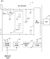
- Block diagram of the power conversion device Circuit diagram of the discharge control circuit according to the first embodiment The figure which shows the flow of the current in the discharge control circuit which concerns on Embodiment 1. It is a timing chart which shows the discharge operation of the power conversion apparatus which concerns on Embodiment 1, (a) shows the state of a contactor for a power source, (b) shows the state of a relay, (c) is the voltage of an internal coil. (D) is a timing chart showing the state of the discharge contactor. Circuit diagram of the discharge control circuit according to the second embodiment The figure which shows the current flow in the discharge control circuit which concerns on Embodiment 2.
- the power conversion device 1 according to the first embodiment will be described by taking as an example a power conversion device mounted on a vehicle, specifically, an auxiliary power supply device mounted on a DC feeder type electric railway vehicle. Specifically, the power conversion device 1 converts the DC power supplied from the main power supply via the positive input terminal 1a into the power for supplying the load 51, for example, three-phase AC power, and converts the three-phase AC power into three-phase AC power. It is supplied to the load 51.
- the discharge circuit 12 for discharging the filter capacitor FC1 includes a discharge contactor MC2.
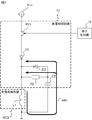
- the power conversion device 1 includes a positive electrode input terminal 1a connected to a main power supply, a grounded negative electrode input terminal 1b, a power supply contactor MC1 having one end connected to the positive electrode input terminal 1a, and a power supply contactor at one end. It includes a filter capacitor FC1 which is connected to the other end of the MC1 and the other end is connected to the negative electrode input terminal 1b.
- the power conversion device 1 further converts the DC power supplied via the primary terminal 11a into three-phase AC power, and supplies the power conversion unit 11 to the load 51, and a discharge circuit connected in parallel to the filter capacitor FC1. 12 and.
- the power conversion device 1 further controls a contactor control unit 13 that controls the power supply contactor MC1, a switching control unit 14 that controls the power conversion unit 11, and a discharge contactor MC2 included in the discharge circuit 12. It includes a discharge control circuit 15 and an element control unit 16 that controls a relay RY1 described later, which is a switching element included in the discharge control circuit 15.
- the positive electrode input terminal 1a is connected to a pantograph that obtains power from a substation via a main power source, for example, an overhead wire.
- the negative electrode input terminal 1b is grounded via, for example, a grounding brush, wheels, and rails.
- the power contactor MC1 is a DC magnetic contactor and is controlled by the contactor control unit 13.
- the contactor control unit 13 When the contactor control unit 13 turns on the power contactor MC1, one end and the other end of the power supply contactor MC1 are connected to each other. As a result, the power conversion unit 11 and the filter capacitor FC1 are electrically connected to the main power supply and receive power from the main power supply. Further, when the contactor control unit 13 opens the power supply contactor MC1, one end and the other end of the power supply contactor MC1 are insulated. As a result, the power conversion unit 11 and the filter capacitor FC1 are electrically disconnected from the main power supply, and cannot receive power from the main power supply.
- the filter capacitor FC1 is connected between the primary terminals 11a and 11b of the power conversion unit 11 and is charged by the power supplied from the main power supply. Specifically, one end of the filter capacitor FC1 is connected to a connection point between the power contactor MC1 and the primary terminal 11a of the power conversion unit 11. The other end of the filter capacitor FC1 is connected to the connection point between the negative electrode input terminal 1b and the primary terminal 11b of the power conversion unit 11.
- the power conversion unit 11 converts the DC power supplied via the primary terminal 11a into three-phase AC power, and supplies the three-phase AC power to the load 51 connected to each secondary terminal.
- the power conversion unit 11 has a plurality of high-speed switching elements capable of high-speed switching, for example, an IGBT (Insulated Gate Bipolar Transistor).
- IGBT Insulated Gate Bipolar Transistor
- a plurality of high-speed switching elements are controlled by the switching control unit 14 and repeatedly turned on and off, so that the power conversion unit 11 converts DC power into three-phase AC power and converts the three-phase AC power into the load 51 as described above.
- the load 51 is an arbitrary in-vehicle device such as a lighting device and an air conditioner.
- the discharge circuit 12 is connected in parallel with the filter capacitor FC1. Specifically, one end of the discharge circuit 12 is connected to the other end of the power contactor MC1 and the connection point of the primary terminal 11a of the power conversion unit 11. The other end of the discharge circuit 12 is connected to the connection point between the negative electrode input terminal 1b and the primary terminal 11b of the power conversion unit 11.
- the discharge circuit 12 includes a capacitor discharge resistor R1 and a discharge contactor MC2 connected in series with the capacitor discharge resistor R1. Each part of the discharge circuit 12 will be described.
- One end of the capacitor discharge resistor R1 is connected to the connection point between the other end of the power contactor MC1 and the primary terminal 11a of the power conversion unit 11.
- the resistance value of the capacitor discharge resistor R1 is arbitrary as long as the filter capacitor FC1 can be discharged in a predetermined time.
- the discharge contactor MC2 is a DC electromagnetic contactor and is controlled by the discharge control circuit 15.
- the discharge control circuit 15 When the discharge control circuit 15 turns on the discharge contactor MC2, one end and the other end of the discharge contactor MC2 are connected to each other. As a result, the filter capacitor FC1 and the capacitor discharge resistor R1 are electrically connected. Then, the filter capacitor FC1 is discharged by the current flowing from the filter capacitor FC1 to the capacitor discharge resistor R1. When the discharge control circuit 15 opens the discharge contactor MC2, one end and the other end of the discharge contactor MC2 are insulated. In this case, since the filter capacitor FC1 and the capacitor discharge resistor R1 are not electrically connected, the filter capacitor FC1 is not discharged by the capacitor discharge resistor R1.
- the discharge contactor MC2 has an internal coil L1 and is in a state of being turned on when the internal coil L1 is discharged, and in a state of being opened when the internal coil L1 is energized.
- a B-contact type DC electromagnetic contactor is used.
- One end of the internal coil L1 will be described in detail later, but is electrically connected to or electrically disconnected from the control power supply Vcc by the discharge control circuit 15.
- the control power supply Vcc is a power supply independent of the main power supply, and is, for example, a battery mounted on an electric railway vehicle.
- the other end of the internal coil L1 is grounded.
- the contactor control unit 13 shown in FIG. 1 is supplied with an open / close instruction signal instructing to turn on or open the power contactor MC1 from a driver's cab (not shown).
- the contactor control unit 13 turns on or opens the power contactor MC1 according to the open / close instruction signal.
- the contactor control unit 13 sends a contactor control signal S1 instructing the contactor MC1 for power supply to turn on or open, and controls the contactor MC1 for power supply.
- the switching control unit 14 acquires a measured value of the voltage between terminals of the filter capacitor FC1 from a voltage measuring unit (not shown). Then, after the power contactor MC1 is turned on and the filter capacitor FC1 is charged, the switching control unit 14 starts on / off control of the high-speed switching element of the power conversion unit 11. Specifically, after the measured value of the inter-terminal voltage of the filter capacitor FC1 reaches the charging voltage, the switching control unit 14 sends a switching control signal S2 instructing each of the plurality of high-speed switching elements to repeat on / off. As a result, the power conversion unit 11 converts the DC power supplied from the main power source into the three-phase AC power, and supplies the three-phase AC power to the load 51.
- the discharge control circuit 15 controls the discharge contactor MC2 by discharging or energizing the internal coil L1 of the discharge contactor MC2.
- the discharge control circuit 15 includes a relay RY1 which is a switching element, a coil discharge resistor R2 connected in series, and a control capacitor C2.
- the discharge control circuit 15 includes diodes D1 and D2 in order to discharge the internal coil L1 while preventing the current from flowing back to the control power supply Vcc when the relay RY1 is turned off. Is preferable.
- the relay RY1 is connected to the control power supply Vcc.
- the other end of the relay RY1 is connected to one end of the internal coil L1 via the diode D1.
- the relay RY1 electrically connects the internal coil L1 to the control power supply Vcc or electrically disconnects it from the control power supply Vcc.
- the relay RY1 is controlled by the element control unit 16.
- the anode of the diode D1 is connected to the other end of the relay RY1. Further, the cathode of the diode D1 is connected to one end of the internal coil L1. The diode D1 suppresses the backflow of current to the control power supply Vcc.
- the anode of the diode D2 is connected to the connection point between the coil discharge resistor R2 and the control capacitor C2. Further, the cathode of the diode D2 is connected to one end of the internal coil L1.
- the diode D2 makes it possible to discharge the internal coil L1 by the coil discharge resistor R2 and the control capacitor C2 by forming an electric circuit from the other end to one end of the coil discharge resistor R2, which will be described later.
- the resistance value of the coil discharge resistor R2 is an arbitrary resistance value capable of discharging the internal coil L1 at a desired time.
- the desired time may be determined, for example, according to a target value of the time required for restarting the power conversion device 1.
- the other end of the control capacitor C2 is connected to the other end of the internal coil L1.
- the discharge control circuit 15 having the above configuration, when the relay RY1 is turned on by the element control unit 16, the internal coil L1 is electrically connected to the control power supply Vcc. Since the internal coil L1 is energized, the discharge contactor MC2 is in an open state. When the relay RY1 is turned off by the element control unit 16, the internal coil L1 is electrically disconnected from the control power supply Vcc. As a result, as shown by the arrow AR1 in FIG. 3, a current flows from the internal coil L1 to the coil discharge resistor R2 and the diode D2 via the control capacitor C2, and the internal coil L1 is discharged. When the internal coil L1 is discharged, the discharge contactor MC2 is in the charged state.
- the element control unit 16 shown in FIG. 1 is supplied with an open / close instruction signal instructing to turn on or open the power contactor MC1.
- the element control unit 16 turns on or off the relay RY1 of the discharge control circuit 15 depending on whether the power contactor MC1 is turned on or open. Specifically, the element control unit 16 keeps the relay RY1 on while the power contactor MC1 is turned on. Further, the element control unit 16 immediately turns off the relay RY1 when the power contactor MC1 is released from the turned-on state.
- the element control unit 16 acquires the measured value of the voltage between the terminals of the filter capacitor FC1 from the voltage measurement unit.
- the element control unit 16 turns on the relay RY1.
- the discharge contactor MC2 is opened after the discharge of the filter capacitor FC1 is completed.
- an open / close instruction signal is supplied from the driver's cab to each of the contactor control unit 13 and the element control unit 16.
- an open / close instruction signal for instructing the power supply contactor MC1 to be turned on is supplied from the driver's cab to each of the contactor control unit 13 and the element control unit 16.
- the contactor control unit 13 When the contactor control unit 13 is supplied with an open / close instruction signal instructing the power supply contactor MC1 to be turned on, the contactor control unit 13 outputs a contactor control signal S1 instructing the power supply contactor MC1 to be turned on. As a result, the power contactor MC1 is turned on, the power acquired by the pantograph from the substation via the overhead wire is supplied to the filter capacitor FC1 via the power supply contactor MC1, and charging of the filter capacitor FC1 is started. NS.
- the element control unit 16 keeps the relay RY1 on when an open / close instruction signal for instructing the power supply contactor MC1 to be turned on is supplied. As a result, the internal coil L1 is energized, and the discharge contactor MC2 is maintained in an open state.
- the switching control unit 14 starts on / off control of the high-speed switching element of the power conversion unit 11.
- the high-speed switching element controlled by the switching control unit 14 repeats on / off.
- the power conversion unit 11 converts the DC power supplied through the filter capacitor FC1 into three-phase AC power, and supplies the three-phase AC power to the load 51.
- the operation of the power conversion device 1 when the operation of the electric railway vehicle is stopped will be described with reference to FIG.
- the power conversion unit 11 is stopped, the power contactor MC1 is opened, and the discharge contactor MC2 is turned on.
- the operation of the power conversion device 1 will be described by taking as an example a case where the ascending / descending switch is operated at time T1 and the pantograph descends and is separated from the overhead wire.
- a signal instructing stop is sent to the switching control unit 14 in conjunction with the operation of the ascending / descending switch. Then, the switching control unit 14 turns off the plurality of high-speed switching elements included in the power conversion unit 11 and stops the power conversion unit 11.
- an open / close instruction signal for instructing the opening of the power contactor MC1 is supplied from the driver's cab to each of the contactor control unit 13 and the element control unit 16.
- the contactor control unit 13 to which the opening / closing instruction signal instructing the opening of the power contactor MC1 is supplied outputs the contactor control signal S1 instructing the opening of the power contactor MC1.
- the power contactor MC1 is opened, and the power conversion unit 11 and the filter capacitor FC1 are electrically disconnected from the pantograph, that is, the main power supply.
- the element control unit 16 to which the open / close instruction signal for instructing the opening of the power contactor MC1 is supplied turns off the relay RY1.
- the relay RY1 is turned off at the time T1.
- the internal coil L1 is electrically disconnected from the control power supply Vcc, so that the voltage of the internal coil L1 drops from the energized voltage VL1 at time T1 as shown in FIG. 4C. start.
- the capacitor discharge resistor R1 When the discharge contactor MC2 is turned on, the capacitor discharge resistor R1 is electrically connected to the filter capacitor FC1, so that the filter capacitor FC1 is discharged.
- the time from time T1 to time T2 is determined according to the time constant obtained by multiplying the result of adding the coil resistance value of the internal coil L1 to the resistance value of the capacitor discharge resistance R1 by the capacitance of the filter capacitor FC1. .. Further, the release voltage VL2 is preferably less than a value obtained by multiplying the voltage VL1 at the time of energization by 1 / e. Note that e is a natural logarithm.
- the element control unit 16 turns on the relay RY1. Specifically, when the measured value of the voltage between the terminals of the filter capacitor FC1 becomes equal to or less than the threshold voltage, the element control unit 16 turns on the relay RY1. As a result, the internal coil L1 is energized and the discharge contactor MC2 is opened.
- the discharge contactor MC2 is turned on after the power supply contactor MC1 is opened. Therefore, the power supply contactor MC1 and the discharge contactor MC2 are not turned on at the same time. That is, the short-circuit current is suppressed from flowing through the capacitor discharge resistor R1.
- the short-circuit current is suppressed from flowing through the capacitor discharge resistor R1 since the short-circuit current is suppressed from flowing through the capacitor discharge resistor R1, it is not necessary to increase the capacitance of the capacitor discharge resistor R1 in order to prevent the short-circuit current from flowing through the capacitor discharge resistor R1 and causing burning. In other words, it is suppressed that the capacitor discharge resistor R1 becomes larger as the capacitance of the capacitor discharge resistor R1 increases. As a result, the increase in size of the power conversion device 1 is suppressed.
- the configuration of the discharge control circuit 15 is not limited to the example of the first embodiment. Specifically, the configuration of the discharge control circuit 15 is arbitrary as long as the discharge contactor MC2 can be turned on after the power supply contactor MC1 is opened.
- the configuration of the power conversion device 1 according to the second embodiment is the same as that of the first embodiment.
- the discharge control circuit 15 included in the power conversion device 1 according to the second embodiment is a diode D3 connected in parallel to the relay RY1 which is a switching element and the internal coil L1 of the discharge contactor MC2.
- the power conversion device 1 preferably includes a surge absorbing element B1 connected in parallel to the internal coil L1 of the discharge contactor MC2.
- One end of the relay RY1 is connected to the control power supply Vcc.
- the other end of the relay RY1 is connected to one end of the internal coil L1.
- the structure and operation of the relay RY1 are the same as those in the first embodiment.
- the diode D3 is connected in parallel to the internal coil L1. Specifically, the anode of the diode D3 is connected to the other end of the internal coil L1. The cathode of the diode D3 is connected to the connection point between the relay RY1 and the internal coil L1.
- the surge absorbing element B1 is connected in parallel to the internal coil L1.
- the surge absorbing element B1 is a varistor, and suppresses the application of an overvoltage to an element connected in parallel, that is, a diode D3, when the internal coil L1 is discharged.
- the discharge control circuit 15 having the above configuration, when the relay RY1 is turned on by the element control unit 16, the internal coil L1 is electrically connected to the control power supply Vcc. Since the internal coil L1 is energized, the discharge contactor MC2 is in an open state. When the relay RY1 is turned off by the element control unit 16, the internal coil L1 is electrically disconnected from the control power supply Vcc. As a result, as shown by the arrow AR2 in FIG. 6, a current flows from the internal coil L1 to the diode D3, and the internal coil L1 is discharged. When the internal coil L1 is discharged, the discharge contactor MC2 is in the charged state.
- An opening / closing instruction signal is supplied to the element control unit 16 of the power conversion device 1 according to the second embodiment as in the first embodiment. Further, the element control unit 16 turns the relay RY1 on or off depending on whether the power contactor MC1 is turned on or open.
- the element control unit 16 included in the power conversion device 1 according to the second embodiment has a timing at which the relay RY1 is turned off different from that of the element control unit 16 included in the power conversion device 1 according to the first embodiment.
- the element control unit 16 keeps the relay RY1 on while the power contactor MC1 is turned on. Further, when the element control unit 16 is released from the state in which the power contactor MC1 is turned on, the relay RY1 is turned off after a lapse of a predetermined time after the power supply contactor MC1 is opened.
- the specified time is longer than the time required from the instruction to open the power supply contactor MC1 to the actual opening of the power supply contactor MC1, and the discharge contactor MC2 is turned on. It can be determined according to the design value of the time required.
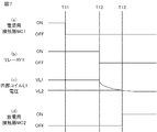
- the operation of the power conversion device 1 when the operation of the electric railway vehicle is stopped will be described with reference to FIG. 7.
- the power conversion unit 11 is stopped, the power contactor MC1 is opened, and the discharge contactor MC2 is turned on.
- the operation of the power conversion device 1 will be described by taking as an example a case where the ascending / descending switch is operated at time T11 and the pantograph descends and is separated from the overhead wire.
- a signal instructing stop is sent to the switching control unit 14 in conjunction with the operation of the ascending / descending switch. Then, the switching control unit 14 turns off the plurality of high-speed switching elements included in the power conversion unit 11 and stops the power conversion unit 11.
- an open / close instruction signal for instructing the opening of the power contactor MC1 is supplied from the driver's cab to each of the contactor control unit 13 and the element control unit 16.
- the contactor control unit 13 to which the opening / closing instruction signal instructing the opening of the power contactor MC1 is supplied outputs the contactor control signal S1 instructing the opening of the power contactor MC1.
- the power contactor MC1 is opened, and the power conversion unit 11 and the filter capacitor FC1 are electrically disconnected from the pantograph, that is, the main power supply.
- the element control unit 16 to which the open / close instruction signal for instructing the opening of the power contactor MC1 is supplied turns off the relay RY1 at the time T12 when the time T12 determined from the time T11 has elapsed.
- the relay RY1 is turned off at the time T12.
- the internal coil L1 is electrically disconnected from the control power supply Vcc, so that the voltage of the internal coil L1 drops from the energized voltage VL1 at time T12 as shown in FIG. 7 (c). start.
- the capacitor discharge resistor R1 When the discharge contactor MC2 is turned on, the capacitor discharge resistor R1 is electrically connected to the filter capacitor FC1, so that the filter capacitor FC1 is discharged.
- the time from the time T12 to the time T13 is determined according to the coil resistance value of the internal coil L1. In other words, the time from time T12 to time T13 is shorter than the time from time T1 to time T2 in the first embodiment.
- the release voltage VL2 is preferably less than a value obtained by multiplying the voltage VL1 at the time of energization by 1 / e.
- the element control unit 16 turns on the relay RY1. Specifically, when the measured value of the voltage between the terminals of the filter capacitor FC1 becomes equal to or less than the threshold voltage, the element control unit 16 turns on the relay RY1. As a result, the internal coil L1 is energized and the discharge contactor MC2 is opened.
- the discharge contactor MC2 is turned on after the power supply contactor MC1 is opened. Therefore, the power supply contactor MC1 and the discharge contactor MC2 are not turned on at the same time. That is, the short-circuit current is suppressed from flowing through the capacitor discharge resistor R1.
- the discharge control circuit 15 included in the power conversion device 1 according to the second embodiment has a control capacitor C2, a coil discharge resistor R2, and a coil discharge resistor R2 like the discharge control circuit 15 included in the power conversion device 1 according to the first embodiment. It is not necessary to provide the diodes D1 and D2. Therefore, the power conversion device 1 according to the second embodiment can be made smaller than the power conversion device 1 according to the first embodiment.
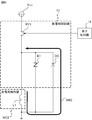
- FIG. 8 shows an example of another circuit configuration of the power conversion device 1.
- the power conversion device 2 shown in FIG. 8 includes a charging contactor MC3 and a charging resistor R3 in addition to the configuration of the power conversion device 1 shown in FIG.
- the charging contactor MC3 and the charging resistor R3 are connected in series. Further, the charging contactor MC3 and the charging resistor R3 connected in series are connected in parallel to the power supply contactor MC1. Specifically, one end of the charging contactor MC3 is connected to a connection point between one end of the power supply contactor MC1 and the positive electrode input terminal 1a. The other end of the charging contactor MC3 is connected to one end of the charging resistor R3. The other end of the charging resistor R3 is connected to the connection point between the other end of the power contactor MC1 and the primary terminal 11a of the power conversion unit 11.
- the charging contactor MC3 is controlled by the contactor control unit 13. Specifically, the contactor control unit 13 outputs the contactor control signal S1 instructing the charging contactor MC3 to turn on when the opening / closing instruction signal instructing to turn on the power contactor MC1 is supplied. As a result, the charging contactor MC3 is turned on, power is supplied from the main power supply to the filter capacitor FC1 via the charging contactor MC3 and the charging resistor R3, and charging of the filter capacitor FC1 is started.
- the contactor control unit 13 acquires a measured value of the voltage between terminals of the filter capacitor FC1 from a voltage measuring unit (not shown). When the measured value of the voltage between the terminals of the filter capacitor FC1 reaches the charging voltage, the contactor control unit 13 included in the power conversion device 2 outputs a contactor control signal S1 instructing the power supply contactor MC1 to be turned on. As a result, the power supply contactor MC1 is turned on, and power is supplied from the main power supply to the filter capacitor FC1 via the power supply contactor MC1.
- the contactor control unit 13 outputs a contactor control signal S1 instructing the power contactor MC1 to be turned on, and then outputs a contactor control signal S1 for opening the charging contactor MC3.
- the charging resistor R3 is electrically disconnected from the main power source. As described above, by turning on the charging contactor MC3 and then turning on the power supply contactor MC1, the inrush current is suppressed from flowing through the filter capacitor FC1.
- FIG. 9 shows an example of another circuit configuration of the power conversion device 1.
- the power conversion device 3 shown in FIG. 9 includes a charging contactor MC4 and a charging resistor R3 in addition to the configuration of the power conversion device 1 according to the first embodiment shown in FIG.
- the charging contactor MC4 is connected to the positive electrode input terminal 1a and one end of the power supply contactor MC1.
- One end of the charging resistor R3 is connected to a connection point between the charging contactor MC4 and the power supply contactor MC1.
- the other end of the charging resistor R3 is connected to the connection point between the power contactor MC1 and the primary terminal 11a of the power conversion unit 11.
- the charging contactor MC4 is controlled by the contactor control unit 13. Specifically, the contactor control unit 13 outputs the contactor control signal S1 instructing the charging contactor MC4 to turn on when the opening / closing instruction signal instructing to turn on the power contactor MC1 is supplied. As a result, the charging contactor MC4 is turned on, power is supplied from the main power supply to the filter capacitor FC1 via the charging contactor MC4 and the charging resistor R3, and charging of the filter capacitor FC1 is started.
- the contactor control unit 13 acquires a measured value of the voltage between terminals of the filter capacitor FC1 from a voltage measuring unit (not shown). When the measured value of the voltage between the terminals of the filter capacitor FC1 reaches the threshold voltage, the contactor control unit 13 included in the power conversion device 3 outputs the contactor control signal S1 instructing the power supply contactor MC1 to be turned on. As a result, the power supply contactor MC1 is turned on, and power is supplied from the main power supply to the filter capacitor FC1 via the charging contactor MC4 and the power supply contactor MC1.
- the element control unit 16 may acquire a state signal indicating whether the power contactor MC1 is turned on or off from the power supply contactor MC1. In this case, when the element control unit 16 detects that the power contactor MC1 has been released from the turned-on state based on the state signal acquired from the power supply contactor MC1, the relay RY1 is turned off. The discharge contactor MC2 may be turned on.
- the power conversion device 1-3 may include a filter reactor provided between the other end of the power contactor MC1 and the primary terminal 11a of the power conversion unit 11. By providing the filter reactor, the input current of the power conversion unit 11 can be smoothed.
- the power conversion unit 11 is an arbitrary power conversion circuit.
- a DC (Direct Current) -DC converter can be used as the power conversion unit 11.
- the discharge control circuit 15 may include an arbitrary switching element such as an IGBT, MOSFET (Metal-Oxide-Semiconductor Field-Effect Transistor), or thyristor instead of the relay RY1. Further, the discharge control circuit 15 included in the power conversion device 1 according to the second embodiment may have the diode D1 as in the first embodiment.
- an arbitrary switching element such as an IGBT, MOSFET (Metal-Oxide-Semiconductor Field-Effect Transistor), or thyristor instead of the relay RY1.
- MOSFET Metal-Oxide-Semiconductor Field-Effect Transistor
- the power conversion device 1-3 is not limited to the auxiliary power supply device, but is an arbitrary power conversion device provided with the filter capacitor FC1.
- the power conversion device 1-3 can be mounted on any vehicle, any device, etc. that can supply power to the power conversion device 1-3.
- the power conversion device 1-3 can be mounted on an AC feeder type electric railway vehicle.
- a transformer whose primary terminal is connected to the pantograph and a converter which is connected to the secondary terminal of the transformer and converts AC power into DC power are provided, and the output of the converter is supplied to the power converter 1-3. Just do it.
- the power conversion device 1-3 may be mounted on an electric railway vehicle that acquires electric power via the third rail.
- 1,2,3 Power converter 1a Positive input terminal, 1b Negative input terminal, 11 Power converter, 11a, 11b Primary terminal, 12 Discharge circuit, 13 Contact control unit, 14 Switching control unit, 15 Discharge control circuit, 16 element control unit, 51 load, AR1, AR2 arrow, B1 surge absorption element, C2 control capacitor, D1, D2, D3 diode, FC1 filter capacitor, L1 internal coil, MC1 power supply contactor, MC2 discharge contactor, MC3, MC4 Charging contact, R1 Capacitor discharge resistance, R2 Coil discharge resistance, R3 Charging resistance, RY1 relay, S1 Contact control signal, S2 Switching control signal, Vcc control power supply.
Abstract
A power conversion device (1) is provided with: a filter capacitor (FC1) that is charged by power supplied from a main power supply; and a power conversion unit (11) for converting power supplied through the filter capacitor (FC1) and supplying the converted power to a load (51). The power conversion device (1) is further provided with: a power supply contactor (MC1) for electrically connecting or disconnecting the filter capacitor (FC1) and the power conversion unit (11) to or from the main power supply; and a discharge circuit (12) connected in parallel with the filter capacitor (FC1). The power conversion device (1) is further provided with a discharge control circuit (15) for, after the power supply contactor (MC1) is opened, switching on a discharge contactor (MC2) possessed by the discharge circuit (12) and discharging the filter capacitor (FC1).
Description
本開示は、電力変換装置に関する。
This disclosure relates to a power conversion device.
電気鉄道車両には、架線を通して変電所から供給された電力を所望の電力に変換し、変換した電力を負荷に供給する電力変換装置が搭載されているものがある。この種の電力変換装置の一例が特許文献1に開示されている。特許文献1に開示される電気車用電源装置は、インバータと、インバータの一次端子間に接続されるフィルタコンデンサと、フィルタコンデンサを放電する放電回路と、インバータおよびフィルタコンデンサを電源に電気的に接続または電源から電気的に切り離す接触器と、を備える。
Some electric railway vehicles are equipped with a power conversion device that converts the power supplied from the substation through the overhead wire into the desired power and supplies the converted power to the load. An example of this type of power conversion device is disclosed in Patent Document 1. The power supply device for an electric vehicle disclosed in Patent Document 1 electrically connects an inverter, a filter capacitor connected between the primary terminals of the inverter, a discharge circuit for discharging the filter capacitor, and the inverter and the filter capacitor to the power supply. Alternatively, it is provided with a contactor that is electrically disconnected from the power source.
特許文献1に開示される電気車用電源装置において、接触器が投入されている状態で誤って放電回路が有する放電用接触器がオンになると、架線から放電用接触器を介して放電回路が有する放電抵抗に短絡電流が流れ、放電抵抗が焼損する可能性がある。
In the electric vehicle power supply device disclosed in Patent Document 1, if the discharge contactor of the discharge circuit is accidentally turned on while the contactor is turned on, the discharge circuit is connected from the overhead wire via the discharge contactor. A short-circuit current may flow through the discharged resistance, and the discharge resistance may burn out.
本開示は上述の事情に鑑みてなされたものであり、放電抵抗に短絡電流が流れることを抑制する電力変換装置を提供することを目的とする。
The present disclosure has been made in view of the above circumstances, and an object of the present disclosure is to provide a power conversion device that suppresses a short-circuit current flowing through a discharge resistor.
上記目的を達成するために、本開示の電力変換装置は、フィルタコンデンサと、電力変換部と、電源用接触器と、放電回路と、放電制御回路と、を備える。フィルタコンデンサは、主電源から供給される電力で充電される。電力変換部の一次端子間にフィルタコンデンサが接続される。また電力変換部は、主電源からフィルタコンデンサを介して供給される電力を、二次端子に接続される負荷に供給するための電力に変換して、変換した電力を負荷に供給する。電源用接触器は、フィルタコンデンサおよび電力変換部を、主電源に電気的に接続、または、主電源から電気的に切り離す。放電回路は、内部コイルを有し、内部コイルが放電されると投入された状態になる放電用接触器と、放電用接触器に直列に接続されたコンデンサ放電抵抗とを有する。また放電回路は、フィルタコンデンサに並列に接続される。放電制御回路は、電源用接触器が開放された後に、放電用接触器が有する内部コイルを放電させることで放電用接触器を投入し、フィルタコンデンサを放電させる。
In order to achieve the above object, the power conversion device of the present disclosure includes a filter capacitor, a power conversion unit, a contactor for a power supply, a discharge circuit, and a discharge control circuit. The filter capacitor is charged with the power supplied from the main power supply. A filter capacitor is connected between the primary terminals of the power converter. Further, the power conversion unit converts the power supplied from the main power supply through the filter capacitor into the power to be supplied to the load connected to the secondary terminal, and supplies the converted power to the load. The power contactor electrically connects the filter capacitor and the power converter to or disconnects from the main power source. The discharge circuit has an internal coil, and has a discharge contactor that is turned on when the internal coil is discharged, and a capacitor discharge resistor connected in series with the discharge contactor. The discharge circuit is also connected in parallel with the filter capacitor. In the discharge control circuit, after the contactor for power supply is opened, the contactor for discharge is turned on by discharging the internal coil of the contactor for discharge, and the filter capacitor is discharged.
本開示によれば、放電制御回路が、電源用接触器が開放された後に、放電用接触器が有する内部コイルを放電させることで放電用接触器を投入し、フィルタコンデンサを放電させる。電源用接触器が開放された後に、放電用接触器が投入されるため、放電抵抗に短絡電流が流れることが抑制される。
According to the present disclosure, the discharge control circuit turns on the discharge contactor by discharging the internal coil of the discharge contactor after the power supply contactor is opened, and discharges the filter capacitor. Since the discharge contactor is turned on after the power supply contactor is opened, the short-circuit current is suppressed from flowing through the discharge resistor.
以下、実施の形態に係る電力変換装置について図面を参照して詳細に説明する。なお図中、同一または同等の部分には同一の符号を付す。
Hereinafter, the power conversion device according to the embodiment will be described in detail with reference to the drawings. In the figure, the same or equivalent parts are designated by the same reference numerals.
(実施の形態1)
車両に搭載される電力変換装置、詳細には、直流き電方式の電気鉄道車両に搭載された補助電源装置を例にして、実施の形態1に係る電力変換装置1について説明する。詳細には、電力変換装置1は、主電源から正極入力端子1aを介して供給された直流電力を負荷51に供給するための電力、例えば三相交流電力に変換して、三相交流電力を負荷51に供給する。 (Embodiment 1)
The power conversion device 1 according to the first embodiment will be described by taking as an example a power conversion device mounted on a vehicle, specifically, an auxiliary power supply device mounted on a DC feeder type electric railway vehicle. Specifically, the power conversion device 1 converts the DC power supplied from the main power supply via thepositive input terminal 1a into the power for supplying the load 51, for example, three-phase AC power, and converts the three-phase AC power into three-phase AC power. It is supplied to the load 51.
車両に搭載される電力変換装置、詳細には、直流き電方式の電気鉄道車両に搭載された補助電源装置を例にして、実施の形態1に係る電力変換装置1について説明する。詳細には、電力変換装置1は、主電源から正極入力端子1aを介して供給された直流電力を負荷51に供給するための電力、例えば三相交流電力に変換して、三相交流電力を負荷51に供給する。 (Embodiment 1)
The power conversion device 1 according to the first embodiment will be described by taking as an example a power conversion device mounted on a vehicle, specifically, an auxiliary power supply device mounted on a DC feeder type electric railway vehicle. Specifically, the power conversion device 1 converts the DC power supplied from the main power supply via the
補助電源装置である電力変換装置1は、停止後の再起動を速やかに行うため、停止時に後述のフィルタコンデンサFC1を速やかに放電させる必要がある。このため、詳細については後述するが、フィルタコンデンサFC1を放電させるための放電回路12は、放電用接触器MC2を備える。電力変換装置1の停止時に、電源用接触器MC1が開放されてから、放電用接触器MC2を投入することで、放電回路12のコンデンサ放電抵抗R1に短絡電流が流れることが抑制される。
Since the power conversion device 1 which is an auxiliary power supply device restarts quickly after being stopped, it is necessary to quickly discharge the filter capacitor FC1 described later when the power is stopped. Therefore, although the details will be described later, the discharge circuit 12 for discharging the filter capacitor FC1 includes a discharge contactor MC2. By turning on the discharge contactor MC2 after the power supply contactor MC1 is opened when the power conversion device 1 is stopped, the short-circuit current is suppressed from flowing through the capacitor discharge resistor R1 of the discharge circuit 12.
電力変換装置1の構成について以下に説明する。電力変換装置1は、主電源に接続される正極入力端子1aと、接地される負極入力端子1bと、一端が正極入力端子1aに接続される電源用接触器MC1と、一端が電源用接触器MC1の他端に接続され、他端が負極入力端子1bに接続されるフィルタコンデンサFC1と、を備える。電力変換装置1はさらに、一次端子11aを介して供給される直流電力を三相交流電力に変換して、負荷51に供給する電力変換部11と、フィルタコンデンサFC1に並列に接続される放電回路12と、を備える。
The configuration of the power conversion device 1 will be described below. The power conversion device 1 includes a positive electrode input terminal 1a connected to a main power supply, a grounded negative electrode input terminal 1b, a power supply contactor MC1 having one end connected to the positive electrode input terminal 1a, and a power supply contactor at one end. It includes a filter capacitor FC1 which is connected to the other end of the MC1 and the other end is connected to the negative electrode input terminal 1b. The power conversion device 1 further converts the DC power supplied via the primary terminal 11a into three-phase AC power, and supplies the power conversion unit 11 to the load 51, and a discharge circuit connected in parallel to the filter capacitor FC1. 12 and.
電力変換装置1はさらに、電源用接触器MC1の制御を行う接触器制御部13と、電力変換部11の制御を行うスイッチング制御部14と、放電回路12が有する放電用接触器MC2を制御する放電制御回路15と、放電制御回路15が有するスイッチング素子である後述のリレーRY1を制御する素子制御部16と、を備える。
The power conversion device 1 further controls a contactor control unit 13 that controls the power supply contactor MC1, a switching control unit 14 that controls the power conversion unit 11, and a discharge contactor MC2 included in the discharge circuit 12. It includes a discharge control circuit 15 and an element control unit 16 that controls a relay RY1 described later, which is a switching element included in the discharge control circuit 15.
電力変換装置1の構成の詳細について以下に説明する。
正極入力端子1aは、主電源、例えば架線を介して変電所から電力を取得するパンタグラフに接続される。負極入力端子1bは、例えば、接地ブラシ、車輪、およびレールを介して接地される。 The details of the configuration of the power conversion device 1 will be described below.
The positiveelectrode input terminal 1a is connected to a pantograph that obtains power from a substation via a main power source, for example, an overhead wire. The negative electrode input terminal 1b is grounded via, for example, a grounding brush, wheels, and rails.
正極入力端子1aは、主電源、例えば架線を介して変電所から電力を取得するパンタグラフに接続される。負極入力端子1bは、例えば、接地ブラシ、車輪、およびレールを介して接地される。 The details of the configuration of the power conversion device 1 will be described below.
The positive
電源用接触器MC1の一端は正極入力端子1aに接続され、他端は電力変換部11の一次端子11a、フィルタコンデンサFC1の一端、および放電回路12の一端のそれぞれに接続される。電源用接触器MC1は、直流電磁接触器であり、接触器制御部13によって制御される。
One end of the power contactor MC1 is connected to the positive electrode input terminal 1a, and the other end is connected to each of the primary terminal 11a of the power conversion unit 11, one end of the filter capacitor FC1, and one end of the discharge circuit 12. The power contactor MC1 is a DC magnetic contactor and is controlled by the contactor control unit 13.
接触器制御部13が電源用接触器MC1を投入すると、電源用接触器MC1の一端と他端は互いに接続される。この結果、電力変換部11およびフィルタコンデンサFC1は、主電源に電気的に接続され、主電源から電力の供給を受ける。
また接触器制御部13が電源用接触器MC1を開放すると、電源用接触器MC1の一端と他端は絶縁される。この結果、電力変換部11およびフィルタコンデンサFC1は、主電源から電気的に切り離され、主電源から電力の供給を受けることができない。 When thecontactor control unit 13 turns on the power contactor MC1, one end and the other end of the power supply contactor MC1 are connected to each other. As a result, the power conversion unit 11 and the filter capacitor FC1 are electrically connected to the main power supply and receive power from the main power supply.
Further, when thecontactor control unit 13 opens the power supply contactor MC1, one end and the other end of the power supply contactor MC1 are insulated. As a result, the power conversion unit 11 and the filter capacitor FC1 are electrically disconnected from the main power supply, and cannot receive power from the main power supply.
また接触器制御部13が電源用接触器MC1を開放すると、電源用接触器MC1の一端と他端は絶縁される。この結果、電力変換部11およびフィルタコンデンサFC1は、主電源から電気的に切り離され、主電源から電力の供給を受けることができない。 When the
Further, when the
フィルタコンデンサFC1は、電力変換部11の一次端子11a,11bの間に接続され、主電源から供給される電力で充電される。詳細には、フィルタコンデンサFC1の一端は、電源用接触器MC1と電力変換部11の一次端子11aとの接続点に接続される。またフィルタコンデンサFC1の他端は、負極入力端子1bと電力変換部11の一次端子11bとの接続点に接続される。
The filter capacitor FC1 is connected between the primary terminals 11a and 11b of the power conversion unit 11 and is charged by the power supplied from the main power supply. Specifically, one end of the filter capacitor FC1 is connected to a connection point between the power contactor MC1 and the primary terminal 11a of the power conversion unit 11. The other end of the filter capacitor FC1 is connected to the connection point between the negative electrode input terminal 1b and the primary terminal 11b of the power conversion unit 11.
電力変換部11は、一次端子11aを介して供給された直流電力を三相交流電力に変換し、三相交流電力を各二次端子に接続された負荷51に供給する。詳細には、電力変換部11は、高速スイッチングが可能な複数の高速スイッチング素子、例えば、IGBT(Insulated Gate Bipolar Transistor:絶縁ゲート型バイポーラトランジスタ)を有する。複数の高速スイッチング素子がスイッチング制御部14によって制御され、オンオフを繰り返すことで、上述したように、電力変換部11は、直流電力を三相交流電力に変換し、三相交流電力を負荷51に供給する。なお負荷51は、照明機器、空調機器等の任意の車載機器である。
The power conversion unit 11 converts the DC power supplied via the primary terminal 11a into three-phase AC power, and supplies the three-phase AC power to the load 51 connected to each secondary terminal. Specifically, the power conversion unit 11 has a plurality of high-speed switching elements capable of high-speed switching, for example, an IGBT (Insulated Gate Bipolar Transistor). A plurality of high-speed switching elements are controlled by the switching control unit 14 and repeatedly turned on and off, so that the power conversion unit 11 converts DC power into three-phase AC power and converts the three-phase AC power into the load 51 as described above. Supply. The load 51 is an arbitrary in-vehicle device such as a lighting device and an air conditioner.
放電回路12は、フィルタコンデンサFC1に並列に接続される。詳細には、放電回路12の一端は、電源用接触器MC1の他端と電力変換部11の一次端子11aの接続点に接続される。また放電回路12の他端は、負極入力端子1bと電力変換部11の一次端子11bとの接続点に接続される。
The discharge circuit 12 is connected in parallel with the filter capacitor FC1. Specifically, one end of the discharge circuit 12 is connected to the other end of the power contactor MC1 and the connection point of the primary terminal 11a of the power conversion unit 11. The other end of the discharge circuit 12 is connected to the connection point between the negative electrode input terminal 1b and the primary terminal 11b of the power conversion unit 11.
また放電回路12は、コンデンサ放電抵抗R1と、コンデンサ放電抵抗R1に直列に接続された放電用接触器MC2と、を備える。放電回路12の各部について説明する。
コンデンサ放電抵抗R1の一端は、電源用接触器MC1の他端と電力変換部11の一次端子11aとの接続点に接続される。コンデンサ放電抵抗R1の抵抗値は、フィルタコンデンサFC1を定められた時間で放電することができる値であれば、任意である。 Further, thedischarge circuit 12 includes a capacitor discharge resistor R1 and a discharge contactor MC2 connected in series with the capacitor discharge resistor R1. Each part of the discharge circuit 12 will be described.
One end of the capacitor discharge resistor R1 is connected to the connection point between the other end of the power contactor MC1 and theprimary terminal 11a of the power conversion unit 11. The resistance value of the capacitor discharge resistor R1 is arbitrary as long as the filter capacitor FC1 can be discharged in a predetermined time.
コンデンサ放電抵抗R1の一端は、電源用接触器MC1の他端と電力変換部11の一次端子11aとの接続点に接続される。コンデンサ放電抵抗R1の抵抗値は、フィルタコンデンサFC1を定められた時間で放電することができる値であれば、任意である。 Further, the
One end of the capacitor discharge resistor R1 is connected to the connection point between the other end of the power contactor MC1 and the
放電用接触器MC2の一端はコンデンサ放電抵抗R1の他端に接続され、他端は負極入力端子1bと電力変換部11の一次端子11bとの接続点に接続される。また放電用接触器MC2は、直流電磁接触器であり、放電制御回路15によって制御される。
One end of the discharge contactor MC2 is connected to the other end of the capacitor discharge resistor R1, and the other end is connected to the connection point between the negative electrode input terminal 1b and the primary terminal 11b of the power conversion unit 11. The discharge contactor MC2 is a DC electromagnetic contactor and is controlled by the discharge control circuit 15.
放電制御回路15が放電用接触器MC2を投入すると、放電用接触器MC2の一端と他端は互いに接続される。この結果、フィルタコンデンサFC1とコンデンサ放電抵抗R1が電気的に接続される。そして、フィルタコンデンサFC1からコンデンサ放電抵抗R1に電流が流れることで、フィルタコンデンサFC1が放電される。
また放電制御回路15が放電用接触器MC2を開放すると、放電用接触器MC2の一端と他端は絶縁される。この場合、フィルタコンデンサFC1とコンデンサ放電抵抗R1は電気的に接続されていないため、コンデンサ放電抵抗R1によるフィルタコンデンサFC1の放電は行われない。 When thedischarge control circuit 15 turns on the discharge contactor MC2, one end and the other end of the discharge contactor MC2 are connected to each other. As a result, the filter capacitor FC1 and the capacitor discharge resistor R1 are electrically connected. Then, the filter capacitor FC1 is discharged by the current flowing from the filter capacitor FC1 to the capacitor discharge resistor R1.
When thedischarge control circuit 15 opens the discharge contactor MC2, one end and the other end of the discharge contactor MC2 are insulated. In this case, since the filter capacitor FC1 and the capacitor discharge resistor R1 are not electrically connected, the filter capacitor FC1 is not discharged by the capacitor discharge resistor R1.
また放電制御回路15が放電用接触器MC2を開放すると、放電用接触器MC2の一端と他端は絶縁される。この場合、フィルタコンデンサFC1とコンデンサ放電抵抗R1は電気的に接続されていないため、コンデンサ放電抵抗R1によるフィルタコンデンサFC1の放電は行われない。 When the
When the
なお放電用接触器MC2として、図2に示すように、内部コイルL1を有し、内部コイルL1が放電されると投入された状態になり、内部コイルL1が通電されると開放された状態となるB接点形の直流電磁接触器が用いられる。なお内部コイルL1の一端は、詳細については後述するが、放電制御回路15によって、制御電源Vccに電気的に接続、または制御電源Vccから電気的に切り離される。なお制御電源Vccは、主電源とは独立した電源であり、例えば電気鉄道車両に搭載されたバッテリーである。また内部コイルL1の他端は、接地されている。
As shown in FIG. 2, the discharge contactor MC2 has an internal coil L1 and is in a state of being turned on when the internal coil L1 is discharged, and in a state of being opened when the internal coil L1 is energized. A B-contact type DC electromagnetic contactor is used. One end of the internal coil L1 will be described in detail later, but is electrically connected to or electrically disconnected from the control power supply Vcc by the discharge control circuit 15. The control power supply Vcc is a power supply independent of the main power supply, and is, for example, a battery mounted on an electric railway vehicle. The other end of the internal coil L1 is grounded.
図1に示す接触器制御部13には、図示しない運転台から、電源用接触器MC1の投入または開放を指示する開閉指示信号が供給される。接触器制御部13は、開閉指示信号に従って、電源用接触器MC1を投入または開放する。詳細には、接触器制御部13は、電源用接触器MC1に投入または開放を指示する接触器制御信号S1を送り、電源用接触器MC1を制御する。
The contactor control unit 13 shown in FIG. 1 is supplied with an open / close instruction signal instructing to turn on or open the power contactor MC1 from a driver's cab (not shown). The contactor control unit 13 turns on or opens the power contactor MC1 according to the open / close instruction signal. Specifically, the contactor control unit 13 sends a contactor control signal S1 instructing the contactor MC1 for power supply to turn on or open, and controls the contactor MC1 for power supply.
スイッチング制御部14は、図示しない電圧測定部からフィルタコンデンサFC1の端子間電圧の測定値を取得する。そして、スイッチング制御部14は、電源用接触器MC1が投入されてフィルタコンデンサFC1が充電された後、電力変換部11が有する高速スイッチング素子のオンオフ制御を開始する。詳細には、フィルタコンデンサFC1の端子間電圧の測定値が充電電圧に到達した後、スイッチング制御部14は、複数の高速スイッチング素子のそれぞれに、オンオフの繰り返しを指示するスイッチング制御信号S2を送る。この結果、電力変換部11は、主電源から供給される直流電力を三相交流電力に変換し、負荷51に三相交流電力を供給する。
The switching control unit 14 acquires a measured value of the voltage between terminals of the filter capacitor FC1 from a voltage measuring unit (not shown). Then, after the power contactor MC1 is turned on and the filter capacitor FC1 is charged, the switching control unit 14 starts on / off control of the high-speed switching element of the power conversion unit 11. Specifically, after the measured value of the inter-terminal voltage of the filter capacitor FC1 reaches the charging voltage, the switching control unit 14 sends a switching control signal S2 instructing each of the plurality of high-speed switching elements to repeat on / off. As a result, the power conversion unit 11 converts the DC power supplied from the main power source into the three-phase AC power, and supplies the three-phase AC power to the load 51.
放電制御回路15は、放電用接触器MC2が有する内部コイルL1を放電させ、または通電させることで、放電用接触器MC2を制御する。放電制御回路15の構成の詳細について以下に説明する。
放電制御回路15は、図2に示すように、スイッチング素子であるリレーRY1と、直列に接続されたコイル放電抵抗R2および制御用コンデンサC2と、を備える。詳細については後述するが、リレーRY1がオフになった場合に、制御電源Vccに電流が逆流することを防ぎながら内部コイルL1を放電するために、放電制御回路15は、ダイオードD1,D2を備えることが好ましい。 Thedischarge control circuit 15 controls the discharge contactor MC2 by discharging or energizing the internal coil L1 of the discharge contactor MC2. The details of the configuration of the discharge control circuit 15 will be described below.
As shown in FIG. 2, thedischarge control circuit 15 includes a relay RY1 which is a switching element, a coil discharge resistor R2 connected in series, and a control capacitor C2. Although the details will be described later, the discharge control circuit 15 includes diodes D1 and D2 in order to discharge the internal coil L1 while preventing the current from flowing back to the control power supply Vcc when the relay RY1 is turned off. Is preferable.
放電制御回路15は、図2に示すように、スイッチング素子であるリレーRY1と、直列に接続されたコイル放電抵抗R2および制御用コンデンサC2と、を備える。詳細については後述するが、リレーRY1がオフになった場合に、制御電源Vccに電流が逆流することを防ぎながら内部コイルL1を放電するために、放電制御回路15は、ダイオードD1,D2を備えることが好ましい。 The
As shown in FIG. 2, the
リレーRY1の一端は、制御電源Vccに接続される。またリレーRY1の他端は、ダイオードD1を介して内部コイルL1の一端に接続される。
リレーRY1は、内部コイルL1を、制御電源Vccに電気的に接続、または制御電源Vccから電気的に切り離す。またリレーRY1は、素子制御部16によって制御される。 One end of the relay RY1 is connected to the control power supply Vcc. The other end of the relay RY1 is connected to one end of the internal coil L1 via the diode D1.
The relay RY1 electrically connects the internal coil L1 to the control power supply Vcc or electrically disconnects it from the control power supply Vcc. The relay RY1 is controlled by theelement control unit 16.
リレーRY1は、内部コイルL1を、制御電源Vccに電気的に接続、または制御電源Vccから電気的に切り離す。またリレーRY1は、素子制御部16によって制御される。 One end of the relay RY1 is connected to the control power supply Vcc. The other end of the relay RY1 is connected to one end of the internal coil L1 via the diode D1.
The relay RY1 electrically connects the internal coil L1 to the control power supply Vcc or electrically disconnects it from the control power supply Vcc. The relay RY1 is controlled by the
ダイオードD1のアノードは、リレーRY1の他端に接続される。またダイオードD1のカソードは、内部コイルL1の一端に接続される。ダイオードD1は、制御電源Vccへの電流の逆流を抑制する。
The anode of the diode D1 is connected to the other end of the relay RY1. Further, the cathode of the diode D1 is connected to one end of the internal coil L1. The diode D1 suppresses the backflow of current to the control power supply Vcc.
ダイオードD2のアノードは、コイル放電抵抗R2と制御用コンデンサC2との接続点に接続される。またダイオードD2のカソードは、内部コイルL1の一端に接続される。ダイオードD2は、後述するコイル放電抵抗R2の他端から一端に向かう電路を形成することで、内部コイルL1をコイル放電抵抗R2および制御用コンデンサC2によって放電することを可能とする。
The anode of the diode D2 is connected to the connection point between the coil discharge resistor R2 and the control capacitor C2. Further, the cathode of the diode D2 is connected to one end of the internal coil L1. The diode D2 makes it possible to discharge the internal coil L1 by the coil discharge resistor R2 and the control capacitor C2 by forming an electric circuit from the other end to one end of the coil discharge resistor R2, which will be described later.
コイル放電抵抗R2は、一端がダイオードD1と内部コイルL1との接続点に接続され、他端が制御用コンデンサC2の一端に接続される。なおコイル放電抵抗R2の抵抗値は、内部コイルL1を所望の時間で放電することができる任意の抵抗値である。所望の時間は、例えば、電力変換装置1の再起動に要する時間の目標値に応じて、定められればよい。
制御用コンデンサC2の他端は、内部コイルL1の他端に接続される。 One end of the coil discharge resistor R2 is connected to the connection point between the diode D1 and the internal coil L1, and the other end is connected to one end of the control capacitor C2. The resistance value of the coil discharge resistor R2 is an arbitrary resistance value capable of discharging the internal coil L1 at a desired time. The desired time may be determined, for example, according to a target value of the time required for restarting the power conversion device 1.
The other end of the control capacitor C2 is connected to the other end of the internal coil L1.
上記構成を有する放電制御回路15において、リレーRY1が素子制御部16によってオンにされると、内部コイルL1は、制御電源Vccに電気的に接続される。内部コイルL1が通電されるため、放電用接触器MC2は、開放された状態である。
またリレーRY1が素子制御部16によってオフにされると、内部コイルL1は、制御電源Vccから電気的に切り離される。この結果、図3において矢印AR1で示すように、内部コイルL1から、制御用コンデンサC2を介して、コイル放電抵抗R2およびダイオードD2に電流が流れ、内部コイルL1は放電される。内部コイルL1が放電されると、放電用接触器MC2は投入された状態となる。 In thedischarge control circuit 15 having the above configuration, when the relay RY1 is turned on by the element control unit 16, the internal coil L1 is electrically connected to the control power supply Vcc. Since the internal coil L1 is energized, the discharge contactor MC2 is in an open state.
When the relay RY1 is turned off by theelement control unit 16, the internal coil L1 is electrically disconnected from the control power supply Vcc. As a result, as shown by the arrow AR1 in FIG. 3, a current flows from the internal coil L1 to the coil discharge resistor R2 and the diode D2 via the control capacitor C2, and the internal coil L1 is discharged. When the internal coil L1 is discharged, the discharge contactor MC2 is in the charged state.
またリレーRY1が素子制御部16によってオフにされると、内部コイルL1は、制御電源Vccから電気的に切り離される。この結果、図3において矢印AR1で示すように、内部コイルL1から、制御用コンデンサC2を介して、コイル放電抵抗R2およびダイオードD2に電流が流れ、内部コイルL1は放電される。内部コイルL1が放電されると、放電用接触器MC2は投入された状態となる。 In the
When the relay RY1 is turned off by the
図1に示す素子制御部16には、接触器制御部13と同様に、電源用接触器MC1の投入または開放を指示する開閉指示信号が供給される。素子制御部16は、電源用接触器MC1が投入された状態および開放された状態のいずれであるかに応じて、放電制御回路15が有するリレーRY1をオンまたはオフにする。詳細には、素子制御部16は、電源用接触器MC1が投入されている間は、リレーRY1をオンに維持する。また素子制御部16は、電源用接触器MC1が投入された状態から開放されると、リレーRY1を直ちにオフにする。
Similar to the contactor control unit 13, the element control unit 16 shown in FIG. 1 is supplied with an open / close instruction signal instructing to turn on or open the power contactor MC1. The element control unit 16 turns on or off the relay RY1 of the discharge control circuit 15 depending on whether the power contactor MC1 is turned on or open. Specifically, the element control unit 16 keeps the relay RY1 on while the power contactor MC1 is turned on. Further, the element control unit 16 immediately turns off the relay RY1 when the power contactor MC1 is released from the turned-on state.
また素子制御部16は、電圧測定部からフィルタコンデンサFC1の端子間電圧の測定値を取得する。リレーRY1がオフになった後に、フィルタコンデンサFC1の端子間電圧の測定値が閾値電圧以下となると、素子制御部16は、リレーRY1をオンにする。これにより、フィルタコンデンサFC1の放電完了後に放電用接触器MC2が開放されることになる。
Further, the element control unit 16 acquires the measured value of the voltage between the terminals of the filter capacitor FC1 from the voltage measurement unit. When the measured value of the voltage between the terminals of the filter capacitor FC1 becomes equal to or less than the threshold voltage after the relay RY1 is turned off, the element control unit 16 turns on the relay RY1. As a result, the discharge contactor MC2 is opened after the discharge of the filter capacitor FC1 is completed.
次に、上記構成を有する電力変換装置1の動作について説明する。
電気鉄道車両の始動時に、パンタグラフを上昇または下降させる上昇下降スイッチの操作が行われて、パンタグラフが上昇し、架線に接触すると、パンタグラフは、変電所から架線を介して電力を取得する。なお電気鉄道車両の始動時には、電源用接触器MC1および放電用接触器MC2のいずれも開放された状態であるとする。 Next, the operation of the power conversion device 1 having the above configuration will be described.
When the electric railway vehicle is started, an ascending / descending switch that raises or lowers the pantograph is operated, and when the pantograph rises and comes into contact with the overhead wire, the pantograph obtains electric power from the substation via the overhead wire. It is assumed that both the power contactor MC1 and the discharge contactor MC2 are in the open state when the electric railway vehicle is started.
また上昇下降スイッチの操作に連動して、開閉指示信号が運転台から接触器制御部13および素子制御部16のそれぞれに供給される。詳細には、上昇下降スイッチの操作によって、パンタグラフが上昇すると、電源用接触器MC1の投入を指示する開閉指示信号が運転台から接触器制御部13および素子制御部16のそれぞれに供給される。
Further, in conjunction with the operation of the ascending / descending switch, an open / close instruction signal is supplied from the driver's cab to each of the contactor control unit 13 and the element control unit 16. Specifically, when the pantograph is raised by operating the ascending / descending switch, an open / close instruction signal for instructing the power supply contactor MC1 to be turned on is supplied from the driver's cab to each of the contactor control unit 13 and the element control unit 16.
接触器制御部13は、電源用接触器MC1の投入を指示する開閉指示信号が供給されると、電源用接触器MC1の投入を指示する接触器制御信号S1を出力する。この結果、電源用接触器MC1が投入され、パンタグラフが架線を介して変電所から取得した電力が、電源用接触器MC1を介して、フィルタコンデンサFC1に供給され、フィルタコンデンサFC1の充電が開始される。
When the contactor control unit 13 is supplied with an open / close instruction signal instructing the power supply contactor MC1 to be turned on, the contactor control unit 13 outputs a contactor control signal S1 instructing the power supply contactor MC1 to be turned on. As a result, the power contactor MC1 is turned on, the power acquired by the pantograph from the substation via the overhead wire is supplied to the filter capacitor FC1 via the power supply contactor MC1, and charging of the filter capacitor FC1 is started. NS.
素子制御部16は、電源用接触器MC1の投入を指示する開閉指示信号が供給されると、リレーRY1をオンに維持する。この結果、内部コイルL1が通電され、放電用接触器MC2は、開放された状態に維持される。
The element control unit 16 keeps the relay RY1 on when an open / close instruction signal for instructing the power supply contactor MC1 to be turned on is supplied. As a result, the internal coil L1 is energized, and the discharge contactor MC2 is maintained in an open state.
その後、フィルタコンデンサFC1が十分に充電されると、スイッチング制御部14は、電力変換部11の高速スイッチング素子のオンオフ制御を開始する。スイッチング制御部14に制御された高速スイッチング素子は、オンオフを繰り返す。この結果、電力変換部11は、フィルタコンデンサFC1を介して供給される直流電力を三相交流電力に変換し、三相交流電力を負荷51に供給する。
After that, when the filter capacitor FC1 is sufficiently charged, the switching control unit 14 starts on / off control of the high-speed switching element of the power conversion unit 11. The high-speed switching element controlled by the switching control unit 14 repeats on / off. As a result, the power conversion unit 11 converts the DC power supplied through the filter capacitor FC1 into three-phase AC power, and supplies the three-phase AC power to the load 51.
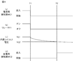
次に、電気鉄道車両の運転停止時の電力変換装置1の動作について図4を用いて説明する。電気鉄道車両の運転を停止する際には、電力変換部11が停止され、電源用接触器MC1が開放され、放電用接触器MC2が投入される。時刻T1において、上昇下降スイッチの操作が行われて、パンタグラフが下降し、架線から離隔する場合を例にして、電力変換装置1の動作について説明する。
Next, the operation of the power conversion device 1 when the operation of the electric railway vehicle is stopped will be described with reference to FIG. When the operation of the electric railway vehicle is stopped, the power conversion unit 11 is stopped, the power contactor MC1 is opened, and the discharge contactor MC2 is turned on. The operation of the power conversion device 1 will be described by taking as an example a case where the ascending / descending switch is operated at time T1 and the pantograph descends and is separated from the overhead wire.
時刻T1において、上昇下降スイッチの操作に連動して、停止を指示する信号がスイッチング制御部14に送られる。そして、スイッチング制御部14は、電力変換部11が有する複数の高速スイッチング素子をオフにし、電力変換部11を停止させる。
At time T1, a signal instructing stop is sent to the switching control unit 14 in conjunction with the operation of the ascending / descending switch. Then, the switching control unit 14 turns off the plurality of high-speed switching elements included in the power conversion unit 11 and stops the power conversion unit 11.
また時刻T1において、上昇下降スイッチの操作によってパンタグラフが下降すると、電源用接触器MC1の開放を指示する開閉指示信号が運転台から接触器制御部13および素子制御部16のそれぞれに供給される。
Further, at time T1, when the pantograph is lowered by operating the ascending / descending switch, an open / close instruction signal for instructing the opening of the power contactor MC1 is supplied from the driver's cab to each of the contactor control unit 13 and the element control unit 16.
電源用接触器MC1の開放を指示する開閉指示信号が供給された接触器制御部13は、電源用接触器MC1の開放を指示する接触器制御信号S1を出力する。この結果、図4(a)に示すように、時刻T1において、電源用接触器MC1が開放され、電力変換部11およびフィルタコンデンサFC1は、パンタグラフ、すなわち主電源から電気的に切り離される。
The contactor control unit 13 to which the opening / closing instruction signal instructing the opening of the power contactor MC1 is supplied outputs the contactor control signal S1 instructing the opening of the power contactor MC1. As a result, as shown in FIG. 4A, at time T1, the power contactor MC1 is opened, and the power conversion unit 11 and the filter capacitor FC1 are electrically disconnected from the pantograph, that is, the main power supply.
また電源用接触器MC1の開放を指示する開閉指示信号が供給された素子制御部16は、リレーRY1をオフにする。この結果、図4(b)に示すように、時刻T1において、リレーRY1がオフになる。リレーRY1がオフになると内部コイルL1は制御電源Vccから電気的に切り離されるため、内部コイルL1の電圧は、図4(c)に示すように、時刻T1において、通電時の電圧VL1から低下し始める。
Further, the element control unit 16 to which the open / close instruction signal for instructing the opening of the power contactor MC1 is supplied turns off the relay RY1. As a result, as shown in FIG. 4B, the relay RY1 is turned off at the time T1. When the relay RY1 is turned off, the internal coil L1 is electrically disconnected from the control power supply Vcc, so that the voltage of the internal coil L1 drops from the energized voltage VL1 at time T1 as shown in FIG. 4C. start.
その後、図4(c)に示すように、時刻T2において、内部コイルL1の電圧が釈放電圧VL2まで低下する。この結果、時刻T2において、図4(d)に示すように、放電用接触器MC2は投入される。
After that, as shown in FIG. 4C, at time T2, the voltage of the internal coil L1 drops to the release voltage VL2. As a result, at time T2, as shown in FIG. 4D, the discharge contactor MC2 is turned on.
放電用接触器MC2が投入されると、コンデンサ放電抵抗R1がフィルタコンデンサFC1に電気的に接続されるため、フィルタコンデンサFC1は放電される。なお時刻T1から時刻T2までの時間は、コンデンサ放電抵抗R1の抵抗値に内部コイルL1のコイル抵抗値を加算した結果にフィルタコンデンサFC1の静電容量を乗算して得られる時定数に応じて決まる。また釈放電圧VL2は、通電時の電圧VL1に1/eを乗算した値未満であることが好ましい。なおeは、自然対数である。
When the discharge contactor MC2 is turned on, the capacitor discharge resistor R1 is electrically connected to the filter capacitor FC1, so that the filter capacitor FC1 is discharged. The time from time T1 to time T2 is determined according to the time constant obtained by multiplying the result of adding the coil resistance value of the internal coil L1 to the resistance value of the capacitor discharge resistance R1 by the capacitance of the filter capacitor FC1. .. Further, the release voltage VL2 is preferably less than a value obtained by multiplying the voltage VL1 at the time of energization by 1 / e. Note that e is a natural logarithm.
その後、フィルタコンデンサFC1の放電が完了すると、素子制御部16は、リレーRY1をオンにする。詳細には、フィルタコンデンサFC1の端子間電圧の測定値が閾値電圧以下となると、素子制御部16は、リレーRY1をオンにする。この結果、内部コイルL1が通電され、放電用接触器MC2は開放される。
After that, when the discharge of the filter capacitor FC1 is completed, the element control unit 16 turns on the relay RY1. Specifically, when the measured value of the voltage between the terminals of the filter capacitor FC1 becomes equal to or less than the threshold voltage, the element control unit 16 turns on the relay RY1. As a result, the internal coil L1 is energized and the discharge contactor MC2 is opened.
以上説明した通り、実施の形態1に係る電力変換装置1において、放電用接触器MC2は、電源用接触器MC1が開放された後に投入される。このため、電源用接触器MC1と放電用接触器MC2とは同時に投入された状態にならない。すなわち、コンデンサ放電抵抗R1に短絡電流が流れることが抑制される。
As described above, in the power conversion device 1 according to the first embodiment, the discharge contactor MC2 is turned on after the power supply contactor MC1 is opened. Therefore, the power supply contactor MC1 and the discharge contactor MC2 are not turned on at the same time. That is, the short-circuit current is suppressed from flowing through the capacitor discharge resistor R1.
またコンデンサ放電抵抗R1に短絡電流が流れることが抑制されるため、コンデンサ放電抵抗R1に短絡電流が流れて焼損することを防ぐために、コンデンサ放電抵抗R1の容量を大きくする必要がない。換言すれば、コンデンサ放電抵抗R1の容量を大きくすることに伴ってコンデンサ放電抵抗R1が大型化することが抑制される。この結果、電力変換装置1の大型化が抑制される。
Further, since the short-circuit current is suppressed from flowing through the capacitor discharge resistor R1, it is not necessary to increase the capacitance of the capacitor discharge resistor R1 in order to prevent the short-circuit current from flowing through the capacitor discharge resistor R1 and causing burning. In other words, it is suppressed that the capacitor discharge resistor R1 becomes larger as the capacitance of the capacitor discharge resistor R1 increases. As a result, the increase in size of the power conversion device 1 is suppressed.
(実施の形態2)
放電制御回路15の構成は、実施の形態1の例に限られない。詳細には、放電制御回路15の構成は、電源用接触器MC1が開放された後に放電用接触器MC2を投入することができる構成であれば、任意である。 (Embodiment 2)
The configuration of thedischarge control circuit 15 is not limited to the example of the first embodiment. Specifically, the configuration of the discharge control circuit 15 is arbitrary as long as the discharge contactor MC2 can be turned on after the power supply contactor MC1 is opened.
放電制御回路15の構成は、実施の形態1の例に限られない。詳細には、放電制御回路15の構成は、電源用接触器MC1が開放された後に放電用接触器MC2を投入することができる構成であれば、任意である。 (Embodiment 2)
The configuration of the
実施の形態2に係る電力変換装置1の構成は、実施の形態1と同様である。図5に示すように、実施の形態2に係る電力変換装置1が備える放電制御回路15は、スイッチング素子であるリレーRY1と、放電用接触器MC2の内部コイルL1に並列に接続されたダイオードD3と、を備える。さらに電力変換装置1は、放電用接触器MC2の内部コイルL1に並列に接続されたサージ吸収素子B1を備えることが好ましい。
The configuration of the power conversion device 1 according to the second embodiment is the same as that of the first embodiment. As shown in FIG. 5, the discharge control circuit 15 included in the power conversion device 1 according to the second embodiment is a diode D3 connected in parallel to the relay RY1 which is a switching element and the internal coil L1 of the discharge contactor MC2. And. Further, the power conversion device 1 preferably includes a surge absorbing element B1 connected in parallel to the internal coil L1 of the discharge contactor MC2.
リレーRY1の一端は、制御電源Vccに接続される。またリレーRY1の他端は、内部コイルL1の一端に接続される。なおリレーRY1の構造および動作は、実施の形態1と同様である。
One end of the relay RY1 is connected to the control power supply Vcc. The other end of the relay RY1 is connected to one end of the internal coil L1. The structure and operation of the relay RY1 are the same as those in the first embodiment.
ダイオードD3は、内部コイルL1に並列に接続される。詳細には、ダイオードD3のアノードは、内部コイルL1の他端に接続される。ダイオードD3のカソードは、リレーRY1と内部コイルL1との接続点に接続される。
The diode D3 is connected in parallel to the internal coil L1. Specifically, the anode of the diode D3 is connected to the other end of the internal coil L1. The cathode of the diode D3 is connected to the connection point between the relay RY1 and the internal coil L1.
サージ吸収素子B1は、内部コイルL1に並列に接続される。詳細には、サージ吸収素子B1はバリスタであり、内部コイルL1の放電時に、並列に接続されている素子、すなわちダイオードD3に過電圧が印加されることを抑制する。
The surge absorbing element B1 is connected in parallel to the internal coil L1. Specifically, the surge absorbing element B1 is a varistor, and suppresses the application of an overvoltage to an element connected in parallel, that is, a diode D3, when the internal coil L1 is discharged.
上記構成を有する放電制御回路15において、リレーRY1が素子制御部16によってオンにされると、内部コイルL1は、制御電源Vccに電気的に接続される。内部コイルL1が通電されるため、放電用接触器MC2は、開放された状態である。
またリレーRY1が素子制御部16によってオフにされると、内部コイルL1は、制御電源Vccから電気的に切り離される。この結果、図6において矢印AR2で示すように、内部コイルL1から、ダイオードD3に電流が流れ、内部コイルL1は放電される。内部コイルL1が放電されると、放電用接触器MC2は投入された状態となる。 In thedischarge control circuit 15 having the above configuration, when the relay RY1 is turned on by the element control unit 16, the internal coil L1 is electrically connected to the control power supply Vcc. Since the internal coil L1 is energized, the discharge contactor MC2 is in an open state.
When the relay RY1 is turned off by theelement control unit 16, the internal coil L1 is electrically disconnected from the control power supply Vcc. As a result, as shown by the arrow AR2 in FIG. 6, a current flows from the internal coil L1 to the diode D3, and the internal coil L1 is discharged. When the internal coil L1 is discharged, the discharge contactor MC2 is in the charged state.
またリレーRY1が素子制御部16によってオフにされると、内部コイルL1は、制御電源Vccから電気的に切り離される。この結果、図6において矢印AR2で示すように、内部コイルL1から、ダイオードD3に電流が流れ、内部コイルL1は放電される。内部コイルL1が放電されると、放電用接触器MC2は投入された状態となる。 In the
When the relay RY1 is turned off by the
実施の形態2に係る電力変換装置1が有する素子制御部16には、実施の形態1と同様に開閉指示信号が供給される。また素子制御部16は、電源用接触器MC1が投入された状態および開放された状態のいずれであるかに応じてリレーRY1をオンまたはオフにする。なお実施の形態2に係る電力変換装置1が有する素子制御部16は、リレーRY1をオフにするタイミングが、実施の形態1に係る電力変換装置1が有する素子制御部16と異なる。
An opening / closing instruction signal is supplied to the element control unit 16 of the power conversion device 1 according to the second embodiment as in the first embodiment. Further, the element control unit 16 turns the relay RY1 on or off depending on whether the power contactor MC1 is turned on or open. The element control unit 16 included in the power conversion device 1 according to the second embodiment has a timing at which the relay RY1 is turned off different from that of the element control unit 16 included in the power conversion device 1 according to the first embodiment.
詳細には、素子制御部16は、電源用接触器MC1が投入されている間は、リレーRY1をオンに維持する。また素子制御部16は、電源用接触器MC1が投入された状態から開放されると、電源用接触器MC1が開放されてから定められた時間の経過後に、リレーRY1をオフにする。なお定められた時間は、電源用接触器MC1の開放の指示があってから、実際に電源用接触器MC1が開放されるまでに要する時間より長い時間であり、放電用接触器MC2の投入にかかる時間の設計値に応じて定めることができる。
Specifically, the element control unit 16 keeps the relay RY1 on while the power contactor MC1 is turned on. Further, when the element control unit 16 is released from the state in which the power contactor MC1 is turned on, the relay RY1 is turned off after a lapse of a predetermined time after the power supply contactor MC1 is opened. The specified time is longer than the time required from the instruction to open the power supply contactor MC1 to the actual opening of the power supply contactor MC1, and the discharge contactor MC2 is turned on. It can be determined according to the design value of the time required.
次に、上記構成を有する電力変換装置1の動作について説明する。
電気鉄道車両の始動時の電力変換装置1の各部の動作については、実施の形態1と同様である。 Next, the operation of the power conversion device 1 having the above configuration will be described.
The operation of each part of the power conversion device 1 at the time of starting the electric railway vehicle is the same as that of the first embodiment.
電気鉄道車両の運転停止時の電力変換装置1の動作について図7を用いて説明する。電気鉄道車両の運転を停止する際には、電力変換部11が停止され、電源用接触器MC1が開放され、放電用接触器MC2が投入される。時刻T11において、上昇下降スイッチの操作が行われて、パンタグラフが下降し、架線から離隔する場合を例にして、電力変換装置1の動作について説明する。
The operation of the power conversion device 1 when the operation of the electric railway vehicle is stopped will be described with reference to FIG. 7. When the operation of the electric railway vehicle is stopped, the power conversion unit 11 is stopped, the power contactor MC1 is opened, and the discharge contactor MC2 is turned on. The operation of the power conversion device 1 will be described by taking as an example a case where the ascending / descending switch is operated at time T11 and the pantograph descends and is separated from the overhead wire.
時刻T11において、上昇下降スイッチの操作に連動して、停止を指示する信号がスイッチング制御部14に送られる。そして、スイッチング制御部14は、電力変換部11が有する複数の高速スイッチング素子をオフにし、電力変換部11を停止させる。
At time T11, a signal instructing stop is sent to the switching control unit 14 in conjunction with the operation of the ascending / descending switch. Then, the switching control unit 14 turns off the plurality of high-speed switching elements included in the power conversion unit 11 and stops the power conversion unit 11.
また時刻T11において、上昇下降スイッチの操作によってパンタグラフが下降すると、電源用接触器MC1の開放を指示する開閉指示信号が運転台から接触器制御部13および素子制御部16のそれぞれに供給される。
Further, at time T11, when the pantograph is lowered by operating the ascending / descending switch, an open / close instruction signal for instructing the opening of the power contactor MC1 is supplied from the driver's cab to each of the contactor control unit 13 and the element control unit 16.
電源用接触器MC1の開放を指示する開閉指示信号が供給された接触器制御部13は、電源用接触器MC1の開放を指示する接触器制御信号S1を出力する。この結果、図7(a)に示すように、時刻T11において、電源用接触器MC1が開放され、電力変換部11およびフィルタコンデンサFC1は、パンタグラフ、すなわち主電源から電気的に切り離される。
The contactor control unit 13 to which the opening / closing instruction signal instructing the opening of the power contactor MC1 is supplied outputs the contactor control signal S1 instructing the opening of the power contactor MC1. As a result, as shown in FIG. 7A, at time T11, the power contactor MC1 is opened, and the power conversion unit 11 and the filter capacitor FC1 are electrically disconnected from the pantograph, that is, the main power supply.
また電源用接触器MC1の開放を指示する開閉指示信号が供給された素子制御部16は、時刻T11から定められた時間が経過した時刻T12において、リレーRY1をオフにする。この結果、図7(b)に示すように、時刻T12において、リレーRY1がオフになる。リレーRY1がオフになると内部コイルL1は制御電源Vccから電気的に切り離されるため、内部コイルL1の電圧は、図7(c)に示すように、時刻T12において、通電時の電圧VL1から低下し始める。
Further, the element control unit 16 to which the open / close instruction signal for instructing the opening of the power contactor MC1 is supplied turns off the relay RY1 at the time T12 when the time T12 determined from the time T11 has elapsed. As a result, as shown in FIG. 7B, the relay RY1 is turned off at the time T12. When the relay RY1 is turned off, the internal coil L1 is electrically disconnected from the control power supply Vcc, so that the voltage of the internal coil L1 drops from the energized voltage VL1 at time T12 as shown in FIG. 7 (c). start.
その後、図7(c)に示すように、時刻T13において、内部コイルL1の電圧が釈放電圧VL2まで低下する。この結果、時刻T13において、図7(d)に示すように、放電用接触器MC2は投入される。
After that, as shown in FIG. 7C, at time T13, the voltage of the internal coil L1 drops to the release voltage VL2. As a result, at time T13, as shown in FIG. 7D, the discharge contactor MC2 is turned on.
放電用接触器MC2が投入されると、コンデンサ放電抵抗R1がフィルタコンデンサFC1に電気的に接続されるため、フィルタコンデンサFC1は放電される。なお時刻T12から時刻T13までの時間は、内部コイルL1のコイル抵抗値に応じて決まる。換言すれば、時刻T12から時刻T13までの時間は、実施の形態1における時刻T1から時刻T2までの時間より短い。また釈放電圧VL2は、通電時の電圧VL1に1/eを乗算した値未満であることが好ましい。
When the discharge contactor MC2 is turned on, the capacitor discharge resistor R1 is electrically connected to the filter capacitor FC1, so that the filter capacitor FC1 is discharged. The time from the time T12 to the time T13 is determined according to the coil resistance value of the internal coil L1. In other words, the time from time T12 to time T13 is shorter than the time from time T1 to time T2 in the first embodiment. Further, the release voltage VL2 is preferably less than a value obtained by multiplying the voltage VL1 at the time of energization by 1 / e.
その後、フィルタコンデンサFC1の放電が完了すると、素子制御部16は、リレーRY1をオンにする。詳細には、フィルタコンデンサFC1の端子間電圧の測定値が閾値電圧以下となると、素子制御部16は、リレーRY1をオンにする。この結果、内部コイルL1が通電され、放電用接触器MC2は開放される。
After that, when the discharge of the filter capacitor FC1 is completed, the element control unit 16 turns on the relay RY1. Specifically, when the measured value of the voltage between the terminals of the filter capacitor FC1 becomes equal to or less than the threshold voltage, the element control unit 16 turns on the relay RY1. As a result, the internal coil L1 is energized and the discharge contactor MC2 is opened.
以上説明した通り、実施の形態2に係る電力変換装置1において、放電用接触器MC2は、電源用接触器MC1が開放された後に投入される。このため、電源用接触器MC1と放電用接触器MC2とは同時に投入された状態にならない。すなわち、コンデンサ放電抵抗R1に短絡電流が流れることが抑制される。
As described above, in the power conversion device 1 according to the second embodiment, the discharge contactor MC2 is turned on after the power supply contactor MC1 is opened. Therefore, the power supply contactor MC1 and the discharge contactor MC2 are not turned on at the same time. That is, the short-circuit current is suppressed from flowing through the capacitor discharge resistor R1.
また実施の形態2に係る電力変換装置1が備える放電制御回路15は、実施の形態1に係る電力変換装置1が備える放電制御回路15のように、制御用コンデンサC2、コイル放電抵抗R2、およびダイオードD1,D2を備える必要がない。このため、実施の形態2に係る電力変換装置1は、実施の形態1に係る電力変換装置1に比べて、より小型化が可能となる。
Further, the discharge control circuit 15 included in the power conversion device 1 according to the second embodiment has a control capacitor C2, a coil discharge resistor R2, and a coil discharge resistor R2 like the discharge control circuit 15 included in the power conversion device 1 according to the first embodiment. It is not necessary to provide the diodes D1 and D2. Therefore, the power conversion device 1 according to the second embodiment can be made smaller than the power conversion device 1 according to the first embodiment.
上述の電力変換装置1の回路構成は一例である。電力変換装置1の他の回路構成の一例を図8に示す。図8に示す電力変換装置2は、図1に示す電力変換装置1の構成に加えて、充電用接触器MC3および充電抵抗R3と、を備える。
The circuit configuration of the power conversion device 1 described above is an example. FIG. 8 shows an example of another circuit configuration of the power conversion device 1. The power conversion device 2 shown in FIG. 8 includes a charging contactor MC3 and a charging resistor R3 in addition to the configuration of the power conversion device 1 shown in FIG.
充電用接触器MC3と充電抵抗R3とは直列に接続される。また直列に接続された充電用接触器MC3および充電抵抗R3は、電源用接触器MC1に並列に接続される。
詳細には、充電用接触器MC3の一端は、電源用接触器MC1の一端と正極入力端子1aとの接続点に接続される。充電用接触器MC3の他端は、充電抵抗R3の一端に接続される。充電抵抗R3の他端は、電源用接触器MC1の他端と電力変換部11の一次端子11aとの接続点に接続される。 The charging contactor MC3 and the charging resistor R3 are connected in series. Further, the charging contactor MC3 and the charging resistor R3 connected in series are connected in parallel to the power supply contactor MC1.
Specifically, one end of the charging contactor MC3 is connected to a connection point between one end of the power supply contactor MC1 and the positiveelectrode input terminal 1a. The other end of the charging contactor MC3 is connected to one end of the charging resistor R3. The other end of the charging resistor R3 is connected to the connection point between the other end of the power contactor MC1 and the primary terminal 11a of the power conversion unit 11.
詳細には、充電用接触器MC3の一端は、電源用接触器MC1の一端と正極入力端子1aとの接続点に接続される。充電用接触器MC3の他端は、充電抵抗R3の一端に接続される。充電抵抗R3の他端は、電源用接触器MC1の他端と電力変換部11の一次端子11aとの接続点に接続される。 The charging contactor MC3 and the charging resistor R3 are connected in series. Further, the charging contactor MC3 and the charging resistor R3 connected in series are connected in parallel to the power supply contactor MC1.
Specifically, one end of the charging contactor MC3 is connected to a connection point between one end of the power supply contactor MC1 and the positive
充電用接触器MC3は、接触器制御部13によって制御される。
詳細には、接触器制御部13は、電源用接触器MC1の投入を指示する開閉指示信号が供給されると、充電用接触器MC3に投入を指示する接触器制御信号S1を出力する。この結果、充電用接触器MC3が投入され、充電用接触器MC3および充電抵抗R3を介して、主電源からフィルタコンデンサFC1に電力が供給され、フィルタコンデンサFC1の充電が開始される。 The charging contactor MC3 is controlled by thecontactor control unit 13.
Specifically, thecontactor control unit 13 outputs the contactor control signal S1 instructing the charging contactor MC3 to turn on when the opening / closing instruction signal instructing to turn on the power contactor MC1 is supplied. As a result, the charging contactor MC3 is turned on, power is supplied from the main power supply to the filter capacitor FC1 via the charging contactor MC3 and the charging resistor R3, and charging of the filter capacitor FC1 is started.
詳細には、接触器制御部13は、電源用接触器MC1の投入を指示する開閉指示信号が供給されると、充電用接触器MC3に投入を指示する接触器制御信号S1を出力する。この結果、充電用接触器MC3が投入され、充電用接触器MC3および充電抵抗R3を介して、主電源からフィルタコンデンサFC1に電力が供給され、フィルタコンデンサFC1の充電が開始される。 The charging contactor MC3 is controlled by the
Specifically, the
なお接触器制御部13は、図示しない電圧測定部からフィルタコンデンサFC1の端子間電圧の測定値を取得する。フィルタコンデンサFC1の端子間電圧の測定値が充電電圧に達すると、電力変換装置2が備える接触器制御部13は、電源用接触器MC1の投入を指示する接触器制御信号S1を出力する。この結果、電源用接触器MC1が投入され、主電源から、電源用接触器MC1を介して、フィルタコンデンサFC1に電力が供給される。
The contactor control unit 13 acquires a measured value of the voltage between terminals of the filter capacitor FC1 from a voltage measuring unit (not shown). When the measured value of the voltage between the terminals of the filter capacitor FC1 reaches the charging voltage, the contactor control unit 13 included in the power conversion device 2 outputs a contactor control signal S1 instructing the power supply contactor MC1 to be turned on. As a result, the power supply contactor MC1 is turned on, and power is supplied from the main power supply to the filter capacitor FC1 via the power supply contactor MC1.
また接触器制御部13は、電源用接触器MC1に投入を指示する接触器制御信号S1を出力した後に、充電用接触器MC3を開放する接触器制御信号S1を出力する。この結果、充電抵抗R3は、主電源から電気的に切り離される。
上述したように、充電用接触器MC3を投入してから電源用接触器MC1を投入することで、フィルタコンデンサFC1に突入電流が流れることが抑制される。 Further, thecontactor control unit 13 outputs a contactor control signal S1 instructing the power contactor MC1 to be turned on, and then outputs a contactor control signal S1 for opening the charging contactor MC3. As a result, the charging resistor R3 is electrically disconnected from the main power source.
As described above, by turning on the charging contactor MC3 and then turning on the power supply contactor MC1, the inrush current is suppressed from flowing through the filter capacitor FC1.
上述したように、充電用接触器MC3を投入してから電源用接触器MC1を投入することで、フィルタコンデンサFC1に突入電流が流れることが抑制される。 Further, the
As described above, by turning on the charging contactor MC3 and then turning on the power supply contactor MC1, the inrush current is suppressed from flowing through the filter capacitor FC1.
さらに電力変換装置1の他の回路構成の一例を図9に示す。
図9に示す電力変換装置3は、図1に示す実施の形態1に係る電力変換装置1の構成に加えて、充電用接触器MC4と、充電抵抗R3と、を備える。充電用接触器MC4は、正極入力端子1aと、電源用接触器MC1の一端に接続される。充電抵抗R3の一端は、充電用接触器MC4と電源用接触器MC1との接続点に接続される。また充電抵抗R3の他端は、電源用接触器MC1と電力変換部11の一次端子11aとの接続点に接続される。 Further, FIG. 9 shows an example of another circuit configuration of the power conversion device 1.
Thepower conversion device 3 shown in FIG. 9 includes a charging contactor MC4 and a charging resistor R3 in addition to the configuration of the power conversion device 1 according to the first embodiment shown in FIG. The charging contactor MC4 is connected to the positive electrode input terminal 1a and one end of the power supply contactor MC1. One end of the charging resistor R3 is connected to a connection point between the charging contactor MC4 and the power supply contactor MC1. The other end of the charging resistor R3 is connected to the connection point between the power contactor MC1 and the primary terminal 11a of the power conversion unit 11.
図9に示す電力変換装置3は、図1に示す実施の形態1に係る電力変換装置1の構成に加えて、充電用接触器MC4と、充電抵抗R3と、を備える。充電用接触器MC4は、正極入力端子1aと、電源用接触器MC1の一端に接続される。充電抵抗R3の一端は、充電用接触器MC4と電源用接触器MC1との接続点に接続される。また充電抵抗R3の他端は、電源用接触器MC1と電力変換部11の一次端子11aとの接続点に接続される。 Further, FIG. 9 shows an example of another circuit configuration of the power conversion device 1.
The
充電用接触器MC4は、接触器制御部13によって制御される。
詳細には、接触器制御部13は、電源用接触器MC1の投入を指示する開閉指示信号が供給されると、充電用接触器MC4に投入を指示する接触器制御信号S1を出力する。この結果、充電用接触器MC4が投入され、充電用接触器MC4および充電抵抗R3を介して、主電源からフィルタコンデンサFC1に電力が供給され、フィルタコンデンサFC1の充電が開始される。 The charging contactor MC4 is controlled by thecontactor control unit 13.
Specifically, thecontactor control unit 13 outputs the contactor control signal S1 instructing the charging contactor MC4 to turn on when the opening / closing instruction signal instructing to turn on the power contactor MC1 is supplied. As a result, the charging contactor MC4 is turned on, power is supplied from the main power supply to the filter capacitor FC1 via the charging contactor MC4 and the charging resistor R3, and charging of the filter capacitor FC1 is started.
詳細には、接触器制御部13は、電源用接触器MC1の投入を指示する開閉指示信号が供給されると、充電用接触器MC4に投入を指示する接触器制御信号S1を出力する。この結果、充電用接触器MC4が投入され、充電用接触器MC4および充電抵抗R3を介して、主電源からフィルタコンデンサFC1に電力が供給され、フィルタコンデンサFC1の充電が開始される。 The charging contactor MC4 is controlled by the
Specifically, the
なお接触器制御部13は、図示しない電圧測定部からフィルタコンデンサFC1の端子間電圧の測定値を取得する。フィルタコンデンサFC1の端子間電圧の測定値が閾値電圧に達すると、電力変換装置3が備える接触器制御部13は、電源用接触器MC1の投入を指示する接触器制御信号S1を出力する。この結果、電源用接触器MC1が投入され、主電源から、充電用接触器MC4および電源用接触器MC1を介して、フィルタコンデンサFC1に電力が供給される。
The contactor control unit 13 acquires a measured value of the voltage between terminals of the filter capacitor FC1 from a voltage measuring unit (not shown). When the measured value of the voltage between the terminals of the filter capacitor FC1 reaches the threshold voltage, the contactor control unit 13 included in the power conversion device 3 outputs the contactor control signal S1 instructing the power supply contactor MC1 to be turned on. As a result, the power supply contactor MC1 is turned on, and power is supplied from the main power supply to the filter capacitor FC1 via the charging contactor MC4 and the power supply contactor MC1.
電力変換装置1-3の各部は、上述の例に限られない。
素子制御部16は、電源用接触器MC1から、電源用接触器MC1が投入されているか、または開放されているか、を示す状態信号を取得してもよい。この場合、素子制御部16は、電源用接触器MC1から取得した状態信号に基づいて、電源用接触器MC1が投入された状態から開放されたことを検出すると、リレーRY1をオフにすることで放電用接触器MC2を投入すればよい。 Each part of the power converter 1-3 is not limited to the above example.
Theelement control unit 16 may acquire a state signal indicating whether the power contactor MC1 is turned on or off from the power supply contactor MC1. In this case, when the element control unit 16 detects that the power contactor MC1 has been released from the turned-on state based on the state signal acquired from the power supply contactor MC1, the relay RY1 is turned off. The discharge contactor MC2 may be turned on.
素子制御部16は、電源用接触器MC1から、電源用接触器MC1が投入されているか、または開放されているか、を示す状態信号を取得してもよい。この場合、素子制御部16は、電源用接触器MC1から取得した状態信号に基づいて、電源用接触器MC1が投入された状態から開放されたことを検出すると、リレーRY1をオフにすることで放電用接触器MC2を投入すればよい。 Each part of the power converter 1-3 is not limited to the above example.
The
電力変換装置1-3は、電源用接触器MC1の他端と電力変換部11の一次端子11aとの間に設けられたフィルタリアクトルを備えてもよい。フィルタリアクトルを設けることで、電力変換部11の入力電流の平滑化が可能となる。
The power conversion device 1-3 may include a filter reactor provided between the other end of the power contactor MC1 and the primary terminal 11a of the power conversion unit 11. By providing the filter reactor, the input current of the power conversion unit 11 can be smoothed.
電力変換部11は、任意の電力変換回路である。一例として、負荷51が直流電力で稼動する場合、電力変換部11として、DC(Direct Current:直流)-DCコンバータを用いることができる。
The power conversion unit 11 is an arbitrary power conversion circuit. As an example, when the load 51 operates with direct current power, a DC (Direct Current) -DC converter can be used as the power conversion unit 11.
放電制御回路15は、リレーRY1に代えて、IGBT、MOSFET(Metal-Oxide-Semiconductor Field-Effect Transistor:電界効果トランジスタ)、サイリスタ等の任意のスイッチング素子を備えてもよい。
また実施の形態2に係る電力変換装置1が備える放電制御回路15は、実施の形態1と同様にダイオードD1を有してもよい。 Thedischarge control circuit 15 may include an arbitrary switching element such as an IGBT, MOSFET (Metal-Oxide-Semiconductor Field-Effect Transistor), or thyristor instead of the relay RY1.
Further, thedischarge control circuit 15 included in the power conversion device 1 according to the second embodiment may have the diode D1 as in the first embodiment.
また実施の形態2に係る電力変換装置1が備える放電制御回路15は、実施の形態1と同様にダイオードD1を有してもよい。 The
Further, the
電力変換装置1-3は、補助電源装置に限られず、フィルタコンデンサFC1を備える任意の電力変換装置である。
The power conversion device 1-3 is not limited to the auxiliary power supply device, but is an arbitrary power conversion device provided with the filter capacitor FC1.
電力変換装置1-3は、電力変換装置1-3に電力を供給可能な任意の車両、任意の機器等に搭載可能である。一例として、電力変換装置1-3は、交流き電方式の電気鉄道車両に搭載可能である。この場合、一次端子がパンタグラフに接続されたトランスと、トランスの二次端子に接続され、交流電力を直流電力に変換するコンバータと、を設け、コンバータの出力を電力変換装置1-3に供給すればよい。
The power conversion device 1-3 can be mounted on any vehicle, any device, etc. that can supply power to the power conversion device 1-3. As an example, the power conversion device 1-3 can be mounted on an AC feeder type electric railway vehicle. In this case, a transformer whose primary terminal is connected to the pantograph and a converter which is connected to the secondary terminal of the transformer and converts AC power into DC power are provided, and the output of the converter is supplied to the power converter 1-3. Just do it.
他の一例として、電力変換装置1-3は、第三軌条を介して電力を取得する電気鉄道車両に搭載されてもよい。
As another example, the power conversion device 1-3 may be mounted on an electric railway vehicle that acquires electric power via the third rail.
本開示は、本開示の広義の精神と範囲を逸脱することなく、様々な実施の形態及び変形が可能とされるものである。また、上述した実施の形態は、この開示を説明するためのものであり、本開示の範囲を限定するものではない。すなわち、本開示の範囲は、実施の形態ではなく、特許請求の範囲によって示される。そして、特許請求の範囲内及びそれと同等の開示の意義の範囲内で施される様々な変形が、この開示の範囲内とみなされる。
The present disclosure allows for various embodiments and modifications without departing from the broad spirit and scope of the present disclosure. Moreover, the above-described embodiment is for explaining this disclosure, and does not limit the scope of the present disclosure. That is, the scope of the present disclosure is indicated by the scope of claims, not by the embodiment. Then, various modifications made within the scope of the claims and within the scope of the equivalent disclosure are considered to be within the scope of this disclosure.
1,2,3 電力変換装置、1a 正極入力端子、1b 負極入力端子、11 電力変換部、11a,11b 一次端子、12 放電回路、13 接触器制御部、14 スイッチング制御部、15 放電制御回路、16 素子制御部、51 負荷、AR1,AR2 矢印、B1 サージ吸収素子、C2 制御用コンデンサ、D1,D2,D3 ダイオード、FC1 フィルタコンデンサ、L1 内部コイル、MC1 電源用接触器、MC2 放電用接触器、MC3,MC4 充電用接触器、R1 コンデンサ放電抵抗、R2 コイル放電抵抗、R3 充電抵抗、RY1 リレー、S1 接触器制御信号、S2 スイッチング制御信号、Vcc 制御電源。
1,2,3 Power converter, 1a Positive input terminal, 1b Negative input terminal, 11 Power converter, 11a, 11b Primary terminal, 12 Discharge circuit, 13 Contact control unit, 14 Switching control unit, 15 Discharge control circuit, 16 element control unit, 51 load, AR1, AR2 arrow, B1 surge absorption element, C2 control capacitor, D1, D2, D3 diode, FC1 filter capacitor, L1 internal coil, MC1 power supply contactor, MC2 discharge contactor, MC3, MC4 Charging contact, R1 Capacitor discharge resistance, R2 Coil discharge resistance, R3 Charging resistance, RY1 relay, S1 Contact control signal, S2 Switching control signal, Vcc control power supply.
Claims (8)
- 主電源から供給される電力で充電されるフィルタコンデンサと、
一次端子間に前記フィルタコンデンサが接続され、前記主電源から前記フィルタコンデンサを介して供給される電力を、二次端子に接続される負荷に供給するための電力に変換して、変換した前記電力を前記負荷に供給する電力変換部と、
前記フィルタコンデンサおよび前記電力変換部を、前記主電源に電気的に接続、または、前記主電源から電気的に切り離す電源用接触器と、
内部コイルを有し、前記内部コイルが放電されると投入された状態になる放電用接触器と、前記放電用接触器に直列に接続されたコンデンサ放電抵抗とを有し、前記フィルタコンデンサに並列に接続される放電回路と、
前記電源用接触器が開放された後に、前記放電用接触器が有する前記内部コイルを放電させることで前記放電用接触器を投入し、前記フィルタコンデンサを放電させる放電制御回路と、
を備える電力変換装置。 A filter capacitor that is charged with the power supplied from the main power supply,
The filter capacitor is connected between the primary terminals, and the electric power supplied from the main power supply via the filter capacitor is converted into electric power to be supplied to a load connected to the secondary terminal, and the converted electric power is obtained. With a power conversion unit that supplies the load
A power contactor that electrically connects the filter capacitor and the power conversion unit to or electrically disconnects from the main power source.
It has a discharge contactor that has an internal coil and is in a state of being turned on when the internal coil is discharged, and a capacitor discharge resistor connected in series with the discharge contactor, and is parallel to the filter capacitor. With the discharge circuit connected to
After the power contactor is opened, a discharge control circuit that discharges the internal coil of the discharge contactor to turn on the discharge contactor and discharge the filter capacitor.
A power converter equipped with. - 前記放電制御回路は、
前記内部コイルを、制御電源に電気的に接続、または前記制御電源から電気的に切り離すスイッチング素子と、
直列に接続されたコイル放電抵抗および制御用コンデンサと、を有し、
前記コイル放電抵抗および前記制御用コンデンサは、前記内部コイルに並列に接続される、
請求項1に記載の電力変換装置。 The discharge control circuit
A switching element that electrically connects the internal coil to the control power supply or electrically disconnects it from the control power supply.
It has a coil discharge resistor and a control capacitor, which are connected in series.
The coil discharge resistor and the control capacitor are connected in parallel with the internal coil.
The power conversion device according to claim 1. - 前記放電制御回路は、
前記内部コイルを、制御電源に電気的に接続、または前記制御電源から電気的に切り離すスイッチング素子と、
カソードが前記スイッチング素子と前記内部コイルとの接続点に接続される向きで、前記内部コイルに並列に接続されるダイオードと、を有する、
請求項1に記載の電力変換装置。 The discharge control circuit
A switching element that electrically connects the internal coil to the control power supply or electrically disconnects it from the control power supply.
It has a diode that is connected in parallel to the internal coil in a direction in which the cathode is connected to the connection point between the switching element and the internal coil.
The power conversion device according to claim 1. - 前記放電制御回路は、前記内部コイルに並列に接続されるサージ吸収素子をさらに有する、
請求項3に記載の電力変換装置。 The discharge control circuit further includes a surge absorbing element connected in parallel with the internal coil.
The power conversion device according to claim 3. - 前記電源用接触器が投入された状態および開放された状態のいずれであるかに応じて前記スイッチング素子をオンまたはオフにする素子制御部をさらに備える、
請求項2から4のいずれか1項に記載の電力変換装置。 An element control unit for turning on or off the switching element depending on whether the power contactor is turned on or open is further provided.
The power conversion device according to any one of claims 2 to 4. - 前記素子制御部は、前記電源用接触器が投入されている間は前記スイッチング素子をオンに維持し、前記電源用接触器が投入された状態から開放されると、前記スイッチング素子を直ちにオフにする、
請求項5に記載の電力変換装置。 The element control unit keeps the switching element on while the power supply contactor is turned on, and immediately turns off the switching element when the power supply contactor is released from the turned-on state. do,
The power conversion device according to claim 5. - 前記素子制御部は、前記電源用接触器が投入されている間は前記スイッチング素子をオンに維持し、前記電源用接触器が投入された状態から開放されると、前記電源用接触器が開放されてから定められた時間の経過後に前記スイッチング素子をオフにする、
請求項5に記載の電力変換装置。 The element control unit keeps the switching element on while the power supply contactor is turned on, and when the power supply contactor is released from the turned-on state, the power supply contactor is opened. The switching element is turned off after a lapse of a predetermined time.
The power conversion device according to claim 5. - 前記スイッチング素子は、一端が前記制御電源に接続され、他端が前記内部コイルに接続されているリレーである、
請求項2から7のいずれか1項に記載の電力変換装置。 The switching element is a relay whose one end is connected to the control power supply and the other end is connected to the internal coil.
The power conversion device according to any one of claims 2 to 7.
Priority Applications (4)
| Application Number | Priority Date | Filing Date | Title |
|---|---|---|---|
| DE112020006976.1T DE112020006976T5 (en) | 2020-03-26 | 2020-03-26 | POWER CONVERSION DEVICE |
| PCT/JP2020/013687 WO2021192145A1 (en) | 2020-03-26 | 2020-03-26 | Power conversion device |
| JP2022510262A JP7123284B2 (en) | 2020-03-26 | 2020-03-26 | power converter |
| US17/905,945 US20230096893A1 (en) | 2020-03-26 | 2020-03-26 | Power conversion device |
Applications Claiming Priority (1)
| Application Number | Priority Date | Filing Date | Title |
|---|---|---|---|
| PCT/JP2020/013687 WO2021192145A1 (en) | 2020-03-26 | 2020-03-26 | Power conversion device |
Publications (1)
| Publication Number | Publication Date |
|---|---|
| WO2021192145A1 true WO2021192145A1 (en) | 2021-09-30 |
Family
ID=77890041
Family Applications (1)
| Application Number | Title | Priority Date | Filing Date |
|---|---|---|---|
| PCT/JP2020/013687 WO2021192145A1 (en) | 2020-03-26 | 2020-03-26 | Power conversion device |
Country Status (4)
| Country | Link |
|---|---|
| US (1) | US20230096893A1 (en) |
| JP (1) | JP7123284B2 (en) |
| DE (1) | DE112020006976T5 (en) |
| WO (1) | WO2021192145A1 (en) |
Cited By (2)
| Publication number | Priority date | Publication date | Assignee | Title |
|---|---|---|---|---|
| WO2023117890A1 (en) * | 2021-12-20 | 2023-06-29 | GE Grid GmbH | Systems and methods for discharging energy storage devices |
| WO2024012744A1 (en) * | 2022-07-14 | 2024-01-18 | Robert Bosch Gmbh | Device and method for controlling the discharge of a dc link capacitor |
Citations (4)
| Publication number | Priority date | Publication date | Assignee | Title |
|---|---|---|---|---|
| JP2003052179A (en) * | 2001-08-03 | 2003-02-21 | Toshiba Corp | Power converter |
| JP2005073399A (en) * | 2003-08-25 | 2005-03-17 | Toyota Motor Corp | Power unit and automobile mounting it |
| JP2009004365A (en) * | 2007-05-18 | 2009-01-08 | Panasonic Corp | Relay drive circuit and battery pack using the same |
| JP2009143506A (en) * | 2007-12-18 | 2009-07-02 | Honda Motor Co Ltd | Contactor control system |
Family Cites Families (1)
| Publication number | Priority date | Publication date | Assignee | Title |
|---|---|---|---|---|
| JP2010041806A (en) | 2008-08-04 | 2010-02-18 | Toshiba Corp | Power supply for electric railcar |
-
2020
- 2020-03-26 WO PCT/JP2020/013687 patent/WO2021192145A1/en active Application Filing
- 2020-03-26 DE DE112020006976.1T patent/DE112020006976T5/en active Pending
- 2020-03-26 US US17/905,945 patent/US20230096893A1/en active Pending
- 2020-03-26 JP JP2022510262A patent/JP7123284B2/en active Active
Patent Citations (4)
| Publication number | Priority date | Publication date | Assignee | Title |
|---|---|---|---|---|
| JP2003052179A (en) * | 2001-08-03 | 2003-02-21 | Toshiba Corp | Power converter |
| JP2005073399A (en) * | 2003-08-25 | 2005-03-17 | Toyota Motor Corp | Power unit and automobile mounting it |
| JP2009004365A (en) * | 2007-05-18 | 2009-01-08 | Panasonic Corp | Relay drive circuit and battery pack using the same |
| JP2009143506A (en) * | 2007-12-18 | 2009-07-02 | Honda Motor Co Ltd | Contactor control system |
Cited By (2)
| Publication number | Priority date | Publication date | Assignee | Title |
|---|---|---|---|---|
| WO2023117890A1 (en) * | 2021-12-20 | 2023-06-29 | GE Grid GmbH | Systems and methods for discharging energy storage devices |
| WO2024012744A1 (en) * | 2022-07-14 | 2024-01-18 | Robert Bosch Gmbh | Device and method for controlling the discharge of a dc link capacitor |
Also Published As
| Publication number | Publication date |
|---|---|
| JP7123284B2 (en) | 2022-08-22 |
| JPWO2021192145A1 (en) | 2021-09-30 |
| DE112020006976T5 (en) | 2023-01-12 |
| US20230096893A1 (en) | 2023-03-30 |
Similar Documents
| Publication | Publication Date | Title |
|---|---|---|
| CN102856985B (en) | Method and apparatus for charging or discharging an electrical device | |
| WO2021192145A1 (en) | Power conversion device | |
| US20160105092A1 (en) | Discharge control device | |
| JP2017225279A (en) | Power conversion system | |
| WO2015005312A1 (en) | Switching element driving power supply circuit | |
| US8283896B1 (en) | Method and system for charging and discharging high-voltage energy storage devices | |
| US20190074149A1 (en) | DC Voltage Switch | |
| JP6324631B2 (en) | Railway vehicle control system | |
| TWI622244B (en) | Power conversion system | |
| WO2011067974A1 (en) | Pfc converter | |
| WO2014119374A1 (en) | Precharge circuit | |
| JP2004135478A (en) | Step-down, step-up compatible dc-dc converter | |
| JP2018107987A (en) | Circuit system for railroad vehicle | |
| JP2015046992A (en) | Vehicle power supply device | |
| JP3680147B2 (en) | Power supply | |
| KR20180089826A (en) | Precharger | |
| JP4003255B2 (en) | Protective device for electric device for vehicle | |
| JP2001520800A (en) | Power supply device for discharge lamps for automotive headlights | |
| KR102639091B1 (en) | Precharger | |
| JP2017147887A (en) | Power source system | |
| CN113632380A (en) | Power electronic device and method for supplying voltage to a drive circuit of a power semiconductor switch | |
| JP2015050825A (en) | Discharge control device | |
| JP4000621B2 (en) | Vehicle load drive device | |
| JPH06115836A (en) | Inverter device of elevator | |
| CN111231669A (en) | Vehicle-mounted charger, power supply system of electric vehicle and electric vehicle |
Legal Events
| Date | Code | Title | Description |
|---|---|---|---|
| 121 | Ep: the epo has been informed by wipo that ep was designated in this application |
Ref document number: 20926479 Country of ref document: EP Kind code of ref document: A1 |
|
| ENP | Entry into the national phase |
Ref document number: 2022510262 Country of ref document: JP Kind code of ref document: A |
|
| 122 | Ep: pct application non-entry in european phase |
Ref document number: 20926479 Country of ref document: EP Kind code of ref document: A1 |