WO2021176662A1 - 固定子 - Google Patents
固定子 Download PDFInfo
- Publication number
- WO2021176662A1 WO2021176662A1 PCT/JP2020/009488 JP2020009488W WO2021176662A1 WO 2021176662 A1 WO2021176662 A1 WO 2021176662A1 JP 2020009488 W JP2020009488 W JP 2020009488W WO 2021176662 A1 WO2021176662 A1 WO 2021176662A1
- Authority
- WO
- WIPO (PCT)
- Prior art keywords
- joint
- hook
- stator
- stator core
- engaging surface
- Prior art date
- Legal status (The legal status is an assumption and is not a legal conclusion. Google has not performed a legal analysis and makes no representation as to the accuracy of the status listed.)
- Ceased
Links
Images






Classifications
-
- H—ELECTRICITY
- H02—GENERATION; CONVERSION OR DISTRIBUTION OF ELECTRIC POWER
- H02K—DYNAMO-ELECTRIC MACHINES
- H02K3/00—Details of windings
- H02K3/46—Fastening of windings on the stator or rotor structure
- H02K3/50—Fastening of winding heads, equalising connectors, or connections thereto
- H02K3/505—Fastening of winding heads, equalising connectors, or connections thereto for large machine windings, e.g. bar windings
-
- H—ELECTRICITY
- H02—GENERATION; CONVERSION OR DISTRIBUTION OF ELECTRIC POWER
- H02K—DYNAMO-ELECTRIC MACHINES
- H02K3/00—Details of windings
- H02K3/04—Windings characterised by the conductor shape, form or construction, e.g. with bar conductors
- H02K3/28—Layout of windings or of connections between windings
-
- H—ELECTRICITY
- H02—GENERATION; CONVERSION OR DISTRIBUTION OF ELECTRIC POWER
- H02K—DYNAMO-ELECTRIC MACHINES
- H02K15/00—Processes or apparatus specially adapted for manufacturing, assembling, maintaining or repairing of dynamo-electric machines
- H02K15/30—Manufacture of winding connections
- H02K15/33—Connecting winding sections; Forming leads; Connecting leads to terminals
-
- H—ELECTRICITY
- H02—GENERATION; CONVERSION OR DISTRIBUTION OF ELECTRIC POWER
- H02K—DYNAMO-ELECTRIC MACHINES
- H02K3/00—Details of windings
- H02K3/46—Fastening of windings on the stator or rotor structure
- H02K3/48—Fastening of windings on the stator or rotor structure in slots
-
- H—ELECTRICITY
- H02—GENERATION; CONVERSION OR DISTRIBUTION OF ELECTRIC POWER
- H02K—DYNAMO-ELECTRIC MACHINES
- H02K3/00—Details of windings
- H02K3/46—Fastening of windings on the stator or rotor structure
- H02K3/50—Fastening of winding heads, equalising connectors, or connections thereto
Definitions
- An embodiment of the present invention relates to a stator of a rotary electric machine.
- a rotary electric machine includes a cylindrical stator and a cylindrical rotor rotatably supported inside the stator.
- the stator includes a stator core and a coil attached to the stator core.
- a coil is formed by electrically and mechanically joining a plurality of coil segments made of linear conductors (conductors) to each other.
- the linear conductor (coil segment) is shaped into a hairpin after the coating at the tip is peeled off, and is inserted into the slot of the stator core. Subsequently, after bending and shaping the coil segments, the tips of the linear conductors are held by using a jig or the like, and the tips of the adjacent coil segments are joined by arc welding or laser welding.
- a jig having high precision and high rigidity for holding the tip portions of the two coil segments is required so that a gap is not formed in the welded portion.
- a high-power laser is required because of the large heat diffusion.
- An object of the embodiment of the present invention is to provide a rotor capable of reducing manufacturing cost and improving manufacturability.
- the stator has an annular yoke and a plurality of teeth extending radially from the inner circumference of the yoke and located side by side at intervals in the circumferential direction of the yoke.
- a stator core in which a gap between a pair of teeth adjacent to each other in the circumferential direction forms a slot, and a stator coil formed by joining a plurality of coil segments mounted in the slot are provided.
- the coil segment includes a pair of straight portions arranged in different slots, a crosslinked portion arranged outside the stator core and connecting one ends of the pair of straight portions, and the straight portion.
- An extension portion extending outward from the other end of the stator core, a joint end portion having a tip surface formed at the extension end of the extension portion, and the tip formed at the joint end portion. It includes a hook-shaped portion having a surface and a first engaging surface that intersects the tip surface.
- a plurality of the joint ends of the plurality of coil segments are arranged side by side in the radial direction so that the tip surfaces are located at substantially the same height, and the two joint ends adjacent to each other in the radial direction are one.
- the first engaging surface of the hook-shaped portion of the joint end abuts on the first engaging surface of the hook-shaped portion of the other joint end, and the two tip surfaces and the two first engagement surfaces. The faces are joined to each other.
- FIG. 1 is a vertical sectional view showing a rotary electric machine according to the first embodiment.
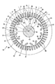
- FIG. 2 is a cross-sectional view of the rotary electric machine according to the first embodiment.
- FIG. 3 is a perspective view showing the first end surface side of the stator of the rotary electric machine.
- FIG. 4 is an enlarged perspective view showing a part of the coil end of the stator.
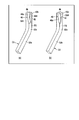
- FIG. 5 is a plan view showing coil segments constituting the stator coil.
- FIG. 6 is an enlarged cross-sectional view showing one slot of the stator.
- FIG. 7 is a perspective view showing an extended portion of the coil segment.
- FIG. 8 is a three-view view of the extension portion of the coil segment.
- FIG. 1 is a vertical sectional view showing a rotary electric machine according to the first embodiment.
- FIG. 2 is a cross-sectional view of the rotary electric machine according to the first embodiment.
- FIG. 3 is a perspective view showing the first end surface side of the stator of the
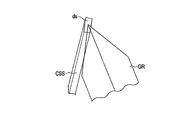
- FIG. 9 is a diagram schematically showing an example of an extended end portion of the coil segment and a grindstone for notch processing.
- FIG. 10 is a perspective view of a coil segment showing a state in which the joint ends of two coil segments adjacent to each other in the radial direction are engaged with each other.
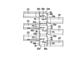
- FIG. 11 is a plan view showing a joint portion of coil segments arranged in the radial direction.
- FIG. 12 is a perspective view showing an extended end portion of the coil segment of the rotary electric machine according to the second embodiment.
- FIG. 13 is an enlarged perspective view showing a part of the coil end of the rotary electric machine according to the third embodiment.
- FIG. 14 is a perspective view showing an extended portion of the coil segment according to the third embodiment.
- FIG. 10 is a perspective view of a coil segment showing a state in which the joint ends of two coil segments adjacent to each other in the radial direction are engaged with each other.
- FIG. 11 is a plan view showing a joint portion of coil segments arranged in the
- FIG. 15 is a three-view view of the extension portion of the coil segment.
- FIG. 16 is a diagram schematically showing an extended end portion of the coil segment and a grindstone for notch processing.
- FIG. 17 is a perspective view of a coil segment showing a state in which the joint ends of two coil segments adjacent to each other in the radial direction are engaged with each other.
- FIG. 18 is a plan view showing joints of coil segments arranged in the radial direction in the rotary electric machine according to the fourth embodiment.
- FIG. 1 is a vertical cross-sectional view of the rotary electric machine according to the first embodiment, and shows only one half of the rotary electric machine with the central axis C1 as the center.
- FIG. 2 is a cross-sectional view of the rotary electric machine.
- the rotary electric machine 10 is configured as, for example, a permanent magnet type rotary electric machine.
- the rotary electric machine 10 includes an annular or cylindrical stator 12, a rotor 14 rotatably supported inside the stator 12 around the central axis C1 and coaxially supported with the stator 12, and these stators.
- a casing 30 that supports the rotor 12 and the rotor 14 is provided.
- the extending direction of the central axis C1 is referred to as an axial direction
- the direction of rotation around the central axis C1 is referred to as a circumferential direction
- the directions orthogonal to the axial direction and the circumferential direction are referred to as a radial direction.
- the stator 12 includes a cylindrical stator core 16 and a stator coil (hereinafter, coil) 18 mounted on the stator core 16.
- the stator core 16 is formed by laminating a large number of annular electromagnetic steel plates 17 made of a magnetic material, for example, silicon steel, in a concentric manner. A large number of electrical steel sheets 17 are connected to each other in a laminated state by welding a plurality of locations on the outer peripheral surface of the stator core 16.
- the stator core 16 has an inner peripheral surface coaxially located with the central axis C1, a first end surface 16a located at one end in the axial direction, and a second end surface 16b located at the other end in the axial direction.
- the first end surface 16a and the second end surface 16b extend orthogonally to the central axis C1.
- a plurality of slots 20 are formed in the inner peripheral portion of the stator core 16.
- the plurality of slots 20 are arranged at equal intervals in the circumferential direction.
- each slot 20 has an inner peripheral side end opened on the inner peripheral surface of the stator core 16.
- Each slot 20 extends in the radial direction (outward in the radial direction with respect to the central axis of the stator core 16) from the inner peripheral surface side of the stator core 16.
- Each slot 20 extends over the entire length of the stator core 16 in the axial direction.
- each slot 20 in the axial direction is open to the first end surface 16a, and the other end in the axial direction is open to the second end surface 16b.
- the inner peripheral end of each slot 20 may be configured so as not to open to the inner circumference of the stator core 16, and the inner peripheral surface of the stator core 16 may have a cylindrical surface shape.
- the inner peripheral portion of the stator core 16 constitutes a plurality of teeth 21 (for example, 48 in the present embodiment) protruding toward the central axis C1.
- the teeth 21 are arranged at equal intervals along the circumferential direction.
- the stator core 16 integrally has an annular yoke portion and a plurality of teeth 21 protruding in the radial direction from the inner peripheral surface of the yoke portion toward the central axis C1.
- a slot 20 is formed between two teeth 21 adjacent to each other in the circumferential direction.
- Coil 18 is mounted in a plurality of slots 20 and is wound around each tooth 21.
- the coil 18 is provided so as to have coil ends 18a and 18b extending outward in the axial direction from the first end surface 16a and the second end surface 16b of the stator core 16. By passing an alternating current through the coil 18, a predetermined interlinkage magnetic flux is formed in the stator 12 (teeth 21).
- the casing 30 has a substantially cylindrical first bracket 32a and a bowl-shaped second bracket 32b.
- the first and second brackets 32a and 32b are made of, for example, an aluminum alloy.
- the first bracket 32a is connected to the iron core retainer 26 located on the drive end side of the stator core 16.
- An annular bearing bracket 34 is coaxially fastened to the tip end side of the first bracket 32a with bolts.
- a first bearing housing 36 incorporating a roller bearing is fastened to the central portion of the bearing bracket 34.
- the second bracket 32b is connected to the iron core retainer 26 located on the opposite drive end side.
- a second bearing housing 38 having a built-in ball bearing is fastened to the central portion of the second bracket 32b.
- the rotor 14 includes a cylindrical shaft (rotating shaft) 43, a cylindrical rotor core 44 fixed to a substantially central portion in the axial direction of the shaft 43, and a plurality of rotor cores embedded in the rotor core 44. It has a permanent magnet 46 and. Both ends of the rotary shaft 43 in the axial direction are supported by the first bearing 35 and the second bearing 37, and are rotatably supported around the central axis C1.
- the rotor core 44 is configured as a laminated body in which a large number of magnetic materials, for example, a large number of annular electromagnetic steel plates 47 such as silicon steel are laminated concentrically.
- the rotor core 44 has an inner hole 48 formed coaxially with the central axis C1.
- the rotary shaft 43 is inserted and fitted into the inner hole 48 and extends coaxially with the rotor core 44.
- a substantially disk-shaped magnetic shielding plate 54 and a rotor core retainer 56 are provided at both ends of the rotor core 44 in the axial direction.
- the rotor core 44 is coaxially arranged with a slight gap (air gap) inside the stator core 16. That is, the outer peripheral surface of the rotor core 44 faces the inner peripheral surface (tip surface of the teeth 21) of the stator core 16 with a slight gap.
- the rotor core 44 is formed with a plurality of magnet embedding holes 50 that penetrate the rotor core 44 in the axial direction.
- a permanent magnet 46 is loaded and arranged in each magnet embedding hole 50, and is fixed to the rotor core 44 by, for example, an adhesive or the like. Each permanent magnet 46 extends over the entire length of the rotor core 44. Further, the plurality of permanent magnets 46 are arranged at predetermined intervals in the circumferential direction of the rotor core 44.
- the rotor core 44 has a d-axis extending in the radial or radial direction of the rotor core 44, and a q-axis electrically separated from the d-axis by 90 ° in the circumferential direction.
- the axis extending in the radial direction through the boundary between adjacent magnetic poles and the central axis C1 is defined as the q-axis
- the direction electrically perpendicular to the q-axis is defined as the d-axis.
- the d-axis and the q-axis are provided alternately in the circumferential direction of the rotor core 44 and in a predetermined phase.
- Two magnet embedding holes 50 are formed on both sides of each d-axis in the circumferential direction of the rotor core 44, and permanent magnets 46 are loaded in these embedding holes 50.
- Each of the embedded holes 50 and the permanent magnets 46 has a substantially rectangular cross-sectional shape and is inclined with respect to the d-axis. When viewed in a plane orthogonal to the central axis C1 of the rotor core 44, the two embedding holes 50 and the permanent magnets 46 are arranged side by side in a substantially V shape that opens toward the outer circumference, for example.
- the two permanent magnets 46 located on both sides of the d-axis circumferential direction are arranged so that the magnetization directions are opposite to each other in the circumferential direction of the rotor core 44, and the two permanent magnets 46 are located on both sides of the q-axis circumferential direction.
- the permanent magnets 46 are arranged so that the magnetization directions are the same.
- the rotary electric machine 10 has 8-pole (4-pole pair), 48 slots in which the front and back sides of the north and south poles of the permanent magnets 46 are alternately arranged for each adjacent magnetic pole, and is a single-layer distributed winding. It constitutes a wound permanent magnet embedded type rotary electric machine.
- FIG. 3 is a perspective view showing the second end surface side of the stator
- FIG. 4 is a perspective view showing a part of the coil end of the stator coil in an enlarged manner
- FIG. 5 is a perspective view showing an example of a coil segment.
- the coil 18 is configured by using, for example, a plurality of coil segments CS made of a flat conductor (flat wire) as a linear conductor, and is assembled to a stator core 16. As shown in FIG. 5, the coil segment CS is formed into a substantially U shape by cutting and bending a flat wire.
- the coil segment CS integrally has a pair of straight-line parts CSS facing each other at intervals and a cross-linking part CSB connecting one ends of the straight-line parts CSS.
- the coil segment CS has a substantially rectangular cross section (cross section) perpendicular to the longitudinal direction. That is, the cross section has a pair of long sides L1 facing each other and a pair of short sides S1 facing each other (see FIG. 6).
- the outer surface of the coil segment CS is covered with an insulating coating CL such as an insulating varnish.
- the extending end of each straight portion CSS is cut in a direction orthogonal to the longitudinal direction to form a rectangular tip surface (joint surface) dS substantially orthogonal to the longitudinal direction.
- a notch 40 is formed at one corner portion.
- the notch 40 opens at the corners to the two intersecting side surfaces and the joint surface ds.
- the inner surface (first engaging surface and the second engaging surface) and the joint surface ds of the notch 40 are not covered with an insulating coating, and form a conductive portion capable of conducting.
- the remaining portion of the joint end portion forms a hook-shaped portion (hook) 42 having a joint surface ds, a first engagement surface 40b, and a first facing surface FS, which will be described later. doing.
- the detailed shape and configuration of the notch 40 and the hook shape portion 42 will be described later.
- the four corners do not have to be right angles and may be chamfered or rounded.
- the portion connecting the ends of the two long sides facing each other in the cross section may be curved, for example, in an oval shape.
- the conductor is not limited to a flat conductor, and a conductor having a circular or elliptical cross section can be used.
- a pair of linear portion CSSs are inserted into different slots 20 from the first end surface 16a side of the stator core 16, for example, and the stator core 16 has a pair of straight portions CSS. It protrudes from the second end surface 16b by a predetermined length.
- Each straight line portion CSS forms an insertion portion arranged in the slot 20 and an extension portion CE extending from the slot 20 to the outside of the stator core 16.
- FIG. 6 is a cross-sectional view of one slot of the stator core 16.
- the linear portion CSS of the six coil segments CS is inserted into one slot 20.
- the six straight line portions CSS are arranged side by side in the radial direction of the stator core 16.
- the six straight line portions CSS are arranged in the slot 20 with the long sides L1 facing each other in parallel.
- An insulating material for example, an insulating paper P is wound around the outer surface of the six straight portion CSS, and the straight portion CSS is inserted into the slot 20 together with the insulating paper P.
- the insulating paper P may be inserted into the slot 20 in advance, and the coil 18 may be inserted with the insulating paper P arranged in the slot 20.
- the insulating paper P electrically insulates the coil 18 from the outside and physically protects the coil 18.
- the cross-linked portion CSB of the coil segment CS is arranged outside the stator core 16 and faces the first end surface 16a of the stator core 16 with a slight gap.
- the cross-linking portion CSB extends substantially along the circumferential direction of the stator core 16, and some cross-linking portions CSB extend intersecting with other cross-linking portions CSBs. These cross-linked portions CSB form a coil end 18a protruding from the first end surface 16a.
- the extension portion CE of the straight portion CSS protruding in the axial direction from the second end surface 16b is the circumferential direction of the stator core 16. It is bent in the direction of the axis and extends at an angle with respect to the axial direction. Further, the extending end portion of the extending portion CE is bent in the axial direction to form a second straight line portion extending in the axial direction. In this way, each extending portion CE is inclined with respect to the axial direction from the first bending portion (bending portion) 52a that bends at an angle in the circumferential direction from the axial direction of the stator core 16 and the first bending portion 52a.
- the extending portions CE of the six straight portions CSS inserted into each slot 20 are alternately bent in one direction and the opposite direction. That is, the extension portion CE located on the outermost circumference is bent in one direction in the circumferential direction of the stator core 16, and the extension portion CE located one inside is bent in the other direction (opposite direction) in the circumferential direction. There is. The extending portion CE on the inner side is bent in the one direction, and the extending portion CE on the inner side is bent in the opposite direction.
- the joint end portions 52d of the six extending portions CE extending from the plurality of different slots 20 are located substantially in a line in the radial direction of the stator core 16.
- joint surfaces ds are located at substantially the same height as the end surface 16b of the stator core 16 and are arranged in a row along the radial direction of the stator core 16. However, it extends almost in the same plane.
- Two joint end portions 52d adjacent to each other in the radial direction are engaged with each other and connected by engaging the hook-shaped portion 42 described above.
- the joint surfaces ds of the six joint ends 52d in each row are welded to each other by two (two each) and are mechanically and electrically joined.
- laser welding can be used.
- the two joint surfaces ds adjacent to each other in the radial direction are irradiated with laser light to partially melt the joint surface ds and the joint end portion 52d to form a weld bead WB straddling the two joint surfaces ds.
- Each weld or joint is covered with an insulating material such as powder coating or varnish.
- Three coils are formed by the plurality of coil segments CS joined to each other in this way.
- the extending portion CE of the coil segment CS constitutes a coil end 18b protruding from the second end surface 16b.
- a U-phase connection terminal TU, a V-phase connection terminal TV, and a W-phase connection terminal TW are connected to the three coils 18, respectively.
- FIG. 7 is a perspective view showing an extended portion of the coil segment
- FIG. 8 is a three-view view of the extended portion
- FIG. 9 is a diagram schematically showing an extended end portion of the coil segment and an example of a grindstone for notch processing.
- FIG. 10 is a perspective view showing two connected extension portions
- FIG. 11 is a plan view showing six extension portions connected by two.
- each of the extending portions CE of the coil segment CS has a first bent portion 52a curved in the circumferential direction of the stator core 16 and an axial direction from the first bent portion 52a to the stator core.
- An inclined portion 52b that is inclined and extends, a second bent portion 52c that bends in the axial direction from the extending end of the inclined portion 52b, and a linear extension from the second bent portion 52c in the axial direction of the stator core 16. It integrally has a second straight portion (joint end portion) 52d that has been put out. The tip surface of the joint end portion 52d forms the joint surface ds.
- One corner of the joint end 52d is cut to form a notch 40.
- the hook-shaped portion (hook) 42 is formed by the remaining portion of the joint end portion 52d.
- the notch 40 is opened in the first facing surface FS of the joint end portion 52d (the side surface facing the other joint end portion 52d), the other side surface intersecting with the first facing surface FS, and the joint surface ds. It is formed.
- the notch 40 has a first engaging surface 40b and a second engaging surface 40a extending from the middle portion of the joint end portion 52d in the longitudinal direction to the joint surface ds, respectively, and these first engaging surfaces 40b and the second engaging surface 40a.
- the mating surfaces 40a intersect each other so as to form an opening angle ⁇ of 90 ° or less.
- the first engaging surface 40b forming a part of the hook-shaped portion 42 extends from the central portion in the width direction of the joint surface ds to the first facing surface FS so as to be inclined with respect to the width direction of the joint end portion 52d. ..
- the second engaging surface 40a faces the other joining end portion 52d to be joined, and is inclined from the first facing surface FS to the central axis side 3 of the joining end portion 52d.
- the first engaging surface 40b extends along one side edge of the second engaging surface 40a from the central portion of the joint surface ds in the longitudinal direction to the middle portion of the first facing surface FS.
- the first engaging surface 40b faces the first bending portion 52a of the extending portion CE, that is, faces in a direction substantially opposite to the bending direction of the first bending portion 52a.
- the angle formed by the first engaging surface 40b and the second engaging surface 40a is set to 90 ° or less.
- the second engagement surface 40a extends in the longitudinal direction of the joint surface ds
- the first engagement surface 40b is in the width direction of the joint surface ds (diameter direction of the stator core) or in the width direction.
- the notch 40 and the hook-shaped portion 42 described above are formed by, for example, partially grinding the extending end portion of the straight portion CSS with a V-shaped grindstone GR. can do.
- two joint end portions 52d adjacent to each other in the radial direction are engaged with each other and connected by engaging the hook-shaped portions 42 with each other. That is, the hook-shaped portion 42 of one joint end portion 52d is engaged with the notch 40 of the other joint end portion 52d.
- the first engaging surface 40b of one hook-shaped portion 42 faces and abuts on the first engaging surface 40b of the other hook-shaped portion 42, and the first facing surface FS of one hook-shaped portion 42 faces and abuts on the other joint end. It faces and engages with the second engaging surface 40a of the portion 52d.
- the two hook-shaped portions 42 are urged in the direction in which the first engaging surfaces 40b mesh with each other (contact) by the restoring force (spring back) generated after the bending molding of the first bending portion 52a.
- the joint end portions 52d of the two extension portions CE are firmly connected to each other, and the first engaging surfaces 40b are brought into close contact with each other with almost no gap.
- the joint surface ds of one joint end portion 52d and the joint surface ds of the other joint end portion 52d are lined up flush with each other with almost no gap.
- the joint surfaces ds and the first engagement surfaces 40b are welded, that is, joined by irradiating the vicinity of the boundary of the first engagement surface 40b on the joint surface ds with a laser beam.
- the two joint ends 52d can be connected without a gap, it is not necessary to hold the two joint ends with a jig or the like having high accuracy and rigidity at the time of welding, and the manufacturability of the stator Is improved.
- each hook shape portion 42 is pressed against the inclined second engaging surface 40a of the other joint end portion 52d, so that the two joint end portions 52d are separated from each other by the joint end portion 52d.
- the two joint end portions 52d are separated from each other by the joint end portion 52d.
- a gap can be provided between the three sets of joint ends arranged in the radial direction, and the insulating property between them can be improved.
- bending of the joint end portion for providing such a gap becomes unnecessary, and the manufacturability of the stator is further improved.
- the flat wire insulating coating CL is in a conductive state by removing only the joint surface ds, the first engagement surface 40b and the second engagement surface 40a of the notch 40, but the joint end.
- the periphery of the portion 52d and the first facing surface FS are covered with an insulating coating CL.
- the insulating coating CL remains in the vicinity of the welded portion in this way, heat diffusion is hindered during welding, so that welding with an inexpensive low-power laser becomes possible. Further, the external force such as vibration is reduced from being directly applied to the welded portion, and the reliability of welding is improved. From the above, according to the present embodiment, a stator of a rotary electric machine capable of reducing manufacturing cost and improving manufacturability can be obtained.
- stator of the rotary electric machine will be described.
- same parts as those in the first embodiment described above are designated by the same reference numerals to omit or simplify the detailed description thereof, and parts different from those in the first embodiment. Will be explained in detail.
- FIG. 12 is a perspective view showing an extended portion of the coil segment of the stator according to the second embodiment.
- the hook-shaped portion 42 formed on one of the joint end portions 52d is the first.
- the engaging surface 40b has a plurality of inclined surfaces that are bent so that the central portion in the axial direction is convex in the direction intersecting the axial direction. That is, the first engaging surface 40b is a first inclined surface inclined from the joint surface ds toward the base end side toward the first bent portion 52a side, and a first bent portion from the first inclined surface to the base end of the notch 40.
- the first engaging surface 40b is concave in the direction in which the central portion in the axial direction intersects the axial direction. It is bent to. That is, the first engaging surface 40b is a first inclined surface inclined in the direction opposite to the first bent portion 52a from the joint surface ds toward the base end side, and the first inclined surface from the first inclined surface to the base end of the notch 40. It has a second inclined surface that is inclined toward the bent portion 52a side.
- the two joint end portions 52d and the hook shape portion 42 are connected to each other, the two joint end portions are caused by the restoring force (springback) generated after the bending molding of the first bending portion 52a, as in the first embodiment described above.
- the 52d is urged in a direction in which the first engaging surfaces 40b mesh with each other.
- the two joint end portions 52d are firmly connected to each other, and the first engaging surfaces 40b are brought into close contact with each other with almost no gap.
- the convexly bent first engaging surface 40b and the concavely bent first engaging surface 40b abut and fit with each other, so that the two joint end portions 52d are in the axial direction (vertical direction).
- Displacement is regulated and positioned at a predetermined height position. Thereby, the heights of the joint surfaces ds of the two joint end portions 52d can be made uniform. By aligning the heights of the joint surfaces ds, laser welding can be performed more easily and reliably.
- FIG. 13 is an enlarged perspective view showing a part of the coil end of the stator according to the third embodiment
- FIG. 14 is a perspective view showing an extended portion of the coil segment of the stator according to the third embodiment
- 15 is a three-view view of the extension portion
- FIG. 16 is a diagram schematically showing an example of an extension end portion of a coil segment and a grindstone for notch processing
- FIG. 17 is a diagram showing two adjacent coils in the radial direction. It is a perspective view which shows the state in which the extension part of is engaged and connected.
- the tip of each extending portion CE of the coil segment CS is cut obliquely with respect to the longitudinal direction.
- the extending portion CE has a joint surface (tip surface) ds inclined with respect to the longitudinal direction.
- the extending portion CE protruding from the second end surface 16b is from the first bending portion 52a and the first bending portion 52a that bend in the circumferential direction from the axial direction of the stator core 16. It has an inclined portion 52b that is inclined with respect to the axial direction and extends linearly, and a joint surface ds formed at the extending end of the inclined portion 52b.
- the first bent portion 52a is bent so that the joint surface ds is located substantially parallel to the second end surface 16b of the stator core 16.
- the tip of the inclined portion 52b constitutes the joint end portion.
- the extending portions CE of the six straight portions CSS inserted into each slot 20 are alternately bent in one direction and the opposite direction. That is, the extension portion CE located on the outermost circumference is bent in one direction in the circumferential direction of the stator core 16, and the extension portion CE located one inside is bent in the other direction (opposite direction) in the circumferential direction. Has been done.
- the extending portion CE on the inner side is bent in the one direction, and the extending portion CE on the inner side is bent in the opposite direction.
- the tip surfaces of the six extending portions CE extending from the plurality of different slots 20, that is, the joint surfaces ds, are located substantially in a line along the radial direction of the stator core 16 and are substantially in the same plane. It is postponed.
- a notch 40 and a hook-shaped portion 42 are formed at the joint end portion of the extension portion CE.
- the notch 40 is formed by partially cutting the first facing surface FS and the joint surface ds of the joint end portion.
- the notch 40 has a first engaging surface 40b and a second engaging surface 40a extending from a midway portion of the joint end portion 52d in the longitudinal direction to the joining surface ds, and these first engaging surface 40b and the second engaging surface 40a.
- the surfaces 40a intersect with each other so as to form an opening angle ⁇ of 90 ° or less.
- the second engaging surface 40a extends from the central portion of the joint surface ds in the width direction to the first facing surface FS so as to be inclined with respect to the axial direction of the extending portion CE.
- the second engaging surface 40a faces the other joining end portion to be joined, and is inclined from the first facing surface FS toward the central axis side of the extending portion CE.
- the first engaging surface 40b extends from the central portion of the joint surface ds in the longitudinal direction to the middle portion of the first facing surface FS.
- the first engaging surface 40b faces the first bending portion 52a of the extending portion CE, that is, faces in a direction substantially opposite to the bending direction of the first bending portion 52a.
- the angle formed by the second engaging surface 40a and the first engaging surface 40b is set to 90 ° or less.
- the second engagement surface 40a extends in the longitudinal direction of the joint surface ds
- the first engagement surface 40b is inclined toward the width direction of the joint surface ds or the first bending portion 52a side from the width direction. And is extending.
- the joint end portion of the extension portion CE has a claw-shaped hook-shaped portion (hook) having a joint surface ds, a first engagement surface 40b, and a first facing surface FS. 42 is formed.
- the above-mentioned notch 40 can be formed by, for example, grinding the extending end portion of the straight portion CSS with a V-shaped grindstone GR.
- the joint ends of two radially adjacent extension CEs are engaged and connected to each other by engaging the hook-shaped portions 42 with each other. That is, the hook-shaped portion 42 of one joint end is engaged with the notch 40 of the other joint end.
- the first engaging surface 40b of one hook-shaped portion 42 faces and abuts on the first engaging surface 40b of the other hook-shaped portion 42, and the first facing surface FS of one hook-shaped portion 42 faces and abuts on the other joint end. It faces and engages with the second engaging surface 40a of the portion.
- the two joint end portions are urged in the direction in which the first engaging surfaces 40b mesh with each other by the restoring force (spring back) generated after the bending molding of the first bending portion 52a.
- the joint ends of the two extending portions CE are firmly connected to each other, and the first engaging surfaces 40b are brought into close contact with each other with almost no gap.
- the joint surface ds of one joint end portion and the joint surface ds of the other joint end portion are located at substantially the same height and are lined up flush with each other with almost no gap.
- the joint surfaces ds and the first engagement surfaces 40b are welded and joined by irradiating the vicinity of the boundary of the first engagement surface 40b on the joint surface ds with a laser beam.
- the two joint ends of the coil segment can be connected without a gap, it is not necessary to hold the two joint ends with a high-precision and highly rigid jig or the like during welding, and the manufacturability is improved. improves.
- the same effects as those in the first embodiment described above can be obtained.
- the extension portion CE of the coil segment does not have the second straight portion, the height of the coil end can be reduced and the stator can be miniaturized.
- FIG. 18 is a plan view showing joints of coil segments arranged in the radial direction in the rotary electric machine according to the fourth embodiment.
- the second engaging surface 40a of each notch 40 provided at the joint end portion 52d of the coil segment is formed so as to have a small inclination angle with respect to the axial direction, or is substantially parallel to the axial direction. Is formed in.
- the two joint end portions 52d adjacent to each other in the radial direction are engaged with each other and joined by engaging the hook-shaped portions 42 with each other.
- the first engaging surface 40b of one hook-shaped portion 42 faces and is in contact with the first engaging surface 40b of the other hook-shaped portion 42.
- the two joint end portions 52d are urged in the direction in which the first engaging surfaces 40b mesh with each other, and the first engaging surfaces 40b are brought into close contact with each other with almost no gap.
- the first facing surface FS of one hook-shaped portion 42 faces the second engaging surface 40a of the other joint end portion 52d with a gap.
- the joint surface ds of one joint end portion 52d and the joint surface ds of the other joint end portion 52d are lined up flush with each other at the portion of the first engaging surface 40b without any gap.
- the joint surfaces ds and the first engagement surfaces 40b are welded to each other by irradiating a laser beam near the boundary of the first engagement surface 40b on the joint surface ds. In this way, there may be a gap between the second engaging surface 40a and the first facing surface FS, and if the first engaging surfaces 40b are closely joined to each other, a stable joining portion is formed. can do.
Landscapes
- Engineering & Computer Science (AREA)
- Power Engineering (AREA)
- Manufacturing & Machinery (AREA)
- Windings For Motors And Generators (AREA)
- Manufacture Of Motors, Generators (AREA)
- Iron Core Of Rotating Electric Machines (AREA)
Priority Applications (4)
| Application Number | Priority Date | Filing Date | Title |
|---|---|---|---|
| PCT/JP2020/009488 WO2021176662A1 (ja) | 2020-03-05 | 2020-03-05 | 固定子 |
| CN202080095641.3A CN115066824A (zh) | 2020-03-05 | 2020-03-05 | 定子 |
| JP2022504892A JP7146137B2 (ja) | 2020-03-05 | 2020-03-05 | 固定子 |
| US17/929,725 US12176776B2 (en) | 2020-03-05 | 2022-09-05 | Stator including coil segments with hook-shaped portions |
Applications Claiming Priority (1)
| Application Number | Priority Date | Filing Date | Title |
|---|---|---|---|
| PCT/JP2020/009488 WO2021176662A1 (ja) | 2020-03-05 | 2020-03-05 | 固定子 |
Related Child Applications (1)
| Application Number | Title | Priority Date | Filing Date |
|---|---|---|---|
| US17/929,725 Continuation US12176776B2 (en) | 2020-03-05 | 2022-09-05 | Stator including coil segments with hook-shaped portions |
Publications (1)
| Publication Number | Publication Date |
|---|---|
| WO2021176662A1 true WO2021176662A1 (ja) | 2021-09-10 |
Family
ID=77613208
Family Applications (1)
| Application Number | Title | Priority Date | Filing Date |
|---|---|---|---|
| PCT/JP2020/009488 Ceased WO2021176662A1 (ja) | 2020-03-05 | 2020-03-05 | 固定子 |
Country Status (4)
| Country | Link |
|---|---|
| US (1) | US12176776B2 (https=) |
| JP (1) | JP7146137B2 (https=) |
| CN (1) | CN115066824A (https=) |
| WO (1) | WO2021176662A1 (https=) |
Families Citing this family (3)
| Publication number | Priority date | Publication date | Assignee | Title |
|---|---|---|---|---|
| JP7495883B2 (ja) * | 2018-11-09 | 2024-06-05 | 株式会社アイシン | 電機子および電機子の製造方法 |
| JP7799990B2 (ja) * | 2021-04-13 | 2026-01-16 | 日産自動車株式会社 | 平角線モータコイル及び平角線モータコイルの製造方法 |
| JP7571747B2 (ja) * | 2022-02-18 | 2024-10-23 | トヨタ自動車株式会社 | 回転電機のステータ |
Citations (4)
| Publication number | Priority date | Publication date | Assignee | Title |
|---|---|---|---|---|
| JP2011229367A (ja) * | 2010-03-31 | 2011-11-10 | Denso Corp | 回転電機の固定子 |
| JP2015109718A (ja) * | 2013-12-03 | 2015-06-11 | トヨタ自動車株式会社 | 回転電機のコイル |
| WO2019059295A1 (ja) * | 2017-09-20 | 2019-03-28 | アイシン・エィ・ダブリュ株式会社 | 回転電機用電機子の製造方法 |
| JP2019161822A (ja) * | 2018-03-12 | 2019-09-19 | 本田技研工業株式会社 | 回転電機のステータ |
Family Cites Families (12)
| Publication number | Priority date | Publication date | Assignee | Title |
|---|---|---|---|---|
| CN100440687C (zh) * | 2002-10-11 | 2008-12-03 | 三菱电机株式会社 | 车辆用交流发电机的定子及其制造方法 |
| CN101024955B (zh) * | 2002-10-31 | 2010-05-26 | 住友金属工业株式会社 | 钢板桩 |
| JP4662141B2 (ja) | 2005-07-28 | 2011-03-30 | 株式会社デンソー | 固定子を含む回転電機 |
| JP5237048B2 (ja) * | 2008-02-13 | 2013-07-17 | 日立オートモティブシステムズ株式会社 | 回転電機、および固定子巻線 |
| KR101998419B1 (ko) * | 2012-12-26 | 2019-07-09 | 현대모비스 주식회사 | 헤어핀 및 이를 구비한 헤어핀 권선모터 |
| JP2015126643A (ja) | 2013-12-27 | 2015-07-06 | 日立オートモティブシステムズ株式会社 | 導線端末の接続方法 |
| JP6432532B2 (ja) * | 2016-01-13 | 2018-12-05 | トヨタ自動車株式会社 | ステータ |
| JP6609596B2 (ja) | 2017-07-10 | 2019-11-20 | 本田技研工業株式会社 | 回転電機のステータ |
| CN109586444B (zh) * | 2017-09-29 | 2020-10-23 | 比亚迪股份有限公司 | 定子组件及具有其的电机 |
| JP6663942B2 (ja) * | 2018-02-20 | 2020-03-13 | 本田技研工業株式会社 | 回転電機のステータ |
| JP2020114062A (ja) * | 2019-01-09 | 2020-07-27 | 三菱電機株式会社 | 回転電機の固定子およびその製造方法 |
| JP2020141528A (ja) * | 2019-02-28 | 2020-09-03 | 日本電産株式会社 | コイル接合方法、ステータ、それを備えたモータ及びそのモータを搭載した車両 |
-
2020
- 2020-03-05 JP JP2022504892A patent/JP7146137B2/ja active Active
- 2020-03-05 CN CN202080095641.3A patent/CN115066824A/zh active Pending
- 2020-03-05 WO PCT/JP2020/009488 patent/WO2021176662A1/ja not_active Ceased
-
2022
- 2022-09-05 US US17/929,725 patent/US12176776B2/en active Active
Patent Citations (4)
| Publication number | Priority date | Publication date | Assignee | Title |
|---|---|---|---|---|
| JP2011229367A (ja) * | 2010-03-31 | 2011-11-10 | Denso Corp | 回転電機の固定子 |
| JP2015109718A (ja) * | 2013-12-03 | 2015-06-11 | トヨタ自動車株式会社 | 回転電機のコイル |
| WO2019059295A1 (ja) * | 2017-09-20 | 2019-03-28 | アイシン・エィ・ダブリュ株式会社 | 回転電機用電機子の製造方法 |
| JP2019161822A (ja) * | 2018-03-12 | 2019-09-19 | 本田技研工業株式会社 | 回転電機のステータ |
Also Published As
| Publication number | Publication date |
|---|---|
| US12176776B2 (en) | 2024-12-24 |
| JP7146137B2 (ja) | 2022-10-03 |
| CN115066824A (zh) | 2022-09-16 |
| JPWO2021176662A1 (https=) | 2021-09-10 |
| US20220416605A1 (en) | 2022-12-29 |
Similar Documents
| Publication | Publication Date | Title |
|---|---|---|
| CN108463939B (zh) | 无刷电动机的定子、无刷电动机以及无刷电动机的定子的制造方法 | |
| JP6606311B1 (ja) | 固定子の製造方法 | |
| JP6848132B1 (ja) | 回転電機の固定子 | |
| JP7286805B2 (ja) | 固定子および回転電機 | |
| US12176776B2 (en) | Stator including coil segments with hook-shaped portions | |
| JP6461381B2 (ja) | 回転電機の固定子、回転電機、および、回転電機の固定子の製造方法 | |
| CN113544945B (zh) | 定子 | |
| JP2017112749A (ja) | ステータの組立方法およびステータ | |
| JP4002451B2 (ja) | 回転電機 | |
| JP2014011901A (ja) | ステータ、モータおよびステータの製造方法 | |
| JP2012105371A (ja) | 外転型の電動機 | |
| CN108781006B (zh) | 旋转电机、旋转电机的制造方法 | |
| JP6080964B2 (ja) | 回転電機の固定子 | |
| CN101032064B (zh) | 电枢、旋转电机、直流电动机以及无刷电动机 | |
| JP2017225208A (ja) | 電機子、回転電機および電機子の製造方法 | |
| JP6429400B2 (ja) | ステータコア、ステータ及び回転電機 | |
| WO2014157621A1 (ja) | ステータの構造 | |
| JP5256835B2 (ja) | 回転電機の固定子及び回転電機 | |
| US12062958B2 (en) | Armature | |
| JP2010239680A (ja) | 回転電機用電機子及びその製造方法 | |
| JP2025019387A (ja) | ロータ、モータ、ロータの製造方法 | |
| JP2025083730A (ja) | 回転電機のステータ | |
| JP2023061074A (ja) | 埋込磁石型モータ | |
| WO2022107713A1 (ja) | モータ及びステータの製造方法 | |
| CN119234370A (zh) | 电动机、芯块和定子芯 |
Legal Events
| Date | Code | Title | Description |
|---|---|---|---|
| 121 | Ep: the epo has been informed by wipo that ep was designated in this application |
Ref document number: 20923138 Country of ref document: EP Kind code of ref document: A1 |
|
| DPE1 | Request for preliminary examination filed after expiration of 19th month from priority date (pct application filed from 20040101) | ||
| ENP | Entry into the national phase |
Ref document number: 2022504892 Country of ref document: JP Kind code of ref document: A |
|
| NENP | Non-entry into the national phase |
Ref country code: DE |
|
| 122 | Ep: pct application non-entry in european phase |
Ref document number: 20923138 Country of ref document: EP Kind code of ref document: A1 |