WO2021166446A1 - Appareil pour inspecter l'aspect d'une capsule - Google Patents
Appareil pour inspecter l'aspect d'une capsule Download PDFInfo
- Publication number
- WO2021166446A1 WO2021166446A1 PCT/JP2020/048657 JP2020048657W WO2021166446A1 WO 2021166446 A1 WO2021166446 A1 WO 2021166446A1 JP 2020048657 W JP2020048657 W JP 2020048657W WO 2021166446 A1 WO2021166446 A1 WO 2021166446A1
- Authority
- WO
- WIPO (PCT)
- Prior art keywords
- capsule
- imaging
- contact
- drum
- orientation
- Prior art date
Links
Images


Classifications
-
- B—PERFORMING OPERATIONS; TRANSPORTING
- B07—SEPARATING SOLIDS FROM SOLIDS; SORTING
- B07C—POSTAL SORTING; SORTING INDIVIDUAL ARTICLES, OR BULK MATERIAL FIT TO BE SORTED PIECE-MEAL, e.g. BY PICKING
- B07C5/00—Sorting according to a characteristic or feature of the articles or material being sorted, e.g. by control effected by devices which detect or measure such characteristic or feature; Sorting by manually actuated devices, e.g. switches
- B07C5/34—Sorting according to other particular properties
- B07C5/342—Sorting according to other particular properties according to optical properties, e.g. colour
-
- B—PERFORMING OPERATIONS; TRANSPORTING
- B07—SEPARATING SOLIDS FROM SOLIDS; SORTING
- B07C—POSTAL SORTING; SORTING INDIVIDUAL ARTICLES, OR BULK MATERIAL FIT TO BE SORTED PIECE-MEAL, e.g. BY PICKING
- B07C5/00—Sorting according to a characteristic or feature of the articles or material being sorted, e.g. by control effected by devices which detect or measure such characteristic or feature; Sorting by manually actuated devices, e.g. switches
- B07C5/36—Sorting apparatus characterised by the means used for distribution
-
- B—PERFORMING OPERATIONS; TRANSPORTING
- B65—CONVEYING; PACKING; STORING; HANDLING THIN OR FILAMENTARY MATERIAL
- B65G—TRANSPORT OR STORAGE DEVICES, e.g. CONVEYORS FOR LOADING OR TIPPING, SHOP CONVEYOR SYSTEMS OR PNEUMATIC TUBE CONVEYORS
- B65G47/00—Article or material-handling devices associated with conveyors; Methods employing such devices
- B65G47/74—Feeding, transfer, or discharging devices of particular kinds or types
- B65G47/84—Star-shaped wheels or devices having endless travelling belts or chains, the wheels or devices being equipped with article-engaging elements
-
- G—PHYSICS
- G01—MEASURING; TESTING
- G01N—INVESTIGATING OR ANALYSING MATERIALS BY DETERMINING THEIR CHEMICAL OR PHYSICAL PROPERTIES
- G01N21/00—Investigating or analysing materials by the use of optical means, i.e. using sub-millimetre waves, infrared, visible or ultraviolet light
- G01N21/84—Systems specially adapted for particular applications
- G01N21/85—Investigating moving fluids or granular solids
-
- G—PHYSICS
- G01—MEASURING; TESTING
- G01N—INVESTIGATING OR ANALYSING MATERIALS BY DETERMINING THEIR CHEMICAL OR PHYSICAL PROPERTIES
- G01N21/00—Investigating or analysing materials by the use of optical means, i.e. using sub-millimetre waves, infrared, visible or ultraviolet light
- G01N21/84—Systems specially adapted for particular applications
- G01N21/88—Investigating the presence of flaws or contamination
- G01N21/95—Investigating the presence of flaws or contamination characterised by the material or shape of the object to be examined
- G01N21/9508—Capsules; Tablets
-
- B—PERFORMING OPERATIONS; TRANSPORTING
- B65—CONVEYING; PACKING; STORING; HANDLING THIN OR FILAMENTARY MATERIAL
- B65G—TRANSPORT OR STORAGE DEVICES, e.g. CONVEYORS FOR LOADING OR TIPPING, SHOP CONVEYOR SYSTEMS OR PNEUMATIC TUBE CONVEYORS
- B65G47/00—Article or material-handling devices associated with conveyors; Methods employing such devices
- B65G47/22—Devices influencing the relative position or the attitude of articles during transit by conveyors
- B65G47/24—Devices influencing the relative position or the attitude of articles during transit by conveyors orientating the articles
- B65G47/248—Devices influencing the relative position or the attitude of articles during transit by conveyors orientating the articles by turning over or inverting them
- B65G47/252—Devices influencing the relative position or the attitude of articles during transit by conveyors orientating the articles by turning over or inverting them about an axis substantially perpendicular to the conveying direction
-
- B—PERFORMING OPERATIONS; TRANSPORTING
- B65—CONVEYING; PACKING; STORING; HANDLING THIN OR FILAMENTARY MATERIAL
- B65G—TRANSPORT OR STORAGE DEVICES, e.g. CONVEYORS FOR LOADING OR TIPPING, SHOP CONVEYOR SYSTEMS OR PNEUMATIC TUBE CONVEYORS
- B65G47/00—Article or material-handling devices associated with conveyors; Methods employing such devices
- B65G47/74—Feeding, transfer, or discharging devices of particular kinds or types
- B65G47/84—Star-shaped wheels or devices having endless travelling belts or chains, the wheels or devices being equipped with article-engaging elements
- B65G47/846—Star-shaped wheels or wheels equipped with article-engaging elements
Definitions
- the present invention relates to a capsule visual inspection device, and more particularly to a capsule visual inspection device including a cap and a body.
- the visual inspection device 50 includes a charging hopper 11, a supply hopper 12, a supply drum 13, a first directional control drum 14, a second directional control drum 15, an inspection drum 16, and an image pickup device 17. I have.
- the capsule charged into the charging hopper 11 is supplied from the supply hopper 12 to the supply drum 13, and is conveyed upright by the supply drum 13 toward the first direction-regulating drum 14.
- the first direction-regulating drum 14 and the second direction-regulating drum 15 supply the capsule to be conveyed to the inspection drum 16 after performing direction regulation so that the cap side faces a certain direction and rolls over. do.
- the inspection drum 16 includes a fixed inner cylinder 16a and an outer cylinder 16b that is rotatably attached to the outside of the inner cylinder 16a and is intermittently driven.
- the outer cylinder 16b is formed with a plurality of pockets 16c formed of through holes, and while holding the capsule housed in the pockets 16c by the outer peripheral surface of the inner cylinder 16a, it is conveyed to the imaging position of the imaging device 17.
- a rotation roller 16d that is exposed to the outside from the inner cylinder 16a and comes into contact with the capsule is provided, and when the capsule is conveyed to the imaging position, the outer cylinder 16b is temporarily moved. When stopped, the capsule rotates due to the rotation of the rotation roller 16d.
- the image pickup device 17 includes a line sensor camera 17a and a lighting device 17b, and the line sensor camera 17a takes an image while illuminating the entire circumference of the rotating capsule with the lighting device 17b.
- the captured image is judged to be good or bad by a good or bad judgment unit (not shown), and good and bad products are sorted and collected by a sorting device (shown) based on the judgment result.
- the conventional visual inspection device requires a first direction-regulating drum 14 and a second direction-regulating drum 15 for aligning the directions of the capsules so that the quality of the capsule imaged by the image pickup device 17 can be correctly determined. Therefore, not only the configuration becomes complicated, but also there is room for improvement in terms of maintenance such as parts replacement and cleaning.
- an object of the present invention is to provide a capsule visual inspection apparatus capable of easily performing a capsule visual inspection at low cost.
- the object of the present invention is a device for inspecting the appearance of a capsule in which a cap is externally fitted to a body, and a carrier for transporting a capsule housed in a housing unit and a transported capsule are brought into contact with each other in the storage unit.
- a contact body that rotates by friction, an imaging device that images a rotating capsule, and a determination device that determines the quality of the capsule based on the imaging data of the imaging device are provided, and the contact body has a gap in the accommodating portion.
- the determination device can determine the orientation of the capsule by comparing the axial center of the capsule included in the imaging data with the center of the imaging area of the imaging device.
- the contact body is made of a roller and the outer peripheral surface in contact with the capsule is formed flat.
- the capsule visual inspection apparatus of the present invention the capsule visual inspection can be easily performed at low cost.
- FIG. 3 schematically. It is a figure for demonstrating the appearance inspection method of the capsule by the apparatus shown in FIG. It is a figure which shows an example of the imaging data. It is a schematic block diagram of the conventional capsule visual inspection apparatus.
- FIG. 1 is a schematic configuration diagram of a capsule visual inspection device (hereinafter, simply referred to as “visual inspection device”) according to an embodiment of the present invention.
- the visual inspection device 1 shown in FIG. 1 includes a delivery drum 21 in place of the first directional control drum 14 and the second directional control drum 15 included in the conventional visual inspection device 50 shown in FIG. 7. Further, instead of the inspection drum 16 shown in FIG. 7, a new inspection drum 30 is provided. Since the other configurations of the visual inspection device 1 are the same as those of the conventional visual inspection device 50, the same reference numerals are given to the same components as the conventional visual inspection device 50 in the visual inspection device 1 shown in FIG.
- the visual inspection device 1 of the present embodiment is suitably used for inspecting a hard capsule capable of accommodating powdery or liquid chemicals, foods, etc. by externally fitting a cap on the body. can do.
- the delivery drum 21 is formed so that a plurality of accommodating pockets 21a are aligned in the axial direction and the circumferential direction of the outer peripheral surface.
- Each storage pocket 21a is formed horizontally so that the axial direction of the capsule to be stored (fitting direction of the body and the cap) is along the rotation axis direction of the delivery drum 21.
- the capsule supplied from the supply drum 13 is delivered to the storage pocket of the delivery drum 21 rotating in the direction indicated by the arrow in FIG. 1 in a sideways state, and is supplied to the inspection drum 30.
- compressed air is supplied from the supply side of the capsule and the capsule is supplied so that the capsule can be smoothly delivered between the drums. Vacuum suction may be performed on the supplied side.
- the delivery drum 21 does not need to align the directions of the capsules unlike the conventional first direction-regulating drum 14 and the second direction-regulating drum 15, the delivery drum 21 may be simply provided with the storage pocket 21a. Therefore, in the conventional visual inspection device 50, by replacing the first direction regulating drum 14 and the second direction regulating drum 15 with the delivery drum 21, the configuration can be simplified and the manufacturing cost can be reduced, and maintenance can be performed. Will also be easier.
- the capsule may be supplied to the inspection drum 30 by using a supply device capable of supplying the capsule in a state of lying down, so that the capsule is directly supplied from this supply device to the inspection drum 30.
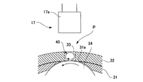
- FIG. 3 is an enlarged view of the inspection drum 30 shown in FIG.
- the inspection drum 30 includes a fixed cylindrical inner cylinder 31 and a cylindrical carrier 32 that is rotationally driven along the outer circumference of the inner cylinder 31.
- the transport body 32 includes an accommodating portion 33 composed of a plurality of through holes formed corresponding to the accommodating pockets 21a (see FIG. 2) of the delivery drum 21. Similar to the storage pocket 21a of the delivery drum 21, the storage portion 33 is formed in a horizontally long rectangular shape so that the axial direction of the capsule 40 to be stored is along the rotation axis direction of the transport body 32.
- the transport body 32 accommodates the capsule 40, which is transported from the delivery drum 21 along the guide plate 22 in a sideways state, in the accommodating portion 33 in the same posture, and the imaging position P is along the outer peripheral surface of the inner cylinder 31. Transport to.
- the size of the accommodating portion 33 is preferably such that a gap is formed between the inner wall of the accommodating portion 33 and the outer surface of the capsule 40 so that the capsule 40 can rotate inside, and particularly in the axial direction of the capsule 40. It is preferable to secure a gap sufficient to determine the movement of the capsule 40, which will be described later.
- the shape of the accommodating portion 33 is not particularly limited, and may be, for example, an oblong shape other than the rectangular shape.
- the inspection drum 30 further includes a contact body 34 that rotates the capsule 40 conveyed to the imaging position P by contact friction.
- the contact body 34 is composed of a roller that is rotationally driven independently of the transport body 32, and is arranged so that a flat outer peripheral surface is exposed to the outside through a window portion formed in the inner cylinder 31. Has been done.
- the line sensor camera 17a included in the image pickup device 17 shown in FIG. 1 takes an image of the capsule 40 conveyed to the image pickup device P shown in FIG. 3 and outputs the image pickup data to the determination device 20.
- the determination device 20 determines the quality of the capsule 40 based on the imaging data, and controls the injection of compressed air from the injection nozzle (not shown) according to the determination result, thereby using the capsule 40 as a non-defective product recovery chute 35. It can be sorted into the defective product collection can 36.
- the capsule 40 housed in the housing unit 33 is transported to the imaging position P by the intermittent drive of the transport body 32 and temporarily stopped. Then, the contact body 34 exposed through the window portion 31a of the inner cylinder 31 rotates in the direction indicated by the arrow, so that contact friction occurs between the contact body 34 and the lower portion of the capsule 40, and the capsule 40 becomes an arrow. Rotate in the axial direction shown.
- the line sensor camera 17a images the entire circumference of the capsule 40 by imaging the rotating capsule 40.
- the driving of the transport body 32 is restarted, and the next capsule 40 is transported to the imaging position P. In this way, the imaging data of the capsules 40 that are sequentially transported can be individually acquired.
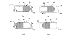
- the orientation of the capsule 40 housed in the storage unit 33 is random.
- FIG. 5A when the contact body 34 rotates in the direction of arrow A while the capsule 40 is housed in the housing portion 33 so that the body 41 is on the left side and the cap 42 is on the right side.
- the body 41 and the cap 42 come into contact with the contact body 34, and the capsule 40 rotates about the axial direction (around the fitting direction of the body 41 and the cap 42) as shown by arrow B. Since the outer diameter of the body 41 is smaller than the outer diameter of the cap 42, the rotating capsule 40 moves to the left side (body 41 side) in the accommodating portion 33 as shown by the arrow in FIG. 5 (b).
- the orientation of the capsule 40 can be correctly determined based on the position of the capsule 40.
- the cross-sectional shape of the portion where the body 41 and the cap 42 come into contact with the contact body 34 is preferably a circular shape, but may be an elliptical shape, a polygonal shape, or the like.
- the outer peripheral surface of the contact body 34 in contact with the capsule 40 is preferably formed flat so that it can be reliably contacted with both the body 41 and the cap 42 regardless of the orientation of the capsule 40. In order to ensure the contact between the capsule 40 and the contact body 34, it is preferable to vacuum-suck the inside of the inner cylinder 31 and suck the capsule 40 toward the contact body 34 side.
- FIG. 6 is a diagram showing an example of imaging data obtained by imaging the entire circumference of the capsule 40.
- the capsule 40 is housed in the accommodating portion 33 (see FIG. 5A) so that the body 41 is on the left side and the cap 42 is on the right side, the capsule 40 is on the left side.
- the center line C2 (broken line) passing through the center in the axial direction (horizontal direction in the figure) of the capsule 40 becomes the left side with respect to the center line C1 (dashed line) passing through the center of the imaging area.
- FIG. 6B when the capsule 40 is housed in the accommodating portion 33 (see FIG.
- the capsule 40 Moves to the right, so that the center line C2 (broken line) passing through the center of the capsule 40 in the axial direction (horizontal direction in the figure) becomes the right side with respect to the center line C1 (dashed line) passing through the center of the imaging area. .. Since the center of the imaging area is always constant and the axial center of the capsule 40 can be calculated by extracting the image of the capsule 40 included in the image data, the positions of the centers can be compared. The position of the capsule in the accommodating portion 33 can be accurately grasped, and thus the orientation of the capsule 40 can be reliably determined.
- the method for determining the orientation of the capsule 40 is not limited to the above method.
- the boundary line between the body 41 and the cap 42 is set on the imaging area. It may be compared with the center line. It is also possible to determine the orientation of the capsule 40 by comparing the sizes of the margin portions M1 and M2 generated on both the left and right sides of the capsule 40 in the imaging data.
- the moving direction of the capsule 40 can be determined by installing sensors at both ends of the accommodating portion 33 and detecting the position of the capsule 40 in the accommodating portion 33 by these sensors. According to these methods, even when the colors of the body 41 and the cap 42 are the same or similar to each other, or when the body 41 and the cap 42 are not printed or the printed contents are the same or similar, the capsule is used. The orientation of 40 can be accurately determined.
- the determination device 20 determines the quality of the capsule included in the image data based on the orientation of the determined capsule. For example, when the inspection condition is set with the orientation of the capsule 40 on which the body 41 is on the left side, if the actual orientation of the capsule 40 is the same as the orientation assumed by the inspection condition, the inspection can be performed as it is, while the actual inspection condition can be performed. If the orientation of the capsule 40 is opposite to the orientation assumed by the inspection conditions, the inspection is performed after the imaging data is flipped horizontally. As a result, the inspection can be performed under the same inspection conditions regardless of the orientation of the capsule 40.
- the transport method of the capsule 40 by the transport body 32 is a rotary transport type, but a linear transport type or the like may be used.
- the contact body 34 of the present embodiment is a roller that rotates the capsule 40 by rotation, but the capsule 40 is rotated by a linear motion or a swing motion of a belt, a plate material, or the like that causes contact friction on the capsule 40. It may be a configuration.
Abstract
La présente invention concerne un appareil pour inspecter l'aspect d'une capsule (40) dans laquelle un capuchon (42) est fixé à l'extérieur sur un corps (41), dans lequel : l'appareil comprend un corps de transport qui transporte la capsule logée dans une partie de logement (33), un corps de contact (34) qui amène la capsule transportée (40) à tourner par friction de contact à l'intérieur de la partie de logement (33), un dispositif d'imagerie (17) qui capture des images de la capsule rotative (40), et un dispositif d'évaluation qui évalue, sur la base de données d'imagerie provenant du dispositif d'imagerie (17), si la capsule est satisfaisante; le corps de contact (34) amène la capsule (40), qui est logée dans la partie de logement (33) de façon à y créer un espace, à tourner autour de la direction axiale, en déplaçant ainsi la capsule (40) vers le côté corps (41) à l'intérieur de la partie de logement (33); et le dispositif d'évaluation évalue l'orientation de la capsule (40) sur la base de la position de la capsule (40) dans la partie de logement (33).
Priority Applications (4)
| Application Number | Priority Date | Filing Date | Title |
|---|---|---|---|
| KR1020227022055A KR20220136994A (ko) | 2020-02-17 | 2020-12-25 | 캡슐의 외관검사장치 |
| US17/797,079 US20230052070A1 (en) | 2020-02-17 | 2020-12-25 | Apparatus for inspecting appearance of capsule |
| JP2022501671A JPWO2021166446A1 (fr) | 2020-02-17 | 2020-12-25 | |
| CN202080096730.XA CN115135991A (zh) | 2020-02-17 | 2020-12-25 | 胶囊的外观检查装置 |
Applications Claiming Priority (2)
| Application Number | Priority Date | Filing Date | Title |
|---|---|---|---|
| JP2020024121 | 2020-02-17 | ||
| JP2020-024121 | 2020-02-17 |
Publications (1)
| Publication Number | Publication Date |
|---|---|
| WO2021166446A1 true WO2021166446A1 (fr) | 2021-08-26 |
Family
ID=77390642
Family Applications (1)
| Application Number | Title | Priority Date | Filing Date |
|---|---|---|---|
| PCT/JP2020/048657 WO2021166446A1 (fr) | 2020-02-17 | 2020-12-25 | Appareil pour inspecter l'aspect d'une capsule |
Country Status (5)
| Country | Link |
|---|---|
| US (1) | US20230052070A1 (fr) |
| JP (1) | JPWO2021166446A1 (fr) |
| KR (1) | KR20220136994A (fr) |
| CN (1) | CN115135991A (fr) |
| WO (1) | WO2021166446A1 (fr) |
Cited By (1)
| Publication number | Priority date | Publication date | Assignee | Title |
|---|---|---|---|---|
| JP7473249B2 (ja) | 2022-01-21 | 2024-04-23 | エス エル テイ ジイ コーポレーション | 医薬品カプセルの外観検査装置 |
Citations (6)
| Publication number | Priority date | Publication date | Assignee | Title |
|---|---|---|---|---|
| JPS5794381A (en) * | 1980-12-04 | 1982-06-11 | Morishita Pharma | Automatic selector for capsule |
| JPH01102749U (fr) * | 1988-09-08 | 1989-07-11 | ||
| JPH05149883A (ja) * | 1991-08-22 | 1993-06-15 | Ckd Corp | 錠剤シートの検査装置 |
| JPH0880475A (ja) * | 1994-05-14 | 1996-03-26 | Maschimpex Gmbh | 製薬工業、製菓工業等における小形製品を形態及び色に応じて分別する自動分別装置 |
| CN202494644U (zh) * | 2012-03-07 | 2012-10-17 | 北京大恒图像视觉有限公司 | 胶囊质量检测机 |
| US20170219497A1 (en) * | 2014-10-17 | 2017-08-03 | Yong-Kwan Shin | Hybrid inspection system and inspection method for dosage |
Family Cites Families (1)
| Publication number | Priority date | Publication date | Assignee | Title |
|---|---|---|---|---|
| JP3687710B2 (ja) | 1997-02-17 | 2005-08-24 | シオノギクオリカプス株式会社 | 固形製剤の外観検査装置 |
-
2020
- 2020-12-25 JP JP2022501671A patent/JPWO2021166446A1/ja active Pending
- 2020-12-25 KR KR1020227022055A patent/KR20220136994A/ko unknown
- 2020-12-25 WO PCT/JP2020/048657 patent/WO2021166446A1/fr active Application Filing
- 2020-12-25 CN CN202080096730.XA patent/CN115135991A/zh active Pending
- 2020-12-25 US US17/797,079 patent/US20230052070A1/en active Pending
Patent Citations (6)
| Publication number | Priority date | Publication date | Assignee | Title |
|---|---|---|---|---|
| JPS5794381A (en) * | 1980-12-04 | 1982-06-11 | Morishita Pharma | Automatic selector for capsule |
| JPH01102749U (fr) * | 1988-09-08 | 1989-07-11 | ||
| JPH05149883A (ja) * | 1991-08-22 | 1993-06-15 | Ckd Corp | 錠剤シートの検査装置 |
| JPH0880475A (ja) * | 1994-05-14 | 1996-03-26 | Maschimpex Gmbh | 製薬工業、製菓工業等における小形製品を形態及び色に応じて分別する自動分別装置 |
| CN202494644U (zh) * | 2012-03-07 | 2012-10-17 | 北京大恒图像视觉有限公司 | 胶囊质量检测机 |
| US20170219497A1 (en) * | 2014-10-17 | 2017-08-03 | Yong-Kwan Shin | Hybrid inspection system and inspection method for dosage |
Cited By (1)
| Publication number | Priority date | Publication date | Assignee | Title |
|---|---|---|---|---|
| JP7473249B2 (ja) | 2022-01-21 | 2024-04-23 | エス エル テイ ジイ コーポレーション | 医薬品カプセルの外観検査装置 |
Also Published As
| Publication number | Publication date |
|---|---|
| CN115135991A (zh) | 2022-09-30 |
| KR20220136994A (ko) | 2022-10-11 |
| US20230052070A1 (en) | 2023-02-16 |
| JPWO2021166446A1 (fr) | 2021-08-26 |
Similar Documents
| Publication | Publication Date | Title |
|---|---|---|
| KR100542477B1 (ko) | 고형 제제의 외관검사장치 | |
| JP4035679B2 (ja) | 錠剤の側面検査装置、及び表裏面検査装置、並びにこれらを用いた錠剤の外観検査装置 | |
| US6079284A (en) | Visual inspection apparatus for tablets | |
| JP3846532B2 (ja) | 錠剤の側面検査装置及び該側面検査装置を用いた錠剤の外観検査装置 | |
| JP2008008897A (ja) | 錠剤の表裏面外観検査装置、側面外観検査装置及び外観検査装置 | |
| WO2021166446A1 (fr) | Appareil pour inspecter l'aspect d'une capsule | |
| JP2009161260A (ja) | 錠剤の搬送装置、整列供給装置及び側面外観検査装置 | |
| JP4381723B2 (ja) | キャップの外観検査装置 | |
| JP2000097865A (ja) | 錠剤の外観検査装置 | |
| US7079236B2 (en) | Appearance inspection machine for flat tablet | |
| JPH10170446A (ja) | 錠剤の姿勢変換機構及び錠剤の外観検査装置 | |
| JP2977640B2 (ja) | カプセル検査装置 | |
| KR102257955B1 (ko) | 소형물품 외관 검사장치 | |
| JP7470538B2 (ja) | カプセル検査装置 | |
| JP7012802B2 (ja) | 錠剤に対する印刷及び検査を行う錠剤印刷及び検査装置ならびに方法 | |
| JP4853673B2 (ja) | 不良カプセルの除去機構 | |
| JP4633093B2 (ja) | 錠剤の表裏面検査装置及び外観検査装置 | |
| JPH11241999A (ja) | 偏平錠剤の側面検査装置及び該側面検査装置を具備した外観検査装置 | |
| JP5344907B2 (ja) | ビン検査装置 | |
| JP2005315698A (ja) | 缶体検査装置及び缶体検査方法 | |
| JP2022065679A (ja) | 検査装置 | |
| JPH11201904A (ja) | 偏平錠剤の側面検査装置及び該側面検査装置を具備した外観検査装置 | |
| JP2003252429A (ja) | 固形製剤の姿勢制御方法及びその装置 |
Legal Events
| Date | Code | Title | Description |
|---|---|---|---|
| 121 | Ep: the epo has been informed by wipo that ep was designated in this application |
Ref document number: 20919524 Country of ref document: EP Kind code of ref document: A1 |
|
| ENP | Entry into the national phase |
Ref document number: 2022501671 Country of ref document: JP Kind code of ref document: A |
|
| NENP | Non-entry into the national phase |
Ref country code: DE |
|
| 122 | Ep: pct application non-entry in european phase |
Ref document number: 20919524 Country of ref document: EP Kind code of ref document: A1 |