WO2021166049A1 - テープカッター - Google Patents
テープカッター Download PDFInfo
- Publication number
- WO2021166049A1 WO2021166049A1 PCT/JP2020/006128 JP2020006128W WO2021166049A1 WO 2021166049 A1 WO2021166049 A1 WO 2021166049A1 JP 2020006128 W JP2020006128 W JP 2020006128W WO 2021166049 A1 WO2021166049 A1 WO 2021166049A1
- Authority
- WO
- WIPO (PCT)
- Prior art keywords
- adhesive tape
- cutter
- tape
- blade
- posture
- Prior art date
- Legal status (The legal status is an assumption and is not a legal conclusion. Google has not performed a legal analysis and makes no representation as to the accuracy of the status listed.)
- Ceased
Links
Images








Classifications
-
- B—PERFORMING OPERATIONS; TRANSPORTING
- B26—HAND CUTTING TOOLS; CUTTING; SEVERING
- B26D—CUTTING; DETAILS COMMON TO MACHINES FOR PERFORATING, PUNCHING, CUTTING-OUT, STAMPING-OUT OR SEVERING
- B26D1/00—Cutting through work characterised by the nature or movement of the cutting member or particular materials not otherwise provided for; Apparatus or machines therefor; Cutting members therefor
- B26D1/01—Cutting through work characterised by the nature or movement of the cutting member or particular materials not otherwise provided for; Apparatus or machines therefor; Cutting members therefor involving a cutting member which does not travel with the work
- B26D1/02—Cutting through work characterised by the nature or movement of the cutting member or particular materials not otherwise provided for; Apparatus or machines therefor; Cutting members therefor involving a cutting member which does not travel with the work having a stationary cutting member
-
- B—PERFORMING OPERATIONS; TRANSPORTING
- B65—CONVEYING; PACKING; STORING; HANDLING THIN OR FILAMENTARY MATERIAL
- B65H—HANDLING THIN OR FILAMENTARY MATERIAL, e.g. SHEETS, WEBS, CABLES
- B65H35/00—Delivering articles from cutting or line-perforating machines; Article or web delivery apparatus incorporating cutting or line-perforating devices, e.g. adhesive tape dispensers
- B65H35/0006—Article or web delivery apparatus incorporating cutting or line-perforating devices
Definitions
- the present invention relates to a tape cutter.
- the conventional one had to be placed on a mounting surface such as a top plate when it was used, and it was not always possible to use it flexibly while being picked up by the user.
- the position of the cutter when used is excessively separated from the outer surface of the wound adhesive tape body, so that the adhesive tape has to be pulled out excessively from the wound adhesive tape body. It was.
- the present invention has been made by paying attention to the above circumstances, and at least provides a tape cutter having a compact posture when not in use and a structure which is easy to use while holding it in the hand when in use. It is in.
- the invention according to claim 1 is a tape cutter configured so that a blade capable of cutting the adhesive tape can be accommodated in a hollow portion of a wound adhesive tape body in which the adhesive tape is wound. It is a tape cutter provided with a movable body capable of moving the blade housed in the wound adhesive tape body to the vicinity of the outer surface of the wound adhesive tape body.
- the invention according to claim 2 is provided with a base body arranged in the hollow portion, and the movable body has a blade and is configured to be movable relative to the base body.
- Item 1 is the tape cutter.
- the movable body is connected to the base body via a first hinge portion and an intermediate member, and the movable body is connected to the intermediate member via a second hinge portion.
- the tape cutter according to claim 2 further comprising a cutter member having a blade.
- the cutter member extends in a direction in which a base end portion is connected to the second hinge portion and a blade is provided and the tip of the standing wall intersects the standing wall.
- the tape cutter according to claim 4 which is provided with a main wall that has been taken out.
- the invention according to claim 6 has a storage posture in which the movable body is housed in a storage space formed in the base body, and a cuttable posture in which the blade is positioned on the outer surface side of the wound adhesive tape body.
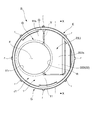
- FIG. 2 is a cross-sectional view taken along line XX in FIG.
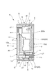
- FIG. 8 is a cross-sectional view taken along the line YY.
- the perspective view in the same embodiment. The perspective view in the same embodiment.
- the perspective view in the same embodiment. The perspective view which shows the other embodiment.
- the perspective view in the same embodiment. The perspective view in the same embodiment.
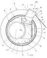
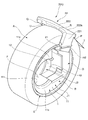
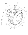
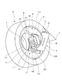
- FIGS. 1 to 15 show that the movable body 2 of the tape cutter B takes the accommodation posture (L). 7 to 12 and 14 show that the movable body 2 of the tape cutter B takes a cuttable posture (K).
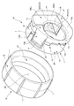
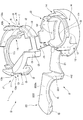
- FIG. 13 is a perspective view of a deployed state for explaining the structure of the cutter body D
- FIG. 15 shows a movable body 2 of the tape cutter B between the accommodation posture (L) and the cuttable posture (K). An example of a certain state is shown.
- the tape cutter B of this embodiment includes a movable body 2 provided with a blade P capable of taking an accommodation posture (L) and a cuttable posture (K).
- the tape cutter B is configured so that the blade P capable of cutting the adhesive tape T can be accommodated in the hollow portion C of the wound adhesive tape body A formed by winding the adhesive tape T in the accommodating posture (L). ..
- the wound adhesive tape body A is one without a winding core, that is, a coreless one.
- the adhesive tape T constituting the wound adhesive tape body A is, for example, a masking tape.
- the wound adhesive tape body A is formed by winding and laminating an adhesive tape T having a predetermined length so as to surround the hollow portion C in a state where a hollow portion C in which the adhesive tape T does not exist is provided in the central portion. It was done.
- the coreless wound adhesive tape body A has a substantially annular shape when viewed from the side.
- the width dimension of the wound adhesive tape body A is set to be substantially the same as the width dimension of the outer ring member E in the tape cutter B (for example, 15 mm).
- the wound adhesive tape body A is subjected to a so-called glue killing treatment on the inner peripheral surface n facing the hollow portion C.
- the "glue-killing treatment” is a known treatment for preventing the adhesive force of an adhesive (not shown) applied to the adhesive tape T from being exerted.
- a tape for preventing the adhesive from being exposed It is processed by imprinting or printing that can form a non-adhesive portion.
- the tape cutter B is supported by a cutter body D having a blade P and a cutter body D so as to be rotatable relative to the cutter body D, and an outer ring member E in which an outer peripheral portion G can engage with an inner peripheral surface n of the wound adhesive tape body A. It is equipped with.
- the cutter body D is provided with a communication hole F into which a user's finger can be inserted when the movable body 2 is moved or when the cutter body D is rotated with respect to the outer ring member E.
- a concave groove portion I that engages with a positioning convex rail portion e1 provided on the inner peripheral portion of the outer ring member E is formed on the outer peripheral portion H of the base body 1.
- the concave groove portion I has a guide bottom surface i3 that can engage with the protruding tip surface of the convex rail portion e1, and a pair of guide side surfaces that can engage with both outer surfaces of the convex rail portion e1, that is, the first guide side surface i1 and the second guide. It has a side surface i2.
- a storage space sp capable of accommodating the movable body 2 is formed in the base body 1.
- the first base body component J1 has a left outer surface 11s which is an outer surface on one side, and can form a communication hole F penetrating in the left-right direction in cooperation with the second base body component J2.
- the left outer wall portion 11 having the left communication hole constituent portion 11r and the outer peripheral portion H that can form the outer peripheral portion H that engages with the outer ring member E in cooperation with the second base body constituent portion J2, that is, the left peripheral wall portion 13. I have.
- the left peripheral wall portion 13 has a first guide side surface i1 capable of partially guiding one side surface of the convex rail portion e1, a second guide side surface i2 capable of guiding the other side surface of the convex rail portion e1, and a second guide surface i2. It is provided with a guide bottom surface i3 located between the first guide side surface i1 and the second guide side surface i2.
- the first guide side surface i1 is formed on the retaining protrusion 13b of the elastic claw 13a, which is an elastic engaging body provided on the left peripheral wall portion 13.
- the elastic claw 13a can be temporarily elastically deformed by being pressed by the convex rail portion e1 projecting from the inner peripheral surface of the outer ring member E. ing.
- the elastic claw 13a provided on the cutter body D prevents the cutter body D attached to the outer ring member E from detaching from the outer ring member E.
- the second base body component J2 has a right outer surface 12s which is an outer surface on the other side, and can form a communication hole F penetrating in the left-right direction in cooperation with the first base body component J1.
- the right outer wall portion 12 having the right communication hole component portion 12r and the other, that is, the right peripheral wall portion 14 capable of forming the outer peripheral portion H engaged with the outer ring member E in cooperation with the first base body component portion J1. I have.
- the movable body 2 is connected to the right outer wall portion 12 via the first hinge portion m1 which is a hinge portion. That is, a connecting portion with the movable body 2 is provided on the inner surface of the right outer wall portion 12.
- the movable body 2 has a storage posture (L) housed in the storage space sp formed in the base body 1 as shown in FIGS. 1 to 6, and is wound as shown in FIGS. 7 to 12 and 14. It is possible to take a cuttable posture (K) in which the blade P is positioned on the outer surface side of the adhesive tape body A.
- the movable body 2 is a cutter member having an intermediate member 21 connected to the base body 1 via the first hinge portion m1 and a blade P connected to the intermediate member 21 via the second hinge portion m2. It is equipped with 22.
- the first hinge portion m1 and the second hinge portion m2 are so-called resin hinges formed of a thin synthetic resin that can be flexibly deformed.
- the movable body 2 makes it possible to operate the intermediate member 21 and the cutter member 22 between the cuttable posture (K) and the accommodating posture (L) by using the first hinge portion m1 and the second hinge portion m2.
- the intermediate member 21 has a substantially rectangular plate shape, and the first hinge portion m1 and the second hinge portion m2 forming linear shapes are provided at the base end portion and the tip end portion, respectively, so that the blade P is wound. It is movable so as to be substantially parallel to the outer surface of the adhesive tape body A. For example, as shown in FIGS.
- the tape cutter B winds the blade P around the outer circumference of the wound adhesive tape body A regardless of the amount of the remaining amount of the adhesive tape T in the wound adhesive tape body A. It can be positioned so as to be substantially parallel to the surface.
- the intermediate member 21 has a plate shape, the base end portion is connected to the second base body constituent portion J2 of the base body 1 via the first hinge portion m1, and the tip end portion is connected via the second hinge portion m2. It is connected to the cutter member 22.
- the main wall 222 has a plate shape.
- the entire main wall 222 is located in the accommodation space sp, and the outer surface 222s of the main wall 222 is substantially flush with the left outer wall portion 11 of the base body 1. It can be positioned to make an eggplant.
- the standing wall 221 takes a posture along one of the wound adhesive tape bodies A, that is, near the left outer portion, and hits the wound adhesive tape body A.
- the cutter member 22 can be positioned at a position suitable for cutting the adhesive tape T.
- the outer ring member E has an annular shape in a side view in a form that can be fitted inward to the wound adhesive tape body A.
- the outer ring member E is engaged with the outer peripheral portion H of the base body 1 and is supported so as to be rotatable relative to the base body 1.
- the width dimension of the outer ring member E is set to be substantially the same as the width dimension of the cutter body D when the movable body 2 takes the accommodation posture (L) (for example, 15 mm) or larger than the width dimension of the cutter body D.
- the tape cutter B is internally fitted into the hollow portion C of the wound adhesive tape body A having a size corresponding to the tape cutter B.
- the tip portion st of the rib r projecting from the outer ring member E is pressed against the inner peripheral surface n of the wound adhesive tape body A, and the outer ring member E and the wound adhesive tape body A are connected so that they can rotate integrally.
- the intermediate member 21 Since the intermediate member 21 is connected to the base body 1 via the first hinge portion m1, it gradually rises from the left outer wall portion 11 as the cutter member 22 moves outward. Further, the cutter member 22 connected to the intermediate member 21 via the second hinge portion m2 gradually moves away from the base body 1 by the user's pull-out operation, and is at a predetermined position where the adhesive tape T can be cut, that is, winding adhesive. It will move to the outer surface side of the tape body A.
- the upright wall 221 of the cutter member 22 is located on the left side of the wound adhesive tape body A and is wound.
- the main wall 222 of the cutter member 22 is located on the outer peripheral surface side of the adhesive tape body A.
- the posture-maintaining protrusion U projecting downward from the main wall 222 is located on the right side surface side of the wound adhesive tape body A, and is engaged with respect to the right side surface portion of the wound adhesive tape body A. It has become a match.
- the cutter member 22 is provided on the main wall 222 with the upright wall 221 and the posture-maintaining protrusion U cooperating with each other and positioned with respect to the wound adhesive tape body A.
- the blade P is configured to be able to take a suitable posture for easily cutting the adhesive tape T.
- the drawn adhesive tape T is pulled toward the blade P of the cutter member 22 in the cuttable posture (K), so that the adhesive tape T is cut by the blade P.
- the movable body 2 When the process for cutting the adhesive tape T is completed, the movable body 2 is moved from the cuttable posture (K) to the accommodation posture (L) through the reverse procedure of the above-mentioned procedure. Finally, by engaging the engaging convex portion Q formed at the rear end portion of the cutter member 22 with the engaging concave portion V provided in the base body 1, the movable body 2 preferably has the accommodation posture (L). Will be retained.
- the wound adhesive tape body A when not in use, has a compact posture that does not overlap the outer surface and the outer peripheral surface of the wound adhesive tape body A and does not impair the appearance of the wound adhesive tape body A. It is possible to provide a tape cutter B having a structure that is easy to use while holding it in the hand at the time of use.
- the cutter member 22 has an upright wall 221 whose base end is connected to the second hinge portion m2, and a main wall 222 provided with a blade P and extending from the tip of the upright wall 221 in a direction intersecting the upright wall 221. It is equipped with. Therefore, by having the upright wall 221 and the main wall 222, the cutter member 22 can be suitably positioned with respect to the wound adhesive tape body A in order to cut the adhesive tape T.
- the movable body 2 has a storage posture (L) housed in the storage space sp formed in the base body 1 and a cuttable posture (K) in which the blade P is positioned on the outer peripheral surface side of the wound adhesive tape body A. Can be taken.
- the cutter body D which has a compact posture in the accommodation posture (L) and a suitable posture in which the adhesive tape T can be cut on the outer peripheral surface side of the wound adhesive tape body A in the cuttable posture (K). It has become possible.
- the tape cutter B is arranged in the hollow portion C of the wound adhesive tape body A formed by winding the adhesive tape T, and has a blade P capable of cutting the adhesive tape T. It includes a cutter body D and an outer ring member E that is rotatably supported with respect to the cutter body D and whose outer peripheral portion G can engage with the inner peripheral surface n of the wound adhesive tape body A.
- the outer ring member E can rotate relative to the cutter body D in a state where the outer ring member E is appropriately positioned with respect to the cutter body D.
- the outer ring member E is set smaller than the width dimension of the cutter body D.
- the movable body may be provided with two or more hinge portions. Further, the movable body may be provided with a plurality of intermediate members having hinge portions arranged at both ends.
Landscapes
- Life Sciences & Earth Sciences (AREA)
- Forests & Forestry (AREA)
- Engineering & Computer Science (AREA)
- Mechanical Engineering (AREA)
- Adhesive Tape Dispensing Devices (AREA)
Priority Applications (3)
| Application Number | Priority Date | Filing Date | Title |
|---|---|---|---|
| PCT/JP2020/006128 WO2021166049A1 (ja) | 2020-02-17 | 2020-02-17 | テープカッター |
| CN202080096347.4A CN115087525B (zh) | 2020-02-17 | 2020-02-17 | 带切割器 |
| JP2022501419A JP7287565B2 (ja) | 2020-02-17 | 2020-02-17 | テープカッター |
Applications Claiming Priority (1)
| Application Number | Priority Date | Filing Date | Title |
|---|---|---|---|
| PCT/JP2020/006128 WO2021166049A1 (ja) | 2020-02-17 | 2020-02-17 | テープカッター |
Publications (1)
| Publication Number | Publication Date |
|---|---|
| WO2021166049A1 true WO2021166049A1 (ja) | 2021-08-26 |
Family
ID=77390678
Family Applications (1)
| Application Number | Title | Priority Date | Filing Date |
|---|---|---|---|
| PCT/JP2020/006128 Ceased WO2021166049A1 (ja) | 2020-02-17 | 2020-02-17 | テープカッター |
Country Status (3)
| Country | Link |
|---|---|
| JP (1) | JP7287565B2 (https=) |
| CN (1) | CN115087525B (https=) |
| WO (1) | WO2021166049A1 (https=) |
Citations (2)
| Publication number | Priority date | Publication date | Assignee | Title |
|---|---|---|---|---|
| JPS3923600Y1 (https=) * | 1958-08-27 | 1964-08-14 | ||
| JPH0553887U (ja) * | 1991-12-27 | 1993-07-20 | 宗晴 南條 | 巻きテープ切断具 |
Family Cites Families (4)
| Publication number | Priority date | Publication date | Assignee | Title |
|---|---|---|---|---|
| KR100533838B1 (ko) * | 2004-04-30 | 2005-12-07 | 이상철 | 접착테이프용 디스펜서 |
| CN201343329Y (zh) * | 2008-06-20 | 2009-11-11 | 刘玉菁 | 胶带切割器 |
| JP3189212U (ja) * | 2013-12-18 | 2014-02-27 | エスコ株式会社 | テープカッターおよび切断カートリッジ |
| JP2017114587A (ja) * | 2015-12-21 | 2017-06-29 | スリーエム イノベイティブ プロパティズ カンパニー | テープホルダ |
-
2020
- 2020-02-17 JP JP2022501419A patent/JP7287565B2/ja active Active
- 2020-02-17 WO PCT/JP2020/006128 patent/WO2021166049A1/ja not_active Ceased
- 2020-02-17 CN CN202080096347.4A patent/CN115087525B/zh active Active
Patent Citations (2)
| Publication number | Priority date | Publication date | Assignee | Title |
|---|---|---|---|---|
| JPS3923600Y1 (https=) * | 1958-08-27 | 1964-08-14 | ||
| JPH0553887U (ja) * | 1991-12-27 | 1993-07-20 | 宗晴 南條 | 巻きテープ切断具 |
Also Published As
| Publication number | Publication date |
|---|---|
| JP7287565B2 (ja) | 2023-06-06 |
| JPWO2021166049A1 (https=) | 2021-08-26 |
| CN115087525B (zh) | 2023-11-24 |
| CN115087525A (zh) | 2022-09-20 |
Similar Documents
| Publication | Publication Date | Title |
|---|---|---|
| JP4228915B2 (ja) | スライド部材のロック構造及び転写具 | |
| CN102666331B (zh) | 胶带送出装置及胶带粘贴器 | |
| JP2005199631A (ja) | 転写具 | |
| US6896025B2 (en) | Adhesive tape adhering device | |
| JP2007532446A (ja) | 両面粘着テープディスペンサ | |
| WO2021166051A1 (ja) | テープカッター | |
| WO2021166049A1 (ja) | テープカッター | |
| JP2005193999A (ja) | 転写具 | |
| US20100101733A1 (en) | Desktop double-sided adhesive tape dispenser | |
| JP2007237327A (ja) | テープ切断用のカッター構造、該カッター構造を備えるテープ収容容器と取り付け型カッター | |
| JP2018002471A (ja) | テープカッター | |
| JP2014031234A (ja) | カッターカバー付き粘着テープホルダー | |
| JP2009143689A (ja) | テープ切断機及びテープ切断補助機 | |
| JP2005179047A (ja) | テープカッター | |
| JP2000095425A (ja) | 卓上型テープホルダー | |
| JP3847666B2 (ja) | テープカッター | |
| JP4367221B2 (ja) | 転写具 | |
| JP3229778U (ja) | ファイルホルダー | |
| KR200325399Y1 (ko) | 롤러 테이프디스펜서 | |
| JP2024072274A (ja) | テープカッター | |
| JP3047722U (ja) | ラップフィルムの収納ケース | |
| JP2000302316A (ja) | 両面粘着テープ貼付器及び両面粘着テープの貼付方法 | |
| JP2012157986A (ja) | 印字ラベル作成装置 | |
| JP4895769B2 (ja) | テープホルダ | |
| JP2009155079A (ja) | テープディスペンサ |
Legal Events
| Date | Code | Title | Description |
|---|---|---|---|
| 121 | Ep: the epo has been informed by wipo that ep was designated in this application |
Ref document number: 20920300 Country of ref document: EP Kind code of ref document: A1 |
|
| ENP | Entry into the national phase |
Ref document number: 2022501419 Country of ref document: JP Kind code of ref document: A |
|
| NENP | Non-entry into the national phase |
Ref country code: DE |
|
| 122 | Ep: pct application non-entry in european phase |
Ref document number: 20920300 Country of ref document: EP Kind code of ref document: A1 |