WO2021166049A1 - テープカッター - Google Patents
テープカッター Download PDFInfo
- Publication number
- WO2021166049A1 WO2021166049A1 PCT/JP2020/006128 JP2020006128W WO2021166049A1 WO 2021166049 A1 WO2021166049 A1 WO 2021166049A1 JP 2020006128 W JP2020006128 W JP 2020006128W WO 2021166049 A1 WO2021166049 A1 WO 2021166049A1
- Authority
- WO
- WIPO (PCT)
- Prior art keywords
- adhesive tape
- cutter
- tape
- blade
- posture
- Prior art date
Links
Images


Classifications
-
- B—PERFORMING OPERATIONS; TRANSPORTING
- B26—HAND CUTTING TOOLS; CUTTING; SEVERING
- B26D—CUTTING; DETAILS COMMON TO MACHINES FOR PERFORATING, PUNCHING, CUTTING-OUT, STAMPING-OUT OR SEVERING
- B26D1/00—Cutting through work characterised by the nature or movement of the cutting member or particular materials not otherwise provided for; Apparatus or machines therefor; Cutting members therefor
- B26D1/01—Cutting through work characterised by the nature or movement of the cutting member or particular materials not otherwise provided for; Apparatus or machines therefor; Cutting members therefor involving a cutting member which does not travel with the work
- B26D1/02—Cutting through work characterised by the nature or movement of the cutting member or particular materials not otherwise provided for; Apparatus or machines therefor; Cutting members therefor involving a cutting member which does not travel with the work having a stationary cutting member
-
- B—PERFORMING OPERATIONS; TRANSPORTING
- B65—CONVEYING; PACKING; STORING; HANDLING THIN OR FILAMENTARY MATERIAL
- B65H—HANDLING THIN OR FILAMENTARY MATERIAL, e.g. SHEETS, WEBS, CABLES
- B65H35/00—Delivering articles from cutting or line-perforating machines; Article or web delivery apparatus incorporating cutting or line-perforating devices, e.g. adhesive tape dispensers
- B65H35/0006—Article or web delivery apparatus incorporating cutting or line-perforating devices
Definitions
- the present invention relates to a tape cutter.
- the conventional one had to be placed on a mounting surface such as a top plate when it was used, and it was not always possible to use it flexibly while being picked up by the user.
- the position of the cutter when used is excessively separated from the outer surface of the wound adhesive tape body, so that the adhesive tape has to be pulled out excessively from the wound adhesive tape body. It was.
- the present invention has been made by paying attention to the above circumstances, and at least provides a tape cutter having a compact posture when not in use and a structure which is easy to use while holding it in the hand when in use. It is in.
- the invention according to claim 1 is a tape cutter configured so that a blade capable of cutting the adhesive tape can be accommodated in a hollow portion of a wound adhesive tape body in which the adhesive tape is wound. It is a tape cutter provided with a movable body capable of moving the blade housed in the wound adhesive tape body to the vicinity of the outer surface of the wound adhesive tape body.
- the invention according to claim 2 is provided with a base body arranged in the hollow portion, and the movable body has a blade and is configured to be movable relative to the base body.
- Item 1 is the tape cutter.
- the movable body is connected to the base body via a first hinge portion and an intermediate member, and the movable body is connected to the intermediate member via a second hinge portion.
- the tape cutter according to claim 2 further comprising a cutter member having a blade.
- the cutter member extends in a direction in which a base end portion is connected to the second hinge portion and a blade is provided and the tip of the standing wall intersects the standing wall.
- the tape cutter according to claim 4 which is provided with a main wall that has been taken out.
- the invention according to claim 6 has a storage posture in which the movable body is housed in a storage space formed in the base body, and a cuttable posture in which the blade is positioned on the outer surface side of the wound adhesive tape body.
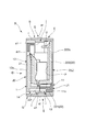
- FIG. 2 is a cross-sectional view taken along line XX in FIG.
- FIG. 8 is a cross-sectional view taken along the line YY.
- the perspective view in the same embodiment. The perspective view in the same embodiment.
- the perspective view in the same embodiment. The perspective view which shows the other embodiment.
- the perspective view in the same embodiment. The perspective view in the same embodiment.
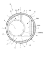
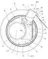
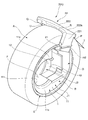
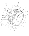
- FIGS. 1 to 15 show that the movable body 2 of the tape cutter B takes the accommodation posture (L). 7 to 12 and 14 show that the movable body 2 of the tape cutter B takes a cuttable posture (K).
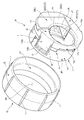
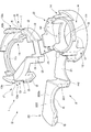
- FIG. 13 is a perspective view of a deployed state for explaining the structure of the cutter body D
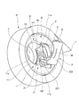
- FIG. 15 shows a movable body 2 of the tape cutter B between the accommodation posture (L) and the cuttable posture (K). An example of a certain state is shown.
- the tape cutter B of this embodiment includes a movable body 2 provided with a blade P capable of taking an accommodation posture (L) and a cuttable posture (K).
- the tape cutter B is configured so that the blade P capable of cutting the adhesive tape T can be accommodated in the hollow portion C of the wound adhesive tape body A formed by winding the adhesive tape T in the accommodating posture (L). ..
- the wound adhesive tape body A is one without a winding core, that is, a coreless one.
- the adhesive tape T constituting the wound adhesive tape body A is, for example, a masking tape.
- the wound adhesive tape body A is formed by winding and laminating an adhesive tape T having a predetermined length so as to surround the hollow portion C in a state where a hollow portion C in which the adhesive tape T does not exist is provided in the central portion. It was done.
- the coreless wound adhesive tape body A has a substantially annular shape when viewed from the side.
- the width dimension of the wound adhesive tape body A is set to be substantially the same as the width dimension of the outer ring member E in the tape cutter B (for example, 15 mm).
- the wound adhesive tape body A is subjected to a so-called glue killing treatment on the inner peripheral surface n facing the hollow portion C.
- the "glue-killing treatment” is a known treatment for preventing the adhesive force of an adhesive (not shown) applied to the adhesive tape T from being exerted.
- a tape for preventing the adhesive from being exposed It is processed by imprinting or printing that can form a non-adhesive portion.
- the tape cutter B is supported by a cutter body D having a blade P and a cutter body D so as to be rotatable relative to the cutter body D, and an outer ring member E in which an outer peripheral portion G can engage with an inner peripheral surface n of the wound adhesive tape body A. It is equipped with.
- the cutter body D is provided with a communication hole F into which a user's finger can be inserted when the movable body 2 is moved or when the cutter body D is rotated with respect to the outer ring member E.
- a concave groove portion I that engages with a positioning convex rail portion e1 provided on the inner peripheral portion of the outer ring member E is formed on the outer peripheral portion H of the base body 1.
- the concave groove portion I has a guide bottom surface i3 that can engage with the protruding tip surface of the convex rail portion e1, and a pair of guide side surfaces that can engage with both outer surfaces of the convex rail portion e1, that is, the first guide side surface i1 and the second guide. It has a side surface i2.
- a storage space sp capable of accommodating the movable body 2 is formed in the base body 1.
- the first base body component J1 has a left outer surface 11s which is an outer surface on one side, and can form a communication hole F penetrating in the left-right direction in cooperation with the second base body component J2.
- the left outer wall portion 11 having the left communication hole constituent portion 11r and the outer peripheral portion H that can form the outer peripheral portion H that engages with the outer ring member E in cooperation with the second base body constituent portion J2, that is, the left peripheral wall portion 13. I have.
- the left peripheral wall portion 13 has a first guide side surface i1 capable of partially guiding one side surface of the convex rail portion e1, a second guide side surface i2 capable of guiding the other side surface of the convex rail portion e1, and a second guide surface i2. It is provided with a guide bottom surface i3 located between the first guide side surface i1 and the second guide side surface i2.
- the first guide side surface i1 is formed on the retaining protrusion 13b of the elastic claw 13a, which is an elastic engaging body provided on the left peripheral wall portion 13.
- the elastic claw 13a can be temporarily elastically deformed by being pressed by the convex rail portion e1 projecting from the inner peripheral surface of the outer ring member E. ing.
- the elastic claw 13a provided on the cutter body D prevents the cutter body D attached to the outer ring member E from detaching from the outer ring member E.
- the second base body component J2 has a right outer surface 12s which is an outer surface on the other side, and can form a communication hole F penetrating in the left-right direction in cooperation with the first base body component J1.
- the right outer wall portion 12 having the right communication hole component portion 12r and the other, that is, the right peripheral wall portion 14 capable of forming the outer peripheral portion H engaged with the outer ring member E in cooperation with the first base body component portion J1. I have.
- the movable body 2 is connected to the right outer wall portion 12 via the first hinge portion m1 which is a hinge portion. That is, a connecting portion with the movable body 2 is provided on the inner surface of the right outer wall portion 12.
- the movable body 2 has a storage posture (L) housed in the storage space sp formed in the base body 1 as shown in FIGS. 1 to 6, and is wound as shown in FIGS. 7 to 12 and 14. It is possible to take a cuttable posture (K) in which the blade P is positioned on the outer surface side of the adhesive tape body A.
- the movable body 2 is a cutter member having an intermediate member 21 connected to the base body 1 via the first hinge portion m1 and a blade P connected to the intermediate member 21 via the second hinge portion m2. It is equipped with 22.
- the first hinge portion m1 and the second hinge portion m2 are so-called resin hinges formed of a thin synthetic resin that can be flexibly deformed.
- the movable body 2 makes it possible to operate the intermediate member 21 and the cutter member 22 between the cuttable posture (K) and the accommodating posture (L) by using the first hinge portion m1 and the second hinge portion m2.
- the intermediate member 21 has a substantially rectangular plate shape, and the first hinge portion m1 and the second hinge portion m2 forming linear shapes are provided at the base end portion and the tip end portion, respectively, so that the blade P is wound. It is movable so as to be substantially parallel to the outer surface of the adhesive tape body A. For example, as shown in FIGS.
- the tape cutter B winds the blade P around the outer circumference of the wound adhesive tape body A regardless of the amount of the remaining amount of the adhesive tape T in the wound adhesive tape body A. It can be positioned so as to be substantially parallel to the surface.
- the intermediate member 21 has a plate shape, the base end portion is connected to the second base body constituent portion J2 of the base body 1 via the first hinge portion m1, and the tip end portion is connected via the second hinge portion m2. It is connected to the cutter member 22.
- the main wall 222 has a plate shape.
- the entire main wall 222 is located in the accommodation space sp, and the outer surface 222s of the main wall 222 is substantially flush with the left outer wall portion 11 of the base body 1. It can be positioned to make an eggplant.
- the standing wall 221 takes a posture along one of the wound adhesive tape bodies A, that is, near the left outer portion, and hits the wound adhesive tape body A.
- the cutter member 22 can be positioned at a position suitable for cutting the adhesive tape T.
- the outer ring member E has an annular shape in a side view in a form that can be fitted inward to the wound adhesive tape body A.
- the outer ring member E is engaged with the outer peripheral portion H of the base body 1 and is supported so as to be rotatable relative to the base body 1.
- the width dimension of the outer ring member E is set to be substantially the same as the width dimension of the cutter body D when the movable body 2 takes the accommodation posture (L) (for example, 15 mm) or larger than the width dimension of the cutter body D.
- the tape cutter B is internally fitted into the hollow portion C of the wound adhesive tape body A having a size corresponding to the tape cutter B.
- the tip portion st of the rib r projecting from the outer ring member E is pressed against the inner peripheral surface n of the wound adhesive tape body A, and the outer ring member E and the wound adhesive tape body A are connected so that they can rotate integrally.
- the intermediate member 21 Since the intermediate member 21 is connected to the base body 1 via the first hinge portion m1, it gradually rises from the left outer wall portion 11 as the cutter member 22 moves outward. Further, the cutter member 22 connected to the intermediate member 21 via the second hinge portion m2 gradually moves away from the base body 1 by the user's pull-out operation, and is at a predetermined position where the adhesive tape T can be cut, that is, winding adhesive. It will move to the outer surface side of the tape body A.
- the upright wall 221 of the cutter member 22 is located on the left side of the wound adhesive tape body A and is wound.
- the main wall 222 of the cutter member 22 is located on the outer peripheral surface side of the adhesive tape body A.
- the posture-maintaining protrusion U projecting downward from the main wall 222 is located on the right side surface side of the wound adhesive tape body A, and is engaged with respect to the right side surface portion of the wound adhesive tape body A. It has become a match.
- the cutter member 22 is provided on the main wall 222 with the upright wall 221 and the posture-maintaining protrusion U cooperating with each other and positioned with respect to the wound adhesive tape body A.
- the blade P is configured to be able to take a suitable posture for easily cutting the adhesive tape T.
- the drawn adhesive tape T is pulled toward the blade P of the cutter member 22 in the cuttable posture (K), so that the adhesive tape T is cut by the blade P.
- the movable body 2 When the process for cutting the adhesive tape T is completed, the movable body 2 is moved from the cuttable posture (K) to the accommodation posture (L) through the reverse procedure of the above-mentioned procedure. Finally, by engaging the engaging convex portion Q formed at the rear end portion of the cutter member 22 with the engaging concave portion V provided in the base body 1, the movable body 2 preferably has the accommodation posture (L). Will be retained.
- the wound adhesive tape body A when not in use, has a compact posture that does not overlap the outer surface and the outer peripheral surface of the wound adhesive tape body A and does not impair the appearance of the wound adhesive tape body A. It is possible to provide a tape cutter B having a structure that is easy to use while holding it in the hand at the time of use.
- the cutter member 22 has an upright wall 221 whose base end is connected to the second hinge portion m2, and a main wall 222 provided with a blade P and extending from the tip of the upright wall 221 in a direction intersecting the upright wall 221. It is equipped with. Therefore, by having the upright wall 221 and the main wall 222, the cutter member 22 can be suitably positioned with respect to the wound adhesive tape body A in order to cut the adhesive tape T.
- the movable body 2 has a storage posture (L) housed in the storage space sp formed in the base body 1 and a cuttable posture (K) in which the blade P is positioned on the outer peripheral surface side of the wound adhesive tape body A. Can be taken.
- the cutter body D which has a compact posture in the accommodation posture (L) and a suitable posture in which the adhesive tape T can be cut on the outer peripheral surface side of the wound adhesive tape body A in the cuttable posture (K). It has become possible.
- the tape cutter B is arranged in the hollow portion C of the wound adhesive tape body A formed by winding the adhesive tape T, and has a blade P capable of cutting the adhesive tape T. It includes a cutter body D and an outer ring member E that is rotatably supported with respect to the cutter body D and whose outer peripheral portion G can engage with the inner peripheral surface n of the wound adhesive tape body A.
- the outer ring member E can rotate relative to the cutter body D in a state where the outer ring member E is appropriately positioned with respect to the cutter body D.
- the outer ring member E is set smaller than the width dimension of the cutter body D.
- the movable body may be provided with two or more hinge portions. Further, the movable body may be provided with a plurality of intermediate members having hinge portions arranged at both ends.
Abstract
不使用時にはコンパクトな姿勢をなすとともに使用時において手に持ったまま使用し易い構成を有したテープカッターを提供すべく、粘着テープTが巻回されてなる巻回粘着テープ体Aの中空部に、粘着テープTを切断し得る刃Pを収容可能に構成されたテープカッターBであり、中空部に配設されたベース体1と、刃Pが設けられベース体1に対して相対移動可能に構成され巻回粘着テープ体Aの外面近傍に刃Pを移動させ得る可動体2とを備えたものとした。
Description
本発明は、テープカッターに関する。
従来から、粘着テープが巻回されてなる巻回粘着テープ体に装着され不使用時はコンパクトな姿勢を採り得るように構成されたテープカッターが知られている(例えば、特許文献1を参照)。
しかしながら、従来のものは、使用する際に天板等の載置面に載せ置かなければならず、必ずしも使用者が手に取った状態で柔軟に使用し得るものとはなっていなかった。
しかも、従来のものは、使用する際のカッターの位置が巻回粘着テープ体の外面から過度に離れたものとなっていたため、巻回粘着テープ体から粘着テープを過剰に引き出さざるを得ないものとなっていた。
本発明は、以上のような事情に着目してなされたもので、少なくとも、不使用時にはコンパクトな姿勢をなすとともに使用時において手に持ったまま使用し易い構成を有したテープカッターを提供することにある。
すなわち、本発明は次の構成をなしている。
請求項1に係る発明は、粘着テープが巻回されてなる巻回粘着テープ体の中空部に、前記粘着テープを切断し得る刃を収容可能に構成されたテープカッターであって、前記中空部に収容された前記刃を前記巻回粘着テープ体の外面近傍に移動させ得る可動体を備えたテープカッターである。
請求項2に係る発明は、前記中空部に配設されたベース体を備えたものであり、前記可動体が、前記刃を有し前記ベース体に対して相対移動可能に構成されている請求項1記載のテープカッターである。
請求項3に係る発明は、前記可動体が、前記刃を前記巻回粘着テープ体の外面に対して略平行をなすように移動可能である請求項1又は2記載のテープカッターである。
請求項4に係る発明は、前記可動体が、前記ベース体に対して第一ヒンジ部を介して連結された中間部材と、この中間部材に対して第二ヒンジ部を介して連結された前記刃を有するカッター部材とを備えたものである請求項2記載のテープカッターである。
請求項5に係る発明は、前記カッター部材が、基端部が前記第二ヒンジ部と接続される起立壁と、前記刃が設けられ前記起立壁の先端から当該起立壁と交差する方向に延出した主壁とを備えたものである請求項4記載のテープカッターである。
請求項6に係る発明は、前記可動体が、前記ベース体に形成された収容空間に収容された収容姿勢と、前記巻回粘着テープ体の外面側に前記刃を位置させた切断可能姿勢とを採り得るものである請求項2、4又は5記載のテープカッターである。
請求項7に係る発明は、前記ベース体及び前記可動体によりカッター本体が構成されたものであり、前記カッター本体が、前記可動体を移動させる際に使用者の指が挿入される連通孔を備えている請求項2、4、5又は6記載のテープカッターである。
請求項8に係る発明は、前記ベース体の外周部と係わり合い当該ベース体に対して相対回転可能に支持された外輪部材を備えたものであり、前記外輪部材の外周部が前記巻回粘着テープ体の内周面に係合し得るものである請求項2、4、5、6又は7記載のテープカッターである。
以上説明したように本発明によれば、不使用時にはコンパクトな姿勢をなすとともに使用時において手に持ったまま使用し易い構成を有したテープカッターを提供することができる。
以下、本発明の一実施形態を、図1~15を参照して説明する。なお、図1~6は、テープカッターBの可動体2が収容姿勢(L)を採るものを示している。図7~12、及び、14は、テープカッターBの可動体2が切断可能姿勢(K)を採るものを示している。図13は、カッター本体Dの構造を説明するための展開状態の斜視図であり、図15は、テープカッターBの可動体2が収容姿勢(L)と切断可能姿勢(K)との間にある状態の一例を示している。
この実施形態のテープカッターBは、収容姿勢(L)と切断可能姿勢(K)とを採り得る刃Pを設けた可動体2を備えている。テープカッターBは、収容姿勢(L)において、粘着テープTが巻回されてなる巻回粘着テープ体Aの中空部Cに、粘着テープTを切断し得る刃Pが収容可能に構成されている。
巻回粘着テープ体Aは、巻芯が設けられていないもの、すなわち、コアレスのものとなっている。巻回粘着テープ体Aを構成する粘着テープTは、例えば、マスキングテープである。巻回粘着テープ体Aは、中央部に粘着テープTの存在しない中空部Cを設けた状態で、その中空部Cを囲むようにして所定の長さを有する粘着テープTを巻回積層することにより形成されたものである。コアレスの巻回粘着テープ体Aは、側面視において略円環形状をなしたものである。巻回粘着テープ体Aの幅寸法は、テープカッターBにおける外輪部材Eの幅寸法と略同じ(例えば、15mm)に設定されている。
巻回粘着テープ体Aは、中空部Cを臨む内周面nに対していわゆる糊殺し処理が施されている。なお、「糊殺し処理」とは、粘着テープTに塗布された図示しない粘着剤の粘着力を発揮させないようにするための既知の処理であり、例えば、粘着剤の露出を防止するためのテープを添着したり非接着部分を形成し得る印刷を施したりすることにより処理されている。
テープカッターBは、刃Pを有したカッター本体Dと、カッター本体Dに対して相対回転可能に支持され外周部Gが巻回粘着テープ体Aの内周面nに係合し得る外輪部材Eとを備えたものである。
カッター本体Dは、中空部Cに配設されたベース体1と、刃Pが設けられベース体1に対して相対移動可能すなわちベース体1に対して出没可能に構成され切断可能姿勢(K)において巻回粘着テープ体Aの外周面近傍に刃Pを移動させ得る可動体2とを備えたものである。カッター本体Dは、例えば、図5に示すように、収容姿勢(L)において、その全体が外輪部材Eの中空部esに収容され得るように構成されている。カッター本体Dは、収容姿勢(L)において、側面視において略円形をなしている。
カッター本体Dには、可動体2を移動させる際やカッター本体Dを外輪部材Eに対して回転させる際に、使用者の指が挿入され得る連通孔Fが設けられている。ベース体1の外周部Hには、外輪部材Eの内周部に設けられた位置決め用の凸レール部e1と係り合う凹溝部Iが形成されている。凹溝部Iは、凸レール部e1の突出先端面と係合し得る案内底面i3と、凸レール部e1の両外側面と係合し得る一対の案内側面すなわち第一案内側面i1及び第二案内側面i2を有するものである。ベース体1には、可動体2を収容し得る収容空間spが形成されている。
ベース体1は、その全体が外輪部材Eにより囲まれた空間すなわち中空部es内に常に配設されている。ベース体1は、図13に示すように、帯状又は板状の連結部材J3を介して相互に連結された第一のベース体構成部J1及び第二のベース体構成部J2を備えている。そして、連結部材J3に対して枢結された第一のベース体構成部J1の内面側と連結部材J3に対して枢結された第二のベース体構成部J2の内面側とを突き合わせることにより、例えば、図6に示されるような一体的な塊状をなしたベース体1が形成されている。
第一のベース体構成部J1は、一方側の外側面たる左外側面11sを有するとともに第二のベース体構成部J2と協働して左右方向に貫通した連通孔Fを形成し得る一方すなわち左の連通孔構成部11rを有した左外壁部分11と、第二のベース体構成部J2と協働して外輪部材Eと係り合う外周部Hを形成し得る一方すなわち左周壁部分13とを備えている。
左周壁部分13には、部分的に、凸レール部e1の一方の側面を案内し得る第一案内側面i1と、凸レール部e1の他方の側面を案内し得る第二案内側面i2と、第一案内側面i1と第二案内側面i2との間に位置する案内底面i3とを備えている。
第一案内側面i1は、図6に示すように、左周壁部分13に設けられた弾性係合体たる弾性爪13aの抜け止め突部13bに形成されている。弾性爪13aは、カッター本体Dが、外輪部材Eに装着される際に当該外輪部材Eの内周面に突設された凸レール部e1に押圧されて一時的に弾性変形し得るものとなっている。換言すれば、カッター本体Dに設けられた弾性爪13aにより、外輪部材Eに装着されたカッター本体Dが当該外輪部材Eから離脱しないようになっている。
第二のベース体構成部J2は、他方側の外側面たる右外側面12sを有するとともに第一のベース体構成部J1と協働して左右方向に貫通した連通孔Fを形成し得る他方すなわち右の連通孔構成部12rを有した右外壁部分12と、第一のベース体構成部J1と協働して外輪部材Eと係り合う外周部Hを形成し得る他方すなわち右周壁部分14とを備えている。
右外壁部分12には、ヒンジ部たる第一ヒンジ部m1を介して可動体2が接続している。すなわち、右外壁部分12の内面には、可動体2との接続部が設けられている。
右周壁部分14には、部分的に、凸レール部e1の他方の側面を案内し得る第二案内側面i2と、第一案内側面i1と第二案内側面i2との間に位置する案内底面i3とを備えている。
可動体2は、図1~6に示すように、ベース体1に形成された収容空間spに収容された収容姿勢(L)と、図7~12、及び、14に示すように、巻回粘着テープ体Aの外面側に刃Pを位置させた切断可能姿勢(K)とを採り得るものである。可動体2は、ベース体1に対して第一ヒンジ部m1を介して連結された中間部材21と、中間部材21に対して第二ヒンジ部m2を介して連結された刃Pを有するカッター部材22とを備えたものである。
第一ヒンジ部m1及び第二ヒンジ部m2は、可撓変形し得る薄肉の合成樹脂により形成されたいわゆる樹脂ヒンジと称されるものである。可動体2は、第一ヒンジ部m1及び第二ヒンジ部m2を利用して中間部材21及びカッター部材22を切断可能姿勢(K)と収容姿勢(L)との間で動作可能にしている。 この実施形態では、中間部材21を略矩形板状のものとし、基端部及び先端部にそれぞれ直線状をなす第一ヒンジ部m1及び第二ヒンジ部m2を設けているため、刃Pを巻回粘着テープ体Aの外面に対して略平行をなすように移動可能なものとなっている。例えば、図14<a><b>に示すように、テープカッターBは、巻回粘着テープ体Aにおける粘着テープTの残量の多寡に係わらず、刃Pを巻回粘着テープ体Aの外周面に対して略平行をなすように位置させることができるようになっている。
中間部材21は、板状をなし基端部が第一ヒンジ部m1を介してベース体1の第二のベース体構成部J2に接続したものであり、先端部が第二ヒンジ部m2を介してカッター部材22に接続したものである。
可動体2が収容姿勢(L)をなす時は、中間部材21が右外壁部分12の内面に沿う姿勢を採りつつ全体が収容空間sp内に位置している。一方で、可動体2が切断可能姿勢(K)をなす時は、中間部材21の先端部が収容空間spよりも外側に位置するとともに中間部材21が右外壁部分12の内面に対して起立する姿勢を採るようになっている。
カッター部材22は、基端部が第二ヒンジ部m2と接続する起立壁221と、刃Pが設けられ起立壁221の先端から当該起立壁221と交差する方向すなわち略直交する方向に延出した主壁222とを備えている。
起立壁221は、板状をなしている。可動体2が収容姿勢(L)をなす時は、起立壁221が右外壁部分12の内面に対して起立した姿勢を採りつつ全体が収容空間sp内に位置し、可動体2が切断可能姿勢(K)をなす時は起立壁221が巻回粘着テープ体Aの一方すなわち左の外側部近傍に沿う姿勢を採り当該巻回粘着テープ体Aと当接し得ることによりカッター部材22を位置決めし得るものとなっている。
主壁222は、板状をなしたものである。可動体2が収容姿勢(L)をなす時は、主壁222はその全体が収容空間sp内に位置するとともに当該主壁222の外面222sがベース体1の左外壁部分11と略面一をなすよう位置し得るものとなっている。
一方で、可動体2が切断可能姿勢(K)をなす時は、起立壁221が巻回粘着テープ体Aの一方すなわち左の外側部近傍に沿う姿勢を採り当該巻回粘着テープ体Aと当接し得ることによりカッター部材22を粘着テープTを切断するのに適した位置に位置決めし得るものとなっている。
主壁222は、前端部に設けられた刃Pと、後端部に設けられ連通孔Fの一部を形成し得るように湾曲状をなす切欠部Rと、後端部において後方に突設され収容姿勢(L)をなす時にベース体1に設けた係合凹部Vに係合し得る係合凸部Qと、切断可能姿勢(K)をなす時に巻回粘着テープ体Aの他方すなわち右の外側部近傍に位置するように突設された姿勢保持用の突起Uを備えている。
外輪部材Eは、巻回粘着テープ体Aに対して内嵌し得る形態をなした側面視において円環状をなすものである。外輪部材Eは、ベース体1の外周部Hと係わり合い当該ベース体1に対して相対回転可能に支持されている。
外輪部材Eの幅寸法は、可動体2が収容姿勢(L)を採る際のカッター本体Dの幅寸法と略同じ(例えば、15mm)又はカッター本体Dの幅寸法よりも大きく設定されている。
外輪部材Eは、その外周部Gが巻回粘着テープ体Aの内周面nに係合し得るものである。外輪部材Eの外周部Gには、巻回粘着テープ体Aの中空部Cへの挿入を促す挿入促進手段Sが設けられている。この実施形態における挿入促進手段Sは、外輪部材Eの外周部Gに形成され先端部stが中空部Cを臨む内周面nに係り合うリブrを設けたものである。
外輪部材Eの内周部における左右方向中央部には、カッター本体Dの外周部Hに設けられた凹溝部Iと係り合う位置決め用の凸レール部e1が周方向に連続して設けられている。
以下、本実施形態のテープカッターBの作動について概略的に説明する。
まず、テープカッターBを、当該テープカッターBに対応するサイズをなす巻回粘着テープ体Aの中空部Cに内嵌させる。テープカッターBを巻回粘着テープ体Aの中空部Cに挿入すると、外輪部材Eに突設されたリブrの先端部stが巻回粘着テープ体Aの内周面nに圧接し、外輪部材Eと巻回粘着テープ体Aとが一体的に回転し得るように連結されることになる。
次いで、カッター本体Dの連通孔Fに手指を挿入し、収容姿勢(L)の可動体2におけるカッター部材22の切欠部Rに触れて、カッター部材22をベース体1の収容空間spから外方すなわち切断可能姿勢(K)側に引き出す操作を行う。
可動体2を外側に引き出す操作を行うと、まず、カッター部材22の主壁222に突設された係合凸部Qとベース体1に設けられた係合凹部Vとの係わり合いが解かれ、可動体2がベース体1に対して移動可能な状態になる。
そして、中間部材21は、第一ヒンジ部m1を介してベース体1に接続しているので、カッター部材22の外方への移動に伴って左外壁部分11から徐々に立ち上がることになる。また、第二ヒンジ部m2を介して中間部材21に接続したカッター部材22は、使用者の引き出し操作によりベース体1から徐々に離れて行き、粘着テープTを切断し得る所定位置すなわち巻回粘着テープ体Aの外面側に移動することになる。
可動体2が収容姿勢(L)から動作して切断可能姿勢(K)にまで遷移すると、巻回粘着テープ体Aの左側面側には、カッター部材22の起立壁221が位置するとともに巻回粘着テープ体Aの外周面側にはカッター部材22の主壁222が位置することになる。また、主壁222から下方に突設された姿勢保持用の突起Uは、巻回粘着テープ体Aの右側面側に位置することになり、巻回粘着テープ体Aの右側面部に対して係合し得るものとなっている。
換言すれば、切断可能姿勢(K)において、カッター部材22は、起立壁221及び姿勢保持用の突起Uが協働して巻回粘着テープ体Aに対して位置決めされ、主壁222に設けた刃Pが粘着テープTを切断し易い好適な姿勢を採り得るように構成されている。
その後、カッター本体Dに対して、外輪部材Eに保持された巻回粘着テープ体Aを回転させつつ粘着テープAの先端部を探し出し、当該巻回粘着テープ体Aから使用者が希望する所定寸法の粘着テープTを引き出す。
しかる後に、引き出された粘着テープTを切断可能姿勢(K)にあるカッター部材22の刃Pに引き寄せることにより、当該粘着テープTを刃Pによって切断させる。
粘着テープTを切断するための過程を終えると、前述した手順と逆の手順を経て、可動体2を切断可能姿勢(K)から収容姿勢(L)に移行させる。最終的に、カッター部材22の後端部に形成された係合凸部Qを、ベース体1に設けた係合凹部Vに係り合わせることにより、可動体2は収容姿勢(L)を好適に保持されることになる。
以上説明したように、本実施形態に係るテープカッターBは、粘着テープTが巻回されてなる巻回粘着テープ体Aの中空部Cに、粘着テープTを切断し得る刃Pを収容可能に構成されたものである。そして、テープカッターBは、中空部Cに配設されたベース体1と、刃Pが設けられベース体1に対して相対移動可能に構成され巻回粘着テープ体Aの外面近傍に刃Pを移動させ得る可動体2とを備えたものである。
このため、本実施形態のものであれば、不使用時には巻回粘着テープ体Aの外側面及び外周面に重複することがなく当該巻回粘着テープ体Aの外観を損ねることのないコンパクトな姿勢をなすとともに使用時において手に持ったまま使用し易い構成を有したテープカッターBを提供することができるものとなる。
可動体2が、刃Pを巻回粘着テープ体Aの外周面に対して略平行をなすように移動可能である。このため、刃Pは巻回粘着テープ体Aにおける粘着テープTの残量の多寡に係わらず、粘着テープTを切断し得る適切な姿勢を採り得るものとなっている。
可動体2が、ベース体1に対して第一ヒンジ部m1を介して連結された中間部材21と、中間部材21に対して第二ヒンジ部m2を介して連結された刃Pを有するカッター部材22とを備えたものである。
このため、第一、第二のヒンジ部を設けた構成により、中間部材21及びカッター部材22を安定的な姿勢で動作させることができるものとなっている。
カッター部材22が、基端部が第二ヒンジ部m2と接続される起立壁221と、刃Pが設けられ起立壁221の先端から当該起立壁221と交差する方向に延出した主壁222とを備えたものである。このため、カッター部材22は、起立壁221と主壁222とを有することによって、粘着テープTを切断するために、巻回粘着テープ体Aに対して好適に位置決めされ得るものとなっている。
可動体2が、ベース体1に形成された収容空間spに収容された収容姿勢(L)と、巻回粘着テープ体Aの外周面側に刃Pを位置させた切断可能姿勢(K)とを採り得るものである。
このため、収容姿勢(L)ではコンパクトな姿勢をなすとともに切断可能姿勢(K)では粘着テープTを巻回粘着テープ体Aの外周面側において切断し得る好適な姿勢をなすカッター本体Dを提供し得るものとなっている。
ベース体1及び可動体2によりカッター本体Dが構成されたものであり、カッター本体Dが、可動体2を移動させる際に使用者の指が挿入される連通孔Fを備えている。このため、カッター本体Dは、コンパクトな姿勢をなしているにもかかわらず、連通孔Fに指を挿入することにより、可動体2を外部に容易に引き出し得るものとなっている。また、連通孔Fを利用して、カッター本体Dを外輪部材Eに対して回転させることも容易に行えるものとなる。
ベース体1の外周部Hと係わり合い当該ベース体1に対して相対回転可能に支持された外輪部材Eを備えたものである。そして、外輪部材Eの外周部Gが巻回粘着テープ体Aの内周面nに係合し得るものである。このため、カッター本体Dに対して、巻回粘着テープ体Aを回転させることができ、可動体2の刃Pによって粘着テープTを所望の位置で好適に切断得るものとなっている。
また、本実施形態に係るテープカッターBは、粘着テープTが巻回されてなる巻回粘着テープ体Aの中空部Cに配設されるものであり、粘着テープTを切断し得る刃Pを有したカッター本体Dと、このカッター本体Dに対して相対回転可能に支持され外周部Gが巻回粘着テープ体Aの内周面nに係合し得る外輪部材Eとを備えている。
このため、粘着テープTを切断し得る刃Pを有したカッター本体Dに対して巻回粘着テープ体Aが円滑に回転し得る構成を有したテープカッターBを提供することができるものとなる。
外輪部材Eの内周部に設けられた位置決め用の凸レール部e1と、カッター本体Dの外周部Hに設けられ凸レール部e1と係り合う凹溝部Iとを備えているものである。
このため、カッター本体Dに対して外輪部材Eが適切に位置決めされた状態で、外輪部材Eがカッター本体Dに対して相対回転し得るものとなっている。
凹溝部Iが、凸レール部e1の一方の側面を案内し得る案内面たる第一案内側面i1を備えたものであり、カッター本体Dが、外輪部材Eに装着される際に凸レール部e1に押圧されて一時的に弾性変形し得る弾性爪13aを有し、当該弾性爪13aに第一案内側面i1が設けられている。
このため、外輪部材Eがカッター本体Dに対して好適に装着できるだけでなく、装着後は、カッター本体Dから離脱し難いものとなっている。
外輪部材Eの外周部Gに、巻回粘着テープ体Aの中空部Cへの挿入を促す挿入促進手段Sが設けられており、当該挿入促進手段Sが、外輪部材Eの外周部Gに形成され先端部stが巻回粘着テープ体Aの中空部Cを臨む内周面nに係り合うリブrを設けたものである。
このため、外輪部材Eを巻回粘着テープ体Aの中空部Cに対して円滑に挿入し得るとともに、挿入後の外輪部材Eが巻回粘着テープ体Aの内周面nに対して好適に係り合って、外輪部材Eと巻回粘着テープ体Aが適切に一体的に回動し得るものとなっている。
カッター本体Dに、使用者の指が挿入される連通孔Fが設けられている。このため、使用者は、カッター本体Dを、外輪部材E及び巻回粘着テープ体Aに対して回転させやすいものとなっている。
テープカッターBは、刃Pが収容姿勢(L)にある場合は、巻回粘着テープ体Aの外側部の全域及び外周部の全域を外部に露出させることができるようになっている。このため、テープカッターBに装着される巻回粘着テープ体Aの外観的特徴を使用者に対して視認させやすいものとなっている。
例えば、巻回粘着テープ体Aの粘着テープ体Tが、外面に種々の絵柄等の印刷表示が設けられやすいマスキングテープであれば、本実施形態のテープカッターBを適用することが好適である。すなわち、テープカッターBは、マスキングテープの印刷表示を外部から視認可能な状態に維持しやすいため、マスキングテープの印刷表示に基づく好適な外観を提供しつつ、必要時において当該マスキングテープを切断し得る操作を実施することができるものとなる。
なお、本発明は、以上に詳述した実施形態に限られるものではない。
他の実施形態であるテープカッターBについて、図16~19を参照して説明する。
この実施形態のテープカッターBは、上述した実施形態と比較して、主として、可動体2におけるカッター部材22の構成、及び、外輪部材Eのカッター本体Dに対する幅が相違したものとなっている。
カッター部材22における主壁222の外面222sには、湾曲状の切欠部Rに沿うように、使用者の手指を掛けやすくするための突起Wが設けられている。また、カッター部材22は、起立壁221の反対側に位置する主壁222の端縁から当該主壁222に対して略直交する方向に突設された姿勢保持用の延出壁Uを備えており、その外面には、収容姿勢(L)においてベース体1と係合し得る係合凸部Qが設けられている。すなわち、延出壁Uに突設された係合凸部Qは、収容姿勢(L)をなす時にベース体1に設けた係合凹部Vに係合し得るものとなっている。
外輪部材Eは、カッター本体Dの幅寸法よりも小さく設定されている。
以上に述べた他の実施形態であっても、所期の目的を達成し得るものとなっている。
巻回粘着テープ体は、マスキングテープに限られるものではない。
また、巻回粘着テープ体は、コアレスのものでなくてもよく、巻芯を有したものであってもよい。
テープカッターは、外輪部材を備えていないものであってもよい。つまり、テープカッターが、巻回粘着テープ体に内嵌し得るカッター本体のみにより構成されたものであってもよい。
外輪部材の内周部に凹溝部が設けられたものであり、当該凹溝部に係り合う凸部又は凸レール部がカッター本体に設けられたものであってもよい。
テープカッターを構成するカッター本体や外輪部材の大きさは、装着すべき巻回粘着テープ体の大きさに応じて適宜設定され得るものであることはいうまでもない。
可動体は、二以上の複数のヒンジ部を設けたものであってもよい。また、可動体には、両端部にヒンジ部を配した中間部材を複数設けるようにしてもよい。
可動体は、刃を設けたカッター部材とベース体との間を繋ぐ可撓性を有した紐状、帯状、又は、ワイヤー状の中間部材を設けたものとしてもよい。
刃を有する可動体は、ベース体の左側において収容姿勢と切断可能姿勢との間で移動し得るものには限られず、ベース体の右側において収容姿勢と切断可能姿勢との間で移動し得るものであってもよい。
外輪部材は、必ずしも側面視において円環状をなすものに限られるものではなく、円環状とは異なる異形状のものであってもよい。
外輪部材の幅寸法は、カッター本体の幅寸法と略同じ寸法に設定されたものであってもよいし、カッター本体の幅寸法よりも小さく設定されたものであってもよい。
その他、各部の具体的構成についても上記実施形態に限られるものではなく、本発明の趣旨を逸脱しない範囲で種々変形が可能である。
A…巻回粘着テープ体
B…テープカッター
D…カッター本体
E…外輪部材
T…粘着テープ
1…ベース体
2…可動体
P…刃
B…テープカッター
D…カッター本体
E…外輪部材
T…粘着テープ
1…ベース体
2…可動体
P…刃
Claims (8)
- 粘着テープが巻回されてなる巻回粘着テープ体の中空部に、前記粘着テープを切断し得る刃を収容可能に構成されたテープカッターであって、
前記中空部に収容された前記刃を前記巻回粘着テープ体の外面近傍に移動させ得る可動体を備えたテープカッター。 - 前記中空部に配設されたベース体を備えたものであり、
前記可動体が、前記刃を有し前記ベース体に対して相対移動可能に構成されている請求項1記載のテープカッター。 - 前記可動体が、前記刃を前記巻回粘着テープ体の外面に対して略平行をなすように移動可能である請求項1又は2記載のテープカッター。
- 前記可動体が、前記ベース体に対して第一ヒンジ部を介して連結された中間部材と、この中間部材に対して第二ヒンジ部を介して連結された前記刃を有するカッター部材とを備えたものである請求項2記載のテープカッター。
- 前記カッター部材が、基端部が前記第二ヒンジ部と接続される起立壁と、前記刃が設けられ前記起立壁の先端から当該起立壁と交差する方向に延出した主壁とを備えたものである請求項4記載のテープカッター。
- 前記可動体が、前記ベース体に形成された収容空間に収容された収容姿勢と、前記巻回粘着テープ体の外面側に前記刃を位置させた切断可能姿勢とを採り得るものである請求項2、4又は5記載のテープカッター。
- 前記ベース体及び前記可動体によりカッター本体が構成されたものであり、
前記カッター本体が、前記可動体を移動させる際に使用者の指が挿入される連通孔を備えている請求項2、4、5又は6記載のテープカッター。 - 前記ベース体の外周部と係わり合い当該ベース体に対して相対回転可能に支持された外輪部材を備えたものであり、
前記外輪部材の外周部が前記巻回粘着テープ体の内周面に係合し得るものである請求項2、4、5、6又は7記載のテープカッター。
Priority Applications (3)
| Application Number | Priority Date | Filing Date | Title |
|---|---|---|---|
| PCT/JP2020/006128 WO2021166049A1 (ja) | 2020-02-17 | 2020-02-17 | テープカッター |
| JP2022501419A JP7287565B2 (ja) | 2020-02-17 | 2020-02-17 | テープカッター |
| CN202080096347.4A CN115087525B (zh) | 2020-02-17 | 2020-02-17 | 带切割器 |
Applications Claiming Priority (1)
| Application Number | Priority Date | Filing Date | Title |
|---|---|---|---|
| PCT/JP2020/006128 WO2021166049A1 (ja) | 2020-02-17 | 2020-02-17 | テープカッター |
Publications (1)
| Publication Number | Publication Date |
|---|---|
| WO2021166049A1 true WO2021166049A1 (ja) | 2021-08-26 |
Family
ID=77390678
Family Applications (1)
| Application Number | Title | Priority Date | Filing Date |
|---|---|---|---|
| PCT/JP2020/006128 WO2021166049A1 (ja) | 2020-02-17 | 2020-02-17 | テープカッター |
Country Status (3)
| Country | Link |
|---|---|
| JP (1) | JP7287565B2 (ja) |
| CN (1) | CN115087525B (ja) |
| WO (1) | WO2021166049A1 (ja) |
Citations (2)
| Publication number | Priority date | Publication date | Assignee | Title |
|---|---|---|---|---|
| JPS3923600Y1 (ja) * | 1958-08-27 | 1964-08-14 | ||
| JPH0553887U (ja) * | 1991-12-27 | 1993-07-20 | 宗晴 南條 | 巻きテープ切断具 |
Family Cites Families (4)
| Publication number | Priority date | Publication date | Assignee | Title |
|---|---|---|---|---|
| KR100533838B1 (ko) * | 2004-04-30 | 2005-12-07 | 이상철 | 접착테이프용 디스펜서 |
| CN201343329Y (zh) * | 2008-06-20 | 2009-11-11 | 刘玉菁 | 胶带切割器 |
| JP3189212U (ja) * | 2013-12-18 | 2014-02-27 | エスコ株式会社 | テープカッターおよび切断カートリッジ |
| JP2017114587A (ja) * | 2015-12-21 | 2017-06-29 | スリーエム イノベイティブ プロパティズ カンパニー | テープホルダ |
-
2020
- 2020-02-17 JP JP2022501419A patent/JP7287565B2/ja active Active
- 2020-02-17 WO PCT/JP2020/006128 patent/WO2021166049A1/ja active Application Filing
- 2020-02-17 CN CN202080096347.4A patent/CN115087525B/zh active Active
Patent Citations (2)
| Publication number | Priority date | Publication date | Assignee | Title |
|---|---|---|---|---|
| JPS3923600Y1 (ja) * | 1958-08-27 | 1964-08-14 | ||
| JPH0553887U (ja) * | 1991-12-27 | 1993-07-20 | 宗晴 南條 | 巻きテープ切断具 |
Also Published As
| Publication number | Publication date |
|---|---|
| JPWO2021166049A1 (ja) | 2021-08-26 |
| CN115087525B (zh) | 2023-11-24 |
| CN115087525A (zh) | 2022-09-20 |
| JP7287565B2 (ja) | 2023-06-06 |
Similar Documents
| Publication | Publication Date | Title |
|---|---|---|
| EP1339547B1 (en) | Hand-held adhesive tape dispenser | |
| JP2005193410A (ja) | 転写具 | |
| JP2007532446A (ja) | 両面粘着テープディスペンサ | |
| US6896025B2 (en) | Adhesive tape adhering device | |
| WO2021166049A1 (ja) | テープカッター | |
| JP4228915B2 (ja) | スライド部材のロック構造及び転写具 | |
| WO2021166051A1 (ja) | テープカッター | |
| JP7341802B2 (ja) | テープカッター | |
| US20100101733A1 (en) | Desktop double-sided adhesive tape dispenser | |
| JP2005193999A (ja) | 転写具 | |
| JP4513290B2 (ja) | 転写具 | |
| JP2018002471A (ja) | テープカッター | |
| JP2021116151A (ja) | テープカッター | |
| JP2005179047A (ja) | テープカッター | |
| CN108778772B (zh) | 打印型涂膜转印工具 | |
| JP2009143689A (ja) | テープ切断機及びテープ切断補助機 | |
| JP2012157986A (ja) | 印字ラベル作成装置 | |
| JP6190114B2 (ja) | ラベルの作成具 | |
| JP7220826B1 (ja) | 剥離用爪付きテープカッター | |
| CA2622962A1 (en) | Button cell dispenser | |
| KR200325399Y1 (ko) | 롤러 테이프디스펜서 | |
| JP4367221B2 (ja) | 転写具 | |
| JP4895769B2 (ja) | テープホルダ | |
| JP3047722U (ja) | ラップフィルムの収納ケース | |
| JP2006192625A (ja) | 紐付き筆記具 |
Legal Events
| Date | Code | Title | Description |
|---|---|---|---|
| 121 | Ep: the epo has been informed by wipo that ep was designated in this application |
Ref document number: 20920300 Country of ref document: EP Kind code of ref document: A1 |
|
| ENP | Entry into the national phase |
Ref document number: 2022501419 Country of ref document: JP Kind code of ref document: A |
|
| NENP | Non-entry into the national phase |
Ref country code: DE |
|
| 122 | Ep: pct application non-entry in european phase |
Ref document number: 20920300 Country of ref document: EP Kind code of ref document: A1 |