WO2021124986A1 - Robot et robot à double bras - Google Patents
Robot et robot à double bras Download PDFInfo
- Publication number
- WO2021124986A1 WO2021124986A1 PCT/JP2020/045671 JP2020045671W WO2021124986A1 WO 2021124986 A1 WO2021124986 A1 WO 2021124986A1 JP 2020045671 W JP2020045671 W JP 2020045671W WO 2021124986 A1 WO2021124986 A1 WO 2021124986A1
- Authority
- WO
- WIPO (PCT)
- Prior art keywords
- arm
- axis
- robot
- elevating
- end side
- Prior art date
Links
Images


Classifications
-
- B—PERFORMING OPERATIONS; TRANSPORTING
- B25—HAND TOOLS; PORTABLE POWER-DRIVEN TOOLS; MANIPULATORS
- B25J—MANIPULATORS; CHAMBERS PROVIDED WITH MANIPULATION DEVICES
- B25J9/00—Programme-controlled manipulators
- B25J9/06—Programme-controlled manipulators characterised by multi-articulated arms
Definitions
- the disclosed embodiment relates to a robot and a dual-arm robot.
- SCARA robot horizontal articulated robot
- each arm of a dual-arm SCARA robot is provided with a slide mechanism that moves up and down vertically to improve accessibility to an object (see, for example, Patent Document 1).
- the above-mentioned conventional technology has a problem that interference between robot arms and obstacles is likely to occur, that is, an interference area is likely to be widened.
- an interference area is likely to be widened.
- the interference area is wide, the actual operation area in which the work can be performed without interference is narrowed in the original movable area of the robot, and as a result, the work efficiency by the robot is lowered.
- such a problem is not limited to a double-armed robot, but is a problem that also occurs in a so-called single-armed robot. Further, such a problem occurs in both a robot that expands and contracts in the horizontal direction and a robot that expands and contracts in the vertical direction.
- One aspect of the embodiment is to provide a robot and a dual-arm robot capable of reducing an interference region.
- the robot includes a first horizontal arm, a second horizontal arm, and an elevating arm.
- the first horizontal arm turns around the first axis.
- the base end side of the second horizontal arm is supported by the tip end side of the first horizontal arm, and the second horizontal arm swivels around a second axis parallel to the first axis.
- the base end side of the elevating arm is supported on the tip end side of the second horizontal arm, and the end effector that can be attached to the tip end side is lifted and lowered.
- the second horizontal arm is curved in either turning direction.
- the elevating arm is arranged inside the curve in the second horizontal arm in a plan view.
- the robot includes a first arm, a second arm, and a third arm.
- the first arm swivels around the first swivel axis.
- the base end side of the second arm is supported by the tip end side of the first arm, and the second arm swivels around a second swivel shaft parallel to the first swivel shaft.
- the third arm is supported on the tip end side of the second arm and swivels around a third swivel shaft parallel to the second swivel shaft.
- the first arm, the second arm, and the third arm are arranged in the order of the first arm, the second arm, and the third arm when viewed from the direction of the first turning axis.
- the second distance which is the inter-axis distance between the second swivel shaft and the third swivel shaft
- the first distance which is the inter-axis distance between the first swivel shaft and the second swivel shaft.
- FIG. 1 is a top view of the robot according to the embodiment.
- FIG. 2 is a top view showing the curved shape of the second horizontal arm.
- FIG. 3A is a front view of the dual-arm robot.
- FIG. 3B is a perspective view of the dual-arm robot.
- FIG. 4A is a top view of the dual-arm robot.
- FIG. 4B is a top view showing a posture in which the elevating arms are opposed to each other.
- FIG. 5 is an explanatory diagram showing the relationship between the arm length of the elevating arm and the distance between the axes.
- FIG. 6A is a side view showing the basic posture of the elevating arm.
- FIG. 6B is a side view showing the cooperative operation posture of the elevating arm.
- FIG. 7 is an explanatory diagram showing the moving speed for each combination of the inter-axis distance ratio and the angular velocity ratio.
- FIG. 8A is a schematic view No. 1 showing an example of actuator arrangement.
- FIG. 8B is a schematic view 2 showing an example of actuator arrangement.
- FIG. 9 is a schematic diagram showing an arrangement example of a plurality of robots.
- FIG. 10 is a block diagram showing a configuration of a robot system.
- the robot is equipped with an end effector which is a tool for gripping the work with a claw
- the end effector may be a suction type tool, and a sealing material is applied, painted, and welded. It may be a tool that performs such as.
- FIG. 1 is a top view of the robot 100 according to the embodiment.
- FIG. 1 shows a three-dimensional Cartesian coordinate system in which the XY plane corresponds to the horizontal plane, including the Z axis whose vertical upward direction is the positive direction, for the sake of clarity.
- Cartesian coordinate system may also be shown in other drawings used in the following description.
- the robot 100 includes a first horizontal arm 11 and a second horizontal arm 12, which are horizontal arms 10, and an elevating arm 20.
- An end effector 200 can be attached to the tip end side of the elevating arm 20.
- the elevating arm 20 includes a plurality of arms and each arm swivels around a horizontal axis to expand and contract to elevate and retract the end effector 200 will be described.
- the present invention is not limited to this, and the elevating arm 20 may be a slide mechanism for vertically elevating or lowering, or an arm group including such a slide mechanism.
- the base end side of the first horizontal arm 11 is attached to, for example, the base portion B.
- the circular base portion B is shown in FIG. 1 in a plan view, the three-dimensional shape of the base portion B is not limited to a columnar shape, and may be any shape such as a rectangular parallelepiped shape or an elliptical columnar shape. Further, the base portion B may be a support member such as a floor.
- the first horizontal arm 11 is supported on the base end side by a support member such as a base portion B, and swivels around a vertically oriented first axis A1.
- the base end side of the second horizontal arm 12 is supported by the tip end side of the first horizontal arm 11, and the second horizontal arm 12 swivels around the second axis A2 parallel to the first axis A1.
- the elevating arm 20 is supported on the base end side on the tip end side of the second horizontal arm 12, and raises and lowers the end effector 200 that can be attached to the tip end side.
- the second horizontal arm 12 is curved in any turning direction around the first axis A1 which is the vertical axis, and the elevating arm 20 is curved inside Si in the second horizontal arm 12 in a plan view. Be placed.
- the opposite side of the curved inner Si is referred to as the curved outer So.
- FIG. 1 shows a case where the second horizontal arm 12 has a shape curved clockwise of the second axis A2, it may have a shape curved counterclockwise.
- the elevating arm 20 on the curved inner Si of the second horizontal arm 12, which is a curved arm, the region of the curved inner Si that does not easily interfere with obstacles or the like can be effectively utilized, and the robot can be effectively utilized. It is possible to reduce the interference region where 100 interferes with obstacles and the like.
- the elevating arm 20 includes a first elevating arm 21, a second elevating arm 22, and a third elevating arm 23.
- the base end side of the first elevating arm 21 is supported by the tip end side of the second horizontal arm 12, and the first elevating arm 21 swivels around a third axis A3 perpendicular to the first axis A1.
- the base end side of the second elevating arm 22 is supported by the tip end side of the first elevating arm 21, and the second elevating arm 22 swivels around the fourth axis A4 parallel to the third axis A3.
- the third elevating arm 23 is supported on the tip end side of the second elevating arm 22 and swivels around the fifth axis A5 parallel to the fourth axis A4.
- the third elevating arm 23 has a rotating portion 23r that rotates the end effector 200 around the sixth axis A6 perpendicular to the fifth axis A5.
- the rotating portion 23r may be provided on the bottom surface side of the third elevating arm 23, or may be provided on the side surface side excluding the second elevating arm 22 side.
- the robot 100 is an articulated robot having 6 axes of 1st axis A1 to 6th axis A6.
- the end effector 200 keeps the direction of the sixth axis A6, which is the "tip axis". Can be moved to any three-dimensional position.
- the elevating arm 20 by forming the elevating arm 20 into a three-arm configuration, it is possible to sufficiently secure the elevating range of the elevating operation.
- the detailed relationship between the length of each arm and the distance between the axes of the elevating arm 20 will be described later with reference to FIG.
- FIG. 2 is a top view showing the curved shape of the second horizontal arm 12. Note that FIG. 2 corresponds to the second horizontal arm 12 and the elevating arm 20 of the robot 100 shown in FIG.
- the second horizontal arm 12 has a shape in which the base end side and the tip end side of the curved outer So are linear, respectively, and the base end side and the tip end side are smoothly connected by a curve in a plan view.
- the base end side and the tip end side of the curved inner Si are also linear, respectively, and have a shape in which the base end side and the tip end side are smoothly connected by a curve, similarly to the curved outer side So.
- the elevating arm 20 is arranged in a straight line portion on the tip side of the curved inner Si.
- FIG. 2 shows a case where the tip side of the curved outer So and the tip side of the curved inner Si are parallel, it is not always necessary that they are parallel.
- first virtual tangent line TL1 the virtual tangent line in contact with the tip end side of the curved outer So in the second horizontal arm 12
- second virtual tangent TL2 The farthest virtual tangent is referred to as “second virtual tangent TL2”.
- area W the area sandwiched between the first virtual tangent line TL1 and the second virtual tangent line TL2
- the entire elevating arm 20 fits in the region W sandwiched between the first virtual tangent line TL1 and the second virtual tangent line TL2. That is, the second horizontal arm 12 is curved so that the entire elevating arm 20 fits in the region W.
- the second horizontal arm 12 is curved so that the entire elevating arm 20 fits in the region W.
- FIG. 2 a case where a part of the end effector 200 protrudes from the area W is shown, but the outer shape of the end effector 200 may be shaped so as to fit in the area W. By doing so, the interference region due to the end effector 200 can be further reduced.
- the robot 100 also reduces the interference region by accommodating a cable such as a cable connected to the end effector 200 inside the housing, and thus the above-mentioned curvature.
- the interference region can be efficiently reduced together with the reduction of the interference region due to the shape.
- the side surface shape of the elevating arm 20 shown in FIG. 2 will be described later with reference to FIGS. 6A and 6B.
- FIG. 3A is a front view of the dual-arm robot 500
- FIG. 3B is a perspective view of the dual-arm robot 500. Note that FIG. 3B corresponds to a view of the dual-arm robot 500 viewed from diagonally above.
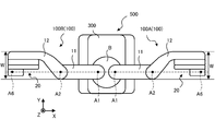
- FIG. 4A is a top view of the dual-arm robot 500
- FIG. 4B is a top view showing a posture in which the elevating arm 20 shown in FIG. 1 is opposed to each other.
- the dual-arm robot 500 includes a robot 100A corresponding to the left arm, a robot 100B corresponding to the right arm, a base portion B supporting the robot 100A and the robot 100B on the upper surface side, and a base portion B on the upper surface. It is provided with a trolley 300 that is supported on the side.
- the second horizontal arm 12 is supported on the upper surface side of the first horizontal arm 11.
- the second horizontal arm 12 is less likely to interfere with the base portion B than when the second horizontal arm 12 is arranged on the lower surface side of the first horizontal arm 11. Therefore, the substantially movable range of the second horizontal arm 12 can be widened.
- the dolly 300 has a built-in controller 600 that controls the operations of the robot 100A and the robot 100B. Further, the carriage 300 is provided with a plurality of wheels 310 and a plurality of legs 320 on the bottom surface side, respectively. When the trolley 300 is provided with the wheels 310, for example, the installation position can be easily moved by the manual operation of a worker, and when the legs 320 are provided, the installation position can be easily fixed.
- controller 600 is shown as an example of the equipment incorporated in the trolley 300 in FIG. 3A, various devices such as the end effector 200 and the sensor substrate attached to the dual-arm robot 500 are incorporated in the trolley 300. May be good. By doing so, obstacles around the dual-arm robot 500 can be reduced, and the interference region of the dual-arm robot 500 can be efficiently reduced.
- controller 600 may be incorporated in the carriage 300.
- a controller 600 for the robot 100A and a controller 600 for the robot 100B may be provided, and each robot 100 (robot 100A and the robot 100B) may be operated in cooperation by communicating with each other.
- the controller 600 may be provided in a separate housing from the dual-arm robot 500.
- the base portion B and the carriage 300 are shown separately, but the base portion B may be configured as a part of the carriage 300.
- each of the second horizontal arms 12 of the pair of robots 100 (robot 100A and robot 100B) is curved in the horizontal direction, and the elevating arms 20 are arranged at the portions recessed by the curvature.
- the base portion B is arranged on a part of the upper surface of the carriage 300, and the leg portions 320 are arranged on the bottom surface.
- the wheel 310 shown in FIG. 3A is not shown in FIG. 3B because it is hidden by the carriage 300.
- the posture of the dual-arm robot 500 shown in FIG. 4A is a posture in which both arms (robot 100A and robot 100B) are opened to the left and right, and the posture shown in FIG. It is a posture that is closed forward.
- the description of the end effector 200 shown in FIG. 3A is omitted.
- the base portion B of the dual-arm robot 500 supports a pair of robots 100 (robot 100A and robot 100B) on the upper surface side so that the first axis A1 is parallel to each other.
- the bending directions of the second horizontal arm 12 are opposite to each other.
- the second horizontal arm 12 of the robot 100A which corresponds to the left arm, has a shape curved clockwise of the second axis A2.
- the second horizontal arm 12 of the robot 100B which corresponds to the right arm, has a shape curved counterclockwise of the second axis A2.
- the dual-arm robot 500 when the posture shown in FIG. 4A is taken, the dual-arm robot 500 includes the first axis A1, the second axis A2 and the sixth axis A6 of the robot 100A, and the first axis A1 and the second axis A2 of the robot 100B. And the sixth axis A6 can be made linear.
- the elevating arms 20 since each of the elevating arms 20 is contained in the region W, the elevating arms 20 do not interfere with each other even when the following "follow-up" posture is taken.
- each robot 100 (robot 100A and robot 100B) in the dual-arm robot 500 faces the elevating arms 20 and has a "tip axis" on a plane including the first axis A1 and the second axis A2. It is assumed that each of the postures includes. In this case, the robot 100A and the robot 100B have outer shapes that do not interfere with each other. As described above, the "tip axis" corresponds to the sixth axis A6.
- the arms do not interfere with each other so that the arms interfere with each other. Since it is not necessary to consider the limitation due to the above, the teaching of the robot 100 can be performed efficiently. In addition, since it becomes easy for both arms to take close postures, the work efficiency of the dual-arm robot 500 can be improved.
- the robot 100A and the robot 100B cooperate with each other to perform handling work while the long work is gripped by both end effectors 200, or the other end effector 200 moves to the work gripped by one end effector 200. Processing work can be performed.
- each end effector 200 can be used even when the dual-arm robot 500 takes the posture shown in FIG. 4B. It is preferable that the outer shapes do not interfere with each other.
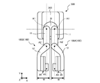
- FIG. 5 corresponds to a top view of the elevating arm 20
- FIGS. 6A and 6B correspond to a side view of the elevating arm 20
- FIG. 5 is an explanatory diagram showing the relationship between the arm length of the elevating arm 20 and the distance between the axes.
- FIG. 6A is a side view showing the basic posture of the elevating arm 20
- FIG. 6B is a side view showing the cooperative operation posture of the elevating arm 20. Note that, in FIGS. 5, 6A and 6B, the second horizontal arm 12 is shown by a broken line for reference.
- the elevating arm 20 has a first elevating arm 21 that swivels around the third axis A3 and a base end 22e side supported by the tip 21t side of the first elevating arm 21 and is parallel to the fourth axis A4.
- a second elevating arm 22 that swivels around the fifth axis A5 is provided.
- the elevating arm 20 includes a third elevating arm 23 that is supported on the tip 22t side of the second elevating arm 22 and swivels around the fifth axis A5 parallel to the fourth axis A4.
- first elevating arm 21, the second elevating arm 22, and the third elevating arm 23 are arranged in the order of the first elevating arm 21, the second elevating arm 22, and the third elevating arm 23 when viewed from the direction of the third axis A3. Has been done.
- the second distance L2 which is the distance between the fourth axis A4 and the fifth axis A5
- the first distance L1 which is the distance between the third axis A3 and the fourth axis A4.
- the second elevating arm 22 is in a basic posture (see FIG. 6A) in which the extending directions of the first elevating arm 21, the second elevating arm 22, and the third elevating arm 23 overlap each other when viewed from the direction of the third axis A3.
- the tip 22t has a length that does not exceed the base end 21e of the first elevating arm 21.
- the third elevating arm 23 has a length such that the base end 23e does not exceed the tip 22t of the second elevating arm 22.
- the elevating arm 20 is attached to the second horizontal arm 12 so that the base end 21e of the first elevating arm 21 does not exceed the tip 12t of the second horizontal arm 12. Note that FIG. 5 shows the base end 12e of the second horizontal arm 12 for reference.
- the base end 21e of the first lifting arm 21 and the tip 22t of the second lifting arm 22 are aligned, and the tip 21t of the first lifting arm 21 and the base end 22e of the second lifting arm 22 are aligned. It shows the case where and are aligned, that is, the case where the arm lengths of both arms are equal.
- the present invention is not limited to this, and the arm length of the second elevating arm 22 may be shorter than the arm length of the first elevating arm 21.
- FIG. 5 shows a case where the tip 22t of the second lifting arm 22 and the base end 23e of the third lifting arm 23 are aligned, but the base end 23e is closer to the fourth axis A4 than the tip 22t.
- the arm length of the third elevating arm 23 may be shortened so as to be. Since the main role of the third elevating arm 23 is to maintain the orientation of the sixth axis A6, as shown in FIG. 5, the tip 23t is set to the tip 22t rather than the base end 22e of the second elevating arm 22. By making it closer, the arm length can be made shorter than the arm length of the second elevating arm 22.
- the inter-axis distance is extended without extending the arm length of each arm, that is, the inter-axis distance is not made longer than the arm length of the first elevating arm 21.
- the third elevating arm 23 has a rotating portion 23r that rotates the end effector 200 (see FIG. 3A) around the sixth axis A6 perpendicular to the fifth axis A5.
- the sixth axis A6 is closer to the tip 22t of the second elevating arm 22 than the fifth axis A5 in a coordinated operation posture in which the end effector 200 is moved while maintaining the orientation of the sixth axis A6.
- FIG. 5 shows the shift amount of the sixth axis A6 from the fifth axis A5 as the third distance L3 for reference.
- the reachable range of the elevating arm 20 can be expanded. This is because the closer the sixth axis A6 is to the base end 23e of the third elevating arm 23, the more effectively the arm length of the second elevating arm 22 can be utilized.
- FIG. 5 is a top view of the elevating arm 20 in the basic posture (see FIG. 6A), but the orientation of the sixth axis A6 shown in FIG. 5 is maintained even in the coordinated operation posture. It can be said that the basic posture is one posture included in the cooperative movement posture.
- the side surface shape of the elevating arm 20 shown in FIG. 5 will be described with reference to FIG. 6A.
- the extension directions of the first elevating arm 21 and the second elevating arm 22 are horizontal.
- the third axis A3 and the fifth axis A5 overlap each other, and the third axis A3 and the fourth axis A4 and the fourth axis A4 and the fifth axis A5 are on the same horizontal plane.
- the direction of the sixth axis A6 axis is a vertical direction.
- the first elevating arm 21 and the tip end side of the second horizontal arm 12 are hidden behind the second elevating arm 22, but the outer shape of the first elevating arm 21 is that of the second elevating arm 22.
- the outer shape is the same, and the shape of the second horizontal arm 12 on the tip end side is the same as the shape of the second elevating arm 22 on the tip end side.
- the second axis A2 and the sixth axis A6 are parallel to each other, the second axis A2 and the sixth axis A6, the third axis A3, and the fourth axis A4.
- the fifth axis A5 is perpendicular.
- the extension direction of the third elevating arm 23 is the horizontal direction (direction parallel to the XZ plane) in the basic posture shown in FIG. 6A.
- FIG. 6B the posture of the elevating arm 20 in which the end effector 200 is moved above the basic posture shown in FIG. 6A is shown by a solid line, and the posture of the elevating arm 20 in which the end effector 200 is moved below the basic posture is shown by a solid line.
- the postures are indicated by broken lines.
- FIG. 6B shows the difference between the highest position and the lowest position of the end effector 200 as the ascending / descending range H.
- the postures of the first elevating arm 21 and the second elevating arm 22 shown in FIG. 6B are the postures shown for reference as an example, and do not need to be the postures as shown in FIG. 6B.
- the elevating arm 20 may be extended so that the extension directions of the first elevating arm 21 and the second elevating arm 22 are vertically oriented.
- the sixth axis A6 which is the rotation axis for rotating the end effector 200, is always oriented vertically. Coordinate with each other. Therefore, the posture in which the end effector 200 is moved while maintaining the orientation of the sixth axis A6 is collectively referred to as a cooperative movement posture.
- the ratio is "1: -2: 1" (however, "-(minus)" indicates the opposite direction).
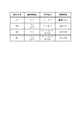
- FIG. 7 is an explanatory diagram showing the moving speed for each combination of the inter-axis distance ratio and the angular velocity ratio.
- FIG. 7 shows four examples of "combination examples” of "E1", “E2", “E3” and “E4". In addition, each item of “inter-axis distance ratio”, “angular velocity ratio”, and “moving speed” is shown for each "combination example”.
- the "axis-to-axis distance ratio” is the ratio of the first distance L1 and the second distance L2 shown in FIG.
- the “angular velocity ratio” is the ratio of the angular velocities corresponding to the turning of each arm around the third axis A3, the fourth axis A4, and the fifth axis A5 shown in FIG.
- the “moving speed” is a moving speed corresponding to the ascending / descending motion shown in FIG. 6B.
- "-(minus)" in “angular velocity ratio” indicates that it is in the reverse rotation direction with respect to the case where "-(minus)" is not added.
- E1 in the combination example is the above-mentioned general combination.
- the inter-axis distance ratio of the first distance L1 and the second distance L2 is “1: 1”
- the third axis A3, the fourth axis A4, and the fifth axis A5 (FIG. 5).
- the angular velocity ratio around is “1: -2: 1”.
- the moving speed of "E1" is "V1".
- V1 is used as a reference moving speed.
- E2 is a case where the angular velocity ratio around the third axis A3, the fourth axis A4, and the fifth axis A5 is the same as that of "E1”, but the second distance L2 is larger than the first distance L1 ( L2> L1) is shown.
- the inter-axis distance ratio of the first distance L1 and the second distance L2 is "1: j (however, j> 1)".
- the distance ratio between the axes is the same as that of "E1”, but the angular velocity ratio around the third axis A3, the fourth axis A4, and the fifth axis A5 is different from that of "E1". Is shown. Specifically, in “E3”, the angular velocity ratio around the third axis A3, the fourth axis A4, and the fifth axis A5 is "1: ⁇ k: k-1 (where k> 2)". The total of the three ratios is 0.
- E4 in the combination example shows a case where the inter-axis distance ratio and the angular velocity ratio are different from “E1" by combining “E2" and “E3".
- the distance ratio between axes is the same as that of "E2”
- the angular velocity ratio is the same as that of "E3”.
- the sixth height depends on the height in the ascending / descending range H (see FIG. 6B).
- the horizontal position of the axis A6 and the direction of the sixth axis A6 change.
- these deviations can be corrected by the operation of the robot 100 (see FIG. 1).
- the first axis A1 and the second axis A2 it is possible to correct the misalignment of the horizontal position of the sixth axis A6.
- the orientation deviation of the 6th axis A6 can be corrected.
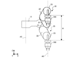
- FIGS. 8A and 8B are schematic views 1 and 2 showing an example of actuator arrangement.
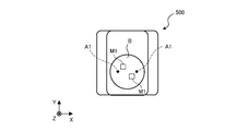
- FIG. 8A corresponds to a top view of the dual-arm robot 500 corresponding to FIG. 4B.
- FIG. 8B corresponds to a top view of the dual-arm robot 500 in which the first horizontal arm 11, the second horizontal arm 12, and the elevating arm 20 are removed from FIG. 8A.
- each second horizontal arm 12 of the dual-arm robot 500 has an actuator M2 and an actuator M3 built into each base end side.
- the actuator M2 and the actuator M3 are arranged on the proximal end side of the second horizontal arm 12 in this way, the moment of inertia associated with turning can be reduced, and the second horizontal arm 12 can be swiveled with a small torque. ..
- the actuator M2 is a drive source for a servomotor or the like, and provides a driving force for turning the second horizontal arm 12 around the second axis A2.
- the driving force of the actuator M2 is transmitted to the second shaft A2 via a transmission mechanism such as a gear mechanism or a pulley / belt mechanism.
- the second horizontal arm 12 turns with respect to the first horizontal arm 11.
- the actuator M3 is a drive source similar to the actuator M2, and provides a driving force for coordinating each arm of the elevating arm 20 around the third axis A3, the fourth axis A4, and the fifth axis A5 (see FIG. 6B). provide.
- the driving force of the actuator M3 is transmitted to the third axis A3 via a transmission mechanism such as a gear mechanism or a pulley / belt mechanism, and further transmitted to the fourth axis A4 via a transmission mechanism to further transmit the transmission mechanism. It is transmitted to the fifth axis A5 via.
- a transmission mechanism such as a gear mechanism or a pulley / belt mechanism
- the angular velocity ratios around the third axis A3, the fourth axis A4, and the fifth axis A5 are "1: -2: 1" or "1: -k: k-1" shown in FIG. k> 2) ”is set. If the posture of the sixth axis A6 is not maintained, "k> 0" may be set. Further, even when the posture of the sixth axis A6 is performed, it is not always necessary to set “k> 2”, and it is sufficient to set “k ⁇ 1”.
- each elevating arm 20 has an actuator M4 built-in.
- the actuator M4 is a drive source similar to the actuator M2 and the actuator M3, and provides a driving force for rotating the end effector 200 (see FIG. 3A) itself around the sixth axis A6.
- the driving force of the actuator M4 is transferred to the rotation axis of the end effector 200 via a transmission mechanism such as a gear mechanism or a pulley / belt mechanism. Be transmitted.
- a transmission mechanism such as a gear mechanism or a pulley / belt mechanism.
- the base portion B of the dual-arm robot 500 incorporates a pair of actuators M1.
- the actuator M1 is a drive source for a servomotor or the like, and provides a driving force for turning the first horizontal arm 11 around the first axis A1.
- the driving force of the actuator M1 is transmitted to the first shaft A1 via a transmission mechanism such as a gear mechanism or a pulley / belt mechanism.
- the first horizontal arm 11 turns with respect to the base portion B.
- each first axis A1 is provided at a position symmetrical with respect to the center of the circle, for example.
- each actuator M1 is provided at a position symmetrical with respect to the center of the circle, for example, so as to deviate from the line connecting the first axes A1.
- the actuator M1 by arranging the actuator M1 as described above, the height of the base portion B (thickness in the Z-axis direction) can be suppressed. That is, the height of the base portion B can be reduced.
- FIG. 8B a case where the first axes A1 and the actuators M1 are arranged at point-symmetrical positions with respect to the circular center is illustrated, but the positions are plane-symmetrical with respect to the plane parallel to the YZ plane. They may be arranged respectively, or the actuators M1 may be arranged at positions symmetrical with respect to a plane parallel to the XZ plane.
- the arm configuration having the relationship between the arm length and the distance between the axes shown in FIG. 5 has been described as an elevating arm 20 that expands and contracts in the vertical direction.
- the orientation of the third axis A3 on the elevating arm 20 is not limited to the horizontal orientation, and can be any orientation such as a vertical orientation.
- the elevating arm 20 itself may be used as the robot 20.
- the arm configuration of the elevating arm 20 When the arm configuration of the elevating arm 20 is used as the robot 20, for example, if the direction of the third axis A3 is vertical, it becomes a so-called horizontal arm. As described above, when the elevating arm 20 itself is widely used as the robot 20, the "first elevating arm 21", the “second elevating arm 22”, and the “third elevating arm 23” in the above description are referred to as “third elevating arm 23", respectively. It may be read as “first arm 21", "second arm 22", and "third arm 23".
- first turning axis A3 “first turning axis A3”
- second turning axis A4 “third turning axis A5"
- third turning axis A5 You can read it as it is. Then, the "elevation range” may be read as the “movement range”.
- the configuration of the robot 20 shown in FIG. 5 is as shown below.
- the robot 20 includes a first arm 21, a second arm 22, and a third arm 23.
- the first arm 21 swivels around the first swivel shaft A3.
- the base end 22e side of the second arm 22 is supported on the tip 21t side of the first arm 21, and the second arm 22 swivels around the second swivel shaft A4 parallel to the first swivel shaft A3.
- the third arm 23 is supported on the tip 22t side of the second arm 22 and swivels around the third swivel shaft A5 parallel to the second swivel shaft A4.
- first arm 21, the second arm 22, and the third arm 23 are arranged in the order of the first arm 21, the second arm 22, and the third arm 23 when viewed from the direction of the first turning axis A3.
- the second distance L2, which is the distance between the second swivel shaft A4 and the third swivel shaft A5, is larger than the first distance L1, which is the distance between the first swivel shaft A3 and the second swivel shaft A4.
- the tip 22t of the second arm 22 is the base of the first arm 21 in the basic posture in which the extension directions of the first arm 21, the second arm 22, and the third arm 23 overlap each other when viewed from the direction of the first turning axis A3.
- the length does not exceed the end 21e.
- the third arm 23 has a length that does not exceed the tip 22t of the second arm 22 in the above-mentioned basic posture.
- the third arm 23 includes a rotating portion 23r that rotates the end effector 200 around the first rotating shaft A6 that is perpendicular to the third swivel shaft A5.
- the first rotating shaft A6 is located closer to the tip 22t of the second arm 22 than the third turning shaft A5 in a coordinated operation posture in which the end effector 200 is moved while maintaining the orientation of the first rotating shaft A6.
- the angular velocity ratios of the first swivel axis A3, the second swivel axis A4, and the third swivel axis A5 in the robot 20 are "1: -k: k-1 (however, k> 2)" in the cooperative operation posture. is there.
- FIG. 9 is a schematic diagram showing an arrangement example of a plurality of robots.
- FIG. 9 shows a case where the robot 100A corresponding to the left arm of the dual-arm robot 500 shown in FIG. 4A or the like is arranged, the robot 100B corresponding to the right arm may be arranged.
- two rows of robots 100A are arranged on the installation table 700 in the direction along the Y axis.
- reference numerals such as 1 and 2 are added to the end of the robot 100A in the first row to describe the robot 100A1 and the robot 100A2.
- reference numerals such as 11 and 12 are added to the end of the robot 100A in the second row to describe the robot 100A11 and the robot 100A12.
- the second horizontal arm 12 (see FIG. 1) of the robot 100 is curved so that the elevating arm 20 (see FIG. 1) fits in the region created by the curvature. Have been placed. Therefore, interference with the adjacent robot 100 is unlikely to occur.
- the robots 100 in each row are parallel to the YZ plane. It can have a line-symmetrical configuration with respect to a plane.
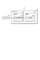
- FIG. 10 is a block diagram showing the configuration of the robot system 1.
- the robot system 1 includes a dual-arm robot 500 and a controller 600.
- the dual-arm robot 500 is connected to the controller 600.
- the controller 600 may be built in the dual-arm robot 500.
- the dual-arm robot 500 may be a single bowl robot (for example, the robot 100 in FIG. 1).
- the controller 600 includes a control unit 610 and a storage unit 620.
- the control unit 610 includes an operation control unit 610a.
- the storage unit 620 stores the teaching information 620a.
- FIG. 10 for simplification of the description, one dual-arm robot 500 and one controller 600 are shown, but the operation control of the plurality of dual-arm robots 500 is controlled by one controller. It may be performed by 600, or the operation control of one dual-arm robot 500 may be performed by a plurality of controllers 600. Further, when a plurality of controllers 600 are used, a higher-level controller that bundles each controller may be provided.
- the controller 600 includes, for example, a computer having a CPU (Central Processing Unit), a ROM (Read Only Memory), a RAM (Random Access Memory), an HDD (Hard Disk Drive), an input / output port, and various circuits. ..
- a computer having a CPU (Central Processing Unit), a ROM (Read Only Memory), a RAM (Random Access Memory), an HDD (Hard Disk Drive), an input / output port, and various circuits. ..
- the CPU of the computer functions as the operation control unit 610a of the control unit 610 by reading and executing the program stored in the ROM, for example.
- the operation control unit 610a can be configured by hardware such as an ASIC (Application Specific Integrated Circuit) or an FPGA (Field Programmable Gate Array).
- the storage unit 620 corresponds to, for example, a RAM or an HDD.
- the RAM or HDD can store the teaching information 620a.
- the controller 600 may acquire the above-mentioned program and various information via another computer or a portable recording medium connected by a wired or wireless network. Further, as described above, the controller 600 may be configured as a plurality of devices capable of communicating with each other, or may be configured as a hierarchical device capable of communicating with a higher or lower device.
- the control unit 610 controls the operation of the dual-arm robot 500.
- the control unit 610 may also perform a process of synchronizing the controllers 600.
- the motion control unit 610a operates the dual-arm robot 500 based on the teaching information 620a.
- the motion control unit 610a improves the motion accuracy of the dual arm robot 500 by performing feedback control while using the encoder value in the actuator such as the motor which is the power source of the dual arm robot 500.
- the teaching information 620a is information including a "job" that is created at the teaching stage of teaching the operation to the dual-arm robot 500 and is a program that defines the operation path of the dual-arm robot 500. As shown in FIG. 4 and the like, when both arms are arranged symmetrically, the teaching data for each arm can be shared or inverted. Therefore, according to the robot system 1, it is possible to reduce the labor and cost of generating the teaching information 620a including the teaching data.
- the robot 100 includes a first horizontal arm 11, a second horizontal arm 12, and an elevating arm 20.
- the first horizontal arm 11 turns around the first axis A1.
- the base end 12e side of the second horizontal arm 12 is supported by the tip end side of the first horizontal arm 11, and the second horizontal arm 12 rotates around the second axis A2 parallel to the first axis A1.
- the base end side of the elevating arm 20 is supported on the tip 12t side of the second horizontal arm 12, and the end effector 200 that can be attached to the tip side is raised and lowered.
- the second horizontal arm 12 is curved in any of the turning directions.
- the elevating arm 20 is arranged on the curved inner Si of the second horizontal arm 12 in a plan view.
- the elevating arm 20 on the curved inner Si of the curved second horizontal arm 12, the interference region of the robot 100 can be reduced.
- the robot 20 includes a first arm 21, a second arm 22, and a third arm 23.
- the first arm 21 swivels around the first swivel shaft A3.
- the base end 22e side of the second arm 22 is supported on the tip 21t side of the first arm 21, and the second arm 22 swivels around the second swivel shaft A4 parallel to the first swivel shaft A3.
- the third arm 23 is supported on the tip 22t side of the second arm 22 and swivels around the third swivel shaft A5 parallel to the second swivel shaft A4.
- the first arm 21, the second arm 22, and the third arm 23 are arranged in the order of the first arm 21, the second arm 22, and the third arm 23 when viewed from the direction of the first swivel axis A3.
- the second distance L2, which is the distance between the second swivel shaft A4 and the third swivel shaft A5, is larger than the first distance L1, which is the distance between the first swivel shaft A3 and the second swivel shaft A4.
- the tip 22t of the second arm 22 is the base of the first arm 21 in the basic posture in which the extension directions of the first arm 21, the second arm 22, and the third arm 23 overlap each other when viewed from the direction of the first turning axis A3.
- the length does not exceed the end 21e.
- the third arm 23 has a length that does not exceed the tip 22t of the second arm 22 in the basic posture.
- Robot system 10 Horizontal arm 11 1st horizontal arm 12 2nd horizontal arm 12e Base end 12t Tip 20
- Lifting arm (robot) 21 1st lifting arm (1st arm) 21e Base end 21t Tip 22
- Installation base A1 1st axis A2 2nd axis A3 3rd axis (1st swivel axis)
- A4 4th axis (2nd swivel axis) A5 5th axis (3rd turning axis)
- B Base part H Lifting range M1, M2, M3 Actuator Si Curved
Landscapes
- Engineering & Computer Science (AREA)
- Robotics (AREA)
- Mechanical Engineering (AREA)
- Manipulator (AREA)
Abstract
Un robot selon la présente invention est pourvu d'un premier bras horizontal, d'un second bras horizontal et d'un bras de levage et d'abaissement. Le premier bras horizontal tourne autour d'un premier axe. Le côté d'extrémité proximale du second bras horizontal est supporté sur le côté d'extrémité distale du premier bras horizontal, et le second bras horizontal tourne autour d'un second axe parallèle au premier axe. Le côté d'extrémité proximale du bras de levage et d'abaissement est supporté sur le côté d'extrémité distale du second bras horizontal, et le bras de levage et d'abaissement lève et abaisse un effecteur d'extrémité qui peut être fixé à son côté d'extrémité distale. Le second bras horizontal est incurvé dans l'une des directions de rotation. Le bras de levage et d'abaissement est disposé sur le côté interne de la courbure du second bras horizontal dans une vue en plan.
Priority Applications (2)
| Application Number | Priority Date | Filing Date | Title |
|---|---|---|---|
| JP2021565500A JP7268761B2 (ja) | 2019-12-16 | 2020-12-08 | ロボットおよび双腕ロボット |
| CN202080086576.8A CN114829079A (zh) | 2019-12-16 | 2020-12-08 | 机器人以及双臂机器人 |
Applications Claiming Priority (2)
| Application Number | Priority Date | Filing Date | Title |
|---|---|---|---|
| JP2019-226724 | 2019-12-16 | ||
| JP2019226724 | 2019-12-16 |
Publications (1)
| Publication Number | Publication Date |
|---|---|
| WO2021124986A1 true WO2021124986A1 (fr) | 2021-06-24 |
Family
ID=76476587
Family Applications (1)
| Application Number | Title | Priority Date | Filing Date |
|---|---|---|---|
| PCT/JP2020/045671 WO2021124986A1 (fr) | 2019-12-16 | 2020-12-08 | Robot et robot à double bras |
Country Status (3)
| Country | Link |
|---|---|
| JP (1) | JP7268761B2 (fr) |
| CN (1) | CN114829079A (fr) |
| WO (1) | WO2021124986A1 (fr) |
Citations (3)
| Publication number | Priority date | Publication date | Assignee | Title |
|---|---|---|---|---|
| JP2575133Y2 (ja) * | 1993-02-26 | 1998-06-25 | 株式会社ダイフク | アーム回動式作業装置 |
| JP2012254525A (ja) * | 2012-10-03 | 2012-12-27 | Seiko Epson Corp | 水平多関節型ロボット |
| JP2017188627A (ja) * | 2016-04-08 | 2017-10-12 | 株式会社安川電機 | 搬送システム、ロボットおよびロボットの制御方法 |
Family Cites Families (17)
| Publication number | Priority date | Publication date | Assignee | Title |
|---|---|---|---|---|
| JPS59146776A (ja) * | 1983-02-04 | 1984-08-22 | 神鋼電機株式会社 | 物品のパレタイズ用多関節ロボツト |
| JPS61100384A (ja) * | 1984-10-23 | 1986-05-19 | 株式会社東芝 | 水平多関節形ロボツト |
| DE3513705A1 (de) * | 1985-04-16 | 1986-10-23 | Manutec Gesellschaft für Automatisierungs- und Handhabungssysteme mbH, 8510 Fürth | Industrieroboter mit schwenkarm |
| JPS6411490U (fr) * | 1987-07-10 | 1989-01-20 | ||
| JPH033784A (ja) * | 1989-05-31 | 1991-01-09 | Pentel Kk | 多関節型ロボット |
| JPH0549289U (ja) * | 1991-12-03 | 1993-06-29 | 株式会社東芝 | 産業用ロボット |
| JPH07108476A (ja) * | 1993-10-12 | 1995-04-25 | Yamaha Motor Co Ltd | ロボットの直線方向作動装置 |
| JPH0890463A (ja) * | 1994-09-19 | 1996-04-09 | Kansai Electric Power Co Inc:The | 水平多関節形ロボット |
| JP2005236218A (ja) * | 2004-02-23 | 2005-09-02 | Rorze Corp | 半導体ウエハの搬送ロボット、及びそれを備えた処理装置 |
| JP3920274B2 (ja) | 2004-03-08 | 2007-05-30 | ファナック株式会社 | 成形品取出装置及び該装置を搭載した成形機 |
| JP2006007332A (ja) * | 2004-06-22 | 2006-01-12 | Matsushita Electric Ind Co Ltd | 産業用ロボット |
| JP2007083316A (ja) | 2005-09-16 | 2007-04-05 | Yushin Precision Equipment Co Ltd | 関節構造の駆動機構 |
| JP5177835B2 (ja) | 2007-04-27 | 2013-04-10 | 株式会社安川電機 | 双腕型ロボットマニピュレータ |
| JP2013233653A (ja) * | 2013-08-30 | 2013-11-21 | Seiko Epson Corp | 水平多関節型ロボット |
| JP6677190B2 (ja) | 2017-02-09 | 2020-04-08 | 株式会社安川電機 | 塗装システムおよび固定式操作ロボット |
| JP2018187749A (ja) | 2017-05-11 | 2018-11-29 | セイコーエプソン株式会社 | ロボット |
| JP2019000912A (ja) | 2017-06-09 | 2019-01-10 | 川崎重工業株式会社 | ロボットアームの手首及び双腕ロボット |
-
2020
- 2020-12-08 JP JP2021565500A patent/JP7268761B2/ja active Active
- 2020-12-08 WO PCT/JP2020/045671 patent/WO2021124986A1/fr active Application Filing
- 2020-12-08 CN CN202080086576.8A patent/CN114829079A/zh active Pending
Patent Citations (3)
| Publication number | Priority date | Publication date | Assignee | Title |
|---|---|---|---|---|
| JP2575133Y2 (ja) * | 1993-02-26 | 1998-06-25 | 株式会社ダイフク | アーム回動式作業装置 |
| JP2012254525A (ja) * | 2012-10-03 | 2012-12-27 | Seiko Epson Corp | 水平多関節型ロボット |
| JP2017188627A (ja) * | 2016-04-08 | 2017-10-12 | 株式会社安川電機 | 搬送システム、ロボットおよびロボットの制御方法 |
Also Published As
| Publication number | Publication date |
|---|---|
| JP7268761B2 (ja) | 2023-05-08 |
| JPWO2021124986A1 (fr) | 2021-06-24 |
| CN114829079A (zh) | 2022-07-29 |
Similar Documents
| Publication | Publication Date | Title |
|---|---|---|
| JP3999712B2 (ja) | 多関節ロボット | |
| JP6051021B2 (ja) | 産業用ロボットおよび産業用ロボットの制御方法 | |
| US10580681B2 (en) | Robotic apparatus and method for transport of a workpiece | |
| JP6630727B2 (ja) | 水平多関節ロボット | |
| KR20210129240A (ko) | 다수의 엔드-이펙터로써 재료를 핸들링하는 방법 및 장치 | |
| JP5120258B2 (ja) | ワーク搬送装置 | |
| US20180065254A1 (en) | Robot system | |
| KR20130056344A (ko) | 7축 다관절 로봇의 제어방법, 제어 프로그램 및 로봇 제어장치 | |
| WO2017043420A1 (fr) | Dispositif de travail composite utilisant un dispositif de commande de liaison | |
| CN113631324A (zh) | 多主体控制器和机器人 | |
| US11491645B2 (en) | Scissor linkage design and method of operation | |
| WO2021124986A1 (fr) | Robot et robot à double bras | |
| WO2019163997A1 (fr) | Dispositif de travail utilisant un mécanisme de liaison parallèle et procédé de commande de celui-ci | |
| US11745342B2 (en) | Manipulator for finishing work, and control method therefor | |
| JP6057284B2 (ja) | 多関節ロボット及び半導体ウェハ搬送装置 | |
| US20230311333A1 (en) | Painting robot and painting system | |
| JP6863397B2 (ja) | ロボット | |
| EP3868520B1 (fr) | Système de robots | |
| US20210008710A1 (en) | Mobile robot | |
| JP4268035B2 (ja) | 産業用ロボットおよびその制御方法 | |
| EP4173774A1 (fr) | Robot de peinture et système de peinture | |
| KR101655344B1 (ko) | 산업용 로봇용 엔드 이펙터 | |
| JP7481941B2 (ja) | ロボットおよびロボットシステム | |
| JP5976580B2 (ja) | リンク作動装置の制御装置 | |
| TWI623397B (zh) | Horizontal articulated robot |
Legal Events
| Date | Code | Title | Description |
|---|---|---|---|
| 121 | Ep: the epo has been informed by wipo that ep was designated in this application |
Ref document number: 20902141 Country of ref document: EP Kind code of ref document: A1 |
|
| ENP | Entry into the national phase |
Ref document number: 2021565500 Country of ref document: JP Kind code of ref document: A |
|
| NENP | Non-entry into the national phase |
Ref country code: DE |
|
| 122 | Ep: pct application non-entry in european phase |
Ref document number: 20902141 Country of ref document: EP Kind code of ref document: A1 |