WO2021124986A1 - Robot and double-arm robot - Google Patents
Robot and double-arm robot Download PDFInfo
- Publication number
- WO2021124986A1 WO2021124986A1 PCT/JP2020/045671 JP2020045671W WO2021124986A1 WO 2021124986 A1 WO2021124986 A1 WO 2021124986A1 JP 2020045671 W JP2020045671 W JP 2020045671W WO 2021124986 A1 WO2021124986 A1 WO 2021124986A1
- Authority
- WO
- WIPO (PCT)
- Prior art keywords
- arm
- axis
- robot
- elevating
- end side
- Prior art date
Links
Images


Classifications
-
- B—PERFORMING OPERATIONS; TRANSPORTING
- B25—HAND TOOLS; PORTABLE POWER-DRIVEN TOOLS; MANIPULATORS
- B25J—MANIPULATORS; CHAMBERS PROVIDED WITH MANIPULATION DEVICES
- B25J9/00—Programme-controlled manipulators
- B25J9/06—Programme-controlled manipulators characterised by multi-articulated arms
Definitions
- the disclosed embodiment relates to a robot and a dual-arm robot.
- SCARA robot horizontal articulated robot
- each arm of a dual-arm SCARA robot is provided with a slide mechanism that moves up and down vertically to improve accessibility to an object (see, for example, Patent Document 1).
- the above-mentioned conventional technology has a problem that interference between robot arms and obstacles is likely to occur, that is, an interference area is likely to be widened.
- an interference area is likely to be widened.
- the interference area is wide, the actual operation area in which the work can be performed without interference is narrowed in the original movable area of the robot, and as a result, the work efficiency by the robot is lowered.
- such a problem is not limited to a double-armed robot, but is a problem that also occurs in a so-called single-armed robot. Further, such a problem occurs in both a robot that expands and contracts in the horizontal direction and a robot that expands and contracts in the vertical direction.
- One aspect of the embodiment is to provide a robot and a dual-arm robot capable of reducing an interference region.
- the robot includes a first horizontal arm, a second horizontal arm, and an elevating arm.
- the first horizontal arm turns around the first axis.
- the base end side of the second horizontal arm is supported by the tip end side of the first horizontal arm, and the second horizontal arm swivels around a second axis parallel to the first axis.
- the base end side of the elevating arm is supported on the tip end side of the second horizontal arm, and the end effector that can be attached to the tip end side is lifted and lowered.
- the second horizontal arm is curved in either turning direction.
- the elevating arm is arranged inside the curve in the second horizontal arm in a plan view.
- the robot includes a first arm, a second arm, and a third arm.
- the first arm swivels around the first swivel axis.
- the base end side of the second arm is supported by the tip end side of the first arm, and the second arm swivels around a second swivel shaft parallel to the first swivel shaft.
- the third arm is supported on the tip end side of the second arm and swivels around a third swivel shaft parallel to the second swivel shaft.
- the first arm, the second arm, and the third arm are arranged in the order of the first arm, the second arm, and the third arm when viewed from the direction of the first turning axis.
- the second distance which is the inter-axis distance between the second swivel shaft and the third swivel shaft
- the first distance which is the inter-axis distance between the first swivel shaft and the second swivel shaft.
- FIG. 1 is a top view of the robot according to the embodiment.
- FIG. 2 is a top view showing the curved shape of the second horizontal arm.
- FIG. 3A is a front view of the dual-arm robot.
- FIG. 3B is a perspective view of the dual-arm robot.
- FIG. 4A is a top view of the dual-arm robot.
- FIG. 4B is a top view showing a posture in which the elevating arms are opposed to each other.
- FIG. 5 is an explanatory diagram showing the relationship between the arm length of the elevating arm and the distance between the axes.
- FIG. 6A is a side view showing the basic posture of the elevating arm.
- FIG. 6B is a side view showing the cooperative operation posture of the elevating arm.
- FIG. 7 is an explanatory diagram showing the moving speed for each combination of the inter-axis distance ratio and the angular velocity ratio.
- FIG. 8A is a schematic view No. 1 showing an example of actuator arrangement.
- FIG. 8B is a schematic view 2 showing an example of actuator arrangement.
- FIG. 9 is a schematic diagram showing an arrangement example of a plurality of robots.
- FIG. 10 is a block diagram showing a configuration of a robot system.
- the robot is equipped with an end effector which is a tool for gripping the work with a claw
- the end effector may be a suction type tool, and a sealing material is applied, painted, and welded. It may be a tool that performs such as.
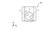
- FIG. 1 is a top view of the robot 100 according to the embodiment.
- FIG. 1 shows a three-dimensional Cartesian coordinate system in which the XY plane corresponds to the horizontal plane, including the Z axis whose vertical upward direction is the positive direction, for the sake of clarity.
- Cartesian coordinate system may also be shown in other drawings used in the following description.
- the robot 100 includes a first horizontal arm 11 and a second horizontal arm 12, which are horizontal arms 10, and an elevating arm 20.
- An end effector 200 can be attached to the tip end side of the elevating arm 20.
- the elevating arm 20 includes a plurality of arms and each arm swivels around a horizontal axis to expand and contract to elevate and retract the end effector 200 will be described.
- the present invention is not limited to this, and the elevating arm 20 may be a slide mechanism for vertically elevating or lowering, or an arm group including such a slide mechanism.
- the base end side of the first horizontal arm 11 is attached to, for example, the base portion B.
- the circular base portion B is shown in FIG. 1 in a plan view, the three-dimensional shape of the base portion B is not limited to a columnar shape, and may be any shape such as a rectangular parallelepiped shape or an elliptical columnar shape. Further, the base portion B may be a support member such as a floor.
- the first horizontal arm 11 is supported on the base end side by a support member such as a base portion B, and swivels around a vertically oriented first axis A1.
- the base end side of the second horizontal arm 12 is supported by the tip end side of the first horizontal arm 11, and the second horizontal arm 12 swivels around the second axis A2 parallel to the first axis A1.
- the elevating arm 20 is supported on the base end side on the tip end side of the second horizontal arm 12, and raises and lowers the end effector 200 that can be attached to the tip end side.
- the second horizontal arm 12 is curved in any turning direction around the first axis A1 which is the vertical axis, and the elevating arm 20 is curved inside Si in the second horizontal arm 12 in a plan view. Be placed.
- the opposite side of the curved inner Si is referred to as the curved outer So.
- FIG. 1 shows a case where the second horizontal arm 12 has a shape curved clockwise of the second axis A2, it may have a shape curved counterclockwise.
- the elevating arm 20 on the curved inner Si of the second horizontal arm 12, which is a curved arm, the region of the curved inner Si that does not easily interfere with obstacles or the like can be effectively utilized, and the robot can be effectively utilized. It is possible to reduce the interference region where 100 interferes with obstacles and the like.
- the elevating arm 20 includes a first elevating arm 21, a second elevating arm 22, and a third elevating arm 23.
- the base end side of the first elevating arm 21 is supported by the tip end side of the second horizontal arm 12, and the first elevating arm 21 swivels around a third axis A3 perpendicular to the first axis A1.
- the base end side of the second elevating arm 22 is supported by the tip end side of the first elevating arm 21, and the second elevating arm 22 swivels around the fourth axis A4 parallel to the third axis A3.
- the third elevating arm 23 is supported on the tip end side of the second elevating arm 22 and swivels around the fifth axis A5 parallel to the fourth axis A4.
- the third elevating arm 23 has a rotating portion 23r that rotates the end effector 200 around the sixth axis A6 perpendicular to the fifth axis A5.
- the rotating portion 23r may be provided on the bottom surface side of the third elevating arm 23, or may be provided on the side surface side excluding the second elevating arm 22 side.
- the robot 100 is an articulated robot having 6 axes of 1st axis A1 to 6th axis A6.
- the end effector 200 keeps the direction of the sixth axis A6, which is the "tip axis". Can be moved to any three-dimensional position.
- the elevating arm 20 by forming the elevating arm 20 into a three-arm configuration, it is possible to sufficiently secure the elevating range of the elevating operation.
- the detailed relationship between the length of each arm and the distance between the axes of the elevating arm 20 will be described later with reference to FIG.
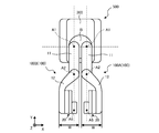
- FIG. 2 is a top view showing the curved shape of the second horizontal arm 12. Note that FIG. 2 corresponds to the second horizontal arm 12 and the elevating arm 20 of the robot 100 shown in FIG.
- the second horizontal arm 12 has a shape in which the base end side and the tip end side of the curved outer So are linear, respectively, and the base end side and the tip end side are smoothly connected by a curve in a plan view.
- the base end side and the tip end side of the curved inner Si are also linear, respectively, and have a shape in which the base end side and the tip end side are smoothly connected by a curve, similarly to the curved outer side So.
- the elevating arm 20 is arranged in a straight line portion on the tip side of the curved inner Si.
- FIG. 2 shows a case where the tip side of the curved outer So and the tip side of the curved inner Si are parallel, it is not always necessary that they are parallel.
- first virtual tangent line TL1 the virtual tangent line in contact with the tip end side of the curved outer So in the second horizontal arm 12
- second virtual tangent TL2 The farthest virtual tangent is referred to as “second virtual tangent TL2”.
- area W the area sandwiched between the first virtual tangent line TL1 and the second virtual tangent line TL2
- the entire elevating arm 20 fits in the region W sandwiched between the first virtual tangent line TL1 and the second virtual tangent line TL2. That is, the second horizontal arm 12 is curved so that the entire elevating arm 20 fits in the region W.
- the second horizontal arm 12 is curved so that the entire elevating arm 20 fits in the region W.
- FIG. 2 a case where a part of the end effector 200 protrudes from the area W is shown, but the outer shape of the end effector 200 may be shaped so as to fit in the area W. By doing so, the interference region due to the end effector 200 can be further reduced.
- the robot 100 also reduces the interference region by accommodating a cable such as a cable connected to the end effector 200 inside the housing, and thus the above-mentioned curvature.
- the interference region can be efficiently reduced together with the reduction of the interference region due to the shape.
- the side surface shape of the elevating arm 20 shown in FIG. 2 will be described later with reference to FIGS. 6A and 6B.
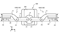
- FIG. 3A is a front view of the dual-arm robot 500
- FIG. 3B is a perspective view of the dual-arm robot 500. Note that FIG. 3B corresponds to a view of the dual-arm robot 500 viewed from diagonally above.
- FIG. 4A is a top view of the dual-arm robot 500
- FIG. 4B is a top view showing a posture in which the elevating arm 20 shown in FIG. 1 is opposed to each other.
- the dual-arm robot 500 includes a robot 100A corresponding to the left arm, a robot 100B corresponding to the right arm, a base portion B supporting the robot 100A and the robot 100B on the upper surface side, and a base portion B on the upper surface. It is provided with a trolley 300 that is supported on the side.
- the second horizontal arm 12 is supported on the upper surface side of the first horizontal arm 11.
- the second horizontal arm 12 is less likely to interfere with the base portion B than when the second horizontal arm 12 is arranged on the lower surface side of the first horizontal arm 11. Therefore, the substantially movable range of the second horizontal arm 12 can be widened.
- the dolly 300 has a built-in controller 600 that controls the operations of the robot 100A and the robot 100B. Further, the carriage 300 is provided with a plurality of wheels 310 and a plurality of legs 320 on the bottom surface side, respectively. When the trolley 300 is provided with the wheels 310, for example, the installation position can be easily moved by the manual operation of a worker, and when the legs 320 are provided, the installation position can be easily fixed.
- controller 600 is shown as an example of the equipment incorporated in the trolley 300 in FIG. 3A, various devices such as the end effector 200 and the sensor substrate attached to the dual-arm robot 500 are incorporated in the trolley 300. May be good. By doing so, obstacles around the dual-arm robot 500 can be reduced, and the interference region of the dual-arm robot 500 can be efficiently reduced.
- controller 600 may be incorporated in the carriage 300.
- a controller 600 for the robot 100A and a controller 600 for the robot 100B may be provided, and each robot 100 (robot 100A and the robot 100B) may be operated in cooperation by communicating with each other.
- the controller 600 may be provided in a separate housing from the dual-arm robot 500.
- the base portion B and the carriage 300 are shown separately, but the base portion B may be configured as a part of the carriage 300.
- each of the second horizontal arms 12 of the pair of robots 100 (robot 100A and robot 100B) is curved in the horizontal direction, and the elevating arms 20 are arranged at the portions recessed by the curvature.
- the base portion B is arranged on a part of the upper surface of the carriage 300, and the leg portions 320 are arranged on the bottom surface.
- the wheel 310 shown in FIG. 3A is not shown in FIG. 3B because it is hidden by the carriage 300.
- the posture of the dual-arm robot 500 shown in FIG. 4A is a posture in which both arms (robot 100A and robot 100B) are opened to the left and right, and the posture shown in FIG. It is a posture that is closed forward.
- the description of the end effector 200 shown in FIG. 3A is omitted.
- the base portion B of the dual-arm robot 500 supports a pair of robots 100 (robot 100A and robot 100B) on the upper surface side so that the first axis A1 is parallel to each other.
- the bending directions of the second horizontal arm 12 are opposite to each other.
- the second horizontal arm 12 of the robot 100A which corresponds to the left arm, has a shape curved clockwise of the second axis A2.
- the second horizontal arm 12 of the robot 100B which corresponds to the right arm, has a shape curved counterclockwise of the second axis A2.
- the dual-arm robot 500 when the posture shown in FIG. 4A is taken, the dual-arm robot 500 includes the first axis A1, the second axis A2 and the sixth axis A6 of the robot 100A, and the first axis A1 and the second axis A2 of the robot 100B. And the sixth axis A6 can be made linear.
- the elevating arms 20 since each of the elevating arms 20 is contained in the region W, the elevating arms 20 do not interfere with each other even when the following "follow-up" posture is taken.
- each robot 100 (robot 100A and robot 100B) in the dual-arm robot 500 faces the elevating arms 20 and has a "tip axis" on a plane including the first axis A1 and the second axis A2. It is assumed that each of the postures includes. In this case, the robot 100A and the robot 100B have outer shapes that do not interfere with each other. As described above, the "tip axis" corresponds to the sixth axis A6.
- the arms do not interfere with each other so that the arms interfere with each other. Since it is not necessary to consider the limitation due to the above, the teaching of the robot 100 can be performed efficiently. In addition, since it becomes easy for both arms to take close postures, the work efficiency of the dual-arm robot 500 can be improved.
- the robot 100A and the robot 100B cooperate with each other to perform handling work while the long work is gripped by both end effectors 200, or the other end effector 200 moves to the work gripped by one end effector 200. Processing work can be performed.
- each end effector 200 can be used even when the dual-arm robot 500 takes the posture shown in FIG. 4B. It is preferable that the outer shapes do not interfere with each other.
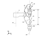
- FIG. 5 corresponds to a top view of the elevating arm 20
- FIGS. 6A and 6B correspond to a side view of the elevating arm 20
- FIG. 5 is an explanatory diagram showing the relationship between the arm length of the elevating arm 20 and the distance between the axes.
- FIG. 6A is a side view showing the basic posture of the elevating arm 20
- FIG. 6B is a side view showing the cooperative operation posture of the elevating arm 20. Note that, in FIGS. 5, 6A and 6B, the second horizontal arm 12 is shown by a broken line for reference.
- the elevating arm 20 has a first elevating arm 21 that swivels around the third axis A3 and a base end 22e side supported by the tip 21t side of the first elevating arm 21 and is parallel to the fourth axis A4.
- a second elevating arm 22 that swivels around the fifth axis A5 is provided.
- the elevating arm 20 includes a third elevating arm 23 that is supported on the tip 22t side of the second elevating arm 22 and swivels around the fifth axis A5 parallel to the fourth axis A4.
- first elevating arm 21, the second elevating arm 22, and the third elevating arm 23 are arranged in the order of the first elevating arm 21, the second elevating arm 22, and the third elevating arm 23 when viewed from the direction of the third axis A3. Has been done.
- the second distance L2 which is the distance between the fourth axis A4 and the fifth axis A5
- the first distance L1 which is the distance between the third axis A3 and the fourth axis A4.
- the second elevating arm 22 is in a basic posture (see FIG. 6A) in which the extending directions of the first elevating arm 21, the second elevating arm 22, and the third elevating arm 23 overlap each other when viewed from the direction of the third axis A3.
- the tip 22t has a length that does not exceed the base end 21e of the first elevating arm 21.
- the third elevating arm 23 has a length such that the base end 23e does not exceed the tip 22t of the second elevating arm 22.
- the elevating arm 20 is attached to the second horizontal arm 12 so that the base end 21e of the first elevating arm 21 does not exceed the tip 12t of the second horizontal arm 12. Note that FIG. 5 shows the base end 12e of the second horizontal arm 12 for reference.
- the base end 21e of the first lifting arm 21 and the tip 22t of the second lifting arm 22 are aligned, and the tip 21t of the first lifting arm 21 and the base end 22e of the second lifting arm 22 are aligned. It shows the case where and are aligned, that is, the case where the arm lengths of both arms are equal.
- the present invention is not limited to this, and the arm length of the second elevating arm 22 may be shorter than the arm length of the first elevating arm 21.
- FIG. 5 shows a case where the tip 22t of the second lifting arm 22 and the base end 23e of the third lifting arm 23 are aligned, but the base end 23e is closer to the fourth axis A4 than the tip 22t.
- the arm length of the third elevating arm 23 may be shortened so as to be. Since the main role of the third elevating arm 23 is to maintain the orientation of the sixth axis A6, as shown in FIG. 5, the tip 23t is set to the tip 22t rather than the base end 22e of the second elevating arm 22. By making it closer, the arm length can be made shorter than the arm length of the second elevating arm 22.
- the inter-axis distance is extended without extending the arm length of each arm, that is, the inter-axis distance is not made longer than the arm length of the first elevating arm 21.
- the third elevating arm 23 has a rotating portion 23r that rotates the end effector 200 (see FIG. 3A) around the sixth axis A6 perpendicular to the fifth axis A5.
- the sixth axis A6 is closer to the tip 22t of the second elevating arm 22 than the fifth axis A5 in a coordinated operation posture in which the end effector 200 is moved while maintaining the orientation of the sixth axis A6.
- FIG. 5 shows the shift amount of the sixth axis A6 from the fifth axis A5 as the third distance L3 for reference.
- the reachable range of the elevating arm 20 can be expanded. This is because the closer the sixth axis A6 is to the base end 23e of the third elevating arm 23, the more effectively the arm length of the second elevating arm 22 can be utilized.
- FIG. 5 is a top view of the elevating arm 20 in the basic posture (see FIG. 6A), but the orientation of the sixth axis A6 shown in FIG. 5 is maintained even in the coordinated operation posture. It can be said that the basic posture is one posture included in the cooperative movement posture.
- the side surface shape of the elevating arm 20 shown in FIG. 5 will be described with reference to FIG. 6A.
- the extension directions of the first elevating arm 21 and the second elevating arm 22 are horizontal.
- the third axis A3 and the fifth axis A5 overlap each other, and the third axis A3 and the fourth axis A4 and the fourth axis A4 and the fifth axis A5 are on the same horizontal plane.
- the direction of the sixth axis A6 axis is a vertical direction.
- the first elevating arm 21 and the tip end side of the second horizontal arm 12 are hidden behind the second elevating arm 22, but the outer shape of the first elevating arm 21 is that of the second elevating arm 22.
- the outer shape is the same, and the shape of the second horizontal arm 12 on the tip end side is the same as the shape of the second elevating arm 22 on the tip end side.
- the second axis A2 and the sixth axis A6 are parallel to each other, the second axis A2 and the sixth axis A6, the third axis A3, and the fourth axis A4.
- the fifth axis A5 is perpendicular.
- the extension direction of the third elevating arm 23 is the horizontal direction (direction parallel to the XZ plane) in the basic posture shown in FIG. 6A.
- FIG. 6B the posture of the elevating arm 20 in which the end effector 200 is moved above the basic posture shown in FIG. 6A is shown by a solid line, and the posture of the elevating arm 20 in which the end effector 200 is moved below the basic posture is shown by a solid line.
- the postures are indicated by broken lines.
- FIG. 6B shows the difference between the highest position and the lowest position of the end effector 200 as the ascending / descending range H.
- the postures of the first elevating arm 21 and the second elevating arm 22 shown in FIG. 6B are the postures shown for reference as an example, and do not need to be the postures as shown in FIG. 6B.
- the elevating arm 20 may be extended so that the extension directions of the first elevating arm 21 and the second elevating arm 22 are vertically oriented.
- the sixth axis A6 which is the rotation axis for rotating the end effector 200, is always oriented vertically. Coordinate with each other. Therefore, the posture in which the end effector 200 is moved while maintaining the orientation of the sixth axis A6 is collectively referred to as a cooperative movement posture.
- the ratio is "1: -2: 1" (however, "-(minus)" indicates the opposite direction).
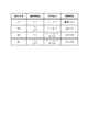
- FIG. 7 is an explanatory diagram showing the moving speed for each combination of the inter-axis distance ratio and the angular velocity ratio.
- FIG. 7 shows four examples of "combination examples” of "E1", “E2", “E3” and “E4". In addition, each item of “inter-axis distance ratio”, “angular velocity ratio”, and “moving speed” is shown for each "combination example”.
- the "axis-to-axis distance ratio” is the ratio of the first distance L1 and the second distance L2 shown in FIG.
- the “angular velocity ratio” is the ratio of the angular velocities corresponding to the turning of each arm around the third axis A3, the fourth axis A4, and the fifth axis A5 shown in FIG.
- the “moving speed” is a moving speed corresponding to the ascending / descending motion shown in FIG. 6B.
- "-(minus)" in “angular velocity ratio” indicates that it is in the reverse rotation direction with respect to the case where "-(minus)" is not added.
- E1 in the combination example is the above-mentioned general combination.
- the inter-axis distance ratio of the first distance L1 and the second distance L2 is “1: 1”
- the third axis A3, the fourth axis A4, and the fifth axis A5 (FIG. 5).
- the angular velocity ratio around is “1: -2: 1”.
- the moving speed of "E1" is "V1".
- V1 is used as a reference moving speed.
- E2 is a case where the angular velocity ratio around the third axis A3, the fourth axis A4, and the fifth axis A5 is the same as that of "E1”, but the second distance L2 is larger than the first distance L1 ( L2> L1) is shown.
- the inter-axis distance ratio of the first distance L1 and the second distance L2 is "1: j (however, j> 1)".
- the distance ratio between the axes is the same as that of "E1”, but the angular velocity ratio around the third axis A3, the fourth axis A4, and the fifth axis A5 is different from that of "E1". Is shown. Specifically, in “E3”, the angular velocity ratio around the third axis A3, the fourth axis A4, and the fifth axis A5 is "1: ⁇ k: k-1 (where k> 2)". The total of the three ratios is 0.
- E4 in the combination example shows a case where the inter-axis distance ratio and the angular velocity ratio are different from “E1" by combining “E2" and “E3".
- the distance ratio between axes is the same as that of "E2”
- the angular velocity ratio is the same as that of "E3”.
- the sixth height depends on the height in the ascending / descending range H (see FIG. 6B).
- the horizontal position of the axis A6 and the direction of the sixth axis A6 change.
- these deviations can be corrected by the operation of the robot 100 (see FIG. 1).
- the first axis A1 and the second axis A2 it is possible to correct the misalignment of the horizontal position of the sixth axis A6.
- the orientation deviation of the 6th axis A6 can be corrected.
- FIGS. 8A and 8B are schematic views 1 and 2 showing an example of actuator arrangement.
- FIG. 8A corresponds to a top view of the dual-arm robot 500 corresponding to FIG. 4B.
- FIG. 8B corresponds to a top view of the dual-arm robot 500 in which the first horizontal arm 11, the second horizontal arm 12, and the elevating arm 20 are removed from FIG. 8A.
- each second horizontal arm 12 of the dual-arm robot 500 has an actuator M2 and an actuator M3 built into each base end side.
- the actuator M2 and the actuator M3 are arranged on the proximal end side of the second horizontal arm 12 in this way, the moment of inertia associated with turning can be reduced, and the second horizontal arm 12 can be swiveled with a small torque. ..
- the actuator M2 is a drive source for a servomotor or the like, and provides a driving force for turning the second horizontal arm 12 around the second axis A2.
- the driving force of the actuator M2 is transmitted to the second shaft A2 via a transmission mechanism such as a gear mechanism or a pulley / belt mechanism.
- the second horizontal arm 12 turns with respect to the first horizontal arm 11.
- the actuator M3 is a drive source similar to the actuator M2, and provides a driving force for coordinating each arm of the elevating arm 20 around the third axis A3, the fourth axis A4, and the fifth axis A5 (see FIG. 6B). provide.
- the driving force of the actuator M3 is transmitted to the third axis A3 via a transmission mechanism such as a gear mechanism or a pulley / belt mechanism, and further transmitted to the fourth axis A4 via a transmission mechanism to further transmit the transmission mechanism. It is transmitted to the fifth axis A5 via.
- a transmission mechanism such as a gear mechanism or a pulley / belt mechanism
- the angular velocity ratios around the third axis A3, the fourth axis A4, and the fifth axis A5 are "1: -2: 1" or "1: -k: k-1" shown in FIG. k> 2) ”is set. If the posture of the sixth axis A6 is not maintained, "k> 0" may be set. Further, even when the posture of the sixth axis A6 is performed, it is not always necessary to set “k> 2”, and it is sufficient to set “k ⁇ 1”.
- each elevating arm 20 has an actuator M4 built-in.
- the actuator M4 is a drive source similar to the actuator M2 and the actuator M3, and provides a driving force for rotating the end effector 200 (see FIG. 3A) itself around the sixth axis A6.
- the driving force of the actuator M4 is transferred to the rotation axis of the end effector 200 via a transmission mechanism such as a gear mechanism or a pulley / belt mechanism. Be transmitted.
- a transmission mechanism such as a gear mechanism or a pulley / belt mechanism.
- the base portion B of the dual-arm robot 500 incorporates a pair of actuators M1.
- the actuator M1 is a drive source for a servomotor or the like, and provides a driving force for turning the first horizontal arm 11 around the first axis A1.
- the driving force of the actuator M1 is transmitted to the first shaft A1 via a transmission mechanism such as a gear mechanism or a pulley / belt mechanism.
- the first horizontal arm 11 turns with respect to the base portion B.
- each first axis A1 is provided at a position symmetrical with respect to the center of the circle, for example.
- each actuator M1 is provided at a position symmetrical with respect to the center of the circle, for example, so as to deviate from the line connecting the first axes A1.
- the actuator M1 by arranging the actuator M1 as described above, the height of the base portion B (thickness in the Z-axis direction) can be suppressed. That is, the height of the base portion B can be reduced.
- FIG. 8B a case where the first axes A1 and the actuators M1 are arranged at point-symmetrical positions with respect to the circular center is illustrated, but the positions are plane-symmetrical with respect to the plane parallel to the YZ plane. They may be arranged respectively, or the actuators M1 may be arranged at positions symmetrical with respect to a plane parallel to the XZ plane.
- the arm configuration having the relationship between the arm length and the distance between the axes shown in FIG. 5 has been described as an elevating arm 20 that expands and contracts in the vertical direction.
- the orientation of the third axis A3 on the elevating arm 20 is not limited to the horizontal orientation, and can be any orientation such as a vertical orientation.
- the elevating arm 20 itself may be used as the robot 20.
- the arm configuration of the elevating arm 20 When the arm configuration of the elevating arm 20 is used as the robot 20, for example, if the direction of the third axis A3 is vertical, it becomes a so-called horizontal arm. As described above, when the elevating arm 20 itself is widely used as the robot 20, the "first elevating arm 21", the “second elevating arm 22”, and the “third elevating arm 23” in the above description are referred to as “third elevating arm 23", respectively. It may be read as “first arm 21", "second arm 22", and "third arm 23".
- first turning axis A3 “first turning axis A3”
- second turning axis A4 “third turning axis A5"
- third turning axis A5 You can read it as it is. Then, the "elevation range” may be read as the “movement range”.
- the configuration of the robot 20 shown in FIG. 5 is as shown below.
- the robot 20 includes a first arm 21, a second arm 22, and a third arm 23.
- the first arm 21 swivels around the first swivel shaft A3.
- the base end 22e side of the second arm 22 is supported on the tip 21t side of the first arm 21, and the second arm 22 swivels around the second swivel shaft A4 parallel to the first swivel shaft A3.
- the third arm 23 is supported on the tip 22t side of the second arm 22 and swivels around the third swivel shaft A5 parallel to the second swivel shaft A4.
- first arm 21, the second arm 22, and the third arm 23 are arranged in the order of the first arm 21, the second arm 22, and the third arm 23 when viewed from the direction of the first turning axis A3.
- the second distance L2, which is the distance between the second swivel shaft A4 and the third swivel shaft A5, is larger than the first distance L1, which is the distance between the first swivel shaft A3 and the second swivel shaft A4.
- the tip 22t of the second arm 22 is the base of the first arm 21 in the basic posture in which the extension directions of the first arm 21, the second arm 22, and the third arm 23 overlap each other when viewed from the direction of the first turning axis A3.
- the length does not exceed the end 21e.
- the third arm 23 has a length that does not exceed the tip 22t of the second arm 22 in the above-mentioned basic posture.
- the third arm 23 includes a rotating portion 23r that rotates the end effector 200 around the first rotating shaft A6 that is perpendicular to the third swivel shaft A5.
- the first rotating shaft A6 is located closer to the tip 22t of the second arm 22 than the third turning shaft A5 in a coordinated operation posture in which the end effector 200 is moved while maintaining the orientation of the first rotating shaft A6.
- the angular velocity ratios of the first swivel axis A3, the second swivel axis A4, and the third swivel axis A5 in the robot 20 are "1: -k: k-1 (however, k> 2)" in the cooperative operation posture. is there.
- FIG. 9 is a schematic diagram showing an arrangement example of a plurality of robots.
- FIG. 9 shows a case where the robot 100A corresponding to the left arm of the dual-arm robot 500 shown in FIG. 4A or the like is arranged, the robot 100B corresponding to the right arm may be arranged.
- two rows of robots 100A are arranged on the installation table 700 in the direction along the Y axis.
- reference numerals such as 1 and 2 are added to the end of the robot 100A in the first row to describe the robot 100A1 and the robot 100A2.
- reference numerals such as 11 and 12 are added to the end of the robot 100A in the second row to describe the robot 100A11 and the robot 100A12.
- the second horizontal arm 12 (see FIG. 1) of the robot 100 is curved so that the elevating arm 20 (see FIG. 1) fits in the region created by the curvature. Have been placed. Therefore, interference with the adjacent robot 100 is unlikely to occur.
- the robots 100 in each row are parallel to the YZ plane. It can have a line-symmetrical configuration with respect to a plane.
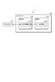
- FIG. 10 is a block diagram showing the configuration of the robot system 1.
- the robot system 1 includes a dual-arm robot 500 and a controller 600.
- the dual-arm robot 500 is connected to the controller 600.
- the controller 600 may be built in the dual-arm robot 500.
- the dual-arm robot 500 may be a single bowl robot (for example, the robot 100 in FIG. 1).
- the controller 600 includes a control unit 610 and a storage unit 620.
- the control unit 610 includes an operation control unit 610a.
- the storage unit 620 stores the teaching information 620a.
- FIG. 10 for simplification of the description, one dual-arm robot 500 and one controller 600 are shown, but the operation control of the plurality of dual-arm robots 500 is controlled by one controller. It may be performed by 600, or the operation control of one dual-arm robot 500 may be performed by a plurality of controllers 600. Further, when a plurality of controllers 600 are used, a higher-level controller that bundles each controller may be provided.
- the controller 600 includes, for example, a computer having a CPU (Central Processing Unit), a ROM (Read Only Memory), a RAM (Random Access Memory), an HDD (Hard Disk Drive), an input / output port, and various circuits. ..
- a computer having a CPU (Central Processing Unit), a ROM (Read Only Memory), a RAM (Random Access Memory), an HDD (Hard Disk Drive), an input / output port, and various circuits. ..
- the CPU of the computer functions as the operation control unit 610a of the control unit 610 by reading and executing the program stored in the ROM, for example.
- the operation control unit 610a can be configured by hardware such as an ASIC (Application Specific Integrated Circuit) or an FPGA (Field Programmable Gate Array).
- the storage unit 620 corresponds to, for example, a RAM or an HDD.
- the RAM or HDD can store the teaching information 620a.
- the controller 600 may acquire the above-mentioned program and various information via another computer or a portable recording medium connected by a wired or wireless network. Further, as described above, the controller 600 may be configured as a plurality of devices capable of communicating with each other, or may be configured as a hierarchical device capable of communicating with a higher or lower device.
- the control unit 610 controls the operation of the dual-arm robot 500.
- the control unit 610 may also perform a process of synchronizing the controllers 600.
- the motion control unit 610a operates the dual-arm robot 500 based on the teaching information 620a.
- the motion control unit 610a improves the motion accuracy of the dual arm robot 500 by performing feedback control while using the encoder value in the actuator such as the motor which is the power source of the dual arm robot 500.
- the teaching information 620a is information including a "job" that is created at the teaching stage of teaching the operation to the dual-arm robot 500 and is a program that defines the operation path of the dual-arm robot 500. As shown in FIG. 4 and the like, when both arms are arranged symmetrically, the teaching data for each arm can be shared or inverted. Therefore, according to the robot system 1, it is possible to reduce the labor and cost of generating the teaching information 620a including the teaching data.
- the robot 100 includes a first horizontal arm 11, a second horizontal arm 12, and an elevating arm 20.
- the first horizontal arm 11 turns around the first axis A1.
- the base end 12e side of the second horizontal arm 12 is supported by the tip end side of the first horizontal arm 11, and the second horizontal arm 12 rotates around the second axis A2 parallel to the first axis A1.
- the base end side of the elevating arm 20 is supported on the tip 12t side of the second horizontal arm 12, and the end effector 200 that can be attached to the tip side is raised and lowered.
- the second horizontal arm 12 is curved in any of the turning directions.
- the elevating arm 20 is arranged on the curved inner Si of the second horizontal arm 12 in a plan view.
- the elevating arm 20 on the curved inner Si of the curved second horizontal arm 12, the interference region of the robot 100 can be reduced.
- the robot 20 includes a first arm 21, a second arm 22, and a third arm 23.
- the first arm 21 swivels around the first swivel shaft A3.
- the base end 22e side of the second arm 22 is supported on the tip 21t side of the first arm 21, and the second arm 22 swivels around the second swivel shaft A4 parallel to the first swivel shaft A3.
- the third arm 23 is supported on the tip 22t side of the second arm 22 and swivels around the third swivel shaft A5 parallel to the second swivel shaft A4.
- the first arm 21, the second arm 22, and the third arm 23 are arranged in the order of the first arm 21, the second arm 22, and the third arm 23 when viewed from the direction of the first swivel axis A3.
- the second distance L2, which is the distance between the second swivel shaft A4 and the third swivel shaft A5, is larger than the first distance L1, which is the distance between the first swivel shaft A3 and the second swivel shaft A4.
- the tip 22t of the second arm 22 is the base of the first arm 21 in the basic posture in which the extension directions of the first arm 21, the second arm 22, and the third arm 23 overlap each other when viewed from the direction of the first turning axis A3.
- the length does not exceed the end 21e.
- the third arm 23 has a length that does not exceed the tip 22t of the second arm 22 in the basic posture.
- Robot system 10 Horizontal arm 11 1st horizontal arm 12 2nd horizontal arm 12e Base end 12t Tip 20
- Lifting arm (robot) 21 1st lifting arm (1st arm) 21e Base end 21t Tip 22
- Installation base A1 1st axis A2 2nd axis A3 3rd axis (1st swivel axis)
- A4 4th axis (2nd swivel axis) A5 5th axis (3rd turning axis)
- B Base part H Lifting range M1, M2, M3 Actuator Si Curved
Abstract
A robot according to the present invention is provided with a first horizontal arm, a second horizontal arm, and a raising and lowering arm. The first horizontal arm rotates about a first axis. The proximal-end side of the second horizontal arm is supported on the distal-end side of the first horizontal arm, and the second horizontal arm rotates about a second axis parallel to the first axis. The proximal-end side of the raising and lowering arm is supported on the distal-end side of the second horizontal arm, and the raising and lowering arm raises and lowers an end effector that can be attached to the distal-end side thereof. The second horizontal arm is curved in one of the rotation directions. The raising and lowering arm is arranged on the inner side of the curvature of the second horizontal arm in plan view.
Description
開示の実施形態は、ロボットおよび双腕ロボットに関する。
The disclosed embodiment relates to a robot and a dual-arm robot.
従来、対象物の搬送や組み立てに水平多関節ロボット(スカラロボット)を用いることが知られている。また、作業効率を向上させる観点から、スカラロボットを一対、すなわち、2つ備える双腕スカラロボットも提案されている。
Conventionally, it is known that a horizontal articulated robot (SCARA robot) is used for transporting and assembling an object. Further, from the viewpoint of improving work efficiency, a dual-arm SCARA robot having a pair of SCARA robots, that is, two SCARA robots has also been proposed.
また、双腕スカラロボットの各腕に鉛直向きに昇降するスライド機構を設け、対象物へのアクセス性を向上させる技術も提案されている(たとえば、特許文献1参照)。
In addition, a technique has been proposed in which each arm of a dual-arm SCARA robot is provided with a slide mechanism that moves up and down vertically to improve accessibility to an object (see, for example, Patent Document 1).
しかしながら、上記した従来技術には、ロボットの腕同士や障害物との干渉が発生しやすい、すなわち、干渉領域が広くなりやすいという問題がある。このように、干渉領域が広いと、ロボットの本来の可動領域のうち干渉せずに作業を行うことができる実動作領域は狭められてしまい、結果的にロボットによる作業効率が低下する。
However, the above-mentioned conventional technology has a problem that interference between robot arms and obstacles is likely to occur, that is, an interference area is likely to be widened. As described above, when the interference area is wide, the actual operation area in which the work can be performed without interference is narrowed in the original movable area of the robot, and as a result, the work efficiency by the robot is lowered.
なお、かかる課題は、双腕ロボットに限らず、いわゆる単腕ロボットにも同様に発生する課題である。また、かかる課題は、水平向きに伸縮するロボットにも、鉛直向きに伸縮するロボットにも同様に発生する課題である。
It should be noted that such a problem is not limited to a double-armed robot, but is a problem that also occurs in a so-called single-armed robot. Further, such a problem occurs in both a robot that expands and contracts in the horizontal direction and a robot that expands and contracts in the vertical direction.
実施形態の一態様は、干渉領域を低減することができるロボットおよび双腕ロボットを提供することを目的とする。
One aspect of the embodiment is to provide a robot and a dual-arm robot capable of reducing an interference region.
実施形態の一態様に係るロボットは、第1水平アームと、第2水平アームと、昇降アームとを備える。第1水平アームは、第1軸まわりに旋回する。第2水平アームは、第1水平アームの先端側に基端側が支持され、第1軸と平行な第2軸まわりに旋回する。昇降アームは、第2水平アームの先端側に基端側が支持され、先端側に取り付け可能なエンドエフェクタを昇降させる。第2水平アームは、いずれかの旋回向きに湾曲している。昇降アームは、平面視において、第2水平アームにおける湾曲内側に配置される。
The robot according to one aspect of the embodiment includes a first horizontal arm, a second horizontal arm, and an elevating arm. The first horizontal arm turns around the first axis. The base end side of the second horizontal arm is supported by the tip end side of the first horizontal arm, and the second horizontal arm swivels around a second axis parallel to the first axis. The base end side of the elevating arm is supported on the tip end side of the second horizontal arm, and the end effector that can be attached to the tip end side is lifted and lowered. The second horizontal arm is curved in either turning direction. The elevating arm is arranged inside the curve in the second horizontal arm in a plan view.
実施形態の他の態様に係るロボットは、第1アームと、第2アームと、第3アームとを備える。第1アームは、第1旋回軸まわりに旋回する。第2アームは、第1アームの先端側に基端側が支持され、第1旋回軸と平行な第2旋回軸まわりに旋回する。第3アームは、第2アームの先端側に支持され、第2旋回軸と平行な第3旋回軸まわりに旋回する。第1アーム、第2アームおよび第3アームは、第1旋回軸の向きからみて第1アーム、第2アームおよび第3アームの順序で配置されている。第2旋回軸と第3旋回軸との軸間距離である第2距離は、第1旋回軸と第2旋回軸との軸間距離である第1距離よりも大きい。第2アームは、第1アーム、第2アームおよび第3アームのそれぞれの延伸向きが第1旋回軸の向きからみて重なった基本姿勢では、先端が第1アームの基端を超えない長さである。第3アームは、基本姿勢では、第2アームの先端を超えない長さである。
The robot according to another aspect of the embodiment includes a first arm, a second arm, and a third arm. The first arm swivels around the first swivel axis. The base end side of the second arm is supported by the tip end side of the first arm, and the second arm swivels around a second swivel shaft parallel to the first swivel shaft. The third arm is supported on the tip end side of the second arm and swivels around a third swivel shaft parallel to the second swivel shaft. The first arm, the second arm, and the third arm are arranged in the order of the first arm, the second arm, and the third arm when viewed from the direction of the first turning axis. The second distance, which is the inter-axis distance between the second swivel shaft and the third swivel shaft, is larger than the first distance, which is the inter-axis distance between the first swivel shaft and the second swivel shaft. In the basic posture in which the extension directions of the first arm, the second arm, and the third arm overlap each other when viewed from the direction of the first turning axis, the tip of the second arm has a length that does not exceed the base end of the first arm. is there. The third arm has a length that does not exceed the tip of the second arm in the basic posture.
実施形態の一態様によれば、干渉領域を低減することが可能となるロボットおよび双腕ロボットを提供することができる。
According to one aspect of the embodiment, it is possible to provide a robot and a dual-arm robot capable of reducing the interference region.
以下、添付図面を参照して、本願の開示するロボットおよび双腕ロボットの実施形態を詳細に説明する。なお、以下に示す実施形態によりこの発明が限定されるものではない。また、以下では、ロボットが、ワークを爪で把持するツールであるエンドエフェクタを装着した場合について説明するが、エンドエフェクタは、吸着式のツールであってもよく、シール材の塗布、塗装、溶接などを行うツールであってもよい。
Hereinafter, embodiments of the robot and the dual-arm robot disclosed in the present application will be described in detail with reference to the attached drawings. The present invention is not limited to the embodiments shown below. Further, in the following, the case where the robot is equipped with an end effector which is a tool for gripping the work with a claw will be described. However, the end effector may be a suction type tool, and a sealing material is applied, painted, and welded. It may be a tool that performs such as.
また、以下に示す実施形態では、「直交」、「垂直」、「平行」、「水平」、「鉛直」あるいは「対称」といった表現を用いるが、厳密にこれらの状態を満たすことを要しない。すなわち、上記した各表現は、製造精度、設置精度、処理制度、検出精度などのずれを許容するものとする。
Further, in the embodiments shown below, expressions such as "orthogonal", "vertical", "parallel", "horizontal", "vertical" or "symmetrical" are used, but it is not necessary to strictly satisfy these states. That is, each of the above expressions allows for deviations in manufacturing accuracy, installation accuracy, processing system, detection accuracy, and the like.
まず、実施形態に係るロボット100について図1を用いて説明する。図1は、実施形態に係るロボット100の上面図である。なお、図1には、説明をわかりやすくするために、鉛直上向きが正方向であるZ軸を含み、XY平面が水平面に対応する3次元の直交座標系を示している。かかる直交座標系は、以下の説明で用いる他の図面においても示す場合がある。
First, the robot 100 according to the embodiment will be described with reference to FIG. FIG. 1 is a top view of the robot 100 according to the embodiment. Note that FIG. 1 shows a three-dimensional Cartesian coordinate system in which the XY plane corresponds to the horizontal plane, including the Z axis whose vertical upward direction is the positive direction, for the sake of clarity. Such a Cartesian coordinate system may also be shown in other drawings used in the following description.
図1に示すように、ロボット100は、水平アーム10である第1水平アーム11および第2水平アーム12と、昇降アーム20とを備える。昇降アーム20の先端側にはエンドエフェクタ200が取り付け可能である。
As shown in FIG. 1, the robot 100 includes a first horizontal arm 11 and a second horizontal arm 12, which are horizontal arms 10, and an elevating arm 20. An end effector 200 can be attached to the tip end side of the elevating arm 20.
なお、以下では、昇降アーム20が複数のアームを含み、各アームが水平軸まわりに旋回して伸縮することでエンドエフェクタ200を昇降させる場合について説明する。しかしながら、これに限らず、昇降アーム20を、鉛直向きに昇降するスライド機構としたり、かかるスライド機構を含むアーム群としたりすることとしてもよい。
In the following, a case where the elevating arm 20 includes a plurality of arms and each arm swivels around a horizontal axis to expand and contract to elevate and retract the end effector 200 will be described. However, the present invention is not limited to this, and the elevating arm 20 may be a slide mechanism for vertically elevating or lowering, or an arm group including such a slide mechanism.
また、第1水平アーム11の基端側は、たとえば、ベース部Bに取り付けられる。なお、図1には平面視において円形のベース部Bを示したが、ベース部Bの立体形状は、円柱状に限らず、直方体状や楕円柱状など任意の形状であってもよい。また、ベース部Bは、床などの支持部材であってもよい。
Further, the base end side of the first horizontal arm 11 is attached to, for example, the base portion B. Although the circular base portion B is shown in FIG. 1 in a plan view, the three-dimensional shape of the base portion B is not limited to a columnar shape, and may be any shape such as a rectangular parallelepiped shape or an elliptical columnar shape. Further, the base portion B may be a support member such as a floor.
図1に示したように、第1水平アーム11は、たとえば、ベース部Bなどの支持部材に基端側が支持され、鉛直向きの第1軸A1まわりに旋回する。第2水平アーム12は、第1水平アーム11の先端側に基端側が支持され、第1軸A1と平行な第2軸A2まわりに旋回する。昇降アーム20は、第2水平アーム12の先端側に基端側が支持され、先端側に取り付け可能なエンドエフェクタ200を昇降させる。
As shown in FIG. 1, the first horizontal arm 11 is supported on the base end side by a support member such as a base portion B, and swivels around a vertically oriented first axis A1. The base end side of the second horizontal arm 12 is supported by the tip end side of the first horizontal arm 11, and the second horizontal arm 12 swivels around the second axis A2 parallel to the first axis A1. The elevating arm 20 is supported on the base end side on the tip end side of the second horizontal arm 12, and raises and lowers the end effector 200 that can be attached to the tip end side.
ここで、第2水平アーム12は、鉛直軸である第1軸A1まわりのいずれかの旋回向きに湾曲しており、昇降アーム20は、平面視において、第2水平アーム12における湾曲内側Siに配置される。ここで、湾曲内側Siの反対側を湾曲外側Soと呼ぶこととする。なお、図1では、第2水平アーム12が、第2軸A2の時計回りに湾曲した形状である場合を示したが、反時計回りに湾曲した形状としてもよい。
Here, the second horizontal arm 12 is curved in any turning direction around the first axis A1 which is the vertical axis, and the elevating arm 20 is curved inside Si in the second horizontal arm 12 in a plan view. Be placed. Here, the opposite side of the curved inner Si is referred to as the curved outer So. Although FIG. 1 shows a case where the second horizontal arm 12 has a shape curved clockwise of the second axis A2, it may have a shape curved counterclockwise.
このように、昇降アーム20を、湾曲するアームである第2水平アーム12の湾曲内側Siに配置することで、障害物等に干渉しにくい湾曲内側Siの領域を有効活用することができ、ロボット100が障害物等に干渉する干渉領域を低減することが可能となる。
In this way, by arranging the elevating arm 20 on the curved inner Si of the second horizontal arm 12, which is a curved arm, the region of the curved inner Si that does not easily interfere with obstacles or the like can be effectively utilized, and the robot can be effectively utilized. It is possible to reduce the interference region where 100 interferes with obstacles and the like.
以下では、図1に示した昇降アーム20の構成についてさらに詳細に説明する。昇降アーム20は、第1昇降アーム21と、第2昇降アーム22と、第3昇降アーム23とを備える。第1昇降アーム21は、第2水平アーム12の先端側に基端側が支持され、第1軸A1と垂直な第3軸A3まわりに旋回する。
Hereinafter, the configuration of the elevating arm 20 shown in FIG. 1 will be described in more detail. The elevating arm 20 includes a first elevating arm 21, a second elevating arm 22, and a third elevating arm 23. The base end side of the first elevating arm 21 is supported by the tip end side of the second horizontal arm 12, and the first elevating arm 21 swivels around a third axis A3 perpendicular to the first axis A1.
第2昇降アーム22は、第1昇降アーム21の先端側に基端側が支持され、第3軸A3と平行な第4軸A4まわりに旋回する。第3昇降アーム23は、第2昇降アーム22の先端側に支持され、第4軸A4と平行な第5軸A5まわりに旋回する。
The base end side of the second elevating arm 22 is supported by the tip end side of the first elevating arm 21, and the second elevating arm 22 swivels around the fourth axis A4 parallel to the third axis A3. The third elevating arm 23 is supported on the tip end side of the second elevating arm 22 and swivels around the fifth axis A5 parallel to the fourth axis A4.
また、第3昇降アーム23は、第5軸A5と垂直な第6軸A6まわりにエンドエフェクタ200を回転させる回転部23rを有する。なお、回転部23rは、第3昇降アーム23の底面側に設けられてもよく、第2昇降アーム22側を除いた側面側にも設けられてもよい。
Further, the third elevating arm 23 has a rotating portion 23r that rotates the end effector 200 around the sixth axis A6 perpendicular to the fifth axis A5. The rotating portion 23r may be provided on the bottom surface side of the third elevating arm 23, or may be provided on the side surface side excluding the second elevating arm 22 side.
図1に示したように、ロボット100は、第1軸A1~第6軸A6の6軸を有する多関節ロボットである。このように、水平アーム10(第1水平アーム11および第2水平アーム12)と、昇降アーム20とを組み合わせることで、「先端軸」である第6軸A6の向きを保持したままエンドエフェクタ200を任意の3次元位置に移動させることができる。
As shown in FIG. 1, the robot 100 is an articulated robot having 6 axes of 1st axis A1 to 6th axis A6. In this way, by combining the horizontal arm 10 (the first horizontal arm 11 and the second horizontal arm 12) and the elevating arm 20, the end effector 200 keeps the direction of the sixth axis A6, which is the "tip axis". Can be moved to any three-dimensional position.
また、図1に示したように、昇降アーム20を3アーム構成とすることで、昇降動作の昇降範囲を十分に確保することができる。なお、昇降アーム20における各アーム長や軸間距離の詳細な関係については、図5を用いて後述することとする。
Further, as shown in FIG. 1, by forming the elevating arm 20 into a three-arm configuration, it is possible to sufficiently secure the elevating range of the elevating operation. The detailed relationship between the length of each arm and the distance between the axes of the elevating arm 20 will be described later with reference to FIG.
次に、湾曲アームである第2水平アーム12の具体的な湾曲形状について図2を用いて説明する。図2は、第2水平アーム12の湾曲形状を示す上面図である。なお、図2は、図1に示したロボット100の第2水平アーム12および昇降アーム20に相当する。
Next, a specific curved shape of the second horizontal arm 12, which is a curved arm, will be described with reference to FIG. FIG. 2 is a top view showing the curved shape of the second horizontal arm 12. Note that FIG. 2 corresponds to the second horizontal arm 12 and the elevating arm 20 of the robot 100 shown in FIG.
図2に示すように、第2水平アーム12は、平面視において、湾曲外側Soの基端側および先端側がそれぞれ直線状であり、基端側と先端側とを滑らかに曲線でつないだ形状を有している。また、湾曲内側Siの基端側および先端側もそれぞれ直線状であり、湾曲外側Soと同様に、基端側と先端側とを滑らかに曲線でつないだ形状を有している。
As shown in FIG. 2, the second horizontal arm 12 has a shape in which the base end side and the tip end side of the curved outer So are linear, respectively, and the base end side and the tip end side are smoothly connected by a curve in a plan view. Have. Further, the base end side and the tip end side of the curved inner Si are also linear, respectively, and have a shape in which the base end side and the tip end side are smoothly connected by a curve, similarly to the curved outer side So.
また、昇降アーム20は、湾曲内側Siにおける先端側における直線部分に配置される。なお、図2には、湾曲外側Soの先端側と、湾曲内側Siの先端側とが平行である場合を示したが、必ずしも平行であることを要しない。
Further, the elevating arm 20 is arranged in a straight line portion on the tip side of the curved inner Si. Although FIG. 2 shows a case where the tip side of the curved outer So and the tip side of the curved inner Si are parallel, it is not always necessary that they are parallel.
ここで、第2水平アーム12における湾曲外側Soの先端側に接する仮想接線を「第1仮想接線TL1」とし、第2水平アーム12に接する仮想接線のうち第1仮想接線TL1に対して平行かつ最も離れた仮想接線を「第2仮想接線TL2」とする。そして、第1仮想接線TL1と、第2仮想接線TL2とに挟まれた領域を「領域W」とする。
Here, the virtual tangent line in contact with the tip end side of the curved outer So in the second horizontal arm 12 is referred to as "first virtual tangent line TL1", and the virtual tangent line in contact with the second horizontal arm 12 is parallel to the first virtual tangent line TL1. The farthest virtual tangent is referred to as "second virtual tangent TL2". Then, the area sandwiched between the first virtual tangent line TL1 and the second virtual tangent line TL2 is referred to as "area W".
この場合、図2に示したように、昇降アーム20は、第1仮想接線TL1と、第2仮想接線TL2とに挟まれた領域Wに全体が収まる。つまり、第2水平アーム12は、昇降アーム20全体が領域Wに収まる程度に湾曲している。このように、アームの湾曲によって生じた領域W内に昇降アーム20を収容することで、昇降アーム20と障害物等との干渉を抑制することができ、干渉領域を効率よく低減することが可能となる。なお、湾曲内側Siの基端側(昇降アーム20が存在しない領域)には、各種センサや配線などを第2水平アーム12へ外付けすることもでき、領域Wを有効活用することが可能となる。
In this case, as shown in FIG. 2, the entire elevating arm 20 fits in the region W sandwiched between the first virtual tangent line TL1 and the second virtual tangent line TL2. That is, the second horizontal arm 12 is curved so that the entire elevating arm 20 fits in the region W. By accommodating the elevating arm 20 in the region W generated by the curvature of the arm in this way, it is possible to suppress the interference between the elevating arm 20 and an obstacle or the like, and it is possible to efficiently reduce the interference region. Will be. It should be noted that various sensors, wiring, etc. can be externally attached to the second horizontal arm 12 on the base end side of the curved inner Si (the area where the elevating arm 20 does not exist), and the area W can be effectively used. Become.
ここで、図2では、エンドエフェクタ200の一部が領域Wからはみ出している場合を示したが、エンドエフェクタ200の外形を領域W内に収まる形状にすることとしてもよい。このようにすることで、エンドエフェクタ200による干渉領域をさらに低減することができる。
Here, in FIG. 2, a case where a part of the end effector 200 protrudes from the area W is shown, but the outer shape of the end effector 200 may be shaped so as to fit in the area W. By doing so, the interference region due to the end effector 200 can be further reduced.
また、図1および図2に示したように、ロボット100は、エンドエフェクタ200に接続するケーブルなどのケーブルを筐体の内部に収容することでも干渉領域の低減を図っているので、上記した湾曲形状による干渉領域の低減とあわせて干渉領域を効率よく低減することができる。なお、図2に示した昇降アーム20の側面形状については、図6Aおよび図6Bを用いて後述する。
Further, as shown in FIGS. 1 and 2, the robot 100 also reduces the interference region by accommodating a cable such as a cable connected to the end effector 200 inside the housing, and thus the above-mentioned curvature. The interference region can be efficiently reduced together with the reduction of the interference region due to the shape. The side surface shape of the elevating arm 20 shown in FIG. 2 will be described later with reference to FIGS. 6A and 6B.
次に、図1に示したロボット100を一対備える双腕ロボット500について図3A、図3B、図4Aおよび図4Bを用いて説明する。図3Aは、双腕ロボット500の正面図であり、図3Bは、双腕ロボット500の斜視図である。なお、図3Bは、双腕ロボット500を斜め上方からみた図に相当する。図4Aは、双腕ロボット500の上面図であり、図4Bは、図1に示した昇降アーム20を対向させた姿勢を示す上面図である。
Next, a dual-arm robot 500 including a pair of robots 100 shown in FIG. 1 will be described with reference to FIGS. 3A, 3B, 4A, and 4B. FIG. 3A is a front view of the dual-arm robot 500, and FIG. 3B is a perspective view of the dual-arm robot 500. Note that FIG. 3B corresponds to a view of the dual-arm robot 500 viewed from diagonally above. FIG. 4A is a top view of the dual-arm robot 500, and FIG. 4B is a top view showing a posture in which the elevating arm 20 shown in FIG. 1 is opposed to each other.
まず、双腕ロボット500の正面形状について説明する。図3Aに示すように、双腕ロボット500は、左腕に相当するロボット100Aと、右腕に相当するロボット100Bと、ロボット100Aおよびロボット100Bを上面側で支持するベース部Bと、ベース部Bを上面側で支持する台車300とを備える。
First, the front shape of the dual-arm robot 500 will be described. As shown in FIG. 3A, the dual-arm robot 500 includes a robot 100A corresponding to the left arm, a robot 100B corresponding to the right arm, a base portion B supporting the robot 100A and the robot 100B on the upper surface side, and a base portion B on the upper surface. It is provided with a trolley 300 that is supported on the side.
図3Aに示したように、一対のロボット100(ロボット100Aおよびロボット100B)の各々は、第2水平アーム12が、第1水平アーム11の上面側で支持される。このようにすることで、第2水平アーム12を第1水平アーム11の下面側に配置する場合よりも、第2水平アーム12がベース部Bと干渉しにくい。したがって、第2水平アーム12の実質的な可動範囲を広くすることができる。
As shown in FIG. 3A, in each of the pair of robots 100 (robot 100A and robot 100B), the second horizontal arm 12 is supported on the upper surface side of the first horizontal arm 11. By doing so, the second horizontal arm 12 is less likely to interfere with the base portion B than when the second horizontal arm 12 is arranged on the lower surface side of the first horizontal arm 11. Therefore, the substantially movable range of the second horizontal arm 12 can be widened.
台車300は、ロボット100Aおよびロボット100Bの動作を制御するコントローラ600を内蔵する。また、台車300は、底面側に複数の車輪310と、複数の脚部320とをそれぞれ備える。台車300が車輪310を備えることで、たとえば、作業員の人力による設置位置の移動が容易となり、脚部320を備えることで、設置位置の固定が容易となる。
The dolly 300 has a built-in controller 600 that controls the operations of the robot 100A and the robot 100B. Further, the carriage 300 is provided with a plurality of wheels 310 and a plurality of legs 320 on the bottom surface side, respectively. When the trolley 300 is provided with the wheels 310, for example, the installation position can be easily moved by the manual operation of a worker, and when the legs 320 are provided, the installation position can be easily fixed.
なお、図3Aには、台車300に内蔵される機器の一例としてコントローラ600を示したが、エンドエフェクタ200や双腕ロボット500に付随するセンサの基板などの各種機器を台車300に内蔵することとしてもよい。このようにすることで、双腕ロボット500まわりの障害物を減らすことができ、双腕ロボット500の干渉領域を効率よく低減することが可能となる。
Although the controller 600 is shown as an example of the equipment incorporated in the trolley 300 in FIG. 3A, various devices such as the end effector 200 and the sensor substrate attached to the dual-arm robot 500 are incorporated in the trolley 300. May be good. By doing so, obstacles around the dual-arm robot 500 can be reduced, and the interference region of the dual-arm robot 500 can be efficiently reduced.
なお、図3Aでは、1つのコントローラ600を例示したが、複数のコントローラ600を台車300に内蔵させることとしてもよい。たとえば、ロボット100A用のコントローラ600と、ロボット100B用のコントローラ600とを設け、双方のコントローラ600が相互に通信することで各ロボット100(ロボット100Aおよびロボット100B)を協調動作させることとしてもよい。また、コントローラ600を双腕ロボット500とは別筐体とすることとしてもよい。
Although one controller 600 is illustrated in FIG. 3A, a plurality of controllers 600 may be incorporated in the carriage 300. For example, a controller 600 for the robot 100A and a controller 600 for the robot 100B may be provided, and each robot 100 (robot 100A and the robot 100B) may be operated in cooperation by communicating with each other. Further, the controller 600 may be provided in a separate housing from the dual-arm robot 500.
また、図3Aでは、ベース部Bと、台車300とを別々に示したが、台車300の一部としてベース部Bを構成することとしてもよい。また、図3Aでは、ロボット100Aおよびロボット100Bに同じ形状のエンドエフェクタ200を取り付けた場合を示したが、ロボット100ごとに異なる形状や異なる機能を有するエンドエフェクタ200を取り付けることとしてもよい。
Further, in FIG. 3A, the base portion B and the carriage 300 are shown separately, but the base portion B may be configured as a part of the carriage 300. Further, in FIG. 3A, the case where the end effector 200 having the same shape is attached to the robot 100A and the robot 100B is shown, but the end effector 200 having a different shape and a different function may be attached to each robot 100.
図3Bに示すように、一対のロボット100(ロボット100Aおよびロボット100B)の各第2水平アーム12は、水平向きに湾曲しており、湾曲によって凹んだ部位には、昇降アーム20がそれぞれ配置される。また、図3Bに示したように、ベース部Bは、台車300における上面の一部に配置され、底面には脚部320がそれぞれ配置される。なお、図3Aに示した車輪310は、台車300に隠れているため図3Bでは図示していない。
As shown in FIG. 3B, each of the second horizontal arms 12 of the pair of robots 100 (robot 100A and robot 100B) is curved in the horizontal direction, and the elevating arms 20 are arranged at the portions recessed by the curvature. To. Further, as shown in FIG. 3B, the base portion B is arranged on a part of the upper surface of the carriage 300, and the leg portions 320 are arranged on the bottom surface. The wheel 310 shown in FIG. 3A is not shown in FIG. 3B because it is hidden by the carriage 300.
次に、双腕ロボット500の上面形状について図4Aおよび図4Bを用いて説明する。ここで、図4Aに示した双腕ロボット500の姿勢は、両腕(ロボット100Aおよびロボット100B)を左右に開いた姿勢であり、図4Bに示した姿勢は、両腕をいわゆる「前に倣え」のように前方へ閉じた姿勢である。なお、図4Aおよび図4Bでは、図3Aに示したエンドエフェクタ200の記載を省略している。
Next, the upper surface shape of the dual-arm robot 500 will be described with reference to FIGS. 4A and 4B. Here, the posture of the dual-arm robot 500 shown in FIG. 4A is a posture in which both arms (robot 100A and robot 100B) are opened to the left and right, and the posture shown in FIG. It is a posture that is closed forward. In addition, in FIG. 4A and FIG. 4B, the description of the end effector 200 shown in FIG. 3A is omitted.
図4Aに示すように、双腕ロボット500のベース部Bは、一対のロボット100(ロボット100Aおよびロボット100B)を、第1軸A1が互いに平行となるように上面側で支持する。
As shown in FIG. 4A, the base portion B of the dual-arm robot 500 supports a pair of robots 100 (robot 100A and robot 100B) on the upper surface side so that the first axis A1 is parallel to each other.
ここで、図4Aに示したように、一対のロボット100(ロボット100Aおよびロボット100B)は、第2水平アーム12の湾曲向きが互いに逆向きである。具体的には、左腕に相当するロボット100Aの第2水平アーム12は、第2軸A2の時計回りに湾曲した形状である。一方、右腕に相当するロボット100Bの第2水平アーム12は、第2軸A2の半時計回りに湾曲した形状である。
Here, as shown in FIG. 4A, in the pair of robots 100 (robot 100A and robot 100B), the bending directions of the second horizontal arm 12 are opposite to each other. Specifically, the second horizontal arm 12 of the robot 100A, which corresponds to the left arm, has a shape curved clockwise of the second axis A2. On the other hand, the second horizontal arm 12 of the robot 100B, which corresponds to the right arm, has a shape curved counterclockwise of the second axis A2.
また、図4Aに示した姿勢をとった場合、双腕ロボット500は、ロボット100Aの第1軸A1、第2軸A2および第6軸A6と、ロボット100Bの第1軸A1、第2軸A2および第6軸A6とを一直線状とすることができる。ここで、上記したように、各昇降アーム20は、領域Wに収まっているので、次に示す「前に倣え」姿勢をとった場合であっても、昇降アーム20同士は、互いに干渉しない。
Further, when the posture shown in FIG. 4A is taken, the dual-arm robot 500 includes the first axis A1, the second axis A2 and the sixth axis A6 of the robot 100A, and the first axis A1 and the second axis A2 of the robot 100B. And the sixth axis A6 can be made linear. Here, as described above, since each of the elevating arms 20 is contained in the region W, the elevating arms 20 do not interfere with each other even when the following "follow-up" posture is taken.
図4Bに示すように、双腕ロボット500における各ロボット100(ロボット100Aおよびロボット100B)が、それぞれの昇降アーム20を対向させ、第1軸A1および第2軸A2を含む平面に「先端軸」が含まれる姿勢をそれぞれとったとする。この場合、ロボット100Aおよびロボット100Bは、互いに干渉しない外形を有する。なお、上記したように、「先端軸」は第6軸A6に相当する。
As shown in FIG. 4B, each robot 100 (robot 100A and robot 100B) in the dual-arm robot 500 faces the elevating arms 20 and has a "tip axis" on a plane including the first axis A1 and the second axis A2. It is assumed that each of the postures includes. In this case, the robot 100A and the robot 100B have outer shapes that do not interfere with each other. As described above, the "tip axis" corresponds to the sixth axis A6.
このように、各腕の第1軸A1、第2軸A2、第6軸A6をそれぞれ一直線として互いに平行とする姿勢であっても、両腕が互いに干渉しない外形とすることで両腕の干渉による制限を考慮する必要がないので、ロボット100のティーチングを効率的に行うことができる。また、両腕が接近した姿勢をとることが容易となるので、双腕ロボット500による作業効率を向上させることができる。
In this way, even if the first axis A1, the second axis A2, and the sixth axis A6 of each arm are aligned and parallel to each other, the arms do not interfere with each other so that the arms interfere with each other. Since it is not necessary to consider the limitation due to the above, the teaching of the robot 100 can be performed efficiently. In addition, since it becomes easy for both arms to take close postures, the work efficiency of the dual-arm robot 500 can be improved.
たとえば、長尺のワークを双方のエンドエフェクタ200で把持した状態でロボット100Aおよびロボット100Bが連携してハンドリング作業を行ったり、一方のエンドエフェクタ200で把持したワークに対して他方のエンドエフェクタ200が加工作業を行ったりすることができる。
For example, the robot 100A and the robot 100B cooperate with each other to perform handling work while the long work is gripped by both end effectors 200, or the other end effector 200 moves to the work gripped by one end effector 200. Processing work can be performed.
なお、図4Bでは、図3Aに示したエンドエフェクタ200の記載を省略しているが、各エンドエフェクタ200は、双腕ロボット500が図4Bの姿勢をとった場合であっても、エンドエフェクタ200同士が互いに干渉しない外形を有することが好ましい。
Although the description of the end effector 200 shown in FIG. 3A is omitted in FIG. 4B, each end effector 200 can be used even when the dual-arm robot 500 takes the posture shown in FIG. 4B. It is preferable that the outer shapes do not interfere with each other.
次に、図1等に示した昇降アーム20のアーム長および軸間距離の関係について図5、図6Aおよび図6Bを用いて説明する。ここで、図5は、昇降アーム20の上面図に相当し、図6Aおよび図6Bは、昇降アーム20の側面図に相当する。図5は、昇降アーム20のアーム長および軸間距離の関係を示す説明図である。また、図6Aは、昇降アーム20の基本姿勢を示す側面図であり、図6Bは、昇降アーム20の協調動作姿勢を示す側面図である。なお、図5、図6Aおよび図6Bには、第2水平アーム12を参考のため破線で示している。
Next, the relationship between the arm length and the distance between the axes of the elevating arm 20 shown in FIG. 1 and the like will be described with reference to FIGS. 5, 6A and 6B. Here, FIG. 5 corresponds to a top view of the elevating arm 20, and FIGS. 6A and 6B correspond to a side view of the elevating arm 20. FIG. 5 is an explanatory diagram showing the relationship between the arm length of the elevating arm 20 and the distance between the axes. Further, FIG. 6A is a side view showing the basic posture of the elevating arm 20, and FIG. 6B is a side view showing the cooperative operation posture of the elevating arm 20. Note that, in FIGS. 5, 6A and 6B, the second horizontal arm 12 is shown by a broken line for reference.
図5に示すように、昇降アーム20は、第3軸A3まわりに旋回する第1昇降アーム21と、第1昇降アーム21の先端21t側に基端22e側が支持され、第4軸A4と平行な第5軸A5まわりに旋回する第2昇降アーム22とを備える。また、昇降アーム20は、第2昇降アーム22の先端22t側に支持され、第4軸A4と平行な第5軸A5まわりに旋回する第3昇降アーム23を備える。
As shown in FIG. 5, the elevating arm 20 has a first elevating arm 21 that swivels around the third axis A3 and a base end 22e side supported by the tip 21t side of the first elevating arm 21 and is parallel to the fourth axis A4. A second elevating arm 22 that swivels around the fifth axis A5 is provided. Further, the elevating arm 20 includes a third elevating arm 23 that is supported on the tip 22t side of the second elevating arm 22 and swivels around the fifth axis A5 parallel to the fourth axis A4.
また、第1昇降アーム21、第2昇降アーム22および第3昇降アーム23は、第3軸A3の向きからみて第1昇降アーム21、第2昇降アーム22および第3昇降アーム23の順序で配置されている。
Further, the first elevating arm 21, the second elevating arm 22, and the third elevating arm 23 are arranged in the order of the first elevating arm 21, the second elevating arm 22, and the third elevating arm 23 when viewed from the direction of the third axis A3. Has been done.
ここで、第4軸A4と第5軸A5との軸間距離である第2距離L2は、第3軸A3と第4軸A4との軸間距離である第1距離L1よりも大きい。また、第2昇降アーム22は、第1昇降アーム21、第2昇降アーム22および第3昇降アーム23のそれぞれの延伸向きが第3軸A3の向きからみて重なった基本姿勢(図6A参照)では、先端22tが第1昇降アーム21の基端21eを超えない長さである。
Here, the second distance L2, which is the distance between the fourth axis A4 and the fifth axis A5, is larger than the first distance L1, which is the distance between the third axis A3 and the fourth axis A4. Further, the second elevating arm 22 is in a basic posture (see FIG. 6A) in which the extending directions of the first elevating arm 21, the second elevating arm 22, and the third elevating arm 23 overlap each other when viewed from the direction of the third axis A3. The tip 22t has a length that does not exceed the base end 21e of the first elevating arm 21.
また、第3昇降アーム23は、上記した基本姿勢では、基端23eが第2昇降アーム22の先端22tを超えない長さである。また、第1昇降アーム21の基端21eが第2水平アーム12の先端12tを超えないように、昇降アーム20は、第2水平アーム12に取り付けられている。なお、図5には、第2水平アーム12の基端12eを参考のため示している。
Further, in the above-mentioned basic posture, the third elevating arm 23 has a length such that the base end 23e does not exceed the tip 22t of the second elevating arm 22. Further, the elevating arm 20 is attached to the second horizontal arm 12 so that the base end 21e of the first elevating arm 21 does not exceed the tip 12t of the second horizontal arm 12. Note that FIG. 5 shows the base end 12e of the second horizontal arm 12 for reference.
また、図5では、第1昇降アーム21の基端21eと、第2昇降アーム22の先端22tとが揃っており、第1昇降アーム21の先端21tと、第2昇降アーム22の基端22eとが揃っている場合、すなわち、両アームのアーム長が等しい場合を示している。
Further, in FIG. 5, the base end 21e of the first lifting arm 21 and the tip 22t of the second lifting arm 22 are aligned, and the tip 21t of the first lifting arm 21 and the base end 22e of the second lifting arm 22 are aligned. It shows the case where and are aligned, that is, the case where the arm lengths of both arms are equal.
しかしながら、これに限らず、第2昇降アーム22のアーム長を第1昇降アーム21のアーム長よりも短くしても構わない。また、図5では、第2昇降アーム22の先端22tと、第3昇降アーム23の基端23eとが揃っている場合を示したが、基端23eが先端22tよりも第4軸A4寄りになるように第3昇降アーム23のアーム長を短くすることとしてもよい。なお、第3昇降アーム23は、第6軸A6の向きを保つことが主な役割であるので、図5に示したように、先端23tを第2昇降アーム22の基端22eよりも先端22t寄りとすることで、アーム長を第2昇降アーム22のアーム長よりも短くすることができる。
However, the present invention is not limited to this, and the arm length of the second elevating arm 22 may be shorter than the arm length of the first elevating arm 21. Further, FIG. 5 shows a case where the tip 22t of the second lifting arm 22 and the base end 23e of the third lifting arm 23 are aligned, but the base end 23e is closer to the fourth axis A4 than the tip 22t. The arm length of the third elevating arm 23 may be shortened so as to be. Since the main role of the third elevating arm 23 is to maintain the orientation of the sixth axis A6, as shown in FIG. 5, the tip 23t is set to the tip 22t rather than the base end 22e of the second elevating arm 22. By making it closer, the arm length can be made shorter than the arm length of the second elevating arm 22.
このように、各アームのアーム長を延長することなく軸間距離を延長する、すなわち、第2昇降アーム22のアーム長を第1昇降アーム21のアーム長よりも長くすることなく、軸間距離である第2距離L2を第1距離L1よりも大きくすることで、昇降アーム20の到達範囲を広げつつ、干渉領域を低減することができる。
In this way, the inter-axis distance is extended without extending the arm length of each arm, that is, the inter-axis distance is not made longer than the arm length of the first elevating arm 21. By making the second distance L2 larger than the first distance L1, it is possible to reduce the interference region while expanding the reachable range of the elevating arm 20.
また、上記したように、第3昇降アーム23は、第5軸A5と垂直な第6軸A6まわりにエンドエフェクタ200(図3A参照)を回転させる回転部23rを有している。そして、第6軸A6は、第6軸A6の向きを保持したままエンドエフェクタ200を移動させる協調動作姿勢では、第5軸A5よりも第2昇降アーム22の先端22t側にある。なお、図5には、第5軸A5からの第6軸A6のシフト量を、参考のため第3距離L3として示している。
Further, as described above, the third elevating arm 23 has a rotating portion 23r that rotates the end effector 200 (see FIG. 3A) around the sixth axis A6 perpendicular to the fifth axis A5. The sixth axis A6 is closer to the tip 22t of the second elevating arm 22 than the fifth axis A5 in a coordinated operation posture in which the end effector 200 is moved while maintaining the orientation of the sixth axis A6. Note that FIG. 5 shows the shift amount of the sixth axis A6 from the fifth axis A5 as the third distance L3 for reference.
このように、第6軸A6を第3昇降アーム23の基端23e側に寄せることで、昇降アーム20の到達範囲を広げることができる。これは、第6軸A6が第3昇降アーム23の基端23eに近いほど、第2昇降アーム22のアーム長をより有効に活用することができるためである。
In this way, by moving the sixth axis A6 closer to the base end 23e side of the third elevating arm 23, the reachable range of the elevating arm 20 can be expanded. This is because the closer the sixth axis A6 is to the base end 23e of the third elevating arm 23, the more effectively the arm length of the second elevating arm 22 can be utilized.
なお、図5に示したのは、昇降アーム20の基本姿勢(図6A参照)における上面図であるが、図5に示した第6軸A6の向きは、協調動作姿勢においても保持されるため、基本姿勢は、協調動作姿勢に含まれる1つの姿勢であるといえる。
Note that FIG. 5 is a top view of the elevating arm 20 in the basic posture (see FIG. 6A), but the orientation of the sixth axis A6 shown in FIG. 5 is maintained even in the coordinated operation posture. It can be said that the basic posture is one posture included in the cooperative movement posture.
次に、図5に示した昇降アーム20の側面形状について図6Aを用いて説明する。図6Aに示すように、基本姿勢では、第1昇降アーム21および第2昇降アーム22の延伸向きは水平向きである。そして、第3軸A3と、第5軸A5とは重なっており、第3軸A3および第4軸A4と、第4軸A4および第5軸A5とは、同一水平面上にある。また、第6軸A6軸の向きは鉛直向きである。
Next, the side surface shape of the elevating arm 20 shown in FIG. 5 will be described with reference to FIG. 6A. As shown in FIG. 6A, in the basic posture, the extension directions of the first elevating arm 21 and the second elevating arm 22 are horizontal. The third axis A3 and the fifth axis A5 overlap each other, and the third axis A3 and the fourth axis A4 and the fourth axis A4 and the fifth axis A5 are on the same horizontal plane. Further, the direction of the sixth axis A6 axis is a vertical direction.
なお、図6Aでは、第2昇降アーム22の背後に第1昇降アーム21と、第2水平アーム12の先端側とが隠れているが、第1昇降アーム21の外形は第2昇降アーム22の外形と同様であり、第2水平アーム12の先端側の形状は、第2昇降アーム22の先端側の形状と同様である。
In FIG. 6A, the first elevating arm 21 and the tip end side of the second horizontal arm 12 are hidden behind the second elevating arm 22, but the outer shape of the first elevating arm 21 is that of the second elevating arm 22. The outer shape is the same, and the shape of the second horizontal arm 12 on the tip end side is the same as the shape of the second elevating arm 22 on the tip end side.
また、図6Aに示したように、基本姿勢では、第2軸A2と、第6軸A6とは平行であり、第2軸A2および第6軸A6と、第3軸A3、第4軸A4および第5軸A5とは垂直である。なお、第3昇降アーム23の延伸向きは、図6Aに示した基本姿勢における水平向き(XZ平面と平行な向き)とする。
Further, as shown in FIG. 6A, in the basic posture, the second axis A2 and the sixth axis A6 are parallel to each other, the second axis A2 and the sixth axis A6, the third axis A3, and the fourth axis A4. And the fifth axis A5 is perpendicular. The extension direction of the third elevating arm 23 is the horizontal direction (direction parallel to the XZ plane) in the basic posture shown in FIG. 6A.
次に、昇降アーム20の協調動作姿勢について図6Bを用いて説明する。なお、図6Bでは、図6Aに示した基本姿勢よりも上方へエンドエフェクタ200を移動させた昇降アーム20の姿勢を実線で、基本姿勢よりも下方へエンドエフェクタ200を移動させた昇降アーム20の姿勢を破線で、それぞれ示している。
Next, the cooperative operation posture of the elevating arm 20 will be described with reference to FIG. 6B. In FIG. 6B, the posture of the elevating arm 20 in which the end effector 200 is moved above the basic posture shown in FIG. 6A is shown by a solid line, and the posture of the elevating arm 20 in which the end effector 200 is moved below the basic posture is shown by a solid line. The postures are indicated by broken lines.
そして、図6Bには、エンドエフェクタ200の最高位置と、最低位置との差分を昇降範囲Hとして示している。なお、図6Bに示した第1昇降アーム21および第2昇降アーム22の姿勢は一例として参考のため示した姿勢であり、図6Bの通りの姿勢であることを要しない。たとえば、第1昇降アーム21および第2昇降アーム22の延伸向きを鉛直向きとなるように昇降アーム20を伸ばすこととしてもよい。
Then, FIG. 6B shows the difference between the highest position and the lowest position of the end effector 200 as the ascending / descending range H. The postures of the first elevating arm 21 and the second elevating arm 22 shown in FIG. 6B are the postures shown for reference as an example, and do not need to be the postures as shown in FIG. 6B. For example, the elevating arm 20 may be extended so that the extension directions of the first elevating arm 21 and the second elevating arm 22 are vertically oriented.
図6Bに示したように、昇降アーム20における第1昇降アーム21、第2昇降アーム22および第3昇降アーム23は、エンドエフェクタ200を回転させる回転軸である第6軸A6が常に鉛直向きとなるように協調動作する。したがって、第6軸A6の向きを保持したままエンドエフェクタ200を移動させる姿勢を総称して協調動作姿勢と呼ぶこととする。
As shown in FIG. 6B, in the first elevating arm 21, the second elevating arm 22, and the third elevating arm 23 in the elevating arm 20, the sixth axis A6, which is the rotation axis for rotating the end effector 200, is always oriented vertically. Coordinate with each other. Therefore, the posture in which the end effector 200 is moved while maintaining the orientation of the sixth axis A6 is collectively referred to as a cooperative movement posture.
なお、このように、昇降アーム20を3アーム構成として、第6軸A6の向きを保持するためには、第3軸A3、第4軸A4および第5軸A5まわりの各アームの旋回角速度の比率を、「1:-2:1」(ただし、「-(マイナス)」は逆向きを示す)とすることが一般的である。また、第1昇降アーム21の軸間距離(図5の第1距離L1参照)と、第2昇降アーム22の軸間距離(図5の第2距離L2参照)とを等しくする(比率を「1:1」とする)ことが一般的である。
In this way, in order to maintain the orientation of the sixth axis A6 with the elevating arm 20 as a three-arm configuration, the turning angular velocity of each arm around the third axis A3, the fourth axis A4, and the fifth axis A5 Generally, the ratio is "1: -2: 1" (however, "-(minus)" indicates the opposite direction). Further, the inter-axis distance of the first elevating arm 21 (see the first distance L1 in FIG. 5) and the inter-axis distance of the second elevating arm 22 (see the second distance L2 in FIG. 5) are made equal (the ratio is set to "". 1: 1 ") is common.
しかしながら、かかる角速度の比率や、軸間距離の比率を工夫することで、昇降範囲Hを狭くすることなく、アームの回転角を小さくしたり、昇降における移動速度を速くしたりすることができることが判明した。なお、アームの回転角を小さくすると、アームに内蔵されるケーブルなどの屈曲変化が抑えられる。したがって、ケーブルなどの長寿命化、ひいては昇降アーム20の長寿命化を図ることができる。そこで、以下では、これらの比率の組合せについて図7を用いて説明することとする。図7は、軸間距離比および角速度比の組合せごとの移動速度を示す説明図である。
However, by devising the ratio of the angular velocity and the ratio of the distance between the axes, it is possible to reduce the rotation angle of the arm and increase the moving speed in ascending / descending without narrowing the ascending / descending range H. found. If the rotation angle of the arm is reduced, the bending change of the cable built in the arm can be suppressed. Therefore, the life of the cable and the like can be extended, and the life of the elevating arm 20 can be extended. Therefore, in the following, the combination of these ratios will be described with reference to FIG. 7. FIG. 7 is an explanatory diagram showing the moving speed for each combination of the inter-axis distance ratio and the angular velocity ratio.
図7には、「組合せ例」として「E1」、「E2」、「E3」および「E4」の4つの例を示している。また、「組合せ例」ごとに、「軸間距離比」、「角速度比」および「移動速度」の各項目を示している。
FIG. 7 shows four examples of "combination examples" of "E1", "E2", "E3" and "E4". In addition, each item of "inter-axis distance ratio", "angular velocity ratio", and "moving speed" is shown for each "combination example".
ここで、「軸間距離比」は、図5に示した第1距離L1と、第2距離L2との比率である。「角速度比」は、図5に示した第3軸A3、第4軸A4および第5軸A5まわりの各アームの旋回に対応する角速度の比率である。また、「移動速度」は、図6Bに示した昇降動作に対応する移動速度である。なお、「角速度比」における「-(マイナス)」は、「-(マイナス)」を付さない場合に対して逆回転向きであることを示している。
Here, the "axis-to-axis distance ratio" is the ratio of the first distance L1 and the second distance L2 shown in FIG. The "angular velocity ratio" is the ratio of the angular velocities corresponding to the turning of each arm around the third axis A3, the fourth axis A4, and the fifth axis A5 shown in FIG. The "moving speed" is a moving speed corresponding to the ascending / descending motion shown in FIG. 6B. In addition, "-(minus)" in "angular velocity ratio" indicates that it is in the reverse rotation direction with respect to the case where "-(minus)" is not added.
組合せ例の「E1」は、上記した一般的な組合せである。「E1」では、第1距離L1および第2距離L2(図5参照)の軸間距離比は、「1:1」であり、第3軸A3、第4軸A4および第5軸A5(図6B参照)まわりの角速度比は、「1:-2:1」である。また、「E1」の移動速度は「V1」である。ここで、「V1」を基準となる移動速度とする。
"E1" in the combination example is the above-mentioned general combination. In "E1", the inter-axis distance ratio of the first distance L1 and the second distance L2 (see FIG. 5) is "1: 1", and the third axis A3, the fourth axis A4, and the fifth axis A5 (FIG. 5). (Refer to 6B) The angular velocity ratio around is "1: -2: 1". The moving speed of "E1" is "V1". Here, "V1" is used as a reference moving speed.
組合せ例の「E2」は、第3軸A3、第4軸A4および第5軸A5まわりの角速度比を「E1」と同様としつつ、第2距離L2を第1距離L1よりも大きくした場合(L2>L1)を示している。具体的には、「E2」では、第1距離L1および第2距離L2の軸間距離比は、「1:j(ただし、j>1)」である。
In the combination example, "E2" is a case where the angular velocity ratio around the third axis A3, the fourth axis A4, and the fifth axis A5 is the same as that of "E1", but the second distance L2 is larger than the first distance L1 ( L2> L1) is shown. Specifically, in "E2", the inter-axis distance ratio of the first distance L1 and the second distance L2 is "1: j (however, j> 1)".
このように、第2距離L2を第1距離L1よりも大きくすると、移動速度である「V2」は、基準となる「E1」の「V1」よりも大きくなる(V2>V1)。したがって、昇降範囲H(図6B参照)を保持したまま、昇降動作に対応する移動速度を速くすることができる。
In this way, when the second distance L2 is made larger than the first distance L1, the moving speed "V2" becomes larger than the reference "E1" "V1" (V2> V1). Therefore, the moving speed corresponding to the elevating operation can be increased while maintaining the elevating range H (see FIG. 6B).
組合せ例の「E3」は、軸間距離比を「E1」と同様としつつ、第3軸A3、第4軸A4および第5軸A5まわりの角速度比を「E1」とは異なる比率とした場合を示している。具体的には、「E3」では、第3軸A3、第4軸A4および第5軸A5まわりの角速度比は、「1:-k:k-1(ただし、k>2)」である。なお、3つの比率を合計すると0となる。
In the combination example "E3", the distance ratio between the axes is the same as that of "E1", but the angular velocity ratio around the third axis A3, the fourth axis A4, and the fifth axis A5 is different from that of "E1". Is shown. Specifically, in "E3", the angular velocity ratio around the third axis A3, the fourth axis A4, and the fifth axis A5 is "1: −k: k-1 (where k> 2)". The total of the three ratios is 0.
このように角速度比を設定すると、移動速度である「V3」は、「E2」の「V2」よりも大きくなる(V3>V2)。したがって、昇降範囲H(図6B参照)を保持したまま、昇降における移動速度をさらに速くすることができる。
When the angular velocity ratio is set in this way, the moving speed "V3" becomes larger than "V2" of "E2" (V3> V2). Therefore, the moving speed in ascending / descending can be further increased while maintaining the ascending / descending range H (see FIG. 6B).
組合せ例の「E4」は、「E2」と「E3」とを組み合わせることで、軸間距離比および角速度比を「E1」と異なる比率とした場合を示している。なお、軸間距離比は、「E2」と同様であり、角速度比は、「E3」と同様である。
"E4" in the combination example shows a case where the inter-axis distance ratio and the angular velocity ratio are different from "E1" by combining "E2" and "E3". The distance ratio between axes is the same as that of "E2", and the angular velocity ratio is the same as that of "E3".
このようにすることで、移動速度である「V4」は、「E3」の「V3」よりも大きくなる(V4>V3)。したがって、昇降範囲H(図6B参照)を保持したまま、昇降における移動速度をさらに速くすることができる。
By doing so, the moving speed "V4" becomes larger than "V3" of "E3" (V4> V3). Therefore, the moving speed in ascending / descending can be further increased while maintaining the ascending / descending range H (see FIG. 6B).
つまり、図7に示した「E2」、「E3」および「E4」のいずれかを協調動作を行う3アーム構成のアーム群の動作に適用することで、アームの到達範囲を広げたり、協調動作におけるアームの移動速度を速めたりすることができる。
That is, by applying any of "E2", "E3", and "E4" shown in FIG. 7 to the operation of the arm group having a three-arm configuration that performs the cooperative operation, the reachable range of the arm can be expanded or the cooperative operation can be performed. It is possible to increase the moving speed of the arm in.
なお、軸間距離比が「1:1」ではない場合や、角速度比が「1:-2:1」ではない場合には、昇降範囲H(図6B参照)における高さに応じて第6軸A6の水平位置や、第6軸A6の向きが変化する。しかしながら、これらのずれは、ロボット100(図1参照)の動作によって補正することができる。具体的には、第1軸A1および第2軸A2を用いることで、第6軸A6の水平位置の位置ずれを補正することができる。また、第5軸A5を用いることで、第6軸A6の向きずれを補正することができる。
If the distance ratio between the axes is not "1: 1" or the angular velocity ratio is not "1: -2: 1", the sixth height depends on the height in the ascending / descending range H (see FIG. 6B). The horizontal position of the axis A6 and the direction of the sixth axis A6 change. However, these deviations can be corrected by the operation of the robot 100 (see FIG. 1). Specifically, by using the first axis A1 and the second axis A2, it is possible to correct the misalignment of the horizontal position of the sixth axis A6. Further, by using the 5th axis A5, the orientation deviation of the 6th axis A6 can be corrected.
また、図7では、角速度比における「k」が「k>2」である場合を示したが、軸間距離比と、角速度比との組み合わせによっては、「k<2」であっても移動速度を基準速度である「V1」よりも速くすることができる。
Further, in FIG. 7, the case where “k” in the angular velocity ratio is “k> 2” is shown, but depending on the combination of the inter-axis distance ratio and the angular velocity ratio, even “k <2” can be moved. The speed can be made faster than the reference speed "V1".
次に、図3A等に示した双腕ロボット500における駆動源であるアクチュエータの配置例について図8Aおよび図8Bを用いて説明する。図8Aおよび図8Bは、アクチュエータの配置例を示す模式図その1およびその2である。なお、図8Aは、図4Bに対応する双腕ロボット500の上面図に相当する。また、図8Bは、図8Aから第1水平アーム11、第2水平アーム12および昇降アーム20を取り外した双腕ロボット500の上面図に相当する。
Next, an example of arranging the actuator as the drive source in the dual-arm robot 500 shown in FIG. 3A and the like will be described with reference to FIGS. 8A and 8B. 8A and 8B are schematic views 1 and 2 showing an example of actuator arrangement. Note that FIG. 8A corresponds to a top view of the dual-arm robot 500 corresponding to FIG. 4B. Further, FIG. 8B corresponds to a top view of the dual-arm robot 500 in which the first horizontal arm 11, the second horizontal arm 12, and the elevating arm 20 are removed from FIG. 8A.
図8Aに示すように、双腕ロボット500の各第2水平アーム12は、アクチュエータM2と、アクチュエータM3とをそれぞれ基端側に内蔵する。このように、アクチュエータM2およびアクチュエータM3を第2水平アーム12の基端側に配置することで、旋回に伴う慣性モーメントを低減でき、少ないトルクで第2水平アーム12を旋回させることが可能となる。
As shown in FIG. 8A, each second horizontal arm 12 of the dual-arm robot 500 has an actuator M2 and an actuator M3 built into each base end side. By arranging the actuator M2 and the actuator M3 on the proximal end side of the second horizontal arm 12 in this way, the moment of inertia associated with turning can be reduced, and the second horizontal arm 12 can be swiveled with a small torque. ..
アクチュエータM2は、サーボモータなどの駆動源であり、第2軸A2まわりに第2水平アーム12を旋回させる駆動力を提供する。ここで、アクチュエータM2による駆動力は、ギア機構や、プーリ・ベルト機構などの伝達機構を介して第2軸A2へ伝達される。これにより、第2水平アーム12は、第1水平アーム11に対して旋回する。
The actuator M2 is a drive source for a servomotor or the like, and provides a driving force for turning the second horizontal arm 12 around the second axis A2. Here, the driving force of the actuator M2 is transmitted to the second shaft A2 via a transmission mechanism such as a gear mechanism or a pulley / belt mechanism. As a result, the second horizontal arm 12 turns with respect to the first horizontal arm 11.
アクチュエータM3は、アクチュエータM2と同様の駆動源であり、第3軸A3、第4軸A4および第5軸A5まわりに昇降アーム20の各アームを協調動作させる(図6B参照)ための駆動力を提供する。
The actuator M3 is a drive source similar to the actuator M2, and provides a driving force for coordinating each arm of the elevating arm 20 around the third axis A3, the fourth axis A4, and the fifth axis A5 (see FIG. 6B). provide.
なお、アクチュエータM3による駆動力は、ギア機構や、プーリ・ベルト機構などの伝達機構を介して第3軸A3へ伝達され、さらに伝達機構を介して第4軸A4へ伝達され、さらに伝達機構を介して第5軸A5へ伝達される。
The driving force of the actuator M3 is transmitted to the third axis A3 via a transmission mechanism such as a gear mechanism or a pulley / belt mechanism, and further transmitted to the fourth axis A4 via a transmission mechanism to further transmit the transmission mechanism. It is transmitted to the fifth axis A5 via.
ここで、第3軸A3、第4軸A4および第5軸A5まわりの各角速度比は、図7に示した「1:-2:1」または「1:-k:k-1(ただし、k>2)」のいずれかに設定される。なお、第6軸A6の姿勢保持を行わない場合には、「k>0」とすることとしてもよい。また、第6軸A6の姿勢を行う場合であっても、必ずしも「k>2」とすることは要せず、「k≧1」とすれば足りる。
Here, the angular velocity ratios around the third axis A3, the fourth axis A4, and the fifth axis A5 are "1: -2: 1" or "1: -k: k-1" shown in FIG. k> 2) ”is set. If the posture of the sixth axis A6 is not maintained, "k> 0" may be set. Further, even when the posture of the sixth axis A6 is performed, it is not always necessary to set “k> 2”, and it is sufficient to set “k ≧ 1”.
また、各昇降アーム20の第3昇降アーム23は、アクチュエータM4をそれぞれ内蔵する。なお、アクチュエータM4は、アクチュエータM2や、アクチュエータM3と同様の駆動源であり、第6軸A6まわりにエンドエフェクタ200(図3A参照)自体を回転させるための駆動力を提供する。
Further, the third elevating arm 23 of each elevating arm 20 has an actuator M4 built-in. The actuator M4 is a drive source similar to the actuator M2 and the actuator M3, and provides a driving force for rotating the end effector 200 (see FIG. 3A) itself around the sixth axis A6.
なお、エンドエフェクタ200の回転軸が第6軸A6からずれている場合には、アクチュエータM4による駆動力は、ギア機構や、プーリ・ベルト機構などの伝達機構を介してエンドエフェクタ200の回転軸へ伝達される。なお、図1で既に説明した回転部23rは、アクチュエータM2と、アクチュエータM2に接続された伝達機構との一方または双方に対応する。
When the rotation axis of the end effector 200 deviates from the sixth axis A6, the driving force of the actuator M4 is transferred to the rotation axis of the end effector 200 via a transmission mechanism such as a gear mechanism or a pulley / belt mechanism. Be transmitted. The rotating portion 23r already described with reference to FIG. 1 corresponds to one or both of the actuator M2 and the transmission mechanism connected to the actuator M2.
図8Bに示すように、双腕ロボット500のベース部Bは、一対のアクチュエータM1を内蔵する。アクチュエータM1は、サーボモータなどの駆動源であり、第1軸A1まわりに第1水平アーム11を旋回させる駆動力を提供する。ここで、アクチュエータM1による駆動力は、ギア機構や、プーリ・ベルト機構などの伝達機構を介して第1軸A1へ伝達される。これにより、第1水平アーム11は、ベース部Bに対して旋回する。このように、アクチュエータM1をベース部Bに配置することで、第1水平アーム11の旋回に伴う慣性モーメントを低減でき、少ないトルクで第1水平アーム11を旋回させることが可能となる。
As shown in FIG. 8B, the base portion B of the dual-arm robot 500 incorporates a pair of actuators M1. The actuator M1 is a drive source for a servomotor or the like, and provides a driving force for turning the first horizontal arm 11 around the first axis A1. Here, the driving force of the actuator M1 is transmitted to the first shaft A1 via a transmission mechanism such as a gear mechanism or a pulley / belt mechanism. As a result, the first horizontal arm 11 turns with respect to the base portion B. By arranging the actuator M1 on the base portion B in this way, the moment of inertia associated with the turning of the first horizontal arm 11 can be reduced, and the first horizontal arm 11 can be turned with a small torque.
なお、図8Bに示したように、ベース部Bが平面視で円形である場合には、各第1軸A1は、円形の中心に対してたとえば点対称の位置に設けられる。また、各アクチュエータM1は、第1軸A1同士を結んだ線からずれるように、円形の中心に対してたとえば互いに点対称な位置に設けられる。このように、各第1軸A1を同軸ではなく、並べて配置することで、各腕を並べて配置することが可能となり、双腕ロボット500自体の低背化を図ることができる。
As shown in FIG. 8B, when the base portion B is circular in a plan view, each first axis A1 is provided at a position symmetrical with respect to the center of the circle, for example. Further, each actuator M1 is provided at a position symmetrical with respect to the center of the circle, for example, so as to deviate from the line connecting the first axes A1. By arranging the first axes A1 side by side instead of coaxially in this way, the arms can be arranged side by side, and the height of the dual-arm robot 500 itself can be reduced.
また、上記したようにアクチュエータM1を配置することで、ベース部Bの高さ(Z軸向きの厚み)を抑えることができる。つまり、ベース部Bの低背化を図ることができる。なお、図8Bでは、第1軸A1同士、アクチュエータM1同士をそれぞれ円形の中心に対して点対称の位置に配置する場合を例示したが、YZ平面と平行な平面に対して面対称な位置にそれぞれ配置したり、アクチュエータM1同士をXZ平面と平行な平面に対して面対称な位置にそれぞれ配置したりすることとしてもよい。
Further, by arranging the actuator M1 as described above, the height of the base portion B (thickness in the Z-axis direction) can be suppressed. That is, the height of the base portion B can be reduced. In FIG. 8B, a case where the first axes A1 and the actuators M1 are arranged at point-symmetrical positions with respect to the circular center is illustrated, but the positions are plane-symmetrical with respect to the plane parallel to the YZ plane. They may be arranged respectively, or the actuators M1 may be arranged at positions symmetrical with respect to a plane parallel to the XZ plane.
ところで、図5~図8Bでは、図5に示したアーム長、軸間距離の関係をもつアーム構成を鉛直向きに伸縮する昇降アーム20として説明した。しかしながら、昇降アーム20における第3軸A3の向きは、水平向きに限られず、鉛直向きなどの任意の向きとすることができる。そして、昇降アーム20自体を、ロボット20として用いることとしてもよい。
By the way, in FIGS. 5 to 8B, the arm configuration having the relationship between the arm length and the distance between the axes shown in FIG. 5 has been described as an elevating arm 20 that expands and contracts in the vertical direction. However, the orientation of the third axis A3 on the elevating arm 20 is not limited to the horizontal orientation, and can be any orientation such as a vertical orientation. Then, the elevating arm 20 itself may be used as the robot 20.
昇降アーム20のアーム構成をロボット20として用いる場合、たとえば、第3軸A3の向きを鉛直向きとすれば、いわゆる水平アームとなる。このように、昇降アーム20自体を広くロボット20として用いる場合には、上記した説明における「第1昇降アーム21」、「第2昇降アーム22」および「第3昇降アーム23」を、それぞれ、「第1アーム21」、「第2アーム22」および「第3アーム23」と読み替えればよい。
When the arm configuration of the elevating arm 20 is used as the robot 20, for example, if the direction of the third axis A3 is vertical, it becomes a so-called horizontal arm. As described above, when the elevating arm 20 itself is widely used as the robot 20, the "first elevating arm 21", the "second elevating arm 22", and the "third elevating arm 23" in the above description are referred to as "third elevating arm 23", respectively. It may be read as "first arm 21", "second arm 22", and "third arm 23".
また、「第3軸A3」、「第4軸A4」および「第5軸A5」を、それぞれ、「第1旋回軸A3」、「第2旋回軸A4」および「第3旋回軸A5」と読み替えればよい。そして、「昇降範囲」については「移動範囲」と読み替えればよい。
Further, "third axis A3", "fourth axis A4" and "fifth axis A5" are referred to as "first turning axis A3", "second turning axis A4" and "third turning axis A5", respectively. You can read it as it is. Then, the "elevation range" may be read as the "movement range".
かかる読み替えを行った場合、すなわち、昇降アーム20を昇降動作に限られない動作を行うロボット20として広く用いる場合、図5に示したロボット20の構成は以下に示す通りである。
When such a replacement is performed, that is, when the elevating arm 20 is widely used as a robot 20 that performs an operation not limited to the elevating operation, the configuration of the robot 20 shown in FIG. 5 is as shown below.
すなわち、ロボット20は、第1アーム21と、第2アーム22と第3アーム23とを備える。第1アーム21は、第1旋回軸A3まわりに旋回する。第2アーム22は、第1アーム21の先端21t側に基端22e側が支持され、第1旋回軸A3と平行な第2旋回軸A4まわりに旋回する。第3アーム23は、第2アーム22の先端22t側に支持され、第2旋回軸A4と平行な第3旋回軸A5まわりに旋回する。
That is, the robot 20 includes a first arm 21, a second arm 22, and a third arm 23. The first arm 21 swivels around the first swivel shaft A3. The base end 22e side of the second arm 22 is supported on the tip 21t side of the first arm 21, and the second arm 22 swivels around the second swivel shaft A4 parallel to the first swivel shaft A3. The third arm 23 is supported on the tip 22t side of the second arm 22 and swivels around the third swivel shaft A5 parallel to the second swivel shaft A4.
また、第1アーム21、第2アーム22および第3アーム23は、第1旋回軸A3の向きからみて第1アーム21、第2アーム22および第3アーム23の順序で配置されている。第2旋回軸A4と第3旋回軸A5との軸間距離である第2距離L2は、第1旋回軸A3と第2旋回軸A4との軸間距離である第1距離L1よりも大きい。
Further, the first arm 21, the second arm 22, and the third arm 23 are arranged in the order of the first arm 21, the second arm 22, and the third arm 23 when viewed from the direction of the first turning axis A3. The second distance L2, which is the distance between the second swivel shaft A4 and the third swivel shaft A5, is larger than the first distance L1, which is the distance between the first swivel shaft A3 and the second swivel shaft A4.
第2アーム22は、第1アーム21、第2アーム22および第3アーム23のそれぞれの延伸向きが第1旋回軸A3の向きからみて重なった基本姿勢では、先端22tが第1アーム21の基端21eを超えない長さである。第3アーム23は、上記した基本姿勢では、第2アーム22の先端22tを超えない長さである。
The tip 22t of the second arm 22 is the base of the first arm 21 in the basic posture in which the extension directions of the first arm 21, the second arm 22, and the third arm 23 overlap each other when viewed from the direction of the first turning axis A3. The length does not exceed the end 21e. The third arm 23 has a length that does not exceed the tip 22t of the second arm 22 in the above-mentioned basic posture.
第3アーム23は、第3旋回軸A5と垂直な第1回転軸A6まわりにエンドエフェクタ200を回転させる回転部23rを備える。第1回転軸A6は、エンドエフェクタ200を、第1回転軸A6の向きを保持したまま移動させる協調動作姿勢では、第3旋回軸A5よりも第2アーム22の先端22t側にある。また、ロボット20における第1旋回軸A3、第2旋回軸A4および第3旋回軸A5の角速度比は、協調動作姿勢において、「1:-k:k-1(ただし、k>2)」である。
The third arm 23 includes a rotating portion 23r that rotates the end effector 200 around the first rotating shaft A6 that is perpendicular to the third swivel shaft A5. The first rotating shaft A6 is located closer to the tip 22t of the second arm 22 than the third turning shaft A5 in a coordinated operation posture in which the end effector 200 is moved while maintaining the orientation of the first rotating shaft A6. Further, the angular velocity ratios of the first swivel axis A3, the second swivel axis A4, and the third swivel axis A5 in the robot 20 are "1: -k: k-1 (however, k> 2)" in the cooperative operation posture. is there.
次に、図1に示したいわゆる単椀ロボットであるロボット100を複数配置する場合について図9を用いて説明する。図9は、複数のロボットの配置例を示す模式図である。なお、図9には、図4A等に示した双腕ロボット500の左腕に相当するロボット100Aを並べる場合を示したが右腕に相当するロボット100Bを並べることとしてもよい。
Next, a case where a plurality of robots 100, which are so-called single bowl robots shown in FIG. 1, are arranged, will be described with reference to FIG. FIG. 9 is a schematic diagram showing an arrangement example of a plurality of robots. Although FIG. 9 shows a case where the robot 100A corresponding to the left arm of the dual-arm robot 500 shown in FIG. 4A or the like is arranged, the robot 100B corresponding to the right arm may be arranged.
図9に示すように、設置台700には、Y軸に沿う向きに2列のロボット100Aがそれぞれ並べられている。なお、図9では、1列目のロボット100Aの末尾に1、2などの符号を付加してロボット100A1、ロボット100A2のように記載している。また、2列目のロボット100Aの末尾には11、12などの符号を付加してロボット100A11、ロボット100A12のように記載している。
As shown in FIG. 9, two rows of robots 100A are arranged on the installation table 700 in the direction along the Y axis. In FIG. 9, reference numerals such as 1 and 2 are added to the end of the robot 100A in the first row to describe the robot 100A1 and the robot 100A2. Further, reference numerals such as 11 and 12 are added to the end of the robot 100A in the second row to describe the robot 100A11 and the robot 100A12.
図1を用いて既に説明したように、ロボット100の第2水平アーム12(図1参照))は、湾曲しており、湾曲によって生じた領域に昇降アーム20(図1参照)が収まるように配置されている。したがって、隣接するロボット100との干渉が生じにくい。
As already described with reference to FIG. 1, the second horizontal arm 12 (see FIG. 1) of the robot 100 is curved so that the elevating arm 20 (see FIG. 1) fits in the region created by the curvature. Have been placed. Therefore, interference with the adjacent robot 100 is unlikely to occur.
ところで、ロボット100を2列に並べる場合には、1列目は右腕、2列目は左腕のように、湾曲向きが逆向きのロボット100を並べると、各列のロボットをYZ平面と平行な平面について線対称の構成とすることができる。
By the way, when arranging the robots 100 in two rows, if the robots 100 having opposite bending directions are arranged such that the first row is the right arm and the second row is the left arm, the robots in each row are parallel to the YZ plane. It can have a line-symmetrical configuration with respect to a plane.
しかしながら、右腕に相当するロボット100A(図3A参照)と、左腕に相当するロボット100B(図3A参照)とを混在させることとすると、2つの形状のロボット100を別途製造することとなりコストが上昇しやすい。
However, if the robot 100A corresponding to the right arm (see FIG. 3A) and the robot 100B corresponding to the left arm (see FIG. 3A) are mixed, the robot 100 having two shapes will be manufactured separately, resulting in an increase in cost. Cheap.
そこで、図9に示すように、右腕に相当するロボット100Aのみの製造、または、逆に、左腕に相当するロボット100Bのみの製造で済ますこととすれば、開発コストや、製造コスト、輸送コストなどコストを低減することができる。
Therefore, as shown in FIG. 9, if it is sufficient to manufacture only the robot 100A corresponding to the right arm, or conversely, to manufacture only the robot 100B corresponding to the left arm, the development cost, the manufacturing cost, the transportation cost, etc. The cost can be reduced.
次に、実施形態に係るロボットシステム1の構成について図10を用いて説明する。図10は、ロボットシステム1の構成を示すブロック図である。図10に示すように、ロボットシステム1は、双腕ロボット500と、コントローラ600とを備える。双腕ロボット500は、コントローラ600に接続されている。なお、図3Aに示したように、コントローラ600を双腕ロボット500に内蔵することとしてもよい。また、双腕ロボット500を単椀ロボット(たとえば、図1のロボット100)としてもよい。
Next, the configuration of the robot system 1 according to the embodiment will be described with reference to FIG. FIG. 10 is a block diagram showing the configuration of the robot system 1. As shown in FIG. 10, the robot system 1 includes a dual-arm robot 500 and a controller 600. The dual-arm robot 500 is connected to the controller 600. As shown in FIG. 3A, the controller 600 may be built in the dual-arm robot 500. Further, the dual-arm robot 500 may be a single bowl robot (for example, the robot 100 in FIG. 1).
コントローラ600は、制御部610と、記憶部620とを備える。制御部610は、動作制御部610aを備える。記憶部620は、教示情報620aを記憶する。なお、図10には、説明を簡略化するために、1台の双腕ロボット500と、1台のコントローラ600とを示したが、複数台の双腕ロボット500の動作制御を1台のコントローラ600で行ったり、1台の双腕ロボット500の動作制御を複数台のコントローラ600で行ったりすることとしてもよい。また、複数台のコントローラ600を用いる場合には、各コントローラを束ねる上位のコントローラを設けることとしてもよい。
The controller 600 includes a control unit 610 and a storage unit 620. The control unit 610 includes an operation control unit 610a. The storage unit 620 stores the teaching information 620a. In FIG. 10, for simplification of the description, one dual-arm robot 500 and one controller 600 are shown, but the operation control of the plurality of dual-arm robots 500 is controlled by one controller. It may be performed by 600, or the operation control of one dual-arm robot 500 may be performed by a plurality of controllers 600. Further, when a plurality of controllers 600 are used, a higher-level controller that bundles each controller may be provided.
ここで、コントローラ600は、たとえば、CPU(Central Processing Unit)、ROM(Read Only Memory)、RAM(Random Access Memory)、HDD(Hard Disk Drive)、入出力ポートなどを有するコンピュータや各種の回路を含む。
Here, the controller 600 includes, for example, a computer having a CPU (Central Processing Unit), a ROM (Read Only Memory), a RAM (Random Access Memory), an HDD (Hard Disk Drive), an input / output port, and various circuits. ..
コンピュータのCPUは、たとえば、ROMに記憶されたプログラムを読み出して実行することによって、制御部610の動作制御部610aとして機能する。また、動作制御部610aをASIC(Application Specific Integrated Circuit)やFPGA(Field Programmable Gate Array)などのハードウェアで構成することもできる。
The CPU of the computer functions as the operation control unit 610a of the control unit 610 by reading and executing the program stored in the ROM, for example. Further, the operation control unit 610a can be configured by hardware such as an ASIC (Application Specific Integrated Circuit) or an FPGA (Field Programmable Gate Array).
また、記憶部620は、たとえば、RAMやHDDに対応する。RAMやHDDは、教示情報620aを記憶することができる。なお、コントローラ600は、有線や無線のネットワークで接続された他のコンピュータや可搬型記録媒体を介して上記したプログラムや各種情報を取得することとしてもよい。さらに、上記したように、コントローラ600を複数台の相互に通信可能な装置として構成してもよく、上位または下位の装置と通信可能な階層式の装置として構成してもよい。
Further, the storage unit 620 corresponds to, for example, a RAM or an HDD. The RAM or HDD can store the teaching information 620a. The controller 600 may acquire the above-mentioned program and various information via another computer or a portable recording medium connected by a wired or wireless network. Further, as described above, the controller 600 may be configured as a plurality of devices capable of communicating with each other, or may be configured as a hierarchical device capable of communicating with a higher or lower device.
制御部610は、双腕ロボット500の動作制御を行う。なお、コントローラ600が複数台で構成される場合には、制御部610は、コントローラ600間の同期をとる処理を併せて行うこととしてもよい。
The control unit 610 controls the operation of the dual-arm robot 500. When the controller 600 is composed of a plurality of controllers, the control unit 610 may also perform a process of synchronizing the controllers 600.
動作制御部610aは、教示情報620aに基づいて双腕ロボット500を動作させる。動作制御部610aは、双腕ロボット500の動力源であるモータなどのアクチュエータにおけるエンコーダ値を用いつつフィードバック制御を行うなどして双腕ロボット500の動作精度を向上させる。
The motion control unit 610a operates the dual-arm robot 500 based on the teaching information 620a. The motion control unit 610a improves the motion accuracy of the dual arm robot 500 by performing feedback control while using the encoder value in the actuator such as the motor which is the power source of the dual arm robot 500.
教示情報620aは、双腕ロボット500へ動作を教示するティーチング段階で作成され、双腕ロボット500の動作経路を規定するプログラムである「ジョブ」を含んだ情報である。なお、図4等に示したように、両腕を左右対称となるように配置する場合には、各腕用の教示データを共用したり、反転利用したりすることが可能となる。したがって、ロボットシステム1によれば、かかる教示データを含んだ教示情報620aの生成の手間とコストとを抑制することができる。
The teaching information 620a is information including a "job" that is created at the teaching stage of teaching the operation to the dual-arm robot 500 and is a program that defines the operation path of the dual-arm robot 500. As shown in FIG. 4 and the like, when both arms are arranged symmetrically, the teaching data for each arm can be shared or inverted. Therefore, according to the robot system 1, it is possible to reduce the labor and cost of generating the teaching information 620a including the teaching data.
上述してきたように、実施形態の一態様に係るロボット100は、第1水平アーム11と、第2水平アーム12と、昇降アーム20とを備える。第1水平アーム11は、第1軸A1まわりに旋回する。第2水平アーム12は、第1水平アーム11の先端側に基端12e側が支持され、第1軸A1と平行な第2軸A2まわりに旋回する。昇降アーム20は、第2水平アーム12の先端12t側に基端側が支持され、先端側に取り付け可能なエンドエフェクタ200を昇降させる。第2水平アーム12は、いずれかの旋回向きに湾曲している。昇降アーム20は、平面視において、第2水平アーム12における湾曲内側Siに配置される。
As described above, the robot 100 according to one aspect of the embodiment includes a first horizontal arm 11, a second horizontal arm 12, and an elevating arm 20. The first horizontal arm 11 turns around the first axis A1. The base end 12e side of the second horizontal arm 12 is supported by the tip end side of the first horizontal arm 11, and the second horizontal arm 12 rotates around the second axis A2 parallel to the first axis A1. The base end side of the elevating arm 20 is supported on the tip 12t side of the second horizontal arm 12, and the end effector 200 that can be attached to the tip side is raised and lowered. The second horizontal arm 12 is curved in any of the turning directions. The elevating arm 20 is arranged on the curved inner Si of the second horizontal arm 12 in a plan view.
このように、昇降アーム20を、湾曲する第2水平アーム12の湾曲内側Siに配置することで、ロボット100の干渉領域を低減することができる。
In this way, by arranging the elevating arm 20 on the curved inner Si of the curved second horizontal arm 12, the interference region of the robot 100 can be reduced.
実施形態の他の態様に係るロボット20は、第1アーム21と、第2アーム22と、第3アーム23とを備える。第1アーム21は、第1旋回軸A3まわりに旋回する。第2アーム22は、第1アーム21の先端21t側に基端22e側が支持され、第1旋回軸A3と平行な第2旋回軸A4まわりに旋回する。第3アーム23は、第2アーム22の先端22t側に支持され、第2旋回軸A4と平行な第3旋回軸A5まわりに旋回する。第1アーム21、第2アーム22および第3アーム23は、第1旋回軸A3の向きからみて第1アーム21、第2アーム22および第3アーム23の順序で配置されている。第2旋回軸A4と第3旋回軸A5との軸間距離である第2距離L2は、第1旋回軸A3と第2旋回軸A4との軸間距離である第1距離L1よりも大きい。第2アーム22は、第1アーム21、第2アーム22および第3アーム23のそれぞれの延伸向きが第1旋回軸A3の向きからみて重なった基本姿勢では、先端22tが第1アーム21の基端21eを超えない長さである。第3アーム23は、基本姿勢では、第2アーム22の先端22tを超えない長さである。
The robot 20 according to another aspect of the embodiment includes a first arm 21, a second arm 22, and a third arm 23. The first arm 21 swivels around the first swivel shaft A3. The base end 22e side of the second arm 22 is supported on the tip 21t side of the first arm 21, and the second arm 22 swivels around the second swivel shaft A4 parallel to the first swivel shaft A3. The third arm 23 is supported on the tip 22t side of the second arm 22 and swivels around the third swivel shaft A5 parallel to the second swivel shaft A4. The first arm 21, the second arm 22, and the third arm 23 are arranged in the order of the first arm 21, the second arm 22, and the third arm 23 when viewed from the direction of the first swivel axis A3. The second distance L2, which is the distance between the second swivel shaft A4 and the third swivel shaft A5, is larger than the first distance L1, which is the distance between the first swivel shaft A3 and the second swivel shaft A4. The tip 22t of the second arm 22 is the base of the first arm 21 in the basic posture in which the extension directions of the first arm 21, the second arm 22, and the third arm 23 overlap each other when viewed from the direction of the first turning axis A3. The length does not exceed the end 21e. The third arm 23 has a length that does not exceed the tip 22t of the second arm 22 in the basic posture.
このように、各アームの全長を延長することなくアームの軸間距離を延長することで、ロボット20の到達範囲を広げつつ、干渉領域を低減することができる。
In this way, by extending the inter-axis distance of the arms without extending the total length of each arm, it is possible to reduce the interference region while expanding the reachable range of the robot 20.
さらなる効果や変形例は、当業者によって容易に導き出すことができる。このため、本発明のより広範な態様は、以上のように表しかつ記述した特定の詳細および代表的な実施例に限定されるものではない。したがって、添付の請求の範囲およびその均等物によって定義される総括的な発明の概念の精神または範囲から逸脱することなく、様々な変更が可能である。
Further effects and modifications can be easily derived by those skilled in the art. For this reason, the broader aspects of the invention are not limited to the particular details and representative examples described and described above. Thus, various modifications can be made without departing from the spirit or scope of the general concept of the invention as defined by the appended claims and their equivalents.
1 ロボットシステム
10 水平アーム
11 第1水平アーム
12 第2水平アーム
12e 基端
12t 先端
20 昇降アーム(ロボット)
21 第1昇降アーム(第1アーム)
21e 基端
21t 先端
22 第2昇降アーム(第2アーム)
22e 基端
22t 先端
23 第3昇降アーム(第3アーム)
23e 基端
23r 回転部
23t 先端
100、100A、100B ロボット
200 エンドエフェクタ
300 台車
310 車輪
320 脚部
500 双腕ロボット
600 コントローラ
610 制御部
610a 動作制御部
620 記憶部
620a 教示情報
700 設置台
A1 第1軸
A2 第2軸
A3 第3軸(第1旋回軸)
A4 第4軸(第2旋回軸)
A5 第5軸(第3旋回軸)
A6 第6軸(第1回転軸)
B ベース部
H 昇降範囲
M1、M2、M3 アクチュエータ
Si 湾曲内側
So 湾曲外側
TL1 第1仮想接線
TL2 第2仮想接線
W 領域 1Robot system 10 Horizontal arm 11 1st horizontal arm 12 2nd horizontal arm 12e Base end 12t Tip 20 Lifting arm (robot)
21 1st lifting arm (1st arm)
21e Base end 21t Tip 22 Second lifting arm (second arm)
22e base end 22t tip 23 third elevating arm (third arm)
23e Base end 23r Rotating part 23t Tip 100, 100A, 100B Robot 200 End effector 300 Bogie 310 Wheel 320 Leg 500 Double-armed robot 600 Controller 610 Control unit 610a Motion control unit 620 Storage unit 620a Teaching information 700 Installation base A1 1st axis A2 2nd axis A3 3rd axis (1st swivel axis)
A4 4th axis (2nd swivel axis)
A5 5th axis (3rd turning axis)
A6 6th axis (1st rotation axis)
B Base part H Lifting range M1, M2, M3 Actuator Si Curved inside So Curved outside TL1 1st virtual tangent TL2 2nd virtual tangent W area
10 水平アーム
11 第1水平アーム
12 第2水平アーム
12e 基端
12t 先端
20 昇降アーム(ロボット)
21 第1昇降アーム(第1アーム)
21e 基端
21t 先端
22 第2昇降アーム(第2アーム)
22e 基端
22t 先端
23 第3昇降アーム(第3アーム)
23e 基端
23r 回転部
23t 先端
100、100A、100B ロボット
200 エンドエフェクタ
300 台車
310 車輪
320 脚部
500 双腕ロボット
600 コントローラ
610 制御部
610a 動作制御部
620 記憶部
620a 教示情報
700 設置台
A1 第1軸
A2 第2軸
A3 第3軸(第1旋回軸)
A4 第4軸(第2旋回軸)
A5 第5軸(第3旋回軸)
A6 第6軸(第1回転軸)
B ベース部
H 昇降範囲
M1、M2、M3 アクチュエータ
Si 湾曲内側
So 湾曲外側
TL1 第1仮想接線
TL2 第2仮想接線
W 領域 1
21 1st lifting arm (1st arm)
A4 4th axis (2nd swivel axis)
A5 5th axis (3rd turning axis)
A6 6th axis (1st rotation axis)
B Base part H Lifting range M1, M2, M3 Actuator Si Curved inside So Curved outside TL1 1st virtual tangent TL2 2nd virtual tangent W area
Claims (10)
- 第1軸まわりに旋回する第1水平アームと、
前記第1水平アームの先端側に基端側が支持され、前記第1軸と平行な第2軸まわりに旋回する第2水平アームと、
前記第2水平アームの先端側に基端側が支持され、先端側に取り付け可能なエンドエフェクタを昇降させる昇降アームと
を備え、
前記第2水平アームは、
いずれかの旋回向きに湾曲しており、
前記昇降アームは、
平面視において、前記第2水平アームにおける湾曲内側に配置されること
を特徴とするロボット。 The first horizontal arm that swivels around the first axis,
A second horizontal arm whose base end side is supported by the tip end side of the first horizontal arm and swivels around a second axis parallel to the first axis.
The base end side is supported on the tip end side of the second horizontal arm, and an elevating arm for raising and lowering an end effector that can be attached to the tip end side is provided.
The second horizontal arm is
It is curved in either turning direction and
The elevating arm
A robot characterized in that it is arranged inside the curve of the second horizontal arm in a plan view. - 前記昇降アームは、
平面視において、前記第2水平アームにおける湾曲外側の先端側に接する第1仮想接線と、前記第2水平アームに接する仮想接線のうち前記第1仮想接線に対して平行かつ最も離れた第2仮想接線とに挟まれた領域内に収まること
を特徴とする請求項1に記載のロボット。 The elevating arm
In a plan view, the first virtual tangent line tangent to the tip side of the curved outer side of the second horizontal arm and the second virtual tangent line tangent to the second horizontal arm are parallel to and farthest from the first virtual tangent line. The robot according to claim 1, wherein the robot fits within an area sandwiched between the tangents. - 前記昇降アームは、
前記第2水平アームの先端側に基端側が支持され、前記第1軸と垂直な第3軸まわりに旋回する第1昇降アームと、
前記第1昇降アームの先端側に基端側が支持され、前記第3軸と平行な第4軸まわりに旋回する第2昇降アームと、
前記第2昇降アームの先端側に支持され、前記第4軸と平行な第5軸まわりに旋回する第3昇降アームと
を備え、
前記第3昇降アームは、
前記第5軸と垂直な第6軸まわりに前記エンドエフェクタを回転させる回転部を有すること
を特徴とする請求項1または2に記載のロボット。 The elevating arm
A first elevating arm whose base end side is supported by the tip end side of the second horizontal arm and swivels around a third axis perpendicular to the first axis.
A second elevating arm whose base end side is supported by the tip end side of the first elevating arm and swivels around a fourth axis parallel to the third axis.
A third elevating arm supported on the tip end side of the second elevating arm and swiveling around a fifth axis parallel to the fourth axis is provided.
The third elevating arm
The robot according to claim 1 or 2, wherein the robot has a rotating portion for rotating the end effector around a sixth axis perpendicular to the fifth axis. - 第1旋回軸まわりに旋回する第1アームと、
前記第1アームの先端側に基端側が支持され、前記第1旋回軸と平行な第2旋回軸まわりに旋回する第2アームと、
前記第2アームの先端側に支持され、前記第2旋回軸と平行な第3旋回軸まわりに旋回する第3アームと
を備え、
前記第1アーム、前記第2アームおよび前記第3アームは、
前記第1旋回軸の向きからみて前記第1アーム、前記第2アームおよび前記第3アームの順序で配置されており、
前記第2旋回軸と前記第3旋回軸との軸間距離である第2距離は、
前記第1旋回軸と前記第2旋回軸との軸間距離である第1距離よりも大きく、
前記第2アームは、
前記第1アーム、前記第2アームおよび前記第3アームのそれぞれの延伸向きが前記第1旋回軸の向きからみて重なった基本姿勢では、先端が前記第1アームの基端を超えない長さであり、
前記第3アームは、
前記基本姿勢では、前記第2アームの先端を超えない長さであること
を特徴とするロボット。 The first arm that swivels around the first swivel axis and
A second arm whose base end side is supported by the tip end side of the first arm and swivels around a second swivel shaft parallel to the first swivel shaft.
A third arm supported on the tip end side of the second arm and swiveling around a third swivel axis parallel to the second swivel axis is provided.
The first arm, the second arm, and the third arm
The first arm, the second arm, and the third arm are arranged in this order when viewed from the direction of the first turning axis.
The second distance, which is the distance between the second turning shaft and the third turning shaft, is
It is larger than the first distance, which is the distance between the first turning shaft and the second turning shaft.
The second arm
In the basic posture in which the extension directions of the first arm, the second arm, and the third arm overlap each other when viewed from the direction of the first turning axis, the tip has a length that does not exceed the base end of the first arm. Yes,
The third arm
A robot characterized in that in the basic posture, the length does not exceed the tip of the second arm. - 前記第3アームは、
前記第3旋回軸と垂直な第1回転軸まわりにエンドエフェクタを回転させる回転部を備え、
前記第1回転軸は、
前記エンドエフェクタを、前記第1回転軸の向きを保持したまま移動させる協調動作姿勢では、前記第3旋回軸よりも前記第2アームの先端側にあること
を特徴とする請求項4に記載のロボット。 The third arm
A rotating portion for rotating the end effector around the first rotating axis perpendicular to the third turning axis is provided.
The first rotation axis is
The fourth aspect of claim 4, wherein the end effector is located on the tip end side of the second arm with respect to the third swivel shaft in a coordinated operation posture in which the end effector is moved while maintaining the direction of the first rotation shaft. robot. - 前記第1旋回軸、前記第2旋回軸および前記第3旋回軸の角速度比は、
前記協調動作姿勢において、1:-k:k-1(ただし、k>2)であること
を特徴とする請求項5に記載のロボット。 The angular velocity ratios of the first swivel shaft, the second swivel shaft, and the third swivel shaft are
The robot according to claim 5, wherein in the cooperative operation posture, 1: −k: k-1 (where k> 2). - 前記昇降アームは、
前記第1旋回軸を前記第3軸として配置した請求項4、5または6に記載のロボットであること
を特徴とする請求項3に記載のロボット。 The elevating arm
The robot according to claim 3, wherein the robot is the robot according to claim 4, 5 or 6, wherein the first turning axis is arranged as the third axis. - 請求項1、2、3または7に記載のロボットを一対と、
一対の前記ロボットを前記第1軸が互いに平行となるように上面側で支持するベース部と
を備え、
一対の前記ロボットは、
前記第2水平アームの湾曲向きが互いに逆向きであること
を特徴とする双腕ロボット。 A pair of robots according to claim 1, 2, 3 or 7.
A base portion that supports the pair of robots on the upper surface side so that the first axes are parallel to each other is provided.
The pair of robots
A dual-arm robot characterized in that the bending directions of the second horizontal arm are opposite to each other. - 前記第2水平アームは、
前記第1水平アームの上面側で支持されること
を特徴とする請求項8に記載の双腕ロボット。 The second horizontal arm is
The dual-arm robot according to claim 8, wherein the robot is supported on the upper surface side of the first horizontal arm. - 一対の前記ロボットは、
それぞれの前記昇降アームを対向させ、前記第1軸および前記第2軸を含む平面に先端軸が含まれる姿勢をそれぞれとった場合に、互いに干渉しない外形を有すること
を特徴とする請求項8または9に記載の双腕ロボット。
The pair of robots
8 or claim 8, wherein each of the elevating arms is opposed to each other and has an outer shape that does not interfere with each other when the tip axis is included in the plane including the first axis and the second axis. The dual-arm robot according to 9.
Priority Applications (2)
| Application Number | Priority Date | Filing Date | Title |
|---|---|---|---|
| CN202080086576.8A CN114829079A (en) | 2019-12-16 | 2020-12-08 | Robot and double-arm robot |
| JP2021565500A JP7268761B2 (en) | 2019-12-16 | 2020-12-08 | Robots and dual-arm robots |
Applications Claiming Priority (2)
| Application Number | Priority Date | Filing Date | Title |
|---|---|---|---|
| JP2019-226724 | 2019-12-16 | ||
| JP2019226724 | 2019-12-16 |
Publications (1)
| Publication Number | Publication Date |
|---|---|
| WO2021124986A1 true WO2021124986A1 (en) | 2021-06-24 |
Family
ID=76476587
Family Applications (1)
| Application Number | Title | Priority Date | Filing Date |
|---|---|---|---|
| PCT/JP2020/045671 WO2021124986A1 (en) | 2019-12-16 | 2020-12-08 | Robot and double-arm robot |
Country Status (3)
| Country | Link |
|---|---|
| JP (1) | JP7268761B2 (en) |
| CN (1) | CN114829079A (en) |
| WO (1) | WO2021124986A1 (en) |
Citations (3)
| Publication number | Priority date | Publication date | Assignee | Title |
|---|---|---|---|---|
| JP2575133Y2 (en) * | 1993-02-26 | 1998-06-25 | 株式会社ダイフク | Arm rotation type working device |
| JP2012254525A (en) * | 2012-10-03 | 2012-12-27 | Seiko Epson Corp | Horizontal articulated robot |
| JP2017188627A (en) * | 2016-04-08 | 2017-10-12 | 株式会社安川電機 | Conveyance system, robot and robot control method |
Family Cites Families (17)
| Publication number | Priority date | Publication date | Assignee | Title |
|---|---|---|---|---|
| JPS59146776A (en) * | 1983-02-04 | 1984-08-22 | 神鋼電機株式会社 | Multi-joint robot for palletizing article |
| JPS61100384A (en) * | 1984-10-23 | 1986-05-19 | 株式会社東芝 | Horizontal multi-joint type robot |
| DE8511244U1 (en) * | 1985-04-16 | 1988-05-11 | Manutec Gesellschaft Fuer Automatisierungs- Und Handhabungssysteme Mbh, 8510 Fuerth, De | |
| JPS6411490U (en) * | 1987-07-10 | 1989-01-20 | ||
| JPH033784A (en) * | 1989-05-31 | 1991-01-09 | Pentel Kk | Articulated robot |
| JPH0549289U (en) * | 1991-12-03 | 1993-06-29 | 株式会社東芝 | Industrial robot |
| JPH07108476A (en) * | 1993-10-12 | 1995-04-25 | Yamaha Motor Co Ltd | Linear direction operating device of robot |
| JPH0890463A (en) * | 1994-09-19 | 1996-04-09 | Kansai Electric Power Co Inc:The | Horizontal articulated robot |
| JP2005236218A (en) * | 2004-02-23 | 2005-09-02 | Rorze Corp | Transfer robot for semiconductor wafer, and treatment apparatus equipped with it |
| JP3920274B2 (en) | 2004-03-08 | 2007-05-30 | ファナック株式会社 | Molded product take-out device and molding machine equipped with the device |
| JP2006007332A (en) * | 2004-06-22 | 2006-01-12 | Matsushita Electric Ind Co Ltd | Industrial robot |
| JP2007083316A (en) | 2005-09-16 | 2007-04-05 | Yushin Precision Equipment Co Ltd | Mechanism for driving articulation structure |
| JP5177835B2 (en) | 2007-04-27 | 2013-04-10 | 株式会社安川電機 | Double-arm robot manipulator |
| JP2013233653A (en) * | 2013-08-30 | 2013-11-21 | Seiko Epson Corp | Horizontal articulated robot |
| JP6677190B2 (en) | 2017-02-09 | 2020-04-08 | 株式会社安川電機 | Painting system and fixed operating robot |
| JP2018187749A (en) | 2017-05-11 | 2018-11-29 | セイコーエプソン株式会社 | robot |
| JP2019000912A (en) | 2017-06-09 | 2019-01-10 | 川崎重工業株式会社 | Robotic arm wrist and two-armed robot |
-
2020
- 2020-12-08 WO PCT/JP2020/045671 patent/WO2021124986A1/en active Application Filing
- 2020-12-08 JP JP2021565500A patent/JP7268761B2/en active Active
- 2020-12-08 CN CN202080086576.8A patent/CN114829079A/en active Pending
Patent Citations (3)
| Publication number | Priority date | Publication date | Assignee | Title |
|---|---|---|---|---|
| JP2575133Y2 (en) * | 1993-02-26 | 1998-06-25 | 株式会社ダイフク | Arm rotation type working device |
| JP2012254525A (en) * | 2012-10-03 | 2012-12-27 | Seiko Epson Corp | Horizontal articulated robot |
| JP2017188627A (en) * | 2016-04-08 | 2017-10-12 | 株式会社安川電機 | Conveyance system, robot and robot control method |
Also Published As
| Publication number | Publication date |
|---|---|
| CN114829079A (en) | 2022-07-29 |
| JPWO2021124986A1 (en) | 2021-06-24 |
| JP7268761B2 (en) | 2023-05-08 |
Similar Documents
| Publication | Publication Date | Title |
|---|---|---|
| JP3999712B2 (en) | Articulated robot | |
| JP6677190B2 (en) | Painting system and fixed operating robot | |
| JP6051021B2 (en) | Industrial robot and control method for industrial robot | |
| JP6914811B2 (en) | Horizontal articulated robot and its origin return method | |
| JP6630727B2 (en) | Horizontal articulated robot | |
| KR20210129240A (en) | Mathod and Apparatus for Hanlding Material with Multiple End-Effectors | |
| WO2016181801A1 (en) | Robot system | |
| JP5120258B2 (en) | Work transfer device | |
| EP2660013B1 (en) | Method of controlling seven-shaft multi-joint robot, control program, and robot control device | |
| US20180065254A1 (en) | Robot system | |
| CN113631324A (en) | Multi-body controller and robot | |
| US11491645B2 (en) | Scissor linkage design and method of operation | |
| WO2021124986A1 (en) | Robot and double-arm robot | |
| WO2019163997A1 (en) | Working device using parallel link mechanism and control method thereof | |
| US20220226992A1 (en) | Manipulator for finishing work, and control method therefor | |
| JP2014076498A (en) | Articulated robot and semiconductor wafer carrier device | |
| US20210008710A1 (en) | Mobile robot | |
| KR101655344B1 (en) | End effector for industrial robot | |
| EP4173774A1 (en) | Painting robot and painting system | |
| TWI623397B (en) | Horizontal articulated robot | |
| JP6863397B2 (en) | robot | |
| JP5976580B2 (en) | Link actuator control device | |
| KR102641604B1 (en) | Method for generating straight(linear) trajectory in workspace of scara robot | |
| US20230311333A1 (en) | Painting robot and painting system | |
| WO2020079742A1 (en) | Robot system |
Legal Events
| Date | Code | Title | Description |
|---|---|---|---|
| 121 | Ep: the epo has been informed by wipo that ep was designated in this application |
Ref document number: 20902141 Country of ref document: EP Kind code of ref document: A1 |
|
| ENP | Entry into the national phase |
Ref document number: 2021565500 Country of ref document: JP Kind code of ref document: A |
|
| NENP | Non-entry into the national phase |
Ref country code: DE |
|
| 122 | Ep: pct application non-entry in european phase |
Ref document number: 20902141 Country of ref document: EP Kind code of ref document: A1 |