WO2021117618A1 - 溶融ガラスの輸送装置、ガラス物品の製造装置、及びガラス物品の製造方法 - Google Patents
溶融ガラスの輸送装置、ガラス物品の製造装置、及びガラス物品の製造方法 Download PDFInfo
- Publication number
- WO2021117618A1 WO2021117618A1 PCT/JP2020/045184 JP2020045184W WO2021117618A1 WO 2021117618 A1 WO2021117618 A1 WO 2021117618A1 JP 2020045184 W JP2020045184 W JP 2020045184W WO 2021117618 A1 WO2021117618 A1 WO 2021117618A1
- Authority
- WO
- WIPO (PCT)
- Prior art keywords
- glass
- molten glass
- transport device
- heater
- metal cover
- Prior art date
- Legal status (The legal status is an assumption and is not a legal conclusion. Google has not performed a legal analysis and makes no representation as to the accuracy of the status listed.)
- Ceased
Links
Images


Classifications
-
- C—CHEMISTRY; METALLURGY
- C03—GLASS; MINERAL OR SLAG WOOL
- C03B—MANUFACTURE, SHAPING, OR SUPPLEMENTARY PROCESSES
- C03B5/00—Melting in furnaces; Furnaces so far as specially adapted for glass manufacture
- C03B5/16—Special features of the melting process; Auxiliary means specially adapted for glass-melting furnaces
- C03B5/167—Means for preventing damage to equipment, e.g. by molten glass, hot gases, batches
-
- C—CHEMISTRY; METALLURGY
- C03—GLASS; MINERAL OR SLAG WOOL
- C03B—MANUFACTURE, SHAPING, OR SUPPLEMENTARY PROCESSES
- C03B5/00—Melting in furnaces; Furnaces so far as specially adapted for glass manufacture
- C03B5/02—Melting in furnaces; Furnaces so far as specially adapted for glass manufacture in electric furnaces, e.g. by dielectric heating
- C03B5/033—Melting in furnaces; Furnaces so far as specially adapted for glass manufacture in electric furnaces, e.g. by dielectric heating by using resistance heaters above or in the glass bath, i.e. by indirect resistance heating
- C03B5/0332—Tank furnaces
-
- C—CHEMISTRY; METALLURGY
- C03—GLASS; MINERAL OR SLAG WOOL
- C03B—MANUFACTURE, SHAPING, OR SUPPLEMENTARY PROCESSES
- C03B25/00—Annealing glass products
- C03B25/04—Annealing glass products in a continuous way
- C03B25/06—Annealing glass products in a continuous way with horizontal displacement of the glass products
-
- C—CHEMISTRY; METALLURGY
- C03—GLASS; MINERAL OR SLAG WOOL
- C03B—MANUFACTURE, SHAPING, OR SUPPLEMENTARY PROCESSES
- C03B5/00—Melting in furnaces; Furnaces so far as specially adapted for glass manufacture
- C03B5/16—Special features of the melting process; Auxiliary means specially adapted for glass-melting furnaces
- C03B5/167—Means for preventing damage to equipment, e.g. by molten glass, hot gases, batches
- C03B5/1672—Use of materials therefor
- C03B5/1675—Platinum group metals
-
- C—CHEMISTRY; METALLURGY
- C03—GLASS; MINERAL OR SLAG WOOL
- C03B—MANUFACTURE, SHAPING, OR SUPPLEMENTARY PROCESSES
- C03B5/00—Melting in furnaces; Furnaces so far as specially adapted for glass manufacture
- C03B5/16—Special features of the melting process; Auxiliary means specially adapted for glass-melting furnaces
- C03B5/225—Refining
-
- C—CHEMISTRY; METALLURGY
- C03—GLASS; MINERAL OR SLAG WOOL
- C03B—MANUFACTURE, SHAPING, OR SUPPLEMENTARY PROCESSES
- C03B5/00—Melting in furnaces; Furnaces so far as specially adapted for glass manufacture
- C03B5/16—Special features of the melting process; Auxiliary means specially adapted for glass-melting furnaces
- C03B5/42—Details of construction of furnace walls, e.g. to prevent corrosion; Use of materials for furnace walls
- C03B5/43—Use of materials for furnace walls, e.g. fire-bricks
-
- C—CHEMISTRY; METALLURGY
- C03—GLASS; MINERAL OR SLAG WOOL
- C03B—MANUFACTURE, SHAPING, OR SUPPLEMENTARY PROCESSES
- C03B7/00—Distributors for the molten glass; Means for taking-off charges of molten glass; Producing the gob, e.g. controlling the gob shape, weight or delivery tact
- C03B7/02—Forehearths, i.e. feeder channels
- C03B7/06—Means for thermal conditioning or controlling the temperature of the glass
- C03B7/07—Electric means
-
- F—MECHANICAL ENGINEERING; LIGHTING; HEATING; WEAPONS; BLASTING
- F27—FURNACES; KILNS; OVENS; RETORTS
- F27D—DETAILS OR ACCESSORIES OF FURNACES, KILNS, OVENS OR RETORTS, IN SO FAR AS THEY ARE OF KINDS OCCURRING IN MORE THAN ONE KIND OF FURNACE
- F27D11/00—Arrangement of elements for electric heating in or on furnaces
- F27D11/02—Ohmic resistance heating
-
- F—MECHANICAL ENGINEERING; LIGHTING; HEATING; WEAPONS; BLASTING
- F27—FURNACES; KILNS; OVENS; RETORTS
- F27D—DETAILS OR ACCESSORIES OF FURNACES, KILNS, OVENS OR RETORTS, IN SO FAR AS THEY ARE OF KINDS OCCURRING IN MORE THAN ONE KIND OF FURNACE
- F27D3/00—Charging; Discharging; Manipulation of charge
- F27D3/14—Charging or discharging liquid or molten material
-
- H—ELECTRICITY
- H05—ELECTRIC TECHNIQUES NOT OTHERWISE PROVIDED FOR
- H05B—ELECTRIC HEATING; ELECTRIC LIGHT SOURCES NOT OTHERWISE PROVIDED FOR; CIRCUIT ARRANGEMENTS FOR ELECTRIC LIGHT SOURCES, IN GENERAL
- H05B3/00—Ohmic-resistance heating
- H05B3/02—Details
- H05B3/06—Heater elements structurally combined with coupling elements or holders
-
- H—ELECTRICITY
- H05—ELECTRIC TECHNIQUES NOT OTHERWISE PROVIDED FOR
- H05B—ELECTRIC HEATING; ELECTRIC LIGHT SOURCES NOT OTHERWISE PROVIDED FOR; CIRCUIT ARRANGEMENTS FOR ELECTRIC LIGHT SOURCES, IN GENERAL
- H05B3/00—Ohmic-resistance heating
- H05B3/10—Heating elements characterised by the composition or nature of the materials or by the arrangement of the conductor
- H05B3/12—Heating elements characterised by the composition or nature of the materials or by the arrangement of the conductor characterised by the composition or nature of the conductive material
- H05B3/14—Heating elements characterised by the composition or nature of the materials or by the arrangement of the conductor characterised by the composition or nature of the conductive material the material being non-metallic
- H05B3/145—Carbon only, e.g. carbon black, graphite
-
- H—ELECTRICITY
- H05—ELECTRIC TECHNIQUES NOT OTHERWISE PROVIDED FOR
- H05B—ELECTRIC HEATING; ELECTRIC LIGHT SOURCES NOT OTHERWISE PROVIDED FOR; CIRCUIT ARRANGEMENTS FOR ELECTRIC LIGHT SOURCES, IN GENERAL
- H05B3/00—Ohmic-resistance heating
- H05B3/40—Heating elements having the shape of rods or tubes
- H05B3/42—Heating elements having the shape of rods or tubes non-flexible
- H05B3/44—Heating elements having the shape of rods or tubes non-flexible heating conductor arranged within rods or tubes of insulating material
-
- H—ELECTRICITY
- H05—ELECTRIC TECHNIQUES NOT OTHERWISE PROVIDED FOR
- H05B—ELECTRIC HEATING; ELECTRIC LIGHT SOURCES NOT OTHERWISE PROVIDED FOR; CIRCUIT ARRANGEMENTS FOR ELECTRIC LIGHT SOURCES, IN GENERAL
- H05B3/00—Ohmic-resistance heating
- H05B3/78—Heating arrangements specially adapted for immersion heating
- H05B3/82—Fixedly-mounted immersion heaters
-
- H—ELECTRICITY
- H05—ELECTRIC TECHNIQUES NOT OTHERWISE PROVIDED FOR
- H05B—ELECTRIC HEATING; ELECTRIC LIGHT SOURCES NOT OTHERWISE PROVIDED FOR; CIRCUIT ARRANGEMENTS FOR ELECTRIC LIGHT SOURCES, IN GENERAL
- H05B2203/00—Aspects relating to Ohmic resistive heating covered by group H05B3/00
- H05B2203/021—Heaters specially adapted for heating liquids
-
- H—ELECTRICITY
- H05—ELECTRIC TECHNIQUES NOT OTHERWISE PROVIDED FOR
- H05B—ELECTRIC HEATING; ELECTRIC LIGHT SOURCES NOT OTHERWISE PROVIDED FOR; CIRCUIT ARRANGEMENTS FOR ELECTRIC LIGHT SOURCES, IN GENERAL
- H05B2203/00—Aspects relating to Ohmic resistive heating covered by group H05B3/00
- H05B2203/025—Heaters specially adapted for glass melting or glass treatment
Definitions
- the present disclosure relates to a molten glass transport device, a glass article manufacturing device, and a glass article manufacturing method.
- the glass article manufacturing apparatus includes a melting apparatus, a transport apparatus, and a molding apparatus.
- the melting device melts the raw material of the glass to produce molten glass.
- the transport device transports the molten glass produced by the melting device, and carries out primary clarification, secondary clarification, and temperature adjustment. Clarification is the removal of air bubbles. In the primary clarification, the temperature of the molten glass is raised above the melting temperature, the bubble diameter is increased, and the bubbles are levitated. In the secondary clarification, the temperature of the molten glass is lowered below the primary clarification temperature, and the remaining bubbles are shrunk. In the temperature adjustment, after the secondary clarification, the temperature of the molten glass is adjusted to the molding temperature. The secondary clarification may be included in the temperature adjustment.
- the molding apparatus molds the molten glass transported by the transporting apparatus into a glass having a predetermined shape.
- Patent Document 1 describes a technique in which a tube for transporting molten glass is formed of platinum or a platinum alloy, a current is passed through the tube, the tube is heated, and the molten glass is heated.
- Patent Document 2-5 also discloses the same technique as in Patent Document 1.
- Patent Document 6 describes a technique in which a wall for transporting molten glass is formed of platinum or the like, and the wall is heated from the outside with an electric heater or a combustion burner to heat the molten glass.
- Patent Document 7 also discloses the same technique as Patent Document 6.
- Patent Document 8 describes a technique in which a tube made of platinum or a platinum alloy is arranged inside the molten glass, a current is passed through the tube, the tube is heated, and the molten glass is heated.
- the molten glass is housed in a refractory, and a liner layer made of platinum or a platinum alloy is provided inside the refractory.
- Patent Document 9 describes a technique in which a pair of electrodes are provided inside the molten glass, a voltage is applied to the molten glass by the pair of electrodes, an electric current is passed through the molten glass, and the molten glass is heated by Joule heat. ..
- the molten glass transport device has a refractory material.
- a metal layer is provided inside the refractory to prevent the components of the refractory from eluting into the molten glass.
- the metal layer is mainly used in transportation equipment. This is because when the refractory component elutes into the molten glass in the transport device, the foreign component generated by the elution flows into the molding device.
- an electric current is passed through the metal layer to generate heat in the metal layer.
- the temperature of the metal layer becomes high, oxidative consumption and the like occur, and defects such as holes or cracks may occur in the metal layer. Then, the defect causes unevenness in the current flow, so that the heating performance is impaired. For example, uneven heating occurs.
- the metal layer is heated from the outside of the metal layer. Since the metal layer is heated through the refractory material, the thickness of the refractory material is thin from the viewpoint of heating efficiency. Therefore, when a hole or the like is opened in the metal layer, a hole is immediately opened in the refractory and the molten glass leaks out.
- a large current of, for example, about 5000 A is passed through a tube made of platinum or a platinum alloy that comes into direct contact with molten glass. Therefore, when a metal layer is provided inside the refractory via molten glass, a large current leaks to the metal layer.
- Patent Document 9 a metal layer cannot be used because an electric current is passed through the molten glass. This is because the metal layer has a higher electrical conductivity than the molten glass, so that a current flows through the metal layer as well, and the current flowing through the molten glass decreases. Since the metal layer cannot be used, the components of the refractory will elute into the molten glass. Therefore, the technique of Patent Document 9 is used in the melting device and not in the transport device.
- One aspect of the present disclosure provides a technique capable of suppressing deterioration of the heating performance of the molten glass and leakage of the molten glass when a defect occurs in the metal layer.
- the present invention includes a refractory material and a metal layer on the surface provided inside the refractory material and in contact with the molten glass, and the metal layer guides the molten glass and the molten glass protruding inside the wall.
- a molten glass transport device comprising a metal cover in contact with the metal cover and a heater including a heat generating member that is electrically insulated from the metal cover and emits heat rays by feeding power to heat the metal cover from the inside.
- the heater may be arranged at a position where it is immersed in the planned molten glass.
- the metal layer is formed of a metal containing one or more selected from platinum, rhodium, tungsten, iridium and molybdenum.
- the metal cover may be formed of a metal containing one or more selected from platinum, rhodium, tungsten, iridium and molybdenum.
- the heater may further include a spacer that electrically insulates between the metal cover and the heat generating member.
- the spacer is preferably sapphire.
- the heater may be rod-shaped and its longitudinal direction may be orthogonal to the inner wall surface of the wall.
- the metal layer may be formed in a pipe shape.
- the heat generating member may be made of graphite or a carbon fiber reinforced carbon composite material.
- the present invention includes a melting device that melts a raw material of glass to produce molten glass, a transport device of the present invention that transports the molten glass produced by the melting device, and the molten glass transported by the transport device.
- the transportation apparatus may be a clarification tank.
- a raw material for glass is prepared, the raw material is melted to produce molten glass, the molten glass is transported by the transport device of the present invention, and the molten glass transported by the transport device has a desired shape.
- a method for producing a glass article which comprises molding the glass into a glass article, slowly cooling the molded glass, and processing the slowly cooled glass into a glass article.
- the molten glass may be further heated and clarified by the transport device.
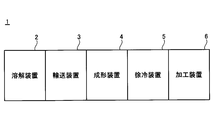
- FIG. 1 is a diagram showing a glass article manufacturing apparatus according to an embodiment.
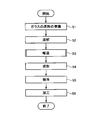
- FIG. 2 is a flowchart of a method for manufacturing a glass article according to an embodiment.
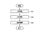
- FIG. 3 is a flowchart of an example of S3 in FIG.
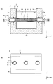
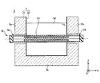
- FIG. 4 (A) is a cross-sectional view of the molten glass transport device according to the embodiment, and
- FIG. 4 (B) is a side view of the transport device shown in FIG. 4 (A).
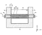
- FIG. 5 is a cross-sectional view of the transport device according to the first modification.
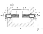
- FIG. 6 is a cross-sectional view of the transport device according to the second modification.
- FIG. 7 is a cross-sectional view of the transport device according to the third modification.
- FIG. 8 (A) is a cross-sectional view of the transport device according to the fourth modification
- FIG. 8 (B) is a side view of the transport device shown in FIG. 8 (A).
- FIG. 9 is a cross-sectional view of the transport device according to the fifth modification.
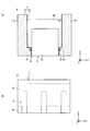
- 10 (A) is a cross-sectional view of the transport device according to the sixth modification
- FIG. 10 (B) is a side view of the transport device shown in FIG. 10 (A).
- 11 (A) is a cross-sectional view of the transport device according to the seventh modification
- FIG. 11 (B) is a side view of the transport device shown in FIG. 11 (A).
- FIG. 12 is a cross-sectional view of the transport device according to the eighth modification.
- the glass article manufacturing apparatus 1 includes a melting apparatus 2, a transport apparatus 3, a molding apparatus 4, a slow cooling apparatus 5, and a processing apparatus 6.
- the melting device 2 melts the raw material of glass to produce molten glass.
- a plurality of types of glass raw materials are prepared and mixed in advance at a mixing ratio according to the composition of the glass.
- the melting device 2 puts the mixed raw material into the melting furnace, melts the mixed raw material inside the melting furnace, and produces molten glass.
- the melting device 2 may be any known furnace, and may be a combustion furnace using a gas burner or a combustion furnace using submerged combustion.
- the composition of the glass is, for example, an oxide-based mol%, a SiO 2 content of 50% or more and 75% or less, and an Al 2 O 3 content of 0% or more and 20%.
- the total content of Li 2 O, Na 2 O and K 2 O is 5% or more and 25% or less
- the total content of MgO, CaO, SrO and BaO is 0% or more and 20% or less.
- the mixed raw materials are, for example, silica sand, dolomite (MgCO 3 CaCO 3 ), limestone (CaCO 3 ), sodium carbonate (Na 2 CO 3 ), aluminum oxide (Al 2 O 3 ) and a clarifying agent.
- the fining agent is sodium sulfate (Na 2 SO 4 ), salt (NaCl), antimony oxide (Sb 2 O 5 ), tin oxide (SnO 2 ) and the like.
- the glass is not limited to soda lime glass, and may be, for example, non-alkali borosilicate glass or aluminosilicate glass.
- the mixed raw material may or may not be granulated before being put into the melting furnace.
- the melting device 2 may put the mixed raw material and the glass cullet into the melting furnace.
- the glass cullet may be mixed with the mixing raw material before being charged into the melting furnace, or may be charged into the melting furnace separately from the mixed raw material.
- the transport device 3 transports the molten glass produced by the melting device 2.
- the molten glass flows from the melting device 2 toward the molding device 4. In the molten glass, the main flow does not flow back, but flows in a desired direction.
- the transport device 3 transports the molten glass, and performs primary clarification, secondary clarification, and temperature adjustment of the molten glass.
- the transport device 3 may be a clarification tank. However, there may be backflow due to local convection that is not the main flow in the transportation process.
- the temperature of the molten glass is raised above the melting temperature, the bubble diameter is increased, and the bubbles float on the liquid surface.
- bubbles expand as the temperature rises.
- gas is generated by the reduction reaction of the fining agent contained in the molten glass, the generated gas is absorbed by the bubbles, and the bubbles grow.
- the temperature of the molten glass is lowered below the primary clarification temperature, and the remaining bubbles are shrunk.
- the bubbles shrink due to the temperature drop.
- the temperature is lowered contrary to the primary clarification, so that the reaction opposite to the primary clarification occurs. Therefore, the gas in the bubbles is reabsorbed by the molten glass, and the bubbles shrink.
- the temperature of the molten glass is adjusted to the molding temperature.
- the temperature adjustment not only the temperature of the molten glass is adjusted to the molding temperature, but also the temperature of the molten glass may be made uniform by stirring the molten glass or the like. Molding unevenness due to temperature unevenness of molten glass can be suppressed.
- the secondary clarification may be included in the temperature adjustment.
- the raw material for glass does not have to contain a fining agent.
- defoaming under reduced pressure may be used regardless of the presence or absence of a fining agent.
- bubbles in the molten glass are defoamed in a reduced pressure atmosphere. Details of the transport device 3 will be described later.
- the molding device 4 molds the molten glass transported by the transport device 3 into a glass having a desired shape.
- a float method, a fusion method, a rollout method, or the like is used as a molding method for obtaining plate-shaped glass.
- the slow cooling device 5 slowly cools the glass molded by the molding device 4.
- the slow cooling device 5 has, for example, a slow cooling furnace and a transfer roller that conveys the glass in a desired direction inside the slow cooling furnace. A plurality of transfer rollers are arranged at intervals in the horizontal direction, for example.
- the glass is slowly cooled while being transported from the inlet to the outlet of the slow cooling furnace. By slowly cooling the glass, a glass with less residual strain can be obtained.
- the processing device 6 processes the glass slowly cooled by the slow cooling device 5 into a glass article.
- the processing device 6 may be one or more selected from, for example, a cutting device, a grinding device, a polishing device, and a coating device.
- the cutting device cuts out a glass article from the glass slowly cooled by the slow cooling device 5.
- the cutting device forms, for example, a scribe line on the glass slowly cooled by the slow cooling device 5, and cuts the glass along the scribe line.
- the method for producing a glass article includes S1 to S6.
- a raw material for glass is prepared.
- the melting device 2 melts the raw material to produce molten glass.
- the transport device 3 transports the molten glass produced by the melting device 2.
- S3 includes S31 to S33 as shown in FIG.
- the transport device 3 carries out the primary clarification of the molten glass.
- the transport device 3 carries out secondary clarification of the molten glass.
- the transport device 3 adjusts the temperature of the molten glass.
- the secondary clarification may be included in the temperature adjustment.
- the inside of the transport device 3 may be depressurized and the defoaming method may be carried out.
- the molding device 4 forms the molten glass transported by the transport device 3 into a glass having a desired shape.
- the slow cooling device 5 slowly cools the glass molded by the molding device 4.
- the processing device 6 processes the glass slowly cooled by the slow cooling device 5 into a glass article.
- the transport device 3 transports the molten glass produced by the melting device 2.
- the molten glass flows from the melting device 2 toward the molding device 4.
- the transport device 3 includes one or more selected from horizontal channels, vertical channels, and diagonal channels.
- the direction of flow in the vertical flow path may be upward or downward.
- the direction of the flow in the diagonal flow path may be diagonally upward or diagonally downward.
- the cross-sectional shape of the flow path orthogonal to the flow may be circular, elliptical, or rectangular, and may change in the middle.
- the size of the cross section orthogonal to the flow may be constant or may change in the middle.
- the main flow does not flow back, but flows in a desired direction.
- the transport device 3 transports the molten glass and carries out primary clarification, secondary clarification, temperature adjustment, etc. of the molten glass.
- the primary clarification, secondary clarification, and temperature adjustment may be carried out in a flow path having a circular or elliptical cross-sectional shape orthogonal to the flow, or may be carried out in a rectangular flow path.
- a space for exhaust is formed above the liquid surface.
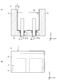
- the transport device 3 includes a wall 7 in contact with the molten glass M.
- the X-axis direction, the Y-axis direction, and the Z-axis direction are directions orthogonal to each other, the X-axis direction and the Y-axis direction are horizontal directions, and the Z-axis direction is a vertical direction.
- the flow direction of the molten glass M is the X-axis direction.
- the wall 7 includes, for example, a pair of side walls 7a and 7a that are formed in a gutter shape and face each other in the Y-axis direction, and a lower wall 7b that connects the lower ends of the pair of side walls 7a and 7a.
- the upper part of the gutter-shaped wall 7 is covered with a ceiling (not shown).
- the wall 7 has a refractory 71 such as a brick.
- the wall 7 has a metal layer 72 in order to prevent the components of the refractory 71 from eluting into the molten glass M.
- the metal layer 72 is a lining arranged inside the refractory 71, and is in contact with the molten glass M to guide the molten glass M in a desired direction.
- the metal layer 72 may be formed of, for example, a metal containing at least one selected from platinum (Pt), rhodium (Rh), tungsten (W), iridium (Ir) and molybdenum (Mo).
- Metals include alloys.
- the alloy may have a total content of Pt, Rh, W, Ir, and Mo of 80% by mass or more and 100% by mass or less.
- Pt, Rh, W, Ir and Mo have excellent corrosion resistance to molten glass.
- the wall 7 since a part of the wall 7 (for example, the upper end portion) does not come into contact with the molten glass M, it may be a refractory 71 that is not covered with the metal layer 72.
- the metal layer 72 may be a layer formed by thermal spraying of a metal inside the refractory material 71.
- the metal layer 72 is, for example, gutter-shaped and opens upward. When a space is formed on the liquid surface of the molten glass M, the ceiling (not shown) does not come into contact with the molten glass M, so that the ceiling does not have to include the metal layer 72. As will be described later, the metal layer 72 has a pipe shape and may be closed with a cross section orthogonal to the flow direction of the molten glass M.
- the metal layer 72 does not need to be energized and heated. Further, the wall 7 does not need to be heated from the outside. Therefore, the metal layer 72 has a high degree of freedom in design.
- the transport device 3 includes a heater 8 in order to adjust the temperature of the molten glass M.
- the heater 8 includes a metal cover 81 and a heat generating member 82.
- the metal cover 81 projects inside the wall 7 and comes into contact with the molten glass M.
- the heat generating member 82 is electrically insulated from the metal cover 81, emits heat rays by feeding power, and heats the metal cover 81 from the inside.
- the heat generating member 82 is arranged inside the metal cover 81, and heats the molten glass M via the metal cover 81.
- the molten glass M is heated by the heater 8 protruding inside the wall 7.
- the metal layer 72 of the wall 7 does not generate heat, and no current flows through the metal layer 72. Therefore, even if a defect such as a hole occurs in the metal layer 72, the heating performance of the molten glass M is maintained, unlike the techniques of Patent Documents 1 to 5.
- the molten glass M is heated inside the wall 7.
- the thickness of the refractory 71 can be increased without heating the wall 7 from the outside of the wall 7. Therefore, unlike the techniques of Patent Documents 6 to 7, even if a defect such as a hole occurs in the metal layer 72, the refractory 71 is thick, so that the refractory 71 can suppress the leakage of the molten glass M.
- the size of the cross section of the molten glass M can be increased as compared with the techniques of Patent Documents 1 to 7, and the molten glass M can be melted.
- the flow rate of the glass M can be increased.
- the cross section is a cross section orthogonal to the flow.
- the heat generating member 82 is arranged inside the metal cover 81 that is electrically insulated from the heat generating member 82, it is also electrically insulated from the molten glass M. Therefore, unlike the technique of Patent Document 8, it is possible to suppress electric leakage to the molten glass M, suppress the electrochemical reaction of the molten glass M, and suppress the generation of bubbles and the like which are the causes of defects.
- the heater 8 is arranged at a position where it is immersed in the molten glass M.
- the heater 8 is arranged below the liquid level of the molten glass M and above the lower wall 7b. Since the entire circumferential direction of the heater 8 is in contact with the molten glass M, the heat transfer efficiency is good.
- a plurality of heaters 8 may be arranged at intervals in the vertical direction. At least one heater 8 may be arranged below the liquid level of the molten glass M and above the lower wall 7b. The remaining heaters 8 may be arranged so that only the upper portion is exposed from the liquid surface, or all of the remaining heaters 8 may be arranged above the liquid surface.
- the heater 8 has a rod shape, and its longitudinal direction is orthogonal to the inner wall surface 73 of the wall 7.
- the desired portion of the molten glass M can be heated at the shortest distance from the inner wall surface 73 of the wall 7. Therefore, since the length of the heater 8 can be shortened, the rigidity of the heater 8 can be improved and the thermal deformation of the heater 8 can be suppressed.
- the heater 8 is inserted into both the through holes 74 and 74 of the pair of side walls 7a and 7a, for example.
- the entire Y-axis direction of the molten glass M can be heated, and the center of the molten glass M in the Y-axis direction can also be heated.
- the size of the cross section of the molten glass M can be increased, and the flow rate of the molten glass M can be increased.
- the heat generating member 82 extends from the middle of one through hole 74 to the middle of the other through hole 74, for example.
- the entire Y-axis direction of the molten glass M can be heated, and the molten glass M can be cooled and solidified in the middle of the through hole 74.
- the diameter of the through hole 74 is the diameter of the heater 8 so that the heater 8 and the wall 7 do not interfere with each other due to the difference in thermal expansion between the heater 8 and the wall 7 in the process of raising the temperature from room temperature to the operating temperature when the transport device 3 is started up. Is set larger than the diameter of. Therefore, the molten glass M flows into the through hole 74.
- the wall 7 may further have a metal pipe 75 surrounding the through hole 74.
- the metal pipe 75 extends outward from the inner wall surface 73 of the wall 7, and is integrated with the metal layer 72 by welding or the like. Inside the through hole 74, it is possible to prevent the components of the refractory 71 from eluting into the molten glass M.
- the metal pipe 75 may be formed of a metal containing at least one selected from Pt, Rh, W, Ir and Mo, similarly to the metal layer 72.
- Metals include alloys.
- the alloy may have a total content of Pt, Rh, W, Ir, and Mo of 80% by mass or more and 100% by mass or less.
- the metal pipe 75 Since a part of the metal pipe 75 does not come into contact with the molten glass M, it may be formed of a metal other than Pt, Rh, W, Ir and Mo, and is formed of, for example, stainless steel or a nickel alloy. You may. As described above, the metal pipe 75 may be formed by joining a plurality of metals.
- the transport device 3 may have a cooling member 76 for cooling the molten glass M in the through hole 74.
- the cooling member 76 is embedded inside the wall 7, for example, and cools the through hole 74 with a refrigerant or the like.
- a refrigerant a liquid such as water or a gas such as air is used.
- the cooling member 76 is embedded inside the wall 7 in FIG. 4A, the through hole 74 may be cooled from the outside of the wall 7.
- the heater 8 includes the metal cover 81 and the heat generating member 82. Since the metal cover 81 is in contact with the molten glass M, it may be formed of a metal containing one or more selected from Pt, Rh, W, Ir and Mo, similarly to the metal layer 72. Metals include alloys. The alloy may have a total content of Pt, Rh, W, Ir, and Mo of 80% by mass or more and 100% by mass or less.
- the metal cover 81 since a part of the metal cover 81 (for example, the end portion in the longitudinal direction) does not come into contact with the molten glass M, it may be formed of a metal other than Pt, Rh, W, Ir and Mo, for example, stainless steel. Alternatively, it may be formed of a nickel alloy or the like. In this way, the metal cover 81 may be formed by joining a plurality of metals.
- the metal cover 81 is formed in the shape of a pipe, for example, and houses the heat generating member 82 inside.
- the thickness of the metal cover 81 may be thicker than the thickness of the metal layer 72. It is possible to prevent defects such as holes from occurring in the metal cover 81, and it is possible to prevent the molten glass M from flowing into the inside of the metal cover 81. Even if a defect such as a hole occurs in the metal layer 72, there is no problem. This is because the refractory 71 prevents the molten glass M from leaking.
- the heat generating member 82 may be made of a metal containing at least one selected from, for example, Mo, W, Ta, Nb, Ir, Pt, and Rh. Metals include alloys. Since these metals have high electrical conductivity, they may be formed in a coil shape in order to increase the electrical resistance.
- the heat generating member 82 may be formed of molybdenum dissilicate (MoSi 2 ), silicon carbide (SiC), lanthanum chromite (LaCrO 3), or the like. Since these materials have a higher electrical resistivity than metal, they do not have to be formed in a coil shape, and may be formed in a rod shape or a pipe shape, for example.
- MoSi 2 molybdenum dissilicate
- SiC silicon carbide
- LaCrO 3 lanthanum chromite
- the heat generating member 82 may be formed of a material containing carbon (C) as a main component, such as graphite or a carbon fiber reinforced carbon composite material (Carbon Fiber Reinforced Carbon Composite: CC composite). Since the material containing C as a main component has high electrical conductivity, the heat generating member 82 may have a plate shape or a pipe shape having slits arranged periodically in order to increase the electrical resistance. For example, the slits may be periodically arranged in the longitudinal direction of the plate which is the heat generating member 82, or the slits may be periodically arranged in the circumferential direction of the pipe which is the heat generating member 82.
- C carbon
- CC composite Carbon Fiber Reinforced Carbon Composite
- the heater 8 may further include a spacer 83.
- the spacer 83 electrically insulates between the metal cover 81 and the heat generating member 82.
- the spacer 83 is formed in a pipe shape, for example, and is inserted into the pipe-shaped metal cover 81.
- the length of the spacer 83 is equal to or longer than the length of the heat generating member 82, and the heat generating member 82 is arranged inside the spacer 83.
- the spacer 83 prevents the heat generating member 82 from coming into contact with the metal cover 81, so that the heat generating member 82 and the metal cover 81 can be electrically insulated.
- the length of the spacer 83 may be shorter than the length of the heat generating member 82, and a plurality of ring-shaped spacers 83 may be arranged at intervals in the longitudinal direction of the metal cover 81.
- the spacer 83 has a transmittance of 50% or more with respect to the heat rays radiated from the heat generating member 82.
- the wavelength of the heat ray is, for example, 400 nm to 5 ⁇ m.
- the heat rays pass through the spacer 83 and irradiate the metal cover 81 to heat the metal cover 81 from the inside.
- the spacer 83 is formed of, for example, sapphire (single crystal aluminum oxide), transparent polycrystalline aluminum oxide, aluminum nitride, yttrium oxide, spinel, zirconium oxide, yttrium aluminum garnet, magnesium oxide, or quartz. Sapphire is preferable as the spacer 83 from the viewpoint of heat ray transmittance and heat resistance.
- the specific elastic modulus of the heat generating member 82 (the value obtained by dividing the elastic modulus by the specific gravity) is high and the heat generating member 82 hardly bends, the spacer 83 is unnecessary.
- the material of the heat generating member 82 having a high specific elastic modulus include materials containing MoSi 2 , SiC, LaCrO 3 , and C as main components.
- the heater 8 may further include a lid 84.
- the lid 84 seals the internal space of the metal cover 81.
- the lids 84 are provided at both ends of the metal cover 81 in the longitudinal direction, for example.
- the internal space of the metal cover 81 can be filled with an inert gas or a reducing gas.
- the inert gas for example, nitrogen gas or argon gas is used.
- the reducing gas for example, a hydrogen-containing gas is used.
- Oxidation of the heat generating member 82 can be prevented, and a material that cannot be used in the atmospheric atmosphere can be used as the material of the heat generating member 82.
- a material that cannot be used in the atmospheric atmosphere include materials containing Mo, W, Ta, Nb, Ir, and carbon as main components.
- Examples of the material of the heat generating member 82 that can be used in the atmospheric atmosphere include Pt, Rh, MoSi 2 , SiC, and LaCrO 3 .
- the lid 84 is unnecessary.
- the heater 8 may further include a lead wire 85.
- the lead wire 85 is electrically insulated from the metal cover 81 and generates a voltage at both ends of the heat generating member 82.
- the lead wire 85 has a lower resistance than the heat generating member 82 and hardly generates heat.
- a plurality of heaters 8 may be arranged in a row at intervals in the X-axis direction.
- the X-axis direction is the flow direction of the molten glass M.
- a plurality of heaters 8 may be arranged in a matrix in the X-axis direction and the Z-axis direction. Further, a plurality of heaters 8 may be staggered in the X-axis direction in the Y-axis direction.
- the opening edge of the through hole 74 of the metal layer 72 may be integrated with the pipe-shaped metal cover 81 by welding or the like over the entire circumferential direction. Since the molten glass M does not flow into the through hole 74, the dimensional accuracy of the through hole 74 can be relaxed. Further, the cooling member 76 shown in FIG. 4A is unnecessary.
- a plurality of heaters 8 may be arranged in a row at intervals in the X-axis direction.
- a plurality of heaters 8 may be arranged in a matrix in the X-axis direction and the Z-axis direction. Further, a plurality of heaters 8 may be staggered in the X-axis direction in the Y-axis direction.
- the metal cover 81 of the heater 8 may be a double pipe, or may have an inner cylinder 81a and an outer cylinder 81b.
- the inner cylinder 81a is inserted into the through hole 74 of the side wall 7a.
- the outer cylinder 81b is bridged between the pair of side walls 7a and 7a without being inserted into the through hole 74 of the side wall 7a.
- the opening edge of the through hole 74 of the metal layer 72 is integrated with the pipe-shaped outer cylinder 81b by welding or the like over the entire circumferential direction. Since the molten glass M does not flow into the through hole 74, the dimensional accuracy of the through hole 74 can be relaxed. Further, the cooling member 76 shown in FIG. 4A is unnecessary.
- the outer cylinder 81b protrudes inside the wall 7 and comes into contact with the molten glass M.
- the thickness of the outer cylinder 81b may be thicker than the thickness of the metal layer 72. It is possible to prevent defects such as holes from occurring in the outer cylinder 81b, and prevent the molten glass M from flowing into the through hole 74. Even if a defect such as a hole occurs in the metal layer 72, there is no problem. This is because the refractory 71 prevents the molten glass M from leaking.
- the metal cover 81 does not have to have the inner cylinder 81a, and may have only the outer cylinder 81b. That is, the metal cover 81 may be a single tube.
- a plurality of heaters 8 may be arranged in a row at intervals in the X-axis direction.
- a plurality of heaters 8 may be arranged in a matrix in the X-axis direction and the Z-axis direction. Further, a plurality of heaters 8 may be staggered in the X-axis direction in the Y-axis direction.
- the tip of the pipe-shaped metal cover 81 is closed so that the molten glass M does not flow into the metal cover 81. Therefore, the pair of lead wires 85 are taken out from the end of the metal cover 81. For example, one lead wire 85 passes through the center of the coiled heat generating member 82 and is taken out from the end of the heater 8 together with the remaining lead wires 85.
- the opening edge of the through hole 74 of the metal layer 72 may be integrated with the pipe-shaped metal cover 81 by welding or the like over the entire circumferential direction. Since the molten glass M does not flow into the through hole 74, the dimensional accuracy of the through hole 74 can be relaxed. Further, the cooling member 76 shown in FIG. 7 is unnecessary.
- the metal cover 81 may have an inner cylinder 81a and an outer cylinder 81b as in the second modification.
- the outer cylinder 81b protrudes inward from the side wall 7a without being inserted into the through hole 74 of the side wall 7a.
- the opening edge of the through hole 74 of the metal layer 72 is integrated with the pipe-shaped outer cylinder 81b by welding or the like over the entire circumferential direction.
- the metal cover 81 does not have to have the inner cylinder 81a, and may have only the outer cylinder 81b. That is, the metal cover 81 may be a single tube.
- a plurality of heaters 8 may be arranged in a row at intervals in the X-axis direction.
- a plurality of heaters 8 may be arranged in a matrix in the X-axis direction and the Z-axis direction. Further, a plurality of heaters 8 may be staggered in the X-axis direction in the Y-axis direction.
- the heater 8 may be inserted through the through hole 74 of the lower wall 7b and project inward (upper side) from the lower wall 7b.
- the heater 8 has, for example, a rod shape, and its longitudinal direction is orthogonal to the inner wall surface (upper surface) of the lower wall 7b. It is possible to prevent bending due to gravity.
- the molten glass M Since the upper end of the pipe-shaped metal cover 81 is arranged below the liquid level of the molten glass M, the molten glass M is closed so as not to flow into the internal space of the metal cover 81. Therefore, the pair of lead wires 85 are taken out from the lower end of the metal cover 81.
- the upper end of the heater 8 is arranged below the liquid level of the molten glass M in this modification, it may be arranged above. In this case, one lead wire 85 may be taken out from the lower end of the heater 8 and the remaining lead wire 85 may be taken out from the upper end of the heater 8.
- the wall 7 may further have a metal pipe 75 surrounding the through hole 74.
- the metal pipe 75 extends from the inner wall surface of the wall 7 to the outside (lower side), and is integrated with the metal layer 72 by welding or the like. Inside the through hole 74, it is possible to prevent the components of the refractory 71 from eluting into the molten glass M.
- the transport device 3 may have a cooling member 76 for cooling the molten glass M in the through hole 74.
- the cooling member 76 is embedded inside the wall 7, for example, and cools the through hole 74 with a refrigerant or the like. Although the cooling member 76 is embedded inside the wall 7 in FIG. 8A, the through hole 74 may be cooled from the outside (lower side) of the wall 7.
- the opening edge of the through hole 74 of the metal layer 72 may be integrated with the pipe-shaped metal cover 81 by welding or the like over the entire circumferential direction. Since the molten glass M does not flow into the through hole 74, the dimensional accuracy of the through hole 74 can be relaxed. Further, the cooling member 76 shown in FIG. 8A is unnecessary.
- the metal cover 81 may have an inner cylinder 81a and an outer cylinder 81b as in the second modification.
- the outer cylinder 81b protrudes inward (upper side) from the lower wall 7b without being inserted into the through hole 74 of the lower wall 7b.
- the opening edge of the through hole 74 of the metal layer 72 is integrated with the pipe-shaped outer cylinder 81b by welding or the like over the entire circumferential direction.
- the metal cover 81 does not have to have the inner cylinder 81a, and may have only the outer cylinder 81b. That is, the metal cover 81 may be a single tube.
- a plurality of heaters 8 may be arranged in a row at intervals in the X-axis direction.
- the plurality of heaters 8 may be arranged in a matrix in the X-axis direction and the Y-axis direction. Further, a plurality of heaters 8 may be staggered in the X-axis direction in the Z-axis direction.
- the heater 8 is inserted through a through hole in a ceiling (not shown) and projects downward from the liquid surface of the molten glass M.
- the heater 8 has, for example, a rod shape, and its longitudinal direction is orthogonal to the lower surface of the ceiling (not shown).
- the through hole of the ceiling does not allow the molten glass M to enter. Therefore, even if the heater 8 is replaced or rearranged with the molten glass M filled in the flow path, the molten glass does not leak.
- the molten glass M Since the lower end of the pipe-shaped metal cover 81 is located below the liquid level of the molten glass M and above the lower wall 7b, the molten glass M is prevented from flowing into the internal space of the metal cover 81. , Closed. Therefore, the pair of lead wires 85 are taken out from the upper end of the metal cover 81.
- the lower end of the pipe-shaped metal cover 81 is arranged above the lower wall 7b, but the technique of the present disclosure is not limited to this.
- a through hole may be formed in the lower wall 7b, and the heater 8 may be inserted through the through hole.
- the lower wall 7b has no through hole.
- a plurality of heaters 8 may be arranged in a row at intervals in the X-axis direction.
- the plurality of heaters 8 may be arranged in a matrix in the X-axis direction and the Y-axis direction. Further, a plurality of heaters 8 may be staggered in the X-axis direction in the Z-axis direction.
- the heater 8 may have a plate-like outer shape orthogonal to the flow of the molten glass M.
- the heater 8 is inserted through the through hole 74 of the lower wall 7b and projects inward (upper side) from the lower wall 7b.
- the upper end of the heater 8 is arranged below the liquid level of the molten glass M. If the heater 8 has a plate shape orthogonal to the flow of the molten glass M, the air bubbles existing in the lower layer of the molten glass M can be forcibly floated toward the liquid surface of the molten glass M by the heater 8.
- the heater 8 may be inserted through a through hole in the ceiling and protrude downward from the liquid level of the molten glass M.
- the lower end of the heater 8 may be arranged above the lower wall 7b.
- the through hole in the ceiling does not allow the molten glass M to enter. Therefore, even if the heater 8 is replaced or rearranged with the molten glass M filled in the flow path, the molten glass does not leak.
- the metal cover 81 may be a pipe having a quadrangular cross section with a closed upper end.
- a heat generating member (not shown) is arranged inside the metal cover 81.
- the heat generating members are formed in, for example, a coil shape, a rod shape, or a tube shape, are arranged vertically, and a plurality of heat generating members are arranged at intervals in the Y-axis direction.
- the heat generating member may be formed in a plate shape.
- the plate which is a heat generating member, may have slits that are periodically arranged in order to increase the electric resistance.
- the first slit and the second slit may be formed alternately at intervals in the Y-axis direction. The first slit extends downward from the upper side of the plate, and the second slit extends upward from the lower side of the plate.
- the opening edge of the through hole 74 of the metal layer 72 is integrated with the box-shaped metal cover 81 opened downward in the entire circumferential direction by welding or the like. May be good. Since the molten glass M does not flow into the through hole 74, the dimensional accuracy of the through hole 74 can be relaxed. Further, the cooling member 76 shown in FIG. 10A is unnecessary.
- the metal cover 81 may have an inner cylinder 81a and an outer cylinder 81b as in the second modification.
- the outer cylinder 81b protrudes inward (upper side) from the lower wall 7b without being inserted into the through hole 74 of the lower wall 7b.
- the opening edge of the through hole 74 of the metal layer 72 is integrated with the pipe-shaped outer cylinder 81b by welding or the like over the entire circumferential direction.
- the metal cover 81 does not have to have the inner cylinder 81a, and may have only the outer cylinder 81b. That is, the metal cover 81 may be a single tube.
- a plurality of heaters 8 may be arranged in a row at intervals in the X-axis direction.
- the plurality of heaters 8 may be arranged in a matrix in the X-axis direction and the Y-axis direction. Further, a plurality of heaters 8 may be staggered in the X-axis direction in the Z-axis direction.
- the heater 8 may have a plate-like outer shape parallel to the flow of the molten glass M.
- the heater 8 is inserted through the through hole 74 of the lower wall 7b and projects inward (upper side) from the lower wall 7b.
- the upper end of the heater 8 is arranged below the liquid level of the molten glass M.
- the bubbles existing in the lower layer of the molten glass M can be forcibly floated toward the liquid surface of the molten glass M.
- the heater 8 may be inserted through a through hole in the ceiling and protrude downward from the liquid level of the molten glass M.
- the lower end of the heater 8 may be arranged above the lower wall 7b.
- the through hole in the ceiling does not allow the molten glass M to enter. Therefore, even if the heater 8 is replaced or rearranged with the molten glass M filled in the flow path, the molten glass does not leak.
- the metal cover 81 may be a pipe having a quadrangular cross section with a closed upper end.
- a heat generating member (not shown) is arranged inside the metal cover 81.
- the heat generating members are formed in, for example, a coil shape, a rod shape, or a tube shape, are arranged vertically, and a plurality of heat generating members are arranged at intervals in the X-axis direction.
- the heat generating member may be formed in a plate shape.
- the plate which is a heat generating member, may have slits that are periodically arranged in order to increase the electric resistance.
- the first slit and the second slit may be formed alternately at intervals in the X-axis direction. The first slit extends downward from the upper side of the plate, and the second slit extends upward from the lower side of the plate.
- the opening edge of the through hole 74 of the metal layer 72 is integrated with the box-shaped metal cover 81 opened downward in the entire circumferential direction by welding or the like. May be good. Since the molten glass M does not flow into the through hole 74, the dimensional accuracy of the through hole 74 can be relaxed. Further, the cooling member 76 shown in FIG. 11A is unnecessary.
- the metal cover 81 may have an inner cylinder 81a and an outer cylinder 81b as in the second modification.
- the outer cylinder 81b protrudes inward (upper side) from the lower wall 7b without being inserted into the through hole 74 of the lower wall 7b.
- the opening edge of the through hole 74 of the metal layer 72 is integrated with the pipe-shaped outer cylinder 81b by welding or the like over the entire circumferential direction.
- the metal cover 81 does not have to have the inner cylinder 81a, and may have only the outer cylinder 81b. That is, the metal cover 81 may be a single tube.
- a plurality of heaters 8 may be arranged in a matrix in the X-axis direction and the Y-axis direction.
- the plurality of heaters 8 may be staggered in the X-axis direction in the Z-axis direction. Further, a plurality of heaters 8 may be arranged in a row at intervals in the X-axis direction.
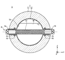
- the wall 7 may be formed in a pipe shape, and the metal layer 72 may also be formed in a pipe shape.
- the metal layer 72 is closed with a cross section orthogonal to the flow direction of the molten glass M. It is possible to suppress the erosion of the refractory 71 by the steam of the molten glass M, and to prevent the components of the refractory 71 from falling onto the molten glass M and being mixed.
- the metal layer 72 is a pipe having a circular cross section in FIG. 12, it may be a pipe having a rectangular cross section.
- the heater 8 has, for example, a rod shape, and its longitudinal direction is orthogonal to the inner wall surface 73 of the wall 7.
- the heater 8 is inserted through both the pair of through holes 74, 74 of the wall 7.
- the heat generating member 82 extends from the middle of one through hole 74 to the middle of the other through hole 74.
- separate heaters 8 may be inserted through the through hole 74 on one side and the through hole 74 on the other side. Since the length of the heater 8 can be shortened, the rigidity of the heater 8 can be improved and the thermal deformation of the heater 8 can be suppressed.
- the wall 7 may further have a metal pipe 75 surrounding the through hole 74.
- the metal pipe 75 extends outward from the inner wall surface 73 of the wall 7, and is integrated with the metal layer 72 by welding or the like. Inside the through hole 74, it is possible to prevent the components of the refractory 71 from eluting into the molten glass M.
- the transport device 3 may have a cooling member 76 for cooling the molten glass M in the through hole 74.
- the cooling member 76 is embedded inside the wall 7, for example, and cools the through hole 74 with a refrigerant or the like. Although the cooling member 76 is embedded inside the wall 7 in FIG. 12, the through hole 74 may be cooled from the outside of the wall 7.
- the opening edge of the through hole 74 of the metal layer 72 may be integrated with the pipe-shaped metal cover 81 by welding or the like over the entire circumferential direction. Since the molten glass M does not flow into the through hole 74, the dimensional accuracy of the through hole 74 can be relaxed. Further, the cooling member 76 shown in FIG. 12 is unnecessary.
- the metal cover 81 may have an inner cylinder 81a and an outer cylinder 81b as in the second modification.
- the outer cylinder 81b protrudes inward from the wall 7 without being inserted into the through hole 74 of the wall 7.
- the opening edge of the through hole 74 of the metal layer 72 is integrated with the pipe-shaped outer cylinder 81b by welding or the like over the entire circumferential direction.
- the metal cover 81 does not have to have the inner cylinder 81a, and may have only the outer cylinder 81b. That is, the metal cover 81 may be a single tube.
- a plurality of heaters 8 may be arranged in a row at intervals in the X-axis direction. Further, a plurality of heaters 8 may be arranged at intervals in the circumferential direction of the pipe-shaped wall 7. A plurality of heaters 8 may be spirally arranged on a pipe-shaped wall 7.
- the present disclosure is not limited to the above-described embodiment and the like.
- various changes, modifications, replacements, additions, deletions, and combinations are possible. Of course, they also belong to the technical scope of the present disclosure.
Landscapes
- Chemical & Material Sciences (AREA)
- Engineering & Computer Science (AREA)
- Materials Engineering (AREA)
- Organic Chemistry (AREA)
- Mechanical Engineering (AREA)
- General Engineering & Computer Science (AREA)
- Physics & Mathematics (AREA)
- Thermal Sciences (AREA)
- Glass Melting And Manufacturing (AREA)
Priority Applications (4)
| Application Number | Priority Date | Filing Date | Title |
|---|---|---|---|
| EP20899444.2A EP4074664A4 (en) | 2019-12-10 | 2020-12-04 | Melted glass transport device, glass article manufacturing device, and glass article manufacturing method |
| JP2021563912A JPWO2021117618A1 (enExample) | 2019-12-10 | 2020-12-04 | |
| CN202080084961.9A CN114787089A (zh) | 2019-12-10 | 2020-12-04 | 熔融玻璃的输送装置、玻璃物品的制造装置以及玻璃物品的制造方法 |
| US17/805,309 US20220298048A1 (en) | 2019-12-10 | 2022-06-03 | Apparatus for transferring molten glass, apparatus for producing glass article, and method for producing glass article |
Applications Claiming Priority (2)
| Application Number | Priority Date | Filing Date | Title |
|---|---|---|---|
| JP2019223194 | 2019-12-10 | ||
| JP2019-223194 | 2019-12-10 |
Related Child Applications (1)
| Application Number | Title | Priority Date | Filing Date |
|---|---|---|---|
| US17/805,309 Continuation US20220298048A1 (en) | 2019-12-10 | 2022-06-03 | Apparatus for transferring molten glass, apparatus for producing glass article, and method for producing glass article |
Publications (1)
| Publication Number | Publication Date |
|---|---|
| WO2021117618A1 true WO2021117618A1 (ja) | 2021-06-17 |
Family
ID=76330323
Family Applications (1)
| Application Number | Title | Priority Date | Filing Date |
|---|---|---|---|
| PCT/JP2020/045184 Ceased WO2021117618A1 (ja) | 2019-12-10 | 2020-12-04 | 溶融ガラスの輸送装置、ガラス物品の製造装置、及びガラス物品の製造方法 |
Country Status (5)
| Country | Link |
|---|---|
| US (1) | US20220298048A1 (enExample) |
| EP (1) | EP4074664A4 (enExample) |
| JP (1) | JPWO2021117618A1 (enExample) |
| CN (1) | CN114787089A (enExample) |
| WO (1) | WO2021117618A1 (enExample) |
Cited By (1)
| Publication number | Priority date | Publication date | Assignee | Title |
|---|---|---|---|---|
| US12378147B2 (en) | 2019-05-08 | 2025-08-05 | AGC Inc. | Method of producing melt, method of producing glass article, melting apparatus, and equipment for producing glass article |
Families Citing this family (1)
| Publication number | Priority date | Publication date | Assignee | Title |
|---|---|---|---|---|
| JP6958105B2 (ja) * | 2017-08-18 | 2021-11-02 | 日本電気硝子株式会社 | ガラス物品の製造方法及び溶融炉 |
Citations (11)
| Publication number | Priority date | Publication date | Assignee | Title |
|---|---|---|---|---|
| US3912477A (en) | 1973-01-05 | 1975-10-14 | Owens Corning Fiberglass Corp | Apparatus for processing glass batch material |
| JPS5415764B2 (enExample) | 1975-05-20 | 1979-06-18 | ||
| JPS6049225B2 (ja) | 1977-05-27 | 1985-10-31 | コニカ株式会社 | 螢光増白組成物 |
| JPS6162395U (enExample) * | 1984-09-28 | 1986-04-26 | ||
| JPH0135827B2 (enExample) | 1980-06-06 | 1989-07-27 | Otsuka Pharma Co Ltd | |
| JPH0220375B2 (enExample) | 1983-01-25 | 1990-05-09 | Hitachi Seiki Kk | |
| JPH0233221B2 (ja) | 1982-09-06 | 1990-07-26 | Kawaguchi Electric Works | Kaisenbunriki |
| JP2570350B2 (ja) | 1987-12-24 | 1997-01-08 | 日本板硝子株式会社 | ガラス溶融炉 |
| WO2014192478A1 (ja) * | 2013-05-30 | 2014-12-04 | 日本碍子株式会社 | 赤外線加熱ユニット,赤外線加熱装置及び乾燥装置 |
| JP2017065973A (ja) | 2015-09-30 | 2017-04-06 | AvanStrate株式会社 | ガラス基板の製造方法およびガラス基板の製造装置 |
| WO2019244802A1 (ja) * | 2018-06-22 | 2019-12-26 | Agc株式会社 | ヒータ、ガラス物品の製造装置、およびガラス物品の製造方法 |
Family Cites Families (7)
| Publication number | Priority date | Publication date | Assignee | Title |
|---|---|---|---|---|
| US4896047A (en) * | 1988-04-11 | 1990-01-23 | Westinghouse Electric Corp. | Method and apparatus of periodically obtaining accurate opacity monitor readings of an exhaust gas stream |
| JP2007302507A (ja) * | 2006-05-11 | 2007-11-22 | Japan Steel Works Ltd:The | 超伝導薄膜の製造方法 |
| JP5752648B2 (ja) * | 2012-06-29 | 2015-07-22 | AvanStrate株式会社 | ガラス基板の製造方法及び製造装置 |
| JP5752647B2 (ja) * | 2012-06-29 | 2015-07-22 | AvanStrate株式会社 | ガラス基板の製造方法 |
| JP2015124096A (ja) * | 2013-12-25 | 2015-07-06 | 並木精密宝石株式会社 | 大型基板用の単結晶サファイアリボン |
| US10656024B2 (en) * | 2016-04-05 | 2020-05-19 | Corning Incorporated | Molten material thermocouple methods and apparatus |
| JP7116411B2 (ja) * | 2017-06-29 | 2022-08-10 | 株式会社タムラ製作所 | 単結晶育成装置、抵抗発熱体、及び単結晶育成方法 |
-
2020
- 2020-12-04 JP JP2021563912A patent/JPWO2021117618A1/ja active Pending
- 2020-12-04 EP EP20899444.2A patent/EP4074664A4/en active Pending
- 2020-12-04 WO PCT/JP2020/045184 patent/WO2021117618A1/ja not_active Ceased
- 2020-12-04 CN CN202080084961.9A patent/CN114787089A/zh active Pending
-
2022
- 2022-06-03 US US17/805,309 patent/US20220298048A1/en not_active Abandoned
Patent Citations (11)
| Publication number | Priority date | Publication date | Assignee | Title |
|---|---|---|---|---|
| US3912477A (en) | 1973-01-05 | 1975-10-14 | Owens Corning Fiberglass Corp | Apparatus for processing glass batch material |
| JPS5415764B2 (enExample) | 1975-05-20 | 1979-06-18 | ||
| JPS6049225B2 (ja) | 1977-05-27 | 1985-10-31 | コニカ株式会社 | 螢光増白組成物 |
| JPH0135827B2 (enExample) | 1980-06-06 | 1989-07-27 | Otsuka Pharma Co Ltd | |
| JPH0233221B2 (ja) | 1982-09-06 | 1990-07-26 | Kawaguchi Electric Works | Kaisenbunriki |
| JPH0220375B2 (enExample) | 1983-01-25 | 1990-05-09 | Hitachi Seiki Kk | |
| JPS6162395U (enExample) * | 1984-09-28 | 1986-04-26 | ||
| JP2570350B2 (ja) | 1987-12-24 | 1997-01-08 | 日本板硝子株式会社 | ガラス溶融炉 |
| WO2014192478A1 (ja) * | 2013-05-30 | 2014-12-04 | 日本碍子株式会社 | 赤外線加熱ユニット,赤外線加熱装置及び乾燥装置 |
| JP2017065973A (ja) | 2015-09-30 | 2017-04-06 | AvanStrate株式会社 | ガラス基板の製造方法およびガラス基板の製造装置 |
| WO2019244802A1 (ja) * | 2018-06-22 | 2019-12-26 | Agc株式会社 | ヒータ、ガラス物品の製造装置、およびガラス物品の製造方法 |
Non-Patent Citations (1)
| Title |
|---|
| See also references of EP4074664A4 |
Cited By (1)
| Publication number | Priority date | Publication date | Assignee | Title |
|---|---|---|---|---|
| US12378147B2 (en) | 2019-05-08 | 2025-08-05 | AGC Inc. | Method of producing melt, method of producing glass article, melting apparatus, and equipment for producing glass article |
Also Published As
| Publication number | Publication date |
|---|---|
| EP4074664A4 (en) | 2024-01-03 |
| EP4074664A1 (en) | 2022-10-19 |
| CN114787089A (zh) | 2022-07-22 |
| US20220298048A1 (en) | 2022-09-22 |
| JPWO2021117618A1 (enExample) | 2021-06-17 |
Similar Documents
| Publication | Publication Date | Title |
|---|---|---|
| TWI718154B (zh) | 用於處理熔融玻璃的裝置及方法 | |
| KR101300980B1 (ko) | 글래스 기판의 제조 방법 | |
| US20100251772A1 (en) | Molten glass producing apparatus and molten glass producing method employing the apparatus | |
| US20220298048A1 (en) | Apparatus for transferring molten glass, apparatus for producing glass article, and method for producing glass article | |
| TW201840488A (zh) | 用於減少玻璃熔體表面上氣泡壽命之方法 | |
| JP2019510977A (ja) | 溶融材料の熱電対の方法および装置 | |
| US11530152B2 (en) | Method for manufacturing glass article, and melting furnace | |
| JP2017030978A (ja) | フロートガラス製造装置、およびフロートガラス製造方法 | |
| JP5731437B2 (ja) | ガラス板の製造方法 | |
| WO2014091814A1 (ja) | 板ガラスの製造方法、および板ガラスの製造装置 | |
| JP6792825B2 (ja) | ガラス物品の製造方法及び溶融炉 | |
| JP5192100B2 (ja) | ガラス基板の製造方法 | |
| US20250164187A1 (en) | Glass melting furnaces and vessels with improved thermal performance | |
| CN104788010B (zh) | 浮法玻璃制造装置及浮法玻璃制造方法 | |
| CN111977942B (zh) | 熔融玻璃传送装置、玻璃制造装置及玻璃制造方法 | |
| JP6566824B2 (ja) | ガラス基板の製造方法 | |
| JP2017178731A (ja) | ガラス板の製造方法 | |
| KR20230066343A (ko) | 유리 물품의 형성 방법 | |
| KR100790788B1 (ko) | 연속식 유리 용융로 | |
| JP6749123B2 (ja) | ガラス基板の製造方法、及び、ガラス基板の製造装置 | |
| JP6630217B2 (ja) | ガラス板の製造方法 | |
| KR20190078512A (ko) | 유리 기판 제조 장치 및 유리 기판의 제조 방법 | |
| WO2022270555A1 (ja) | ガラス物品の製造装置及び製造方法 | |
| JP2017178707A (ja) | ガラス基板の製造方法、及び、ガラス基板の製造装置 | |
| JP2017178760A (ja) | ガラス板の製造方法及び熔解槽 |
Legal Events
| Date | Code | Title | Description |
|---|---|---|---|
| 121 | Ep: the epo has been informed by wipo that ep was designated in this application |
Ref document number: 20899444 Country of ref document: EP Kind code of ref document: A1 |
|
| ENP | Entry into the national phase |
Ref document number: 2021563912 Country of ref document: JP Kind code of ref document: A |
|
| NENP | Non-entry into the national phase |
Ref country code: DE |
|
| ENP | Entry into the national phase |
Ref document number: 2020899444 Country of ref document: EP Effective date: 20220711 |