WO2021117532A1 - 吸収性物品 - Google Patents
吸収性物品 Download PDFInfo
- Publication number
- WO2021117532A1 WO2021117532A1 PCT/JP2020/044488 JP2020044488W WO2021117532A1 WO 2021117532 A1 WO2021117532 A1 WO 2021117532A1 JP 2020044488 W JP2020044488 W JP 2020044488W WO 2021117532 A1 WO2021117532 A1 WO 2021117532A1
- Authority
- WO
- WIPO (PCT)
- Prior art keywords
- row
- convex portion
- convex
- fixing
- absorbent article
- Prior art date
- Legal status (The legal status is an assumption and is not a legal conclusion. Google has not performed a legal analysis and makes no representation as to the accuracy of the status listed.)
- Ceased
Links
Images
Classifications
-
- A—HUMAN NECESSITIES
- A61—MEDICAL OR VETERINARY SCIENCE; HYGIENE
- A61F—FILTERS IMPLANTABLE INTO BLOOD VESSELS; PROSTHESES; DEVICES PROVIDING PATENCY TO, OR PREVENTING COLLAPSING OF, TUBULAR STRUCTURES OF THE BODY, e.g. STENTS; ORTHOPAEDIC, NURSING OR CONTRACEPTIVE DEVICES; FOMENTATION; TREATMENT OR PROTECTION OF EYES OR EARS; BANDAGES, DRESSINGS OR ABSORBENT PADS; FIRST-AID KITS
- A61F13/00—Bandages or dressings; Absorbent pads
- A61F13/15—Absorbent pads, e.g. sanitary towels, swabs or tampons for external or internal application to the body; Supporting or fastening means therefor; Tampon applicators
- A61F13/51—Absorbent pads, e.g. sanitary towels, swabs or tampons for external or internal application to the body; Supporting or fastening means therefor; Tampon applicators characterised by the outer layers of the pads
- A61F13/511—Topsheet, i.e. the permeable cover or layer facing the skin
Definitions
- the present invention relates to an absorbent article.
- absorbent articles used for absorbing liquid discharged from the body are non-woven fabrics that have been subjected to perforation treatment and non-woven fabrics that have many irregularities as their surface sheets. Etc. are arranged.
- the valley portion and the mountain portion facing the liquid receiving side are formed on the surface sheet in a wavy direction in the width direction extending in the longitudinal direction and orthogonal to the longitudinal direction.
- an absorbent article in which a rough portion having a low density of fibers constituting the surface sheet and a dense portion having a high density are alternately formed in the longitudinal direction is disclosed.
- the present invention has a liquid-permeable front surface sheet, a back surface sheet, and an absorber located between the front surface sheet and the back surface sheet, and has a longitudinal direction corresponding to the front-rear direction of the wearer and a width orthogonal to the longitudinal direction. It is an absorbent article having a direction.
- the surface sheet is located adjacent to the first ridge portion extending along the longitudinal direction and the first ridge portion, and is arranged so as to form a row and periodically meanrate along the longitudinal direction.
- a third convex portion that is arranged at a position symmetrical to the second convex portion row and has a shape symmetrical to the second convex portion row with the ridgeline of the second convex portion row and the first convex portion as the axis of symmetry. With columns.
- the first convex portion, the second convex portion row, the first convex portion row, and the third convex portion row are arranged in this order. Repeating units are formed.
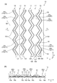
- FIG. 1 (a) is a schematic plan view on the skin-facing surface side showing an embodiment of the surface sheet constituting the absorbent article of the present invention
- FIG. 1 (b) is a plan view of FIG. 1 (a).
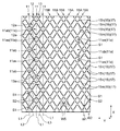
- FIG. 2 is a schematic plan view on the skin-facing surface side showing another embodiment of the surface sheet constituting the absorbent article of the present invention
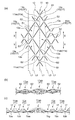
- 3 (a) is an enlarged view of a main part in FIG. 2
- FIG. 3 (b) is a cross-sectional view taken along the line II-II of FIG. 3 (a)
- FIG. 3 (c) is a sectional view taken along the line II-II.
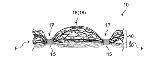
- FIG. 4 is a schematic cross-sectional view of the surface sheet constituting the absorbent article of the present invention in still another embodiment.
- the present invention relates to an absorbent article that can eliminate the drawbacks of the prior art.
- the absorbent article of the present invention generally has a vertically long shape having a longitudinal direction corresponding to a direction extending from the ventral side of the wearer to the dorsal side via the crotch portion and a width direction orthogonal to the longitudinal direction.
- the absorbent article has a crotch portion arranged in the crotch portion of the wearer and a ventral and dorsal portions extending in front of and behind the inseam.
- the inseam has an excretion part facing area including an excretion part facing part which is arranged to face the excretion part such as the wearer's vaginal opening when the absorbent article is worn, and the excretion part facing area usually absorbs. It is located in and near the central part in the longitudinal direction and the central part in the width direction of the sex article.
- the absorbent article generally includes a front surface sheet located on the skin facing surface side of the wearer, a back surface sheet located on the non-skin facing surface side, and an absorbent body interposed between the front surface sheet and the back surface sheet.
- the surface sheet one or more sheets having liquid permeability, such as a non-woven fabric or a perforated film, can be used.
- the surface sheet may have an uneven shape on the side facing the skin. For example, a plurality of convex portions can be formed in a scattered spot shape on the skin-facing surface side of the surface sheet. Alternatively, ridges and grooves extending in one direction can be alternately formed on the skin-facing surface side of the surface sheet.
- a surface sheet can also be formed by using a multi-layer sheet formed by laminating two or more non-woven fabrics in a peelable or non-peelable manner.
- the convex portion or the ridged portion may have a solid structure or a hollow structure.
- the back sheet for example, a liquid-impermeable or liquid-impermeable film, spunbond, meltblown, spunbond non-woven fabric, or the like can be used.
- a plurality of micropores may be provided in a liquid-impermeable or liquid-impermeable film to impart water vapor permeability to the film.
- a sheet having a good texture such as a non-woven fabric may be laminated on the outer surface of the back surface sheet.
- the absorber has an absorbent core.
- the absorbent core is, for example, a fiber stack of hydrophilic fibers such as cellulose such as pulp, a mixed fiber fiber of the hydrophilic fiber and an absorbent polymer, a deposit of an absorbent polymer, and two absorbent sheets. It is composed of a laminated structure or the like in which an absorbent polymer is supported between them. At least the skin-facing surface of the absorbent core may be covered with a liquid-permeable core wrap sheet, or the entire surface including the skin-facing surface and the non-skin-facing surface may be covered with the core wrap sheet. ..
- As the core wrap sheet for example, thin paper made of hydrophilic fibers, a non-woven fabric having liquid permeability, or the like can be used.
- the "skin facing surface” is a surface of the absorbent article or a component thereof (for example, an absorber) that is directed toward the wearer's skin when the absorbent article is worn, that is, the wearer's skin relatively.
- the “non-skin facing surface” is the side of the absorbent article or its components that is closer to the skin and is directed to the side opposite to the skin side when the absorbent article is worn, that is, to the side relatively far from the wearer's skin. It is a face.
- the term "when worn” as used herein means a state in which the normal proper wearing position, that is, the correct wearing position of the absorbent article is maintained.
- leak-proof cuffs extending along the longitudinal direction are arranged on both sides along the longitudinal direction on the skin-facing surface side according to the specific use of the absorbent article.
- Leak-proof cuffs generally have a base end and a free end.
- the leak-proof cuff has a base end portion on the skin-facing surface side of the absorbent article and stands up from the skin-facing surface side.
- the leak-proof cuff is made of a liquid-resistant or water-repellent and breathable material.
- An elastic member made of rubber thread or the like may be arranged in an extended state at or near the free end of the leak-proof cuff.
- the absorbent article may further have an adhesive layer on the surface facing the non-skin surface. The pressure-sensitive adhesive layer is used to fix the absorbent article to underwear or another absorbent article while the absorbent article is worn.
- FIGS. 1A and 1 (b) show an embodiment of the surface sheet arranged on the absorbent article of the present invention on the skin-facing surface side.
- the surface sheet 10 shown in FIGS. 1A and 1B is adjacent to a first convex portion 11 extending along the longitudinal direction X of the absorbent article and the first convex portion 11 on the skin-facing surface side thereof.
- the second convex portion row 12 is provided, and the third convex portion row 13 is located adjacent to the first convex portion 11.
- the first ridge portion 11 shown in the figure has a ridge-shaped structure in which the length of the absorbent article along the width direction Y periodically increases or decreases.
- the first ridge portion 11 has a ridge line L1.
- the ridge line L1 extends linearly along the longitudinal direction X.
- the first ridge portion 11 has a symmetrical structure with the ridge line L1 as the axis of symmetry.
- the first convex row portion 11, the second convex portion row 12, and the third convex portion row 13 are all fused or compacted with the constituent fibers of the surface sheet 10 and compressed in the sheet thickness direction, as will be described later. It is defined by each fixing line 15a, 15b, 15c, 15d composed of a compressed portion, and is a portion having a thickness larger than each fixing line 15a, 15b, 15c, 15d.
- the heights of the convex portions forming the first convex strip portion 11, the second convex portion row 12, and the third convex portion row 13 are all higher than the heights of the fixing lines 15a, 15b, 15c, and 15d described later. Is.
- the "convex portion” is not only an embodiment in which the height of the convex portion is not substantially changed and is continuously formed in a ridge shape, but also a plurality of convex portions are formed along the fixed direction. It also includes a mode in which the adjacent convex portions are formed without being divided by the squeezed portion.
- the "convex row” includes a plurality of formed convex portions in which adjacent convex portions are divided by a pressing portion, as well as the above-described "convex portion” aspect.
- the "structure symmetric with the ridge line L1 as the axis of symmetry” does not require strict geometric symmetry because the surface sheet has flexibility.
- the second convex row 12 shown in FIG. 1A has a ridge-shaped structure arranged in a row along the longitudinal direction X of the absorbent article and periodically meandering in the width direction Y. ing.
- the surface sheet 10 has a fixing portion 15 as a pressing portion, which is a portion where the constituent fibers are fused or compacted without being fused.
- the surface sheet 10 is formed with a first fixing line 15a formed of regularly meandering continuous lines and a second fixing line 15b formed of continuous lines having the same shape as the first fixing line 15a as the fixing portion 15. ing.
- the second convex portion row 12 shown in the figure is adjacent to one first convex portion 11 via the first fixing line 15a, and the other first convex portion 11 via the second fixing line 15b. It is adjacent to 11.
- the second convex portion row 12 is periodically arranged in a region surrounded by the first fixing line 15a and the second fixing line 15b so as to have an amplitude in the width direction Y.
- the second convex row 12 has a ridge line L2 at the top thereof, and the ridge line L2 has an amplitude in the width direction Y similar to the shapes of the first fixing line 15a and the second fixing line 15b. It meanders periodically.
- the portion where the fixing lines 15a and 15b are present is a recess 17.
- the recess 17 is a portion of the surface sheet 10 having the smallest thickness and a position lower than the skin-facing surface of other portions constituting the surface sheet 10.
- a second convex row 12 is formed between the recesses 17 formed by the first fixing line 15a and the second fixing line 15b.
- the second convex row 12 has a periodic zigzag shape, but the present invention is not limited to this, and the second convex row 12 may be periodically meandered into a curved shape such as a sine wave.
- the fixing lines 15a and 15b can be formed by performing a pressing process such as embossing from the skin-facing surface side of the surface sheet 10.
- the third convex portion row 13 shown in FIG. 1A is arranged at a position symmetrical with the second convex portion row 12 with the ridge line L1 as the axis of symmetry.
- the third convex row 13 has a ridge-shaped structure having a shape symmetrical with the second convex row 12 with the ridge line L1 as the axis of symmetry.
- the surface sheet 10 has a third fixing line 15c composed of regularly meandering continuous lines and a third fixing line 15c as the fixing portion 15 in which the constituent fibers are fused or compacted without being fused.
- a fourth fixing line 15d which is a continuous line having the same shape as the above, is formed.
- the third fixing line 15c is arranged at a position symmetrical with the first fixing line 15a with the ridge line L1 as the axis of symmetry.
- the fourth fixing line 15d is arranged at a position symmetrical with the second fixing line 15b with the ridge line L1 as the axis of symmetry.
- the third convex portion row 13 shown in the figure is adjacent to one first convex portion 11 via the third fixing line 15c, and the other first convex portion 11 via the fourth fixing line 15d. It is adjacent to 11.
- the third convex portion row 13 is periodically arranged in a region surrounded by the third fixing line 15c and the fourth fixing line 15d so as to have an amplitude in the width direction Y.
- the third convex portion row 13 has a ridge line L3 at the top thereof, and the ridge line L3 has an amplitude in the width direction Y similar to the shapes of the third fixing line 15c and the fourth fixing line 15d. It meanders periodically.
- the ridge line L3 is arranged at a position symmetrical with the ridge line L2 with the ridge line L1 as the axis of symmetry.
- the third convex row 13 having a structure symmetrical to the second convex row 12 has a periodic zigzag shape, but is not limited to this, and is periodic in a curved shape such as a sine wave. It may have a meandering structure.
- a recess 17 is formed in a portion where the fixing lines 15c and 15d are present, and a recess formed by the third fixing line 15c and the fourth fixing line 15d on the surface sheet 10. Between the 17s, there is a third convex portion row 13 which is a convex portion. Further, there are convex portions between the recesses 17 formed by the first fixing line 15a and the third fixing line 15c, and between the recesses 17 formed by the second fixing line 15b and the fourth fixing line 15d, respectively. It is the first convex portion 11 which is.
- the recess 17 is the portion having the smallest thickness than the other portions.
- the surface sheet 10 shown in FIG. 1A has a first convex portion 11, a second convex portion row 12, a first convex portion 11 and a third when viewed along the width direction Y in a plan view thereof.
- the convex row 13 forms a repeating unit arranged in this order, and a plurality of the repeating units are arranged so as to repeat in the width direction Y.
- FIG. 2 shows another embodiment of the surface sheet arranged on the absorbent article of the present invention on the skin-facing surface.
- a plurality of first convex portions 11a are arranged in a row along the longitudinal direction X, and the first convex portions 11a adjacent to the longitudinal direction X are connected to each other without being divided by the pressing portion.
- the first ridge portion 11 is provided.
- the surface sheet 10 includes a second convex portion row 12 located adjacent to the first convex portion 11, and a third convex portion row 13 located adjacent to the first convex portion 11.
- the first convex portion 11, the second convex portion row 12, and the third convex portion row 13 are all formed by the fixed portions 15g, 15h, 15m, and 15n composed of the squeezed portions, as will be described later. It is preferably defined.
- the first convex portion 11 shown in FIG. 2 has a ridge line L1 formed so as to connect a row of line segments of each ridge line of the first convex portion 11a.
- the ridge line L1 extends linearly along the longitudinal direction X.
- the first ridge portion 11 has a symmetrical structure with the ridge line L1 as the axis of symmetry.
- the first convex portion 11 shown in FIG. 2 has a large convex portion 11ab and a small convex portion 11as whose area in a plan view is smaller than that of the large convex portion 11ab as a plurality of first convex portions 11a. It is also preferable.
- a plurality of large convex portions 11ab and small convex portions 11as are arranged alternately and in a row along the longitudinal direction X.
- the ridge line L1 is a straight line extending along the longitudinal direction X connecting the line segments of the ridge lines of the large convex portion 11ab and the small convex portion 11as when viewed in a plan view.
- the heights of the convex portions forming the first convex portion 11, the second convex portion row 12 and the third convex portion row 13 shown in FIG. 2 are all higher than those of the fixed portions 15g, 15h, 15m and 15n described later. It's expensive.
- the surface sheet 10 shown in FIG. 2 is inclined in the opposite direction to the X direction as a fixing portion 15 composed of a squeezed portion in which the constituent fibers of the surface sheet 10 are fused or not fused. It has a first fixed portion row 15A and a second fixed portion row 15B. A large number of the first fixing portion row 15A and the second fixing portion row 15B shown in FIG. 2 are formed in parallel with each other, and the intervals between the adjacent fixing lines in parallel are wide and the intervals are narrow, respectively. It has places alternately.
- first fixing portion row 15A shown in FIG. 2 a linear first fixing portion 15g and a linear second fixing portion 15h shorter than the first fixing portion 15g are arranged alternately and in series.
- the first fixing portion row 15A is a discontinuous line in which the adjacent first fixing portion 15g and the second fixing portion 15h are separated from each other in one fixing portion row.
- the linear third fixing portion 15m and the linear fourth fixing portion 15n shorter than the third fixing portion 15m are arranged alternately and in series.
- the second fixing portion row 15B is a discontinuous line in which the third fixing portion 15m and the fourth fixing portion 15n that are adjacent to each other in one fixing portion row are separated from each other.
- the large convex portion 11ab has a diamond shape in a region surrounded by two first fixing portions 15g in the adjacent first fixing portion row 15A and two third fixing portions 15m in the adjacent second fixing portion row 15B. It is formed in a compartment.
- the small convex portion 11as shown in the figure is a region surrounded by two second fixing portions 15h in the adjacent first fixing portion row 15A and two fourth fixing portions 15n in the adjacent second fixing portion row 15B. It is formed in a diamond-shaped section in.
- recesses 17 having the smallest thickness as the other portions of the surface sheet 10 are formed in the portions where the fixed portions 15g, 15h, 15m, and 15n are present.
- a plurality of second convex portions 12a are arranged in a row along the longitudinal direction X of the absorbent article.
- the second convex portion 12a is a region surrounded by two first fixing portions 15g in the adjacent first fixing portion row 15A and two fourth fixing portions 15n in the adjacent second fixing portion row 15B, and It is formed in each of the parallel quadrilateral sections in the region surrounded by the two second fixing portions 15h in the adjacent first fixing portion row 15A and the two third fixing portions 15m in the adjacent second fixing portion row 15B. It is a convex part.
- the second convex portion row 12 shown in the figure is adjacent to the first convex portion 11 via the fixed portions 15g, 15h, 15m, and 15n, and meanders periodically so as to have an amplitude in the width direction Y. And are arranged.
- the second convex portion row 12 in the present embodiment has a ridge line L2 formed so as to connect a row of line segments of each ridge line of the second convex portion 12a.
- the second convex portion row 12 meanders periodically along the arrangement position of the second convex portion 12a so as to have an amplitude in the width direction Y, and the ridge line L2 has a width similar to that of the second convex portion row 12. It meanders periodically so as to have an amplitude in the direction Y.
- Each of the fixed portions 15g, 15h, 15m, and 15n can be formed by applying a pressing process such as embossing to the skin-facing surface side of the surface sheet 10.
- the third convex portion row 13 shown in FIG. 2 is arranged at a position symmetrical with the second convex portion row 12 with the ridge line L1 as the axis of symmetry.
- the third convex portion row 13 has a shape symmetrical with the second convex portion row 12 as an axis of symmetry with the ridge line L1.
- the third convex portion row 13 shown in the figure has a shape in which a plurality of third convex portions 13a are arranged in a row along the longitudinal direction X.
- the third convex portion 13a is a region surrounded by two first fixing portions 15g in the adjacent first fixing portion row 15A and two fourth fixing portions 15n in the adjacent second fixing portion row 15B, and It is formed in each of the parallel quadrilateral sections in the region surrounded by the two second fixing portions 15h in the adjacent first fixing portion row 15A and the two third fixing portions 15m in the adjacent second fixing portion row 15B. It is a convex part.
- the third convex portion row 13 is adjacent to the first convex portion 11 via the fixed portions 15g, 15h, 15m, and 15n, and is arranged to meander periodically so as to have an amplitude in the width direction Y. ing.
- the third convex portion row 13 in the present embodiment has a ridge line L3 formed so as to connect a row of line segments of each ridge line of the third convex portion 13a.
- the third convex portion row 13 meanders periodically along the arrangement position of the third convex portion 13a so as to have an amplitude in the width direction Y.
- the ridge line L3 meanders periodically so as to have an amplitude in the width direction Y, similarly to the third convex portion row 13.
- the surface sheet 10 shown in FIG. 2 has a first convex portion 11, a second convex portion row 12, and a first convex portion 11 when viewed along the width direction Y in a plan view.
- the ridge portion 11 and the third convex portion row 13 form a repeating unit arranged in this order, and the repeating unit is arranged so as to repeat a plurality of times in the width direction Y.
- the absorbent article having the surface sheet 10 having the above structure is worn by the periodically meandering structure formed by the second convex row 12 and the third convex row 13.
- a repulsive force with respect to an external force generated in the crotch portion in the width direction is likely to be generated, and the original shape of the first convex portion 11 is easily maintained.
- the first convex portion 11 is arranged between the second convex portion row 12 and the third convex portion row 13, each of the second convex portion row 12 and the third convex portion row 13 is formed.
- the top of the convex portion has a larger contact area with the wearer than the top of the convex portion formed by the first convex portion 11.
- the excrement liquid such as menstrual blood easily diffuses in the longitudinal direction X of the absorbent article through the first convex portion 11 extending along the longitudinal direction X of the absorbent article, and even after the liquid is absorbed, The liquid is less likely to remain on the skin-facing surface of the surface sheet facing the excretory portion of the wearer and the vicinity thereof, and the amount of liquid returning to the skin-facing surface of the surface sheet is reduced. As a result, the amount of liquid remaining and the amount of liquid returning on the sheet surface are reduced, and the feel is good. Such an effect is sufficiently exhibited even when any of the above-mentioned forms is adopted as the surface sheet 10.
- the first high-density region S1 is intermittently formed along the extending direction of the first ridge portion 11.
- the abundance density of the constituent fibers of the surface sheet 10 (hereinafter, “the abundance density of the constituent fibers” is also simply referred to as “fiber density”) is the first ridge portion 11 and each convex portion row 12 , 13 and the fiber density is lower than the fixed portion 15.
- the first high-density region S1 is a region whose maximum thickness is smaller than the maximum thickness of the first convex portion 11 and the convex portion rows 12 and 13.
- the first convex portion 11 has a portion having a different fiber density. Is formed, so that the excrement liquid can be easily transferred to the absorber side through the first high density region S1 having a high fiber density. As a result, it is possible to further reduce the liquid residue on the sheet surface and the liquid return of the excreted liquid from the absorber to the surface sheet side.
- the first high-density region S1 is preferably a region that has not been squeezed. That is, it is preferable that the first high-density region S1 is not a squeezed portion. With such a configuration, the first high-density region S1 is squeezed regardless of which form of the surface sheet 10 shown in FIGS. 1A and 2 is adopted. Since it has flexibility as compared with the case, the fit of the first ridges 11 and 11 to the skin is maintained high, and the diffusion of the excrement liquid in the longitudinal direction X is maintained in the first ridge 11 It is more likely to occur along. As a result, the liquid residue on the sheet surface and the return of the excreted liquid from the absorber to the surface sheet side are further reduced, and the feel is further improved.
- the first high-density region S1 is preferably formed in the portion of the first convex portion 11 having the shortest length in the width direction Y.
- the first high-density region S1 is a region in the first convex portion 11 in which the fiber density of the surface sheet 10 is higher than that of the portion having the longest length in the width direction Y.
- the first high-density region S1 in the present embodiment is formed by, for example, performing a weak pressing process that does not perform a pressing process, or is formed in the width direction Y of the first fixing line 15a and the third fixing line 15c.
- the distance along the width direction Y between the second fixing line 15b and the fourth fixing line 15d is shortened, and the first convex portion 11 is formed at the shortest length along the width direction Y. Can be done.
- the first high-density region S1 is fixed at a position corresponding to the intersection of the first fixing portion row 15A and the second fixing portion row 15B in a plan view.
- the four vertices forming the rhombic section of the large convex portion 11ab when viewed along the extending direction of the first convex portion 11 are formed in the portions where the portions 15g, 15h, 15m, and 15n do not exist. It is formed at a position sharing one of them and one of the four vertices constituting the rhombic section of the small convex portion 11as.
- the first convex portion 11 when configured to include the first high-density region S1, the first convex portion 11 has a large convex portion 11ab and a small convex portion via the first high-density region S1.
- 11as are arranged alternately and in a row.
- the excrement liquid that has moved to the small convex portion 11as side in which the plane viewing area is smaller than the large convex portion 11ab comes into contact with the wearer's skin. Since it becomes difficult, the discomfort caused by the contact between the wearer's skin and the excrement liquid or the surface sheet 10 after the excrement liquid is absorbed can be further reduced.
- the fixed portions 15g, 15h, 15m, and 15n are appropriately spaced from the surface sheet 10.
- the surface sheet 10 can be adjusted and formed, and then the surface sheet 10 can be formed by performing an air-through process described later or by blowing hot air to restore the bulkiness of the sheet.
- the sheet thickness located at the planned formation site of the first high-density region S1 is restored, and the maximum thickness is larger than the maximum thickness of the first convex portion 11 and the convex portion rows 12 and 13.
- the region is small and larger than the maximum thickness of the fixed portion 15.
- the second high-density region S2 is intermittently formed in each of the second convex portion row 12 and the third convex portion row 13 along the extending direction of the respective convex portion rows 12, 13.
- the second high-density region S2 is also formed intermittently in the longitudinal direction X.
- the second high-density region S2 is a portion where the fiber density of the surface sheet 10 is higher than that of the first convex portion 11 and the convex portion rows 12 and 13, and is a portion where the fiber density is lower than that of the fixed portion 15.
- the second high-density region S2 is a region in which the maximum thickness thereof is smaller than the maximum thickness of the first convex portion 11 and the convex portion rows 12 and 13, and is larger than the maximum thickness of the fixing portion 15. ..
- the constituent fibers are formed in the convex portion rows 12 and 13, respectively. Since the portions having different densities are formed, the excrement liquid can be easily transferred to the absorber side through the second high density region S2 in which the density of the constituent fibers is high, and as a result, the liquid residue on the sheet surface and the liquid residue and It is possible to reduce the return of the excrement liquid from the absorber to the surface sheet side.
- the second high-density region S2 is preferably a region that has not been pressed. That is, it is preferable that the second high-density region S2 is not a squeezed portion. With such a configuration, the second high-density region S2 is squeezed regardless of which form of the surface sheet 10 shown in FIGS. 1A and 2 is adopted. Since it has flexibility as compared with the case, the fit of the first convex portion 11 to the skin is maintained high during movements such as walking by the wearer of the absorbent article, and the length of the excrement fluid is long. Diffusion in the direction X is likely to occur along the extending direction of the first convex portion 11. As a result, the liquid residue on the skin-facing surface side of the surface sheet 10 is further reduced, and the skin feel is further improved.
- the second high-density region S2 is one of the first convex portions 11 when focusing on the adjacent first convex portions 11 in the width direction Y.
- the second convex portion is located on an imaginary line along the width direction Y connecting the portion having the shortest length in the width direction Y and the portion having the longest width direction Y of the other first convex portion 11.
- Each of the row 12 and the third convex row 13 is intermittently formed in the longitudinal direction X.
- the second high-density region S2 is subjected to a weak pressing process, for example, to the extent that the pressing process is not performed, as in the case of the first high-density region S1.
- a weak pressing process for example, to the extent that the pressing process is not performed, as in the case of the first high-density region S1.
- the second high-density region S2 is when the second convex portion 12a adjacent to each other along the longitudinal direction X is viewed in a plan view.
- one of the four vertices constituting the parallel quadrilateral section is arranged intermittently at a position shared by the adjacent second convex portions 12a.
- the second high-density region S2 is a portion where the fiber density of the constituent fibers of the surface sheet 10 is higher than that of the first convex portion 11 and the convex portion rows 12 and 13. Moreover, the fiber density is lower than that of the fixed portion 15. Further, as shown in FIG.
- the first high-density region S1 is a region in which the maximum thickness thereof is smaller than the maximum thickness of the first ridge portion 11 and the convex portion rows 12 and 13.
- the second high-density region S2 in the present embodiment can be formed in the same manner as the first high-density region S1 in the embodiment shown in FIG.
- the first convex portion 11 is connected to the second convex portion row 12 and the third convex portion row 13 in the width direction Y via the second high-density region S2.
- the fixing lines 15a, 15b, 15c, and 15d are formed as discontinuous lines.
- the second high-density region S2 may be formed at a portion of these fixing lines where the fixing portion 15 does not exist.
- the second high-density region S2 has the fixed portions 15g, 15h, and 15m at positions where the first fixing portion row 15A and the second fixing portion row 15B intersect with each other.
- the second high-density region S2 has one of the four vertices forming the parallel quadrilateral section of the second convex portion 12a and the four vertices forming the rhombic section of the small convex portion 11as.
- the position shared with one, and one of the four vertices constituting the parallel quadrilateral section of the third convex portion 13a and one of the four vertices constituting the rhombic section of the small convex portion 11as are shared. It is formed at each position.
- the liquid excreted on the skin-facing surface of the surface sheet 10 is less likely to remain. As a result, the amount of liquid returned to the sheet surface is reduced, and the amount of liquid remaining on the sheet surface is further reduced, resulting in a good feel.
- the portion where each of the fixed portions 15g, 15h, 15m, and 15n exists is the recess 17 having the smallest thickness as the other portions. Are formed in plurality.
- a third convex portion 13a is formed between the concave portions 17 formed by the first fixing portion 15g and the third fixing portion 15m.
- a second convex portion 12a is formed between the concave portions 17 formed by the second fixing portion 15h and the third fixing portion 15m.
- a third convex portion 13a is formed between the concave portions 17 formed by the first fixing portion 15g and the fourth fixing portion 15n.
- the length W1 (see FIGS. 1 and 2) of the first high-density region S1 in the width direction is preferably 0.5 mm or more, more preferably 0.8 mm or more, preferably 5 mm or less, still more preferably 3 mm. It is as follows.
- the length of the first high-density region S1 in the longitudinal direction X can be in the same range as the above-mentioned length W1.
- the length W1 in the width direction Y and the length X in the longitudinal direction of the first high-density region S1 are, for example, changed the dimensions of the pressing process or are set to the first fixing line 15a.
- the length W1 in the width direction Y and the length X in the longitudinal direction of the first high-density region S1 are the first fixed portion 15 g adjacent to each other in the first fixed portion row 15A and the second fixed portion. It can be appropriately adjusted by changing the distance from the portion 15h and the distance between the third fixing portion 15m and the fourth fixing portion 15n adjacent to each other in the second fixing portion row 15B.
- the length W2 of the second high-density region S2 in the width direction Y is smaller than the length of the second convex portion row 12 and the third convex portion row 13 in the width direction Y.
- it is preferably 0.5 mm or more, more preferably 0.8 mm or more, preferably 5 mm or less, still more preferably 3 mm or less.
- the length of the second high-density region S2 in the longitudinal direction X can be in the same range as the above-mentioned length W2. In the embodiment shown in FIG.
- the length W2 in the width direction Y and the length X in the longitudinal direction of the second high-density region S2 can be appropriately adjusted by changing the dimensions of the pressing process.
- the length W2 in the width direction Y and the length X in the longitudinal direction of the second high-density region S2 are the first fixing portions 15g and the second fixing portions 15g adjacent to each other in the first fixing portion row 15A. It can be appropriately adjusted by changing the distance from the portion 15h and the distance between the third fixing portion 15m and the fourth fixing portion 15n adjacent to each other in the second fixing portion row 15B.
- the maximum length W5 (see FIGS. 1 and 2) of the second convex row 12 and the third convex row 13 along the width direction Y is independently, preferably 3 mm or more, more preferably 5 mm or more, preferably 5 mm or more. Is 15 mm or less, more preferably 10 mm or less.
- the length W5 is, for example, the distance between the first fixing line 15a and the second fixing line 15b along the width direction Y, and the distance between the third fixing line 15c and the fourth fixing line 15d. It can be appropriately adjusted by shortening the intervals along the width direction Y.
- the length W5 can be appropriately adjusted by changing the lengths of the second fixing portion 15h and the fourth fixing portion 15n, for example.
- the thickness of the first convex portion 11 is the sheet thickness at the intersection of the virtual line segment having the maximum length along the width direction Y of the first convex portion 11 and the ridge line L1 of the first convex portion 11 as described above. Measure by method. As for the thickness of the second convex portion row 12 and the third convex portion row 13, the maximum thickness of the second convex portion row 12 on the ridge line L2 is measured by the above method.
- the thickness of the first high-density region S1 is measured as follows according to the above method.
- the sheet thickness at the intersection of the virtual line segment having the minimum length along the width direction of the first convex portion 11 and the ridge line L1 of the first convex portion 11 is measured.
- the fixed portions 15g and 15h are located on the ridge line L1 of the first convex portion 11 and at the positions where the first fixing portion row 15A and the second fixing portion row 15B intersect.
- the thickness of the second high-density region S2 is measured as follows according to the above method.
- a virtual extension line along the width direction is considered at a position having a maximum length along the width direction of the first convex portion 11
- both fixing lines 15a at the position on the virtual extension line are considered.
- the sheet thickness at the intersection of the virtual line segment having the minimum length along the width direction between 15 and 15b and the ridge line of the second convex row 12 is measured.
- the fixed portions 15g, 15h, and 15m are present on the ridge line L2 of the second convex portion row 12 and are located at the positions where the first fixing portion row 15A and the second fixing portion row 15B intersect.
- the sheet thickness at the center position is measured.
- the absorber arranged in the absorbent article preferably has a low basis weight portion, a low basis weight portion, and a high basis weight portion having a basis weight higher than the low basis weight portion, and the high basis weight portion. It is more preferable that the volume portion is arranged in the region facing the excretion portion of the absorbent article. Further, it is also preferable that the high basis weight portion is formed with a plurality of groove-shaped openings in which the absorber opens on the surface sheet side and extends along the longitudinal direction X.
- the "opening” refers to an absorber such as a groove formed by reducing the basis weight of the constituent material of the absorber to be smaller than that of other parts, or a squeezed groove formed by squeezing the constituent material of the absorber.
- the "groove” structure that is not substantially open in the natural state and can open when an external force is applied, penetrating or non-penetrating in the thickness direction of the absorber. It also includes the structure of "notch". With such a configuration, it is possible to develop flexibility in the high basis weight part while maintaining the liquid absorbency of the high basis weight part existing in the absorber, so that when the absorbent article is worn.
- the followability of the surface sheet 10 to the wearer is not impaired, and the excrement liquid can be easily transferred to the absorber side, and as a result, the return of the excrement liquid from the absorber to the surface sheet side is reduced. be able to.
- the high basis weight portion can be formed, for example, by arranging more constituent members of the absorbent core than the low basis weight portion, or by arranging a plurality of absorbers having the same or different basis weight, and is preferable.
- the central portion of the absorber in the width direction is configured to protrude toward the skin-facing surface side with respect to the portion other than the central portion.
- the squeeze groove is a portion where the abundance density of the surface sheet 10 and each member constituting the absorber at the formation position of the squeeze groove is higher than the abundance density of the members in the region other than the squeeze groove.
- the surface sheet 10 may be formed of a single layer using one liquid permeable sheet, and is a multi-layer sheet formed by laminating two or more liquid permeable sheets so as to be peelable or non-peelable. It can also be used to form the surface sheet 10.
- a liquid-permeable fiber layer is interposed between the surface sheet 10 and the absorber, and the fiber density of the fiber layer is configured to be higher than the fiber density of the surface sheet 10. Is preferable. With such a configuration, the liquid excreted on the skin-facing surface of the surface sheet 10 can be easily transferred to the fiber layer side and the absorber side efficiently, so that the skin-facing surface of the surface sheet 10 can be easily transferred. The amount of liquid remaining in the liquid can be reduced.
- the fibers arranged between the surface sheet 10 and the absorber even when the liquid returns unintentionally after the liquid is absorbed from the absorber toward the surface sheet 10 side.
- the layer can hold the liquid in which the liquid has returned and make it difficult for the liquid to return to the surface sheet 10.
- the fiber layer is compressed with a press roll or the like, or the average fiber diameter of the fibers constituting the fiber layer is set to be larger than the average fiber diameter of the fibers constituting the surface sheet 10. Can be made smaller.
- the surface sheet 10 preferably has a laminated structure including an upper layer 40 arranged on the skin facing surface side and a lower layer 50 arranged on the non-skin facing surface side.
- the upper layer 40 contains heat-extensible fibers
- the lower layer 50 does not contain heat-extensible fibers or contains heat-extensible fibers in a lower mass ratio than the upper layer, and constitutes the upper layer 40.
- the contact angle between the fiber and water is larger than the contact angle between the fiber and water constituting the lower layer 50.
- the hydrophilicity of the fibers constituting the lower layer 50 is higher than the hydrophilicity of the fibers constituting the upper layer 40, so that the body fluid excreted on the upper layer 40 side is highly hydrophilic. It becomes easy to penetrate to the lower layer 50 side. As a result, the liquid does not easily remain on the surface of the sheet, and the sheet has a better feel to the touch.
- a sheet can be produced, for example, by the air-through process described in Japanese Patent Application Laid-Open No. 2010-115479.
- the surface sheet 10 shown in FIG. 4 preferably has an upper layer 40 and a lower layer 50 separated by the boundary surface F.
- the upper layer 40 and the lower layer 50 shown in the figure have a fixed portion 15 in which both layers 40 and 50 are joined to each other, and a non-fixed portion 16 in which the upper layer 40 and the lower layer 50 are not joined by the fixed portion 15. ing.
- the non-fixed portion 16 has a boundary surface F between the upper layer 40 and the lower layer 50, but the fixed portion 15 does not have a boundary surface F.
- the fixing portion 15 in the present embodiment is formed by laminating the fiber aggregates constituting the upper layer 40 and the fiber aggregates constituting the lower layer 50 to form a laminated body, and embossing the laminated body. , It can be formed by intermittently applying an adhesive between both layers 40 and 50.
- the surface sheet 10 has an uneven shape on the skin contact surface side of the upper layer 40.
- recesses 17 are formed in each of the upper layer 40 and the lower layer 50.
- a convex portion 18 is formed between the concave portions 17 on the skin contact surface of the upper layer 40.
- the convex portion 18 exists in a region surrounded by the fixing portion 15 constituting the concave portion 17.
- the fixing portion 15 in the present embodiment may be, for example, the fixing portion rows 15A and 15B shown in FIGS. 1 and 2, or the fixing portions 15g, 15h, 15m, and 15n.
- the convex portion 18 in the present embodiment may be, for example, the first convex portion 11, the first convex portion 11a, the second convex portion 12a, and the third convex portion 13a shown in FIGS. 1 and 2.
- the upper layer 40 of the surface sheet 10 is composed of a fiber aggregate containing heat-extensible fibers.
- the length of the heat-extensible fiber contained in the upper layer 40 of the surface sheet 10 is extended by heating the fiber at a heating temperature of preferably 90 ° C. or higher, more preferably 110 ° C. or higher, and preferably 130 ° C. or lower. It is a fiber.
- the heat-extensible fiber include fibers in which the crystal state of the resin is changed by heating and stretched, or fibers that have been crimped and whose crimps are released and whose apparent length is stretched. Be done.
- the suitable fiber diameter of the heat-extensible fiber will be described later.
- the lower layer 50 of the surface sheet 10 is composed of a fiber aggregate that does not contain heat-extensible fibers or contains heat-extensible fibers in a lower mass ratio than that of the upper layer 40.
- a preferable heat-extensible fiber comprises a first resin component and a second resin component having a melting point or softening point lower than the melting point of the first resin component, and the second resin component is continuous on a part or the whole of the fiber surface.
- the first resin component include polypropylene (PP), polyethylene terephthalate, and polybutylene terephthalate
- the second resin component include high-density polyethylene (HDPE), low-density polyethylene (LDPE), and linear low-density polyethylene (linear low-density polyethylene).
- LLDPE low-density polyethylene
- PP polypropylene
- copolymerized polyester copolymerized polyester and the like.
- polypropylene is used as the first resin component and high-density polyethylene is used as the second resin component, which is preferable in that heat-extensible fibers to which heat-sealing properties are imparted can be easily obtained.
- heat-extensible fibers can be produced, for example, by the method described in Japanese Patent Application Laid-Open No. 2005-350883.
- Whether or not the surface sheet 10 contains heat-extensible fibers can be determined by measuring the heat elongation rate of the fibers taken out from the surface sheet 10 by the following method.
- the container containing the fiber is placed in a sample storage place in a heating furnace of DSC6200, which is set in advance at a temperature 10 ° C. lower than the melting point or softening point of the low melting point component (second resin component) of the fiber.
- the temperature measured by the thermocouple installed directly under the sample storage area of DSC6200 is 10 ° C higher than the melting point or softening point of the low melting point component (second resin component) ⁇ 1 ° C. After reaching the range of, heat for 60 seconds and then quickly remove.
- the heat-treated fibers are taken out of the DSC sample container, sandwiched between preparations, and the total length of the sandwiched fibers is measured.
- a microscope VHX-900 and a lens VH-Z20R manufactured by KEYENCE were used for the measurement. The measurement was performed by observing the fiber at a magnification of 50 to 100 times and using a measurement tool incorporated in the device for the observed image. The length obtained by the measurement is defined as "total length of fiber after heat treatment" F2.
- the thermal elongation rate (%) is calculated from the following formula.
- the heat-extensible fiber has an elongation rate at a temperature 10 ° C. higher than the melting point or softening point of the second resin component, preferably 5% or more, more preferably 10% or more. It is preferably 40% or less, more preferably 30% or less.
- the elongation rate can be calculated by measuring the fiber length before and after heating.
- the surface sheet 10 is preferably configured such that the contact angle between the fibers constituting the upper layer 40 and water is larger than the contact angle between the fibers constituting the lower layer 50 and water.
- the contact angle between the fiber and water is one of the indexes of the hydrophilicity of the fiber, and the smaller the contact angle between the fiber and water, the higher the hydrophilicity. That is, the surface sheet 10 is configured such that the constituent fibers of the lower layer 50 are more hydrophilic than the constituent fibers of the upper layer 40.
- the contact angle between the fibers constituting the upper layer 40 and water is preferably 60 ° or more, more preferably 65 ° or more, still more preferably, provided that the contact angle between the fibers constituting the lower layer 50 and water is larger than the contact angle between the fibers constituting the lower layer 50 and water.
- Is 70 ° or more preferably 100 ° or less, more preferably 95 ° or less, still more preferably 90 ° or less.
- the contact angle between the fibers constituting the lower layer 50 and water is preferably 55 ° or more, more preferably 60 ° or more, further preferably 65 ° or more, and preferably 90 ° or less, more preferably 90 ° or less. It is 85 ° or less, more preferably 80 ° or less.
- the contact angle between the fiber and water can be appropriately adjusted by, for example, changing the raw material of the fiber or subjecting the fiber surface to a hydrophilic treatment or a hydrophobic treatment.
- a hydrophilic gradient is formed between the upper layer 40 and the lower layer 50 in which the hydrophilicity of the lower layer 50 is larger than that of the upper layer 40, so that the material is excreted on the upper layer 40 side.
- the body fluid can be easily permeated into the highly hydrophilic lower layer 50 side.
- the contact angle between the fiber and water can be measured by, for example, the following method.
- the fibers to be measured fibers located at a depth of 1 mm from the outer surface of the upper layer 40 constituting the surface sheet 10 and fibers located at a depth of 1 mm from the outer surface of the lower layer 50 are taken out.
- an automatic contact angle meter MCA-J manufactured by Kyowa Interface Science Co., Ltd. is used as a measuring device. Distilled water is used to measure the contact angle.
- the amount of liquid discharged from the inkjet water droplet discharge unit (Pulse injector CTC-25 manufactured by Cluster Technology Co., Ltd., having a discharge unit hole diameter of 25 ⁇ m) is set to 10 picolitres, and the water droplet is dropped directly above the fiber.
- the state of dripping is recorded on a high-speed recording device connected to a horizontally installed camera.
- the recording device is preferably a personal computer incorporating a high-speed capture device.
- an image is recorded every 17 msec.
- the recorded video the first image of water droplets dripping on the fibers taken out from the non-woven fabric is shown in the attached software FAMAS (software version is 2.6.2, analysis method is droplet method, analysis method is ⁇ / 2 method. , Image processing algorithm is non-reflective, image processing image mode is frame, threshold level is 200, curvature correction is not performed), and the angle between the air droplet surface and the fiber is calculated. And the contact angle.
- the average fiber diameter of the fibers constituting the upper layer 40 is preferably 1.0 dtex or more, more preferably 1.5 dtex or more, still more preferably 2.0 dtex or more when expressed in terms of fiber fineness (decitex: dtex). It is preferably 7.0 dtex or less, more preferably 6.0 dtex or less, and further preferably 5.0 dtex or less.
- the fiber diameter of the constituent fibers of the lower layer 50 is preferably 0.5 dtex or more, more preferably 1.0 dtex or more, still more preferably 1.5 dtex or more, preferably 4.0 dtex or less, in terms of fineness. It is more preferably 3.5 dtex or less, still more preferably 3.0 dtex or less.
- the average fiber diameter of the fiber having the smallest average fiber diameter among the fibers constituting the upper layer 40 and the largest of the fibers constituting the lower layer 50 may be in the above range.
- the fineness of the fiber can be measured by the following method. That is, a measurement sample is prepared by cutting out the surface sheet 10 into a rectangular shape of 50 mm ⁇ 100 mm (area 5000 mm 2 ) from the surface sheet 10 in a state where no load is applied. Next, regarding the fineness of the fibers of the upper layer 40, when the measurement sample is viewed in cross section, the fibers are targeted at 10 standard fibers at a position 10 mm apart from the skin contact surface of the upper layer 40 of the measurement sample. The thickness is measured using an electron microscope, and the arithmetic mean value Dn ( ⁇ m) of the fiber thickness is calculated.
- the fineness of the fibers in the lower layer 50 a cross-sectional view of the measurement sample was made, and the skin contact surface was targeted at 10 standard fibers at a position 10 mm apart from the non-skin contact surface of the measurement sample. Measure in the same way as the fineness of the fibers on the side.
- the non-skin facing surface of the surface sheet is preferably flat.
- the contact area between the absorber or the fiber layer and the surface sheet 10 becomes large, so that the liquid that has passed through the surface sheet 10 can be quickly transferred to the absorber or the fiber layer side, and as a result, the surface sheet 10 can be transferred.
- the amount of liquid returned to the liquid can be reduced.
- the surface sheet 10 may be composed of a single-layer sheet containing one type of fiber, may be formed of a single-layer sheet in which a plurality of types of fibers are mixed, or as shown in FIG. Alternatively, it may be a multi-layered sheet in which single-layered sheets containing a plurality of types of fibers are laminated.
- These constituent fibers include, for example, thermoplastics such as polyester and polypropylene, which have a melting point higher than the temperature at which the heat elongation of the heat-extensible fiber is exhibited, in addition to or in place of the heat-extensible fiber.
- Core-sheath structure type (including side-by-side type) composite using heat-sealing fibers containing one or more resins, natural fibers such as cotton and pulp, rayon and acetate fibers, polypropylene and polyester as the core component, and polyethylene as the sheath component.
- natural fibers such as cotton and pulp, rayon and acetate fibers, polypropylene and polyester as the core component, and polyethylene as the sheath component.
- fibers having no thermal extensibility such as fibers.
- the sheet forming the layer on the side facing the skin may contain heat-extensible fibers.
- the content ratio of the heat-extensible fiber is preferably 60% by mass or more, more preferably 70% by mass or more, and preferably 100% by mass, based on the total mass of the sheets forming the layer on the side facing the skin. It is mass% or less, more preferably 95 mass% or less. Further, the content ratio of the fibers other than the heat-extensible fibers may not be contained in the total mass of the sheet constituting the layer located on the side facing the skin, or preferably 5% by mass or more, and further. It is preferably 10% by mass or more, preferably 40% by mass or less, and more preferably 30% by mass or less.
- the absorbable article to which the present invention is applied broadly includes those which are attached to the body and have a function of absorbing and retaining excrement excreted from the body.
- absorbent articles include disposable diapers, sanitary napkins, incontinence pads, panty liners and the like.
- the present invention has been described above based on the preferred embodiment, the present invention is not limited to the above embodiment.
- the height of the first convex portion 11 and each of the convex portions 12 and 13 of the convex portion rows 12 and 13 is high.
- the present invention is not limited to this, and the heights of the convex portions may be the same or different.
- the present invention further discloses the following absorbent articles: ⁇ 1> It has a liquid-permeable front surface sheet, a back surface sheet, and an absorber located between the front surface sheet and the back surface sheet, and has a longitudinal direction corresponding to the front-rear direction of the wearer and a width direction orthogonal to the longitudinal direction.
- the surface sheet is an absorbent article, which is located adjacent to the first ridge portion extending along the longitudinal direction and the first ridge portion, and is columnar and periodic along the longitudinal direction.
- the second convex row is arranged so as to meander and the ridgeline of the first convex is the axis of symmetry, and the second convex row is arranged at a position symmetrical to the second convex row and is symmetrical to the second convex row.
- a third convex row having a shape is provided, and when the surface sheet is viewed along the width direction, a first convex row, a second convex row, a first convex row, and a third convex row are provided.
- Absorbent articles in which repeating units arranged in this order are formed.
- the length of the first ridge portion increases or decreases periodically in the width direction, and the density of constituent fibers in the portion having the smallest length in the first ridge portion is higher than that in the portion having the largest length.
- the first convex portion includes a plurality of first convex portions, and the first high-density region is formed between the first convex portions adjacent to each other in the longitudinal direction, according to the above ⁇ 2>.
- the first ridge portion and each of the convex portion rows are defined by a squeezing portion, and the first high-density region does not have the squeezing portion, and the maximum thickness of the first high-density region is formed.
- the absorbent article according to ⁇ 3> which is smaller than the maximum thickness of the first convex portion.
- the first convex portion has a plurality of large convex portions and a plurality of small convex portions having an area smaller than the large convex portion in a plan view, and the first convex portion and the large convex portion pass through the first high-density region.
- a row of first fixing portions in which a linear first fixing portion and a linear second fixing portion shorter than the first fixing portion are arranged alternately and in series, a linear third fixing portion and the first fixing portion. It is provided with a second fixed portion row in which linear fourth fixed portions shorter than the three fixed portions are arranged alternately and in series, and the first fixed portion row and the second fixed portion row are parallel to each other.
- a large number of lines are formed, and the first fixing part row and the second fixing part row are inclined in opposite directions with respect to the longitudinal direction, respectively, and the large convex portion is an adjacent first fixing part row.
- the absorbent article according to ⁇ 5> which is formed in a diamond-shaped section in a region surrounded by two first fixing portions in the above and two third fixing portions in an adjacent second fixing portion row. .. ⁇ 7>
- a row of first fixing portions in which a linear first fixing portion and a linear second fixing portion shorter than the first fixing portion are arranged alternately and in series, a linear third fixing portion and the first fixing portion. It is provided with a second fixed portion row in which linear fourth fixed portions shorter than the three fixed portions are arranged alternately and in series, and the first fixed portion row and the second fixed portion row are parallel to each other.
- first fixing section row and the second fixing section row are inclined in opposite directions to each other in the longitudinal direction, and the small convex portions are adjacent to each other in the first fixing section row.
- ⁇ 5> or ⁇ 6> which is formed in a diamond-shaped section in a region surrounded by two second fixing portions and two fourth fixing portions in an adjacent second fixing portion row. Absorbent article.
- the length of the first high-density region in the width direction is smaller than the length of the first convex portion in the width direction, and is 0.5 mm or more, preferably 0.8 mm or more, 5 mm or less, preferably 3 mm or less.
- ⁇ 9> A row of first fixing portions in which a linear first fixing portion and a linear second fixing portion shorter than the first fixing portion are arranged alternately and in series, a linear third fixing portion and the first fixing portion. It is provided with a second fixed portion row in which linear fourth fixed portions shorter than the three fixed portions are arranged alternately and in series, and the first fixed portion row and the second fixed portion row are parallel to each other.
- the first fixed portion row and the second fixed portion row are inclined in opposite directions with respect to the longitudinal direction, respectively, and the second convex portion row is a plurality of second convex portions.
- the second convex portions are two first fixed portions in the adjacent first fixed portion row and two fourth in the adjacent second fixed portion row.
- the second high-density region in which the density of the constituent fibers of the surface sheet is higher than that of the second convex row, the third convex row, and the first convex portion is the second convex row and the third convex portion.
- the second high-density region is a region that has not been pressed and whose maximum thickness is smaller than the maximum thickness of the first ridge portion and each convex portion row.
- ⁇ 12> The absorbent article according to ⁇ 10> or ⁇ 11>, wherein the first convex portion is connected to the second convex portion row and the third convex portion row, respectively, via the second high-density region.
- the length of the second high-density region in the width direction is smaller than the length of the second convex row and the third convex row in the width direction, and is 0.5 mm or more, preferably 0.8 mm or more, and 5 mm or less.
- the lengths of the second convex row and the third convex row along the width direction are independently 3 mm or more, preferably 5 mm or more, 15 mm or less, and more preferably 10 mm or less.
- the absorber includes a low basis weight portion and a high basis weight portion having a basis weight higher than that of the low basis weight portion.
- the fiber layer is arranged between the surface sheet and the absorber, and the fiber layer has a fiber density higher than that of the surface sheet, according to any one of ⁇ 1> to ⁇ 15>.
- the surface sheet includes an upper layer arranged on the skin facing surface side and a lower layer arranged on the non-skin facing surface side, the upper layer contains heat-extensible fibers, and the lower layer contains heat-extensible fibers.
- the contact angle between the fibers constituting the upper layer and water is larger than the contact angle between the fibers constituting the lower layer and water.
- the content ratio of the heat-extensible fiber is preferably 60% by mass or more, more preferably 70% by mass or more, and preferably 100% by mass, based on the total mass of the sheet forming the layer on the side facing the skin.
- the absorbent article according to ⁇ 17> which is more preferably 95% by mass or less.
- the content ratio of the fibers other than the heat-extensible fibers may not be contained in the total mass of the sheet constituting the layer located on the side facing the skin, or is preferably 5% by mass or more, more preferably.
- ⁇ 20> The absorbent article according to any one of ⁇ 1> to ⁇ 19>, wherein the non-skin facing surface of the surface sheet is flat.
- ⁇ 21> The absorbent article according to any one of ⁇ 1> to ⁇ 20>, which is a sanitary napkin.
- Example 1 An absorbent article (sanitary napkin) on which the surface sheet 10 having the surface structure shown in FIG. 1 was arranged was manufactured.
- the composition of the absorbent articles other than the surface sheet 10 was the same as that of a sanitary napkin manufactured by Kao Corporation (for daytime and ordinary day use with many Carlosr Slim Guard (registered trademark)).
- the surface sheet 10 was a two-layered sheet having an upper layer 40 and a lower layer 50 shown in FIG.
- the fibers contained in the upper layer 40 and the lower layer 50 are as shown in Table 1 below.
- Each of the fixing lines 15a, 15b, 15c, and 15d is a continuous line in which a plurality of unit straight lines are regularly connected, and the length W7 (see FIG. 1) of each unit straight line is 9.1 mm.
- the minimum length W8 (see FIG. 1) along the width direction Y of the first convex portion 11 is set to 2.0 mm. Further, the maximum length W5 along the width direction Y of the second convex portion row 12 and the third convex portion row 13 was set to 8.0 mm.
- the density of the first convex portion 11 was 0.02 g / cm 3
- the densities of the second convex row 12 and the third convex row 13 were 0.02 g / cm 3 , respectively.
- the density of the first high-density region S1 was 0.07 g / cm 3
- the density of the second high-density region S2 was 0.07 g / cm 3 .
- the surface sheet 10 of this example was prepared as follows. First, each manufactured and an upper fibrous web having a basis weight of 12.5 g / m 2, a basis weight of 12.5 g / m 2 and a lower fibrous web by carding process, by laminating the top layer fiber web and the lower layer fibrous web, lamination It was the web.
- the upper fiber web is composed of a heat-extensible core-sheath composite fiber (polypropylene core and polyethylene sheath) having a fineness of 3.3 dtex and a heat-sealing composite fiber (core-sheath composite fiber having a fineness of 2.4 dtex).
- the core was made of polypropylene and the sheath was made of polyethylene).
- the lower fiber web was made from a heat-sealing core-sheath type composite fiber (core is polypropylene and sheath is polyethylene) having a fineness of 1.8 dtex.
- core is polypropylene and sheath is polyethylene
- ultrasonic embossing was performed from the upper fiber web side of the laminated web. ..
- an engraving roll having a convex portion corresponding to each fixing portion 15 shown in FIG. 1 formed on the peripheral surface thereof was used.
- the laminated web after the embossing was air-through processed at a temperature of hot air of 136 ° C. and a processing speed of 10 m / min to obtain a surface sheet 10 made of a non-woven fabric.
- the basis weight of the obtained surface sheet 10 was 25 g / m 2 .
- Example 2 An absorbent article (sanitary napkin) on which the surface sheet 10 having the surface structure shown in FIG. 2 was arranged was manufactured.
- the surface sheet 10 was a two-layered sheet having an upper layer 40 and a lower layer 50 shown in FIG.
- the fibers contained in the upper layer 40 and the lower layer 50 are as shown in Table 1 below.
- the lengths of the first fixing portion 15g and the third fixing portion 15m were 8.1 mm, respectively, and the lengths of the second fixing portion 15h and the fourth fixing portion 15n were 5.6 mm, respectively.
- the distance between the adjacent first fixing portion 15g and the second fixing portion 15h and the distance between the third fixing portion 15m and the fourth fixing portion 15n were set to 2.0 mm, respectively.
- the surface sheet 10 was prepared in the same manner as in Example 1.
- the densities of the first ridges 11 and 11 were 0.02 g / cm 3
- the densities of the second ridge 12 and the third ridge 13 were 0.02 g / cm 3 , respectively.
- the density of the first high-density region S1 was 0.07 g / cm 3
- the density of the second high-density region S2 was 0.07 g / cm 3 .
- Example 3 An absorbent article (sanitary napkin) on which the surface sheet 10 having the surface structure shown in FIG. 2 was arranged was manufactured.
- the surface sheet 10 was a single-layer sheet in which two types of fibers were mixed. No fiber layer was arranged between the surface sheet 10 and the absorber.
- the fibers contained in the surface sheet 10 are as shown in Table 1 below. Other than that, the configuration was the same as that of the first embodiment.
- Comparative Example 1 As a comparative example, an absorbent article having the same configuration as that of Example 1 except for the surface sheet was produced. In the surface sheet arranged on the absorbent article, the valleys and peaks facing the skin facing surface extend in the longitudinal direction and are wavy in the width direction, which is the direction orthogonal to the longitudinal direction, at intervals of 2 mm. It was a single-layer sheet formed and having a basis weight of 25 g / m 2.
- the sanitary napkins of Examples and Comparative Examples were fixed to sanitary shorts and attached to a dynamic model of the human body.
- a dynamic model of the human body a movable female lumbar model capable of walking and moving both legs was used.
- the walking motion of the dynamic model was started, and 1 minute after the start of the walking motion, 3 g of defibered horse blood (manufactured by Japan Biotest Research Institute Co., Ltd.) was injected from the liquid excretion point over 15 seconds (first time).
- the defibered horse blood is a defibered horse blood manufactured by Nippon Biotest Co., Ltd. and its viscosity at a liquid temperature of 25 ° C.
- a pre-weighed tissue paper is placed on the liquid excretion point on the surface sheet and the area in the vicinity thereof, and a load of 2.5 gf / cm 2 is applied on the tissue paper. Place the weight on it and let it stand for 5 seconds. Then, the load is released and the mass W2 (mg) of the tissue paper is measured. The amount of liquid remaining (mg) on the surface of the sheet is calculated by subtracting the mass W1 from the mass W2. The smaller the value of the remaining amount of liquid, the less likely it is that the liquid remains on the surface of the surface sheet facing the skin, which means that the texture is good even after the liquid is absorbed. The results are shown in Table 1.
- the sanitary napkins of Examples and Comparative Examples are placed on a flat plate with the surface sheet side facing upward, and an acrylic cylinder plate having an elliptical injection port is placed on the surface sheet, and from the injection port, Inject 3 g of the above-mentioned defibered horse blood (first time). Two minutes after the end of the first fibrous horse blood injection, another 3 g of defibrous horse blood is injected from the injection port (second time). Then, the tube plate is removed and the sanitary napkin is allowed to stand for 2 minutes. Separately from this, tissue paper is weighed in advance and its mass is W3 (mg).
- a pre-weighed tissue paper is placed on the horse blood injection region and its vicinity region on the surface sheet, and a load of 2.5 gf / cm 2 is applied on the tissue paper. Place the weight on it and let it stand for 5 seconds. Then, the load is released and the mass W4 (mg) of the tissue paper is measured.
- the liquid return amount (mg) is calculated by subtracting the mass W3 from the mass W4. The smaller the value of the liquid return amount, the more difficult it is for the liquid once absorbed to return to the surface sheet side, which means that the feel is good even after the liquid is absorbed. The results are shown in Table 1.
- the absorbent articles of each example provided with the surface sheets having the surface structures shown in FIGS. 1 and 2 are on the skin-facing surface side of the surface sheet as compared with the absorbent articles of the comparative example. It can be seen that the amount of liquid remaining and the amount of liquid returning are reduced. In particular, it can be seen that in the absorbent article provided with the surface sheet having the surface structure shown in FIG. 2, the amount of liquid remaining and the amount of liquid returning on the skin-facing surface side of the surface sheet are both reduced. Therefore, according to the present invention, the amount of liquid remaining excreted on the surface facing the skin and the amount of liquid returned from the absorbed liquid are reduced to provide an absorbent article having a good touch even after liquid absorption. Provided.
- the amount of liquid remaining on the sheet surface of the liquid excreted on the surface facing the skin and the amount of liquid returned from the absorbed liquid are reduced, and the absorbent article has a good feel even after liquid absorption. Is provided.
Landscapes
- Health & Medical Sciences (AREA)
- Epidemiology (AREA)
- Engineering & Computer Science (AREA)
- Biomedical Technology (AREA)
- Heart & Thoracic Surgery (AREA)
- Vascular Medicine (AREA)
- Life Sciences & Earth Sciences (AREA)
- Animal Behavior & Ethology (AREA)
- General Health & Medical Sciences (AREA)
- Public Health (AREA)
- Veterinary Medicine (AREA)
- Absorbent Articles And Supports Therefor (AREA)
Priority Applications (1)
| Application Number | Priority Date | Filing Date | Title |
|---|---|---|---|
| CN202080083253.3A CN114760968B (zh) | 2019-12-10 | 2020-11-30 | 吸收性物品 |
Applications Claiming Priority (2)
| Application Number | Priority Date | Filing Date | Title |
|---|---|---|---|
| JP2019-223220 | 2019-12-10 | ||
| JP2019223220A JP6998356B2 (ja) | 2019-12-10 | 2019-12-10 | 吸収性物品 |
Publications (1)
| Publication Number | Publication Date |
|---|---|
| WO2021117532A1 true WO2021117532A1 (ja) | 2021-06-17 |
Family
ID=76311167
Family Applications (1)
| Application Number | Title | Priority Date | Filing Date |
|---|---|---|---|
| PCT/JP2020/044488 Ceased WO2021117532A1 (ja) | 2019-12-10 | 2020-11-30 | 吸収性物品 |
Country Status (4)
| Country | Link |
|---|---|
| JP (1) | JP6998356B2 (https=) |
| CN (1) | CN114760968B (https=) |
| TW (1) | TWI865671B (https=) |
| WO (1) | WO2021117532A1 (https=) |
Families Citing this family (1)
| Publication number | Priority date | Publication date | Assignee | Title |
|---|---|---|---|---|
| JP7413595B1 (ja) * | 2023-08-04 | 2024-01-15 | ユニ・チャーム株式会社 | 吸収性物品 |
Citations (10)
| Publication number | Priority date | Publication date | Assignee | Title |
|---|---|---|---|---|
| JP2008173247A (ja) * | 2007-01-17 | 2008-07-31 | Kao Corp | 吸収性物品 |
| JP2010115479A (ja) * | 2008-10-15 | 2010-05-27 | Kao Corp | 吸収性物品の表面シート |
| JP2010158488A (ja) * | 2009-01-09 | 2010-07-22 | Kao Corp | 吸収性物品の表面シート |
| US20120296304A1 (en) * | 2011-05-19 | 2012-11-22 | Kimberly-Clark Worldwide, Inc. | Absorbent Article Containing Apertures Arranged in Registration with an Embossed Wave Pattern |
| JP2012239531A (ja) * | 2011-05-17 | 2012-12-10 | Kao Corp | 吸収性物品の表面シート |
| JP2015112339A (ja) * | 2013-12-12 | 2015-06-22 | 花王株式会社 | 吸収性物品の表面シート及び吸収性物品 |
| JP2016077576A (ja) * | 2014-10-17 | 2016-05-16 | 花王株式会社 | 吸収性物品 |
| JP2016214405A (ja) * | 2015-05-15 | 2016-12-22 | 王子ホールディングス株式会社 | 吸収性物品 |
| JP2017042607A (ja) * | 2015-08-24 | 2017-03-02 | 花王株式会社 | 不織布及びそれを備えた吸収性物品 |
| JP2017153699A (ja) * | 2016-03-01 | 2017-09-07 | 花王株式会社 | 吸収性物品 |
Family Cites Families (10)
| Publication number | Priority date | Publication date | Assignee | Title |
|---|---|---|---|---|
| CA2145662C (en) * | 1992-09-28 | 1999-10-19 | Sandra Hintz Clear | Absorbent article with dynamic elastic feature comprising elasticized hip panels |
| JP4430338B2 (ja) * | 2003-05-27 | 2010-03-10 | ユニ・チャーム株式会社 | 吸収性物品 |
| JP4996766B2 (ja) * | 2010-11-30 | 2012-08-08 | ユニ・チャーム株式会社 | 透液性シートおよびその製造方法 |
| NZ732546A (en) * | 2014-12-10 | 2018-05-25 | Oji Holdings Corp | Absorbent article |
| JP2017086621A (ja) * | 2015-11-12 | 2017-05-25 | 花王株式会社 | 吸収性物品 |
| WO2017086327A1 (ja) * | 2015-11-20 | 2017-05-26 | 花王株式会社 | 吸収性物品 |
| WO2017094512A1 (ja) * | 2015-11-30 | 2017-06-08 | 花王株式会社 | 吸収性物品 |
| JP6271657B1 (ja) * | 2016-08-09 | 2018-01-31 | 花王株式会社 | 吸収性物品用の表面シート |
| CN107468425A (zh) * | 2017-08-08 | 2017-12-15 | 百润(中国)有限公司 | 一种高吸收高扩散吸收制品及其制备方法 |
| JP6509306B1 (ja) * | 2017-11-17 | 2019-05-08 | ユニ・チャーム株式会社 | 吸収性物品 |
-
2019
- 2019-12-10 JP JP2019223220A patent/JP6998356B2/ja active Active
-
2020
- 2020-11-30 CN CN202080083253.3A patent/CN114760968B/zh active Active
- 2020-11-30 WO PCT/JP2020/044488 patent/WO2021117532A1/ja not_active Ceased
- 2020-12-04 TW TW109142859A patent/TWI865671B/zh active
Patent Citations (10)
| Publication number | Priority date | Publication date | Assignee | Title |
|---|---|---|---|---|
| JP2008173247A (ja) * | 2007-01-17 | 2008-07-31 | Kao Corp | 吸収性物品 |
| JP2010115479A (ja) * | 2008-10-15 | 2010-05-27 | Kao Corp | 吸収性物品の表面シート |
| JP2010158488A (ja) * | 2009-01-09 | 2010-07-22 | Kao Corp | 吸収性物品の表面シート |
| JP2012239531A (ja) * | 2011-05-17 | 2012-12-10 | Kao Corp | 吸収性物品の表面シート |
| US20120296304A1 (en) * | 2011-05-19 | 2012-11-22 | Kimberly-Clark Worldwide, Inc. | Absorbent Article Containing Apertures Arranged in Registration with an Embossed Wave Pattern |
| JP2015112339A (ja) * | 2013-12-12 | 2015-06-22 | 花王株式会社 | 吸収性物品の表面シート及び吸収性物品 |
| JP2016077576A (ja) * | 2014-10-17 | 2016-05-16 | 花王株式会社 | 吸収性物品 |
| JP2016214405A (ja) * | 2015-05-15 | 2016-12-22 | 王子ホールディングス株式会社 | 吸収性物品 |
| JP2017042607A (ja) * | 2015-08-24 | 2017-03-02 | 花王株式会社 | 不織布及びそれを備えた吸収性物品 |
| JP2017153699A (ja) * | 2016-03-01 | 2017-09-07 | 花王株式会社 | 吸収性物品 |
Also Published As
| Publication number | Publication date |
|---|---|
| TWI865671B (zh) | 2024-12-11 |
| CN114760968A (zh) | 2022-07-15 |
| JP2021090635A (ja) | 2021-06-17 |
| JP6998356B2 (ja) | 2022-02-10 |
| CN114760968B (zh) | 2022-12-23 |
| TW202135757A (zh) | 2021-10-01 |
Similar Documents
| Publication | Publication Date | Title |
|---|---|---|
| TWI695714B (zh) | 吸收性物品用之正面片材及具備該正面片材之吸收性物品 | |
| CN101310696B (zh) | 吸收性物品的表面片材 | |
| CN107635521B (zh) | 吸收性物品 | |
| KR101515518B1 (ko) | 부형 시트 및 이것을 이용한 흡수성 물품 | |
| JP4033774B2 (ja) | 吸収性物品 | |
| JP5507193B2 (ja) | 吸収性物品の表面シート | |
| JP5268662B2 (ja) | 吸収性物品の表面シート | |
| JP4895710B2 (ja) | 不織布の製造方法 | |
| TW200304367A (en) | Absorbent article | |
| CN103957857A (zh) | 吸收性物品 | |
| JP7623801B2 (ja) | 吸収性物品用シート及びこれを用いた吸収性物品 | |
| JP5094173B2 (ja) | 吸収性物品及びその製造方法 | |
| JP6998356B2 (ja) | 吸収性物品 | |
| RU2735657C1 (ru) | Впитывающее изделие | |
| JP2012162842A (ja) | 透液性シートおよびその製造方法 | |
| JP2017086621A (ja) | 吸収性物品 | |
| JP2021078918A (ja) | 吸収性物品用シート及びこれを用いた吸収性物品 | |
| JP2013099372A (ja) | 吸収性物品 | |
| JP7742239B2 (ja) | 不織布及びこれを構成部材として含む吸収性物品 | |
| JP2020048718A (ja) | 吸収性物品 | |
| JP2020048828A (ja) | 吸収性物品及びその製造方法 | |
| JP3890313B2 (ja) | 吸収性物品 | |
| JP7093869B1 (ja) | 吸収性物品 | |
| JP2021094302A (ja) | 吸収性物品用表面シート | |
| JP7057626B2 (ja) | 吸収性物品 |
Legal Events
| Date | Code | Title | Description |
|---|---|---|---|
| 121 | Ep: the epo has been informed by wipo that ep was designated in this application |
Ref document number: 20898240 Country of ref document: EP Kind code of ref document: A1 |
|
| DPE1 | Request for preliminary examination filed after expiration of 19th month from priority date (pct application filed from 20040101) | ||
| NENP | Non-entry into the national phase |
Ref country code: DE |
|
| 122 | Ep: pct application non-entry in european phase |
Ref document number: 20898240 Country of ref document: EP Kind code of ref document: A1 |