WO2021085361A1 - 吸収性物品 - Google Patents
吸収性物品 Download PDFInfo
- Publication number
- WO2021085361A1 WO2021085361A1 PCT/JP2020/040048 JP2020040048W WO2021085361A1 WO 2021085361 A1 WO2021085361 A1 WO 2021085361A1 JP 2020040048 W JP2020040048 W JP 2020040048W WO 2021085361 A1 WO2021085361 A1 WO 2021085361A1
- Authority
- WO
- WIPO (PCT)
- Prior art keywords
- leak
- absorbent article
- proof
- sheet
- proof cuff
- Prior art date
- Legal status (The legal status is an assumption and is not a legal conclusion. Google has not performed a legal analysis and makes no representation as to the accuracy of the status listed.)
- Ceased
Links
Images


Classifications
-
- A—HUMAN NECESSITIES
- A61—MEDICAL OR VETERINARY SCIENCE; HYGIENE
- A61F—FILTERS IMPLANTABLE INTO BLOOD VESSELS; PROSTHESES; DEVICES PROVIDING PATENCY TO, OR PREVENTING COLLAPSING OF, TUBULAR STRUCTURES OF THE BODY, e.g. STENTS; ORTHOPAEDIC, NURSING OR CONTRACEPTIVE DEVICES; FOMENTATION; TREATMENT OR PROTECTION OF EYES OR EARS; BANDAGES, DRESSINGS OR ABSORBENT PADS; FIRST-AID KITS
- A61F13/00—Bandages or dressings; Absorbent pads
- A61F13/15—Absorbent pads, e.g. sanitary towels, swabs or tampons for external or internal application to the body; Supporting or fastening means therefor; Tampon applicators
- A61F13/45—Absorbent pads, e.g. sanitary towels, swabs or tampons for external or internal application to the body; Supporting or fastening means therefor; Tampon applicators characterised by the shape
- A61F13/49—Absorbent pads, e.g. sanitary towels, swabs or tampons for external or internal application to the body; Supporting or fastening means therefor; Tampon applicators characterised by the shape specially adapted to be worn around the waist, e.g. diapers, nappies
- A61F13/494—Absorbent pads, e.g. sanitary towels, swabs or tampons for external or internal application to the body; Supporting or fastening means therefor; Tampon applicators characterised by the shape specially adapted to be worn around the waist, e.g. diapers, nappies characterised by edge leakage prevention means
- A61F13/49406—Absorbent pads, e.g. sanitary towels, swabs or tampons for external or internal application to the body; Supporting or fastening means therefor; Tampon applicators characterised by the shape specially adapted to be worn around the waist, e.g. diapers, nappies characterised by edge leakage prevention means the edge leakage prevention means being at the crotch region
- A61F13/49413—Absorbent pads, e.g. sanitary towels, swabs or tampons for external or internal application to the body; Supporting or fastening means therefor; Tampon applicators characterised by the shape specially adapted to be worn around the waist, e.g. diapers, nappies characterised by edge leakage prevention means the edge leakage prevention means being at the crotch region the edge leakage prevention means being an upstanding barrier
- A61F13/4942—Absorbent pads, e.g. sanitary towels, swabs or tampons for external or internal application to the body; Supporting or fastening means therefor; Tampon applicators characterised by the shape specially adapted to be worn around the waist, e.g. diapers, nappies characterised by edge leakage prevention means the edge leakage prevention means being at the crotch region the edge leakage prevention means being an upstanding barrier the barrier not being integral with the top- or back-sheet
-
- A—HUMAN NECESSITIES
- A61—MEDICAL OR VETERINARY SCIENCE; HYGIENE
- A61F—FILTERS IMPLANTABLE INTO BLOOD VESSELS; PROSTHESES; DEVICES PROVIDING PATENCY TO, OR PREVENTING COLLAPSING OF, TUBULAR STRUCTURES OF THE BODY, e.g. STENTS; ORTHOPAEDIC, NURSING OR CONTRACEPTIVE DEVICES; FOMENTATION; TREATMENT OR PROTECTION OF EYES OR EARS; BANDAGES, DRESSINGS OR ABSORBENT PADS; FIRST-AID KITS
- A61F13/00—Bandages or dressings; Absorbent pads
- A61F13/15—Absorbent pads, e.g. sanitary towels, swabs or tampons for external or internal application to the body; Supporting or fastening means therefor; Tampon applicators
- A61F13/45—Absorbent pads, e.g. sanitary towels, swabs or tampons for external or internal application to the body; Supporting or fastening means therefor; Tampon applicators characterised by the shape
- A61F13/49—Absorbent pads, e.g. sanitary towels, swabs or tampons for external or internal application to the body; Supporting or fastening means therefor; Tampon applicators characterised by the shape specially adapted to be worn around the waist, e.g. diapers, nappies
- A61F13/49007—Form-fitting, self-adjusting disposable diapers
- A61F13/49009—Form-fitting, self-adjusting disposable diapers with elastic means
- A61F13/49017—Form-fitting, self-adjusting disposable diapers with elastic means the elastic means being located at the crotch region
Definitions
- the present invention relates to an absorbent article provided with a leak-proof cuff that stands up toward the wearer's skin.
- absorbent articles such as disposable diapers are provided with lateral leakage prevention members, which are also called leakage prevention cuffs, three-dimensional gathers, and three-dimensional guards.
- the lateral leakage prevention member is typically arranged on both sides along the vertical direction (direction corresponding to the front-rear direction of the wearer) of the main body of the absorbent article, and the lateral leakage prevention member forming sheet and the sheet.
- the seat is provided with an elastic member fixed in an extended state, and when the absorbent article is worn, it stands up on the wearer's skin side and blocks excrement such as stool to prevent lateral leakage.
- the standing portion standing on the wearer side has a T-shape in a cross-sectional view along the lateral direction.
- the present invention has an absorbent body having a vertical direction corresponding to the front-back direction of the wearer and a horizontal direction orthogonal to the vertical direction, and a separation portion is provided between an absorbent body having an absorber and a skin-facing surface of the absorbent body.
- the present invention relates to an absorbent article provided with a pair of vertically extending leak-proof cuffs provided and arranged.
- Each of the pair of leak-proof cuffs is configured to include a leak-proof cuff forming sheet, and the leakage-proof cuff forming sheet is fixed to another member at a base end portion and the base end portion as a starting point.
- the leak-proof cuff forming sheet has an upright portion that stands up on the wearer side.
- the leak-proof cuff forming sheet constituting the upright portion is bent at the bent portion extending in the vertical direction.
- the upright portion is divided into a first portion extending from the bent portion to the side edge of the leak-proof cuff forming sheet along the vertical direction and a second portion extending from the bent portion to the base end portion, and facing each other.
- the first portion and the second portion are joined via a joint portion to have a sheet overlapping portion.
- the first portion has a free edge portion, which is a portion of the leak-proof cuff forming sheet extending from the joint portion in a non-fixed state to another member.
- the extending length of the free edge portion from the joint portion is 0.05 times or more the length from the joint portion to the base end portion in the second portion.
- FIG. 1 is a developed plan view schematically showing a side facing the skin (surface sheet side) in the unfolded and stretched state of the deployable disposable diaper according to the embodiment of the absorbent article of the present invention.
- FIG. 2 is a cross-sectional view schematically showing a cross section taken along line II of FIG.
- FIG. 3 is a schematic perspective view of the natural state of the diaper shown in FIG.
- FIG. 4 is a cross-sectional view (corresponding to FIG. 2) of the diaper in the natural state shown in FIG.
- FIG. 5 is a diagram schematically showing a case where one of the joints of the pair of leak-proof cuffs in the diaper shown in FIG. 1 is observed along the extending direction (longitudinal direction), and is shown in FIG. 5 (a).
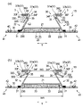
- FIG. 6 (a) is a view corresponding to FIG. 2 of another embodiment of the absorbent article of the present invention
- FIG. 6 (b) is a cross-sectional view (FIG. 6) of the absorbent article shown in FIG. 6 (a) in a natural state. 4 equivalent figure).
- FIG. 7 (a) is a view corresponding to FIG. 2 of still another embodiment of the absorbent article of the present invention
- FIG. 7 (b) is a cross-sectional view of the absorbent article shown in FIG. 7 (a) in a natural state.
- FIG. 4 is a diagram (corresponding to FIG. 4).
- FIG. 8 (a) is a view corresponding to FIG. 2 of still another embodiment of the absorbent article of the present invention
- FIG. 8 (b) is a cross-sectional view of the absorbent article shown in FIG. 8 (a) in a natural state.
- FIG. 4 is a diagram (corresponding to FIG. 4).
- the conventional absorbent article equipped with a leak-proof cuff had room for improvement in terms of the leak-proof performance of the leak-proof cuff.
- the present invention relates to an absorbent article that is excellent in leak-preventing performance of a leak-proof cuff and can effectively prevent lateral leakage.
- the diaper 1 has a vertical direction X corresponding to the front-back direction of the wearer, that is, a direction extending from the ventral side to the dorsal side via the crotch portion, and a lateral direction Y orthogonal to the vertical direction X, and includes the absorber 23. It includes an absorbent main body 2 and a pair of leak-proof cuffs 3 and 3 extending in the vertical direction X arranged by providing a separating portion 39 on a skin-facing surface of the absorbent main body 2.
- the "skin facing surface” is a surface of the absorbent article or its constituent members (for example, an absorbent body) that is directed toward the skin side of the wearer when the absorbent article is worn, that is, relatively of the wearer.
- the side closer to the skin, the “non-skin facing surface” is the surface of the absorbent article or its constituents that faces the opposite side of the skin when the absorbent article is worn, that is, relatively from the wearer's skin.
- the distant side is the term "when worn” as used herein means a state in which the normal proper wearing position, that is, the correct wearing position of the absorbent article is maintained.
- the diaper 1 (absorbent body 2) of the present embodiment has a crotch portion M arranged in the crotch portion of the wearer at the time of wearing and a front portion of the crotch portion M in the vertical direction X, that is, the wearer. It has a ventral portion F arranged on the ventral side of the diaper and a dorsal portion R arranged on the back side of the inseam M in the longitudinal direction X, that is, on the dorsal side of the wearer.
- the inseam M includes an excretion portion facing portion (not shown) that is arranged to face the excretion portion such as the wearer's penis when worn.
- the absorbent body 2 includes an absorber 23, a front surface sheet 21 arranged on the skin-facing surface side of the absorber 23, and a back surface sheet 22 arranged on the non-skin-facing surface side of the absorber 23. , These are integrated by a known joining means such as an adhesive.
- the absorber 23 is interposed between the front surface sheet 21 and the back surface sheet 22, and has a liquid-retaining absorbent core 24 containing a water-absorbent material and an outer surface (skin facing surface and non-skin facing surface) of the absorbent core 24. It is configured to include a core wrap sheet 25 that covers the skin facing surface).
- the absorbent main body 2 of the present embodiment has a rectangular shape in a plan view, extends from the ventral side F to the dorsal side R in the vertical direction X, and the longitudinal direction thereof coincides with the vertical direction X.
- the front surface sheet 21, the back surface sheet 22, and the absorber 23 various types conventionally used for this type of absorbent article can be used without particular limitation.
- the surface sheet 21 for example, a liquid-permeable single-layer or multi-layered non-woven fabric or perforated film can be used.
- the back sheet 22 is a leak-proof sheet, that is, liquid impermeable (property that does not allow liquid to pass through at all) or liquid impermeability (property that does not allow liquid to pass through, although it cannot be said to be liquid impervious).
- a sheet having the above can be used, and for example, a moisture-permeable resin film or a laminate of a resin film and a non-woven fabric can be used.
- Examples of the absorbent core 24 constituting the absorbent body 23 include a fiber stack made by stacking water-absorbent materials such as wood pulp and a water-absorbent polymer, and a sheet-shaped absorbent structure containing the water-absorbent material. Can be used.
- a sheet having liquid permeability can be used, and for example, paper or non-woven fabric can be used.
- the diaper 1 of the present embodiment includes a pair of side flap portions 4 and 4 including members extending outward in the horizontal direction Y from both side edges 23S and 23S along the vertical direction X of the absorber 23. To do.
- the front surface sheet 21 covers the entire surface of the absorber 23 facing the skin
- the back surface sheet 22 covers the entire non-skin facing surface of the absorber 23.
- the 22 further extends outward in the lateral direction Y from the side edges 23S and 23S of the absorber 23, and constitutes the side flap portion 4 together with the leakage-proof cuff forming sheet 30 described later.
- the side flap portion 4 of the present embodiment is located in the non-arranged portion of the absorber 23, and includes the front surface sheet 21, the back surface sheet 22, and the leakage-proof cuff forming sheet 30.
- These plurality of members constituting the side flap portion 4 are joined to each other by known joining means such as an adhesive, a heat seal, and an ultrasonic seal.
- a leg cuff 41 is formed at a portion corresponding to the wearer's leg circumference in each of the pair of side flap portions 4 and 4.
- the leg cuff 41 is a part of the side flap portion 4, and includes at least a leak-proof cuff forming sheet 30 and a leg cuff forming elastic member 42 fixed to the sheet 30 in an extended state. Then, as shown in FIG. 2, the back sheet 22 is included.
- a plurality of (specifically, two) thread-like elastic members 42 extending in the vertical direction X are arranged side by side in the horizontal direction Y on each of the pair of leg cuffs 41, 41 (side flap portions 4, 4).
- Each elastic member 42 extends in the vertical direction X over at least the entire length of the crotch portion M in the vertical direction X.
- the leg cuff 41 typically has an elastic member 42 extended in the vertical direction X, and an adhesive or the like is applied to a sheet (a leak-proof cuff forming sheet 30 and a back surface sheet 22 in the present embodiment) constituting the leg cuff 41. It is manufactured by releasing the elastic member 42 from the stretched state after joining by the joining means of. When the diaper 1 is worn, the leg cuff 41 (side flap portion 4) contracts due to the contraction force of the elastic member 42, and can fit around the wearer's legs.
- elastic members 11 for forming gathers around the waist which are arranged so as to be expandable and contractible in the lateral direction Y, are arranged in the lateral direction Y. It extends laterally from the side flap portion 4 on one side to the side flap portion 4 on the other side.
- the diaper 1 is a so-called deployable disposable diaper, and has a fastening structure 5 used when worn.
- the fastening structure 5 is formed by a pair of fastening tapes 51, 51 arranged on both side edges of the dorsal portion R of the diaper 1 along the vertical direction X, and a ventral portion F of the diaper 1. It is configured to include a target region 53 arranged on a non-skin facing surface (non-skin facing surface of the back sheet 22).
- the fastening tape 51 is provided with a fastening portion 52, and when the diaper 1 is worn, the fastening portion 52 is fastened to the target area 53. In the target area 53, the fastening portion 52 can be detachably fastened.
- the fastening portion 52 is made up of a male member of the mechanical hook-and-loop fastener
- the target region 53 is made up of a female member of the mechanical hook-and-loop fastener.
- each of the pair of leak-proof cuffs 3 and 3 is configured to include a leak-proof cuff forming sheet 30, and the base end portion where the sheet 30 is fixed to another member. 31 and an upright portion 32 in which the seat 30 stands up on the wearer side with the base end portion 31 as a starting point are provided in the lateral direction Y.
- a pair of leak-proof cuff forming sheets 30 are arranged on both sides of the absorbent main body 2 on the skin-facing surface facing the skin along the vertical direction X, and the pair of leak-proof cuff forming sheets 30 are arranged.
- a separating portion 39 is provided between the sheets 30 and 30. The separating portion 39 is located at the center of the absorbent main body 2 (diaper 1) in the lateral direction Y.
- Each leakage-proof cuff forming sheet 30 is arranged so as to straddle the side edge 23S of the absorber 23 in the lateral direction Y, and has a portion overlapping the absorber 23 in a plan view and a portion outside the absorber 23 in the lateral direction Y. It has a portion located in the lateral direction Y in the lateral direction.
- a hydrophobic sheet material is used from the viewpoint of surely fulfilling the role of preventing the leakage of body fluid such as urine to the outside.
- the hydrophobic sheet material for example, as the hydrophobic non-woven fabric, air-through non-woven fabric, spunbonded non-woven fabric, SMS non-woven fabric, SMMS non-woven fabric, SSMS non-woven fabric and the like can be used.
- a hydrophobic resin film and the resin thereof can be used.
- a laminate of the film and the non-woven fabric or the like can be used.
- S means a spunbonded non-woven fabric
- M means a melt-blown non-woven fabric.
- the base end portion 31 is a portion that serves as a standing starting point when the standing portion 32 stands up toward the wearer's skin side when the diaper 1 is worn. More specifically, the base end portion 31 is a portion of the leak-proof cuff forming sheet 30 fixed to the “other member”, which is adjacent to the upright portion 32 in the lateral direction Y, in other words, said. This is the innermost portion of the fixed portion in the lateral direction Y. Further, the "other member” is a member other than the leak-proof cuff forming sheet 30 among the constituent members of the diaper 1, and typically, the sheet 30 is placed on the non-skin facing surface side of the sheet 30. It is a member arranged so as to be in contact with each other, and in the present embodiment, it is a surface sheet 21 as shown in FIG.
- the base end portion 31 is a fixing portion between the leak-proof cuff forming sheet 30 and other members, and is typically provided by an adhesive such as hot melt or a known joining means such as heat fusion. It is formed.
- the base end portion 31 of the present embodiment has a linear shape in a plan view, extends in the vertical direction X over substantially the entire length of the leak-proof cuff forming sheet 30 in the vertical direction X, and also extends in the vertical direction X.
- the absorber 23 is located outside the side edge 23S in the lateral direction and in the vicinity of the side edge 23S.
- the plan view shape of the base end portion 31 is not particularly limited, and may be, for example, a wavy line, a curved line, a zigzag line, or the like in addition to a straight line, and the base end portion 31 is not continuous in one direction (longitudinal direction X). It may be a break line having a structure in which fixed portions and non-fixed portions of the leak-proof cuff forming sheet 30 and other members are alternately arranged in the vertical direction X.
- the upright portion 32 is a non-fixed portion of the leak-proof cuff forming sheet 30 with other members. As shown in FIG. 2, the leak-proof cuff forming sheet 30 constituting the upright portion 32 is bent by the bent portion 30F extending in the vertical direction X.
- the upright portion 32 is divided into a first portion 33 extending from the bent portion 30F to the side edge 30S along the vertical direction X of the sheet 30 and a second portion 34 extending from the bent portion 30F to the base end portion 31 and facing each other.
- the first portion 33 and the second portion 34 have a sheet overlapping portion 36 joined via the joint portion 35.
- the side edge 30S of the leak-proof cuff forming sheet 30 included in the first portion 33 is one of the side edges of the sheet 30 along the vertical direction X, which is relatively close to the center of the lateral direction Y of the diaper 1 (horizontal). The one on the inner side of the direction Y). Of the side edges of the leak-proof cuff forming sheet 30 along the vertical direction X, those relatively far from the center of the horizontal direction Y of the diaper 1 (those on the outer side of the horizontal direction Y) are diapers.
- a side edge portion 1S (see FIG. 1) is formed along the vertical direction X of 1.
- the bent portion 30F has a linear shape extending in the vertical direction X in the unfolded and extended state of the diaper 1 as shown in FIG.
- the sheet overlapping portion 36 has a two-layer structure due to two leak-proof cuff forming sheets 30 arranged so as to face each other.
- the "expanded and stretched state" of the diaper 1 means that the diaper 1 is in the unfolded state as shown in FIG. (Same as the dimensions when expanded in a plane with the influence of the elastic member completely removed).
- the upright portion 32 In the unfolded and extended state of the diaper 1, the upright portion 32 normally falls down without standing up, but in FIG. 2, which shows the same state, the upright portion 32 is upright from the viewpoint of easy explanation.
- the first portion 33 and the second portion 34 are joined at a joint portion 35 closer to the bent portion 30F than the side edge 30S of the leak-proof cuff forming sheet 30. ing.
- the joint portion 35 extends in the vertical direction X.
- extension not only when the joint portion 35 extends continuously in the vertical direction X, but also as shown in FIG. 5, a plurality of joint portions 35 are intermittently arranged in the vertical direction X. , The case where the plurality of joints 35 extend in the vertical direction X as a whole is included (details of the form of FIG. 5 will be described later).
- first portion 33 and the second portion 34 may be joined by an adhesive, or may be joined by fusing a forming material such as a fiber constituting both parts 33 and 34. ..
- the fusion of the first portion 33 and the second portion 34 can be carried out by using a known fusion means such as a heat seal or an ultrasonic seal.
- a plurality of (four in the present embodiment) elastic members 37 for forming leak-proof cuffs extending in the vertical direction X are arranged side by side in the horizontal direction Y in a state of being expandable and contractible in the vertical direction X.
- the sheet overlapping portion 36 has elasticity in the vertical direction X.
- the elastic member 37 for forming the leak-proof cuff is preferably thread-shaped, but may be strip-shaped instead. Further, in the present embodiment, a plurality of elastic members 37 for forming a leak-proof cuff are arranged in each sheet overlapping portion 36, but the number of the elastic members 37 is not particularly limited and may be one.
- the second portion 34 (the portion extending from the bent portion 30F to the base end portion 31 in the standing portion 32) is a bent portion 34F extending in the vertical direction X in the horizontal direction Y. It is bent outward, and the sheet overlapping portion 36 extends outward in the lateral direction Y from the bent portion 34F.
- the leak-proof cuff 3 is typically produced by fixing the leak-proof cuff-forming elastic member 37 to the leak-proof cuff-forming sheet 30 in an stretched state and then releasing the stretched state. Due to such a manufacturing method, a large number of wrinkles are formed on the surface of the sheet overlapping portion 36 which can come into contact with the skin of the wearer of the diaper 1, more specifically, on the surfaces of the first portion 33 and the second portion 34, respectively. Exists. The wrinkles on the surface of the sheet overlapping portion 36 are arranged substantially regularly in the vertical direction X.
- the standing portion 32 is present at least in the inseam M. This is because the part of the diaper 1 where excrement is concentrated and lateral leakage is particularly problematic is the inseam M. As shown in FIG. 1, the standing portion 32 of the present embodiment extends over the entire length of the crotch portion M in the longitudinal direction X, and further extends to both the ventral side portion F and the dorsal side portion R.
- standing inhibition portions 38 are formed on both outer sides of the standing portions 32 of each of the pair of leak-proof cuffs 3 and 3 in the vertical direction X.
- the standing portion 32 is sandwiched between the standing blocking portion 38 on one end side (ventral side F side) and the standing blocking portion 38 on the other end side (dorsal side R side) in the longitudinal direction X.
- a portion of the leak-proof cuff forming sheet 30 that exists at the same position as the standing portion 32 (that is, a non-fixed portion with another member) in the lateral direction Y overlaps with the absorber 23 in a plan view. Is fixed to another member (the surface sheet 21 in the present embodiment), so that the standing portion 38 does not stand even if the standing portion 32 stands up.
- the standing portions 32 of each of the pair of leak-proof cuffs 3 and 3 raise the base end portion 31 by the contraction force of the elastic member 37 for forming the leak-proof cuff arranged in the sheet overlapping portion 36.
- a pair of leak-proof walls composed of the upright portions 32 are formed on both sides of the absorbent body 2 at least in the inseam M along the vertical direction X of the skin-facing surface.
- This pair of leak-proof walls blocks excrement such as urine and feces excreted on the skin-facing surface of the diaper 1 and prevents the excrement from leaking to the outside of the diaper 1 in the lateral direction Y, so-called lateral leakage. To do.
- the central portion (the portion including the inseam M) of the diaper 1 which is the arrangement portion of the elastic member 37 is not formed due to the contraction force of the elastic member 37 for forming the leak-proof cuff.
- the diaper 1 is curved so as to be convex on the skin-facing surface side (back surface sheet 22 side), in other words, concave on the skin-facing surface side (front surface sheet 21 side). In this way, the diaper 1 is transformed into a boat shape as a whole. Since such a boat-shaped diaper 1 easily follows the shape of the crotch portion of the wearer, the seat overlapping portion 36 of the upright portion 32 in the upright state of the diaper 1 fits well on the wearer's skin and adheres thereto. Therefore, the lateral leakage prevention function of the leakage prevention cuff 3 can be effectively exhibited.
- the first portion 33 of the upright portion 32 that is, the portion extending from the bent portion 30F in the upright portion 32 to the side edge 30S of the leakage-proof cuff forming sheet 30
- the sheet 30 has a free edge portion 330, which is a portion extending from the joint portion 35 in a non-fixed state to another member.
- the free edge portion 330 of the first portion 33 extends in the vertical direction X over the entire length of the vertical direction X of the standing portion 32.
- the free edge portion 330 of the first portion 33 is at least in the natural state of the diaper 1 as shown in FIG. 3, as shown in FIG. 4, the stretchable portion 360 (the bent portion 30F in the first portion 33) starts from the joint portion 35.
- the pocket structure 3P is formed between the warped free edge portion 330 and the telescopic portion 360. Since the state of the diaper 1 when worn is close to the natural state, such a pocket structure 3P extends in the vertical direction X along the standing portion 32 in the standing state when the diaper 1 is worn.
- the "natural state" of the diaper 1 is a state in which no external force is applied to the diaper 1 (relaxed state), and more specifically, the diaper 1 has elasticity in the vertical direction X.
- This is the state when the expansion amount of the expansion / contraction portion 360 of the leakage cuff 3 (the arrangement portion of the elastic member 37 for forming the leakage prevention cuff fixed in the extension state) is 0 (zero).
- the amount of expansion of the expansion / contraction portion 360 is 0 means that all of the elastic members 37 for forming the leak-proof cuff existing in the expansion / contraction portion 360 are not elongated, and the length of the expansion / contraction portion 360 in the vertical direction X. Is the shortest state.
- the first portion 33 is located inside the second portion 34 in the lateral direction Y.
- the first portion 33 is relatively close to the center of the lateral Y of the diaper 1
- the second portion 34 is relatively far from the center of the lateral Y of the diaper 1.
- the pocket structure 3P formed by the warp of the free edge portion 330 of the first portion 33 is as shown in FIG. It exists inward in the lateral direction Y with respect to the leakage-proof cuff 3 (standing portion 32), that is, exists in a region sandwiched between the pair of leakage-proof cuffs 3, 3.
- Such a pocket structure 3P formed inside the leak-proof cuff 3 serves as a barrier for excrement that tries to get over the leak-proof cuff 3, and can prevent the inconvenience that the excrement gets over the leak-proof cuff 3 in advance. ..
- the free edge portion 330 of the first portion 33 extends from the joint portion 35 between the first portion 33 and the second portion 34 constituting the sheet overlapping portion 36 in a non-fixed state to other members.
- the extension length L1 (see FIG. 2) of the free edge portion 330 of the first portion 33 from the joint portion 35 is the length L2 (see FIG. 2) extending from the joint portion 35 to the base end portion 31 in the second portion 34. It is required to be 0.05 times or more.
- the lengths L1 and L2 are the design dimensions (the same as the dimensions when the sheet (leakage-proof cuff forming sheet 30) forming the relevant portion is extended and expanded in a plane with the influence of the elastic member completely eliminated). It is the length in the expanded state until it becomes. If L1 / L2 is less than 0.05 times, the free edge portion 330 is too short with respect to the length L2 related to the standing height of the standing portion 32. The effect of the pocket structure 3P is not sufficiently obtained, and the effect of improving the leakage prevention performance of the leakage prevention cuff 3 is not sufficiently obtained.
- L1 / L2 is preferably 0.1 times or more, more preferably 0.15 times or more, still more preferably 0.15 times or more. It is 0.2 times or more.
- the upper limit of L1 / L2 is not particularly limited, but is preferably 0.9 times or less, more preferably 0.8 times or less, and further, from the viewpoint of exerting the function of the free edge portion 330 as a pocket structure. It is preferably 0.7 times or less.
- the extension length L1 (see FIG. 2) of the free edge portion 330 of the first portion 33 from the joint portion 35 is preferably 2 mm or more, more preferably 4 mm or more, and preferably 25 mm or less, more preferably 20 mm or less. Is.
- the length L2 from the joint portion 35 to the base end portion 31 in the second portion 34 is preferably 5 mm or more, more preferably 10 mm or more, and preferably 30 mm or less, more preferably 25 mm or less.
- the base end portion 31 of one of the leak-proof cuffs 3 The separation distance between one and the other (shortest separation distance) is W1, the separation distance between the free edge 330 of one leak-proof cuff forming sheet 30 and that of the other (shortest separation distance) is W2, and one sheet overlaps.
- W3 the separation distance between the portion 36 and the other portion is W3
- W2 ⁇ W1 and W2 ⁇ W3 are established in the natural state of the diaper 1 as shown in FIG. With the establishment of such a magnitude relationship, the pocket structure 3P can sufficiently function as a barrier for excrement that tries to get over the leak-proof cuff 3 when the diaper 1 is worn.
- the ratio of the separation distance W1 to the separation distance W2 is preferably 1.01 or more, more preferably 1.05 or more, and preferably 2.0 or less, more preferably 1.01 or more, more preferably 1.05 or more, and more preferably 2.0 or less as the former / latter, assuming the former> the latter. Is 1.5 or less.
- the ratio of the separation distance W3 to the separation distance W2 is preferably 1.01 or more, more preferably 1.05 or more, and preferably 1.9 or less, more preferably 1.01 or more, more preferably 1.05 or more, and more preferably 1.9 or less as the former / latter, assuming the former> the latter. Is 1.4 or less.
- the separation distance W1 is preferably 115 mm or more, more preferably 120 mm or more, and preferably 145 mm or less, more preferably 140 mm or less.
- the separation distance W2 is preferably 75 mm or more, more preferably 80 mm or more, and preferably 135 mm or less, more preferably 130 mm or less.
- the separation distance W3 is preferably 100 mm or more, more preferably 105 mm or more, and preferably 140 mm or less, more preferably 135 mm or less.
- a plurality of (four in the present embodiment) elastic members for forming a leak-proof cuff extending in the vertical direction X between the first portion 33 and the second portion 34.
- the diapers 1 are arranged side by side in the horizontal direction Y in a state where the 37s can be expanded and contracted in the vertical direction X, they are located at the innermost side of the plurality of elastic members 37 in the horizontal direction Y when the diaper 1 is worn.
- the thing (the one indicated by the reference numeral 37a in the figure) has a larger stress than the one located at the outermost side in the lateral direction Y (the one indicated by the reference numeral 37b in the figure).
- the diaper 1 when the diaper 1 is worn, the magnitude relationship of "stress of the innermost elastic member 37a in the lateral direction> stress of the outermost elastic member 37b in the lateral direction" is established, so that the diaper extends from the joint portion 35.
- the free edge portion 330 of the first portion 33 is likely to warp, and the pocket structure 3P is likely to be formed.
- the above-mentioned "when wearing diaper 1 (absorbent article)" is a state in which the "length of the cuff in the vertical direction" is in the range of 30 or more and 90 or less.
- the “longitudinal length of the cuff” referred to here is based on the vertical length of the leak-proof cuff (the leak-proof cuff 3 in the diaper 1) provided in the absorbent article in the maximum extended state. Is the relative vertical length of.
- the vertical length of the cuff is typically the shortest when the leak-proof cuff is in its natural state (no external force is applied), but it is not zero.
- the ratio of the stress of the elastic member 37a on the innermost side in the lateral direction to the stress on the elastic member 37b on the outermost side in the lateral direction when the diaper 1 is worn is preferably 1 as the former / the latter on the premise that the former> the latter. It is 0.01 or more, more preferably 1.05 or more, and preferably 3 or less, more preferably 2 or less.
- the stress of the innermost elastic member 37a in the lateral direction when the diaper 1 is worn is preferably 0.03 N or more, more preferably 0.06 N or more, and preferably 0.24 N or less, more preferably 0.2 N. It is as follows.
- the stress of the outermost elastic member 37b in the lateral direction when the diaper 1 is worn is preferably 0.02 N or more, more preferably 0.05 N or more, and preferably 0.2 N or less, more preferably 0.16 N. It is as follows.
- the stress of the elastic member including the leak-proof cuff forming elastic member 37 is measured by the following method.
- the elastic member for forming a leak-proof cuff to be measured (the elastic member 37a located on the innermost side in the lateral direction Y and the elastic member 37b located on the outermost side in the lateral direction Y). Cut out and use as a measurement sample.
- the length of the measurement sample in the longitudinal direction (length in the longitudinal direction X) is 100 mm.
- the measurement sample is sandwiched between the chucks of the Tencilon universal testing machine (RTC-1210A) manufactured by ORIENTEC Co., Ltd., and the distance between the chucks is widened at a speed of 300 mm / min to extend the measurement sample in the longitudinal direction (longitudinal direction).
- the distance between the chucks is narrowed at a speed of 300 mm / min to shrink the measurement sample to a predetermined length, and the stress (shrinking stress) at that time (unit:: N) is measured.
- the stress is clear from the above definition of "when the diaper 1 (absorbent article) is worn".
- the vertical length of the cuff in the maximum extension state of the measurement sample is 100
- the contraction stress is such that the vertical length of the cuff is 30 or more and 90 or less. Therefore, in this measurement, the measurement sample is used.
- the maximum extension state corresponding to the cuff vertical length 100 is contracted to the length corresponding to the cuff vertical length 30.
- the thickness of the elastic member 37a on the innermost side in the lateral direction is set to the elastic member on the outermost side in the lateral direction. There is a method of making it larger than that of 37b.
- first portion side fusion area the area of the joint portion 35 when the joint portion 35 is observed from the second portion 34 side.
- FIG. 5 shows an example of a form in which the first partial side fusion area and the second partial side fusion area are different.
- FIG. 5 shows a case where the joint portion 35 (fused portion) of one of the pair of leakage-proof cuffs 3 and 3 in the diaper 1 is observed along the extending direction (longitudinal direction X).
- FIG. 5 (a) when the joint portion 35 is observed from the outside of the lateral direction Y (the side relatively far from the center of the lateral direction Y of the diaper 1), FIG. 5 (b) shows the joint portion 35 beside the joint portion 35. This is a case of observing from the inside of the direction Y (the side relatively close to the center of the lateral direction Y of the diaper 1).
- FIG. 5A shows the joint portion 35 on the second portion 34 side (horizontal direction Y). It is a case where the joint portion 35 is observed along the vertical direction X from the outside), and FIG. 5B is a case where the joint portion 35 is observed from the first portion 33 side (inside the horizontal direction Y) along the vertical direction X. ..
- a plurality of joint portions 35 are intermittently arranged in the vertical direction X in both the observation from the first portion 33 side and the observation from the second portion 34 side.
- the area (fused area) of each joint 35 is larger when observed from the second portion 34 side than when observed from the first portion 33, and is leak-proof cuff 3 (for leak-proof cuff formation).
- the unit area of the sheet 30 specifically, for example, a rectangular area in a plan view having a length of 10 mm in both the vertical direction X and the horizontal direction Y (corresponding to the "measurement piece” in the method for measuring the fusion area described later). In the region), the magnitude relationship of "first partial side fusion area ⁇ second partial side fusion area" is established.
- the fused area (joint area) is measured by the following method.
- a leak-proof cuff 3 (leak-proof cuff forming sheet 30) is cut out from the diaper 1, and a 10 mm ⁇ 10 mm rectangular shape in a plan view including the joint portion 35 (fused portion) is cut out from the cut-out leak-proof cuff 3 and measured.
- the fusion area is measured from the contour of the joint portion 35 using, for example, VHX-1000 manufactured by KEYENCE as an image analysis device. To do.
- the warp of the free edge portion 330 of the first portion 33 can be promoted.
- the "first portion” is contrary to the form shown in FIG.
- the warp of the free edge portion 330 of the first portion 33 can be promoted.
- the difference between the first partial side fusion area and the second partial side fusion area means that when the joint portion 35 (fused portion) is formed, the first portion 33 side and the second portion are to be formed with respect to the planned formation portion. It can be carried out by performing the welding process from both sides of the portion 34, or can be carried out by performing the fusion process from only one of the first portion 33 side and the second portion 34 side.
- Known fusion means such as heat seal and ultrasonic seal can be used for the fusion process.
- fusion processing is performed from only one of the first portion 33 side and the second portion 34 side to make the first portion side fusion area and the second portion side fusion area different, as a fusion means. It is preferable to use a fusion means using ultrasonic waves such as an ultrasonic seal.
- FIG. 6 to 8 show other embodiments of the absorbent article of the present invention.
- the embodiments described later will mainly be described with components different from those of the diaper 1 described above, and similar components will be designated by the same reference numerals and description thereof will be omitted.
- the description of the diaper 1 is appropriately applied to the components not particularly described.
- the second portion 34 of the standing portion 32 was bent outward in the lateral direction Y (see FIGS. 2 and 4), but in the diaper 1A shown in FIG. 6, the second portion 34 was bent.
- the entire standing portion 32 extends in one direction (from the outer side to the inner side in the lateral direction Y) from the base end portion 31.
- two elastic members 37 for forming a leak-proof cuff are arranged in each of the pair of sheet overlapping portions 36, 36, and the number of the elastic members 37 arranged in each of the sheet overlapping portions 36 is larger than that of the diaper 1. Few.
- the diaper 1A is configured in the same manner as the diaper 1 except for the above points, and W2 ⁇ W1 and W2 ⁇ W3 are established in the natural state.
- Diaper 1A has basically the same effect as diaper 1, but from the viewpoint of surely preventing the inconvenience of excrement overcoming the leak-proof cuff 3, the second part 34 is bent like diaper 1. It is preferable that the portion 34F is bent outward in the lateral direction Y.
- the first portion 33 is located outside the second portion 34 in the lateral direction Y, and the arrangement of both portions 34A and 34B is opposite to that of the diapers 1 and 1A.
- the first portion 33 is relatively far from the center of the lateral direction Y of the diaper 1, and the second portion 34 is relatively close to the center of the lateral direction Y of the diaper 1. Therefore, as shown in FIG. 7B, the pocket structure 3P formed by the warp of the free edge portion 330 of the first portion 33 is outward in the lateral direction Y with respect to the leakage-proof cuff 3 (standing portion 32).
- the pocket structure 3P formed on the outside of the leak-proof cuff 3 captures the excrement that has passed over the leak-proof cuff 3, and the excrement moves outward in the lateral direction Y from the pocket structure 3P. It is possible to prevent lateral leakage.
- the free edge portion 330 of the first portion 33 extends from the joint portion 35 between the first portion 33 and the second portion 34 constituting the sheet overlapping portion 36 in a non-fixed state to other members.
- the base end portion 31 of one of the leak-proof cuffs 3 The separation distance between and the other is W1, the separation distance between the free edge 330 of one leak-proof cuff forming sheet 30 and that of the other is W2, and the separation distance between one sheet overlapping portion 36 and that of the other (the shortest).
- W3 it is preferable that W2> W1 and W2> W3 are satisfied in the natural state of the diaper as shown in FIG. With the establishment of such a magnitude relationship, the pocket structure 3P can sufficiently function as a pocket for catching excrement that has passed over the leak-proof cuff 3 when the diaper 1 is worn.
- the ratio of the separation distance W1 to the separation distance W2 is preferably 0.6 or more, more preferably 0.65 or more, and preferably 0.99 or less, more preferably 0.6 or more, more preferably 0.65 or more, and more preferably 0.99 or less as the former / latter, assuming the former ⁇ the latter. Is less than or equal to 0.95.
- the ratio of the separation distance W3 to the separation distance W2 is preferably 0.55 or more, more preferably 0.6 or more, and preferably 0.95 or less, more preferably 0.55 or more, more preferably 0.6 or more, and more preferably 0.95 or less as the former / latter, assuming the former ⁇ the latter. Is less than or equal to 0.9.
- the separation distance W1 is preferably 115 mm or more, more preferably 120 mm or more, and preferably 145 mm or less, more preferably 140 mm or less.
- the separation distance W2 is preferably 120 mm or more, more preferably 125 mm or more, and preferably 180 mm or less, more preferably 175 mm or less.
- the separation distance W3 is preferably 100 mm or more, more preferably 105 mm or more, and preferably 140 mm or less, more preferably 135 mm or less.
- the second portion 34 of the upright portion 32 was bent outward in the lateral direction Y at the bent portion 34F (see FIG. 7), but in the diaper 1C shown in FIG. 8, the second portion 34 is bent.
- the entire upright portion 32 extends from the base end portion 31 in one direction (the direction from the outside to the inside in the lateral direction Y).
- two elastic members 37 for forming a leak-proof cuff are arranged in each of the pair of sheet overlapping portions 36, 36, and the number of the elastic members 37 arranged in each of the sheet overlapping portions 36 is larger than that in the diaper 1B. Few.
- the diaper 1C is configured in the same manner as the diaper 1B except for the above points, and W2> W1 and W2> W3 are established in the natural state.
- the diaper 1C has the same effect as the diaper 1B.
- the absorbable article of the present invention broadly includes articles used for absorbing body fluids (urine, menstrual blood, loose stool, sweat, etc.) discharged from the human body, and other than the deployable disposable diaper as in the above embodiment, for example, It may include pants-type disposable diapers, urine absorbing pads, sanitary napkins, sanitary shorts, and the like. The following additional notes are further disclosed with respect to the embodiments of the present invention.
- ⁇ 1> It has a vertical direction corresponding to the front-back direction of the wearer and a horizontal direction orthogonal to the vertical direction, and is arranged so as to provide a separation portion between an absorbent body having an absorber and a skin-facing surface of the absorbent body.
- An absorbent article comprising a pair of leak-proof cuffs extending in the vertical direction.
- Each of the pair of leak-proof cuffs is configured to include a leak-proof cuff forming sheet, and the leakage-proof cuff forming sheet is fixed to another member at a base end portion and the base end portion as a starting point.
- the leak-proof cuff forming sheet has an upright portion that stands up on the wearer side.
- the leak-proof cuff forming sheet constituting the upright portion is bent at the bent portion extending in the vertical direction.
- the upright portion is divided into a first portion extending from the bent portion to the side edge of the leak-proof cuff forming sheet along the vertical direction and a second portion extending from the bent portion to the base end portion, and facing each other. It has a sheet overlapping portion in which the first portion and the second portion are joined via a joint portion.
- the first portion has a free edge portion, which is a portion of the leak-proof cuff forming sheet extending from the joint portion in a non-fixed state to another member.
- the extension length L1 of the free edge portion from the joint portion is 0.1 times or more and 0.9 times or less, preferably 0.
- ⁇ 4> The absorbency according to any one of ⁇ 1> to ⁇ 3>, wherein the length L2 from the joint portion to the base end portion in the second portion is 5 mm or more and 30 mm or less, preferably 10 mm or more and 25 mm or less. Goods.
- ⁇ 8> The absorbent article according to ⁇ 6> or ⁇ 7>, wherein the ratio of W3 to W2 (W3 / W2) is 1.01 or more and 1.9 or less, preferably 1.05 or more and 1.4 or less. ..
- W1 and W2> W3 are established in the natural state of the absorbent article, where the separation distance of the leak cuff from the sheet overlapping portion is W3.
- W1 / W2 is 0.6 or more and 0.99 or less, preferably 0.65 or more and 0.95 or less.
- the ratio of W3 to W2 (W3 / W2) is 0.55 or more and 0.95 or less, preferably 0.6 or more and 0.9 or less. ..
- a plurality of elastic members for forming a leak-proof cuff are arranged side by side in the lateral direction between the first portion and the second portion.
- the innermost elastic member located on the innermost side in the lateral direction is the outermost elastic member located on the outermost side in the lateral direction among the plurality of elastic members for forming a leak-proof cuff.
- ⁇ 14> The absorbent article according to ⁇ 13>, wherein the ratio of the stress of the innermost elastic member to the stress of the outermost elastic member is 1.01 or more and 3 or less, preferably 1.05 or more and 2 or less.
- the joint portion is a fusion portion in which the first portion and the second portion are fused, and the area of the fusion portion when the fusion portion is observed from the first portion side and the fusion portion.
- Examples 1 and 2 Comparative Example 1
- a deployable disposable diaper having the same basic configuration as the diaper 1 shown in FIG. 1, that is, an absorbent article in which the first portion is located laterally inward from the second portion in the upright portion of the leak-proof cuff was produced.
- a deployable disposable diaper we prepared a Mary's tape type S size (made in 2017, registered trademark) manufactured by Kao Corporation, and adjusted the dimensions of each part of the leak-proof cuff of the prepared diaper as appropriate.
- the deployable disposable diapers of Examples and Comparative Examples were prepared.
- Examples 3 to 4, Comparative Example 2 A deployable disposable diaper having the same basic configuration as the diaper 1B shown in FIG. 7, that is, an absorbent article in which the first portion is located laterally outward from the second portion in the upright portion of the leak-proof cuff was produced.
- a deployable disposable diaper we prepared a Mary's tape type S size (made in 2017, registered trademark) manufactured by Kao Corporation, and adjusted the dimensions of each part of the leak-proof cuff of the prepared diaper as appropriate.
- the deployable disposable diapers of Examples and Comparative Examples were prepared.
- the model doll provided with the excretion point was put on the diaper to be evaluated, and the lateral leakage prevention property of the leakage-proof cuff of the diaper was evaluated by the following method. First, the diaper was attached to the model doll, and the model doll was tilted 90 ° so as to be turned sideways. In this state, 10 g of pseudo loose stool was injected into the site corresponding to the excretion point in the diaper.
- the composition of the pseudo loose stool is 22.5% by mass of bentonite, 0.5% by mass of a surfactant (poise 530, solid content 40% by mass, manufactured by Kao Co., Ltd.), and an aqueous solution of Emargen 130K 0.03% by mass (manufactured by Kao Co., Ltd.). 1.5% by mass, ion-exchanged water 75.5% by mass, viscosity 40 mPa ⁇ s (23 ° C, vibration viscometer: manufactured by A & D Co., Ltd., SV-10), surface tension 55 mN / It was m.
- the model doll Immediately after injecting the pseudo loose stool, the model doll is placed upright, and when the diaper located in the inseam of the model doll is pressed against the model doll with a pressure of 3 kPa, the pseudo loose stool laterally outwards from the leak-proof cuff of the diaper. It was observed whether or not it leaked.
- the above operation was performed 10 times for each evaluation target, and the probability that lateral leakage could be prevented (the ratio of the number of times that pseudo loose stool leakage was not observed to the total of 10 times) was defined as lateral leakage prevention. The larger this value is, the better the lateral leakage prevention property of the leakage prevention cuff is, and the higher the evaluation is.
- an absorbent article which is excellent in the leakage prevention performance of the leakage prevention cuff and can effectively prevent lateral leakage.
Landscapes
- Health & Medical Sciences (AREA)
- Epidemiology (AREA)
- Engineering & Computer Science (AREA)
- Biomedical Technology (AREA)
- Heart & Thoracic Surgery (AREA)
- Vascular Medicine (AREA)
- Life Sciences & Earth Sciences (AREA)
- Animal Behavior & Ethology (AREA)
- General Health & Medical Sciences (AREA)
- Public Health (AREA)
- Veterinary Medicine (AREA)
- Absorbent Articles And Supports Therefor (AREA)
Priority Applications (2)
| Application Number | Priority Date | Filing Date | Title |
|---|---|---|---|
| EP20883346.7A EP4005544B1 (en) | 2019-11-01 | 2020-10-26 | Absorbent article |
| CN202080061245.9A CN114302702B (zh) | 2019-11-01 | 2020-10-26 | 吸收性物品 |
Applications Claiming Priority (2)
| Application Number | Priority Date | Filing Date | Title |
|---|---|---|---|
| JP2019200004A JP7332436B2 (ja) | 2019-11-01 | 2019-11-01 | 吸収性物品 |
| JP2019-200004 | 2019-11-01 |
Publications (1)
| Publication Number | Publication Date |
|---|---|
| WO2021085361A1 true WO2021085361A1 (ja) | 2021-05-06 |
Family
ID=75713940
Family Applications (1)
| Application Number | Title | Priority Date | Filing Date |
|---|---|---|---|
| PCT/JP2020/040048 Ceased WO2021085361A1 (ja) | 2019-11-01 | 2020-10-26 | 吸収性物品 |
Country Status (4)
| Country | Link |
|---|---|
| EP (1) | EP4005544B1 (https=) |
| JP (1) | JP7332436B2 (https=) |
| CN (1) | CN114302702B (https=) |
| WO (1) | WO2021085361A1 (https=) |
Families Citing this family (1)
| Publication number | Priority date | Publication date | Assignee | Title |
|---|---|---|---|---|
| JP2024122498A (ja) * | 2023-02-28 | 2024-09-09 | 王子ホールディングス株式会社 | 吸収性物品 |
Citations (7)
| Publication number | Priority date | Publication date | Assignee | Title |
|---|---|---|---|---|
| JPH05293134A (ja) * | 1992-04-21 | 1993-11-09 | Uni Charm Corp | 使い捨てオムツ |
| JPH0810287A (ja) * | 1994-06-30 | 1996-01-16 | Honshu Paper Co Ltd | 使い捨て吸収性製品用表面材とその製法及びポケット構造を持つ使い捨て吸収性製品 |
| JPH1128224A (ja) * | 1998-06-08 | 1999-02-02 | Shiseido Co Ltd | 吸収性物品の製造方法 |
| JPH11285510A (ja) | 1998-04-02 | 1999-10-19 | Kao Corp | 使い捨ておむつ |
| JP2008307223A (ja) | 2007-06-14 | 2008-12-25 | Hakujuji Co Ltd | 使い捨て吸収性物品 |
| JP2009178274A (ja) * | 2008-01-30 | 2009-08-13 | Uni Charm Corp | 吸収性物品 |
| JP2011050501A (ja) | 2009-08-31 | 2011-03-17 | Uni Charm Corp | 着用物品 |
Family Cites Families (18)
| Publication number | Priority date | Publication date | Assignee | Title |
|---|---|---|---|---|
| JPH07136212A (ja) * | 1993-11-17 | 1995-05-30 | Shiseido Co Ltd | 吸収性物品およびその製造方法 |
| GB2296445B (en) * | 1994-12-27 | 1998-12-30 | Kao Corp | Sanitary napkin |
| JP3434695B2 (ja) * | 1997-12-26 | 2003-08-11 | ユニ・チャーム株式会社 | 使い捨ておむつ |
| JP3638094B2 (ja) * | 1999-06-07 | 2005-04-13 | ユニ・チャーム株式会社 | 防漏カフを有する吸収性物品 |
| JP4219069B2 (ja) * | 1999-11-10 | 2009-02-04 | 花王株式会社 | 吸収性物品 |
| JP3847046B2 (ja) * | 2000-03-14 | 2006-11-15 | ユニ・チャーム株式会社 | 吸収性物品 |
| CN1253137C (zh) * | 2001-12-21 | 2006-04-26 | 宝洁公司 | 具有阻挡腿箍和用弹性线制成的外腿箍的一次性吸收制品 |
| JP3994377B2 (ja) * | 2002-01-21 | 2007-10-17 | 大王製紙株式会社 | 吸収性物品 |
| JP4352027B2 (ja) * | 2005-06-13 | 2009-10-28 | 大王製紙株式会社 | 吸収性物品 |
| JP2009136600A (ja) * | 2007-12-10 | 2009-06-25 | Kao Corp | 吸収性物品 |
| JP5623828B2 (ja) * | 2010-08-31 | 2014-11-12 | 大王製紙株式会社 | 吸収性物品 |
| JP6037660B2 (ja) * | 2012-05-28 | 2016-12-07 | 大王製紙株式会社 | 吸収性物品 |
| JP6211777B2 (ja) * | 2013-03-18 | 2017-10-11 | 株式会社リブドゥコーポレーション | 吸収性物品 |
| JP2014198074A (ja) * | 2013-03-29 | 2014-10-23 | 日本製紙クレシア株式会社 | フラップを有する吸収性物品 |
| JP5591413B1 (ja) * | 2014-04-14 | 2014-09-17 | ユニ・チャーム株式会社 | 吸収性物品 |
| JP6373092B2 (ja) * | 2014-06-30 | 2018-08-15 | ユニ・チャーム株式会社 | 吸収性物品 |
| US12036103B2 (en) * | 2017-12-22 | 2024-07-16 | Kao Corporation | Disposable diaper |
| JP7174534B2 (ja) * | 2018-04-24 | 2022-11-17 | 花王株式会社 | 吸収パッド |
-
2019
- 2019-11-01 JP JP2019200004A patent/JP7332436B2/ja active Active
-
2020
- 2020-10-26 WO PCT/JP2020/040048 patent/WO2021085361A1/ja not_active Ceased
- 2020-10-26 CN CN202080061245.9A patent/CN114302702B/zh active Active
- 2020-10-26 EP EP20883346.7A patent/EP4005544B1/en active Active
Patent Citations (7)
| Publication number | Priority date | Publication date | Assignee | Title |
|---|---|---|---|---|
| JPH05293134A (ja) * | 1992-04-21 | 1993-11-09 | Uni Charm Corp | 使い捨てオムツ |
| JPH0810287A (ja) * | 1994-06-30 | 1996-01-16 | Honshu Paper Co Ltd | 使い捨て吸収性製品用表面材とその製法及びポケット構造を持つ使い捨て吸収性製品 |
| JPH11285510A (ja) | 1998-04-02 | 1999-10-19 | Kao Corp | 使い捨ておむつ |
| JPH1128224A (ja) * | 1998-06-08 | 1999-02-02 | Shiseido Co Ltd | 吸収性物品の製造方法 |
| JP2008307223A (ja) | 2007-06-14 | 2008-12-25 | Hakujuji Co Ltd | 使い捨て吸収性物品 |
| JP2009178274A (ja) * | 2008-01-30 | 2009-08-13 | Uni Charm Corp | 吸収性物品 |
| JP2011050501A (ja) | 2009-08-31 | 2011-03-17 | Uni Charm Corp | 着用物品 |
Also Published As
| Publication number | Publication date |
|---|---|
| CN114302702A (zh) | 2022-04-08 |
| CN114302702B (zh) | 2022-11-18 |
| EP4005544B1 (en) | 2025-12-03 |
| EP4005544A4 (en) | 2023-07-26 |
| JP7332436B2 (ja) | 2023-08-23 |
| EP4005544A1 (en) | 2022-06-01 |
| JP2021069864A (ja) | 2021-05-06 |
Similar Documents
| Publication | Publication Date | Title |
|---|---|---|
| JP5964146B2 (ja) | 吸収性物品 | |
| JP5577085B2 (ja) | パンツ型使い捨ておむつ | |
| JP2016077880A (ja) | パンツ型使い捨ておむつ | |
| JP5340696B2 (ja) | 吸収性物品 | |
| JP7101188B2 (ja) | 使い捨ておむつ | |
| WO2021085361A1 (ja) | 吸収性物品 | |
| CN214073877U (zh) | 吸收性物品 | |
| JP5064982B2 (ja) | 吸収性物品 | |
| TW201740896A (zh) | 用後即棄式紙尿褲 | |
| JP4920892B2 (ja) | 使い捨てのパンツ型着用物品 | |
| JP2021006246A (ja) | 吸収体及び吸収性物品 | |
| WO2020262210A1 (ja) | 吸収性物品 | |
| JP6265527B2 (ja) | 吸収性物品 | |
| WO2022265090A1 (ja) | 吸収性物品 | |
| JP3243460U (ja) | 吸収性物品 | |
| JP5306793B2 (ja) | 着用物品 | |
| JP5525255B2 (ja) | 使い捨ておむつ | |
| RU2793095C1 (ru) | Впитывающее изделие | |
| JP2008161206A (ja) | 使い捨ての着用物品 | |
| TW201740895A (zh) | 用後即棄式紙尿褲 | |
| JP3241886U (ja) | 吸収体及び吸収性物品 | |
| JP6291180B2 (ja) | 吸収性物品 | |
| JP7025496B1 (ja) | 吸収性物品 | |
| JP7438870B2 (ja) | 吸収性物品 | |
| JP5976405B2 (ja) | パンツ型吸収性物品 |
Legal Events
| Date | Code | Title | Description |
|---|---|---|---|
| 121 | Ep: the epo has been informed by wipo that ep was designated in this application |
Ref document number: 20883346 Country of ref document: EP Kind code of ref document: A1 |
|
| ENP | Entry into the national phase |
Ref document number: 2020883346 Country of ref document: EP Effective date: 20220228 |
|
| NENP | Non-entry into the national phase |
Ref country code: DE |
|
| WWG | Wipo information: grant in national office |
Ref document number: 2020883346 Country of ref document: EP |