WO2021085361A1 - 吸収性物品 - Google Patents
吸収性物品 Download PDFInfo
- Publication number
- WO2021085361A1 WO2021085361A1 PCT/JP2020/040048 JP2020040048W WO2021085361A1 WO 2021085361 A1 WO2021085361 A1 WO 2021085361A1 JP 2020040048 W JP2020040048 W JP 2020040048W WO 2021085361 A1 WO2021085361 A1 WO 2021085361A1
- Authority
- WO
- WIPO (PCT)
- Prior art keywords
- leak
- absorbent article
- proof
- sheet
- proof cuff
- Prior art date
Links
Images


Classifications
-
- A—HUMAN NECESSITIES
- A61—MEDICAL OR VETERINARY SCIENCE; HYGIENE
- A61F—FILTERS IMPLANTABLE INTO BLOOD VESSELS; PROSTHESES; DEVICES PROVIDING PATENCY TO, OR PREVENTING COLLAPSING OF, TUBULAR STRUCTURES OF THE BODY, e.g. STENTS; ORTHOPAEDIC, NURSING OR CONTRACEPTIVE DEVICES; FOMENTATION; TREATMENT OR PROTECTION OF EYES OR EARS; BANDAGES, DRESSINGS OR ABSORBENT PADS; FIRST-AID KITS
- A61F13/00—Bandages or dressings; Absorbent pads
- A61F13/15—Absorbent pads, e.g. sanitary towels, swabs or tampons for external or internal application to the body; Supporting or fastening means therefor; Tampon applicators
- A61F13/45—Absorbent pads, e.g. sanitary towels, swabs or tampons for external or internal application to the body; Supporting or fastening means therefor; Tampon applicators characterised by the shape
- A61F13/49—Absorbent articles specially adapted to be worn around the waist, e.g. diapers
- A61F13/494—Absorbent articles specially adapted to be worn around the waist, e.g. diapers characterised by edge leakage prevention means
- A61F13/49406—Absorbent articles specially adapted to be worn around the waist, e.g. diapers characterised by edge leakage prevention means the edge leakage prevention means being at the crotch region
- A61F13/49413—Absorbent articles specially adapted to be worn around the waist, e.g. diapers characterised by edge leakage prevention means the edge leakage prevention means being at the crotch region the edge leakage prevention means being an upstanding barrier
- A61F13/4942—Absorbent articles specially adapted to be worn around the waist, e.g. diapers characterised by edge leakage prevention means the edge leakage prevention means being at the crotch region the edge leakage prevention means being an upstanding barrier the barrier not being integral with the top- or back-sheet
-
- A—HUMAN NECESSITIES
- A61—MEDICAL OR VETERINARY SCIENCE; HYGIENE
- A61F—FILTERS IMPLANTABLE INTO BLOOD VESSELS; PROSTHESES; DEVICES PROVIDING PATENCY TO, OR PREVENTING COLLAPSING OF, TUBULAR STRUCTURES OF THE BODY, e.g. STENTS; ORTHOPAEDIC, NURSING OR CONTRACEPTIVE DEVICES; FOMENTATION; TREATMENT OR PROTECTION OF EYES OR EARS; BANDAGES, DRESSINGS OR ABSORBENT PADS; FIRST-AID KITS
- A61F13/00—Bandages or dressings; Absorbent pads
- A61F13/15—Absorbent pads, e.g. sanitary towels, swabs or tampons for external or internal application to the body; Supporting or fastening means therefor; Tampon applicators
- A61F13/45—Absorbent pads, e.g. sanitary towels, swabs or tampons for external or internal application to the body; Supporting or fastening means therefor; Tampon applicators characterised by the shape
- A61F13/49—Absorbent articles specially adapted to be worn around the waist, e.g. diapers
- A61F13/49007—Form-fitting, self-adjusting disposable diapers
- A61F13/49009—Form-fitting, self-adjusting disposable diapers with elastic means
- A61F13/49017—Form-fitting, self-adjusting disposable diapers with elastic means the elastic means being located at the crotch region
Definitions
- the present invention relates to an absorbent article provided with a leak-proof cuff that stands up toward the wearer's skin.
- absorbent articles such as disposable diapers are provided with lateral leakage prevention members, which are also called leakage prevention cuffs, three-dimensional gathers, and three-dimensional guards.
- the lateral leakage prevention member is typically arranged on both sides along the vertical direction (direction corresponding to the front-rear direction of the wearer) of the main body of the absorbent article, and the lateral leakage prevention member forming sheet and the sheet.
- the seat is provided with an elastic member fixed in an extended state, and when the absorbent article is worn, it stands up on the wearer's skin side and blocks excrement such as stool to prevent lateral leakage.
- the standing portion standing on the wearer side has a T-shape in a cross-sectional view along the lateral direction.
- the present invention has an absorbent body having a vertical direction corresponding to the front-back direction of the wearer and a horizontal direction orthogonal to the vertical direction, and a separation portion is provided between an absorbent body having an absorber and a skin-facing surface of the absorbent body.
- the present invention relates to an absorbent article provided with a pair of vertically extending leak-proof cuffs provided and arranged.
- Each of the pair of leak-proof cuffs is configured to include a leak-proof cuff forming sheet, and the leakage-proof cuff forming sheet is fixed to another member at a base end portion and the base end portion as a starting point.
- the leak-proof cuff forming sheet has an upright portion that stands up on the wearer side.
- the leak-proof cuff forming sheet constituting the upright portion is bent at the bent portion extending in the vertical direction.
- the upright portion is divided into a first portion extending from the bent portion to the side edge of the leak-proof cuff forming sheet along the vertical direction and a second portion extending from the bent portion to the base end portion, and facing each other.
- the first portion and the second portion are joined via a joint portion to have a sheet overlapping portion.
- the first portion has a free edge portion, which is a portion of the leak-proof cuff forming sheet extending from the joint portion in a non-fixed state to another member.
- the extending length of the free edge portion from the joint portion is 0.05 times or more the length from the joint portion to the base end portion in the second portion.
- FIG. 1 is a developed plan view schematically showing a side facing the skin (surface sheet side) in the unfolded and stretched state of the deployable disposable diaper according to the embodiment of the absorbent article of the present invention.
- FIG. 2 is a cross-sectional view schematically showing a cross section taken along line II of FIG.
- FIG. 3 is a schematic perspective view of the natural state of the diaper shown in FIG.
- FIG. 4 is a cross-sectional view (corresponding to FIG. 2) of the diaper in the natural state shown in FIG.
- FIG. 5 is a diagram schematically showing a case where one of the joints of the pair of leak-proof cuffs in the diaper shown in FIG. 1 is observed along the extending direction (longitudinal direction), and is shown in FIG. 5 (a).
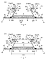
- FIG. 6 (a) is a view corresponding to FIG. 2 of another embodiment of the absorbent article of the present invention
- FIG. 6 (b) is a cross-sectional view (FIG. 6) of the absorbent article shown in FIG. 6 (a) in a natural state. 4 equivalent figure).
- FIG. 7 (a) is a view corresponding to FIG. 2 of still another embodiment of the absorbent article of the present invention
- FIG. 7 (b) is a cross-sectional view of the absorbent article shown in FIG. 7 (a) in a natural state.
- FIG. 4 is a diagram (corresponding to FIG. 4).
- FIG. 8 (a) is a view corresponding to FIG. 2 of still another embodiment of the absorbent article of the present invention
- FIG. 8 (b) is a cross-sectional view of the absorbent article shown in FIG. 8 (a) in a natural state.
- FIG. 4 is a diagram (corresponding to FIG. 4).
- the conventional absorbent article equipped with a leak-proof cuff had room for improvement in terms of the leak-proof performance of the leak-proof cuff.
- the present invention relates to an absorbent article that is excellent in leak-preventing performance of a leak-proof cuff and can effectively prevent lateral leakage.
- the diaper 1 has a vertical direction X corresponding to the front-back direction of the wearer, that is, a direction extending from the ventral side to the dorsal side via the crotch portion, and a lateral direction Y orthogonal to the vertical direction X, and includes the absorber 23. It includes an absorbent main body 2 and a pair of leak-proof cuffs 3 and 3 extending in the vertical direction X arranged by providing a separating portion 39 on a skin-facing surface of the absorbent main body 2.
- the "skin facing surface” is a surface of the absorbent article or its constituent members (for example, an absorbent body) that is directed toward the skin side of the wearer when the absorbent article is worn, that is, relatively of the wearer.
- the side closer to the skin, the “non-skin facing surface” is the surface of the absorbent article or its constituents that faces the opposite side of the skin when the absorbent article is worn, that is, relatively from the wearer's skin.
- the distant side is the term "when worn” as used herein means a state in which the normal proper wearing position, that is, the correct wearing position of the absorbent article is maintained.
- the diaper 1 (absorbent body 2) of the present embodiment has a crotch portion M arranged in the crotch portion of the wearer at the time of wearing and a front portion of the crotch portion M in the vertical direction X, that is, the wearer. It has a ventral portion F arranged on the ventral side of the diaper and a dorsal portion R arranged on the back side of the inseam M in the longitudinal direction X, that is, on the dorsal side of the wearer.
- the inseam M includes an excretion portion facing portion (not shown) that is arranged to face the excretion portion such as the wearer's penis when worn.
- the absorbent body 2 includes an absorber 23, a front surface sheet 21 arranged on the skin-facing surface side of the absorber 23, and a back surface sheet 22 arranged on the non-skin-facing surface side of the absorber 23. , These are integrated by a known joining means such as an adhesive.
- the absorber 23 is interposed between the front surface sheet 21 and the back surface sheet 22, and has a liquid-retaining absorbent core 24 containing a water-absorbent material and an outer surface (skin facing surface and non-skin facing surface) of the absorbent core 24. It is configured to include a core wrap sheet 25 that covers the skin facing surface).
- the absorbent main body 2 of the present embodiment has a rectangular shape in a plan view, extends from the ventral side F to the dorsal side R in the vertical direction X, and the longitudinal direction thereof coincides with the vertical direction X.
- the front surface sheet 21, the back surface sheet 22, and the absorber 23 various types conventionally used for this type of absorbent article can be used without particular limitation.
- the surface sheet 21 for example, a liquid-permeable single-layer or multi-layered non-woven fabric or perforated film can be used.
- the back sheet 22 is a leak-proof sheet, that is, liquid impermeable (property that does not allow liquid to pass through at all) or liquid impermeability (property that does not allow liquid to pass through, although it cannot be said to be liquid impervious).
- a sheet having the above can be used, and for example, a moisture-permeable resin film or a laminate of a resin film and a non-woven fabric can be used.
- Examples of the absorbent core 24 constituting the absorbent body 23 include a fiber stack made by stacking water-absorbent materials such as wood pulp and a water-absorbent polymer, and a sheet-shaped absorbent structure containing the water-absorbent material. Can be used.
- a sheet having liquid permeability can be used, and for example, paper or non-woven fabric can be used.
- the diaper 1 of the present embodiment includes a pair of side flap portions 4 and 4 including members extending outward in the horizontal direction Y from both side edges 23S and 23S along the vertical direction X of the absorber 23. To do.
- the front surface sheet 21 covers the entire surface of the absorber 23 facing the skin
- the back surface sheet 22 covers the entire non-skin facing surface of the absorber 23.
- the 22 further extends outward in the lateral direction Y from the side edges 23S and 23S of the absorber 23, and constitutes the side flap portion 4 together with the leakage-proof cuff forming sheet 30 described later.
- the side flap portion 4 of the present embodiment is located in the non-arranged portion of the absorber 23, and includes the front surface sheet 21, the back surface sheet 22, and the leakage-proof cuff forming sheet 30.
- These plurality of members constituting the side flap portion 4 are joined to each other by known joining means such as an adhesive, a heat seal, and an ultrasonic seal.
- a leg cuff 41 is formed at a portion corresponding to the wearer's leg circumference in each of the pair of side flap portions 4 and 4.
- the leg cuff 41 is a part of the side flap portion 4, and includes at least a leak-proof cuff forming sheet 30 and a leg cuff forming elastic member 42 fixed to the sheet 30 in an extended state. Then, as shown in FIG. 2, the back sheet 22 is included.
- a plurality of (specifically, two) thread-like elastic members 42 extending in the vertical direction X are arranged side by side in the horizontal direction Y on each of the pair of leg cuffs 41, 41 (side flap portions 4, 4).
- Each elastic member 42 extends in the vertical direction X over at least the entire length of the crotch portion M in the vertical direction X.
- the leg cuff 41 typically has an elastic member 42 extended in the vertical direction X, and an adhesive or the like is applied to a sheet (a leak-proof cuff forming sheet 30 and a back surface sheet 22 in the present embodiment) constituting the leg cuff 41. It is manufactured by releasing the elastic member 42 from the stretched state after joining by the joining means of. When the diaper 1 is worn, the leg cuff 41 (side flap portion 4) contracts due to the contraction force of the elastic member 42, and can fit around the wearer's legs.
- elastic members 11 for forming gathers around the waist which are arranged so as to be expandable and contractible in the lateral direction Y, are arranged in the lateral direction Y. It extends laterally from the side flap portion 4 on one side to the side flap portion 4 on the other side.
- the diaper 1 is a so-called deployable disposable diaper, and has a fastening structure 5 used when worn.
- the fastening structure 5 is formed by a pair of fastening tapes 51, 51 arranged on both side edges of the dorsal portion R of the diaper 1 along the vertical direction X, and a ventral portion F of the diaper 1. It is configured to include a target region 53 arranged on a non-skin facing surface (non-skin facing surface of the back sheet 22).
- the fastening tape 51 is provided with a fastening portion 52, and when the diaper 1 is worn, the fastening portion 52 is fastened to the target area 53. In the target area 53, the fastening portion 52 can be detachably fastened.
- the fastening portion 52 is made up of a male member of the mechanical hook-and-loop fastener
- the target region 53 is made up of a female member of the mechanical hook-and-loop fastener.
- each of the pair of leak-proof cuffs 3 and 3 is configured to include a leak-proof cuff forming sheet 30, and the base end portion where the sheet 30 is fixed to another member. 31 and an upright portion 32 in which the seat 30 stands up on the wearer side with the base end portion 31 as a starting point are provided in the lateral direction Y.
- a pair of leak-proof cuff forming sheets 30 are arranged on both sides of the absorbent main body 2 on the skin-facing surface facing the skin along the vertical direction X, and the pair of leak-proof cuff forming sheets 30 are arranged.
- a separating portion 39 is provided between the sheets 30 and 30. The separating portion 39 is located at the center of the absorbent main body 2 (diaper 1) in the lateral direction Y.
- Each leakage-proof cuff forming sheet 30 is arranged so as to straddle the side edge 23S of the absorber 23 in the lateral direction Y, and has a portion overlapping the absorber 23 in a plan view and a portion outside the absorber 23 in the lateral direction Y. It has a portion located in the lateral direction Y in the lateral direction.
- a hydrophobic sheet material is used from the viewpoint of surely fulfilling the role of preventing the leakage of body fluid such as urine to the outside.
- the hydrophobic sheet material for example, as the hydrophobic non-woven fabric, air-through non-woven fabric, spunbonded non-woven fabric, SMS non-woven fabric, SMMS non-woven fabric, SSMS non-woven fabric and the like can be used.
- a hydrophobic resin film and the resin thereof can be used.
- a laminate of the film and the non-woven fabric or the like can be used.
- S means a spunbonded non-woven fabric
- M means a melt-blown non-woven fabric.
- the base end portion 31 is a portion that serves as a standing starting point when the standing portion 32 stands up toward the wearer's skin side when the diaper 1 is worn. More specifically, the base end portion 31 is a portion of the leak-proof cuff forming sheet 30 fixed to the “other member”, which is adjacent to the upright portion 32 in the lateral direction Y, in other words, said. This is the innermost portion of the fixed portion in the lateral direction Y. Further, the "other member” is a member other than the leak-proof cuff forming sheet 30 among the constituent members of the diaper 1, and typically, the sheet 30 is placed on the non-skin facing surface side of the sheet 30. It is a member arranged so as to be in contact with each other, and in the present embodiment, it is a surface sheet 21 as shown in FIG.
- the base end portion 31 is a fixing portion between the leak-proof cuff forming sheet 30 and other members, and is typically provided by an adhesive such as hot melt or a known joining means such as heat fusion. It is formed.
- the base end portion 31 of the present embodiment has a linear shape in a plan view, extends in the vertical direction X over substantially the entire length of the leak-proof cuff forming sheet 30 in the vertical direction X, and also extends in the vertical direction X.
- the absorber 23 is located outside the side edge 23S in the lateral direction and in the vicinity of the side edge 23S.
- the plan view shape of the base end portion 31 is not particularly limited, and may be, for example, a wavy line, a curved line, a zigzag line, or the like in addition to a straight line, and the base end portion 31 is not continuous in one direction (longitudinal direction X). It may be a break line having a structure in which fixed portions and non-fixed portions of the leak-proof cuff forming sheet 30 and other members are alternately arranged in the vertical direction X.
- the upright portion 32 is a non-fixed portion of the leak-proof cuff forming sheet 30 with other members. As shown in FIG. 2, the leak-proof cuff forming sheet 30 constituting the upright portion 32 is bent by the bent portion 30F extending in the vertical direction X.
- the upright portion 32 is divided into a first portion 33 extending from the bent portion 30F to the side edge 30S along the vertical direction X of the sheet 30 and a second portion 34 extending from the bent portion 30F to the base end portion 31 and facing each other.
- the first portion 33 and the second portion 34 have a sheet overlapping portion 36 joined via the joint portion 35.
- the side edge 30S of the leak-proof cuff forming sheet 30 included in the first portion 33 is one of the side edges of the sheet 30 along the vertical direction X, which is relatively close to the center of the lateral direction Y of the diaper 1 (horizontal). The one on the inner side of the direction Y). Of the side edges of the leak-proof cuff forming sheet 30 along the vertical direction X, those relatively far from the center of the horizontal direction Y of the diaper 1 (those on the outer side of the horizontal direction Y) are diapers.
- a side edge portion 1S (see FIG. 1) is formed along the vertical direction X of 1.
- the bent portion 30F has a linear shape extending in the vertical direction X in the unfolded and extended state of the diaper 1 as shown in FIG.
- the sheet overlapping portion 36 has a two-layer structure due to two leak-proof cuff forming sheets 30 arranged so as to face each other.
- the "expanded and stretched state" of the diaper 1 means that the diaper 1 is in the unfolded state as shown in FIG. (Same as the dimensions when expanded in a plane with the influence of the elastic member completely removed).
- the upright portion 32 In the unfolded and extended state of the diaper 1, the upright portion 32 normally falls down without standing up, but in FIG. 2, which shows the same state, the upright portion 32 is upright from the viewpoint of easy explanation.
- the first portion 33 and the second portion 34 are joined at a joint portion 35 closer to the bent portion 30F than the side edge 30S of the leak-proof cuff forming sheet 30. ing.
- the joint portion 35 extends in the vertical direction X.
- extension not only when the joint portion 35 extends continuously in the vertical direction X, but also as shown in FIG. 5, a plurality of joint portions 35 are intermittently arranged in the vertical direction X. , The case where the plurality of joints 35 extend in the vertical direction X as a whole is included (details of the form of FIG. 5 will be described later).
- first portion 33 and the second portion 34 may be joined by an adhesive, or may be joined by fusing a forming material such as a fiber constituting both parts 33 and 34. ..
- the fusion of the first portion 33 and the second portion 34 can be carried out by using a known fusion means such as a heat seal or an ultrasonic seal.
- a plurality of (four in the present embodiment) elastic members 37 for forming leak-proof cuffs extending in the vertical direction X are arranged side by side in the horizontal direction Y in a state of being expandable and contractible in the vertical direction X.
- the sheet overlapping portion 36 has elasticity in the vertical direction X.
- the elastic member 37 for forming the leak-proof cuff is preferably thread-shaped, but may be strip-shaped instead. Further, in the present embodiment, a plurality of elastic members 37 for forming a leak-proof cuff are arranged in each sheet overlapping portion 36, but the number of the elastic members 37 is not particularly limited and may be one.
- the second portion 34 (the portion extending from the bent portion 30F to the base end portion 31 in the standing portion 32) is a bent portion 34F extending in the vertical direction X in the horizontal direction Y. It is bent outward, and the sheet overlapping portion 36 extends outward in the lateral direction Y from the bent portion 34F.
- the leak-proof cuff 3 is typically produced by fixing the leak-proof cuff-forming elastic member 37 to the leak-proof cuff-forming sheet 30 in an stretched state and then releasing the stretched state. Due to such a manufacturing method, a large number of wrinkles are formed on the surface of the sheet overlapping portion 36 which can come into contact with the skin of the wearer of the diaper 1, more specifically, on the surfaces of the first portion 33 and the second portion 34, respectively. Exists. The wrinkles on the surface of the sheet overlapping portion 36 are arranged substantially regularly in the vertical direction X.
- the standing portion 32 is present at least in the inseam M. This is because the part of the diaper 1 where excrement is concentrated and lateral leakage is particularly problematic is the inseam M. As shown in FIG. 1, the standing portion 32 of the present embodiment extends over the entire length of the crotch portion M in the longitudinal direction X, and further extends to both the ventral side portion F and the dorsal side portion R.
- standing inhibition portions 38 are formed on both outer sides of the standing portions 32 of each of the pair of leak-proof cuffs 3 and 3 in the vertical direction X.
- the standing portion 32 is sandwiched between the standing blocking portion 38 on one end side (ventral side F side) and the standing blocking portion 38 on the other end side (dorsal side R side) in the longitudinal direction X.
- a portion of the leak-proof cuff forming sheet 30 that exists at the same position as the standing portion 32 (that is, a non-fixed portion with another member) in the lateral direction Y overlaps with the absorber 23 in a plan view. Is fixed to another member (the surface sheet 21 in the present embodiment), so that the standing portion 38 does not stand even if the standing portion 32 stands up.
- the standing portions 32 of each of the pair of leak-proof cuffs 3 and 3 raise the base end portion 31 by the contraction force of the elastic member 37 for forming the leak-proof cuff arranged in the sheet overlapping portion 36.
- a pair of leak-proof walls composed of the upright portions 32 are formed on both sides of the absorbent body 2 at least in the inseam M along the vertical direction X of the skin-facing surface.
- This pair of leak-proof walls blocks excrement such as urine and feces excreted on the skin-facing surface of the diaper 1 and prevents the excrement from leaking to the outside of the diaper 1 in the lateral direction Y, so-called lateral leakage. To do.
- the central portion (the portion including the inseam M) of the diaper 1 which is the arrangement portion of the elastic member 37 is not formed due to the contraction force of the elastic member 37 for forming the leak-proof cuff.
- the diaper 1 is curved so as to be convex on the skin-facing surface side (back surface sheet 22 side), in other words, concave on the skin-facing surface side (front surface sheet 21 side). In this way, the diaper 1 is transformed into a boat shape as a whole. Since such a boat-shaped diaper 1 easily follows the shape of the crotch portion of the wearer, the seat overlapping portion 36 of the upright portion 32 in the upright state of the diaper 1 fits well on the wearer's skin and adheres thereto. Therefore, the lateral leakage prevention function of the leakage prevention cuff 3 can be effectively exhibited.
- the first portion 33 of the upright portion 32 that is, the portion extending from the bent portion 30F in the upright portion 32 to the side edge 30S of the leakage-proof cuff forming sheet 30
- the sheet 30 has a free edge portion 330, which is a portion extending from the joint portion 35 in a non-fixed state to another member.
- the free edge portion 330 of the first portion 33 extends in the vertical direction X over the entire length of the vertical direction X of the standing portion 32.
- the free edge portion 330 of the first portion 33 is at least in the natural state of the diaper 1 as shown in FIG. 3, as shown in FIG. 4, the stretchable portion 360 (the bent portion 30F in the first portion 33) starts from the joint portion 35.
- the pocket structure 3P is formed between the warped free edge portion 330 and the telescopic portion 360. Since the state of the diaper 1 when worn is close to the natural state, such a pocket structure 3P extends in the vertical direction X along the standing portion 32 in the standing state when the diaper 1 is worn.
- the "natural state" of the diaper 1 is a state in which no external force is applied to the diaper 1 (relaxed state), and more specifically, the diaper 1 has elasticity in the vertical direction X.
- This is the state when the expansion amount of the expansion / contraction portion 360 of the leakage cuff 3 (the arrangement portion of the elastic member 37 for forming the leakage prevention cuff fixed in the extension state) is 0 (zero).
- the amount of expansion of the expansion / contraction portion 360 is 0 means that all of the elastic members 37 for forming the leak-proof cuff existing in the expansion / contraction portion 360 are not elongated, and the length of the expansion / contraction portion 360 in the vertical direction X. Is the shortest state.
- the first portion 33 is located inside the second portion 34 in the lateral direction Y.
- the first portion 33 is relatively close to the center of the lateral Y of the diaper 1
- the second portion 34 is relatively far from the center of the lateral Y of the diaper 1.
- the pocket structure 3P formed by the warp of the free edge portion 330 of the first portion 33 is as shown in FIG. It exists inward in the lateral direction Y with respect to the leakage-proof cuff 3 (standing portion 32), that is, exists in a region sandwiched between the pair of leakage-proof cuffs 3, 3.
- Such a pocket structure 3P formed inside the leak-proof cuff 3 serves as a barrier for excrement that tries to get over the leak-proof cuff 3, and can prevent the inconvenience that the excrement gets over the leak-proof cuff 3 in advance. ..
- the free edge portion 330 of the first portion 33 extends from the joint portion 35 between the first portion 33 and the second portion 34 constituting the sheet overlapping portion 36 in a non-fixed state to other members.
- the extension length L1 (see FIG. 2) of the free edge portion 330 of the first portion 33 from the joint portion 35 is the length L2 (see FIG. 2) extending from the joint portion 35 to the base end portion 31 in the second portion 34. It is required to be 0.05 times or more.
- the lengths L1 and L2 are the design dimensions (the same as the dimensions when the sheet (leakage-proof cuff forming sheet 30) forming the relevant portion is extended and expanded in a plane with the influence of the elastic member completely eliminated). It is the length in the expanded state until it becomes. If L1 / L2 is less than 0.05 times, the free edge portion 330 is too short with respect to the length L2 related to the standing height of the standing portion 32. The effect of the pocket structure 3P is not sufficiently obtained, and the effect of improving the leakage prevention performance of the leakage prevention cuff 3 is not sufficiently obtained.
- L1 / L2 is preferably 0.1 times or more, more preferably 0.15 times or more, still more preferably 0.15 times or more. It is 0.2 times or more.
- the upper limit of L1 / L2 is not particularly limited, but is preferably 0.9 times or less, more preferably 0.8 times or less, and further, from the viewpoint of exerting the function of the free edge portion 330 as a pocket structure. It is preferably 0.7 times or less.
- the extension length L1 (see FIG. 2) of the free edge portion 330 of the first portion 33 from the joint portion 35 is preferably 2 mm or more, more preferably 4 mm or more, and preferably 25 mm or less, more preferably 20 mm or less. Is.
- the length L2 from the joint portion 35 to the base end portion 31 in the second portion 34 is preferably 5 mm or more, more preferably 10 mm or more, and preferably 30 mm or less, more preferably 25 mm or less.
- the base end portion 31 of one of the leak-proof cuffs 3 The separation distance between one and the other (shortest separation distance) is W1, the separation distance between the free edge 330 of one leak-proof cuff forming sheet 30 and that of the other (shortest separation distance) is W2, and one sheet overlaps.
- W3 the separation distance between the portion 36 and the other portion is W3
- W2 ⁇ W1 and W2 ⁇ W3 are established in the natural state of the diaper 1 as shown in FIG. With the establishment of such a magnitude relationship, the pocket structure 3P can sufficiently function as a barrier for excrement that tries to get over the leak-proof cuff 3 when the diaper 1 is worn.
- the ratio of the separation distance W1 to the separation distance W2 is preferably 1.01 or more, more preferably 1.05 or more, and preferably 2.0 or less, more preferably 1.01 or more, more preferably 1.05 or more, and more preferably 2.0 or less as the former / latter, assuming the former> the latter. Is 1.5 or less.
- the ratio of the separation distance W3 to the separation distance W2 is preferably 1.01 or more, more preferably 1.05 or more, and preferably 1.9 or less, more preferably 1.01 or more, more preferably 1.05 or more, and more preferably 1.9 or less as the former / latter, assuming the former> the latter. Is 1.4 or less.
- the separation distance W1 is preferably 115 mm or more, more preferably 120 mm or more, and preferably 145 mm or less, more preferably 140 mm or less.
- the separation distance W2 is preferably 75 mm or more, more preferably 80 mm or more, and preferably 135 mm or less, more preferably 130 mm or less.
- the separation distance W3 is preferably 100 mm or more, more preferably 105 mm or more, and preferably 140 mm or less, more preferably 135 mm or less.
- a plurality of (four in the present embodiment) elastic members for forming a leak-proof cuff extending in the vertical direction X between the first portion 33 and the second portion 34.
- the diapers 1 are arranged side by side in the horizontal direction Y in a state where the 37s can be expanded and contracted in the vertical direction X, they are located at the innermost side of the plurality of elastic members 37 in the horizontal direction Y when the diaper 1 is worn.
- the thing (the one indicated by the reference numeral 37a in the figure) has a larger stress than the one located at the outermost side in the lateral direction Y (the one indicated by the reference numeral 37b in the figure).
- the diaper 1 when the diaper 1 is worn, the magnitude relationship of "stress of the innermost elastic member 37a in the lateral direction> stress of the outermost elastic member 37b in the lateral direction" is established, so that the diaper extends from the joint portion 35.
- the free edge portion 330 of the first portion 33 is likely to warp, and the pocket structure 3P is likely to be formed.
- the above-mentioned "when wearing diaper 1 (absorbent article)" is a state in which the "length of the cuff in the vertical direction" is in the range of 30 or more and 90 or less.
- the “longitudinal length of the cuff” referred to here is based on the vertical length of the leak-proof cuff (the leak-proof cuff 3 in the diaper 1) provided in the absorbent article in the maximum extended state. Is the relative vertical length of.
- the vertical length of the cuff is typically the shortest when the leak-proof cuff is in its natural state (no external force is applied), but it is not zero.
- the ratio of the stress of the elastic member 37a on the innermost side in the lateral direction to the stress on the elastic member 37b on the outermost side in the lateral direction when the diaper 1 is worn is preferably 1 as the former / the latter on the premise that the former> the latter. It is 0.01 or more, more preferably 1.05 or more, and preferably 3 or less, more preferably 2 or less.
- the stress of the innermost elastic member 37a in the lateral direction when the diaper 1 is worn is preferably 0.03 N or more, more preferably 0.06 N or more, and preferably 0.24 N or less, more preferably 0.2 N. It is as follows.
- the stress of the outermost elastic member 37b in the lateral direction when the diaper 1 is worn is preferably 0.02 N or more, more preferably 0.05 N or more, and preferably 0.2 N or less, more preferably 0.16 N. It is as follows.
- the stress of the elastic member including the leak-proof cuff forming elastic member 37 is measured by the following method.
- the elastic member for forming a leak-proof cuff to be measured (the elastic member 37a located on the innermost side in the lateral direction Y and the elastic member 37b located on the outermost side in the lateral direction Y). Cut out and use as a measurement sample.
- the length of the measurement sample in the longitudinal direction (length in the longitudinal direction X) is 100 mm.
- the measurement sample is sandwiched between the chucks of the Tencilon universal testing machine (RTC-1210A) manufactured by ORIENTEC Co., Ltd., and the distance between the chucks is widened at a speed of 300 mm / min to extend the measurement sample in the longitudinal direction (longitudinal direction).
- the distance between the chucks is narrowed at a speed of 300 mm / min to shrink the measurement sample to a predetermined length, and the stress (shrinking stress) at that time (unit:: N) is measured.
- the stress is clear from the above definition of "when the diaper 1 (absorbent article) is worn".
- the vertical length of the cuff in the maximum extension state of the measurement sample is 100
- the contraction stress is such that the vertical length of the cuff is 30 or more and 90 or less. Therefore, in this measurement, the measurement sample is used.
- the maximum extension state corresponding to the cuff vertical length 100 is contracted to the length corresponding to the cuff vertical length 30.
- the thickness of the elastic member 37a on the innermost side in the lateral direction is set to the elastic member on the outermost side in the lateral direction. There is a method of making it larger than that of 37b.
- first portion side fusion area the area of the joint portion 35 when the joint portion 35 is observed from the second portion 34 side.
- FIG. 5 shows an example of a form in which the first partial side fusion area and the second partial side fusion area are different.
- FIG. 5 shows a case where the joint portion 35 (fused portion) of one of the pair of leakage-proof cuffs 3 and 3 in the diaper 1 is observed along the extending direction (longitudinal direction X).
- FIG. 5 (a) when the joint portion 35 is observed from the outside of the lateral direction Y (the side relatively far from the center of the lateral direction Y of the diaper 1), FIG. 5 (b) shows the joint portion 35 beside the joint portion 35. This is a case of observing from the inside of the direction Y (the side relatively close to the center of the lateral direction Y of the diaper 1).
- FIG. 5A shows the joint portion 35 on the second portion 34 side (horizontal direction Y). It is a case where the joint portion 35 is observed along the vertical direction X from the outside), and FIG. 5B is a case where the joint portion 35 is observed from the first portion 33 side (inside the horizontal direction Y) along the vertical direction X. ..
- a plurality of joint portions 35 are intermittently arranged in the vertical direction X in both the observation from the first portion 33 side and the observation from the second portion 34 side.
- the area (fused area) of each joint 35 is larger when observed from the second portion 34 side than when observed from the first portion 33, and is leak-proof cuff 3 (for leak-proof cuff formation).
- the unit area of the sheet 30 specifically, for example, a rectangular area in a plan view having a length of 10 mm in both the vertical direction X and the horizontal direction Y (corresponding to the "measurement piece” in the method for measuring the fusion area described later). In the region), the magnitude relationship of "first partial side fusion area ⁇ second partial side fusion area" is established.
- the fused area (joint area) is measured by the following method.
- a leak-proof cuff 3 (leak-proof cuff forming sheet 30) is cut out from the diaper 1, and a 10 mm ⁇ 10 mm rectangular shape in a plan view including the joint portion 35 (fused portion) is cut out from the cut-out leak-proof cuff 3 and measured.
- the fusion area is measured from the contour of the joint portion 35 using, for example, VHX-1000 manufactured by KEYENCE as an image analysis device. To do.
- the warp of the free edge portion 330 of the first portion 33 can be promoted.
- the "first portion” is contrary to the form shown in FIG.
- the warp of the free edge portion 330 of the first portion 33 can be promoted.
- the difference between the first partial side fusion area and the second partial side fusion area means that when the joint portion 35 (fused portion) is formed, the first portion 33 side and the second portion are to be formed with respect to the planned formation portion. It can be carried out by performing the welding process from both sides of the portion 34, or can be carried out by performing the fusion process from only one of the first portion 33 side and the second portion 34 side.
- Known fusion means such as heat seal and ultrasonic seal can be used for the fusion process.
- fusion processing is performed from only one of the first portion 33 side and the second portion 34 side to make the first portion side fusion area and the second portion side fusion area different, as a fusion means. It is preferable to use a fusion means using ultrasonic waves such as an ultrasonic seal.
- FIG. 6 to 8 show other embodiments of the absorbent article of the present invention.
- the embodiments described later will mainly be described with components different from those of the diaper 1 described above, and similar components will be designated by the same reference numerals and description thereof will be omitted.
- the description of the diaper 1 is appropriately applied to the components not particularly described.
- the second portion 34 of the standing portion 32 was bent outward in the lateral direction Y (see FIGS. 2 and 4), but in the diaper 1A shown in FIG. 6, the second portion 34 was bent.
- the entire standing portion 32 extends in one direction (from the outer side to the inner side in the lateral direction Y) from the base end portion 31.
- two elastic members 37 for forming a leak-proof cuff are arranged in each of the pair of sheet overlapping portions 36, 36, and the number of the elastic members 37 arranged in each of the sheet overlapping portions 36 is larger than that of the diaper 1. Few.
- the diaper 1A is configured in the same manner as the diaper 1 except for the above points, and W2 ⁇ W1 and W2 ⁇ W3 are established in the natural state.
- Diaper 1A has basically the same effect as diaper 1, but from the viewpoint of surely preventing the inconvenience of excrement overcoming the leak-proof cuff 3, the second part 34 is bent like diaper 1. It is preferable that the portion 34F is bent outward in the lateral direction Y.
- the first portion 33 is located outside the second portion 34 in the lateral direction Y, and the arrangement of both portions 34A and 34B is opposite to that of the diapers 1 and 1A.
- the first portion 33 is relatively far from the center of the lateral direction Y of the diaper 1, and the second portion 34 is relatively close to the center of the lateral direction Y of the diaper 1. Therefore, as shown in FIG. 7B, the pocket structure 3P formed by the warp of the free edge portion 330 of the first portion 33 is outward in the lateral direction Y with respect to the leakage-proof cuff 3 (standing portion 32).
- the pocket structure 3P formed on the outside of the leak-proof cuff 3 captures the excrement that has passed over the leak-proof cuff 3, and the excrement moves outward in the lateral direction Y from the pocket structure 3P. It is possible to prevent lateral leakage.
- the free edge portion 330 of the first portion 33 extends from the joint portion 35 between the first portion 33 and the second portion 34 constituting the sheet overlapping portion 36 in a non-fixed state to other members.
- the base end portion 31 of one of the leak-proof cuffs 3 The separation distance between and the other is W1, the separation distance between the free edge 330 of one leak-proof cuff forming sheet 30 and that of the other is W2, and the separation distance between one sheet overlapping portion 36 and that of the other (the shortest).
- W3 it is preferable that W2> W1 and W2> W3 are satisfied in the natural state of the diaper as shown in FIG. With the establishment of such a magnitude relationship, the pocket structure 3P can sufficiently function as a pocket for catching excrement that has passed over the leak-proof cuff 3 when the diaper 1 is worn.
- the ratio of the separation distance W1 to the separation distance W2 is preferably 0.6 or more, more preferably 0.65 or more, and preferably 0.99 or less, more preferably 0.6 or more, more preferably 0.65 or more, and more preferably 0.99 or less as the former / latter, assuming the former ⁇ the latter. Is less than or equal to 0.95.
- the ratio of the separation distance W3 to the separation distance W2 is preferably 0.55 or more, more preferably 0.6 or more, and preferably 0.95 or less, more preferably 0.55 or more, more preferably 0.6 or more, and more preferably 0.95 or less as the former / latter, assuming the former ⁇ the latter. Is less than or equal to 0.9.
- the separation distance W1 is preferably 115 mm or more, more preferably 120 mm or more, and preferably 145 mm or less, more preferably 140 mm or less.
- the separation distance W2 is preferably 120 mm or more, more preferably 125 mm or more, and preferably 180 mm or less, more preferably 175 mm or less.
- the separation distance W3 is preferably 100 mm or more, more preferably 105 mm or more, and preferably 140 mm or less, more preferably 135 mm or less.
- the second portion 34 of the upright portion 32 was bent outward in the lateral direction Y at the bent portion 34F (see FIG. 7), but in the diaper 1C shown in FIG. 8, the second portion 34 is bent.
- the entire upright portion 32 extends from the base end portion 31 in one direction (the direction from the outside to the inside in the lateral direction Y).
- two elastic members 37 for forming a leak-proof cuff are arranged in each of the pair of sheet overlapping portions 36, 36, and the number of the elastic members 37 arranged in each of the sheet overlapping portions 36 is larger than that in the diaper 1B. Few.
- the diaper 1C is configured in the same manner as the diaper 1B except for the above points, and W2> W1 and W2> W3 are established in the natural state.
- the diaper 1C has the same effect as the diaper 1B.
- the absorbable article of the present invention broadly includes articles used for absorbing body fluids (urine, menstrual blood, loose stool, sweat, etc.) discharged from the human body, and other than the deployable disposable diaper as in the above embodiment, for example, It may include pants-type disposable diapers, urine absorbing pads, sanitary napkins, sanitary shorts, and the like. The following additional notes are further disclosed with respect to the embodiments of the present invention.
- ⁇ 1> It has a vertical direction corresponding to the front-back direction of the wearer and a horizontal direction orthogonal to the vertical direction, and is arranged so as to provide a separation portion between an absorbent body having an absorber and a skin-facing surface of the absorbent body.
- An absorbent article comprising a pair of leak-proof cuffs extending in the vertical direction.
- Each of the pair of leak-proof cuffs is configured to include a leak-proof cuff forming sheet, and the leakage-proof cuff forming sheet is fixed to another member at a base end portion and the base end portion as a starting point.
- the leak-proof cuff forming sheet has an upright portion that stands up on the wearer side.
- the leak-proof cuff forming sheet constituting the upright portion is bent at the bent portion extending in the vertical direction.
- the upright portion is divided into a first portion extending from the bent portion to the side edge of the leak-proof cuff forming sheet along the vertical direction and a second portion extending from the bent portion to the base end portion, and facing each other. It has a sheet overlapping portion in which the first portion and the second portion are joined via a joint portion.
- the first portion has a free edge portion, which is a portion of the leak-proof cuff forming sheet extending from the joint portion in a non-fixed state to another member.
- the extension length L1 of the free edge portion from the joint portion is 0.1 times or more and 0.9 times or less, preferably 0.
- ⁇ 4> The absorbency according to any one of ⁇ 1> to ⁇ 3>, wherein the length L2 from the joint portion to the base end portion in the second portion is 5 mm or more and 30 mm or less, preferably 10 mm or more and 25 mm or less. Goods.
- ⁇ 8> The absorbent article according to ⁇ 6> or ⁇ 7>, wherein the ratio of W3 to W2 (W3 / W2) is 1.01 or more and 1.9 or less, preferably 1.05 or more and 1.4 or less. ..
- W1 and W2> W3 are established in the natural state of the absorbent article, where the separation distance of the leak cuff from the sheet overlapping portion is W3.
- W1 / W2 is 0.6 or more and 0.99 or less, preferably 0.65 or more and 0.95 or less.
- the ratio of W3 to W2 (W3 / W2) is 0.55 or more and 0.95 or less, preferably 0.6 or more and 0.9 or less. ..
- a plurality of elastic members for forming a leak-proof cuff are arranged side by side in the lateral direction between the first portion and the second portion.
- the innermost elastic member located on the innermost side in the lateral direction is the outermost elastic member located on the outermost side in the lateral direction among the plurality of elastic members for forming a leak-proof cuff.
- ⁇ 14> The absorbent article according to ⁇ 13>, wherein the ratio of the stress of the innermost elastic member to the stress of the outermost elastic member is 1.01 or more and 3 or less, preferably 1.05 or more and 2 or less.
- the joint portion is a fusion portion in which the first portion and the second portion are fused, and the area of the fusion portion when the fusion portion is observed from the first portion side and the fusion portion.
- Examples 1 and 2 Comparative Example 1
- a deployable disposable diaper having the same basic configuration as the diaper 1 shown in FIG. 1, that is, an absorbent article in which the first portion is located laterally inward from the second portion in the upright portion of the leak-proof cuff was produced.
- a deployable disposable diaper we prepared a Mary's tape type S size (made in 2017, registered trademark) manufactured by Kao Corporation, and adjusted the dimensions of each part of the leak-proof cuff of the prepared diaper as appropriate.
- the deployable disposable diapers of Examples and Comparative Examples were prepared.
- Examples 3 to 4, Comparative Example 2 A deployable disposable diaper having the same basic configuration as the diaper 1B shown in FIG. 7, that is, an absorbent article in which the first portion is located laterally outward from the second portion in the upright portion of the leak-proof cuff was produced.
- a deployable disposable diaper we prepared a Mary's tape type S size (made in 2017, registered trademark) manufactured by Kao Corporation, and adjusted the dimensions of each part of the leak-proof cuff of the prepared diaper as appropriate.
- the deployable disposable diapers of Examples and Comparative Examples were prepared.
- the model doll provided with the excretion point was put on the diaper to be evaluated, and the lateral leakage prevention property of the leakage-proof cuff of the diaper was evaluated by the following method. First, the diaper was attached to the model doll, and the model doll was tilted 90 ° so as to be turned sideways. In this state, 10 g of pseudo loose stool was injected into the site corresponding to the excretion point in the diaper.
- the composition of the pseudo loose stool is 22.5% by mass of bentonite, 0.5% by mass of a surfactant (poise 530, solid content 40% by mass, manufactured by Kao Co., Ltd.), and an aqueous solution of Emargen 130K 0.03% by mass (manufactured by Kao Co., Ltd.). 1.5% by mass, ion-exchanged water 75.5% by mass, viscosity 40 mPa ⁇ s (23 ° C, vibration viscometer: manufactured by A & D Co., Ltd., SV-10), surface tension 55 mN / It was m.
- the model doll Immediately after injecting the pseudo loose stool, the model doll is placed upright, and when the diaper located in the inseam of the model doll is pressed against the model doll with a pressure of 3 kPa, the pseudo loose stool laterally outwards from the leak-proof cuff of the diaper. It was observed whether or not it leaked.
- the above operation was performed 10 times for each evaluation target, and the probability that lateral leakage could be prevented (the ratio of the number of times that pseudo loose stool leakage was not observed to the total of 10 times) was defined as lateral leakage prevention. The larger this value is, the better the lateral leakage prevention property of the leakage prevention cuff is, and the higher the evaluation is.
- an absorbent article which is excellent in the leakage prevention performance of the leakage prevention cuff and can effectively prevent lateral leakage.
Landscapes
- Health & Medical Sciences (AREA)
- Epidemiology (AREA)
- Engineering & Computer Science (AREA)
- Biomedical Technology (AREA)
- Heart & Thoracic Surgery (AREA)
- Vascular Medicine (AREA)
- Life Sciences & Earth Sciences (AREA)
- Animal Behavior & Ethology (AREA)
- General Health & Medical Sciences (AREA)
- Public Health (AREA)
- Veterinary Medicine (AREA)
- Absorbent Articles And Supports Therefor (AREA)
Abstract
一対の防漏カフ(3,3)それぞれは、防漏カフ形成用シート(30)を含んで構成され、基端部(31)と起立部(32)とを有する。起立部(32)は、シート(30)の折り曲げ部(30F)から該シート(30)の縦方向(X)に沿う側縁(30S)にわたる第1部分(33)と、折り曲げ部(30F)から基端部(31)にわたる第2部分(34)とに区分され、且つ相対向する両部分(33,34)が接合部(35)を介して接合されたシート重なり部(36)を有する。第1部分(33)は、シート(30)が接合部(35)から他の部材に非固定の状態で延出した部分である、自由縁部(330)を有する。自由縁部(330)の接合部(35)からの延出長さ(L1)が、第2部分(34)における接合部(35)から基端部(31)にわたる長さ(L2)の0.05倍以上である。
Description
本発明は、着用者の肌側に向かって起立する防漏カフを備えた吸収性物品に関する。
使い捨ておむつなどの吸収性物品において、防漏カフ、立体ギャザー、立体ガードなどとも呼ばれる横漏れ防止部材を具備するものが知られている。この横漏れ防止部材は、典型的には、吸収性物品の本体の縦方向(着用者の前後方向に対応する方向)に沿う両側部に一対配され、横漏れ防止部材形成用シートと、該シートに伸長状態で固定された弾性部材とを具備し、該吸収性物品の着用時に着用者の肌側に起立し、便などの排泄物を堰き止めて横漏れを防止する。
特許文献1及び2には、横漏れ防止部材として、横漏れ防止部材形成用シートが他の部材に固定された基端部と、該基端部を起点として該シートが着用者側に起立する起立部とを有し、該起立部が、縦方向に延びる折り曲げ部にて折り曲げられ、該基端部から該折り曲げ部に向かって横方向(縦方向と直交する方向)内側へ延びる内側延出部と、該折り曲げ部から横方向外側へ延び、該内側延出部よりも着用者の肌に近い側に位置する外側延出部とを有するものが記載されている。特許文献3に記載の横漏れ防止部材は、着用者側に起立する起立部が、横方向に沿う断面視においてT字状をなしている。
本発明は、着用者の前後方向に対応する縦方向と該縦方向に直交する横方向とを有し、吸収体を具備する吸収性本体と、該吸収性本体の肌対向面に離間部を設けて配置された該縦方向に延びる一対の防漏カフとを具備する吸収性物品に関する。前記一対の防漏カフは、それぞれ、防漏カフ形成用シートを含んで構成され、且つ該防漏カフ形成用シートが他の部材に固定された基端部と、該基端部を起点として該防漏カフ形成用シートが着用者側に起立する起立部とを有している。前記起立部を構成する前記防漏カフ形成用シートは、前記縦方向に延びる折り曲げ部にて折り曲げられている。前記起立部は、前記折り曲げ部から前記防漏カフ形成用シートの前記縦方向に沿う側縁にわたる第1部分と、該折り曲げ部から前記基端部にわたる第2部分とに区分され、且つ相対向する該第1部分と該第2部分とが接合部を介して接合されたシート重なり部を有している。前記第1部分は、前記防漏カフ形成用シートが前記接合部から他の部材に非固定の状態で延出した部分である自由縁部を有している。前記自由縁部の前記接合部からの延出長さが、前記第2部分における該接合部から前記基端部にわたる長さの0.05倍以上である。
防漏カフを備えた従来の吸収性物品は、防漏カフの漏れ防止性能の点で改善の余地があった。本発明は、防漏カフの漏れ防止性能に優れ、横漏れを効果的に防止し得る吸収性物品に関する。
以下本発明を、その好ましい実施形態に基づき図面を参照しながら説明する。なお、以下の図面の記載において、同一又は類似の部分には、同一又は類似の符号を付している。図面は基本的に模式的なものであり、各寸法の比率などは現実のものとは異なる場合がある。
図1及び図2には、本発明の吸収性物品の一実施形態である使い捨ておむつ1が示されている。おむつ1は、着用者の前後方向、すなわち腹側から股間部を介して背側に延びる方向に対応する縦方向Xと、これに直交する横方向Yとを有し、吸収体23を具備する吸収性本体2と、該吸収性本体2の肌対向面に離間部39を設けて配置された縦方向Xに延びる一対の防漏カフ3,3とを具備する。
本明細書において、「肌対向面」は、吸収性物品又はその構成部材(例えば吸収性本体)における、吸収性物品の着用時に着用者の肌側に向けられる面、すなわち相対的に着用者の肌から近い側であり、「非肌対向面」は、吸収性物品又はその構成部材における、吸収性物品の着用時に肌側とは反対側に向けられる面、すなわち相対的に着用者の肌から遠い側である。なお、ここでいう「着用時」は、通常の適正な着用位置、すなわち当該吸収性物品の正しい着用位置が維持された状態を意味する。
本実施形態のおむつ1(吸収性本体2)は、図1に示すように、着用時に着用者の股間部に配される股下部Mと、該股下部Mより縦方向Xの前方すなわち着用者の腹側に配される腹側部Fと、該股下部Mより縦方向Xの後方すなわち着用者の背側に配される背側部Rとを有する。股下部Mは、着用時に着用者の陰茎等の排泄部に対向配置される排泄部対向部(不図示)を含む。
吸収性本体2は、吸収体23と、該吸収体23の肌対向面側に配された表面シート21と、該吸収体23の非肌対向面側に配された裏面シート22とを具備し、これらが接着剤等の公知の接合手段により一体化されて構成されている。吸収体23は、表面シート21と裏面シート22との間に介在配置されており、吸水性材料を含む液保持性の吸収性コア24と、該吸収性コア24の外面(肌対向面及び非肌対向面)を被覆するコアラップシート25とを含んで構成されている。本実施形態の吸収性本体2は平面視長方形形状を有し、腹側部Fから背側部Rにわたって縦方向Xに延在し、その長手方向が縦方向Xに一致している。
表面シート21、裏面シート22及び吸収体23としては、それぞれ、この種の吸収性物品に従来用いられている各種のものを特に制限なく用いることができる。表面シート21としては、例えば、液透過性を有する単層若しくは多層構造の不織布又は開孔フィルムを用いることができる。裏面シート22としては、防漏性を有するシート、すなわち、液不透過性(液を全く通さない性質)又は液難透過性(液不透過性とまでは言えないものの、液を通し難い性質)を有するシートを用いることができ、例えば、透湿性の樹脂フィルム、樹脂フィルムと不織布との積層体を用いることができる。吸収体23を構成する吸収性コア24としては、例えば、木材パルプや吸水性ポリマー等の吸水性材料を積繊してなる積繊体、該吸水性材料を含有するシート状の吸収構造体を用いることができる。吸収体23を構成するコアラップシート25としては、液透過性を有するシートを用いることができ、例えば、紙、不織布を用いることができる。
本実施形態のおむつ1は、吸収体23の縦方向Xに沿う両側縁23S,23Sから横方向Yの外方に延出する部材を含んで構成される一対のサイドフラップ部4,4を具備する。本実施形態では図2に示すように、表面シート21は吸収体23の肌対向面の全域を被覆し、裏面シート22は吸収体23の非肌対向面の全域を被覆し、両シート21,22は更に、吸収体23の両側縁23S,23Sから横方向Yの外方に延出し、後述する防漏カフ形成用シート30とともにサイドフラップ部4を構成している。このように、本実施形態のサイドフラップ部4は、吸収体23の非配置部に位置し、表面シート21、裏面シート22及び防漏カフ形成用シート30を含んで構成されている。サイドフラップ部4を構成するこれら複数の部材は、接着剤、ヒートシール、超音波シール等の公知の接合手段によって互いに接合されている。
一対のサイドフラップ部4,4それぞれにおける着用者の脚周りに対応する部位にはレッグカフ41が形成されている。レッグカフ41は、サイドフラップ部4の一部であり、少なくとも防漏カフ形成用シート30と、該シート30に伸長状態で固定されたレッグカフ形成用弾性部材42とを含んで構成され、本実施形態では更に図2に示すように、裏面シート22を含んで構成されている。本実施形態では一対のレッグカフ41,41(サイドフラップ部4,4)それぞれに、縦方向Xに延びる複数(具体的には2本)の糸状の弾性部材42が、横方向Yに並べて配置され、各該弾性部材42は、少なくとも股下部Mの縦方向Xの全長にわたって縦方向Xに延在している。レッグカフ41は、典型的には、弾性部材42を縦方向Xに伸長させた状態で、レッグカフ41を構成するシート(本実施形態では防漏カフ形成用シート30及び裏面シート22)に接着剤等の接合手段により接合した後、弾性部材42を伸長状態から解放することで作製される。おむつ1の着用時には、弾性部材42の収縮力によってレッグカフ41(サイドフラップ部4)が収縮し、着用者の脚周りにフィットし得る。
腹側部F及び背側部Rそれぞれの縦方向Xの端部すなわちウエスト端部には、横方向Yに伸縮可能な状態で配された胴周りギャザー形成用弾性部材11が、横方向Yの一方側のサイドフラップ部4から他方側のサイドフラップ部4にわたって横方向Yに延在している。斯かる構成によりおむつ1の着用時には、胴周りギャザー形成用弾性部材11の収縮力によって前記ウエスト端部が収縮し、着用者の腰周りにフィットし得る。
おむつ1は、いわゆる展開型使い捨ておむつであり、着用時に使用される止着構造5を具備する。止着構造5は、図1に示すように、おむつ1の背側部Rの縦方向Xに沿う両側縁部に配置された一対のファスニングテープ51,51と、おむつ1の腹側部Fの非肌対向面(裏面シート22の非肌対向面)に配置されたターゲット領域53とを含んで構成されている。ファスニングテープ51には止着部52が設けられており、おむつ1を着用する際には、止着部52をターゲット領域53に止着する。ターゲット領域53は、止着部52が着脱自在に止着可能になされている。典型的には、止着部52は機械的面ファスナーのオス部材からなり、ターゲット領域53は機械的面ファスナーのメス部材からなる。
おむつ1の主たる特徴部分である防漏カフ3について詳細に説明する。図1及び図2に示すように、一対の防漏カフ3,3は、それぞれ、防漏カフ形成用シート30を含んで構成され、且つ該シート30が他の部材に固定された基端部31と、該基端部31を起点として該シート30が着用者側に起立する起立部32とを横方向Yに有する。
防漏カフ形成用シート30は、図1及び図2に示すように、吸収性本体2の肌対向面における縦方向Xに沿う両側部に一対配置されており、その一対の防漏カフ形成用シート30,30どうしの間には離間部39が設けられている。離間部39は、吸収性本体2(おむつ1)の横方向Yの中央部に位置する。各防漏カフ形成用シート30は、吸収体23の側縁23Sを横方向Yに跨ぐように配され、平面視において吸収体23と重複する部分と、吸収体23よりも横方向Yの外方に位置する部分とを横方向Yに有する。
防漏カフ形成用シート30としては、尿等の体液の外部への漏れ出しを防止するという役割を確実に果たす観点から、疎水性のシート材料が用いられる。疎水性のシート材料としては、例えば、疎水性の不織布として、エアスルー不織布、スパンボンド不織布、SMS不織布、SMMS不織布、SSMS不織布等を用いることができ、その他にも、疎水性の樹脂フィルム、該樹脂フィルムと該不織布との積層体等を用いることができる。ここでいう「S」はスパンボンド不織布、「M」はメルトブローン不織布を意味する。
基端部31は、おむつ1の着用時に起立部32が着用者の肌側に向かって起立する際の起立起点となる部分である。より具体的には、基端部31は、防漏カフ形成用シート30の「他の部材」との固定部における、起立部32と横方向Yにおいて隣接する部分であり、換言すれば、該固定部における横方向Yの最内方に位置する部分である。また、前記「他の部材」は、おむつ1の構成部材のうちで防漏カフ形成用シート30以外のものであり、典型的には、該シート30の非肌対向面側に該シート30と接触可能に配された部材であり、本実施形態においては図2に示すように、表面シート21である。
基端部31は、前述したとおり、防漏カフ形成用シート30と他の部材との固定部であり、典型的には、ホットメルト等の接着剤、熱融着等の公知の接合手段によって形成されている。本実施形態の基端部31は、図1に示すように、平面視において直線状をなし、防漏カフ形成用シート30の縦方向Xの略全長にわたって縦方向Xに延在し、また、図2に示すように、吸収体23の側縁23Sよりも横方向Yの外方で且つ該側縁23Sの近傍に位置している。基端部31の平面視形状は特に限定されず、直線の他、例えば、波線、湾曲線、ジグザグ線などでもよく、また、基端部31は一方向(縦方向X)に連続していなくてもよく、防漏カフ形成用シート30と他の部材との固定部と非固定部とが縦方向Xに交互に配置された構成の破断線でもよい。
起立部32は、防漏カフ形成用シート30における他の部材との非固定部である。図2に示すように、起立部32を構成する防漏カフ形成用シート30は、縦方向Xに延びる折り曲げ部30Fにて折り曲げられている。起立部32は、折り曲げ部30Fから該シート30の縦方向Xに沿う側縁30Sにわたる第1部分33と、折り曲げ部30Fから基端部31にわたる第2部分34とに区分され、且つ相対向する第1部分33と第2部分34とが接合部35を介して接合されたシート重なり部36を有する。第1部分33が有する防漏カフ形成用シート30の側縁30Sは、該シート30における縦方向Xに沿う両側縁部のうち、相対的におむつ1の横方向Yの中央から近いもの(横方向Yの内方側のもの)である。防漏カフ形成用シート30における縦方向Xに沿う両側縁部のうち、相対的におむつ1の横方向Yの中央から相対的に遠いもの(横方向Yの外方側のもの)は、おむつ1の縦方向Xに沿う側縁部1S(図1参照)を形成している。折り曲げ部30Fは、図1に示す如きおむつ1の展開且つ伸長状態において、縦方向Xに延びる直線状をなしている。シート重なり部36は、対向配置された2枚の防漏カフ形成用シート30によって二層構造を有している。
本発明において、おむつ1(吸収性物品)の「展開且つ伸長状態」とは、おむつ1を図1に示す如き展開状態とし、その展開状態のおむつ1を各部の弾性部材を伸長させて設計寸法(弾性部材の影響を一切排除した状態で平面状に広げたときの寸法と同じ)となるまで拡げた状態をいう。なお、おむつ1の展開且つ伸長状態では通常、起立部32は起立せずに倒伏するが、同状態を示す図2では、説明容易の観点から、起立部32を起立させている。
シート重なり部36では、図2に示すように、第1部分33と第2部分34とが、防漏カフ形成用シート30の側縁30Sよりも折り曲げ部30Fに近い接合部35にて接合されている。接合部35は縦方向Xに延在している。ここでいう「延在」には、接合部35が縦方向Xに連続線状に延びている場合のみならず、図5に示すように、複数の接合部35が縦方向Xに間欠配置され、それら複数の接合部35が全体として縦方向Xに延在している場合が含まれる(図5の形態の詳細については後述する)。接合部35では、第1部分33と第2部分34とが接着剤によって接合されていてもよく、あるいは両部分33,34を構成する繊維などの形成材料の融着によって接合されていてもよい。第1部分33と第2部分34との融着は、ヒートシール、超音波シール等の公知の融着手段を用いて実施できる。
本実施形態においては、図2に示すように、シート重なり部36を構成する第1部分33と第2部分34との間、より具体的には折り曲げ部30Fと接合部35との間に、複数(本実施形態では4本)の縦方向Xに延びる防漏カフ形成用弾性部材37が、縦方向Xに伸縮可能な状態で、横方向Yに並んで配置されている。シート重なり部36における、防漏カフ形成用弾性部材37が縦方向Xに伸縮可能な状態で配されている部分、すなわち折り曲げ部30Fと接合部35との間は、縦方向Xに伸縮性を有している伸縮部360である。つまり、シート重なり部36は縦方向Xに伸縮性を有している。防漏カフ形成用弾性部材37は糸状が好ましいが、これに変えて帯状であってもよい。また、本実施形態においては、各シート重なり部36に防漏カフ形成用弾性部材37が複数配されているが、該弾性部材37の数は特に制限されず、1本でもよい。
本実施形態においては、図2に示すように、第2部分34(起立部32における折り曲げ部30Fから基端部31にわたる部分)が、縦方向Xに延びる折り曲げ部34Fにて、横方向Yの外側に折り曲げられ、シート重なり部36が折り曲げ部34Fから横方向Yの外方に延びている。このように第2部分34が外折りされることで、おむつ1の着用時には、シート重なり部36の表面、具体的には第1部分33の表面が、着用者の肌と接触し得る。
防漏カフ3は、典型的には、防漏カフ形成用シート30に対して防漏カフ形成用弾性部材37を伸長状態で固定した後にその伸長状態を解放することによって作製されているところ、斯かる作製方法に起因して、おむつ1の着用者の肌と接触し得るシート重なり部36の表面、より具体的には第1部分33及び第2部分34それぞれの表面に、多数の皺が存在する。このシート重なり部36の表面の皴は、縦方向Xに略規則的に間欠配置されている。
起立部32は、少なくとも股下部Mに存在することが好ましい。おむつ1において排泄物が集中し横漏れが特に問題となる部位は股下部Mであるためである。本実施形態の起立部32は、図1に示すように、股下部Mの縦方向Xの全長にわたり、更に腹側部F及び背側部Rの双方に延出している。
図1に示すように、一対の防漏カフ3,3それぞれの起立部32の縦方向Xの両外方には起立阻害部38が形成されている。起立部32は、縦方向Xの一端側(腹側部F側)の起立阻害部38と他端側(背側部R側)の起立阻害部38とに挟まれている。起立阻害部38では、防漏カフ形成用シート30における起立部32(すなわち他の部材との非固定部)と横方向Yにおいて同位置に存在する部分が、平面視で吸収体23と重なる位置にて他の部材(本実施形態においては表面シート21)に固定されており、これにより、起立部32が起立しても、起立阻害部38は起立しないようになされている。
おむつ1の着用時には、一対の防漏カフ3,3それぞれの起立部32が、シート重なり部36に配された防漏カフ形成用弾性部材37の収縮力により、基端部31を起立基端として起立し、これにより、少なくとも股下部Mにおける吸収性本体2の肌対向面の縦方向Xに沿う両側部に、起立部32からなる防漏壁が一対形成される。この一対の防漏壁は、おむつ1の肌対向面に排泄された尿や便等の排泄物を堰き止め、排泄物がおむつ1の横方向Yの外方に漏れ出す、いわゆる横漏れを防止する。
また、おむつ1の着用時には、防漏カフ形成用弾性部材37の収縮力により、該弾性部材37の配置部であるおむつ1の縦方向Xの中央部(股下部Mを含む部分)が、非肌対向面側(裏面シート22側)に凸となるように、換言すれば肌対向面側(表面シート21側)に凹となるように、おむつ1が湾曲する。こうしておむつ1は全体として舟形形状に変形する。このような舟形形状のおむつ1は着用者の股間部の形状に沿いやすいため、該おむつ1における起立状態の起立部32のシート重なり部36は、着用者の肌にフィット性良く密着し、これにより防漏カフ3による横漏れ防止機能が効果的に発現し得る。
おむつ1の主たる特徴の1つとして、図2に示すように、起立部32の第1部分33、すなわち起立部32における折り曲げ部30Fから防漏カフ形成用シート30の側縁30Sにわたる部分が、該シート30が接合部35から他の部材に非固定の状態で延出した部分である、自由縁部330を有する点が挙げられる。この第1部分33の自由縁部330は、起立部32の縦方向Xの全長にわたって縦方向Xに延在している。
第1部分33の自由縁部330は、少なくとも図3に示す如きおむつ1の自然状態では、図4にも示すように、接合部35を起点として伸縮部360(第1部分33における折り曲げ部30Fと接合部35と間に位置する部分)側に反り返り、その反り返った自由縁部330と伸縮部360との間にポケット構造3Pが形成される。おむつ1の着用時の状態は自然状態に近いものであるので、おむつ1の着用時にはこのようなポケット構造3Pが起立状態の起立部32に沿って縦方向Xに延在する。
本発明において、おむつ1(吸収性物品)の「自然状態」とは、おむつ1に外力が加わっていない状態(弛緩状態)であり、より具体的には、縦方向Xに伸縮性を有する防漏カフ3の伸縮部360(伸長状態で固定された防漏カフ形成用弾性部材37の配置部)の伸び量が0(ゼロ)のときの状態である。ここでいう、「伸縮部360の伸び量が0」とは、伸縮部360に存在する防漏カフ形成用弾性部材37のすべてが伸長しておらず、伸縮部360の縦方向Xの長さが最も短い状態である。
本実施形態においては、図2及び図4に示すように、第1部分33が第2部分34よりも横方向Yの内方に位置する。換言すれば、第1部分33は、おむつ1の横方向Yの中央から相対的に近く、第2部分34は、おむつ1の横方向Yの中央から相対的に遠い。なお、このように第1部分33と第2部分34との横方向Yにおける相対的な位置関係を判断する場合において、本実施形態のように第2部分34が折り曲げられている場合には、その折り曲げを解除し第2部分34を延ばした状態で判断する。
第1部分33が第2部分34よりも横方向Yの内方に位置する場合、該第1部分33の自由縁部330の反り返りによって形成されるポケット構造3Pは、図4に示すように、防漏カフ3(起立部32)よりも横方向Yの内方に存在し、つまり、一対の防漏カフ3,3に挟まれた領域に存在する。このような、防漏カフ3の内側に形成されたポケット構造3Pは、防漏カフ3を乗り越えようとする排泄物の障壁となり、排泄物が防漏カフ3を乗り越える不都合を未然に防止し得る。要するに、「シート重なり部36を構成する第1部分33と第2部分34との接合部35から第1部分33の自由縁部330が他の部材に非固定の状態で延出している」という構成を採用することで、排泄物が防漏カフ3を乗り越えて横方向Yの外方に移動することを阻害し得るポケット構造3Pが防漏カフ3に付加されるので、防漏カフ3の漏れ防止性能が向上し、横漏れが効果的に防止される。
第1部分33の自由縁部330の接合部35からの延出長さL1(図2参照)は、第2部分34における接合部35から基端部31にわたる長さL2(図2参照)の0.05倍以上であることを要する。長さL1,L2は、当該部分を形成するシート(防漏カフ形成用シート30)を伸長させて設計寸法(弾性部材の影響を一切排除した状態で平面状に広げたときの寸法と同じ)となるまで拡げた状態での長さである。L1/L2が0.05倍未満では、起立部32の起立高さと関係のある長さL2に対して自由縁部330が短すぎるため、自由縁部330による作用効果、具体的には例えば前述したポケット構造3Pによる作用効果が十分に得られず、防漏カフ3の漏れ防止性能の向上効果が十分に得られない。
第1部分33の自由縁部330による作用効果をより一層確実に奏させるようにする観点から、L1/L2は、好ましくは0.1倍以上、より好ましくは0.15倍以上、さらに好ましくは0.2倍以上である。また、L1/L2の上限については特に制限されないが、自由縁部330のポケット構造としての機能を発揮するための観点から、好ましくは0.9倍以下、より好ましくは0.8倍以下、更に好ましくは0.7倍以下である。
第1部分33の自由縁部330の接合部35からの延出長さL1(図2参照)は、好ましくは2mm以上、より好ましくは4mm以上、そして、好ましくは25mm以下、より好ましくは20mm以下である。
第2部分34における接合部35から基端部31にわたる長さL2は、好ましくは5mm以上、より好ましくは10mm以上、そして、好ましくは30mm以下、より好ましくは25mm以下である。
第2部分34における接合部35から基端部31にわたる長さL2は、好ましくは5mm以上、より好ましくは10mm以上、そして、好ましくは30mm以下、より好ましくは25mm以下である。
図4に示すように第1部分33が第2部分34よりも横方向Yの内方に位置する場合に、一対の防漏カフ3,3において、一方の防漏カフ3の基端部31と他方のそれとの離間距離(最短の離間距離)をW1、一方の防漏カフ形成用シート30の自由縁部330と他方のそれとの離間距離(最短の離間距離)をW2、一方のシート重なり部36と他方のそれとの離間距離(最短の離間距離)をW3とした場合、図3に示す如きおむつ1の自然状態では、W2<W1及びW2<W3が成立することが好ましい。斯かる大小関係の成立により、おむつ1の着用時にポケット構造3Pは、防漏カフ3を乗り越えようとする排泄物の障壁として十分に機能し得る。
第1部分33が第2部分34よりも横方向Yの内方に位置する場合、各部の寸法等は以下のように設定することが好ましい。
離間距離W1と離間距離W2との比率は、前者>後者を前提として、前者/後者として、好ましくは1.01以上、より好ましくは1.05以上、そして、好ましくは2.0以下、より好ましくは1.5以下である。
離間距離W3と離間距離W2との比率は、前者>後者を前提として、前者/後者として、好ましくは1.01以上、より好ましくは1.05以上、そして、好ましくは1.9以下、より好ましくは1.4以下である。
離間距離W1は、好ましくは115mm以上、より好ましくは120mm以上、そして、好ましくは145mm以下、より好ましくは140mm以下である。
離間距離W2は、好ましくは75mm以上、より好ましくは80mm以上、そして、好ましくは135mm以下、より好ましくは130mm以下である。
離間距離W3は、好ましくは100mm以上、より好ましくは105mm以上、そして、好ましくは140mm以下、より好ましくは135mm以下である。
本実施形態においては、図2等に示すように、第1部分33と第2部分34との間に、複数(本実施形態では4本)の縦方向Xに延びる防漏カフ形成用弾性部材37が、縦方向Xに伸縮可能な状態で、横方向Yに並んで配置されているところ、おむつ1の着用時において、複数の該弾性部材37のうち横方向Yの最内方に位置するもの(図中符号37aで示すもの)は、横方向Yの最外方に位置するもの(図中符号37bで示すもの)に比べて応力が大きいことが好ましい。このように、おむつ1の着用時において「横方向最内方の弾性部材37aの応力>横方向最外方の弾性部材37bの応力」という大小関係が成立することにより、接合部35から延出する第1部分33の自由縁部330が反り返りやすくなり、ポケット構造3Pが形成されやすくなる。
前記の「おむつ1(吸収性物品)の着用時」とは、「カフ縦方向長さ」が30以上90以下の範囲にある状態である。ここでいう「カフ縦方向長さ」は、当該吸収性物品が具備する防漏カフ(おむつ1では防漏カフ3)の最大伸長状態での縦方向長さを基準とした、該防漏カフの相対的な縦方向長さである。カフ縦方向長さは、典型的には、防漏カフが自然状態(外力がかかっていない状態)のときに最も短くなるが、ゼロにはならない。
おむつ1の着用時における、横方向最内方の弾性部材37aの応力と横方向最外方の弾性部材37bの応力との比率は、前者>後者を前提として、前者/後者として、好ましくは1.01以上、より好ましくは1.05以上、そして、好ましくは3以下、より好ましくは2以下である。
おむつ1の着用時における、横方向最内方の弾性部材37aの応力は、好ましくは0.03N以上、より好ましくは0.06N以上、そして、好ましくは0.24N以下、より好ましくは0.2N以下である。
おむつ1の着用時における、横方向最外方の弾性部材37bの応力は、好ましくは0.02N以上、より好ましくは0.05N以上、そして、好ましくは0.2N以下、より好ましくは0.16N以下である。
防漏カフ形成用弾性部材37をはじめとする弾性部材の応力は下記方法により測定される。
おむつ1の着用時における、横方向最内方の弾性部材37aの応力は、好ましくは0.03N以上、より好ましくは0.06N以上、そして、好ましくは0.24N以下、より好ましくは0.2N以下である。
おむつ1の着用時における、横方向最外方の弾性部材37bの応力は、好ましくは0.02N以上、より好ましくは0.05N以上、そして、好ましくは0.2N以下、より好ましくは0.16N以下である。
防漏カフ形成用弾性部材37をはじめとする弾性部材の応力は下記方法により測定される。
<応力の測定方法>
シート重なり部36(伸縮部360)から測定対象の防漏カフ形成用弾性部材(横方向Yの最内方に位置する弾性部材37a、横方向Yの最外方に位置する弾性部材37b)を切り出して測定サンプルとする。測定サンプルの長手方向長さ(縦方向Xの長さ)は100mmとする。測定サンプルの長手方向両端を(株)ORIENTEC社製のテンシロン万能試験機(RTC-1210A)のチャックに挟み、チャック間距離を300mm/minの速度で広げることで、測定サンプルをその長手方向(縦方向X)に最大伸長状態となるまで伸長させた後、チャック間距離を300mm/minの速度で狭めることで、測定サンプルを所定の長さまで収縮させ、その際の応力(収縮応力)(単位:N)を測定する。おむつ1の着用時における測定サンプル(防漏カフ形成用弾性部材37a,37b)の応力を測定する場合、該応力は、前述の「おむつ1(吸収性物品)の着用時」の定義から明らかなように、測定サンプルの最大伸長状態でのカフ縦方向長さを100とした場合にカフ縦方向長さが30以上90以下になる長さでの収縮応力であるので、本測定では測定サンプルを、カフ縦方向長さ100に相当する最大伸長状態から、カフ縦方向長さ30に相当する長さまで収縮させる。
シート重なり部36(伸縮部360)から測定対象の防漏カフ形成用弾性部材(横方向Yの最内方に位置する弾性部材37a、横方向Yの最外方に位置する弾性部材37b)を切り出して測定サンプルとする。測定サンプルの長手方向長さ(縦方向Xの長さ)は100mmとする。測定サンプルの長手方向両端を(株)ORIENTEC社製のテンシロン万能試験機(RTC-1210A)のチャックに挟み、チャック間距離を300mm/minの速度で広げることで、測定サンプルをその長手方向(縦方向X)に最大伸長状態となるまで伸長させた後、チャック間距離を300mm/minの速度で狭めることで、測定サンプルを所定の長さまで収縮させ、その際の応力(収縮応力)(単位:N)を測定する。おむつ1の着用時における測定サンプル(防漏カフ形成用弾性部材37a,37b)の応力を測定する場合、該応力は、前述の「おむつ1(吸収性物品)の着用時」の定義から明らかなように、測定サンプルの最大伸長状態でのカフ縦方向長さを100とした場合にカフ縦方向長さが30以上90以下になる長さでの収縮応力であるので、本測定では測定サンプルを、カフ縦方向長さ100に相当する最大伸長状態から、カフ縦方向長さ30に相当する長さまで収縮させる。
おむつ1の着用時において前記大小関係「横方向最内方の弾性部材37aの応力>横方向最外方の弾性部材37bの応力」を成立させる方法、すなわち、接合部35から延出する第1部分33の自由縁部330を反り返りやすくして、ポケット構造3Pの形成を容易にする方法としては、例えば、横方向最内方の弾性部材37aの太さを、横方向最外方の弾性部材37bのそれよりも大きくする方法が挙げられる。
接合部35から延出する第1部分33の自由縁部330を反り返りやすくすることは、接合部35を工夫することによっても可能である。具体的には、接合部35が、第1部分33と第2部分34とが融着した融着部である場合に、接合部35(融着部)を第1部分33側から観察した場合の該接合部35の面積(以下、「第1部分側融着面積」ともいう。)と、該接合部35を第2部分34側から観察した場合の該接合部35の面積(以下、「第2部分側融着面積」ともいう。)とを異ならせることにより、自由縁部330の反り返りが促進され、ポケット構造3Pの形成が容易になり得る。
図5には、第1部分側融着面積と第2部分側融着面積とが異なる形態の一例が示されている。図5は、おむつ1における一対の防漏カフ3,3のうちの一方の接合部35(融着部)をその延在方向(縦方向X)に沿って観察した場合を示すもので、図5(a)は、接合部35をその横方向Yの外側(おむつ1の横方向Yの中央から相対的に遠い側)から観察した場合、図5(b)は、接合部35をその横方向Yの内側(おむつ1の横方向Yの中央から相対的に近い側)から観察した場合である。おむつ1では前述したとおり、第1部分33が第2部分34よりも横方向Yの内方に位置するので、図5(a)は、接合部35を第2部分34側(横方向Yの外側)から縦方向Xに沿って観察した場合であり、図5(b)は、接合部35を第1部分33側(横方向Yの内側)から縦方向Xに沿って観察した場合である。図5に示す形態では、第1部分33側からの観察及び第2部分34側からの観察の何れにおいても、複数の接合部35(融着部)が縦方向Xに間欠配置されているところ、各接合部35の面積(融着面積)は、第2部分34側から観察した場合の方が、第1部分33から観察した場合に比べて大きく、防漏カフ3(防漏カフ形成用シート30)の単位領域、具体的には例えば、縦方向X及び横方向Yの両方向の長さが10mmの平面視四角形形状の領域(後述する融着面積の測定方法における「測定片」に対応する領域)において、「第1部分側融着面積<第2部分側融着面積」という大小関係が成立している。融着面積(接合部の面積)は下記方法により測定される。
<融着面積の測定方法>
おむつ1から防漏カフ3(防漏カフ形成用シート30)を切り出し、その切り出した防漏カフ3から、接合部35(融着部)を含む10mm×10mmの平面視四角形形状を切り出して測定片とする。その測定片の両面(第1部分33側及び第2部分34側)それぞれについて、画像解析装置として、例えば、KEYENCE社製、VHX-1000を用いて、接合部35の輪郭から融着面積を測定する。斯かる融着面積の測定においては、測定片の測定対象面(第1部分33側又は第2部分34側)に存在する1又は複数の接合部35の全て(ただし、切断されるなどして欠損している接合部35は除く)について面積を測定し、当該測定対象面の融着面積とする。測定対象面に接合部35が複数存在する場合は、その複数の接合部35の面積の平均値を求め、該平均値を当該測定対象面の融着面積とする。
おむつ1から防漏カフ3(防漏カフ形成用シート30)を切り出し、その切り出した防漏カフ3から、接合部35(融着部)を含む10mm×10mmの平面視四角形形状を切り出して測定片とする。その測定片の両面(第1部分33側及び第2部分34側)それぞれについて、画像解析装置として、例えば、KEYENCE社製、VHX-1000を用いて、接合部35の輪郭から融着面積を測定する。斯かる融着面積の測定においては、測定片の測定対象面(第1部分33側又は第2部分34側)に存在する1又は複数の接合部35の全て(ただし、切断されるなどして欠損している接合部35は除く)について面積を測定し、当該測定対象面の融着面積とする。測定対象面に接合部35が複数存在する場合は、その複数の接合部35の面積の平均値を求め、該平均値を当該測定対象面の融着面積とする。
おむつ1及び後述するおむつ1Aのように、第1部分33が第2部分34よりも横方向Yの内方に位置する場合には、図5に示すように、「第1部分側融着面積<第2部分側融着面積」という大小関係が成立することで、第1部分33の自由縁部330の反り返りが促進され得る。一方、後述するおむつ1B,1Cのように、第1部分33が第2部分34よりも横方向Yの外方に位置する場合には、図5に示す形態とは逆に、「第1部分側融着面積>第2部分側融着面積」という大小関係が成立することで、第1部分33の自由縁部330の反り返りが促進され得る。
第1部分側融着面積と第2部分側融着面積とを異ならせることは、接合部35(融着部)を形成するときにその形成予定部分に対し、第1部分33側及び第2部分34側の双方から融着加工を施すことによって実施することもできるし、第1部分33側及び第2部分34側の一方のみから融着加工を施すことによって実施することもできる。融着加工には、ヒートシール、超音波シール等の公知の融着手段を用いることができる。第1部分33側及び第2部分34側の一方のみから融着加工を施して、第1部分側融着面積と第2部分側融着面積とを異ならせる場合には、融着手段として、超音波シール等の超音波を利用した融着手段を用いることが好ましい。
図6~図8には、本発明の吸収性物品の他の実施形態が示されている。後述する実施形態については、前述したおむつ1と異なる構成部分を主として説明し、同様の構成部分は同一の符号を付して説明を省略する。特に説明しない構成部分は、おむつ1についての説明が適宜適用される。
おむつ1では、起立部32の第2部分34が横方向Yの外方に折り曲げられていたが(図2及び図4参照)、図6に示すおむつ1Aでは、第2部分34が折り曲げられておらず、起立部32の全体が基端部31から一方向(横方向Yの外方から内方に向かう方向)に延びている。また、おむつ1Aでは、一対のシート重なり部36,36それぞれに防漏カフ形成用弾性部材37が2本配置されており、各シート重なり部36における該弾性部材37の配置数がおむつ1よりも少ない。おむつ1Aは、以上の点以外はおむつ1と同様に構成されており、自然状態ではW2<W1及びW2<W3が成立している。おむつ1Aによってもおむつ1と基本的には同様の効果が奏されるが、排泄物が防漏カフ3を乗り越える不都合を確実に防止する観点から、おむつ1のように、第2部分34が折り曲げ部34Fにて横方向Yの外側に折り曲げられていることが好ましい。
図7に示すおむつ1Bでは、第1部分33が第2部分34よりも横方向Yの外方に位置しており、おむつ1,1Aとは両部分34A,34Bの配置が逆である。換言すれば、おむつ1Bでは、第1部分33は、おむつ1の横方向Yの中央から相対的に遠く、第2部分34は、おむつ1の横方向Yの中央から相対的に近い。このため、第1部分33の自由縁部330の反り返りによって形成されるポケット構造3Pは、図7(b)に示すように、防漏カフ3(起立部32)よりも横方向Yの外方に存在し、つまり、一対の防漏カフ3,3に挟まれた領域の横方向Yの外方に存在する。このような、防漏カフ3の外側に形成されたポケット構造3Pは、防漏カフ3を乗り越えた排泄物を捕捉し、排泄物がポケット構造3Pよりも横方向Yの外方に移動することを阻害する可能であり、横漏れを防止し得る。要するに、「シート重なり部36を構成する第1部分33と第2部分34との接合部35から第1部分33の自由縁部330が他の部材に非固定の状態で延出している」という構成を採用することで、防漏カフ3を乗り越えた排泄物を捕捉し得るポケット構造3Pが防漏カフ3に付加されるので、防漏カフ3の漏れ防止性能が向上し、横漏れが効果的に防止される。
図7に示すように第1部分33が第2部分34よりも横方向Yの外方に位置する場合に、一対の防漏カフ3,3において、一方の防漏カフ3の基端部31と他方のそれとの離間距離をW1、一方の防漏カフ形成用シート30の自由縁部330と他方のそれとの離間距離をW2、一方のシート重なり部36と他方のそれとの離間距離(最短の離間距離)をW3とした場合、図3に示す如きおむつの自然状態では、W2>W1及びW2>W3が成立することが好ましい。斯かる大小関係の成立により、おむつ1の着用時にポケット構造3Pは、防漏カフ3を乗り越えた排泄物を捕捉するポケットとして十分に機能し得る。
第1部分33が第2部分34よりも横方向Yの外方に位置する場合、各部の寸法等は以下のように設定することが好ましい。
離間距離W1と離間距離W2との比率は、前者<後者を前提として、前者/後者として、好ましくは0.6以上、より好ましくは0.65以上、そして、好ましくは0.99以下、より好ましくは0.95以下である。
離間距離W3と離間距離W2との比率は、前者<後者を前提として、前者/後者として、好ましくは0.55以上、より好ましくは0.6以上、そして、好ましくは0.95以下、より好ましくは0.9以下である。
離間距離W1は、好ましくは115mm以上、より好ましくは120mm以上、そして、好ましくは145mm以下、より好ましくは140mm以下である。
離間距離W2は、好ましくは120mm以上、より好ましくは125mm以上、そして、好ましくは180mm以下、より好ましくは175mm以下である。
離間距離W3は、好ましくは100mm以上、より好ましくは105mm以上、そして、好ましくは140mm以下、より好ましくは135mm以下である。
おむつ1Bでは、起立部32の第2部分34が折り曲げ部34Fにて横方向Yの外方に折り曲げられていたが(図7参照)、図8に示すおむつ1Cでは、第2部分34が折り曲げられておらず、起立部32の全体が基端部31から一方向(横方向Yの外方から内方に向かう方向)に延びている。また、おむつ1Cでは、一対のシート重なり部36,36それぞれに防漏カフ形成用弾性部材37が2本配置されており、各シート重なり部36における該弾性部材37の配置数がおむつ1Bよりも少ない。おむつ1Cは、以上の点以外はおむつ1Bと同様に構成されており、自然状態ではW2>W1及びW2>W3が成立している。おむつ1Cによってもおむつ1Bと同様の効果が奏される。
以上、本発明について説明したが、本発明は前記実施形態に制限されず、本発明の趣旨を逸脱しない範囲で適宜変更可能である。
本発明の吸収性物品は、人体から排出される体液(尿、経血、軟便、汗等)の吸収に用いられる物品を広く包含し、前記実施形態の如き展開型使い捨ておむつの他、例えば、パンツ型使い捨ておむつ、尿取りパッド、生理用ナプキン、生理用ショーツなどを包含しうる。本発明の実施形態に関し、更に以下の付記を開示する。
本発明の吸収性物品は、人体から排出される体液(尿、経血、軟便、汗等)の吸収に用いられる物品を広く包含し、前記実施形態の如き展開型使い捨ておむつの他、例えば、パンツ型使い捨ておむつ、尿取りパッド、生理用ナプキン、生理用ショーツなどを包含しうる。本発明の実施形態に関し、更に以下の付記を開示する。
<1>
着用者の前後方向に対応する縦方向と該縦方向に直交する横方向とを有し、吸収体を具備する吸収性本体と、該吸収性本体の肌対向面に離間部を設けて配置された該縦方向に延びる一対の防漏カフとを具備する吸収性物品であって、
前記一対の防漏カフは、それぞれ、防漏カフ形成用シートを含んで構成され、且つ該防漏カフ形成用シートが他の部材に固定された基端部と、該基端部を起点として該防漏カフ形成用シートが着用者側に起立する起立部とを有し、
前記起立部を構成する前記防漏カフ形成用シートは、前記縦方向に延びる折り曲げ部にて折り曲げられており、
前記起立部は、前記折り曲げ部から前記防漏カフ形成用シートの前記縦方向に沿う側縁にわたる第1部分と、該折り曲げ部から前記基端部にわたる第2部分とに区分され、且つ相対向する該第1部分と該第2部分とが接合部を介して接合されたシート重なり部を有し、
前記第1部分は、前記防漏カフ形成用シートが前記接合部から他の部材に非固定の状態で延出した部分である自由縁部を有し、
前記自由縁部の前記接合部からの延出長さL1が、前記第2部分における該接合部から前記基端部にわたる長さL2の0.05倍以上である吸収性物品。
<2>
前記自由縁部の前記接合部からの延出長さL1が、前記第2部分における該接合部から前記基端部にわたる長さL2の0.1倍以上0.9倍以下、好ましくは0.15倍以上0.8倍以下、より好ましくは0.2倍以上0.7倍以下である、前記<1>に記載の吸収性物品。
<3>
前記自由縁部の前記接合部からの延出長さL1が、2mm以上25mm以下、好ましくは4mm以上20mm以下である、前記<1>又は<2>に記載の吸収性物品。
<4>
前記第2部分における前記接合部から前記基端部にわたる長さL2が、5mm以上30mm以下、好ましくは10mm以上25mm以下である、前記<1>~<3>の何れか1に記載の吸収性物品。
<5>
前記第1部分が前記第2部分よりも前記横方向の内方に位置する、前記<1>~<4>の何れか1に記載の吸収性物品。
<6>
前記一対の防漏カフにおいて、一方の前記防漏カフの前記基端部と他方の前記防漏カフの前記基端部との離間距離をW1、一方の前記防漏カフの前記防漏カフ形成用シートの前記自由縁部と他方の前記防漏カフの前記防漏カフ形成用シートの前記自由縁部との離間距離をW2、一方の前記防漏カフの前記シート重なり部と他方の前記防漏カフの前記シート重なり部との離間距離をW3とした場合、前記吸収性物品の自然状態では、W2<W1及びW2<W3が成立する、前記<5>に記載の吸収性物品。
<7>
前記W2に対する前記W1の比率(W1/W2)が、1.01以上2.0以下、好ましくは1.05以上1.5以下である、前記<6>に記載の吸収性物品。
<8>
前記W2に対する前記W3の比率(W3/W2)が、1.01以上1.9以下、好ましくは1.05以上1.4以下である、前記<6>又は<7>に記載の吸収性物品。
<9>
前記第1部分が前記第2部分よりも前記横方向の外方に位置する、前記<1>~<4>の何れか1に記載の吸収性物品。
<10>
前記一対の防漏カフにおいて、一方の前記防漏カフの前記基端部と他方の前記防漏カフの前記基端部との離間距離をW1、一方の前記防漏カフの前記防漏カフ形成用シートの前記自由縁部と他方の前記防漏カフの前記防漏カフ形成用シートの前記自由縁部との離間距離をW2、一方の前記防漏カフの前記シート重なり部と他方の前記防漏カフの前記シート重なり部との離間距離をW3とした場合、前記吸収性物品の自然状態では、W2>W1及びW2>W3が成立する、前記<9>に記載の吸収性物品。
<11>
前記W2に対する前記W1の比率(W1/W2)が、0.6以上0.99以下、好ましくは0.65以上0.95以下である、前記<10>に記載の吸収性物品。
<12>
前記W2に対する前記W3の比率(W3/W2)が、0.55以上0.95以下、好ましくは0.6以上0.9以下である、前記<10>又は<11>に記載の吸収性物品。
<13>
前記第1部分と前記第2部分との間に、複数の防漏カフ形成用弾性部材が前記横方向に並んで配置されており、
前記吸収性物品の着用時において、前記複数の防漏カフ形成用弾性部材のうち前記横方向の最内方に位置する最内方弾性部材は、前記横方向の最外方に位置する最外方弾性部材に比べて応力が大きい、前記<1>~<12>の何れか1に吸収性物品。
<14>
前記最外方弾性部材の応力に対する前記最内方弾性部材の応力の比率が、1.01以上3以下、好ましくは1.05以上2以下である、前記<13>に記載の吸収性物品。
<15>
前記最内方弾性部材の応力が、0.03N以上0.24N以下、好ましくは0.06N以上0.2N以下である、前記<13>又は<14>に記載の吸収性物品。
<16>
前記最外方弾性部材の応力が、0.02N以上0.2N以下、好ましくは0.05N以上0.16N以下である、前記<13>~<15>の何れか1に記載の吸収性物品。
<17>
前記接合部は、前記第1部分と前記第2部分とが融着した融着部であり、該融着部を該第1部分側から観察した場合の該融着部の面積と、該融着部を該第2部分側から観察した場合の該融着部の面積とが異なる、前記<1>~<16>の何れか1に記載の吸収性物品。
<18>
前記第2部分が前記横方向の外側に折り曲げられ、前記シート重なり部が該第2部分の折り曲げ部から該横方向の外方に延びている、前記<1>~<17>の何れか1に記載の吸収性物品。
以下、本発明を実施例により更に具体的に説明するが、本発明は斯かる実施例に限定されるものではない。
〔実施例1~2、比較例1〕
図1に示すおむつ1と基本構成が同様の展開型使い捨ておむつ、すなわち防漏カフの起立部において、第1部分が第2部分よりも横方向内方に位置する吸収性物品を作製した。具体的には、展開型使い捨ておむつとして、花王株式会社製のメリーズテープタイプSサイズ(2017年製、登録商標)を用意し、その用意したおむつの防漏カフの各部の寸法等を適宜調整して、実施例及び比較例の展開型使い捨ておむつを作製した。
図1に示すおむつ1と基本構成が同様の展開型使い捨ておむつ、すなわち防漏カフの起立部において、第1部分が第2部分よりも横方向内方に位置する吸収性物品を作製した。具体的には、展開型使い捨ておむつとして、花王株式会社製のメリーズテープタイプSサイズ(2017年製、登録商標)を用意し、その用意したおむつの防漏カフの各部の寸法等を適宜調整して、実施例及び比較例の展開型使い捨ておむつを作製した。
〔実施例3~4、比較例2〕
図7に示すおむつ1Bと基本構成が同様の展開型使い捨ておむつ、すなわち防漏カフの起立部において、第1部分が第2部分よりも横方向外方に位置する吸収性物品を作製した。具体的には、展開型使い捨ておむつとして、花王株式会社製のメリーズテープタイプSサイズ(2017年製、登録商標)を用意し、その用意したおむつの防漏カフの各部の寸法等を適宜調整して、実施例及び比較例の展開型使い捨ておむつを作製した。
図7に示すおむつ1Bと基本構成が同様の展開型使い捨ておむつ、すなわち防漏カフの起立部において、第1部分が第2部分よりも横方向外方に位置する吸収性物品を作製した。具体的には、展開型使い捨ておむつとして、花王株式会社製のメリーズテープタイプSサイズ(2017年製、登録商標)を用意し、その用意したおむつの防漏カフの各部の寸法等を適宜調整して、実施例及び比較例の展開型使い捨ておむつを作製した。
実施例及び比較例の使い捨ておむつについて、下記方法により、防漏カフの横漏れ防止性を評価した。その結果を下記表1に示す。
<防漏カフの横漏れ防止性の評価方法>
排泄ポイントを設けたモデル人形に評価対象のおむつをはかせ、下記方法により、該おむつの防漏カフの横漏れ防止性を評価した。まず、おむつを前記モデル人形に装着し、横向きとなるようにモデル人形を90°傾けた。この状態でおむつにおける前記排泄ポイントに対応する部位に疑似軟便10gを注入した。擬似軟便の組成は、ベントナイト22.5質量%、界面活性剤(ポイズ530、固形分40質量%、花王株式会社製)0.5質量%、エマルゲン130K0.03質量%水溶液(花王株式会社製)1.5質量%、イオン交換水75.5質量%であり、粘度は40mPa・s(23℃、振動式粘度計:株式会社エー・アンド・デイ製、SV-10)、表面張力は55mN/mであった。擬似軟便の注入後、速やかに、モデル人形を直立状態にし、モデル人形の股下に位置するおむつをモデル人形側に3kPaの圧力で圧迫した時に、疑似軟便がおむつの防漏カフより横方向外側に漏れるか否かを観察した。以上の操作を1個の評価対象につき10回行い、横漏れを防止できた確率(全10回に占める、擬似軟便の漏れが観察されなかった回数の割合)を横漏れ防止性とした。この数値が大きいほど、防漏カフの横漏れ防止性に優れ、高評価となる。
排泄ポイントを設けたモデル人形に評価対象のおむつをはかせ、下記方法により、該おむつの防漏カフの横漏れ防止性を評価した。まず、おむつを前記モデル人形に装着し、横向きとなるようにモデル人形を90°傾けた。この状態でおむつにおける前記排泄ポイントに対応する部位に疑似軟便10gを注入した。擬似軟便の組成は、ベントナイト22.5質量%、界面活性剤(ポイズ530、固形分40質量%、花王株式会社製)0.5質量%、エマルゲン130K0.03質量%水溶液(花王株式会社製)1.5質量%、イオン交換水75.5質量%であり、粘度は40mPa・s(23℃、振動式粘度計:株式会社エー・アンド・デイ製、SV-10)、表面張力は55mN/mであった。擬似軟便の注入後、速やかに、モデル人形を直立状態にし、モデル人形の股下に位置するおむつをモデル人形側に3kPaの圧力で圧迫した時に、疑似軟便がおむつの防漏カフより横方向外側に漏れるか否かを観察した。以上の操作を1個の評価対象につき10回行い、横漏れを防止できた確率(全10回に占める、擬似軟便の漏れが観察されなかった回数の割合)を横漏れ防止性とした。この数値が大きいほど、防漏カフの横漏れ防止性に優れ、高評価となる。

本発明によれば、防漏カフの漏れ防止性能に優れ、横漏れを効果的に防止し得る吸収性物品が提供される。
Claims (18)
- 着用者の前後方向に対応する縦方向と該縦方向に直交する横方向とを有し、吸収体を具備する吸収性本体と、該吸収性本体の肌対向面に離間部を設けて配置された該縦方向に延びる一対の防漏カフとを具備する吸収性物品であって、
前記一対の防漏カフは、それぞれ、防漏カフ形成用シートを含んで構成され、且つ該防漏カフ形成用シートが他の部材に固定された基端部と、該基端部を起点として該防漏カフ形成用シートが着用者側に起立する起立部とを有し、
前記起立部を構成する前記防漏カフ形成用シートは、前記縦方向に延びる折り曲げ部にて折り曲げられており、
前記起立部は、前記折り曲げ部から前記防漏カフ形成用シートの前記縦方向に沿う側縁にわたる第1部分と、該折り曲げ部から前記基端部にわたる第2部分とに区分され、且つ相対向する該第1部分と該第2部分とが接合部を介して接合されたシート重なり部を有し、
前記第1部分は、前記防漏カフ形成用シートが前記接合部から他の部材に非固定の状態で延出した部分である自由縁部を有し、
前記自由縁部の前記接合部からの延出長さL1が、前記第2部分における該接合部から前記基端部にわたる長さL2の0.05倍以上である吸収性物品。 - 前記自由縁部の前記接合部からの延出長さL1が、前記第2部分における該接合部から前記基端部にわたる長さL2の0.1倍以上0.9倍以下である、請求項1に記載の吸収性物品。
- 前記自由縁部の前記接合部からの延出長さL1が、2mm以上25mm以下である、請求項1又は2に記載の吸収性物品。
- 前記第2部分における前記接合部から前記基端部にわたる長さL2が、5mm以上30mm以下である、請求項1~3の何れか1項に記載の吸収性物品。
- 前記第1部分が前記第2部分よりも前記横方向の内方に位置する、請求項1~4の何れか1項に記載の吸収性物品。
- 前記一対の防漏カフにおいて、一方の前記防漏カフの前記基端部と他方の前記防漏カフの前記基端部との離間距離をW1、一方の前記防漏カフの前記防漏カフ形成用シートの前記自由縁部と他方の前記防漏カフの前記防漏カフ形成用シートの前記自由縁部との離間距離をW2、一方の前記防漏カフの前記シート重なり部と他方の前記防漏カフの前記シート重なり部との離間距離をW3とした場合、前記吸収性物品の自然状態では、W2<W1及びW2<W3が成立する、請求項5に記載の吸収性物品。
- 前記W2に対する前記W1の比率(W1/W2)が、1.01以上2.0以下である、請求項6に記載の吸収性物品。
- 前記W2に対する前記W3の比率(W3/W2)が、1.01以上1.9以下である、請求項6又は7に記載の吸収性物品。
- 前記第1部分が前記第2部分よりも前記横方向の外方に位置する、請求項1~4の何れか1項に記載の吸収性物品。
- 前記一対の防漏カフにおいて、一方の前記防漏カフの前記基端部と他方の前記防漏カフの前記基端部との離間距離をW1、一方の前記防漏カフの前記防漏カフ形成用シートの前記自由縁部と他方の前記防漏カフの前記防漏カフ形成用シートの前記自由縁部との離間距離をW2、一方の前記防漏カフの前記シート重なり部と他方の前記防漏カフの前記シート重なり部との離間距離をW3とした場合、前記吸収性物品の自然状態では、W2>W1及びW2>W3が成立する、請求項9に記載の吸収性物品。
- 前記W2に対する前記W1の比率(W1/W2)が、0.6以上0.99以下である、請求項10に記載の吸収性物品。
- 前記W2に対する前記W3の比率(W3/W2)が、0.55以上0.95以下である、請求項10又は11に記載の吸収性物品。
- 前記第1部分と前記第2部分との間に、複数の防漏カフ形成用弾性部材が前記横方向に並んで配置されており、
前記吸収性物品の着用時において、前記複数の防漏カフ形成用弾性部材のうち前記横方向の最内方に位置する最内方弾性部材は、前記横方向の最外方に位置する最外方弾性部材に比べて応力が大きい、請求項1~12の何れか1項に吸収性物品。 - 前記最外方弾性部材の応力に対する前記最内方弾性部材の応力の比率が、1.01以上3以下である、請求項13に記載の吸収性物品。
- 前記最内方弾性部材の応力が、0.03N以上0.24N以下である、請求項13又は14に記載の吸収性物品。
- 前記最外方弾性部材の応力が、0.02N以上0.2N以下である、請求項13~15の何れか1項に記載の吸収性物品。
- 前記接合部は、前記第1部分と前記第2部分とが融着した融着部であり、該融着部を該第1部分側から観察した場合の該融着部の面積と、該融着部を該第2部分側から観察した場合の該融着部の面積とが異なる、請求項1~16の何れか1項に記載の吸収性物品。
- 前記第2部分が前記横方向の外側に折り曲げられ、前記シート重なり部が該第2部分の折り曲げ部から該横方向の外方に延びている、請求項1~17の何れか1項に記載の吸収性物品。
Priority Applications (2)
| Application Number | Priority Date | Filing Date | Title |
|---|---|---|---|
| CN202080061245.9A CN114302702B (zh) | 2019-11-01 | 2020-10-26 | 吸收性物品 |
| EP20883346.7A EP4005544A4 (en) | 2019-11-01 | 2020-10-26 | ABSORBENT ARTICLE |
Applications Claiming Priority (2)
| Application Number | Priority Date | Filing Date | Title |
|---|---|---|---|
| JP2019200004A JP7332436B2 (ja) | 2019-11-01 | 2019-11-01 | 吸収性物品 |
| JP2019-200004 | 2019-11-01 |
Publications (1)
| Publication Number | Publication Date |
|---|---|
| WO2021085361A1 true WO2021085361A1 (ja) | 2021-05-06 |
Family
ID=75713940
Family Applications (1)
| Application Number | Title | Priority Date | Filing Date |
|---|---|---|---|
| PCT/JP2020/040048 WO2021085361A1 (ja) | 2019-11-01 | 2020-10-26 | 吸収性物品 |
Country Status (4)
| Country | Link |
|---|---|
| EP (1) | EP4005544A4 (ja) |
| JP (1) | JP7332436B2 (ja) |
| CN (1) | CN114302702B (ja) |
| WO (1) | WO2021085361A1 (ja) |
Citations (7)
| Publication number | Priority date | Publication date | Assignee | Title |
|---|---|---|---|---|
| JPH05293134A (ja) * | 1992-04-21 | 1993-11-09 | Uni Charm Corp | 使い捨てオムツ |
| JPH0810287A (ja) * | 1994-06-30 | 1996-01-16 | Honshu Paper Co Ltd | 使い捨て吸収性製品用表面材とその製法及びポケット構造を持つ使い捨て吸収性製品 |
| JPH1128224A (ja) * | 1998-06-08 | 1999-02-02 | Shiseido Co Ltd | 吸収性物品の製造方法 |
| JPH11285510A (ja) | 1998-04-02 | 1999-10-19 | Kao Corp | 使い捨ておむつ |
| JP2008307223A (ja) | 2007-06-14 | 2008-12-25 | Hakujuji Co Ltd | 使い捨て吸収性物品 |
| JP2009178274A (ja) * | 2008-01-30 | 2009-08-13 | Uni Charm Corp | 吸収性物品 |
| JP2011050501A (ja) | 2009-08-31 | 2011-03-17 | Uni Charm Corp | 着用物品 |
Family Cites Families (18)
| Publication number | Priority date | Publication date | Assignee | Title |
|---|---|---|---|---|
| JPH07136212A (ja) * | 1993-11-17 | 1995-05-30 | Shiseido Co Ltd | 吸収性物品およびその製造方法 |
| GB2296445B (en) * | 1994-12-27 | 1998-12-30 | Kao Corp | Sanitary napkin |
| JP3434695B2 (ja) * | 1997-12-26 | 2003-08-11 | ユニ・チャーム株式会社 | 使い捨ておむつ |
| JP3638094B2 (ja) * | 1999-06-07 | 2005-04-13 | ユニ・チャーム株式会社 | 防漏カフを有する吸収性物品 |
| JP4219069B2 (ja) * | 1999-11-10 | 2009-02-04 | 花王株式会社 | 吸収性物品 |
| JP3847046B2 (ja) * | 2000-03-14 | 2006-11-15 | ユニ・チャーム株式会社 | 吸収性物品 |
| WO2003055427A2 (en) * | 2001-12-21 | 2003-07-10 | The Procter & Gamble Company | Disposable absorbent article having barrier leg cuff and elasticized outer leg cuff |
| JP3994377B2 (ja) * | 2002-01-21 | 2007-10-17 | 大王製紙株式会社 | 吸収性物品 |
| JP4352027B2 (ja) * | 2005-06-13 | 2009-10-28 | 大王製紙株式会社 | 吸収性物品 |
| JP2009136600A (ja) * | 2007-12-10 | 2009-06-25 | Kao Corp | 吸収性物品 |
| JP5623828B2 (ja) * | 2010-08-31 | 2014-11-12 | 大王製紙株式会社 | 吸収性物品 |
| JP6037660B2 (ja) * | 2012-05-28 | 2016-12-07 | 大王製紙株式会社 | 吸収性物品 |
| JP6211777B2 (ja) * | 2013-03-18 | 2017-10-11 | 株式会社リブドゥコーポレーション | 吸収性物品 |
| JP2014198074A (ja) * | 2013-03-29 | 2014-10-23 | 日本製紙クレシア株式会社 | フラップを有する吸収性物品 |
| JP5591413B1 (ja) * | 2014-04-14 | 2014-09-17 | ユニ・チャーム株式会社 | 吸収性物品 |
| JP6373092B2 (ja) * | 2014-06-30 | 2018-08-15 | ユニ・チャーム株式会社 | 吸収性物品 |
| JP7028894B2 (ja) * | 2017-12-22 | 2022-03-02 | 花王株式会社 | 使い捨ておむつ |
| JP7174534B2 (ja) * | 2018-04-24 | 2022-11-17 | 花王株式会社 | 吸収パッド |
-
2019
- 2019-11-01 JP JP2019200004A patent/JP7332436B2/ja active Active
-
2020
- 2020-10-26 WO PCT/JP2020/040048 patent/WO2021085361A1/ja unknown
- 2020-10-26 CN CN202080061245.9A patent/CN114302702B/zh active Active
- 2020-10-26 EP EP20883346.7A patent/EP4005544A4/en active Pending
Patent Citations (7)
| Publication number | Priority date | Publication date | Assignee | Title |
|---|---|---|---|---|
| JPH05293134A (ja) * | 1992-04-21 | 1993-11-09 | Uni Charm Corp | 使い捨てオムツ |
| JPH0810287A (ja) * | 1994-06-30 | 1996-01-16 | Honshu Paper Co Ltd | 使い捨て吸収性製品用表面材とその製法及びポケット構造を持つ使い捨て吸収性製品 |
| JPH11285510A (ja) | 1998-04-02 | 1999-10-19 | Kao Corp | 使い捨ておむつ |
| JPH1128224A (ja) * | 1998-06-08 | 1999-02-02 | Shiseido Co Ltd | 吸収性物品の製造方法 |
| JP2008307223A (ja) | 2007-06-14 | 2008-12-25 | Hakujuji Co Ltd | 使い捨て吸収性物品 |
| JP2009178274A (ja) * | 2008-01-30 | 2009-08-13 | Uni Charm Corp | 吸収性物品 |
| JP2011050501A (ja) | 2009-08-31 | 2011-03-17 | Uni Charm Corp | 着用物品 |
Also Published As
| Publication number | Publication date |
|---|---|
| EP4005544A4 (en) | 2023-07-26 |
| CN114302702A (zh) | 2022-04-08 |
| EP4005544A1 (en) | 2022-06-01 |
| JP2021069864A (ja) | 2021-05-06 |
| JP7332436B2 (ja) | 2023-08-23 |
| CN114302702B (zh) | 2022-11-18 |
Similar Documents
| Publication | Publication Date | Title |
|---|---|---|
| JP5577085B2 (ja) | パンツ型使い捨ておむつ | |
| JP5964146B2 (ja) | 吸収性物品 | |
| JP7028894B2 (ja) | 使い捨ておむつ | |
| JP4920892B2 (ja) | 使い捨てのパンツ型着用物品 | |
| JP5340696B2 (ja) | 吸収性物品 | |
| JP7101188B2 (ja) | 使い捨ておむつ | |
| JP5064982B2 (ja) | 吸収性物品 | |
| JP4746881B2 (ja) | 使い捨ての着用物品 | |
| WO2021085361A1 (ja) | 吸収性物品 | |
| WO2020262210A1 (ja) | 吸収性物品 | |
| JP2021006246A (ja) | 吸収体及び吸収性物品 | |
| JP6265527B2 (ja) | 吸収性物品 | |
| RU2793095C1 (ru) | Впитывающее изделие | |
| JP3243460U (ja) | 吸収性物品 | |
| JP2021069863A (ja) | 吸収性物品 | |
| JP7025496B1 (ja) | 吸収性物品 | |
| JP6291180B2 (ja) | 吸収性物品 | |
| JP7409985B2 (ja) | 吸収性物品 | |
| JPWO2019093507A1 (ja) | 使い捨ておむつ | |
| JP3241886U (ja) | 吸収体及び吸収性物品 | |
| JP7438870B2 (ja) | 吸収性物品 | |
| JP5976405B2 (ja) | パンツ型吸収性物品 | |
| JP7470606B2 (ja) | 吸収性物品 | |
| JP5306793B2 (ja) | 着用物品 | |
| JP5525255B2 (ja) | 使い捨ておむつ |
Legal Events
| Date | Code | Title | Description |
|---|---|---|---|
| 121 | Ep: the epo has been informed by wipo that ep was designated in this application |
Ref document number: 20883346 Country of ref document: EP Kind code of ref document: A1 |
|
| ENP | Entry into the national phase |
Ref document number: 2020883346 Country of ref document: EP Effective date: 20220228 |
|
| NENP | Non-entry into the national phase |
Ref country code: DE |