WO2021053982A1 - 運転席用エアバッグ装置 - Google Patents
運転席用エアバッグ装置 Download PDFInfo
- Publication number
- WO2021053982A1 WO2021053982A1 PCT/JP2020/029689 JP2020029689W WO2021053982A1 WO 2021053982 A1 WO2021053982 A1 WO 2021053982A1 JP 2020029689 W JP2020029689 W JP 2020029689W WO 2021053982 A1 WO2021053982 A1 WO 2021053982A1
- Authority
- WO
- WIPO (PCT)
- Prior art keywords
- region
- airbag
- cover member
- vehicle
- cover
- Prior art date
Links
- 238000009434 installation Methods 0.000 claims abstract description 33
- 239000004744 fabric Substances 0.000 claims description 44
- 239000007789 gas Substances 0.000 description 27
- 238000012986 modification Methods 0.000 description 19
- 230000004048 modification Effects 0.000 description 19
- 238000010586 diagram Methods 0.000 description 12
- 238000003776 cleavage reaction Methods 0.000 description 10
- 230000007017 scission Effects 0.000 description 10
- 210000001015 abdomen Anatomy 0.000 description 5
- 230000007935 neutral effect Effects 0.000 description 3
- 239000011347 resin Substances 0.000 description 3
- 229920005989 resin Polymers 0.000 description 3
- 238000012360 testing method Methods 0.000 description 3
- 240000002989 Euphorbia neriifolia Species 0.000 description 2
- 238000005452 bending Methods 0.000 description 2
- 238000013461 design Methods 0.000 description 2
- 230000005484 gravity Effects 0.000 description 2
- 238000003780 insertion Methods 0.000 description 2
- 230000037431 insertion Effects 0.000 description 2
- 230000001788 irregular Effects 0.000 description 2
- 238000009958 sewing Methods 0.000 description 2
- 238000013459 approach Methods 0.000 description 1
- 230000009286 beneficial effect Effects 0.000 description 1
- 239000000567 combustion gas Substances 0.000 description 1
- 230000006378 damage Effects 0.000 description 1
- 230000007423 decrease Effects 0.000 description 1
- 238000001514 detection method Methods 0.000 description 1
- 238000007599 discharging Methods 0.000 description 1
- 238000011156 evaluation Methods 0.000 description 1
- 230000014509 gene expression Effects 0.000 description 1
- 239000000463 material Substances 0.000 description 1
- 238000000034 method Methods 0.000 description 1
- 230000000452 restraining effect Effects 0.000 description 1
- 230000035939 shock Effects 0.000 description 1
Images


Classifications
-
- B—PERFORMING OPERATIONS; TRANSPORTING
- B60—VEHICLES IN GENERAL
- B60R—VEHICLES, VEHICLE FITTINGS, OR VEHICLE PARTS, NOT OTHERWISE PROVIDED FOR
- B60R21/00—Arrangements or fittings on vehicles for protecting or preventing injuries to occupants or pedestrians in case of accidents or other traffic risks
- B60R21/02—Occupant safety arrangements or fittings, e.g. crash pads
- B60R21/16—Inflatable occupant restraints or confinements designed to inflate upon impact or impending impact, e.g. air bags
- B60R21/20—Arrangements for storing inflatable members in their non-use or deflated condition; Arrangement or mounting of air bag modules or components
- B60R21/203—Arrangements for storing inflatable members in their non-use or deflated condition; Arrangement or mounting of air bag modules or components in steering wheels or steering columns
-
- B—PERFORMING OPERATIONS; TRANSPORTING
- B60—VEHICLES IN GENERAL
- B60R—VEHICLES, VEHICLE FITTINGS, OR VEHICLE PARTS, NOT OTHERWISE PROVIDED FOR
- B60R21/00—Arrangements or fittings on vehicles for protecting or preventing injuries to occupants or pedestrians in case of accidents or other traffic risks
- B60R21/02—Occupant safety arrangements or fittings, e.g. crash pads
- B60R21/16—Inflatable occupant restraints or confinements designed to inflate upon impact or impending impact, e.g. air bags
- B60R21/20—Arrangements for storing inflatable members in their non-use or deflated condition; Arrangement or mounting of air bag modules or components
- B60R21/215—Arrangements for storing inflatable members in their non-use or deflated condition; Arrangement or mounting of air bag modules or components characterised by the covers for the inflatable member
- B60R21/2165—Arrangements for storing inflatable members in their non-use or deflated condition; Arrangement or mounting of air bag modules or components characterised by the covers for the inflatable member characterised by a tear line for defining a deployment opening
- B60R21/21656—Steering wheel covers or similar cup-shaped covers
-
- B—PERFORMING OPERATIONS; TRANSPORTING
- B60—VEHICLES IN GENERAL
- B60R—VEHICLES, VEHICLE FITTINGS, OR VEHICLE PARTS, NOT OTHERWISE PROVIDED FOR
- B60R21/00—Arrangements or fittings on vehicles for protecting or preventing injuries to occupants or pedestrians in case of accidents or other traffic risks
- B60R21/02—Occupant safety arrangements or fittings, e.g. crash pads
- B60R21/16—Inflatable occupant restraints or confinements designed to inflate upon impact or impending impact, e.g. air bags
- B60R21/23—Inflatable members
- B60R21/231—Inflatable members characterised by their shape, construction or spatial configuration
- B60R21/2334—Expansion control features
- B60R21/2346—Soft diffusers
-
- B—PERFORMING OPERATIONS; TRANSPORTING
- B62—LAND VEHICLES FOR TRAVELLING OTHERWISE THAN ON RAILS
- B62D—MOTOR VEHICLES; TRAILERS
- B62D1/00—Steering controls, i.e. means for initiating a change of direction of the vehicle
- B62D1/02—Steering controls, i.e. means for initiating a change of direction of the vehicle vehicle-mounted
- B62D1/04—Hand wheels
- B62D1/06—Rims, e.g. with heating means; Rim covers
-
- B—PERFORMING OPERATIONS; TRANSPORTING
- B60—VEHICLES IN GENERAL
- B60R—VEHICLES, VEHICLE FITTINGS, OR VEHICLE PARTS, NOT OTHERWISE PROVIDED FOR
- B60R21/00—Arrangements or fittings on vehicles for protecting or preventing injuries to occupants or pedestrians in case of accidents or other traffic risks
- B60R21/02—Occupant safety arrangements or fittings, e.g. crash pads
- B60R21/16—Inflatable occupant restraints or confinements designed to inflate upon impact or impending impact, e.g. air bags
- B60R21/20—Arrangements for storing inflatable members in their non-use or deflated condition; Arrangement or mounting of air bag modules or components
- B60R21/215—Arrangements for storing inflatable members in their non-use or deflated condition; Arrangement or mounting of air bag modules or components characterised by the covers for the inflatable member
- B60R2021/21543—Arrangements for storing inflatable members in their non-use or deflated condition; Arrangement or mounting of air bag modules or components characterised by the covers for the inflatable member with emblems
-
- B—PERFORMING OPERATIONS; TRANSPORTING
- B62—LAND VEHICLES FOR TRAVELLING OTHERWISE THAN ON RAILS
- B62D—MOTOR VEHICLES; TRAILERS
- B62D1/00—Steering controls, i.e. means for initiating a change of direction of the vehicle
- B62D1/02—Steering controls, i.e. means for initiating a change of direction of the vehicle vehicle-mounted
- B62D1/04—Hand wheels
Definitions
- the present invention relates to a driver airbag device that restrains an occupant in an emergency.
- the steering wheel of the vehicle is equipped with an airbag device for the driver's seat as standard equipment.
- the airbag cushion of the driver's airbag device is mainly housed in the center of the steering wheel, and expands and expands in front of the occupant while opening the resin cover member by the expansion pressure.
- the steering wheel 1 of Patent Document 1 has a configuration in which the cover body 23 opens upward when the airbag 22 expands and expands.
- the airbag 22 is supported from the front side of the vehicle by the cover body 23 by bringing the cover body 23 into contact with the rim portion 5.
- the shape of the airbag cushion for the driver's seat is determined on the assumption that the occupant is sitting in the seat in a normal posture.
- the occupant who is driving does not always have a constant posture, for example, suddenly leaning forward.
- the airbag cushion is pressed from below with respect to the occupant's head. May come into contact.
- the airbag cushion may cause the occupant's head to bend backwards. Due to the structure of the human body, it is known that movements that rotate the head, such as backbending, tend to put a burden on the body.
- SBW Steering by Wire
- the rim has various shapes other than the annulus.
- the upper center of the conventional annular rim that is, the rim portion 5a in FIG. 1 of Cited Document 1
- the rim exists only on the left and right sides with respect to the central hub.
- the rim with the upper center omitted is beneficial in terms of design and visibility of meters, but it makes it easier to move the occupant's head forward.
- the cover body 23 and the airbag 22 are more likely to push up the head from below.
- an object of the present invention is to provide an airbag device for a driver's seat in consideration of safety during operation.
- a typical configuration of the driver airbag device includes operation of a vehicle steering wheel and an airbag module including an inflator and an airbag cushion and housed in the steering wheel. It is an airbag device for seats, and the steering is an irregular rim with the upper center omitted, a module installation surface provided in the center of the rim where the airbag module is installed, and an airbag installed on the module installation surface.
- the cover member includes a cover member covering the module, and the cover member includes a front area covering the occupant side of the airbag module, an upper surface area extending from the upper end of the front area to the front of the vehicle and covering the upper side of the airbag module, and the front area and the front area.
- It has a tear line provided in a groove shape on the airbag module side of the upper surface region and cleaved by the expansion pressure of the airbag cushion to open the front region and the upper surface region as one or more cover doors, and the tear line is at least the front surface.
- One or more cover doors extend continuously from the vicinity of the center of the region to the vicinity of the center of the upper surface region, and include at least two cover doors that open to the left and right from the vicinity of the center of the front region and the upper surface region.
- the cover door opens to the left and right, even if the occupant's head is located above the cover member, it is possible to prevent the occupant's head from being pushed up by the cover door. Further, since the cover member opens not only to the front region but also to the upper surface region, it becomes easy to disperse the expansion pressure of the airbag cushion to the front of the vehicle when the occupant's head is located above the cover member. ing. As described above, with the above configuration, the backbending of the head can be suppressed and the safety for the occupant can be enhanced by reducing and dispersing the force pushing up the occupant's head.
- the above-mentioned tear line branches from the vicinity of the center of the upper surface region to the left and right along the front end of the upper surface region and extends toward the side portion of the upper surface region, and then extends toward the front region at each side portion of the upper surface region.
- a pair of side hinge regions that serve as hinges for the cover door may be formed. According to this configuration, a cover door that opens to the left and right can be realized, and the upper surface region of the cover member can be widely opened.
- the pair of side hinge regions may be formed so that their axes are parallel to each other when viewed facing the front region. According to this configuration, a cover door that opens to the left and right can be preferably realized.
- the above tear line may reach the lower end of the front region from the vicinity of the center of the front region, branch from the lower end toward each of the side portions of the front region, and extend to a pair of side hinge regions. Also with this configuration, a cover door that opens to the left and right can be preferably realized.
- another typical configuration of the driver airbag device includes a vehicle steering wheel and an airbag module housed in the steering wheel including an inflator and an airbag cushion. It is an airbag device for the driver's seat, and the steering is installed on the irregular rim with the upper center omitted, the module installation surface provided in the center of the rim where the airbag module is installed, and the module installation surface.
- the cover member includes a cover member covering the airbag module, and the cover member includes a front area covering the occupant side of the airbag module, an upper surface area extending from the upper end of the front area to the front of the vehicle and covering the upper side of the airbag module, and a front surface.
- the tear line is provided in a groove shape on the airbag module side of the region and the upper surface region, and has a tear line that is cleaved by the expansion pressure of the airbag cushion to open the front region and the upper surface region as one or more cover doors. At least across the front region, reaching each side of the front region and extending along the sides to near the sides of the top region, from each of the locations near the sides of the top region to the sides of the top region.
- One or more cover doors may include at least one cover door that opens upward, extending along the front of the vehicle from the module installation surface in the top area.
- the cover door even if the cover door opens upward, it can be prevented from pushing up the occupant's head by the cover door by opening the cover door wider to the front side of the vehicle than the module installation surface. Further, by widening the upper surface region of the cover member, the expansion pressure of the airbag cushion can be easily dispersed to the front of the vehicle. As described above, even with the above configuration, it is possible to suppress the backward bending of the head by reducing and dispersing the force pushing up the head of the occupant, and to improve the safety for the occupant.
- a front hinge region that becomes indestructible and serves as a hinge for one cover door may be formed in a predetermined range on the front side of the vehicle from the module installation surface in the above upper surface region because the tear line is omitted. With this configuration as well, the upper surface region of the cover member can be widely opened.
- the one or more cover doors may be formed over 35 mm or more from the chin tip of the occupant in the upper surface region in a state where the vehicle comes into contact with the steering wheel and stops moving to the front side of the vehicle.
- the above-mentioned one or more cover doors may be formed to include a range of the upper surface area extending from the front area side to the front side of the vehicle from the module installation surface. With this configuration as well, the upper surface region of the cover member can be widely opened.
- a part of the tear line provided in the front area may be thinner than the tear line provided in the upper surface area.
- the above-mentioned airbag cushion has a bag-shaped main bag and a rectifying cloth contained in the main bag and covering a portion including a gas outlet of the inflator.
- the rectifying cloth is provided with gas supplied from the inflator. It has one or more outlets to blow out, and the one or more outlets may emit gas diagonally upward to the left and right when viewed facing the front area.
- the rectifying cloth having this configuration makes it possible to efficiently apply gas pressure to the cover member so that the cover doors open to the left and right.
- the above one or more outlets may be formed on the path connecting the inflator and the tear line.
- the rectifying cloth having this configuration makes it possible to efficiently cleave the tear line of the cover member.
- the above one or more outlets may be inclined to the side opposite to the front area when viewed from the vehicle width direction, and gas may be emitted. This configuration makes it possible to disperse the expansion pressure of the airbag cushion to the front of the vehicle.
- FIG. 3 is a sectional view taken along line BB of the steering wheel of FIG. 3A. It is a figure which illustrated the cushion at the time of expansion and deployment and the occupant of a non-regular seat according to FIG. 5 (b). It is a figure exemplifying the occupant in the state close to the steering of FIG. 5A.
- FIG. 4A It is a figure which illustrated the 1st modification example of the cover member of FIG. 4A. It is a figure exemplifying the 2nd to 4th modification examples of the cover member of FIG. 4A. It is a figure exemplifying the first modification example of the airbag module of FIG. 2A. It is a figure exemplifying the rectifying cloth of FIG. 10B in each direction. It is a figure exemplifying the 2nd modification example of the airbag module of FIG. 2A.
- FIG. 1 is a diagram illustrating an outline of an airbag device for a driver's seat (hereinafter referred to as an airbag device 100) according to an embodiment of the present invention.
- FIG. 1A is a diagram illustrating a state before the operation of the airbag device 100.
- arrows F (Forward) and B (Back) are used for the vehicle front-rear direction
- arrows L (Left) and R (Right) are used for the vehicle width direction
- arrows U are used for the vehicle vertical direction. Examples are (up) and D (down).
- the airbag device 100 is used for the driver's seat (the seat 102 on the left side of the front row) in the left-hand steering wheel vehicle.
- the seat 102 on the left side of the front row for example, the outside of the vehicle in the vehicle width direction (hereinafter, the outside of the vehicle) means the left side of the vehicle, and the inside of the vehicle width direction (hereinafter, the inside of the vehicle) means the vehicle. Means the right side.
- the airbag cushion of the airbag device 100 (hereinafter, cushion 104 (see FIG. 1B)) is a hub in the center of the steering 106 in front of the seating position of the seat 102 in a folded or wound state. It is stored in 108. At this time, the cushion 104 forms an airbag module 105 (see FIG. 2A) together with an inflator 112 (see FIG. 2A) that supplies gas.
- the steering 106 is assumed to have a configuration in which the operation of the occupant is converted into an electric signal and transmitted to the wheel, and the shape of the rim 114 gripped by the occupant is different from that of the conventional annular one.
- the rim 114 exists only on the left, right, left and right sides and below the central hub 108, and has a shape in which the upper center portion above the hub 108 is omitted.
- FIG. 1B is a diagram illustrating a state after the operation of the airbag device 100.
- the cushion 104 begins to expand while cleaving the cover member 110 of the hub 108 (see FIG. 1A) with gas from the inflator 112 (see FIG. 2A).
- the cushion 104 expands and expands in front of the seating position of the seat 102, and restrains the upper body and head of the occupant who intends to move forward from the seating position.
- the cushion 104 is circular when viewed from the seating position side, and is formed by stacking and sewing or adhering a plurality of panels constituting the surface of the cushion 104.
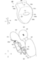
- FIG. 2 is a diagram illustrating the airbag module 105 after the operation of FIG. 1 (b) from each direction.
- FIG. 2A illustrates the airbag module 105 of FIG. 1B when viewed from slightly above the outside of the vehicle.
- a part of the panel constituting the cushion 104 is cut out to expose the inflator 112 inside.
- the cushion 104 has a shape similar to a truncated cone, with a diameter increasing from the steering 106 side (see FIG. 1A) to the occupant side (rear side of the vehicle).
- the cushion 104 is formed of a plurality of panels, and connects the front panel 120 located on the occupant side, the rear panel 122 located on the steering 106 side (see FIG. 1A), and the front panel 120 and the rear panel 122. It includes a side panel 124 that constitutes a side portion of the cushion 104.
- the side panel 124 is provided with a vent hole 126 for discharging gas.
- the inflator 112 is a device for supplying gas, and in this embodiment, a disc type (disk type) is adopted.
- the inflator 112 operates due to a shock detection signal sent from a sensor (not shown) in which a part of the gas outlet 116 formed is inserted into the cushion 104 from the rear panel 122, and gas is supplied to the cushion 104. Supply.
- the inflator 112 is provided with a plurality of stud bolts 118.
- the stud bolt 118 penetrates the rear panel 122 of the cushion 104 and is fastened to the module installation surface 109 inside the hub 108 of the steering 106 (see FIG. 4B).
- the cushion 104 is also fixed to the steering 106 by fastening the stud bolts 118 to the module installation surface 109.
- Inflators that are currently in widespread use are filled with a gas generating agent and burned to generate gas, or are filled with compressed gas and supply gas without generating heat. There is a hybrid type that uses both combustion gas and compressed gas. Any type of inflator 112 can be used.
- FIG. 2B illustrates an occupant 138 who is normally seated on the cushion 104 and the seat 102 when viewed from the left side in the vehicle width direction.
- the cushion 104 restrains the occupant 138 from the head 140 to the chest 142 and the abdomen 144 with the front panel 120 on the occupant side as the main restraining surface.
- the occupant 138 who intends to move to the front of the vehicle in an emergency comes into early contact with the upper part 104a of the cushion 104.
- the width of the upper portion 104a of the expanded and expanded cushion 104 is thicker than the width of the lower portion 104b of the cushion 104, and preferably absorbs the load from the head 140 of the occupant 138. Further, the width of the cushion 104 in the front-rear direction of the vehicle decreases toward the lower portion 104b, so that the lower portion 104b can easily enter the narrow space between the steering wheel 106 and the abdomen 144.
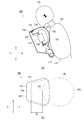
- FIG. 3 is a diagram illustrating the steering 106 of FIG. 1 (a) from each direction.
- FIG. 3A is an enlarged view of the steering wheel 106 of FIG. 1A.
- a resin cover member 110 is attached to the hub 108 at the center of the steering 106.
- the front area 150 on the occupant side of the cover member 110 is formed as a flat surface or a curved surface that widely enters the front of the view from the occupant who is normally seated on the seat 102 (see FIG. 2B) among the cover member 110. It is an area and is decorated with emblem 152 and the like.
- the vertical and horizontal directions of the cover member 110 mean the vertical and horizontal directions of the steering 106 in the neutral position.
- the vertical direction of the cover member 110 is the vertical direction when the front area 150 is viewed from the front in the steering 106 in the neutral position, and does not strictly represent the vertical direction.
- the left-right direction of the cover member 110 is the left-right direction when the front area 150 is viewed from the front in the steering 106 in the neutral position.
- the front and rear of the cover member 110 means the forward side and the reverse side of the vehicle when viewed from a certain position on the cover member 110, and does not represent the front-rear direction along a strictly horizontal straight line.
- the cover member 110 of the present embodiment is configured to open when the cushion 104 (see FIG. 1B) expands and expands, and the two cover doors 154a and 154b open to the left and right.
- the cover doors 154a and 154b are defined by a tear line 156 provided on the cover member 110.
- FIG. 3B is a sectional view taken along the line AA of the hub 108 of the steering wheel 106 of FIG. 3A.
- the airbag module 105 is housed inside the hub 108 located at the center of the rim 114 (see FIG. 3A).
- the airbag module 105 is installed on the module installation surface 109 inside the hub 108, and is covered by the cover member 110.
- the tear line 156 is provided in a groove shape on the airbag module 105 side of the cover member 110. By reducing the plate thickness of the cover member 110, the tear line 156 induces the cover member 110 to cleave when the expansion pressure is received from the cushion 104.
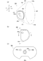
- FIG. 4 is a perspective view illustrating the cover member 110 of FIG. 3 (a) alone.
- FIG. 4A illustrates the cover member 110 before cleavage.
- the front area 150 of the cover member 110 covers the occupant side of the airbag module 105 (see FIG. 3B), and the upper surface area 158 covers the upper side of the airbag module 105.
- the tear line 156 is provided from the front area 150 to the upper surface area 158 of the cover member 110.
- FIG. 4B illustrates the cover member 110 after cleavage.
- the cover member 110 of the present embodiment is made of resin, and in a normal temperature environment (for example, about 23 ° C.), the expansion pressure of the cushion 104 causes cleavage starting from tear line 156 (see FIG. 4A). Occurs.
- the two cover doors 154a and 154b are opened to the left and right when viewed from the vicinity of the center of the front region 150.
- the cover doors 154a and 154b are formed by dividing the front area 150 and the upper surface area 158 of the cover member 110 into left and right so that the cover door 154b on the left side includes the emblem 152. Further, the cover member 110 is formed with hinges 160a and 160b connecting the main body of the cover member 110 and the cover doors 154a and 154b so that the cover doors 154a and 154b do not scatter.
- the tear line 156 continuously extends from the vicinity of the center of the front region 150 to the vicinity of the center of the upper surface region 158 while avoiding the emblem 152.
- the tear line 156 extends from the vicinity of the center toward the front end 162, branches left and right along the front end 162, and extends toward the side portions 164a and 164b of the upper surface region 158, respectively.
- the tear line 156 extends from each of the side portions 164a and 164b of the upper surface region 158 toward the front region 150.
- the tear line 156 that has reached the front area 150 extends along the side portions 168a and 168b of the front area 150, respectively.
- the tear line 156 reaches the lower end 166 of the front region 150 below the emblem 152, and is in a state of branching from the lower end 166 toward the side portions 168a and 168b of the front region 150, respectively.
- the vicinity of the center of the front area 150 is a region including the center of gravity of the area and its vicinity when the front area 150 is viewed from above in the vertical direction as a plane, or the geometry of the front area 150.
- the area including the central position and its vicinity is shown.
- the vicinity of the center of the upper surface region 158 is a region including the center of gravity of the area and its vicinity or the geometric center position of the upper surface region 158 when the upper surface region 158 is viewed from above in the vertical direction as a plane.
- a region including the vicinity thereof, or simply a region near the center line in the left-right direction of the upper surface region 158 is shown.
- the portion along the side portions 168a and 168b of the front region 150 is indestructible because a part is omitted.
- the unbreakable portion forms a pair of side hinge regions 170a and 170b that serve as hinges 160a and 160b (see FIG. 4B) of the cover door 154a.
- the pair of side hinge regions 170a and 170b are formed as regions without a tear line 156 in each of the side portions 168a and 168b of the front region 150.
- the pair of side hinge regions 170a and 170b are formed so that the axes of the hinges 160a and 160b (see FIG. 4B) are parallel to each other when viewed facing the front region 150. With this configuration, the cover doors 154a and 154b can be wide open in the direction of 180 ° to each other to form a wide opening.
- FIG. 5 is a sectional view taken along line BB of the steering wheel 106 of FIG. 3 (a).
- FIG. 5A illustrates the state of the cover member 110 before cleavage.
- the front area 150 of the cover member 110 covers the occupant side of the airbag module 105.
- the upper surface region 158 extends from the upper end of the front surface region 150 to the front of the vehicle and covers the upper surface of the airbag module 105.
- FIG. 5B illustrates the state of the cover member 110 after cleavage.
- the upper surface region 158 of the cover member 110 in consideration of safety during expansion and deployment of the cushion 104 (see FIG. 6A and the like), is widely opened. There is. More specifically, in the upper surface region 158, the inflator 112 of the airbag module 105 is installed and fixed to a position about a distance S1 away from the module installation surface 109 on the front side of the vehicle as compared with the module installation surface 109. It is configured to open across.
- the cover doors 154a and 154b are located on the front side of the upper surface area 158 from the front area 150 side to the front side of the vehicle from the module installation surface 109 (see FIG. 6B). It is formed to include a range extending to. That is, the tear line 156 extends from the vicinity of the center of the front area 150 to the front side of the vehicle with respect to the module installation surface 109 near the center of the upper surface area 158.
- FIG. 6 is a diagram illustrating the cushion 104 at the time of expansion and deployment and the occupant 138 in a non-regular seat (commonly known as out-of-position) according to FIG. 5 (b).
- FIG. 6 illustrates the cushion 104 and the occupant 138 when viewed from the left side in the vehicle width direction.
- the angle of the steering 106 can be changed as appropriate, and in a normal vehicle, the upper part of the steering 106 is tilted forward as compared with FIG. 5A.
- the cushion 104 may approach the head 140 of the occupant 138 from below, for example, when leaning out from the seat 102 (see FIG. 5).
- the cover doors 154a and 154b are opened to the left and right, so that the cover doors 154a and 154b are suppressed from being pushed upward by the cushion 104. There is. Therefore, even if the head 140 of the occupant 138 is located above the cover member 110, the push-up of the head 140 of the occupant 138 due to the cover doors 154a and 154b is prevented.
- the cover member 110 opens not only the front area 150 but also the upper surface area 158.
- the upper surface region 158 opens wider to the front of the vehicle than the module installation surface 109. Therefore, when the head 140 of the occupant 138 is located above the cover member 110, the cushion 104 can expand in front of the vehicle of the head 140 so as to avoid the head 140 of the occupant 138. At this time, since the expansion pressure toward the upper side of the cushion 104 is also dispersed in the front of the vehicle, the push-up of the head 140 of the occupant 138 by the cushion 104 is suppressed.
- FIG. 7 is a diagram illustrating an occupant 138 in a state close to the steering wheel 106 in FIG. 5 (a).
- FIG. 7A illustrates the steering 106 and the non-regular seated occupant 138 before the airbag device 100 is activated
- FIG. 7B is a view of the cover member 110 of FIG. 7A and the head 140 of the occupant 138 as viewed from above.
- the airbag device 100 as a guideline for the size of the opening of the upper surface region 158, for example, the upper surface region 158 is moved from the chin tip 141 of the occupant 138 in a state where it comes into contact with the steering 106 and has stopped moving forward to the vehicle front side. It is preferable to open over a range of 35 mm or more (S2> 35 mm).
- FMVSS208 Federal Motor Vehicle Safety Standards
- OOP non-regular seating
- restraint devices such as airbags and seat belts for occupants.
- OOP test the load received by the human dummy is measured when the human dummy is in close proximity to the airbag.
- the steering wheel 106 of the present embodiment When the steering wheel 106 of the present embodiment (see FIG. 7A) is applied to the above OOP test, the upper part of the steering wheel 106 is tilted forward at an angle of about 18 ° to 27 ° like a general steering wheel. However, there is no rim 114 on the upper side. Therefore, in the human body dummy imitating the occupant 138, the head 140 moves forward without touching the structure, and the chin tip 141 and the chest 142 are in a state of being close to the cover member 110. In a state where the forward movement of the occupant has bottomed out, as illustrated in FIG.
- the upper surface region 158 of the cover member 110 opens from the chin tip 141 of the occupant 138 to the front side of the vehicle over a range of 35 mm or more. (S2> 35 mm), as illustrated in FIG. 6, the cushion 104 can be expanded in front of the head 140, and the push-up of the head 140 by the cushion 104 can be suppressed.
- Hybrid III hybrid three
- Thor dummy Hybrid III dummies are available in multiple models that imitate people of different physiques and genders.
- the Thor dummy was developed as a successor to the Hybrid III dummy and is modeled only on men of average physique.
- the AF05 model of the Hybrid III dummy imitates a woman with a small physique.
- the seat 102 (see FIG. 1A) is often positioned in front of the adult man and the like, and the vehicle is often driven in a posture closer to the steering wheel 106. Therefore, the head of a small adult female is more likely to be located above the cover member 110 of the steering 106 than that of an adult male or the like.
- smaller adult women have lower physical tolerance and are more likely to have higher injuries than adult men.
- the upper surface region 158 of the cover member 110 is 35 mm or more from the chin tip 141 of the AF05 model to the front side of the vehicle. It may be opened over. This makes it possible to adequately ensure the safety of small adult women. Further, by applying the technical idea of the airbag device 100, even in the case of steering with different shapes and dimensions, the cover member of the steering is stopped to move forward from the occupant's jaw to the front side of the vehicle. By opening over a range of 35 mm or more, it is possible to suitably ensure the safety of the occupants.
- the cover member 110 of the present embodiment is ordered in the way of cleavage.
- a part of the tear line 156 provided in the front region 150 particularly a first thin portion 156a is provided in a range along the emblem 152.
- the second thin portion 156b is provided in the tear line 156 in a portion having a thin plate thickness next to the first thin portion 156a and in a range branched to three directions on the front end 162 side of the upper surface region 158.
- the cover member 110 is normally cleaved from the front region 150 first, starting from the first thin portion 156a.
- the cover doors 154a and 154b are opened to the left and right, and the upper surface region 158 of the cover member 110 is widely opened, so that the occupant 138 of the cushion 104 (FIG. 4A)
- the force pushing up the head 140 is reduced and dispersed to suppress the backbend of the head 140, and it is possible to improve the safety for the occupant 138 during operation.
- FIG. 8 is a diagram illustrating a first modification (cover member 200) of the cover member 110 of FIG. 4 (a).
- FIG. 8A illustrates the cover member 200 before cleavage, corresponding to FIG. 4A.
- the cover member 200 of the present embodiment is different from the cover member 110 in that the two cover doors 202a and 202b are opened vertically.
- the cover doors 202a and 202b are formed by dividing the front area 150 of the cover member 110 into upper and lower parts so that the upper cover door 202b includes the emblem 164.
- the tear line 204 crosses the front region 150 while avoiding the emblem 152, reaches the side portions 168a and 168b of the front region 150, respectively, and is in the vicinity of the side portions 164a and 164b of the upper surface region 158 along the side portions 168a and 168b. It extends to the place of. From there, the tearline 204 extends along the side portions 164a, 164b of the top surface region 158 to near the front end 162 of the top surface region 158. At this time, the tear line 204 extends along the side portions 164a and 164b of the upper surface region 158 to the front side of the vehicle from the module installation surface 109 (see FIG. 8B) of the upper surface region 158.
- the hinge of the cover door 202a is provided as a region that is the end of the tear line 204 and is indestructible due to the omission of the tear line 156 in the range on the front side of the vehicle from the module installation surface 109 of the upper surface region 158.
- the front hinge region 206 is formed.
- FIG. 8B illustrates the cover member 200 after cleavage, corresponding to FIG.
- the cover door 202a opens wider to the front side of the vehicle than the module installation surface 109, so that the cover door 202a is the occupant 138. It is possible to prevent the cushion 104 from being pushed up from below the head 140. Further, by widening the upper surface region 158 of the cover member 200, the expansion pressure of the cushion 104 can be easily dispersed to the front of the vehicle head 140 of the occupant 138. As described above, even with this configuration, it is possible to suppress the backward bending of the head 140 and enhance the safety for the occupant 138 by reducing and dispersing the force pushing up the head 140 of the occupant 138.
- FIG. 9 is a diagram illustrating a second to fourth modified example of the cover member 110 of FIG. 4 (a). Each cover member also has a different configuration from the cover member 200 of FIG. 4A in the configuration of the cover door.
- FIG. 9A illustrates the cover member 220 of the second modification.
- the tear line 224 forms a total of three cover doors, that is, the cover door 202a that opens upward and the cover doors 222a and 222b that open diagonally downward on the left and right sides, respectively.
- the cover door 202a opens wider to the front side of the vehicle than the module installation surface 109 (see FIG. 8B), so that the head of the occupant 138 via the cushion 104 is similarly opened to the cover member 200. It is possible to reduce and disperse the force pushing up the 140.
- FIG. 9B illustrates the cover member 240 of the third modification.
- the cover member 240 is composed of two cover doors 242a and 242b whose upper side opens to the left and right and a cover door 242c whose lower side opens downward by the tear line 244. Also in the cover member 240, the cover doors 242a and 242b are opened to the left and right including the vicinity of the front end 162 of the upper surface region 158, so that the head 140 of the occupant 138 of the cushion 104 can be opened in the same manner as the cover member 110 of FIG. It is possible to reduce and disperse the pushing force to suppress the backbend of the head 140 and enhance the safety for the occupant 138 during operation.
- FIG. 9C illustrates the cover member 260 of the fourth modification.
- the tear line 262 is configured so that most of the front area 150 and the upper surface area 158 are opened upward as one cover door 264.
- the cover door 264 opens wider to the front side of the vehicle than the module installation surface 109 (see FIG. 8B), so that the head of the occupant 138 via the cushion 104 is similarly opened to the cover member 200. It is possible to reduce and disperse the force pushing up the 140.
- FIG. 10 is a diagram illustrating a first modification (airbag module 300) of the airbag module 105 of FIG. 2 (a).
- FIG. 10A illustrates the internal structure of the cushion 104 through each panel of the cushion 104.
- the airbag module 300 is provided with a rectifying cloth 302 as an internal structure of the cushion 104.
- the rectifying cloth 302 is a member that guides the gas of the inflator 112 (see FIG. 2A) in a specific direction, and is contained in a bag-shaped main bag 304 that constitutes the outer surface of the cushion 104.
- the rectifying cloth 302 is connected to the rear panel 122 in a state of covering the portion including the gas outlet 116 of the inflator 112 into which the main bag 304 is inserted.
- the rectifying cloth 302 has side outlets 306a and 306b and lower outlets 306c as locations where gas is blown out from the inflator 112.
- FIG. 10B is a side view illustrating the rectifying cloth 302 of FIG. 10A.
- the rectifying cloth 302 is formed in a bag shape by sewing, and the lower edge is opened to form a lower outlet 306c.
- the lower outlet 306c is formed to have a diameter larger than that of the side outlets 306a and 306b, and the amount of gas passing through is larger than that of the side outlets 306a and 306b.
- the cushion 104 (see FIG. 10A) preferentially expands and expands from the lower part 104b side. According to this configuration, the cushion 104 allows the lower portion 104b to be inserted between the steering wheel 106 and the abdomen 142 of the occupant 138 at an early stage, and can be sandwiched between the steering wheel 106 and the abdomen 142.
- FIG. 10 (c) illustrates a state in which the rectifying cloth 302 of FIG. 10 (b) is unsewn and spread on a flat surface.
- the rectifying cloth 302 is provided with an insertion port 308 in which a part of the inflator 112 (see FIG. 2A) is inserted in the center, and is fixed to the module installation surface 109 (see FIG. 3B) together with the inflator 112. Will be done.
- FIG. 11 is a diagram illustrating the rectifying cloth 302 of FIG. 10 (b) in each direction.
- 11 (a) is a cross-sectional view taken along the line CC of the rectifying cloth 302 of FIG. 10 (b).
- 11 (a) also schematically illustrates the upper portion of the cover member 110 of FIG. 3 (a).
- the side outlets 306a and 306b are configured to emit gas diagonally upward to the left and right when viewed facing the front area 150. With this configuration, it is possible to efficiently apply gas pressure to the cover member 110 so that the cover doors 154a and 154b (see FIG. 4B) open to the left and right.
- the side outlets 306a and 306b are formed on the path connecting the inflator 112 and the tear line 156. With this configuration, the tear line 156 of the cover member 110 can be cleaved more efficiently.
- FIG. 11B illustrates a state in which the cushion 104 is expanded by using the rectifying cloth 302 of FIG. 11A. From the rectifying cloth 302 (see FIG. 11A), gas is emitted to the left and right from the side outlets 306a and 306b, but gas is not emitted directly upward. Therefore, when the head 140 of the occupant 138 (see FIG. 6) in the non-regular seating position is located above the steering 106, the cushion 104 is expanded to the left and right while suppressing the upward expansion pressure of the cushion 104. It is possible.
- FIG. 11 (c) is a DD cross-sectional view of the rectifying cloth 302 of FIG. 10 (b).
- the gas from the side outlets 306a and 306b is set to be inclined toward the front of the vehicle with respect to the vehicle width direction.
- FIG. 11 (d) illustrates the rectifying cloth 302 and the steering 106 of FIG. 10 (b) when viewed from the left side in the vehicle width direction. It is preferable that the side outlets 306a and 306b are inclined at a predetermined angle to blow out gas to the front of the vehicle, which is on the opposite side of the front region 150 (FIG. 5A), in a state where the rectifying cloth 302 is inflated. is there. Even with this configuration, as illustrated in FIG. 6, when the occupant 138 is in the non-regular seating position, the expansion pressure of the cushion 104 can be easily dispersed to the front of the vehicle.
- the cover doors 154a and 154b of the cover member 110 can be efficiently opened to the left and right. Therefore, the rectifying cloth 302 can be preferably implemented in combination with the cover member 110 (see FIG. 4A) and the cover member 240 (see FIG. 9B) having cover doors that open to the left and right. Further, by applying the technical idea of the rectifying cloth 302, the structure of the tear line and the cover door of the cover member 200 (FIG. 8), the cover member 220 (FIG. 9 (a)) and the cover member 260 (FIG. 9 (c)). It is also possible to implement a rectifying cloth with an outlet adapted to.
- FIG. 12 is a diagram illustrating a second modification (airbag module 320) of the airbag module 105 of FIG. 2 (a).
- the airbag module 320 also includes a rectifying cloth 322 as an internal structure of the cushion 104.
- the rectifying cloth 322 differs from the rectifying cloth 302 of FIG. 11 (a) in that the entire rectifying cloth 322 has a flat circular shape.
- the rectifying cloth 322 also has side outlets 306a and 306b and a lower outlet 306c, similarly to the rectifying cloth 302.
- FIG. 12B illustrates a state in which the rear panel 324 of the rectifying cloth 322 of FIG. 12A is spread out on a plane.
- the rear panel 324 is provided with an insertion port 308 in the center, and has notches along the side outlets 306a and 306b and the lower outlets 306c on the left, right, and lower edges, and a notch for making the rectifying cloth 322 round. Is formed.
- FIG. 12 (c) illustrates a state in which the front panel 326 of the rectifying cloth of FIG. 12 (a) is spread out on a plane.
- the front panel 326 has a substantially circular shape, and a rectifying cloth (see FIG. 12 (a)) can be embodied by joining the edge to the rear panel 324 (FIG. 12 (b)).
- the rectifying cloth 322 also makes it possible to efficiently open the cover doors 154a and 154b of the cover member 110 to the left and right. Therefore, the rectifying cloth 322 can be preferably implemented in combination with the cover member 110 (see FIG. 4 (a)) and the cover member 240 (FIG. 9 (b)) having cover doors that open to the left and right.
- the present invention can be used for an airbag device for a driver's seat that restrains an occupant in an emergency.
- Cover member of the first modification 202a ... Upper cover door, 202b ... Lower cover door, 204 ... tear line, 206 ... front hinge region, 220 ... cover member of the second modification, 222a ... cover door on the lower left side, 222b ... cover door on the lower right side, 240 ... cover member of the third modification, 242a ... Upper left cover door, 242b ... Upper right cover door, 242c ... Cover door, 260 ... Cover member of the fourth modification, 262 ... Tearline, 264 ... Cover door, 300 ... Airbag module of the first modification, 302 ... rectifying cloth, 304 ... main bag, 306a ... left side air outlet, 306b ... right side air outlet, 306c ... lower air outlet, 320 ... second modified air bag module, 322 ... rectifying cloth, 324 ... Rear panel of rectifying cloth 326... Front panel of rectifying cloth
Landscapes
- Engineering & Computer Science (AREA)
- Mechanical Engineering (AREA)
- Chemical & Material Sciences (AREA)
- Combustion & Propulsion (AREA)
- Transportation (AREA)
- Air Bags (AREA)
Abstract
Description
以下、上述した各構成要素の変形例について説明する。図8から図12の各図では既に説明した構成要素と同じものには同じ符号を付していて、これによって既出の構成要素については説明を省略する。また、以下の説明において、既に説明した構成要素と同じ名称のものについては、例え異なる符号を付していても、特に明記しない場合は同じ機能を有しているものとする。
図12(c)は、図12(a)の整流布のフロントパネル326を平面上に広げた状態を例示している。フロントパネル326は、ほぼ円形になっていて、縁をリアパネル324(図12(b))に接合させることで整流布(図12(a)参照)を具現化することができる。
Claims (12)
- 車両のステアリングと、インフレータおよびエアバッグクッションを含み該ステアリングに収納されるエアバッグモジュールとを備えた運転席用エアバッグ装置であって、
前記ステアリングは、
中央上部が省略された異形のリムと、
前記リムの中央に設けられ前記エアバッグモジュールが設置されるモジュール設置面と、
前記モジュール設置面に設置された前記エアバッグモジュールを覆うカバー部材と、
を含み、
前記カバー部材は、
前記エアバッグモジュールの乗員側を覆う正面領域と、
前記正面領域の上端から車両前方に延びて前記エアバッグモジュールの上側を覆う上面領域と、
前記正面領域および前記上面領域の前記エアバッグモジュール側に溝状に設けられ前記エアバッグクッションの膨張圧で開裂して該正面領域および該上面領域を1または複数のカバードアとして開かせるテアラインと、
を有し、
前記テアラインは、少なくとも前記正面領域の中央近傍から前記上面領域の中央近傍にわたって連続して延び、
前記1または複数のカバードアは、前記正面領域および前記上面領域の中央近傍から左右それぞれに開く少なくとも2つのカバードアを含むことを特徴とする運転席用エアバッグ装置。 - 前記テアラインは、前記上面領域の中央近傍から該上面領域の前端に沿って左右に分岐し該上面領域の側部に向かって延びたうえで、該上面領域の側部それぞれにおいて前記正面領域に向かって延びて該正面領域に到達しつつ該正面領域の側部それぞれに沿って延び、
前記正面領域の側部それぞれに、前記正面領域の側部に沿って延びるテアラインの一部が省略されることで破断不能になって前記2つのカバードアのヒンジとなる一対の側部ヒンジ領域が形成されていることを特徴とする請求項1に記載の運転席用エアバッグ装置 - 前記一対の側部ヒンジ領域は、前記正面領域に正対して見たとき、互いの軸が平行になるよう形成されることを特徴とする請求項2に記載の運転席用エアバッグ装置。
- 前記テアラインは、前記正面領域の中央近傍から該正面領域の下端に到達し該下端から該正面領域の側部それぞれに向かって分岐して前記一対の側部ヒンジ領域にまで延びていることを特徴とする請求項2または3に記載の運転席用エアバッグ装置。
- 車両のステアリングと、インフレータおよびエアバッグクッションを含み該ステアリングに収納されるエアバッグモジュールとを備えた運転席用エアバッグ装置であって、
前記ステアリングは、
中央上部が省略された異形のリムと、
前記リムの中央近傍に設けられ前記エアバッグモジュールが設置されるモジュール設置面と、
前記モジュール設置面に設置された前記エアバッグモジュールを覆うカバー部材と、
を含み、
前記カバー部材は、
前記エアバッグモジュールの乗員側を覆う正面領域と、
前記正面領域の上端から車両前方に延びて前記エアバッグモジュールの上側を覆う上面領域と、
前記正面領域および前記上面領域の前記エアバッグモジュール側に溝状に設けられ前記エアバッグクッションの膨張圧で開裂して該正面領域および該上面領域を1または複数のカバードアとして開かせるテアラインと、
を有し、
前記テアラインは、少なくとも前記正面領域を横断して該正面領域の側部それぞれに到達して該側部に沿って前記上面領域の側部近傍の箇所にまで延び、該上面領域の側部近傍の箇所それぞれから該上面領域の側部に沿って該上面領域の前記モジュール設置面よりも車両前側にまで延びていて、
前記1または複数のカバードアは、上方に開く少なくとも1つのカバードアを含むことを特徴とする運転席用エアバッグ装置。 - 前記上面領域のうち前記モジュール設置面よりも車両前側の所定範囲に、前記テアラインが省略されることで破断不能になって前記1つのカバードアのヒンジとなる前部ヒンジ領域が形成されていることを特徴とする請求項5に記載の運転席用エアバッグ装置。
- 前記1または複数のカバードアは、前記上面領域のうち、前記ステアリングに接触して車両前方への移動が停止した状態の乗員の顎先から車両前側に35mm以上にわたって形成されることを特徴とする請求項1から6のいずれか1項に記載の運転席用エアバッグ装置
- 前記1または複数のカバードアは、前記上面領域のうち前記正面領域側から前記モジュール設置面よりも車両前側にまでわたる範囲を含んで形成されることを特徴とする請求項1から7のいずれか1項に記載の運転席用エアバッグ装置。
- 前記正面領域に設けられたテアラインの一部は、前記上面領域に設けられたテアラインよりも薄肉であることを特徴とする請求項1から8のいずれか1項に記載の運転席用エアバッグ装置。
- 前記エアバッグクッションは、袋状のメインバッグと、該メインバッグに内包されていて前記インフレータのガス噴出口を含む部分が覆われる整流布とを有し、
前記整流布は、前記インフレータから供給されたガスが吹き出る1または複数の吹出口を有し、
前記1または複数の吹出口は、前記正面領域に正対して見たとき、左右の斜め上方にガスが出ることを特徴とする請求項1から9のいずれか1項に記載の運転席用エアバッグ装置。 - 前記1または複数の吹出口は、前記インフレータと前記テアラインとを結ぶ経路上に形成されていることを特徴とする請求項10に記載の運転席用エアバッグ装置。
- 前記1または複数の吹出口は、車幅方向から見たとき、前記正面領域とは反対側に傾斜してガスが出ることを特徴とする請求項10または11に記載の運転席用エアバッグ装置。
Priority Applications (6)
| Application Number | Priority Date | Filing Date | Title |
|---|---|---|---|
| CN202080057949.9A CN114222685B (zh) | 2019-09-17 | 2020-08-03 | 驾驶座用安全气囊装置 |
| JP2021546539A JP7316364B2 (ja) | 2019-09-17 | 2020-08-03 | 運転席用エアバッグ装置 |
| CN202311325617.6A CN117261810A (zh) | 2019-09-17 | 2020-08-03 | 驾驶座用安全气囊装置 |
| US17/753,763 US11794681B2 (en) | 2019-09-17 | 2020-08-03 | Driver seat airbag device |
| KR1020227012102A KR102678248B1 (ko) | 2019-09-17 | 2020-08-03 | 운전석용 에어백 장치 |
| EP20865330.3A EP4032756B1 (en) | 2019-09-17 | 2020-08-03 | Driver seat airbag device |
Applications Claiming Priority (2)
| Application Number | Priority Date | Filing Date | Title |
|---|---|---|---|
| JP2019168778 | 2019-09-17 | ||
| JP2019-168778 | 2019-09-17 |
Publications (1)
| Publication Number | Publication Date |
|---|---|
| WO2021053982A1 true WO2021053982A1 (ja) | 2021-03-25 |
Family
ID=74883006
Family Applications (1)
| Application Number | Title | Priority Date | Filing Date |
|---|---|---|---|
| PCT/JP2020/029689 WO2021053982A1 (ja) | 2019-09-17 | 2020-08-03 | 運転席用エアバッグ装置 |
Country Status (6)
| Country | Link |
|---|---|
| US (1) | US11794681B2 (ja) |
| EP (1) | EP4032756B1 (ja) |
| JP (1) | JP7316364B2 (ja) |
| KR (1) | KR102678248B1 (ja) |
| CN (2) | CN117261810A (ja) |
| WO (1) | WO2021053982A1 (ja) |
Cited By (2)
| Publication number | Priority date | Publication date | Assignee | Title |
|---|---|---|---|---|
| US11993220B2 (en) * | 2020-09-01 | 2024-05-28 | Autoliv Development Ab | Driverseat airbag device |
| JP7544002B2 (ja) | 2021-08-25 | 2024-09-03 | 豊田合成株式会社 | ハンドル用エアバッグ装置 |
Families Citing this family (6)
| Publication number | Priority date | Publication date | Assignee | Title |
|---|---|---|---|---|
| WO2020217824A1 (ja) * | 2019-04-25 | 2020-10-29 | オートリブ ディベロップメント エービー | ドライバエアバッグ装置 |
| CN113853324B (zh) * | 2019-06-18 | 2023-11-03 | 奥托立夫开发公司 | 驾驶座用安全气囊装置 |
| US12060023B2 (en) * | 2019-12-05 | 2024-08-13 | Autoliv Development Ab | Driver airbag device |
| KR102702636B1 (ko) * | 2019-12-19 | 2024-09-06 | 아우토리브 디벨롭먼트 아베 | 스티어링 휠 |
| JP7514951B2 (ja) * | 2020-12-03 | 2024-07-11 | オートリブ ディベロップメント エービー | エアバッグ装置 |
| US20240149823A1 (en) * | 2022-11-03 | 2024-05-09 | Divergent Technologies, Inc | Driver airbag cover |
Citations (12)
| Publication number | Priority date | Publication date | Assignee | Title |
|---|---|---|---|---|
| JPH09202243A (ja) * | 1995-12-22 | 1997-08-05 | Mando Mach Corp | 車輛用ハンドル |
| JPH11342819A (ja) * | 1998-06-02 | 1999-12-14 | Honda Motor Co Ltd | エアバッグ装置 |
| US20050121889A1 (en) * | 2003-12-08 | 2005-06-09 | Enders Mark L. | Non-circular steering wheel assembly and airbag module |
| JP2007062469A (ja) * | 2005-08-30 | 2007-03-15 | Toyoda Gosei Co Ltd | エアバッグ装置 |
| JP2008030718A (ja) | 2006-07-31 | 2008-02-14 | Nippon Plast Co Ltd | エアバッグ装置のカバー体、エアバッグ装置、及びステアリングホイール |
| JP2008049858A (ja) * | 2006-08-25 | 2008-03-06 | Toyota Motor Corp | 運転席用エアバッグ装置 |
| JP2008094341A (ja) * | 2006-10-16 | 2008-04-24 | Toyota Motor Corp | 車両用ステアリング装置 |
| JP2008173994A (ja) * | 2007-01-16 | 2008-07-31 | Toyota Motor Corp | 車両のエアバック装置 |
| JP2008201251A (ja) * | 2007-02-20 | 2008-09-04 | Toyota Motor Corp | 車両用ステアリング装置 |
| JP2008273480A (ja) * | 2007-05-07 | 2008-11-13 | Toyota Motor Corp | 車両用ステアリング装置 |
| JP2008296760A (ja) * | 2007-05-31 | 2008-12-11 | Toyota Motor Corp | 車両用ステアリング装置 |
| JP2018122798A (ja) * | 2017-02-02 | 2018-08-09 | 豊田合成株式会社 | エアバッグ |
Family Cites Families (28)
| Publication number | Priority date | Publication date | Assignee | Title |
|---|---|---|---|---|
| US5730460A (en) * | 1996-11-22 | 1998-03-24 | General Motors Corporation | Air bag cover |
| US6168189B1 (en) * | 1998-09-14 | 2001-01-02 | Breed Automotive Technology, Inc. | Airbag cover |
| DE10011066A1 (de) * | 2000-03-07 | 2001-09-13 | Delphi Tech Inc | Luftsackmodul |
| US7004497B2 (en) * | 2003-01-07 | 2006-02-28 | General Motors Corporation | Styling flexible driver air bag module and method of making same |
| DE20304056U1 (de) * | 2003-03-05 | 2003-06-12 | TAKATA-PETRI AG, 63743 Aschaffenburg | Zierelement für Abdeckkappen von Airbagmodulen |
| JP2006001326A (ja) * | 2004-06-15 | 2006-01-05 | Takata Corp | エアバッグカバー、エアバッグ装置 |
| KR20060024971A (ko) * | 2004-09-15 | 2006-03-20 | 현대모비스 주식회사 | 에어백장치 |
| US7390013B2 (en) * | 2005-03-10 | 2008-06-24 | Tk Holdings Inc. | Airbag module |
| JP4848141B2 (ja) * | 2005-06-08 | 2011-12-28 | マツダ株式会社 | エアバッグ装置 |
| EP1790538A3 (en) * | 2005-11-28 | 2008-09-03 | Toyoda Gosei Co., Ltd. | Airbag apparatus |
| EP1980453B1 (en) * | 2006-02-03 | 2011-08-31 | Takata Corporation | Air bag and air bag system |
| KR20080030718A (ko) | 2006-10-02 | 2008-04-07 | 이일우 | 알로에와 통밀이 첨가된 찹쌀 바게트의 제조방법 |
| JP4950814B2 (ja) * | 2007-08-31 | 2012-06-13 | 日本プラスト株式会社 | エアバッグ装置付きステアリングホイール |
| JP5322275B2 (ja) * | 2009-02-06 | 2013-10-23 | タカタ株式会社 | エアバッグ装置 |
| KR101063390B1 (ko) * | 2009-02-09 | 2011-09-07 | 현대자동차주식회사 | 운전석 에어백 커버 |
| JP5950444B2 (ja) * | 2012-04-27 | 2016-07-13 | 日本プラスト株式会社 | エアバッグ装置のカバー体 |
| KR102095565B1 (ko) * | 2013-11-01 | 2020-03-31 | 현대모비스 주식회사 | 운전석 에어백 |
| US9283921B2 (en) * | 2013-11-21 | 2016-03-15 | Ford Global Technologies, Llc | Driver airbag module having multiple deployment paths |
| US9333937B1 (en) * | 2014-12-10 | 2016-05-10 | Autoliv Asp, Inc. | Airbag cover with stress relief features |
| US9694780B1 (en) * | 2016-03-17 | 2017-07-04 | Autoliv Asp, Inc. | Airbag cover with breakaway-resistant features |
| JP6628408B2 (ja) * | 2016-03-29 | 2020-01-08 | 日本プラスト株式会社 | エアバッグ装置のカバー体 |
| US10427638B2 (en) * | 2016-06-08 | 2019-10-01 | Autoliv Asp, Inc. | Frontal airbag assemblies for reducing rotational velocity of a head of an occupant |
| US20170355341A1 (en) * | 2016-06-09 | 2017-12-14 | Autoliv Asp, Inc. | Airbag cushions for eccentric steering wheels and related systems and methods |
| JP6876817B2 (ja) * | 2017-10-05 | 2021-05-26 | オートリブ ディベロップメント エービー | エアバッグ装置 |
| KR20210123368A (ko) * | 2019-02-07 | 2021-10-13 | 아우토리브 디벨롭먼트 아베 | 운전석 에어백 |
| US11254275B2 (en) * | 2019-03-27 | 2022-02-22 | Toyoda Gosei Co., Ltd. | Airbag device for a driver's seat |
| KR102659563B1 (ko) * | 2019-05-22 | 2024-04-22 | 현대모비스 주식회사 | 에어백 커버장치 |
| JP7192712B2 (ja) * | 2019-08-21 | 2022-12-20 | トヨタ自動車株式会社 | エアバッグ装置 |
-
2020
- 2020-08-03 CN CN202311325617.6A patent/CN117261810A/zh active Pending
- 2020-08-03 CN CN202080057949.9A patent/CN114222685B/zh active Active
- 2020-08-03 US US17/753,763 patent/US11794681B2/en active Active
- 2020-08-03 KR KR1020227012102A patent/KR102678248B1/ko active IP Right Grant
- 2020-08-03 EP EP20865330.3A patent/EP4032756B1/en active Active
- 2020-08-03 JP JP2021546539A patent/JP7316364B2/ja active Active
- 2020-08-03 WO PCT/JP2020/029689 patent/WO2021053982A1/ja unknown
Patent Citations (12)
| Publication number | Priority date | Publication date | Assignee | Title |
|---|---|---|---|---|
| JPH09202243A (ja) * | 1995-12-22 | 1997-08-05 | Mando Mach Corp | 車輛用ハンドル |
| JPH11342819A (ja) * | 1998-06-02 | 1999-12-14 | Honda Motor Co Ltd | エアバッグ装置 |
| US20050121889A1 (en) * | 2003-12-08 | 2005-06-09 | Enders Mark L. | Non-circular steering wheel assembly and airbag module |
| JP2007062469A (ja) * | 2005-08-30 | 2007-03-15 | Toyoda Gosei Co Ltd | エアバッグ装置 |
| JP2008030718A (ja) | 2006-07-31 | 2008-02-14 | Nippon Plast Co Ltd | エアバッグ装置のカバー体、エアバッグ装置、及びステアリングホイール |
| JP2008049858A (ja) * | 2006-08-25 | 2008-03-06 | Toyota Motor Corp | 運転席用エアバッグ装置 |
| JP2008094341A (ja) * | 2006-10-16 | 2008-04-24 | Toyota Motor Corp | 車両用ステアリング装置 |
| JP2008173994A (ja) * | 2007-01-16 | 2008-07-31 | Toyota Motor Corp | 車両のエアバック装置 |
| JP2008201251A (ja) * | 2007-02-20 | 2008-09-04 | Toyota Motor Corp | 車両用ステアリング装置 |
| JP2008273480A (ja) * | 2007-05-07 | 2008-11-13 | Toyota Motor Corp | 車両用ステアリング装置 |
| JP2008296760A (ja) * | 2007-05-31 | 2008-12-11 | Toyota Motor Corp | 車両用ステアリング装置 |
| JP2018122798A (ja) * | 2017-02-02 | 2018-08-09 | 豊田合成株式会社 | エアバッグ |
Non-Patent Citations (1)
| Title |
|---|
| See also references of EP4032756A4 |
Cited By (2)
| Publication number | Priority date | Publication date | Assignee | Title |
|---|---|---|---|---|
| US11993220B2 (en) * | 2020-09-01 | 2024-05-28 | Autoliv Development Ab | Driverseat airbag device |
| JP7544002B2 (ja) | 2021-08-25 | 2024-09-03 | 豊田合成株式会社 | ハンドル用エアバッグ装置 |
Also Published As
| Publication number | Publication date |
|---|---|
| CN117261810A (zh) | 2023-12-22 |
| EP4032756B1 (en) | 2024-10-09 |
| JP7316364B2 (ja) | 2023-07-27 |
| EP4032756A4 (en) | 2023-10-11 |
| US11794681B2 (en) | 2023-10-24 |
| JPWO2021053982A1 (ja) | 2021-03-25 |
| KR20220061216A (ko) | 2022-05-12 |
| KR102678248B1 (ko) | 2024-06-26 |
| CN114222685A (zh) | 2022-03-22 |
| CN114222685B (zh) | 2023-11-07 |
| EP4032756A1 (en) | 2022-07-27 |
| US20220379832A1 (en) | 2022-12-01 |
Similar Documents
| Publication | Publication Date | Title |
|---|---|---|
| WO2021053982A1 (ja) | 運転席用エアバッグ装置 | |
| US7407185B2 (en) | Passenger airbag with a diffuser | |
| JP3906741B2 (ja) | 乗員保護装置 | |
| US7390013B2 (en) | Airbag module | |
| CN109895726A (zh) | 车辆用安全气囊 | |
| WO2020170864A1 (ja) | 運転席用エアバッグ装置 | |
| JP6365589B2 (ja) | 車両用乗員保護装置 | |
| US11267433B2 (en) | Side airbag device and vehicle seat provided with same | |
| US11912228B2 (en) | Occupant crash protection for vehicle | |
| JP2019043482A (ja) | 車両用オットマン装置 | |
| KR20210009121A (ko) | 루프 에어백 장치 | |
| KR980008857A (ko) | 차량의 사이드 에어백 장치 | |
| KR20220019050A (ko) | 운전석용 에어백 장치 | |
| JP7381772B2 (ja) | シート内蔵エアバッグ装置 | |
| JP2006117235A (ja) | エアバッグ装置 | |
| JPH11123995A (ja) | 自動車のエアバッグ装置 | |
| JP2004188176A (ja) | 自動車シート | |
| JPH0624282A (ja) | 自動車のエアバッグ装置 | |
| JP2018100000A (ja) | 車両用乗員拘束装置 | |
| JPH0672275A (ja) | 自動車のエアバッグ配設構造 | |
| JPH10329636A (ja) | ヘッドレストのエアバッグ装置 | |
| KR102638130B1 (ko) | 자동차의 조수석 에어백 장치 | |
| JPH0672274A (ja) | 自動車のエアバッグ配設構造 | |
| WO2021002076A1 (ja) | エアバッグ、エアバッグ装置、車両用シート及びエアバッグシステム | |
| JPH1053091A (ja) | 車両用シートのエアバッグ装置 |
Legal Events
| Date | Code | Title | Description |
|---|---|---|---|
| 121 | Ep: the epo has been informed by wipo that ep was designated in this application |
Ref document number: 20865330 Country of ref document: EP Kind code of ref document: A1 |
|
| ENP | Entry into the national phase |
Ref document number: 2021546539 Country of ref document: JP Kind code of ref document: A |
|
| NENP | Non-entry into the national phase |
Ref country code: DE |
|
| ENP | Entry into the national phase |
Ref document number: 20227012102 Country of ref document: KR Kind code of ref document: A |
|
| ENP | Entry into the national phase |
Ref document number: 2020865330 Country of ref document: EP Effective date: 20220419 |