WO2021038841A1 - ドリル - Google Patents
ドリル Download PDFInfo
- Publication number
- WO2021038841A1 WO2021038841A1 PCT/JP2019/034179 JP2019034179W WO2021038841A1 WO 2021038841 A1 WO2021038841 A1 WO 2021038841A1 JP 2019034179 W JP2019034179 W JP 2019034179W WO 2021038841 A1 WO2021038841 A1 WO 2021038841A1
- Authority
- WO
- WIPO (PCT)
- Prior art keywords
- drill
- flute
- ridge line
- radial
- gash
- Prior art date
Links
Images


Classifications
-
- B—PERFORMING OPERATIONS; TRANSPORTING
- B23—MACHINE TOOLS; METAL-WORKING NOT OTHERWISE PROVIDED FOR
- B23B—TURNING; BORING
- B23B51/00—Tools for drilling machines
- B23B51/02—Twist drills
-
- B—PERFORMING OPERATIONS; TRANSPORTING
- B23—MACHINE TOOLS; METAL-WORKING NOT OTHERWISE PROVIDED FOR
- B23B—TURNING; BORING
- B23B2251/00—Details of tools for drilling machines
- B23B2251/04—Angles, e.g. cutting angles
-
- B—PERFORMING OPERATIONS; TRANSPORTING
- B23—MACHINE TOOLS; METAL-WORKING NOT OTHERWISE PROVIDED FOR
- B23B—TURNING; BORING
- B23B2251/00—Details of tools for drilling machines
- B23B2251/08—Side or plan views of cutting edges
-
- B—PERFORMING OPERATIONS; TRANSPORTING
- B23—MACHINE TOOLS; METAL-WORKING NOT OTHERWISE PROVIDED FOR
- B23B—TURNING; BORING
- B23B2251/00—Details of tools for drilling machines
- B23B2251/08—Side or plan views of cutting edges
- B23B2251/082—Curved cutting edges
-
- B—PERFORMING OPERATIONS; TRANSPORTING
- B23—MACHINE TOOLS; METAL-WORKING NOT OTHERWISE PROVIDED FOR
- B23B—TURNING; BORING
- B23B2251/00—Details of tools for drilling machines
- B23B2251/14—Configuration of the cutting part, i.e. the main cutting edges
-
- B—PERFORMING OPERATIONS; TRANSPORTING
- B23—MACHINE TOOLS; METAL-WORKING NOT OTHERWISE PROVIDED FOR
- B23B—TURNING; BORING
- B23B2251/00—Details of tools for drilling machines
- B23B2251/18—Configuration of the drill point
-
- B—PERFORMING OPERATIONS; TRANSPORTING
- B23—MACHINE TOOLS; METAL-WORKING NOT OTHERWISE PROVIDED FOR
- B23B—TURNING; BORING
- B23B2251/00—Details of tools for drilling machines
- B23B2251/18—Configuration of the drill point
- B23B2251/182—Web thinning
-
- B—PERFORMING OPERATIONS; TRANSPORTING
- B23—MACHINE TOOLS; METAL-WORKING NOT OTHERWISE PROVIDED FOR
- B23B—TURNING; BORING
- B23B2251/00—Details of tools for drilling machines
- B23B2251/20—Number of cutting edges
- B23B2251/202—Three cutting edges
Definitions
- the present invention relates to a drill.
- a thinning blade and an R gash are provided at the tip of the body.
- the thinning blade is formed from the inner end of the cutting edge toward the chisel by performing a thinning process for reducing the remaining width of the chisel at the center of the drill.
- the R gash is formed so as to extend in an arc shape from the inner end side of the thinning blade toward the outer peripheral surface of the body.
- the body is provided with a discharge groove for discharging chips from the work during processing.
- the radial outer end of the R gash is connected to the discharge groove on the radial inner side of the outer peripheral surface of the body so that chips of the work do not flow to the outer peripheral side of the body during machining.
- An object of the present invention is to provide a drill capable of improving chip evacuation during machining and stabilizing cutting resistance at a low level.
- the drill according to one aspect of the present invention includes a body extending about an axial center, a plurality of discharge grooves spirally provided on the outer peripheral surface of the body from the tip end portion to the base end portion of the body, and the same.
- a cutting edge provided at a ridge between an inner surface of the discharge groove facing the rotation direction side of the body and a flank surface of the body at the tip portion, and a diameter from the radial inner end of the body of the cutting edge.
- An R portion in which the first ridge line between the thinning blade extending inward in the direction and the flank surface is curved in the rotational direction from the radial inner end of the thinning blade toward the radial outer side.
- the second ridge line with the flank extends linearly from the radial outer end of the first ridge line toward the radial outer side, and the discharge groove is radially inside the outer peripheral surface of the body. It is characterized by having a gash portion having a straight portion connected to the.
- the curl of chips becomes stronger depending on the R portion of the gash portion.
- the chips are finely divided and the chip shape is stabilized.
- the straight portion is connected to the discharge groove radially inside the outer peripheral surface of the body, the straight portion allows the chips to be smoothly discharged not in the direction toward the outer peripheral surface of the body but in the direction toward the discharge groove. Therefore, the drill can improve the chip evacuation property during machining and can stabilize the cutting resistance at a low level.
- the distance from the axis to the position where the second ridge line connects to the discharge groove may be 30% or more and 45% or less of the outer diameter of the body.
- the generated chips have a stable curl shape due to the R portion, so that the shape of the chips is stable. Therefore, the drill can stabilize the chip evacuation of the work during machining.
- the angle between the tangent line at the radial outer end of the first ridge line and the second ridge line when viewed from the direction in which the axis extends is 20 ° or less. There may be.
- the curled chips are stably discharged into the discharge groove by the straight portion. Therefore, the drill can stabilize the chip evacuation of the work during machining.
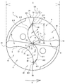
- the three-flute drill 1 is substantially cylindrical and includes a shank 2 and a body 3.
- the shank 2 is held by a spindle of a machine tool (not shown).
- the body 3 extends from the shank 2 about the axis AX.
- the end of the body 3 on the shank 2 side (right side in FIG. 1) is referred to as the "base end of the body 3", and the end of the body 3 on the side opposite to the shank 2 (left side in FIG. 1). Is called “the tip of the body 3".
- the radial direction of the body 3 is simply referred to as "diameter direction”.
- the axis AX is orthogonal to the radial direction.
- the three-flute drill 1 cuts a workpiece by rotating around the axis AX to form a machined hole.
- the rotation direction R of the three-flute drill 1 during machining is a counterclockwise direction when viewed from the tip end side of the body 3 (hereinafter, referred to as “front view”).
- Three discharge grooves 4 are provided on the outer peripheral surface 31 of the body 3. Each of the three discharge grooves 4 opens at the tip of the body 3.
- the three discharge grooves 4 are formed spirally in the clockwise direction in the front view from the tip end portion of the body 3 to the base end portion of the body 3, respectively.
- the discharge groove 4 discharges chips from the machined hole during machining.
- the discharge groove 4 is composed of an inner surface 41 facing the rotation direction R side and an inner surface 42 facing the side opposite to the rotation direction R.
- the ridgeline portion where the inner surface 41 and the outer peripheral surface 31 intersect is the leading edge 33.
- the ridgeline portion where the inner surface 42 and the outer peripheral surface 31 intersect is the heel 34.
- a flank 6 is formed at the tip of the body 3.
- the flank 6 extends from the end of each inner surface 41 on the tip end side of the body 3 in a direction opposite to the rotation direction R and inclined toward the base end portion side of the body 3.
- a cutting edge 5 is provided at a ridgeline portion where the inner surface 41 and the flank 6 intersect.
- the cutting edge 5 has a substantially S-shaped front view and cuts a workpiece.
- the inner surface 41 near the cutting edge 5 is a so-called rake surface that scoops chips cut by the cutting edge 5.
- a chisel 9 is formed at the center of the tip of the body 3.
- a thinning blade 7 is formed in the vicinity of the chisel 9.
- the thinning blade 7 extends radially inward from the radial inner end 51 of the cutting edge 5 (that is, toward the chisel 9) in an arc shape curved in the front view rotation direction R.
- the thinning blade 7 is provided on the ridge line portion between the thinning surface 71 and the flank surface 6.
- the thinning surface 71 extends from the thinning blade 7 toward the base end portion side of the body 3 and faces the rotation direction R side.
- the thinning surface 71 is a so-called rake surface.
- a gash portion 8 is formed at the tip of the body 3.
- the gash portion 8 is provided on the tip end side of the body 3 of the inner surface 42, and is formed in a surface shape facing the side opposite to the rotation direction R.
- the gash portion 8 curls the chips scooped by the rake face during processing and discharges them into the discharge groove 4.
- the gash portion 8 has an R portion 81 and a straight portion 82.
- the ridgeline between the R portion 81 and the flank 6 is referred to as “first ridgeline 811”, and the ridgeline between the straight portion 82 and the flank 6 is referred to as “second ridgeline 821”.
- the first ridge line 811 curves and extends in the front view rotation direction R from the radial inner end 72 of the thinning blade 7 toward the radial outer side.
- FIG. 3 shows a portion of the first ridge line 811 extending radially outward from the radial outer end 812 (the same applies to FIGS. 5 and 6).
- the R portion 81 extends from the first ridge line 811 toward the base end portion side of the body 3, and is formed in a curved surface shape curved in the front view rotation direction R side. The curl of the chips cut by the thinning blade 7 is strengthened by the R portion 81.
- the second ridge line 821 extends linearly from the radial outer end 812 of the first ridge line 811 toward the radial outer side.
- the radial outer end 822 of the second ridge line 821 is connected to the discharge groove 4 on the radial inner side of the outer peripheral surface 31.
- the portion extending radially outward from the radial outer end 812 of the first ridge 811 is radially inside the position where it is connected to the discharge groove 4, and the second ridge 821 is connected to the discharge groove 4.
- the straight portion 82 extends from the second ridge line 821 toward the base end portion side of the body 3 so as to be away from the axial center AX, and is formed along the inner surface 42.
- the boundary line between the R portion 81 and the straight portion 82 is shown by a solid straight line for convenience in FIG. 3 (the same applies to FIGS. 5 and 6), the discharge is actually twisted spirally with the straight portion 82. Since the boundary line is formed by the interference of the groove 4, the boundary line does not become a straight line when viewed from the front. That is, the boundary line is formed so as to curve along the discharge groove 4.
- the chips curled by the R portion 81 are guided by the straight portion 82 so as to flow through the discharge groove 4 toward the base end portion side of the body 3.
- An arc groove 10 is formed at the connecting portion between the radial inner end of the R portion 81 and the radial inner end of the thinning surface 71.
- the arc groove 10 extends from the chisel 9 toward the discharge groove 4 and is formed in an arc shape curved inward in the front radial direction.
- the arc groove 10 smoothly flows the chips scooped up by the thinning surface 71 to the gash portion 8.
- Chips are pushed out to the base end side of the body 3 through the discharge groove 4.
- the straight portion 82 is provided as a wall on the heel 34 side of the R portion 81, the chips are restrained by the wall of the gash portion 8.
- the curl of the chips becomes stronger, and the chips are finely sheared.
- the R portion 81 of the gash portion 8 increases the curl of chips.
- the chips are finely divided and the chip shape is stabilized.
- the sheared chips flow through the discharge groove 4 toward the base end portion side of the body 3 and are discharged to the outside from the machined hole.
- the three-flute drill 1 can improve the chip evacuation property during machining and stabilize the cutting resistance at a low level.
- the two-flute drill 101 according to the second embodiment of the present invention will be described with reference to FIGS. 4 and 5.
- the basic configuration of the two-flute drill 101 and the movement of chips generated during machining by the two-flute drill 101 are substantially the same as those of the three-flute drill 1.
- the two-flute drill 101 has a different number of blades from the three-flute drill 1.
- the configuration having the same function as that of the first embodiment is designated by the same reference numerals as those of the first embodiment, and the two-flute drill 101 will be briefly described.
- two discharge grooves 4 are provided on the outer peripheral surface 31 of the body 3.
- a flank 6 is formed at the tip of the body 3.
- a cutting edge 5 is provided at a ridgeline portion where the inner surface 41 and the flank 6 intersect.
- the gash portion 8 has an R portion 81 and a straight portion 82 as in the first embodiment.
- the first ridge line 811 curves and extends in the front view rotation direction R from the radial inner end 72 of the thinning blade 7 toward the radial outer side.
- the R portion 81 extends from the first ridge line 811 toward the base end portion side of the body 3, and is formed in a curved surface shape curved in the front view rotation direction R side.
- the second ridge line 821 extends linearly from the radial outer end 812 of the first ridge line 811 toward the radial outer side.
- the radial outer end 822 of the second ridge line 821 is connected to the discharge groove 4 on the radial inner side of the outer peripheral surface 31.
- the straight portion 82 extends from the second ridge line 821 toward the base end portion side of the body 3 so as to be away from the axial center AX, and is formed along the inner surface 42.
- the present invention is not limited to each of the above embodiments, and various modifications can be made.
- the rotation direction R may be a front view clockwise direction.
- the arc groove 10 may not be provided. That is, the connecting portion between the thinning blade 7 and the R portion 81 may be angular.
- the number of blades is not limited to the above embodiment.
- the above embodiment may be a so-called double-margin drill in which a back punch is provided in an intermediate portion between the leading edge 33 and the heel 34, or a so-called single-margin drill in which the back punch reaches the heel 34. , You don't have to pull out the back.
- the second ridge line 821 may be connected to the discharge groove 4 at the same position as the position where the portion extending the first ridge line 811 radially outward from the radial outer end 812 is connected to the discharge groove 4 or the radial outer side. ..
- the second ridge line 821 extends linearly from the radial outer end 812 of the first ridge line 811 toward the radial outer side.
- the second ridge line 821 is in the front view rotation direction from the radial outer end 812 of the first ridge line 811 toward the radial outer side. It curves and extends toward R.
- the radius of curvature of the second ridge line 821 may be larger than the radius of curvature of the first ridge line 811.
- the portion extending radially outward from the end 812 of the first ridge line 811 is radially inside the position where it is connected to the discharge groove 4, and the second ridge line 821 is connected to the discharge groove 4.
- the two-flute drill 102 can improve the chip evacuation property during machining and stabilize the cutting resistance at a low level.
- the three-flute drill 1 can also be deformed in the same manner.
- the outer diameter of the body 3 is defined as “outer diameter D”.
- the angle between the tangent line T and the second ridge line 821 at the radial outer end 812 of the first ridge line 811 in the front view is defined as the “tangent angle ⁇ ”.
- the distance from the axial center AX to the radial outer end 822 of the second ridge line 821 (that is, the position where the second ridge line 821 connects to the discharge groove 4) in the front view is defined as "distance L”.
- the drill life due to the difference in the tangential angle ⁇ and the distance L, the conventional three-flute drill, and the conventional two-flute A first test was conducted to confirm the difference in drill life from the drill.
- the tangent angle ⁇ was changed from 4 ° to 24 ° in 4 ° increments.
- the distance L was changed from 0.27D to 0.48D in steps of 0.03D (that is, 3% of the outer diameter D, the same applies hereinafter) (see FIGS. 7 and 8). Since the conventional drill does not have the straight portion 82, the concept of the tangential angle ⁇ does not exist.
- the distance L in the conventional drill corresponds to the distance from the axial center AX to the radial outer end 812 of the first ridge line 811.
- the criteria for determining the results of the first test are as follows. ⁇ : When the total cutting length is 50 m, the drill is not broken or chipped, and the wear width of the flank 6 is 0.2 mm or less. ⁇ : When the drill is broken or broken before the total cutting length reaches 50 m, or when the wear width of the flank 6 exceeds 0.2 mm when the total cutting length reaches 50 m. X: When the drill is broken or broken at the initial point (until the number of drilled holes reaches 10 holes).
- the judgment result was generally " ⁇ " when the tangential angle ⁇ was 20 ° or less.
- the judgment result was generally “ ⁇ ”.
- the judgment result was generally “ ⁇ ”.
- the tangent angle ⁇ was 20 ° or less and the distance L was 0.30D or more and 0.45D or less, all the judgment results were “ ⁇ ”.
- the three-flute drill 1 and the two-flute drill 101 can obtain a long and stable drill life when the tangential angle ⁇ is 20 ° or less.
- the generated chips become a stable curl shape by the R portion 81, so that the chip shape becomes stable. Therefore, the three-flute drill 1 and the two-flute drill 101 can further stabilize the chip evacuation property of the work during machining.
- the distance L is 0.30D or more and 0.45D or less.
- the curled chips are stably discharged to the discharge groove 4 by the straight portion 82. Therefore, the three-flute drill 1 and the two-flute drill 101 can stabilize the chip evacuation of the work during machining.
- the tangential angle ⁇ is preferably 20 ° or less, and the distance L is preferably 0.30D or more and 0.45D or less.
- the tangential angle ⁇ may be larger than 20 °.
- the distance L may be smaller than 0.30D or larger than 0.45D.
- the determination result is “ ⁇ ” (see FIG. 7).
- the determination result is “ ⁇ ” (see FIG. 8).
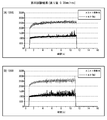
- the horizontal axis corresponds to the number of durable holes
- the vertical axis corresponds to each of the three-flute drills 1A (N1 to N3), 1B (N1 to N3), and 1C (N1 to N3).
- the number of durable holes of the three-flute drills 1A (N1 to N3) was 1200 holes (upper limit of the second test). That is, it was confirmed that the number of durable holes of the three-flute drill 1A is 1200 holes or more.
- the conventional three-flute drill 1B (N1) has 1200 holes (upper limit of the second test), the conventional three-flute drill 1B (N2) has 960 holes, and the conventional three-flute drill 1B.
- the number of durable holes in (N3) was 1060. Specifically, the conventional three-flute drill 1B (N2) was defective at 960 holes, and the conventional three-flute drill 1B (N3) was defective at 1060 holes.
- the number of durable holes of the conventional three-flute drill 1C (N1) is 800
- the number of durable holes of the conventional three-flute drill 1C (N2) is 102
- the number of durable holes of the conventional three-flute drill 1C (N3) has 48 holes.
- the conventional three-flute drill 1C (N1) breaks at 800 holes
- the conventional three-flute drill 1C (N2) breaks at 102 holes
- the conventional three-flute drill 1B (N3) breaks at 48 holes. It broke in the hole.
- the three-flute drill 1A (N1 to N3) has a longer and more stable drill life than the conventional three-flute drills 1B (N1 to N3) and 1C (N1 to N3).
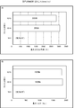
- ⁇ Third test> A third test was conducted on the two-flute drill 101 of the second embodiment in order to confirm the difference in cutting resistance from the conventional two-flute drill due to the difference in the shape of the gash portion 8.
- the gash portion 8 is the two-flute drill 101A of the second embodiment composed of the R portion 81 and the straight portion 82
- the gash portion 8 is the conventional two-flute drill 101B having only the R portion 81
- the gash portion 8 is straight.
- the maximum thrust load and the maximum torque during workpiece machining were measured for each of the conventional two-flute drills 101C having only the portion 82.
- the horizontal axis corresponds to the maximum thrust load during workpiece machining under the conditions of the third test
- the vertical axis corresponds to the two-flute drills 101A, 101B, and 101C, respectively.
- the horizontal axis corresponds to the maximum torque during machining under the conditions of the third test
- the vertical axis corresponds to the two-flute drills 101A, 101B, and 101C, respectively.
- the maximum thrust load and the maximum torque of the two-flute drill 101A were smaller than those of the conventional two-flute drills 101B and 101C. That is, the two-flute drill 101A has a smaller cutting resistance acting on the drill during machining than the conventional two-flute drills 101B and 101C. Therefore, it was obtained that the two-flute drill 101A can stabilize the cutting resistance lower than that of the conventional two-flute drills 101B and 101C.
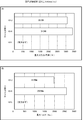
- ⁇ Fourth test> A fourth test was conducted on the two-flute drill 101 of the second embodiment in order to confirm the difference in cutting resistance according to the feed amount from the conventional two-flute drill due to the difference in the shape of the gash portion 8.
- 101K, and the conventional two-flute drills 101F, 101I, and 101L having only the straight portion 82 as the gash portion 8 were measured for changes in thrust load and torque during machining with time.
- the graphs of FIGS. 11 (A), 12 (A), and 13 (A) show the results of the fourth test by the two-flute drills 101D, 101G, and 101J of the second embodiment, respectively.
- the graphs of FIGS. 11 (B), 11 (C), 12 (B), and 13 (B) show the results of the fourth test using the conventional two-flute drills 101E, 101F, 101H, and 101K, respectively.
- the horizontal axis corresponds to time
- the vertical axis corresponds to the thrust load or torque during workpiece machining under the conditions of the fourth test.
- the vertical axis corresponds to the thrust load.
- Gulag the vertical axis corresponds to torque.
- the two-flute drills 101D, 101G, and 101J have the conventional two-flute drills 101E and 101F, respectively, regardless of the feed amount of the thrust load and the torque. , 101H, 101K. That is, regardless of the amount of feed, the thrust load and torque (cutting resistance) of the two-flute drills 101D, 101G, 101J are more conventional than the conventional two-flute drills 101E, 101F, 101H, 101K. Was more stable than.
- the vertical axis corresponds to the two-flute drills 101D, 101E, and 101F, respectively.
- the vertical axis corresponds to the two-flute drills 101G, 101H, and 101I, respectively.
- the vertical axis corresponds to the two-flute drills 101J, 101K, and 101L, respectively.
- the horizontal axis corresponds to the maximum thrust load during workpiece machining under the conditions of the fourth test.
- the horizontal axis corresponds to the maximum torque during machining under the conditions of the fourth test.
- the maximum thrust load and the maximum torque of the two-flute drills 101D, 101G, and 101J are the conventional two-flute drills 101E, 101F, 101H, respectively, regardless of the feed amount. It was smaller than 101K. That is, the two-flute drills 101D, 101G, and 101J have smaller cutting resistance acting on the drill during machining than the conventional two-flute drills 101E, 101F, 101H, and 101K, respectively. Therefore, it was obtained that the two-flute drills 101D, 101G, and 101J can stabilize the cutting resistance lower than that of the conventional two-flute drills 101E, 101F, 101H, and 101K, regardless of the feed amount. ..
Landscapes
- Engineering & Computer Science (AREA)
- Mechanical Engineering (AREA)
- Drilling Tools (AREA)
Priority Applications (6)
| Application Number | Priority Date | Filing Date | Title |
|---|---|---|---|
| KR1020207037908A KR102492629B1 (ko) | 2019-08-30 | 2019-08-30 | 드릴 |
| JP2020562786A JP7001844B2 (ja) | 2019-08-30 | 2019-08-30 | ドリル |
| US17/044,445 US11865626B2 (en) | 2019-08-30 | 2019-08-30 | Drill |
| EP19942824.4A EP4023378A4 (en) | 2019-08-30 | 2019-08-30 | FOREST |
| PCT/JP2019/034179 WO2021038841A1 (ja) | 2019-08-30 | 2019-08-30 | ドリル |
| CN201980042638.2A CN113015591B (zh) | 2019-08-30 | 2019-08-30 | 钻头 |
Applications Claiming Priority (1)
| Application Number | Priority Date | Filing Date | Title |
|---|---|---|---|
| PCT/JP2019/034179 WO2021038841A1 (ja) | 2019-08-30 | 2019-08-30 | ドリル |
Publications (1)
| Publication Number | Publication Date |
|---|---|
| WO2021038841A1 true WO2021038841A1 (ja) | 2021-03-04 |
Family
ID=74685327
Family Applications (1)
| Application Number | Title | Priority Date | Filing Date |
|---|---|---|---|
| PCT/JP2019/034179 WO2021038841A1 (ja) | 2019-08-30 | 2019-08-30 | ドリル |
Country Status (6)
| Country | Link |
|---|---|
| US (1) | US11865626B2 (zh) |
| EP (1) | EP4023378A4 (zh) |
| JP (1) | JP7001844B2 (zh) |
| KR (1) | KR102492629B1 (zh) |
| CN (1) | CN113015591B (zh) |
| WO (1) | WO2021038841A1 (zh) |
Cited By (5)
| Publication number | Priority date | Publication date | Assignee | Title |
|---|---|---|---|---|
| JP7095832B1 (ja) * | 2021-03-23 | 2022-07-05 | 住友電工ハードメタル株式会社 | ドリルヘッド、先端交換式ドリル及びドリル |
| WO2022208494A1 (en) * | 2021-03-29 | 2022-10-06 | Iscar Ltd. | Rotatable cutting head having tip portion with three radially extending cutting edges forming a rectilinear rotational profile |
| JPWO2022239045A1 (zh) * | 2021-05-10 | 2022-11-17 | ||
| JPWO2022239046A1 (zh) * | 2021-05-10 | 2022-11-17 | ||
| WO2023032180A1 (ja) * | 2021-09-06 | 2023-03-09 | オーエスジー株式会社 | ドリル |
Families Citing this family (1)
| Publication number | Priority date | Publication date | Assignee | Title |
|---|---|---|---|---|
| CN114453606B (zh) * | 2021-12-13 | 2023-12-29 | 浙江欣兴工具股份有限公司 | 一种刀头及分体式孔加工刀具 |
Citations (7)
| Publication number | Priority date | Publication date | Assignee | Title |
|---|---|---|---|---|
| JPH0529615U (ja) * | 1991-09-26 | 1993-04-20 | オーエスジー株式会社 | 難削材用硬質膜被覆ドリル |
| DE19602566A1 (de) * | 1996-01-25 | 1997-07-31 | Andre Woitschach Gmbh | Spiralbohrer |
| JP2006281407A (ja) * | 2005-04-04 | 2006-10-19 | Osg Corp | 非鉄金属加工用ドリル |
| JP2009148865A (ja) * | 2007-12-21 | 2009-07-09 | Omi Kogyo Co Ltd | ドリル |
| JP2016059999A (ja) | 2014-09-18 | 2016-04-25 | 住友電工ハードメタル株式会社 | ドリル |
| JP2017042879A (ja) * | 2015-08-27 | 2017-03-02 | 三菱マテリアル株式会社 | ドリル |
| WO2019088013A1 (ja) * | 2017-10-30 | 2019-05-09 | 京セラ株式会社 | ドリル及び切削加工物の製造方法 |
Family Cites Families (18)
| Publication number | Priority date | Publication date | Assignee | Title |
|---|---|---|---|---|
| JP2572128B2 (ja) * | 1989-05-16 | 1997-01-16 | 富士精工株式会社 | 高速高送り用バニシングドリルリーマ |
| JP3515168B2 (ja) * | 1994-05-13 | 2004-04-05 | 三菱マテリアル株式会社 | ドリル |
| JP3170203B2 (ja) * | 1996-08-19 | 2001-05-28 | オーエスジー株式会社 | ドリルの研削方法およびドリル |
| US5846035A (en) * | 1997-07-11 | 1998-12-08 | General Electric Company | Damage resistant drill |
| EP1275458A1 (en) * | 2001-07-10 | 2003-01-15 | Mitsubishi Materials Corporation | Drill |
| JPWO2008001412A1 (ja) * | 2006-06-23 | 2009-11-19 | オーエスジー株式会社 | ドリル |
| SE532432C2 (sv) * | 2008-05-09 | 2010-01-19 | Sandvik Intellectual Property | Borrkropp med primära och sekundära släppningsytor |
| DE102009025223A1 (de) * | 2009-06-08 | 2010-12-09 | MAPAL Fabrik für Präzisionswerkzeuge Dr. Kress KG | Bohrer |
| IL201486A (en) * | 2009-10-13 | 2015-05-31 | Iscar Ltd | drill |
| EP2774704B1 (en) * | 2011-11-04 | 2018-09-26 | OSG Corporation | Drill |
| WO2014208421A1 (ja) * | 2013-06-26 | 2014-12-31 | 京セラ株式会社 | ドリル |
| DE102013226697A1 (de) * | 2013-12-19 | 2015-06-25 | MAPAL Fabrik für Präzisionswerkzeuge Dr. Kress KG | Bohrer |
| JP6519971B2 (ja) * | 2014-01-16 | 2019-05-29 | 三菱日立ツール株式会社 | ドリル |
| KR102434577B1 (ko) * | 2015-05-08 | 2022-08-19 | 대구텍 유한책임회사 | 절삭 공구 |
| WO2017043129A1 (ja) * | 2015-09-09 | 2017-03-16 | 三菱マテリアル株式会社 | ドリル |
| JP2017164836A (ja) * | 2016-03-15 | 2017-09-21 | 住友電工ハードメタル株式会社 | ドリル |
| JP7078825B2 (ja) | 2017-07-27 | 2022-06-01 | 住友電工ハードメタル株式会社 | ドリル |
| JP6588625B2 (ja) | 2017-09-07 | 2019-10-09 | オーエスジー株式会社 | ドリル |
-
2019
- 2019-08-30 CN CN201980042638.2A patent/CN113015591B/zh active Active
- 2019-08-30 KR KR1020207037908A patent/KR102492629B1/ko active IP Right Grant
- 2019-08-30 EP EP19942824.4A patent/EP4023378A4/en active Pending
- 2019-08-30 WO PCT/JP2019/034179 patent/WO2021038841A1/ja unknown
- 2019-08-30 JP JP2020562786A patent/JP7001844B2/ja active Active
- 2019-08-30 US US17/044,445 patent/US11865626B2/en active Active
Patent Citations (7)
| Publication number | Priority date | Publication date | Assignee | Title |
|---|---|---|---|---|
| JPH0529615U (ja) * | 1991-09-26 | 1993-04-20 | オーエスジー株式会社 | 難削材用硬質膜被覆ドリル |
| DE19602566A1 (de) * | 1996-01-25 | 1997-07-31 | Andre Woitschach Gmbh | Spiralbohrer |
| JP2006281407A (ja) * | 2005-04-04 | 2006-10-19 | Osg Corp | 非鉄金属加工用ドリル |
| JP2009148865A (ja) * | 2007-12-21 | 2009-07-09 | Omi Kogyo Co Ltd | ドリル |
| JP2016059999A (ja) | 2014-09-18 | 2016-04-25 | 住友電工ハードメタル株式会社 | ドリル |
| JP2017042879A (ja) * | 2015-08-27 | 2017-03-02 | 三菱マテリアル株式会社 | ドリル |
| WO2019088013A1 (ja) * | 2017-10-30 | 2019-05-09 | 京セラ株式会社 | ドリル及び切削加工物の製造方法 |
Non-Patent Citations (1)
| Title |
|---|
| See also references of EP4023378A4 |
Cited By (9)
| Publication number | Priority date | Publication date | Assignee | Title |
|---|---|---|---|---|
| JP7095832B1 (ja) * | 2021-03-23 | 2022-07-05 | 住友電工ハードメタル株式会社 | ドリルヘッド、先端交換式ドリル及びドリル |
| WO2022208494A1 (en) * | 2021-03-29 | 2022-10-06 | Iscar Ltd. | Rotatable cutting head having tip portion with three radially extending cutting edges forming a rectilinear rotational profile |
| JPWO2022239045A1 (zh) * | 2021-05-10 | 2022-11-17 | ||
| JPWO2022239046A1 (zh) * | 2021-05-10 | 2022-11-17 | ||
| WO2022239045A1 (ja) * | 2021-05-10 | 2022-11-17 | オーエスジー株式会社 | ドリル |
| WO2022239046A1 (ja) * | 2021-05-10 | 2022-11-17 | オーエスジー株式会社 | ドリル |
| JP7314419B2 (ja) | 2021-05-10 | 2023-07-25 | オーエスジー株式会社 | ドリル |
| JP7314418B2 (ja) | 2021-05-10 | 2023-07-25 | オーエスジー株式会社 | ドリル |
| WO2023032180A1 (ja) * | 2021-09-06 | 2023-03-09 | オーエスジー株式会社 | ドリル |
Also Published As
| Publication number | Publication date |
|---|---|
| EP4023378A4 (en) | 2023-05-24 |
| KR102492629B1 (ko) | 2023-01-30 |
| CN113015591B (zh) | 2024-04-30 |
| US20210229190A1 (en) | 2021-07-29 |
| JPWO2021038841A1 (ja) | 2021-09-13 |
| CN113015591A (zh) | 2021-06-22 |
| JP7001844B2 (ja) | 2022-01-20 |
| KR20210027294A (ko) | 2021-03-10 |
| US11865626B2 (en) | 2024-01-09 |
| EP4023378A1 (en) | 2022-07-06 |
Similar Documents
| Publication | Publication Date | Title |
|---|---|---|
| JP7001844B2 (ja) | ドリル | |
| JP6252717B1 (ja) | 小径ドリル | |
| JP5816364B2 (ja) | 3枚刃ドリル | |
| WO2010146839A1 (ja) | クーラント穴付きドリル | |
| JP5927671B2 (ja) | 小径ドリル | |
| JP2008137125A (ja) | ドリル | |
| US20180056403A1 (en) | Drill | |
| WO2019044791A1 (ja) | テーパーリーマ | |
| JP4699526B2 (ja) | ドリル | |
| KR20200096983A (ko) | 드릴 | |
| JP2020023051A (ja) | ドリル | |
| JP4839129B2 (ja) | ドリル | |
| JP7375329B2 (ja) | ドリル | |
| JP2006281407A (ja) | 非鉄金属加工用ドリル | |
| JP6902284B2 (ja) | 切削工具 | |
| JP2005177891A (ja) | ドリル | |
| JP2023050297A (ja) | ドリル | |
| JP4954044B2 (ja) | ドリル | |
| KR102389301B1 (ko) | 탄소 섬유 강화 플라스틱(cfrp) 가공용 드릴 | |
| JP2003039218A (ja) | 深穴用ドリル | |
| WO2023210572A1 (ja) | ドリル | |
| JP2005186247A (ja) | ツイストドリル | |
| JPH0890323A (ja) | ドリル | |
| JP2009101452A (ja) | ドリル | |
| JP2011125941A (ja) | ドリル |
Legal Events
| Date | Code | Title | Description |
|---|---|---|---|
| ENP | Entry into the national phase |
Ref document number: 2020562786 Country of ref document: JP Kind code of ref document: A |
|
| 121 | Ep: the epo has been informed by wipo that ep was designated in this application |
Ref document number: 19942824 Country of ref document: EP Kind code of ref document: A1 |
|
| NENP | Non-entry into the national phase |
Ref country code: DE |
|
| ENP | Entry into the national phase |
Ref document number: 2019942824 Country of ref document: EP Effective date: 20220330 |