WO2021033642A1 - 内視鏡 - Google Patents
内視鏡 Download PDFInfo
- Publication number
- WO2021033642A1 WO2021033642A1 PCT/JP2020/030874 JP2020030874W WO2021033642A1 WO 2021033642 A1 WO2021033642 A1 WO 2021033642A1 JP 2020030874 W JP2020030874 W JP 2020030874W WO 2021033642 A1 WO2021033642 A1 WO 2021033642A1
- Authority
- WO
- WIPO (PCT)
- Prior art keywords
- tip
- cap
- cantilever
- stopper
- main body
- Prior art date
- Legal status (The legal status is an assumption and is not a legal conclusion. Google has not performed a legal analysis and makes no representation as to the accuracy of the status listed.)
- Ceased
Links
Images




Classifications
-
- A—HUMAN NECESSITIES
- A61—MEDICAL OR VETERINARY SCIENCE; HYGIENE
- A61B—DIAGNOSIS; SURGERY; IDENTIFICATION
- A61B1/00—Instruments for performing medical examinations of the interior of cavities or tubes of the body by visual or photographical inspection, e.g. endoscopes; Illuminating arrangements therefor
- A61B1/00131—Accessories for endoscopes
- A61B1/00137—End pieces at either end of the endoscope, e.g. caps, seals or forceps plugs
-
- A—HUMAN NECESSITIES
- A61—MEDICAL OR VETERINARY SCIENCE; HYGIENE
- A61B—DIAGNOSIS; SURGERY; IDENTIFICATION
- A61B1/00—Instruments for performing medical examinations of the interior of cavities or tubes of the body by visual or photographical inspection, e.g. endoscopes; Illuminating arrangements therefor
- A61B1/012—Instruments for performing medical examinations of the interior of cavities or tubes of the body by visual or photographical inspection, e.g. endoscopes; Illuminating arrangements therefor characterised by internal passages or accessories therefor
- A61B1/018—Instruments for performing medical examinations of the interior of cavities or tubes of the body by visual or photographical inspection, e.g. endoscopes; Illuminating arrangements therefor characterised by internal passages or accessories therefor for receiving instruments
-
- A—HUMAN NECESSITIES
- A61—MEDICAL OR VETERINARY SCIENCE; HYGIENE
- A61B—DIAGNOSIS; SURGERY; IDENTIFICATION
- A61B1/00—Instruments for performing medical examinations of the interior of cavities or tubes of the body by visual or photographical inspection, e.g. endoscopes; Illuminating arrangements therefor
- A61B1/273—Instruments for performing medical examinations of the interior of cavities or tubes of the body by visual or photographical inspection, e.g. endoscopes; Illuminating arrangements therefor for the upper alimentary canal, e.g. oesophagoscopes, gastroscopes
-
- A—HUMAN NECESSITIES
- A61—MEDICAL OR VETERINARY SCIENCE; HYGIENE
- A61B—DIAGNOSIS; SURGERY; IDENTIFICATION
- A61B1/00—Instruments for performing medical examinations of the interior of cavities or tubes of the body by visual or photographical inspection, e.g. endoscopes; Illuminating arrangements therefor
- A61B1/00064—Constructional details of the endoscope body
-
- A—HUMAN NECESSITIES
- A61—MEDICAL OR VETERINARY SCIENCE; HYGIENE
- A61B—DIAGNOSIS; SURGERY; IDENTIFICATION
- A61B1/00—Instruments for performing medical examinations of the interior of cavities or tubes of the body by visual or photographical inspection, e.g. endoscopes; Illuminating arrangements therefor
- A61B1/00064—Constructional details of the endoscope body
- A61B1/00071—Insertion part of the endoscope body
- A61B1/0008—Insertion part of the endoscope body characterised by distal tip features
- A61B1/00098—Deflecting means for inserted tools
-
- A—HUMAN NECESSITIES
- A61—MEDICAL OR VETERINARY SCIENCE; HYGIENE
- A61B—DIAGNOSIS; SURGERY; IDENTIFICATION
- A61B1/00—Instruments for performing medical examinations of the interior of cavities or tubes of the body by visual or photographical inspection, e.g. endoscopes; Illuminating arrangements therefor
- A61B1/00064—Constructional details of the endoscope body
- A61B1/00071—Insertion part of the endoscope body
- A61B1/0008—Insertion part of the endoscope body characterised by distal tip features
- A61B1/00101—Insertion part of the endoscope body characterised by distal tip features the distal tip features being detachable
-
- A—HUMAN NECESSITIES
- A61—MEDICAL OR VETERINARY SCIENCE; HYGIENE
- A61B—DIAGNOSIS; SURGERY; IDENTIFICATION
- A61B1/00—Instruments for performing medical examinations of the interior of cavities or tubes of the body by visual or photographical inspection, e.g. endoscopes; Illuminating arrangements therefor
- A61B1/00131—Accessories for endoscopes
-
- A—HUMAN NECESSITIES
- A61—MEDICAL OR VETERINARY SCIENCE; HYGIENE
- A61B—DIAGNOSIS; SURGERY; IDENTIFICATION
- A61B1/00—Instruments for performing medical examinations of the interior of cavities or tubes of the body by visual or photographical inspection, e.g. endoscopes; Illuminating arrangements therefor
- A61B1/005—Flexible endoscopes
- A61B1/0051—Flexible endoscopes with controlled bending of insertion part
-
- A—HUMAN NECESSITIES
- A61—MEDICAL OR VETERINARY SCIENCE; HYGIENE
- A61B—DIAGNOSIS; SURGERY; IDENTIFICATION
- A61B1/00—Instruments for performing medical examinations of the interior of cavities or tubes of the body by visual or photographical inspection, e.g. endoscopes; Illuminating arrangements therefor
- A61B1/012—Instruments for performing medical examinations of the interior of cavities or tubes of the body by visual or photographical inspection, e.g. endoscopes; Illuminating arrangements therefor characterised by internal passages or accessories therefor
- A61B1/015—Control of fluid supply or evacuation
-
- A—HUMAN NECESSITIES
- A61—MEDICAL OR VETERINARY SCIENCE; HYGIENE
- A61B—DIAGNOSIS; SURGERY; IDENTIFICATION
- A61B1/00—Instruments for performing medical examinations of the interior of cavities or tubes of the body by visual or photographical inspection, e.g. endoscopes; Illuminating arrangements therefor
- A61B1/04—Instruments for performing medical examinations of the interior of cavities or tubes of the body by visual or photographical inspection, e.g. endoscopes; Illuminating arrangements therefor combined with photographic or television appliances
-
- A—HUMAN NECESSITIES
- A61—MEDICAL OR VETERINARY SCIENCE; HYGIENE
- A61B—DIAGNOSIS; SURGERY; IDENTIFICATION
- A61B1/00—Instruments for performing medical examinations of the interior of cavities or tubes of the body by visual or photographical inspection, e.g. endoscopes; Illuminating arrangements therefor
- A61B1/06—Instruments for performing medical examinations of the interior of cavities or tubes of the body by visual or photographical inspection, e.g. endoscopes; Illuminating arrangements therefor with illuminating arrangements
- A61B1/0661—Endoscope light sources
-
- A—HUMAN NECESSITIES
- A61—MEDICAL OR VETERINARY SCIENCE; HYGIENE
- A61B—DIAGNOSIS; SURGERY; IDENTIFICATION
- A61B1/00—Instruments for performing medical examinations of the interior of cavities or tubes of the body by visual or photographical inspection, e.g. endoscopes; Illuminating arrangements therefor
- A61B1/12—Instruments for performing medical examinations of the interior of cavities or tubes of the body by visual or photographical inspection, e.g. endoscopes; Illuminating arrangements therefor with cooling or rinsing arrangements
- A61B1/126—Instruments for performing medical examinations of the interior of cavities or tubes of the body by visual or photographical inspection, e.g. endoscopes; Illuminating arrangements therefor with cooling or rinsing arrangements provided with means for cleaning in-use
Definitions
- the present invention relates to an endoscope, and particularly relates to an endoscope provided with a stand on the tip side of an insertion portion to change the direction in which the treatment tool is taken out.
- various treatment tools are introduced from the treatment tool introduction port provided in the operation part, and this treatment tool is taken out from the treatment tool outlet opened at the tip of the insertion part and used for treatment.
- a treatment tool such as a guide wire or a contrast tube is used.
- Treatment tools such as puncture needles are used in ultrasonic endoscopes.
- treatment tools such as forceps or snares are used.
- Such a treatment tool needs to change the lead-out direction at the tip in order to treat a desired position in the subject. For this reason, the tip body of the tip is provided with a stand for changing the direction in which the treatment tool is taken out.
- the endoscope is provided with a treatment tool standing mechanism that displaces the posture of the standing table between the standing position and the lying position.
- a cap can be detachably attached to the tip body.
- the endoscope of Patent Document 1 has an uneven portion that can be engaged with the cap and the tip main body, and the cap and the tip main body are positioned and fixed by engaging the uneven portion. By crushing the cap in the vertical direction, the engagement of the uneven portion is released.
- the endoscope of Patent Document 2 is a side-viewing type endoscope in which a side portion of the tip portion is partially cut out and a notched surface is provided. By engaging the engaging groove provided in the region on the base end side of the notch surface with the engaging projection of the cap, the displacement of the cap is prevented.
- the cap is loaded, for example, when the treatment tool is erected or when the guide wire is pulled out and fixed.
- the cap is required to be less deformed by the load.
- the cap is required to be deformed by fingers when it is removed.
- the present invention has been made in view of such circumstances, and an object of the present invention is to provide an endoscope provided with a cap that can be easily removed while suppressing deformation due to a load.
- the endoscope according to the first aspect of the present invention is located at the operation portion provided with the operation member, the insertion portion provided on the tip side of the operation portion and inserted into the subject, and the tip of the insertion portion.
- Centering on the tip body which has a treatment tool outlet and is formed with a stand-up storage space that communicates with the treatment tool outlet, and a rotation axis that is arranged in the stand-up space and is orthogonal to the long axis direction of the insertion part.
- a stand that can rotate between the lodging position and the standing position, and a cap that is detachably attached to the tip body and covers the standing space, and is orthogonal to the long axis direction and the rotation axis of the insertion part.
- a cap having a wall portion defining an open window is provided, and the cap is an elastically flexing and deformable cantilever formed on a wall portion on at least one side facing the opening window.
- the cantilever has a fixed end and a free end, the cantilever includes a stoppered portion provided at the free end, and the tip body is stoppered on the side facing the cantilever.
- the stoppered portion is removable from the stopper portion, including the stopper portion that engages with the portion. According to the first aspect, the cap can be easily removed and deformation due to a load can be prevented.
- the cantilever includes a pressing portion located between the fixed end and the free end and separated from the tip body, and the pressing portion and the free end of the cantilever. It has a fulcrum portion at an opposite position between the two, and by pressing the pressing portion toward the tip body, the cantilever is flexed and deformed with the fulcrum portion as the fulcrum, and the stopper portion and the stoppered portion are formed. Disengage.
- the fulcrum portion is arranged from the position of the stopper portion to the tip end side of the tip portion main body, and the fixed end of the cantilever is arranged on the tip end side of the tip portion main body from the position of the fulcrum portion. Will be done.
- the stopper portion is wider than the other portion of the cantilever piece, the stopper portion is narrower than the stopper portion, and the groove portion is wider than the other portion of the cantilever piece. It is composed of members.
- the fulcrum portion is arranged on the proximal end side of the tip portion main body from the position of the stopper portion, and the fixed end of the cantilever is located on the proximal end side of the tip portion main body from the position of the fulcrum portion. Is placed in.
- the cap includes a notch orthogonal to the cantilever and a thin portion parallel to the cantilever in the wall portion on which the cantilever is formed.
- the stopper portion has an inclined surface that extends outward from the tip end side to the base end side of the tip end body.
- a contact member is provided at a position facing the treatment tool guide surface of the standing table.
- the cap and the contact member are formed of an integrally molded body.
- the stand and the rotating shaft are attached to the cap.
- the endoscope of the present invention it is possible to provide an endoscope having a cap that can be easily removed by suppressing deformation due to a load.
- FIG. 1 is a configuration diagram of an endoscope system including an endoscope according to the first embodiment.
- FIG. 2 is an enlarged perspective view of the tip portion.
- FIG. 3 is a perspective view of the tip main body of the first embodiment shown in FIG.
- FIG. 4 is a perspective view of the cap shown in FIG.
- FIG. 5 is a cross-sectional view including the cap-side claw portion shown in FIG.
- FIG. 6 is a perspective view of the tip portion of the first embodiment as viewed from the X (+) side.
- FIG. 7 is an assembled perspective view of the tip portion shown in FIG.
- FIG. 8 is a partially enlarged perspective view of the tip portion.
- FIG. 9 is an explanatory view illustrating the operation of attaching and detaching the cap and the tip body of the first embodiment.
- FIG. 9 is an explanatory view illustrating the operation of attaching and detaching the cap and the tip body of the first embodiment.
- FIG. 10 is a diagram showing a state in which the treatment tool and the guide wire are erected by the erection stand.
- FIG. 11 is a perspective view of the tip portion of the second embodiment as viewed from the X (+) side.
- FIG. 12 is an assembled perspective view of the tip portion shown in FIG.
- FIG. 13 is an explanatory view illustrating the operation of attaching and detaching the cap and the tip body of the second embodiment.
- FIG. 14 is a side view of the third embodiment as viewed from the X (+) side.
- FIG. 15 is a cross-sectional view taken along the line 15-15 of FIG.
- FIG. 1 is a block diagram of an endoscope system 12 including an endoscope 10 according to an embodiment of the present invention.
- the endoscope system 12 includes an endoscope 10, a processor device 14, a light source device 16, and a display 18.
- the endoscope 10 includes an operation unit 22 provided with a standing operation lever 20 which is an operation member, and an insertion unit 24 provided on the tip end side of the operation unit 22 and inserted into a subject.
- the insertion portion 24 has a long axis direction Ax from the base end to the tip end, and includes a soft portion 26, a curved portion 28, and a tip end portion 30 in this order from the base end to the tip end.
- the detailed configuration of the tip portion 30 will be described later, but first, a schematic configuration of the tip portion 30 will be described.
- FIG. 2 is an enlarged perspective view of the tip portion 30.
- the endoscope 10 of the embodiment (see FIG. 1) is a lateral endoscope used as, for example, a duodenal endoscope, and the tip portion 30 of FIG. 2 has a configuration of a lateral endoscope. ..
- FIG. 3 is a perspective view of the tip portion main body 32 constituting the tip portion 30.
- FIG. 4 is a perspective view of the cap 34 constituting the tip portion 30.
- the tip portion 30 has a tip portion main body 32 and a cap 34.
- the cap 34 is detachably attached to the tip body 32.
- the tip body 32 is provided on the tip side of the insertion portion 24 (see FIG. 1).
- the tip body 32 is provided with an upright stand 36 having a treatment tool guide surface 36A, which will be described later. 2 and 4 show a state in which the standing table 36 is positioned in the lodging position.
- FIG. 2 shows various contents arranged inside the insertion portion 24 of the endoscope 10 (see FIG. 1).
- the standing table 36 and the standing operation wire 40 (hereinafter,) for performing an operation of changing the lead-out direction of the tip of the treatment tool derived from the tip main body 32 with respect to the tip of the treatment tool (not shown).
- Wire 40) and an air supply / water supply tube 42 are provided.
- the wire 40 is directly connected to the upright stand 36.
- a treatment tool channel 38 leading to the tip body 32 and an angle wire for performing an operation of changing the bending direction of the curved portion 28 (see FIG. 1).
- a signal cable for transmitting an image signal and contents such as a light guide for transmitting illumination light are also provided.
- a three-dimensional Cartesian coordinate system in the three-axis directions (X-axis direction, Y-axis direction, Z-axis direction) will be described. That is, when the tip portion 30 is viewed from the operating portion 22 and the direction in which the treatment tool (not shown) is derived by the standing table 36 is the upward direction, the upward direction is the Z (+) direction and the opposite direction. Let a certain downward direction be the Z (-) direction. Further, the right direction at that time is the X (+) direction, and the left direction is the X ( ⁇ ) direction.
- the front direction (the direction toward the tip end side in the long axis direction Ax direction of the insertion portion 24) at that time is the Y (+) direction
- the rear direction (the base end side in the long axis direction Ax direction of the insertion portion 24).
- the direction) is the Y (-) direction.
- the Y-axis direction including the Y (+) direction and the Y ( ⁇ ) direction is parallel to the direction of the major axis direction Ax of the insertion portion 24.
- the Z-axis direction is a direction orthogonal to the long-axis direction Ax.
- the X-axis direction is a direction orthogonal to the Z-axis direction.
- the operation unit 22 is configured to have a substantially cylindrical shape as a whole.
- the operation unit 22 has an operation unit main body 46 in which the standing operation lever 20 is rotatably provided, and a grip portion 48 connected to the operation unit main body 46.
- the base end portion of the insertion portion 24 is provided on the tip end side of the grip portion 48 via the breakthrough pipe 50.
- the grip portion 48 is a portion that is gripped by the operator when operating the endoscope 10.
- the operation unit main body 46 is provided with a universal cable 52.
- a light source connector 54 is provided on the tip end side of the universal cable 52.
- An electric connector 56 is branched and provided in the light source connector 54. Then, the electric connector 56 is connected to the processor device 14, and the light source connector 54 is connected to the light source device 16.
- the air supply / water supply button 57 and the suction button 59 are arranged side by side on the operation unit main body 46.
- air and water are supplied to the air supply / water supply tube 42 of FIG. 2, and air and water can be ejected from the air supply / water supply nozzle 58 provided in the tip main body 32.
- the air supply / water supply button 57 in FIG. 1 is a two-step operation. Air is supplied to the air supply / water supply tube 42 by a one-step operation. Water is supplied to the air supply water supply tube 42 by a two-step operation.
- body fluid such as blood is discharged from the suction port that also serves as the treatment tool outlet 60 provided in the tip body 32 of FIG. 2 via the treatment tool channel 38 (see FIG. 6). Can be sucked.
- a pair of angle knobs 62, 62 for bending the curved portion 28 are arranged on the operation unit main body 46.
- the pair of angle knobs 62, 62 are provided coaxially and rotatably.
- the standing operation lever 20 is rotatably provided coaxially with the angle knobs 62 and 62.
- the standing operation lever 20 is rotationally operated by the operator who grips the grip portion 48.
- the wire 40 of FIG. 2 is pushed and pulled in conjunction with the rotation operation of the standing operation lever 20.
- the posture of the standing table 36 connected to the tip end side of the wire 40 is changed between the lodging position shown in FIG. 2 and the standing position (not shown).
- the grip portion 48 of the operation portion 22 includes a treatment tool introduction port 64 into which the treatment tool is introduced.
- the treatment tool (not shown) introduced from the treatment tool introduction port 64 with the tip portion at the head is inserted into the treatment tool channel 38 (not shown) and is external from the treatment tool outlet 60 provided in the tip portion main body 32. Derived to.
- the soft portion 26 of the insertion portion 24 has a spiral tube (not shown) formed by spirally winding a thin metal strip having elasticity.
- the flexible portion 26 is formed by covering the outside of the spiral tube with a tubular net body woven with a metal wire, and covering the outer peripheral surface of the net body with an outer skin made of resin.
- the curved portion 28 of the insertion portion 24 has a structure in which a plurality of angle rings (not shown) are rotatably connected to each other.
- the curved portion 28 is formed by covering the outer periphery of the structure with a tubular net body woven with a metal wire, and covering the outer peripheral surface of the net body with a rubber tubular outer skin.
- four angle wires are arranged from the curved portion 28 configured in this way to the angle knobs 62 and 62, and these angle wires are released by the rotation operation of the angle knobs 62 and 62.
- the curved portion 28 is curved vertically and horizontally by the push-pull operation.
- the endoscope 10 of the embodiment is a lateral endoscope used as, for example, a duodenal endoscope, and the insertion portion 24 is inserted into the subject through the oral cavity.
- the insertion portion 24 is inserted from the esophagus through the stomach to the duodenum, and a predetermined examination or treatment is performed.
- the treatment tools used in the endoscope 10 of the embodiment include biopsy forceps having a cup capable of collecting biological tissue at the tip, an EST (Endoscopic Sphincterotomy) knife, or an EST (endoscopic nipple incision) knife.
- a treatment tool such as a contrast tube can be exemplified.
- the tip portion 30 includes a tip portion main body 32 and a cap 34 that is detachably attached to the tip portion main body 32.
- the tip main body 32 has a partition wall 68 projecting in the Y (+) direction.
- the standing table accommodating space 66 is formed by the partition wall 68 of the tip body 32 and the wall portion 34B of the cap 34.
- the standing table accommodating space 66 is arranged at a position in the X (+) direction of the partition wall 68 and in the Y (+) direction of the treatment tool outlet 60.
- the tip body 32 is made of a metal material having corrosion resistance.
- an illumination window 74 and an observation window 76 are arranged adjacent to each other in the Y direction on the upper surface 68A on the Z (+) side of the partition wall 68.
- the observation window 76 makes it possible to observe the visual field region in the Z (+) direction.
- the air supply / water supply nozzle 58 is provided on the tip main body 32 toward the observation window 76.
- the observation window 76 is cleaned by air and water ejected from the air supply / water supply nozzle 58.
- the partition wall 68 includes an optical system accommodating chamber 72 inside.
- the optical system accommodating chamber 72 accommodates a lighting unit (not shown) and a photographing unit (not shown).
- the illumination unit includes an illumination lens (not shown) arranged on the side of the optical system accommodation chamber 72 of the illumination window 74, and a light guide (not shown) arranged so that the tip surface faces the illumination lens.
- the light guide is arranged on the universal cable 52 from the insertion portion 24 of the endoscope 10 (see FIG. 1) via the operation portion 22.
- the base end of the light guide is connected to the light source connector 54.
- the light source connector 54 When the light source connector 54 is connected to the light source device 16, the irradiation light from the light source device 16 is transmitted to the illumination lens via the light guide.
- the irradiation light is applied to the visual field region existing in the Z (+) direction from the illumination window 74.
- the photographing unit includes a photographing optical system (not shown) arranged inside the observation window 76, and a CMOS (complementary metal oxide semiconductor) type or CCD (charge coupled device) type image sensor (not shown). ..
- the tip of a signal cable (not shown) is connected to the image sensor.
- the signal cable is arranged on the universal cable 52 from the insertion portion 24 of the endoscope 10 (see FIG. 1) via the operation portion 22.
- the base end of the signal cable is connected to the electrical connector 56.
- the electric connector 56 is connected to the processor device 14
- the imaging signal of the subject image obtained by the photographing unit is transmitted to the processor device 14 via the signal cable.
- the image pickup signal is image-processed by the processor device 14 and then displayed as a subject image on the display 18.
- the tip body 32 has a stopper 63 on the base end side.
- the stopper portion 63 engages with a stoppered portion provided on a surface on the base end side of the contact member 37, which will be described later.
- the tip body 32 is provided with a through hole 61 for inserting a wire 40 (not shown).
- the cap 34 includes a wall portion 34B formed in a substantially tubular shape with the tip side sealed.
- a substantially rectangular opening window 34A is defined by a wall portion 34B on a part of the outer peripheral surface of the cap 34.
- a bearing 34D extending in the Y (+) direction (direction extending in the major axis direction Ax) is formed inside the cap 34.
- the bearing 34D has a plate shape having a height in the Z (+) direction.
- the cap 34 is made of an elastic material, for example, a rubber material such as fluororubber or silicone rubber, and a resin material such as polysulfone or polycarbonate.
- the rotating shaft 36B of the upright stand 36 is supported by a through hole (not shown) of the bearing 34D.
- the rotating shaft 36B is a rod-shaped member having a length in the X-axis direction orthogonal to the bearing 34D.
- the standing table 36 is rotatable between the lying position and the standing position about the rotation shaft 36B.
- the wire 40 is connected to the upright stand 36.
- the wire 40 is attached at a position adjacent to the treatment tool guide surface 36A on the tip side of the upright stand 36 opposite to the side on which the rotating shaft 36B is formed.
- the standing table 36 is attached to the cap 34 shown in FIG. 4, and is used as a whole as a cap 34 with the standing table 36.
- the wire 40 is connected to the upright stand 36.
- the opening window 34A of the cap 34 is opened in the Z (+) direction. That is, the opening direction of the opening window 34A of the cap 34 is orthogonal to the direction of the major axis direction Ax of the insertion portion and is orthogonal to the axial direction (X-axis direction) of the rotating shaft 36B.
- the cap 34 is an integrally molded body in which the wall portion 34B and the contact member 37 are integrally molded.
- the contact member 37 is made of a resin material.
- the contact member 37 is arranged on the side of the base end of the opening window 34A.
- the abutting member 37 projects toward the Y (+) direction as a whole.
- the integral molding means that the product (cap 34 and the contact member 37) is integrally molded at the same time as the members are joined without using adhesion or mechanical joining.
- the cap 34 including the wire 40 and the upright stand 36 is removed from the tip main body 32 and is discarded as a disposable, for example.
- the cap 34 When the cap 34 is attached to the tip main body 32, as shown in FIG. 2, the cap 34 forms an upright stand accommodating space 66, and the opening window 34A is opened in the Z (+) direction.
- the treatment tool outlet 60 of the tip main body 32 is communicated with the opening window 34A via the standing table accommodating space 66.
- the abutting member 37 is located in the Z (+) direction with respect to the treatment tool outlet 60, and is provided at a position facing the treatment tool guide surface 36A when the standing table 36 is in the standing position.
- the tip 30 is provided with a fall prevention mechanism in order to prevent the cap 34 from falling off from the tip body 32 along the Y (+) direction.
- the cap 34 has a cap side claw portion 34C (see FIGS. 2 and 4) provided on one of the two wall portions 34B sandwiching the opening window 34A, and the tip portion main body 32 has a cap side. It is composed of a main body side claw portion 78 (see FIG. 3) provided at a position facing the claw portion 34C.
- the cap side claw portion 34C is formed by cutting the cap 34 into a U shape.
- the U-shaped notch penetrates the outside and inside of the cap 34.
- the U-shaped notch is a U-shape that opens in the Y (-) direction, and the cap-side claw portion 34C is in a so-called cantilever state in which the base end side of the cap-side claw portion 34C is connected to the cap 34. It becomes.
- the tip side of the cap-side claw portion 34C can be displaced in the X (+) direction and the X ( ⁇ ) direction with the connection position with the cap 34 as a fulcrum.
- the main body side claw portion 78 is a protrusion formed on the tip main body 32 and projecting in the X ( ⁇ ) direction.
- FIG. 5 is a cross-sectional view including the cap side claw portion 34C shown in FIG.
- the cap 34 and the tip body 32 are attached and detached by relatively moving along the Y-axis direction.
- the claw portion 78 on the main body side has a substantially trapezoidal shape in cross-sectional view.
- the main body side claw portion 78 has an inclined surface that extends outward from the tip end side to the base end side of the tip end main body 32 on the tip end side.
- the main body side claw portion 78 has an orthogonal plane orthogonal to the Y-axis direction on the side of the base end thereof.
- the cap-side claw portion 34C has a shape that bends inward on the side of the tip thereof, and the tip is formed by an orthogonal plane orthogonal to the Y-axis direction.
- cap 34 is attached to the tip body 32.
- the tip body 32 is fixed in order to facilitate understanding.
- the cap 34 When the cap 34 is attached to the tip body 32, the cap 34 is moved from Y (+) to Y (-). The bent portion of the cap-side claw portion 34C comes into contact with the inclined surface of the main body-side claw portion 78. Further, when the cap 34 is moved in the Y ( ⁇ ) direction, the cap side claw portion 34C moves along the inclined surface of the main body side claw portion 78, and finally gets over the main body side claw portion 78.
- the tip of the cap side claw portion 34C and the base end of the main body side claw portion 78 are orthogonal planes, respectively.
- the resistance force of the cap-side claw portion 34C overcoming the main body-side claw portion 78 increases.
- the cap 34 is prevented from falling off from the tip body 32.
- FIG. 6 is a perspective view of the tip portion 30 as seen from the X (+) side
- FIG. 7 is an assembled perspective view of the tip portion 30.
- FIG. 8 is a partially enlarged view of the tip portion 30.
- FIG. 9 is a diagram for explaining attachment / detachment of the cap. Wire 40 is not shown in FIG.
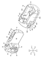
- the cap 34 is provided on one side of the two wall portions 34B arranged in the X (+) direction and the X ( ⁇ ) direction with the opening window 34A interposed therebetween. It has a cantilever piece 90.
- the cantilever piece 90 is formed by providing a notch 91 in the cap 34. The notch 91 penetrates the outside and the inside of the cap 34.
- the cantilever 90 has a fixed end 90A extending in the Y-axis direction and connected to the cap 34, and a free end 90B not connected to the cap 34.
- the fixed end 90A is located on the tip side (Y (+) direction) of the free end 90B. Since the free end 90B is not connected to the cap 34, it can be displaced in the X (+) direction and the X ( ⁇ ) direction. It is movable. Since the cantilever piece 90 is formed by the notch 91 of the cap 34, the cantilever piece 90 is made of the same material as the cap 34.
- a stoppered portion 90C is provided on the free end 90B of the cantilever piece 90.
- the stoppered portion 90C is wider than the other portion of the cantilever piece 90.
- the cantilever 90 has a T shape as a whole.
- the stoppered portion 90C can be displaced in the X (+) direction and the X ( ⁇ ) direction in succession with the free end 90B.
- the cantilever piece 90 has a pressing portion 90D located between the fixed end 90A and the free end 90B and separated from the tip main body 32.
- a pressing force from a human finger (not shown) is applied to the pressing portion 90D, the pressing portion 90D elastically bends and deforms toward the X ( ⁇ ) side.
- the cantilever piece 90 is not limited to the T-shape as long as it has a shape that bends and deforms due to pressing pressure by a human finger.
- the shape of the cantilever piece 90 is determined in consideration of the length, thickness, width and the like.
- the length of the cantilever 90 is the distance along the Y-axis direction
- the thickness of the cantilever 90 is the distance between the outer surface and the inner surface of the cantilever 90
- the width of the cantilever 90 is the length. It is the distance in the direction orthogonal to the thickness.
- the tip main body 32 has two stoppers 80 and a fulcrum 82 located between the stoppers 80 on the side facing the cantilever 90.
- the two stoppers 80 define the groove 84.
- the two stopper portions 80 have groove portions 84 that are narrower than the width of the stoppered portion 90C and wider than the width of the other portion of the cantilever 90 (the portion other than the stoppered portion 90C). It is placed at the constituent positions.
- the stopper portion 80 and the stopper portion 90C are engaged with each other depending on the size of the distance between the stopper portions 80, the width of the stopper portion 90C, and the width of the portion other than the stopper portion 90C.
- the cap side claw portion 34C and the main body side claw portion 78 may not be provided.
- FIG. 9-1 is a cross-sectional view taken along line 9-1 of FIG. 8
- 9-2 is a cross-sectional view taken along line 9-2 of FIG.
- the cantilever piece 90 When the cap 34 is attached to the tip body 32, the cantilever piece 90 is not bent and deformed as shown by the alternate long and short dash line of 9-1. In the embodiment, the cantilever 90 is substantially in contact with the fulcrum 82. The pressing portion 90D of the cantilever piece 90 is separated from the tip portion main body 32. Separation is a state in which the pressing portion 90D is not in contact with the tip portion main body 32.
- the stopper 80 and the stoppered portion 90C shown by the alternate long and short dash line are engaged.
- the stopper portion 80 has an inclined surface 80A.
- the inclined surface 80A is an inclined surface that extends outward from the tip end side of the tip end body 32 toward the base end side.
- the stopper portion 80 has an orthogonal plane 80B orthogonal to the Y-axis direction on the base end side.
- the fulcrum portion 82 is moved from the position of the orthogonal surface 80B (engagement surface) of the stopper portion 80 to the tip side (Y (+) direction) of the tip portion main body 32. Be placed.
- the fixed end 90A of the cantilever piece 90 is arranged closer to the tip of the tip body 32 than the position of the fulcrum 82.
- the cap 34 When the cap 34 is attached to the tip body 32, the cap 34 is moved from Y (+) to Y (-). The stoppered portion 90C comes into contact with the inclined surface 80A of the stopper portion 80. Further, when the cap 34 is moved in the Y ( ⁇ ) direction, the stoppered portion 90C moves along the inclined surface 80A of the stopper portion 80, and finally gets over the stopper portion 80.
- the stoppered portion 90C has an orthogonal plane 90E orthogonal to the Y-axis direction on the tip end side.
- the orthogonal surface 80B of the stopper portion 80 and the orthogonal surface 90E of the stoppered portion 90C face each other, and the stopper portion 80 and the stoppered portion 90C engage with each other.
- the stopper portion 80 When engaged, the stopper portion 80 is located on the tip end side, the stoppered portion 90C is located on the base end side, and the stopper portion 80 and the stoppered portion 90C are engaged with each other when viewed from the Y (+) direction. It is in a state of overlapping partly. It is not necessary for the orthogonal planes to face each other as long as they partially overlap.
- the cantilever 90 shown by the solid line bends and deforms in the X (-) direction. Since the cantilever piece 90 is in contact with the fulcrum portion 82, as shown in 9-2, the stoppered portion 90C provided at the free end 90B is X by the "lever principle" with the fulcrum portion 82 as the fulcrum. Move to the (+) side. The engagement between the stopper portion 80 and the stoppered portion 90C is released, and the stoppered portion 90C is removed from the stopper portion 80.
- the cap 34 can be easily moved in the Y (+) direction from the tip body 32 and can be removed.
- the cap 34 of the embodiment has a structure that has an integrally molded contact member 37 and supports the upright stand 36. Therefore, as shown in 10-1 of FIG. 10, when the treatment tool 100 is erected by the erection table 36, the contact member 37 receives a load in the A direction. Further, as shown in 10-2, when the guide wire 102 is locked, the contact member 37 receives a load in the B direction. Therefore, the cap 34 is easily deformed.
- the wall portion 34B facing the opening window 34A of the cap 34 is also subjected to a load and is easily deformed. Therefore, in the cap 34, it is necessary to make the portion that receives the load highly rigid and to regulate the deformation.
- the cantilever piece 90 is provided on one side of the opposite wall portion 34B with the opening window 34A, which is a portion that is less likely to receive a load, interposed therebetween.
- the part that is hard to receive the load can have lower rigidity than the part that receives the load.
- the low rigidity facilitates bending deformation of the cantilever 90 due to finger pressing.
- the cap 34 of the embodiment can be easily attached and detached while maintaining rigidity.
- the cap 34 of the first embodiment has a shape that can be easily molded.
- the mold is inserted into the portion corresponding to the notch 91. Since the mold is moved toward the outside of the cap 34, die cutting of the mold can be easily performed.
- FIG. 11 is a perspective view of the tip portion 30 as seen from the X (+) side
- FIG. 12 is an assembled perspective view of the tip portion 30.
- FIG. 13 is a diagram for explaining attachment / detachment of the cap. Wire 40 is not shown in FIG.
- the shapes of the cantilever piece 190, the stopper portion 180, and the fulcrum portion 182 are different from those in the first embodiment.
- the cap 34 has a cantilever piece 190.
- the cantilever piece 190 is provided on one side of two wall portions 34B arranged in the X (+) direction and the X ( ⁇ ) direction with the opening window 34A interposed therebetween.
- the cantilever piece 190 is formed by providing the cap 34 with a notch 191.
- the notch 191 penetrates the outside and inside of the cap 34.
- the cantilever piece 190 has a fixed end 190A extending in the Y-axis direction and connected to the cap 34 and a free end 190B not connected to the cap 34.
- the fixed end 190A is located on the base end side (Y ( ⁇ ) direction) from the free end 190B.
- the cantilever piece 190 is made of the same material as the cap 34. Since the free end 190B is not connected to the cap 34, it can be displaced in the X (+) direction and the X ( ⁇ ) direction.
- a stoppered portion 190C is provided on the free end 190B of the cantilever piece 190.
- the stoppered portion 190C engages with the stopper portion 180.
- the cantilever piece 190 has a pressing portion 190D located between the fixed end 190A and the free end 190B and separated from the tip main body 32.
- the pressing portion 190D elastically bends and deforms toward the X ( ⁇ ) side.
- the tip main body 32 has a stopper portion 180 and a fulcrum portion 182 on the side facing the cantilever piece 190.
- the stopper portion 180 and the fulcrum portion 182 are arranged along the Y-axis direction.
- the stopper portion 180 is located on the tip side (Y (+) direction) of the fulcrum portion 182.
- FIG. 13 is a cross-sectional view taken along the line 13-13 of FIG.
- the cantilever piece 190 When the cap 34 is attached to the tip body 32, the cantilever piece 190 is not bent and deformed as shown in 13-1. In the embodiment, the cantilever piece 190 substantially contacts the fulcrum portion 182. The pressing portion 190D of the cantilever piece 190 is separated from the tip portion main body 32. The separation is a state in which the pressing portion 190D is not in contact with the tip portion main body 32 in the mounted state.
- the stopper portion 180 When the cap 34 is attached to the tip body 32, the stopper portion 180 and the stoppered portion 190C engage with each other as shown in 13-1.
- the stopper portion 180 has an inclined surface 180A that tapers toward the tip end side of the tip portion main body 32.
- the stopper portion 180 has an orthogonal plane 180B orthogonal to the Y-axis direction on the base end side (Y ( ⁇ ) direction).
- the fulcrum portion 182 is arranged on the side of the base end of the tip portion main body 32 from the position of the orthogonal surface 180B (engagement surface) of the stopper portion 180.
- the fixed end 190A of the cantilever piece 190 is arranged closer to the base end of the tip end body 32 than the position of the fulcrum portion 182.
- the cap 34 When the cap 34 is attached to the tip body 32, the cap 34 is moved from Y (+) to Y (-).
- the stoppered portion 190C comes into contact with the inclined surface 180A of the stopper portion 180. Further, when the cap 34 is moved in the Y ( ⁇ ) direction, the stoppered portion 190C moves along the inclined surface 180A of the stopper portion 180, and finally gets over the stopper portion 180.
- the stoppered portion 190C has an orthogonal plane 190E orthogonal to the Y-axis direction on the tip side thereof.
- the orthogonal surface 180B of the stopper portion 180 and the orthogonal surface 190E of the stoppered portion 190C face each other, and the stopper portion 180 and the stoppered portion 190C engage with each other.
- the cap 34 moves in the Y (+) direction, the resistance force of the stoppered portion 190C overcoming the stopper portion 180 increases.
- the cap 34 is prevented from falling off from the tip body 32.
- the stopper portion 180 When engaged, the stopper portion 180 is located on the tip end side, the stopper portion 190C is located on the base end side, and the stopper portion 180 and the stopper portion 190C are engaged with each other when viewed from the Y (+) direction. It is in a state of overlapping partly. It is not necessary for the orthogonal planes to face each other as long as they partially overlap.
- the cantilever 190 bends and deforms in the X (-) direction. Since the cantilever piece 190 is in contact with the fulcrum portion 182, as shown in 13-2, the stoppered portion 190C provided at the free end 190B is X by the "lever principle" with the fulcrum portion 182 as the fulcrum. Move to the (+) side. The engagement between the stopper portion 180 and the stoppered portion 190C is released, and the stoppered portion 190C is removed from the stopper portion 180.
- the cap 34 can be easily moved in the Y (+) direction from the tip body 32 and can be removed.
- the third embodiment is different from the first embodiment in terms of the structure of the cap 34 and the method of releasing the stoppered portion 90C and the stopper portion 80.
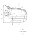
- FIG. 14 is a side view of the third embodiment as viewed from the X (+) side.
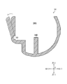
- FIG. 15 is a cross-sectional view taken along the line 15-15 of FIG.
- the cap 34 includes a cantilever piece 90 formed by the notch 91.
- the cantilever piece 90 includes a fixed end 90A, a free end 90B, and a stoppered portion 90C provided on the free end 90B.
- the tip body 32 includes a stopper 80. When the cap 34 is attached to the tip body 32, the stopper 80 and the stopper 90C engage with each other.
- Two notches 92 are formed in the cap 34.
- One notch 92 extends in the Z (+) direction from the side of the notch 91, and the other notch 92 extends in the Z ( ⁇ ) direction from the side of the opening window 34A.
- the notch 92 penetrates the outside and the inside of the cap 34.
- the cap 34 is not connected between the Y (+) side and the Y ( ⁇ ) side with the notch 92 as a boundary.
- one notch 92 has a shape (referred to as a triangular shape here) that tapers toward Z (+) at a portion continuous with the notch 91.
- the other one notch 92 has a taper (referred to here as an inverted triangle) in the direction of Z ( ⁇ ).
- the two notches 92 are in a positional relationship orthogonal to the cantilever piece 90.
- orthogonality includes perfect orthogonality and substantially orthogonality.
- the orthogonality includes the case where the angle formed by the cantilever piece 90 and the notch 92 (the smaller angle formed) is 80 ° or more.
- the shape of the notch 92 is not limited to the shape shown in FIG.
- the cap 34 is not separated between the apex of the triangular notch 92 and the apex of the inverted triangular notch 92. Additional notches may be formed between the vertices.
- the additional notch may be a continuous notch or a perforated notch.
- the notch 92 facilitates breaking the cap 34.
- two notches 92 are shown, but one may be used. If there is a notch 92 extending in the Z ( ⁇ ) direction from the side of the opening window 34A, the cap 34 can be broken.
- the cap 34 has a thin portion 93 parallel to the cantilever piece 90.
- the thin portion 93 extends in the Y (+) direction from a position near the fixed end 90A of the cantilever piece 90.
- the thin-walled portion 93 does not reach the tip portion of the cap 34.
- the thin-walled portion 93 has a groove portion formed inside the cap 34, and has a shape thinner than the other portions.
- Parallel includes perfectly parallel and substantially parallel.
- the cap 34 is provided with a linear notch 94 extending in the Y (+) direction from the thin wall portion 93.
- the notch 94 penetrates the outside and the inside of the cap 34.
- the cap 34 is not connected to the Z (+) side and the Z ( ⁇ ) side with the notch 94 as a boundary.
- the cap 34 is in the arrow direction (X (+) direction).
- the cap 34 can be destroyed with the thin portion 93 as a fulcrum by applying the force of.
- the stopper 80 and the stopper 90C are released, and the cap 34 is removed from the tip body 32.
- the linear notch 94 By providing the linear notch 94, the cap 34 can be easily broken. It is not necessary to provide the linear notch 94.
- the destruction of the cap 34 may be a deformation of the cap 34, and it is not necessary to separate the cap 34 into a plurality of pieces.
- the non-separable cap 34 is treated as a component for easy disposal.
- the present invention can be applied to an endoscope having a stand on the tip body, an endoscope in which a stand wire is connected to a lever on the tip body, and the like.
Landscapes
- Health & Medical Sciences (AREA)
- Life Sciences & Earth Sciences (AREA)
- Surgery (AREA)
- Biomedical Technology (AREA)
- Medical Informatics (AREA)
- Optics & Photonics (AREA)
- Pathology (AREA)
- Radiology & Medical Imaging (AREA)
- Biophysics (AREA)
- Engineering & Computer Science (AREA)
- Physics & Mathematics (AREA)
- Heart & Thoracic Surgery (AREA)
- Nuclear Medicine, Radiotherapy & Molecular Imaging (AREA)
- Molecular Biology (AREA)
- Animal Behavior & Ethology (AREA)
- General Health & Medical Sciences (AREA)
- Public Health (AREA)
- Veterinary Medicine (AREA)
- Gastroenterology & Hepatology (AREA)
- Endoscopes (AREA)
- Instruments For Viewing The Inside Of Hollow Bodies (AREA)
Priority Applications (3)
| Application Number | Priority Date | Filing Date | Title |
|---|---|---|---|
| JP2021540765A JP7270745B2 (ja) | 2019-08-22 | 2020-08-14 | 内視鏡 |
| CN202080057798.7A CN114245720B (zh) | 2019-08-22 | 2020-08-14 | 内窥镜 |
| US17/675,133 US12251080B2 (en) | 2019-08-22 | 2022-02-18 | Endoscope with removable cap |
Applications Claiming Priority (2)
| Application Number | Priority Date | Filing Date | Title |
|---|---|---|---|
| JP2019151976 | 2019-08-22 | ||
| JP2019-151976 | 2019-08-22 |
Related Child Applications (1)
| Application Number | Title | Priority Date | Filing Date |
|---|---|---|---|
| US17/675,133 Continuation US12251080B2 (en) | 2019-08-22 | 2022-02-18 | Endoscope with removable cap |
Publications (1)
| Publication Number | Publication Date |
|---|---|
| WO2021033642A1 true WO2021033642A1 (ja) | 2021-02-25 |
Family
ID=74661113
Family Applications (1)
| Application Number | Title | Priority Date | Filing Date |
|---|---|---|---|
| PCT/JP2020/030874 Ceased WO2021033642A1 (ja) | 2019-08-22 | 2020-08-14 | 内視鏡 |
Country Status (4)
| Country | Link |
|---|---|
| US (1) | US12251080B2 (https=) |
| JP (1) | JP7270745B2 (https=) |
| CN (1) | CN114245720B (https=) |
| WO (1) | WO2021033642A1 (https=) |
Families Citing this family (2)
| Publication number | Priority date | Publication date | Assignee | Title |
|---|---|---|---|---|
| WO2021033641A1 (ja) | 2019-08-22 | 2021-02-25 | 富士フイルム株式会社 | 起立台の成形方法及び内視鏡 |
| JP7270745B2 (ja) * | 2019-08-22 | 2023-05-10 | 富士フイルム株式会社 | 内視鏡 |
Citations (4)
| Publication number | Priority date | Publication date | Assignee | Title |
|---|---|---|---|---|
| US5860913A (en) * | 1996-05-16 | 1999-01-19 | Olympus Optical Co., Ltd. | Endoscope whose distal cover can be freely detachably attached to main distal part thereof with high positioning precision |
| JP2016174819A (ja) * | 2015-03-20 | 2016-10-06 | 富士フイルム株式会社 | 内視鏡 |
| WO2018016484A1 (ja) * | 2016-07-19 | 2018-01-25 | Hoya株式会社 | 内視鏡用キャップ、内視鏡および内視鏡用キャップの製造方法 |
| JP2018517440A (ja) * | 2015-08-07 | 2018-07-05 | デジタル エンドスコピー ゲーエムベーハー | 内視鏡、内視鏡用キャップ及び内視鏡用キャップ形成方法 |
Family Cites Families (43)
| Publication number | Priority date | Publication date | Assignee | Title |
|---|---|---|---|---|
| US4689184A (en) | 1982-11-02 | 1987-08-25 | Polaroid Corporation | Method for forming an optical connector |
| JP3313185B2 (ja) | 1993-05-11 | 2002-08-12 | オリンパス光学工業株式会社 | 内視鏡 |
| US5569157A (en) * | 1993-05-07 | 1996-10-29 | Olympus Optical Co., Ltd. | Endoscope |
| JPH06315459A (ja) | 1993-05-07 | 1994-11-15 | Olympus Optical Co Ltd | 内視鏡 |
| JP3228618B2 (ja) | 1993-11-26 | 2001-11-12 | オリンパス光学工業株式会社 | 内視鏡 |
| JP3299369B2 (ja) | 1993-12-10 | 2002-07-08 | 株式会社町田製作所 | 湾曲装置 |
| JPH08252210A (ja) | 1995-03-15 | 1996-10-01 | Olympus Optical Co Ltd | 内視鏡 |
| JPH0975300A (ja) | 1995-09-14 | 1997-03-25 | Toshiba Corp | 内視鏡スコープ及びこの内視鏡スコープを用いた内視鏡装置 |
| JPH09103415A (ja) | 1995-10-11 | 1997-04-22 | Olympus Optical Co Ltd | 磁気共鳴観測装置 |
| JP3776527B2 (ja) | 1996-09-30 | 2006-05-17 | オリンパス株式会社 | 内視鏡 |
| JPH11299728A (ja) | 1998-04-24 | 1999-11-02 | Fuji Photo Optical Co Ltd | 内視鏡の処置具起立装置 |
| US5971733A (en) | 1998-05-13 | 1999-10-26 | Huang; Chyong-Yen | Flat plug molding device |
| JP2001167640A (ja) | 1999-12-09 | 2001-06-22 | Yazaki Corp | 被覆電線の端末接続部およびその防水処理装置 |
| JP2001249250A (ja) | 2000-03-02 | 2001-09-14 | Ykk Corp | 光ファイバ一体型フェルールの製造方法及び装置 |
| JP2002174749A (ja) | 2000-09-27 | 2002-06-21 | Kyoei Senzai Kk | 光ファイバ接続用コネクタの複合フェルール及びこのフェルールの製造方法並びにこのフェルールを用いた光ファイバ接続用コネクタ |
| US20080212908A1 (en) | 2005-05-18 | 2008-09-04 | Ntn Corporation | Fluid Dynamic Bearing Device |
| JP4970877B2 (ja) * | 2006-05-17 | 2012-07-11 | オリンパスメディカルシステムズ株式会社 | 内視鏡 |
| CN100584557C (zh) | 2007-01-03 | 2010-01-27 | 刘顺峰 | 陶瓷插芯毛坯的成型装置及成型方法 |
| RU2510234C2 (ru) | 2008-12-10 | 2014-03-27 | Амбу А/С | Эндоскоп, имеющий корпус камеры, и способ изготовления корпуса камеры |
| JP2010273727A (ja) | 2009-05-26 | 2010-12-09 | Hoya Corp | 内視鏡用キャップおよび内視鏡装置 |
| JP2012040258A (ja) | 2010-08-20 | 2012-03-01 | Olympus Corp | 内視鏡部品の製造方法 |
| JP2012051006A (ja) | 2010-09-01 | 2012-03-15 | Olympus Corp | 成形装置 |
| US8338236B1 (en) | 2011-06-15 | 2012-12-25 | Freescale Semiconductor, Inc. | Vented substrate for semiconductor device |
| JP5820192B2 (ja) | 2011-08-24 | 2015-11-24 | 矢崎総業株式会社 | コネクタ端子への電線の接続方法及び圧着成形型 |
| JP6154106B2 (ja) | 2012-06-13 | 2017-06-28 | 矢崎総業株式会社 | 電線端末接続部の樹脂モールド方法及び樹脂モールド用の金型 |
| JP5959770B2 (ja) * | 2014-08-07 | 2016-08-02 | オリンパス株式会社 | 内視鏡の先端構造 |
| CN106102542B (zh) | 2014-08-19 | 2018-04-27 | 奥林巴斯株式会社 | 传递机构、抬起装置和插入设备 |
| JP6263494B2 (ja) * | 2015-03-20 | 2018-01-17 | 富士フイルム株式会社 | 内視鏡 |
| WO2017002588A1 (ja) * | 2015-06-30 | 2017-01-05 | オリンパス株式会社 | 挿入機器及び挿入機器を備える内視鏡 |
| CN107847106B (zh) * | 2015-06-30 | 2020-04-17 | 奥林巴斯株式会社 | 插入设备和具有插入设备的内窥镜 |
| WO2017006705A1 (ja) * | 2015-07-06 | 2017-01-12 | オリンパス株式会社 | 内視鏡のカバー取り外し治具 |
| JP6099851B1 (ja) * | 2015-07-15 | 2017-03-22 | オリンパス株式会社 | 内視鏡の先端カバーおよび内視鏡 |
| WO2017018301A1 (ja) | 2015-07-30 | 2017-02-02 | オリンパス株式会社 | 内視鏡 |
| JP6266194B2 (ja) * | 2016-01-14 | 2018-01-24 | オリンパス株式会社 | 内視鏡用カバー、内視鏡及びカバーユニット |
| WO2017122693A1 (ja) * | 2016-01-14 | 2017-07-20 | オリンパス株式会社 | 内視鏡用カバー、内視鏡、カバーユニット及び内視鏡ユニット |
| WO2017122692A1 (ja) * | 2016-01-14 | 2017-07-20 | オリンパス株式会社 | 内視鏡用カバー、内視鏡、カバーユニット及び内視鏡ユニット |
| WO2017163675A1 (ja) * | 2016-03-23 | 2017-09-28 | オリンパス株式会社 | 内視鏡、内視鏡システム |
| JP6275365B1 (ja) * | 2016-09-16 | 2018-02-07 | オリンパス株式会社 | 内視鏡のカバー取り外し治具、内視鏡システム |
| JP6715156B2 (ja) | 2016-10-04 | 2020-07-01 | オリンパス株式会社 | 内視鏡用湾曲管および内視鏡用湾曲管の製造方法 |
| JP2018068834A (ja) | 2016-11-01 | 2018-05-10 | オリンパス株式会社 | 走査型内視鏡および走査型内視鏡の製造方法 |
| JP6438177B1 (ja) * | 2017-03-31 | 2018-12-12 | オリンパス株式会社 | 内視鏡の先端カバー |
| JP6848098B2 (ja) * | 2018-01-31 | 2021-03-24 | オリンパス株式会社 | 挿入装置、挿入装置の先端部材および蓋部材 |
| JP7270745B2 (ja) * | 2019-08-22 | 2023-05-10 | 富士フイルム株式会社 | 内視鏡 |
-
2020
- 2020-08-14 JP JP2021540765A patent/JP7270745B2/ja active Active
- 2020-08-14 WO PCT/JP2020/030874 patent/WO2021033642A1/ja not_active Ceased
- 2020-08-14 CN CN202080057798.7A patent/CN114245720B/zh active Active
-
2022
- 2022-02-18 US US17/675,133 patent/US12251080B2/en active Active
Patent Citations (4)
| Publication number | Priority date | Publication date | Assignee | Title |
|---|---|---|---|---|
| US5860913A (en) * | 1996-05-16 | 1999-01-19 | Olympus Optical Co., Ltd. | Endoscope whose distal cover can be freely detachably attached to main distal part thereof with high positioning precision |
| JP2016174819A (ja) * | 2015-03-20 | 2016-10-06 | 富士フイルム株式会社 | 内視鏡 |
| JP2018517440A (ja) * | 2015-08-07 | 2018-07-05 | デジタル エンドスコピー ゲーエムベーハー | 内視鏡、内視鏡用キャップ及び内視鏡用キャップ形成方法 |
| WO2018016484A1 (ja) * | 2016-07-19 | 2018-01-25 | Hoya株式会社 | 内視鏡用キャップ、内視鏡および内視鏡用キャップの製造方法 |
Also Published As
| Publication number | Publication date |
|---|---|
| CN114245720B (zh) | 2025-05-30 |
| CN114245720A (zh) | 2022-03-25 |
| US12251080B2 (en) | 2025-03-18 |
| JPWO2021033642A1 (https=) | 2021-02-25 |
| JP7270745B2 (ja) | 2023-05-10 |
| US20220167835A1 (en) | 2022-06-02 |
Similar Documents
| Publication | Publication Date | Title |
|---|---|---|
| US11925316B2 (en) | Endoscope | |
| US11389054B2 (en) | Endoscope, wire attaching method for endoscope, and wire detaching method for endoscope | |
| US20140012087A1 (en) | Endoscope | |
| EP3689222A1 (en) | Endoscope | |
| US20230122213A1 (en) | Endoscope and treatment tool elevating mechanism | |
| WO2021033642A1 (ja) | 内視鏡 | |
| JP7317774B2 (ja) | 先端キャップ取外し治具 | |
| JPWO2019093240A1 (ja) | 内視鏡のフードの取り外し治具、及びフードとフードの取り外し治具のセット | |
| JP2025188239A (ja) | 起立台の成形方法及び内視鏡 | |
| JP7463233B2 (ja) | 内視鏡、及び装着部品 | |
| US12185914B2 (en) | Distal end cap detachment jig and endoscope | |
| JP7141963B2 (ja) | 内視鏡 | |
| JP7282240B2 (ja) | 内視鏡 | |
| JP2021049269A (ja) | 内視鏡 | |
| JP7074700B2 (ja) | 内視鏡 | |
| JPH0663008U (ja) | 内視鏡用チャンネル付き保護カバー部材 | |
| JPH06254035A (ja) | チャンネル付内視鏡カバー方式の内視鏡システム | |
| CN111629650A (zh) | 插入器具用清洗工具 | |
| EP3311728A1 (en) | Insertion apparatus and insertion device |
Legal Events
| Date | Code | Title | Description |
|---|---|---|---|
| 121 | Ep: the epo has been informed by wipo that ep was designated in this application |
Ref document number: 20854713 Country of ref document: EP Kind code of ref document: A1 |
|
| ENP | Entry into the national phase |
Ref document number: 2021540765 Country of ref document: JP Kind code of ref document: A |
|
| NENP | Non-entry into the national phase |
Ref country code: DE |
|
| 122 | Ep: pct application non-entry in european phase |
Ref document number: 20854713 Country of ref document: EP Kind code of ref document: A1 |
|
| WWG | Wipo information: grant in national office |
Ref document number: 202080057798.7 Country of ref document: CN |