WO2021014574A1 - 多重電力変換システム - Google Patents
多重電力変換システム Download PDFInfo
- Publication number
- WO2021014574A1 WO2021014574A1 PCT/JP2019/028871 JP2019028871W WO2021014574A1 WO 2021014574 A1 WO2021014574 A1 WO 2021014574A1 JP 2019028871 W JP2019028871 W JP 2019028871W WO 2021014574 A1 WO2021014574 A1 WO 2021014574A1
- Authority
- WO
- WIPO (PCT)
- Prior art keywords
- unit power
- current
- conversion system
- power converter
- power conversion
- Prior art date
- Legal status (The legal status is an assumption and is not a legal conclusion. Google has not performed a legal analysis and makes no representation as to the accuracy of the status listed.)
- Ceased
Links
Images






Classifications
-
- H—ELECTRICITY
- H02—GENERATION; CONVERSION OR DISTRIBUTION OF ELECTRIC POWER
- H02M—APPARATUS FOR CONVERSION BETWEEN AC AND AC, BETWEEN AC AND DC, OR BETWEEN DC AND DC, AND FOR USE WITH MAINS OR SIMILAR POWER SUPPLY SYSTEMS; CONVERSION OF DC OR AC INPUT POWER INTO SURGE OUTPUT POWER; CONTROL OR REGULATION THEREOF
- H02M7/00—Conversion of AC power input into DC power output; Conversion of DC power input into AC power output
- H02M7/42—Conversion of DC power input into AC power output without possibility of reversal
- H02M7/44—Conversion of DC power input into AC power output without possibility of reversal by static converters
- H02M7/48—Conversion of DC power input into AC power output without possibility of reversal by static converters using discharge tubes with control electrode or semiconductor devices with control electrode
- H02M7/493—Conversion of DC power input into AC power output without possibility of reversal by static converters using discharge tubes with control electrode or semiconductor devices with control electrode the static converters being arranged for operation in parallel
-
- H—ELECTRICITY
- H02—GENERATION; CONVERSION OR DISTRIBUTION OF ELECTRIC POWER
- H02M—APPARATUS FOR CONVERSION BETWEEN AC AND AC, BETWEEN AC AND DC, OR BETWEEN DC AND DC, AND FOR USE WITH MAINS OR SIMILAR POWER SUPPLY SYSTEMS; CONVERSION OF DC OR AC INPUT POWER INTO SURGE OUTPUT POWER; CONTROL OR REGULATION THEREOF
- H02M1/00—Details of apparatus for conversion
- H02M1/32—Means for protecting converters other than automatic disconnection
-
- H—ELECTRICITY
- H02—GENERATION; CONVERSION OR DISTRIBUTION OF ELECTRIC POWER
- H02M—APPARATUS FOR CONVERSION BETWEEN AC AND AC, BETWEEN AC AND DC, OR BETWEEN DC AND DC, AND FOR USE WITH MAINS OR SIMILAR POWER SUPPLY SYSTEMS; CONVERSION OF DC OR AC INPUT POWER INTO SURGE OUTPUT POWER; CONTROL OR REGULATION THEREOF
- H02M1/00—Details of apparatus for conversion
- H02M1/32—Means for protecting converters other than automatic disconnection
- H02M1/327—Means for protecting converters other than automatic disconnection against abnormal temperatures
-
- H—ELECTRICITY
- H02—GENERATION; CONVERSION OR DISTRIBUTION OF ELECTRIC POWER
- H02M—APPARATUS FOR CONVERSION BETWEEN AC AND AC, BETWEEN AC AND DC, OR BETWEEN DC AND DC, AND FOR USE WITH MAINS OR SIMILAR POWER SUPPLY SYSTEMS; CONVERSION OF DC OR AC INPUT POWER INTO SURGE OUTPUT POWER; CONTROL OR REGULATION THEREOF
- H02M7/00—Conversion of AC power input into DC power output; Conversion of DC power input into AC power output
- H02M7/42—Conversion of DC power input into AC power output without possibility of reversal
- H02M7/44—Conversion of DC power input into AC power output without possibility of reversal by static converters
- H02M7/48—Conversion of DC power input into AC power output without possibility of reversal by static converters using discharge tubes with control electrode or semiconductor devices with control electrode
- H02M7/483—Converters with outputs that each can have more than two voltages levels
-
- H—ELECTRICITY
- H02—GENERATION; CONVERSION OR DISTRIBUTION OF ELECTRIC POWER
- H02M—APPARATUS FOR CONVERSION BETWEEN AC AND AC, BETWEEN AC AND DC, OR BETWEEN DC AND DC, AND FOR USE WITH MAINS OR SIMILAR POWER SUPPLY SYSTEMS; CONVERSION OF DC OR AC INPUT POWER INTO SURGE OUTPUT POWER; CONTROL OR REGULATION THEREOF
- H02M7/00—Conversion of AC power input into DC power output; Conversion of DC power input into AC power output
- H02M7/42—Conversion of DC power input into AC power output without possibility of reversal
- H02M7/44—Conversion of DC power input into AC power output without possibility of reversal by static converters
- H02M7/48—Conversion of DC power input into AC power output without possibility of reversal by static converters using discharge tubes with control electrode or semiconductor devices with control electrode
- H02M7/483—Converters with outputs that each can have more than two voltages levels
- H02M7/487—Neutral point clamped inverters
-
- H—ELECTRICITY
- H02—GENERATION; CONVERSION OR DISTRIBUTION OF ELECTRIC POWER
- H02M—APPARATUS FOR CONVERSION BETWEEN AC AND AC, BETWEEN AC AND DC, OR BETWEEN DC AND DC, AND FOR USE WITH MAINS OR SIMILAR POWER SUPPLY SYSTEMS; CONVERSION OF DC OR AC INPUT POWER INTO SURGE OUTPUT POWER; CONTROL OR REGULATION THEREOF
- H02M7/00—Conversion of AC power input into DC power output; Conversion of DC power input into AC power output
- H02M7/42—Conversion of DC power input into AC power output without possibility of reversal
- H02M7/44—Conversion of DC power input into AC power output without possibility of reversal by static converters
- H02M7/48—Conversion of DC power input into AC power output without possibility of reversal by static converters using discharge tubes with control electrode or semiconductor devices with control electrode
- H02M7/53—Conversion of DC power input into AC power output without possibility of reversal by static converters using discharge tubes with control electrode or semiconductor devices with control electrode using devices of a triode or transistor type requiring continuous application of a control signal
- H02M7/537—Conversion of DC power input into AC power output without possibility of reversal by static converters using discharge tubes with control electrode or semiconductor devices with control electrode using devices of a triode or transistor type requiring continuous application of a control signal using semiconductor devices only, e.g. single switched pulse inverters
-
- H—ELECTRICITY
- H02—GENERATION; CONVERSION OR DISTRIBUTION OF ELECTRIC POWER
- H02M—APPARATUS FOR CONVERSION BETWEEN AC AND AC, BETWEEN AC AND DC, OR BETWEEN DC AND DC, AND FOR USE WITH MAINS OR SIMILAR POWER SUPPLY SYSTEMS; CONVERSION OF DC OR AC INPUT POWER INTO SURGE OUTPUT POWER; CONTROL OR REGULATION THEREOF
- H02M7/00—Conversion of AC power input into DC power output; Conversion of DC power input into AC power output
- H02M7/42—Conversion of DC power input into AC power output without possibility of reversal
- H02M7/44—Conversion of DC power input into AC power output without possibility of reversal by static converters
- H02M7/48—Conversion of DC power input into AC power output without possibility of reversal by static converters using discharge tubes with control electrode or semiconductor devices with control electrode
- H02M7/53—Conversion of DC power input into AC power output without possibility of reversal by static converters using discharge tubes with control electrode or semiconductor devices with control electrode using devices of a triode or transistor type requiring continuous application of a control signal
- H02M7/537—Conversion of DC power input into AC power output without possibility of reversal by static converters using discharge tubes with control electrode or semiconductor devices with control electrode using devices of a triode or transistor type requiring continuous application of a control signal using semiconductor devices only, e.g. single switched pulse inverters
- H02M7/5387—Conversion of DC power input into AC power output without possibility of reversal by static converters using discharge tubes with control electrode or semiconductor devices with control electrode using devices of a triode or transistor type requiring continuous application of a control signal using semiconductor devices only, e.g. single switched pulse inverters in a bridge configuration
- H02M7/53871—Conversion of DC power input into AC power output without possibility of reversal by static converters using discharge tubes with control electrode or semiconductor devices with control electrode using devices of a triode or transistor type requiring continuous application of a control signal using semiconductor devices only, e.g. single switched pulse inverters in a bridge configuration with automatic control of output voltage or current
-
- H—ELECTRICITY
- H02—GENERATION; CONVERSION OR DISTRIBUTION OF ELECTRIC POWER
- H02M—APPARATUS FOR CONVERSION BETWEEN AC AND AC, BETWEEN AC AND DC, OR BETWEEN DC AND DC, AND FOR USE WITH MAINS OR SIMILAR POWER SUPPLY SYSTEMS; CONVERSION OF DC OR AC INPUT POWER INTO SURGE OUTPUT POWER; CONTROL OR REGULATION THEREOF
- H02M1/00—Details of apparatus for conversion
- H02M1/0003—Details of control, feedback or regulation circuits
- H02M1/0009—Devices or circuits for detecting current in a converter
Definitions
- the present invention relates to a multiple power conversion system.
- Patent Document 1 discloses a multiple power conversion system including a plurality of three-level power converters. According to the multiple power conversion system, it is possible to prevent the temperature rise of the DC smoothing capacitor and to stabilize the potential of the DC bus.
- a circulating current may flow between a plurality of power converters.
- a current sensor in each phase on the AC side of a plurality of power converters. In this case, the number of current sensors increases.
- An object of the present invention is to provide a multiplex power conversion system capable of detecting a circulating current with a small number of current sensors.
- the multiplex power conversion system includes n first to nth plurality of unit power converters, in which the positive DC sides of each other are connected and the negative DC sides of each other are connected, and n is 2 or more.
- a plurality of unit power converters in which the DC positive sides of each other are connected, the DC negative sides of each other are connected, and the DC neutral points of each other are connected, and the plurality of unit powers are connected. It was equipped with a plurality of current sensors for detecting the current flowing through each of the DC neutral points of the converter.
- the circulating current is detected based on the detection result of the current sensor provided on the DC side. Therefore, the circulating current can be detected with a small number of current sensors.
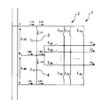
- FIG. It is a block diagram of the multiplex power conversion system in Embodiment 1.
- FIG. It is a block diagram of the 1st example of the unit power converter of the multiplex power conversion system in Embodiment 1.
- FIG. It is a block diagram of the 2nd example of the unit power converter of the multiplex power conversion system in Embodiment 1.
- FIG. It is a block diagram for demonstrating the method of suppressing the circulating current of the multiplex power conversion system in Embodiment 1.
- FIG. It is a block diagram for demonstrating the protection method of the unit power converter 1 of the multiplex power conversion system in Embodiment 1.
- FIG. It is a block diagram of the main part of the unit power converter of the multiplex power conversion system in Embodiment 1.
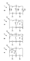
- FIG. 1 It is a figure which shows the mode of the short circuit failure of the unit power converter of the multiple power conversion system in Embodiment 1.
- FIG. It is a figure which shows the theoretical value of the non-uniform amount at the time of the short circuit occurrence in the multiple power conversion system in Embodiment 1.
- FIG. It is a figure which shows the theoretical value of the non-uniform amount at the time of the short circuit occurrence in the multiple power conversion system in Embodiment 1.
- FIG. It is a flowchart for demonstrating the outline of the operation of the control device of the multiplex power conversion system in Embodiment 1.
- FIG. It is a hardware block diagram of the control device of the multiplex power conversion system in Embodiment 1.
- FIG. 2 It is a block diagram of the multiplex power conversion system in Embodiment 2. It is a block diagram of the main part of the unit power converter of the multiple power conversion system in Embodiment 2.
- FIG. It is a figure which shows the theoretical value of the non-uniform amount at the time of the short circuit occurrence in the multiple power conversion system in Embodiment 2. It is a figure which shows the theoretical value of the non-uniform amount at the time of the short circuit occurrence in the multiple power conversion system in Embodiment 2.
- Embodiment 4 It is a block diagram of the multiplex power conversion system in Embodiment 4. It is a block diagram of the 1st example of the unit power converter of the multiplex power conversion system in Embodiment 4. It is a block diagram of the 2nd example of the unit power converter of the multiplex power conversion system in Embodiment 4. It is a block diagram of the multiplex power conversion system in Embodiment 5. It is a block diagram of the multiplex power conversion system in Embodiment 6. It is a block diagram of the multiplex power conversion system in Embodiment 7. It is a block diagram of the multiplex power conversion system in Embodiment 8. It is a block diagram of the multiplex power conversion system in Embodiment 9.
- FIG. 1 is a configuration diagram of a multiplex power conversion system according to the first embodiment.
- the multiplex power conversion system includes a plurality of unit power converters 1.
- the DC side is connected to a DC power source (not shown).
- the AC side is connected to the AC load.
- Each of the plurality of unit power converters 1 includes a switching element group 2, a positive DC capacitor 3, a negative DC capacitor 4, and a plurality of reactors 5.
- the switching element group 2 includes a plurality of switching elements (not shown).
- the positive DC capacitor 3 is connected between the DC positive side P of the unit power converter 1 and the DC neutral point M.
- the negative DC capacitor 4 is connected between the DC negative side N of the unit power converter 1 and the DC neutral point M.
- FIG. 1 only one of the plurality of reactors 5 is illustrated. Each of the plurality of reactors 5 is connected in series to each phase on the AC side.
- the DC positive sides P of each other are connected to each other.
- the negative DC sides N of each other are connected to each other.
- the DC neutral points M of each other are not connected to each other.
- a plurality of DC side current sensors 6 are provided on each of the DC positive side Ps of the plurality of unit power converters 1.
- the plurality of DC side current sensors 6 are provided so as to be able to detect the current flowing through each of the DC positive side Ps of the plurality of unit power converters 1.
- a plurality of DC side current sensors 6 may be provided on each of the DC negative sides N of the plurality of unit power converters 1.
- the plurality of DC side current sensors 6 are provided so as to be able to detect the current flowing through each of the DC negative sides N of the plurality of unit power converters 1.
- control device 7 transmits the same gate signal to each of the plurality of unit power converters 1.
- control device 7 transmits a gate signal generated from the same voltage command value and different carrier waves to each of the plurality of unit power converters 1.
- the control device 7 calculates the non-uniform amount of the current flowing through each of the plurality of unit power converters 1 based on the detection results of the plurality of DC side current sensors 6.
- the control device 7 detects a non-uniform amount of current in each of the n unit power converters 1 constituting the multiple power conversion system. Specifically, for example, the control device 7 flows through each unit power converter 1 using the following equation (1), where the current flowing through the i- th unit power converter 1 out of n units is ii. Calculate the non-uniform amount of current.
- the control device 7 controls the operation of the switching element group 22 of the plurality of unit power converters 1 based on the calculation result of the non-uniform amount of the current.
- FIG. 2 is a configuration diagram of a first example of a unit power converter of the multiple power conversion system according to the first embodiment.
- FIG. 2 is an example of a configuration of a three-phase, three-level unit power converter 1 using a self-excited semiconductor element and a diode.
- a positive DC capacitor 3 and a negative DC capacitor 4 are connected in series between the DC terminals, and a DC neutral point exists at the intermediate point thereof.
- any one of the DC positive side P, the DC neutral point M, and the DC negative side N is given according to those signals.
- the potential of is output to the AC terminal of each phase.
- FIG. 3 is a configuration diagram of a second example of the unit power converter of the multiple power conversion system according to the first embodiment.
- FIG. 3 is a configuration example of a three-phase, three-level unit power converter 1 using a self-excited semiconductor element and a diode.
- the unit power converter 1 as in the unit power converter 1 of FIG. 2, by giving an on / off signal to each gate of the self-excited semiconductor element inside the unit power converter 1, those signals are also generated.
- the potential of any of the DC positive side P, the DC neutral point M, and the DC negative side N is output to each phase AC terminal according to the above.
- the configuration of the unit power converter 1 is not limited to these two configurations.
- the number of phases is not limited to three phases and may be any number of phases.
- an example of a 3-level unit power converter 1 is shown here as an example, the number of levels is not limited to 3, and any level of unit power converter 1 having 3 or more levels may be used.
- FIG. 4 is a block diagram for explaining a method of suppressing the circulating current of the multiple power conversion system according to the first embodiment.
- G (s) is a low-pass filter and feedback gain.
- a zero-phase voltage (non-uniform amount ⁇ v i0 ) is output to the AC side of the unit power converter 1 in a direction of suppressing the zero-phase circulating current (non-uniform amount ⁇ i i0 ).
- the control device 7 calculates the target value ⁇ v i0 * of the non-uniform amount of the zero-phase voltage for the plurality of unit power converters 1.
- the controller 7 controls the uneven amount .DELTA.i i0 current by operating the voltage v i0 by detecting the uneven amount .DELTA.i IPj current.
- FIG. 5 is a block diagram for explaining a protection method of the unit power converter 1 of the multiple power conversion system according to the first embodiment.
- the control device 7 calculates a non-uniform amount ⁇ i iPj of the current flowing through each unit power converter 1 and determines whether or not the calculated value is larger than a preset threshold value.
- the control device 7 performs a protective operation. Specifically, the control device 7 transmits a gate block signal GB that turns off the plurality of switching element groups 2.
- FIG. 6 is a configuration diagram of a main part of a unit power converter of the multiple power conversion system according to the first embodiment.
- FIG. 7 is a diagram showing a mode of short-circuit failure of the unit power converter of the multiple power conversion system according to the first embodiment.
- the control device 7 detects a short-circuit failure based on the detected value of the DC side current sensor 6.
- FIG. 7 shows a path through which a current flows when a short-circuit failure occurs, and may be mode A to mode D depending on the location of the short-circuit failure.
- FIGS. 8 and 9 are diagrams showing theoretical values of a non-uniform amount when a short circuit occurs in the multiple power conversion system according to the first embodiment.
- the physical quantity with the subscript i is the physical quantity in the unit power converter in which the short-circuit failure has occurred
- the physical quantity with the subscript j is the physical quantity in the unit power converter other than the unit power converter in which the short-circuit failure has occurred.
- the current non-uniform amount on the DC P side is ⁇ i iP1 and the current non-uniform amount on the DC N side is ⁇ i iN1 .
- the current non-uniform amount on the DC P side is ⁇ i jP1 and the current non-uniform amount on the DC N side is ⁇ i jN1 .
- the theoretical value of the non-uniform amount in the unit power converter i in which the short-circuit failure occurs is as shown in the new equation (1) or the new equation (2).
- the new equation (1) is the non-uniform amount of the detected value when the DC side current sensor 6 is provided on the DC positive side P
- the new equation (2) is provided with the DC side current sensor 6 on the DC negative side N. It is a non-uniform amount of the detected value in the case of.
- the theoretical value of the non-uniform amount in the unit power converter i in which the short-circuit failure occurs is as shown in the new equation (3) or the new equation (4).
- the new equation (3) is the non-uniform amount of the detected value when the DC side current sensor 6 is provided on the DC positive side P
- the new equation (4) is provided with the DC side current sensor 6 on the DC negative side N. It is a non-uniform amount of the detected value in the case of.
- the theoretical value of the non-uniform amount in the unit power converter i in which the short-circuit failure occurs is as shown in the new equation (5) or the new equation (6).
- the new equation (5) is the non-uniform amount of the detected value when the DC side current sensor 6 is provided on the DC positive side P
- the new equation (6) is provided with the DC side current sensor 6 on the DC negative side N. It is a non-uniform amount of the detected value in the case of.
- the theoretical value of the non-uniform amount in the unit power converter i in which the short-circuit failure occurs is as shown in the new equation (7) or the new equation (8).
- the new equation (7) is the non-uniform amount of the detected value when the DC side current sensor 6 is provided on the DC positive side P
- the new equation (8) is provided with the DC side current sensor 6 on the DC negative side N. It is a non-uniform amount of the detected value in the case of.
- a short-circuit failure of the unit power converter can be detected by setting a value smaller than the non-uniform amount of the new equations (1) to (8) as a threshold value to be compared with the non-uniform amount.
- the value of the unit power converter (subscript i) in which the short-circuit failure occurs is higher than the value of the other unit power converters (subscript j).
- the size becomes large it is possible to compare the non-uniform amount of each unit power converter detected by the control device and identify the one with the largest size as the unit power converter in which the failure occurred. You can. This is because (1-1 / n)> 1 / n.
- FIG. 10 is a flowchart for explaining an outline of the operation of the control device of the multiple power conversion system according to the first embodiment.
- step S1 the control device 7 calculates the non-uniform amount of the current flowing through each unit power converter 1 and determines whether or not the calculated value is larger than a preset threshold value.
- step S1 If the non-uniform amount of the current flowing through each unit power converter 1 in step S1 is not larger than the preset threshold value, the control device 7 performs the operation of step S2.
- step S2 the control device 7 transmits a gate signal to the plurality of switching element groups 22 based on the voltage command value. After that, the control device 7 performs the operation of step S1.
- step S1 When the non-uniform amount of the current flowing through each unit power converter 1 in step S1 is larger than the preset threshold value, the control device 7 performs the operation of step S3. In step S3, the control device 7 transmits a gate signal that turns off the plurality of switching element groups 2. After that, the control device 7 ends the operation.
- the circulating current is detected based on the detection result of the DC side current sensor 6. Therefore, the circulating current can be detected with a small number of current sensors.
- the circulating current may be detected based on the detection result of the DC side current sensor 6, which is one less than the number of unit power converters 1. In this case, the circulating current can be detected with a smaller current sensor.
- the plurality of unit power converters 1 are controlled based on the detection result of the DC side current sensor 6. Therefore, the circulating current can be suppressed with a small amount of current sensor.
- control device 7 can transmit the gate signals of the plurality of unit power converters 1 based on the detection results of the plurality of DC side current sensors 6 to suppress the zero-phase component of the circulating current. It is possible to take a small margin of the rated current of the parts (mainly AC reactors) rated for superimposition, and it is possible to suppress extra costs.
- control device 7 turns off at least one switching element of the plurality of unit power converters 1 based on the detection results of the plurality of DC side current sensors 6. Therefore, when a short-circuit failure of the positive DC capacitor 3 or the negative DC capacitor 4, an abnormal decrease in capacity, or an abnormal increase in leakage current is detected, the positive DC capacitor 3 or the negative DC capacitor 4 is overheated, bursts, or liquid. Leakage can be prevented.
- the failure detection principle when a short-circuit failure of a switching element occurs has been explained, but it is not limited to the short-circuit failure of the switching element, but the short-circuit failure of the positive side DC capacitor or the negative side DC capacitor, capacity reduction, leakage current increase, and AC inductance It is also possible to detect the occurrence of abnormalities such as an abnormal decrease in inductance due to a short-circuit failure between layers. This is because even if these abnormalities occur, the non-uniform amount of the detection value of the DC side current sensor 6 will have a certain magnitude, so if the detection threshold value is set lower than that magnitude, This is because it can be determined to be abnormal.
- the abnormality determination may be performed by the same method as that described in Japanese Patent Application Laid-Open No. 2017-22816.
- a switch may be provided on at least one of the DC positive side and the DC negative side. At this time, the switch may be disconnected from the failed unit power converter 1 based on the detected values of the plurality of current sensors, and the unit power converter 1 may be used alone for operation.
- FIG. 11 is a hardware configuration diagram of the control device of the multiplex power conversion system according to the first embodiment.
- Each function of the control device 7 can be realized by a processing circuit.
- the processing circuit includes at least one processor 8a and at least one memory 8b.
- the processing circuit comprises at least one dedicated hardware 9.
- each function of the control device 7 is realized by software, firmware, or a combination of software and firmware. At least one of the software and firmware is written as a program. At least one of the software and firmware is stored in at least one memory 8b. At least one processor 8a realizes each function of the control device 7 by reading and executing a program stored in at least one memory 8b. At least one processor 8a is also referred to as a central processing unit, a processing unit, an arithmetic unit, a microprocessor, a microcomputer, and a DSP.
- at least one memory 8b is a non-volatile or volatile semiconductor memory such as RAM, ROM, flash memory, EPROM, EEPROM, magnetic disk, flexible disk, optical disk, compact disk, mini disk, DVD or the like.
- the processing circuit comprises at least one dedicated hardware 9
- the processing circuit may be implemented, for example, as a single circuit, a composite circuit, a programmed processor, a parallel programmed processor, an ASIC, an FPGA, or a combination thereof.
- each function of the control device 7 is realized by a processing circuit.
- each function of the control device 7 is collectively realized by a processing circuit.
- a part may be realized by the dedicated hardware 9, and the other part may be realized by software or firmware.
- the function of transmitting a gate signal is realized by a processing circuit as dedicated hardware 9, and the function other than the function of transmitting a gate signal is a program in which at least one processor 8a is stored in at least one memory 8b. It may be realized by reading and executing.
- the processing circuit realizes each function of the control device 7 by hardware 9, software, firmware, or a combination thereof.
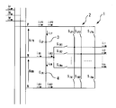
- FIG. 12 is a configuration diagram of the multiplex power conversion system according to the second embodiment.
- the same or corresponding parts as those of the first embodiment are designated by the same reference numerals. The explanation of the relevant part is omitted.
- the DC neutral points M of each other are not connected to each other.
- the DC neutral points M are connected to each other.
- a plurality of DC side current sensors 6 are provided at each of the DC neutral points M of the plurality of unit power converters 1.
- the plurality of DC side current sensors 6 are provided so as to be able to detect the current flowing through each of the DC neutral points M of the plurality of unit power converters 1.
- a plurality of DC side current sensors 6 may be provided at each of the DC neutral points M of the unit power converter 1 excluding one of the plurality of unit power converters 1.
- the plurality of DC side current sensors 6 are provided so as to be able to detect the current flowing through each of the DC neutral points M of the unit power converter 1 excluding one of the plurality of unit power converters 1. ..
- the DC side integrated current sensor 10 is provided on the DC positive side P.
- the DC side integrated current sensor 10 is provided so as to be able to detect the current flowing through the DC positive side P.
- the control device 7 calculates the non-uniform amount of the current flowing through each of the plurality of unit power converters 1 based on the detection results of the plurality of DC side current sensors 6.
- the control device 7 controls the operation of the switching element group 2 of the plurality of unit power converters 1 based on the calculation result of the non-uniform amount of the current.
- FIG. 13 is a configuration diagram of a main part of a unit power converter of the multiple power conversion system according to the second embodiment.
- control device 7 detects a short-circuit failure based on the detected values of the DC side current sensor 6 and the DC side integrated current sensor 10.
- 14 and 15 are diagrams showing theoretical values of a non-uniform amount when a short circuit occurs in the multiple power conversion system according to the second embodiment.
- the physical quantity with the subscript i is the physical quantity in the unit power converter in which the short-circuit failure has occurred
- the physical quantity with the subscript j is the physical quantity in the unit power converter other than the unit power converter in which the short-circuit failure has occurred.
- the current non-uniform amount on the DC P side is ⁇ i iP1
- the current non-uniform amount on the DC M side is ⁇ i iM1
- the current non-uniform amount on the DC N side is ⁇ i iN1 .
- the current non-uniform amount on the DC P side is ⁇ i jP1
- the current non-uniform amount on the DC M side is ⁇ i jM1
- the current non-uniform amount on the DC N side is ⁇ i jN1. Is.
- the value of the unit power converter (subscript i) in which the short circuit failure occurs is higher than the value of the other unit power converters (subscript j).
- the size becomes large it is possible to compare the non-uniform amount of each unit power converter detected by the control device and identify the one with the largest size as the unit power converter in which the failure occurred. You can. This is because (1-1 / n)> 1 / n.
- the circulating current is detected based on the detection results of the DC side current sensor 6 and the DC side integrated current sensor 10. Therefore, the circulating current can be detected with a small number of current sensors.
- the plurality of unit power converters 1 are controlled based on the detection results of the DC side current sensor 6 and the DC side integrated current sensor 10. Therefore, the circulating current can be suppressed with a small amount of current sensor.
- the DC side current sensor 6 detects the current flowing through the DC neutral point M.
- the current is smaller than the current flowing through the DC positive side P and the DC negative side N. Therefore, the rating of the DC side current sensor 6 can be reduced.
- the conductor may be thin. Therefore, it becomes easy to provide the DC side current sensor 6. As a result, the degree of freedom in mounting the DC side current sensor 6 can be increased.
- FIG. 16 is a configuration diagram of the multiplex power conversion system according to the third embodiment.
- the same or corresponding parts as those of the second embodiment are designated by the same reference numerals. The explanation of the relevant part is omitted.
- the plurality of DC side current sensors 6 are provided in the plurality of unit power converters 1, respectively.
- the plurality of DC side current sensors 6 are provided so as to be able to collectively detect the difference between the currents flowing through the DC positive side P and the DC negative side N of the plurality of unit power converters 1.
- FIG. 17 is a diagram showing a theoretical value of a non-uniform amount when a short circuit occurs in the multiple power conversion system according to the third embodiment.
- the physical quantity with the subscript i is the physical quantity in the unit power converter in which the short-circuit failure has occurred
- the physical quantity with the subscript j is the physical quantity in the unit power converter other than the unit power converter in which the short-circuit failure has occurred.
- the current non-uniform amount on the DC P side is ⁇ i iP1 and the current non-uniform amount on the DC N side is ⁇ i iN1 .
- the current non-uniform amount on the DC P side is ⁇ i jP1 and the current non-uniform amount on the DC N side is ⁇ i jN1 .
- the value of the unit power converter (subscript i) in which the short-circuit failure occurs is higher than the value of the other unit power converters (subscript j).
- the size becomes large it is possible to compare the non-uniform amount of each unit power converter detected by the control device and identify the one with the largest size as the unit power converter in which the failure occurred. You can. This is because (1-1 / n)> 1 / n.
- the plurality of DC side current sensors 6 collectively detect the difference between the currents flowing in the DC positive side P and the DC negative side N of the plurality of unit power converters 1. .. Therefore, the circulating current can be detected with a small number of current sensors.
- control device can detect all short-circuit failures from mode A to mode D based on the detection results of the plurality of DC side current sensors 6.
- FIG. 18 is a configuration diagram of the multiplex power conversion system according to the fourth embodiment.
- the same or corresponding parts as those of the second embodiment are designated by the same reference numerals. The explanation of the relevant part is omitted.
- the unit power converter 1 of the fourth embodiment is a two-level power converter.
- FIG. 19 is a configuration diagram of a first example of the unit power converter of the multiple power conversion system according to the fourth embodiment.
- FIG. 19 is an example of a configuration of a two-level unit power converter 1 that converts DC power into AC power.
- FIG. 20 is a configuration diagram of a second example of the unit power converter of the multiple power conversion system according to the fourth embodiment.
- FIG. 20 is a configuration example of a two-level unit power converter 1 that converts DC power into DC power.
- the DC side current sensor 6 is provided in the two-level unit power converter 1. Even in this case, the circulating current can be detected with a small number of current sensors.
- FIG. 21 is a configuration diagram of the multiplex power conversion system according to the fifth embodiment.
- the same or corresponding parts as those of the second embodiment are designated by the same reference numerals. The explanation of the relevant part is omitted.
- the plurality of reactors 11 are provided on the DC positive side P and the DC negative side N of the plurality of unit power converters 1, respectively.
- the plurality of reactors 11 are provided on the DC positive side P of the plurality of unit power converters 1.
- the circulating current can be detected with a small number of current sensors.
- the reactor 11 may be provided at the DC neutral point M.
- the circulating current can be detected with a small number of current sensors.
- FIG. 22 is a configuration diagram of the multiplex power conversion system according to the sixth embodiment.
- the same or corresponding parts as those of the second embodiment are designated by the same reference numerals. The explanation of the relevant part is omitted.
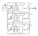
- each output side of the plurality of unit power converters 1 is connected to a single-phase multi-winding transformer.
- Each of the plurality of unit power converters 1 is a unit power converter 1 for one phase.
- the AC side current sensor 12 is provided on the output side of any one of the plurality of unit power converters 1.
- the result of the suppression of the input side of the non-uniform amount .DELTA.i UIM1 uneven amount .DELTA.i VIM1, is inhibited with non-uniform weight .DELTA.i Ui and uneven amount .DELTA.i Vi of the output side .. Therefore, the AC side current sensor 12 can be integrated into one.
- FIG. 23 is a configuration diagram of the multiplex power conversion system according to the seventh embodiment.
- the same or corresponding parts as those of the sixth embodiment are designated by the same reference numerals. The explanation of the relevant part is omitted.
- each output side of the plurality of unit power converters 1 is connected to a three-phase multi-winding transformer.
- the plurality of AC side current sensors 12 are provided on the output side of the unit power converter 1 corresponding to each of the two phases of the plurality of unit power converters 1.
- the plurality of AC side current sensors 12 are provided on the output side of the unit power converter 1 corresponding to each of the two phases of the plurality of unit power converters 1. .. Also in this case, the circulating current can be suppressed and the number of current sensors can be reduced.
- the AC side current sensor calculates the circulating current between U1-U2-U3, the circulating current between V1-V2-V3, and the circulating current between W1-W2-W3.
- Current sensors are provided in, for example, U1, U2, U3, V1, V2, and V3 for detection and suppression, or for failure detection.
- the W phase is unnecessary because it can be calculated by Kirchhoff's current law.
- current sensors 6 are installed between the neutral points of the unit power converter as in the present embodiment, the circulating current is suppressed by these sensors, or a failure is detected as in the second embodiment.
- the sensors on the AC side can be omitted in two places, for example, U1 and V1.
- the reason for leaving the U1 and V1 current sensors is to recognize the total value of the currents on the AC side. Under the condition that no circulating current is flowing, that is, there is no non-uniform amount in the current sensors 6 provided in each phase, the current values of U1, U2, and U3 are equal, and the current values of V1, V2, and V3 are equal. The current values of W1, W2, and W3 are equal.
- the current values of all U1, U2, U3, V1, V2, V3, W1, W2, and W3 can be estimated. Thereby, the total value of the current on the AC side can be estimated.
- FIG. 24 is a configuration diagram of the multiplex power conversion system according to the eighth embodiment.
- the same or corresponding parts as those of the sixth embodiment are designated by the same reference numerals. The explanation of the relevant part is omitted.
- the plurality of reactors 13 are provided on the output side of the plurality of unit power converters 1, respectively.
- the plurality of reactors 13 are provided on the output side of the plurality of unit power converters 1, respectively. Also in this case, the circulating current can be suppressed and the number of current sensors can be reduced.
- the AC side current sensor detects and suppresses the circulating current between U1-U2-U3, or for failure detection, for example, U1, U2, U3. Is provided with a current sensor.
- the V phase is unnecessary because it can be calculated by Kirchhoff's current law.
- current sensors 6 are installed between the neutral points of the unit power converter as in the present embodiment, the circulating current is suppressed by these sensors, or a failure is detected as in the second embodiment. Since it is not necessary to use all the current values of U1, U2, and U3, there is an effect that the sensor on the AC side can be omitted in one place of U1, for example.
- the reason for leaving the current sensor of U1 is to recognize the total value of the current on the AC side. Under the condition that no circulating current is flowing, that is, there is no non-uniform amount in the current sensors 6 provided in each phase, the current values of U1, U2, and U3 are equal, and the current values of V1, V2, and V3 are equal. .. By using this and Kirchhoff's current law, the current values of all U1, U2, U3, V1, V2, and V3 can be estimated. Thereby, the total value of the current on the AC side can be estimated.
- FIG. 25 is a configuration diagram of the multiplex power conversion system according to the ninth embodiment.
- the same or corresponding parts as those of the sixth embodiment are designated by the same reference numerals. The explanation of the relevant part is omitted.
- the plurality of unit power converters 1 are divided into groups corresponding to different phases.
- the DC neutral points M are connected to each other.
- the DC neutral points M are not connected to each other.
- a plurality of DC side current sensors 6 are provided on each of the DC positive side Ps of the plurality of unit power converters 1.
- the plurality of DC side current sensors 6 are provided so as to be able to detect the current flowing through each of the DC positive side Ps of the plurality of unit power converters 1.
- a plurality of DC side current sensors 6 may be provided on each of the DC negative sides N of the plurality of unit power converters 1.
- the plurality of DC side current sensors 6 are provided so as to be able to detect the current flowing through each of the DC negative sides N of the plurality of unit power converters 1.
- the DC neutral points M of each set are connected to each other in the unit power converter 1 of each set. In different sets of unit power converters 1, the DC neutral points M are not connected to each other.
- the current sensor on the AC side detects and suppresses the circulating current between U1-U2-U3 and the circulating current between V1-V2-V3, or detects a failure. Therefore, for example, current sensors are provided in U1, U2, and U3. The V phase is unnecessary because it can be calculated by Kirchhoff's current law.
- the current sensor 6 is installed on the DC side of the unit power converter as in the present embodiment, the circulating current is suppressed by these sensors, or the failure is detected as in the second embodiment, so that U1, U2, Since it is not necessary to use all the current values of U3, the sensor on the AC side can be omitted in one place of U1, for example.
- the reason for leaving the current sensor of U1 is to recognize the total value of the current on the AC side. Under the condition that no circulating current is flowing, that is, there is no non-uniform amount in the current sensors 6 provided in each phase, the current values of U1, U2, and U3 are equal, and the current values of V1, V2, and V3 are equal. .. By using this and Kirchhoff's current law, the current values of all U1, U2, U3, V1, V2, and V3 can be estimated. Thereby, the total value of the current on the AC side can be estimated.
- Failure detection can be performed faster by providing only U1 on the AC side and providing a current sensor on the DC side as in the embodiment, rather than providing current sensors on U1, U2, and U3 on the AC side. This is because the change in current when a failure occurs is steeper on the DC side than on the AC side.
- each of the plurality of unit power converters 1 may be provided with a plurality of switches provided at at least two of the DC positive side P, the DC negative side N, and the DC neutral point M.
- the plurality of switches may be disconnected in the failed unit power converter 1 based on the detected values of the plurality of DC side current sensors 6.
- the operation of the multiplex power conversion system can be maintained, leaving the unit power converter 1 that has not failed. This is valid for all of the first to ninth embodiments.
- the multiple power conversion system according to the present invention can be used in a system that detects a circulating current with a small number of current sensors.
Landscapes
- Engineering & Computer Science (AREA)
- Power Engineering (AREA)
- Inverter Devices (AREA)
Priority Applications (5)
| Application Number | Priority Date | Filing Date | Title |
|---|---|---|---|
| PCT/JP2019/028871 WO2021014574A1 (ja) | 2019-07-23 | 2019-07-23 | 多重電力変換システム |
| EP19938114.6A EP4007154A4 (en) | 2019-07-23 | 2019-07-23 | Multiplex power conversion system |
| US17/416,623 US12301132B2 (en) | 2019-07-23 | 2019-07-23 | Multiple power conversion system |
| CN201980085810.2A CN113228493B (zh) | 2019-07-23 | 2019-07-23 | 复合电力变换系统 |
| JP2021534459A JP7294424B2 (ja) | 2019-07-23 | 2019-07-23 | 多重電力変換システム |
Applications Claiming Priority (1)
| Application Number | Priority Date | Filing Date | Title |
|---|---|---|---|
| PCT/JP2019/028871 WO2021014574A1 (ja) | 2019-07-23 | 2019-07-23 | 多重電力変換システム |
Publications (1)
| Publication Number | Publication Date |
|---|---|
| WO2021014574A1 true WO2021014574A1 (ja) | 2021-01-28 |
Family
ID=74193545
Family Applications (1)
| Application Number | Title | Priority Date | Filing Date |
|---|---|---|---|
| PCT/JP2019/028871 Ceased WO2021014574A1 (ja) | 2019-07-23 | 2019-07-23 | 多重電力変換システム |
Country Status (5)
| Country | Link |
|---|---|
| US (1) | US12301132B2 (https=) |
| EP (1) | EP4007154A4 (https=) |
| JP (1) | JP7294424B2 (https=) |
| CN (1) | CN113228493B (https=) |
| WO (1) | WO2021014574A1 (https=) |
Cited By (1)
| Publication number | Priority date | Publication date | Assignee | Title |
|---|---|---|---|---|
| US12483157B2 (en) | 2022-05-12 | 2025-11-25 | Tmeic Corporation | Power conversion system |
Families Citing this family (1)
| Publication number | Priority date | Publication date | Assignee | Title |
|---|---|---|---|---|
| WO2021038698A1 (ja) * | 2019-08-26 | 2021-03-04 | 株式会社デンソー | インバータ |
Citations (7)
| Publication number | Priority date | Publication date | Assignee | Title |
|---|---|---|---|---|
| JPH01122370A (ja) * | 1987-11-05 | 1989-05-15 | Mitsubishi Electric Corp | トランジスタインバータ装置 |
| JPH04322173A (ja) * | 1991-04-19 | 1992-11-12 | Toshiba F Ee Syst Eng Kk | ブリッジ形変換器の保護装置 |
| JPH06319263A (ja) * | 1991-07-26 | 1994-11-15 | Hitachi Ltd | インバータ装置 |
| JP2005185003A (ja) * | 2003-12-19 | 2005-07-07 | Yaskawa Electric Corp | 電力変換装置の保護装置 |
| JP2014236530A (ja) * | 2013-05-30 | 2014-12-15 | 富士電機株式会社 | 電力変換装置 |
| WO2017006400A1 (ja) * | 2015-07-03 | 2017-01-12 | 東芝三菱電機産業システム株式会社 | 電力変換装置の制御装置 |
| JP2017022816A (ja) | 2015-07-08 | 2017-01-26 | 東芝三菱電機産業システム株式会社 | 電力変換システム |
Family Cites Families (12)
| Publication number | Priority date | Publication date | Assignee | Title |
|---|---|---|---|---|
| US5790396A (en) * | 1995-12-19 | 1998-08-04 | Kabushiki Kaisha Toshiba | Neutral point clamped (NPC) inverter control system |
| JPH1146481A (ja) | 1997-07-25 | 1999-02-16 | Mitsubishi Electric Corp | 並列多重インバータ装置 |
| JP3968572B2 (ja) * | 2002-06-07 | 2007-08-29 | サンケン電気株式会社 | 複数台のインバータを並列接続した電力変換装置 |
| JP2007115309A (ja) | 2005-10-19 | 2007-05-10 | Hitachi Global Storage Technologies Netherlands Bv | 磁気ディスク装置 |
| US8208276B2 (en) * | 2009-02-20 | 2012-06-26 | Toshiba Mitsubishi-Electric Indsutrial Systems Corporation | Power conversion device |
| JP5739734B2 (ja) * | 2011-06-08 | 2015-06-24 | 東芝三菱電機産業システム株式会社 | 電力変換装置 |
| DE112015005814B4 (de) * | 2014-12-24 | 2024-01-11 | Toshiba Mitsubishi-Electric Industrial Systems Corporation | Leistungsumwandlungsvorrichtung |
| US9450479B2 (en) * | 2015-02-20 | 2016-09-20 | Ge Energy Power Conversion Technology Ltd | Systems and methods to optimize active current sharing of parallel power converters |
| DE102015114452B4 (de) * | 2015-08-31 | 2017-05-04 | Sma Solar Technology Ag | Verfahren zum Betrieb eines Wechselrichters und Wechselrichter |
| JP6817881B2 (ja) * | 2017-04-21 | 2021-01-20 | 株式会社日立製作所 | 電力変換装置、及び異常検出方法 |
| US10644612B2 (en) * | 2017-11-30 | 2020-05-05 | General Electric Company | System of input current sharing for compact architecture in a power converter |
| CN113228492A (zh) * | 2019-07-23 | 2021-08-06 | 东芝三菱电机产业系统株式会社 | 复合电力变换系统 |
-
2019
- 2019-07-23 JP JP2021534459A patent/JP7294424B2/ja active Active
- 2019-07-23 CN CN201980085810.2A patent/CN113228493B/zh active Active
- 2019-07-23 WO PCT/JP2019/028871 patent/WO2021014574A1/ja not_active Ceased
- 2019-07-23 EP EP19938114.6A patent/EP4007154A4/en active Pending
- 2019-07-23 US US17/416,623 patent/US12301132B2/en active Active
Patent Citations (7)
| Publication number | Priority date | Publication date | Assignee | Title |
|---|---|---|---|---|
| JPH01122370A (ja) * | 1987-11-05 | 1989-05-15 | Mitsubishi Electric Corp | トランジスタインバータ装置 |
| JPH04322173A (ja) * | 1991-04-19 | 1992-11-12 | Toshiba F Ee Syst Eng Kk | ブリッジ形変換器の保護装置 |
| JPH06319263A (ja) * | 1991-07-26 | 1994-11-15 | Hitachi Ltd | インバータ装置 |
| JP2005185003A (ja) * | 2003-12-19 | 2005-07-07 | Yaskawa Electric Corp | 電力変換装置の保護装置 |
| JP2014236530A (ja) * | 2013-05-30 | 2014-12-15 | 富士電機株式会社 | 電力変換装置 |
| WO2017006400A1 (ja) * | 2015-07-03 | 2017-01-12 | 東芝三菱電機産業システム株式会社 | 電力変換装置の制御装置 |
| JP2017022816A (ja) | 2015-07-08 | 2017-01-26 | 東芝三菱電機産業システム株式会社 | 電力変換システム |
Cited By (1)
| Publication number | Priority date | Publication date | Assignee | Title |
|---|---|---|---|---|
| US12483157B2 (en) | 2022-05-12 | 2025-11-25 | Tmeic Corporation | Power conversion system |
Also Published As
| Publication number | Publication date |
|---|---|
| US20220085733A1 (en) | 2022-03-17 |
| CN113228493A (zh) | 2021-08-06 |
| JPWO2021014574A1 (https=) | 2021-01-28 |
| CN113228493B (zh) | 2023-11-28 |
| JP7294424B2 (ja) | 2023-06-20 |
| EP4007154A4 (en) | 2023-02-08 |
| EP4007154A1 (en) | 2022-06-01 |
| US12301132B2 (en) | 2025-05-13 |
Similar Documents
| Publication | Publication Date | Title |
|---|---|---|
| JP6207730B2 (ja) | 直流送電電力変換装置および直流送電電力変換方法 | |
| JP6545425B1 (ja) | 電力変換装置 | |
| US8570775B2 (en) | CMV reduction under bus transient condition | |
| JP6180693B1 (ja) | 電力変換装置 | |
| JP5429316B2 (ja) | インダイレクトマトリックスコンバータ | |
| JP5894827B2 (ja) | 地絡検出装置および系統連系インバータシステム | |
| WO2017006400A1 (ja) | 電力変換装置の制御装置 | |
| WO2021014574A1 (ja) | 多重電力変換システム | |
| KR20140087450A (ko) | 고장전류 감소기능을 가지는 컨버터 | |
| WO2016163066A1 (ja) | 電力変換装置 | |
| KR102758560B1 (ko) | 플라잉 커패시터 모듈러 멀티레벨 컨버터의 고장진단과 허용제어 장치 및 방법 | |
| JP7103524B2 (ja) | 多重電力変換システム | |
| JP7305056B2 (ja) | 電力変換装置、車両用補助電源装置及び電力変換装置の停止方法 | |
| JP6719692B1 (ja) | 電力変換装置 | |
| JP6886764B2 (ja) | 電力変換装置 | |
| JP6842812B2 (ja) | 電力変換装置 | |
| JPWO2021014574A5 (https=) | ||
| WO2019077785A1 (ja) | 多相電力変換装置 | |
| JP2019062660A (ja) | 電圧調整装置 | |
| WO2021117146A1 (ja) | 電力変換器の制御装置 | |
| JP7414380B2 (ja) | 電力変換装置 | |
| JP7532676B2 (ja) | 電力変換装置 | |
| WO2020030245A1 (en) | A method of controlling an mmc | |
| JP6312112B2 (ja) | 電力変換装置 | |
| JP2011182567A (ja) | インバータの保護方法及び保護装置 |
Legal Events
| Date | Code | Title | Description |
|---|---|---|---|
| 121 | Ep: the epo has been informed by wipo that ep was designated in this application |
Ref document number: 19938114 Country of ref document: EP Kind code of ref document: A1 |
|
| ENP | Entry into the national phase |
Ref document number: 2021534459 Country of ref document: JP Kind code of ref document: A |
|
| NENP | Non-entry into the national phase |
Ref country code: DE |
|
| ENP | Entry into the national phase |
Ref document number: 2019938114 Country of ref document: EP Effective date: 20220223 |
|
| WWG | Wipo information: grant in national office |
Ref document number: 17416623 Country of ref document: US |