WO2021010033A1 - 段取り替え作業支援方法および段取り替え作業支援装置 - Google Patents
段取り替え作業支援方法および段取り替え作業支援装置 Download PDFInfo
- Publication number
- WO2021010033A1 WO2021010033A1 PCT/JP2020/021202 JP2020021202W WO2021010033A1 WO 2021010033 A1 WO2021010033 A1 WO 2021010033A1 JP 2020021202 W JP2020021202 W JP 2020021202W WO 2021010033 A1 WO2021010033 A1 WO 2021010033A1
- Authority
- WO
- WIPO (PCT)
- Prior art keywords
- feeder
- information
- target
- component
- production
- Prior art date
- Legal status (The legal status is an assumption and is not a legal conclusion. Google has not performed a legal analysis and makes no representation as to the accuracy of the status listed.)
- Ceased
Links
Images






Classifications
-
- H—ELECTRICITY
- H05—ELECTRIC TECHNIQUES NOT OTHERWISE PROVIDED FOR
- H05K—PRINTED CIRCUITS; CASINGS OR CONSTRUCTIONAL DETAILS OF ELECTRIC APPARATUS; MANUFACTURE OF ASSEMBLAGES OF ELECTRICAL COMPONENTS
- H05K13/00—Apparatus or processes specially adapted for manufacturing or adjusting assemblages of electric components
- H05K13/04—Mounting of components, e.g. of leadless components
- H05K13/0404—Pick-and-place heads or apparatus, e.g. with jaws
- H05K13/0408—Incorporating a pick-up tool
- H05K13/0409—Sucking devices
-
- H—ELECTRICITY
- H05—ELECTRIC TECHNIQUES NOT OTHERWISE PROVIDED FOR
- H05K—PRINTED CIRCUITS; CASINGS OR CONSTRUCTIONAL DETAILS OF ELECTRIC APPARATUS; MANUFACTURE OF ASSEMBLAGES OF ELECTRICAL COMPONENTS
- H05K13/00—Apparatus or processes specially adapted for manufacturing or adjusting assemblages of electric components
- H05K13/04—Mounting of components, e.g. of leadless components
- H05K13/0417—Feeding with belts or tapes
-
- H—ELECTRICITY
- H05—ELECTRIC TECHNIQUES NOT OTHERWISE PROVIDED FOR
- H05K—PRINTED CIRCUITS; CASINGS OR CONSTRUCTIONAL DETAILS OF ELECTRIC APPARATUS; MANUFACTURE OF ASSEMBLAGES OF ELECTRICAL COMPONENTS
- H05K13/00—Apparatus or processes specially adapted for manufacturing or adjusting assemblages of electric components
- H05K13/02—Feeding of components
-
- H—ELECTRICITY
- H05—ELECTRIC TECHNIQUES NOT OTHERWISE PROVIDED FOR
- H05K—PRINTED CIRCUITS; CASINGS OR CONSTRUCTIONAL DETAILS OF ELECTRIC APPARATUS; MANUFACTURE OF ASSEMBLAGES OF ELECTRICAL COMPONENTS
- H05K13/00—Apparatus or processes specially adapted for manufacturing or adjusting assemblages of electric components
- H05K13/08—Monitoring manufacture of assemblages
- H05K13/085—Production planning, e.g. of allocation of products to machines, of mounting sequences at machine or facility level
-
- G—PHYSICS
- G05—CONTROLLING; REGULATING
- G05B—CONTROL OR REGULATING SYSTEMS IN GENERAL; FUNCTIONAL ELEMENTS OF SUCH SYSTEMS; MONITORING OR TESTING ARRANGEMENTS FOR SUCH SYSTEMS OR ELEMENTS
- G05B19/00—Program-control systems
- G05B19/02—Program-control systems electric
- G05B19/418—Total factory control, i.e. centrally controlling a plurality of machines, e.g. direct or distributed numerical control [DNC], flexible manufacturing systems [FMS], integrated manufacturing systems [IMS] or computer integrated manufacturing [CIM]
-
- G—PHYSICS
- G05—CONTROLLING; REGULATING
- G05B—CONTROL OR REGULATING SYSTEMS IN GENERAL; FUNCTIONAL ELEMENTS OF SUCH SYSTEMS; MONITORING OR TESTING ARRANGEMENTS FOR SUCH SYSTEMS OR ELEMENTS
- G05B19/00—Program-control systems
- G05B19/02—Program-control systems electric
- G05B19/418—Total factory control, i.e. centrally controlling a plurality of machines, e.g. direct or distributed numerical control [DNC], flexible manufacturing systems [FMS], integrated manufacturing systems [IMS] or computer integrated manufacturing [CIM]
- G05B19/41865—Total factory control, i.e. centrally controlling a plurality of machines, e.g. direct or distributed numerical control [DNC], flexible manufacturing systems [FMS], integrated manufacturing systems [IMS] or computer integrated manufacturing [CIM] characterised by job scheduling, process planning, material flow
-
- G—PHYSICS
- G05—CONTROLLING; REGULATING
- G05B—CONTROL OR REGULATING SYSTEMS IN GENERAL; FUNCTIONAL ELEMENTS OF SUCH SYSTEMS; MONITORING OR TESTING ARRANGEMENTS FOR SUCH SYSTEMS OR ELEMENTS
- G05B2219/00—Program-control systems
- G05B2219/30—Nc systems
- G05B2219/32—Operator till task planning
- G05B2219/32264—Setup time
-
- G—PHYSICS
- G05—CONTROLLING; REGULATING
- G05B—CONTROL OR REGULATING SYSTEMS IN GENERAL; FUNCTIONAL ELEMENTS OF SUCH SYSTEMS; MONITORING OR TESTING ARRANGEMENTS FOR SUCH SYSTEMS OR ELEMENTS
- G05B2219/00—Program-control systems
- G05B2219/30—Nc systems
- G05B2219/50—Machine tool, machine tool null till machine tool work handling
- G05B2219/50386—Feeder, feeding of workpiece, bar
Definitions
- the present disclosure relates to a setup change work support method and a setup change work support device that support setup change of a feeder arranged in a component supply unit of an electronic component mounting device.
- the electronic component mounting device manufactures a mounting board by mounting multiple types of electronic components on a board (workpiece).
- the plurality of types of electronic components mounted on the board are supplied from a plurality of feeders arranged on a carriage mounted on a component supply unit of the electronic component mounting device.
- a setup change (outer setup) is executed to replace the spare trolley arranged in advance.
- setup change (internal setup) for replacing the feeder arranged on the trolley mounted on the electronic component mounting device is also executed.
- Patent Document 1 Since such setup change is a complicated work, a method of instructing an operator to support the setup change work has been proposed (see, for example, Patent Document 1).
- the work of arranging the electronic components on the feeder and the work of arranging the electronic components on the trolley are displayed side by side in the order in which they should be executed, thereby supporting the setup change work of the operator.
- the setup change work support method of the present disclosure includes a feeder information acquisition process, a production information acquisition process, and a target feeder determination process.
- the feeder information acquisition process can be arranged in the component supply section of the electronic component mounting device that mounts electronic components on the work, and acquires information on the capacity of the feeder that supplies the electronic components.
- the production information acquisition process acquires information related to the production of workpieces.
- the target feeder determination process determines the target feeder that is placed in the parts supply section and is used for the production of the target product based on the information on the capacity of the feeder and the information on the production of the work.
- the setup change work support device of the present disclosure has a feeder information acquisition unit, a production information acquisition unit, and a target feeder determination unit.
- the feeder information acquisition unit can be placed in the component supply unit of the electronic component mounting device that mounts electronic components on the work, and acquires information on the capacity of the feeder that supplies the electronic components.
- the production information acquisition department acquires information related to the production of workpieces.
- the target feeder determination unit determines the target feeder that is placed in the parts supply unit and is used for the production of the target product based on the information on the capacity of the feeder and the information on the production of the work.
- FIG. 1 is a configuration explanatory view of the component mounting system of the embodiment.
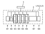
- FIG. 2 is a configuration explanatory view of a component mounting line included in the component mounting system of the embodiment.
- FIG. 3 is a plan view of an electronic component mounting device included in the component mounting system of the embodiment.
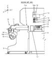
- FIG. 4 is a partial cross-sectional view of an electronic component mounting device included in the component mounting system of the embodiment.
- FIG. 5 is an explanatory diagram in which an electronic component mounting device included in the component mounting system of the embodiment simultaneously sucks a plurality of electronic components by a plurality of suction nozzles.
- FIG. 6A is a configuration explanatory view of a double feeder used in an electronic component mounting device included in the component mounting system of the embodiment.
- FIG. 6B is a configuration explanatory view of a triple stick feeder used in an electronic component mounting device included in the component mounting system of the embodiment.
- FIG. 7 is a block diagram showing the configuration of the management computer (setup change work support device) of the embodiment.
- FIG. 8 is an explanatory diagram of an example of component information used in the management computer (setup change work support device) of the embodiment.
- FIG. 9 is an explanatory diagram of an example of component arrangement information used in the management computer (setup change work support device) of the embodiment.
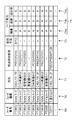
- FIG. 10 is an explanatory diagram of an example of feeder information used in the management computer (setup change work support device) of the embodiment.
- FIG. 11 is an explanatory diagram of an example of component location information used in the management computer (setup change work support device) of the embodiment.
- FIG. 12 is an explanatory diagram of an example of setup change component arrangement information created by the management computer (setup change work support device) of the embodiment.
- FIG. 13 is a diagram showing an example of a pickup instruction screen displayed on the touch panel of the mobile terminal included in the component mounting system of the embodiment.
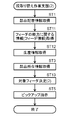
- FIG. 14 is a flow chart of the first setup change work support method of the embodiment.
- FIG. 15 is a flow chart of the second setup change work support method of the embodiment.
- the two axial directions orthogonal to each other in the horizontal plane are the X direction of the substrate transport direction (horizontal direction in FIG. 3) and the Y direction orthogonal to the substrate transport direction (vertical direction in FIG. 3). Is shown.
- the Z direction (vertical direction in FIG. 4) is shown as a height direction orthogonal to the horizontal plane.
- the Z direction is a vertical direction or an orthogonal direction when the electronic component mounting device is installed on a horizontal plane.
- the component mounting system 1 has a configuration in which three component mounting lines L1 to L3 arranged on the floor F are connected by a wired or wireless communication network 2 and managed by a management computer 3.
- the component mounting lines L1 to L3 are arranged in the production area Ap provided on the floor F.
- the component mounting lines L1 to L3 are configured by connecting a plurality of production facilities including a screen printing device and an electronic component mounting device as described later, and electronic components (hereinafter, simply referred to as "component D") are mounted on a substrate. It has a function to produce a mounted mounting board (product).
- the component mounting lines L1 to L3 included in the component mounting system 1 do not have to be three, and may be one, two, or four or more.
- the placement work support device 4 is arranged in the preparation area As, which is different from the production area Ap provided on the floor F.
- the placement work support device 4 is connected to the management computer 3 via the communication network 2.
- the arrangement work support device 4 includes a reader 4a that reads a label 19a (see FIG. 4) on which a bar code, a two-dimensional code, or the like attached to the reel 19 for storing the carrier tape 18 in a wound state is displayed.
- a replacement trolley 5, which is a target of the placement work described later, is connected to the placement work support device 4.
- a plurality of carriages 5 in various states such as before, during, or after the execution of the placement work are stored.
- a feeder maintenance device 6 connected to the management computer 3 via the communication network 2 is arranged.
- the feeder maintenance device 6 performs maintenance such as measuring the state of the attached tape feeder 11 (see FIG. 3) and adjusting the feed stop position.
- the maintenance result of the tape feeder 11 by the feeder maintenance device 6 is transmitted to the management computer 3.
- a storage shelf 7 is arranged for this purpose.
- the placement work support device 4 and the feeder maintenance device 6 arranged in the preparation area need not be one, and may be two or more. Further, the number of storage shelves 7 arranged in the preparation area As does not have to be one, and may be two or more.
- the carriage 5 connected to the placement work support device 4 is subjected to placement work (outer setup work) according to work instructions corresponding to the types of mounting boards to be produced in the component mounting lines L1 to L3. ..
- placement work the worker W removes the tape feeder 11 and the reel 19 for supplying the instructed part D from the carriage 5, the work of removing the carrier tape 18 from the tape feeder 11, and the reel 19 is stored in the tape feeder 11.
- the work of attaching the carrier tape 18 and the work of attaching the tape feeder 11 to the designated position of the trolley 5 are executed.
- the carrier tape 18 (reel 19) may be attached to and detached from the tape feeder 11 by the operator W by a detachable robot (not shown) provided with a parallel link or an articulated mechanism.
- a detachable robot (not shown) provided with a parallel link or an articulated mechanism.
- an automatic transfer robot (not shown) equipped with an articulated mechanism or the like executes attachment / detachment of the tape feeder 11 and the reel 19 to and from the carriage 5 and transportation of the tape feeder 11 and the reel 19 between the carriage 5 and the storage shelf 7. May be good.
- the worker W carries a mobile terminal T used for work.
- the mobile terminal T includes a terminal-side communication unit Ta that wirelessly communicates with the arrangement work support device 4 or the management computer 3 to exchange information, and a touch panel Tb having a display function and an input function. Further, the mobile terminal T is provided with a camera Tc on the surface opposite to the touch panel Tb.
- the mobile terminal T displays and processes various information received from the arrangement work support device 4 and displays it on the touch panel Tb. Further, the mobile terminal T recognizes the information of the label 19a captured by the camera Tc. Further, the mobile terminal T transmits various information input from the touch panel Tb, information on the recognized label 19a, and the like to the arrangement work support device 4 or the management computer 3.
- the tape feeder 11 when the tape feeder 11 is attached to the carriage 5 connected to the arrangement work support device 4, power is supplied from the arrangement work support device 4 to the tape feeder 11 via the carriage 5, and the tape feeder 11
- the built-in feeder control unit (not shown) is in a state of being able to communicate with the arrangement work support device 4.
- the dolly 5 is provided with a plurality of slots for mounting the tape feeder 11.
- the arrangement work support device 4 acquires information (feeder number) for identifying the tape feeder 11 from the feeder control unit of the tape feeder 11 mounted in the slot. Further, the placement work support device 4 acquires information for identifying the carriage 5 (trolley number) and information for identifying the slot in which the tape feeder 11 is mounted (slot number) from the carriage 5.
- the worker W reads the label 19a attached to the reel 19 with the reader 4a and assigns the acquired reel number to the placement work support device 4 or the management computer 3. Collate with the information stored in. Further, when the reel 19 is stored in the storage shelf 7 or when the reel 19 is taken out from the storage shelf 7, the worker W uses the mobile terminal T to read and collate the label 19a of the reel 19. As a result, it is possible to acquire the mounting status of the tape feeder 11 on the carriage 5, the mounting status of the reel 19 on the tape feeder 11, and the like.
- the arrangement work in the carriage 5 in the preparation area As including the carriage 5 connected to the arrangement work support device 4, the arrangement work can be executed in parallel with the production of the mounting boards on the component mounting lines L1 to L3.
- the setup change work for changing the product type outside the component mounting lines L1 to L3, including the arrangement work for the carriage 5, is referred to as an external setup work.
- the worker W moves the trolley 5 for which the placement work has been completed in the preparation area As to the component mounting lines L1 to L3 and mounts it on the electronic component mounting device. Perform the setup change work to replace the dolly 5 that has been installed.
- the worker W conveys the replacement screen mask, tape feeder 11, mounting head 14, suction nozzle 14b, reel 19, etc. stored in the preparation area As to the component mounting lines L1 to L3.
- Exchange the setup change work for changing the product type in the component mounting lines L1 to L3, including the setup change work for replacing the carriage 5, is referred to as an internal setup work.
- the component mounting lines L1 to L3 have the same configuration, and the component mounting lines L1 will be described below.
- the component mounting line L1 includes a board supply device M1, a screen printing device M2, electronic component mounting devices M3 to M6, a reflow device M7, and a board from the upstream side (left side of the paper surface) to the downstream side (right side of the paper surface) in the substrate transport direction. It is configured by connecting production equipment such as a recovery device M8 in series.
- the component mounting line L1 is a group of production facilities connected via the communication network 2, and the production facilities may not be physically connected to each other.
- the board supply device M1, the screen printing device M2, the electronic component mounting devices M3 to M6, the reflow device M7, and the board recovery device M8 are connected to the management computer 3 via the communication network 2.
- the board supply device M1 includes a storage unit such as a rack for storing a plurality of boards, and executes a board supply operation of supplying the board taken out from the storage unit to the device on the downstream side.
- the screen printing device M2 executes a solder printing operation of printing solder on a substrate carried in from the upstream side via a screen mask attached to the printing work unit.
- the electronic component mounting devices M3 to M6 execute the component mounting operation of mounting the component D on the board on which the solder is printed by the mounting head 14.
- the component mounting line L1 is not limited to the configuration of four electronic component mounting devices M3 to M6, and the electronic component mounting devices M3 to M6 may be one to three or five or more.
- the reflow device M7 heats the substrate carried into the device by the substrate heating unit, and executes a substrate heating operation of solder-bonding the electrode portion of the substrate and the component D.
- the board recovery device M8 includes a storage unit such as a rack for storing a plurality of boards, and executes a board recovery operation of receiving the boards carried out by the upstream device and collecting them in the storage unit.
- the electronic component mounting devices M3 to M6 have the same configuration, and the electronic component mounting device M3 will be described here.
- the electronic component mounting device M3 has a function of mounting the component D on the substrate B.
- a substrate transport mechanism 9 is installed in the X direction at the center of the base 8.
- the board transport mechanism 9 transports the board B carried in from the upstream side in the X direction, positions the board B at the mounting work position by the mounting head 14 described below, and holds the board B. Further, the board transfer mechanism 9 carries out the board B for which the component mounting work has been completed to the downstream side.
- Parts supply units 10 are installed on both sides of the board transfer mechanism 9.
- a carriage 5 on which a plurality of tape feeders 11 (feeders) are mounted in parallel in the X direction is attached to the component supply unit 10.
- the mounting head 14 is a component by feeding the carrier tape 18 having a pocket for storing the component D from the outside of the component supply unit 10 in the direction toward the substrate transport mechanism 9 (tape feed direction).
- the component D is supplied to the component supply position 11a from which the D is taken out.
- the tape feeder 11 can be arranged in the component supply unit 10 of the electronic component mounting devices M3 to M6 for mounting the component D (electronic component) on the substrate B (work), and is a feeder that supplies the component D.
- a plurality of tape feeders 11 are provided according to the width (8 mm, 16 mm, etc.) of the carrier tape 18 that can be mounted, the component size (1608, 0402, etc.) of the component D that can be supplied, the type (chip component, deformed component, etc.), and the like. Types are available.
- the feeder mounted on the trolley 5 may be a tray feeder that supplies the component D placed on the tray, a stick feeder that supplies the component D aligned and held on the hollow stick, or the like. ..
- Y-axis tables 12 provided with a linear drive mechanism are arranged at both ends in the X direction on the upper surface of the base 8.
- a beam 13 similarly provided with a linear mechanism is movably coupled to the Y-axis table 12 in the Y direction.
- a mounting head 14 is mounted on the beam 13 so as to be movable in the X direction.
- the mounting head 14 includes a plurality of (here, eight) nozzle units 14a. A plurality of types of mounting heads 14 having different numbers of nozzle units 14a and the like are prepared.
- a suction nozzle 14b that vacuum-sucks and holds the component D is attached to the lower end of each nozzle unit 14a.
- a plurality of types of suction nozzles 14b having different nozzle shapes and the like are prepared according to the size and shape of the component D to be sucked.
- Each nozzle unit 14a raises and lowers the suction nozzle 14b in the vertical direction (Z direction).
- the Y-axis table 12 and the beam 13 constitute a mounting head moving mechanism 15 that moves the mounting head 14 in the horizontal direction (X direction, Y direction).
- the mounting head moving mechanism 15 and the mounting head 14 pick up the component D from the component supply position 11a of the tape feeder 11 mounted on the component supply unit 10 by the suction nozzle 14b. Then, the mounting head moving mechanism 15 executes a component mounting operation that repeats a series of mounting turns in which the mounting head 14 is transferred to the mounting position of the board B held by the board transport mechanism 9 and mounted.
- the beam 13 is equipped with a head camera 16 which is located on the lower surface side of the beam 13 and moves integrally with the mounting head 14.
- the head camera 16 moves above the board B positioned at the mounting work position of the board transport mechanism 9 and images a board mark (not shown) provided on the board B. Recognizes the position of the substrate B.
- a component recognition camera 17 is installed between the component supply unit 10 and the board transfer mechanism 9.
- the component recognition camera 17 takes an image of the component D held by the suction nozzle 14b to recognize the holding position and the like.
- the mounting position is corrected in consideration of the recognition result of the board B by the head camera 16 and the recognition result of the component D by the component recognition camera 17.
- FIG. 4 a reel 19 around which a carrier tape 18 for accommodating a component D is wound is held on the front side of the carriage 5.
- the tape feeder 11 conveys the carrier tape 18 stored in the reel 19 in the tape feed direction and supplies the component D to the component take-out position by the mounting head 14.
- a label 19a is attached to the reel 19.
- FIG. 5 shows four nozzle units 14a arranged in the direction in which the tape feeders 11 are arranged (X direction) among the eight nozzle units 14a included in the mounting head 14.
- the tape feeder 11 and the nozzle unit 14a are installed at the same interval, and the component D is supplied to each component supply position 11a.
- the double feeder 20 (feeder) mounted on the carriage 5 will be described with reference to FIG. 6A.
- the double feeder 20 has two sets of tape transport mechanisms for transporting the carrier tape 18.
- the back surface 20a of the double feeder 20 is formed with an insertion port 20b for inserting the carrier tape 18A stored in the reel 19A and an insertion port 20c for inserting the carrier tape 18B stored in the reel 19B.
- Two component supply positions 20e and 20f are formed on the upper surface 20d of the double feeder 20.
- the two sets of tape transfer mechanisms independently convey the two carrier tapes 18A and 18B. As a result, the component D stored in the carrier tape 18A is supplied to the component supply position 20e, and the component D stored in the carrier tape 18B is supplied to the component supply position 20f.
- the triple stick feeder 21 receives the parts D stored in the stick cases 22A, 22B, and 22C, respectively, and conveys and supplies the parts D to the parts supply positions 21a, 21b, and 21c, respectively, of the three sets of component transfer mechanisms 21d, 21e, and 21f. It has.
- the parts transport mechanism 21d stores the part D stored in the stick case 22A at the parts supply position 21a
- the parts transport mechanism 21e stores the parts D stored in the stick case 22B at the parts supply position 21b
- the parts transport mechanism 21f stores the parts D stored in the stick case 22C.
- the component D to be used is independently supplied to the component supply position 21c.
- the components D supplied by the double feeder 20 to the two component supply positions 20e and 20f may be the same or different. Further, the components D supplied by the triple stick feeder 21 to the three component supply positions 21a, 21b, 21c may be the same or different. As described above, the double feeder 20 and the triple stick feeder 21 are multi-feeders capable of supplying a plurality of types of components D (electronic components).
- the management computer 3 includes a processing unit 30, a storage unit 31 which is a storage device, an input unit 32, and a display unit 33.
- the processing unit 30 is a data processing device such as a CPU (central processing unit), and has a feeder information acquisition unit 34, a component location information acquisition unit 35, a production information acquisition unit 36, a production history acquisition unit 37, and maintenance information as internal processing units. It includes an acquisition unit 38, a feeder evaluation unit 39, a target feeder determination unit 40, and a pickup instruction unit 41.
- the input unit 32 is an input device such as a keyboard, a touch panel, and a mouse, and is used when inputting an operation command or data.
- the display unit 33 is a display device such as a liquid crystal panel, and in addition to displaying various data stored in the storage unit 31, various information such as an operation screen for operation by the input unit 32 is displayed.
- the management computer 3 does not have to be configured by one computer, and may be configured by a plurality of devices. For example, all or part of the storage device may be provided in the cloud via a server.
- the production plan information 42 stores a production plan including information for specifying the number of production sheets, the scheduled production date and time, and the component mounting lines L1 to L3 for producing the mounting board for each type of mounting board to be produced.
- the product type information 43 stores information necessary for component mounting work, such as the component name and mounting position of the component D (electronic component) mounted on the substrate B, for each product type of the mounting board.
- the component information 44 information on electrical characteristics, component size, supply means (information such as carrier tape 18, stick case 22, tray and other supply means, as well as carrier tape width) and the like are provided for each component name of component D. It is remembered.
- the component placement information 45 stores the placement information of the components D in the electronic component mounting devices M3 to M6 for each type of mounting board.
- the component information 44 includes a component name 61, an electrical characteristic 62, a component size 63, and a supply means 64.
- the part name 61 is information that identifies the part D.
- the electrical characteristic 62 in addition to the electrical characteristics such as the resistance and capacitance of the component D, the type (function) of the component D such as a microcomputer and a memory is stored.
- the component size 63 the size of the chip component (0201 or the like) and the size of the QFP (Quad Flat Package) component (20 mm ⁇ 20 mm or the like) are stored.
- the supply means 64 in addition to the method of storing the component D (carrier tape 18, stick case 22, etc.), the tape width (8 mm, 16 mm, etc.) in the case of the carrier tape 18 is stored.
- the component arrangement information 45 stores the arrangement of the component D, which is created in advance based on the product type information 43 and the like.
- the component arrangement information 45 includes a line name 65, a supply position 66, a slot number 67, a component name 61, a supply method 68, and a feeder number 69.
- the line name 65 is information for specifying the component mounting lines L1 to L3, and “L2” indicates the component mounting line L2.
- the supply position 66 is information for specifying the positions (front side or rear side) of the electronic component mounting devices M3 to M6 and the component supply unit 10, and “# 1F” is the component on the front side of the electronic component mounting device M3 (# 1).
- the supply unit 10 is shown.
- Slot number 67 indicates the position of the slot of the carriage 5 on which the tape feeder 11 or the like is mounted.
- the part name 61 is information that identifies the part D supplied from that position, and is the same as the part name 61 of the part information 44. That is, the component arrangement information 45 is associated with the component information 44 via the component name 61.
- the supply method 68 indicates the type of feeder arranged at that position. “Tape” is the tape feeder 11, “double feeder” is the double feeder 20, and “stick” is the stick feeder (triple stick feeder 21). ). Further, “tape (simultaneous)" indicates that the tape feeder 11 is the target of simultaneous adsorption.
- the feeder number 69 indicates information that identifies the feeder to be mounted at that position. In FIG. 9, since the target feeder has not been assigned, all the feeder numbers 69 are blank.
- the feeder information acquisition unit 34 is a component D (electronic component) from the electronic component mounting devices M3 to M6 included in the component mounting lines L1 to L3, the placement work support device 4, the mobile terminal T used by the worker W, and the like.
- Information on the status of the feeder that supplies the feeder is acquired and stored in the storage unit 31 as the feeder information 46.
- the component location information acquisition unit 35 is the location of the component D to be mounted on the mounting board from the electronic component mounting devices M3 to M6 provided in the component mounting lines L1 to L3, the placement work support device 4, the mobile terminal T used by the worker W, and the like.
- Information about the above is acquired and stored in the storage unit 31 as the component location information 47.
- the feeder information 46 and the component location information 47 are updated every time the location of the feeder, the mounting state of the component D, and the location of the component D change due to the external setup work or the internal setup work.
- the feeder information 46 includes a feeder number 69, a feeder type 70, a location 71, a component mounting state 72, a planned use 73, and a feeder capacity 74.
- the feeder number 69 is information for identifying the feeder, and is the same as the feeder number 69 of the component arrangement information 45. That is, the feeder information 46 is associated with the component arrangement information 45 via the feeder number 69.
- the feeder type 70 indicates the type of feeder.
- the "8 mm tape” is a tape feeder 11 that conveys a carrier tape 18 having a width of 8 mm
- the "double feeder” is a double feeder 20
- the "triple stick” is a triple stick. It shows that it is a stick feeder 21.
- Location 71 indicates the location of the feeder.
- the "C42 / L1 / # 1R” is mounted on the trolley 5 having the trolley number "C42” mounted on the component supply unit 10 on the rear side of the electronic component mounting device M3 (# 1) of the component mounting line L1. It shows that it is.
- “C73 / preparation area” indicates that the dolly number in the preparation area As is attached to the dolly 5 of "C73”.
- “storage shelf / S05” indicates that the shelf number 76 (see FIG. 11) of the storage shelf 7 in the preparation area As is stored in the shelf of "S05".
- the tape feeder 11 having the feeder number 69 of "FT0804" is a storage shelf with the carrier tape 18 having the part name 61 stored in the reel 19 having the reel number 75 of "R303" and the carrier tape 18 containing the "PC01" attached. It shows that it is stored in 7. Further, the tape feeder 11 having the feeder number 69 of "FT0805” indicates that the carrier tape 18 is stored in the storage shelf 7 in a removed state.
- the usage schedule 73 is information regarding the usage schedule of the feeder, and the product number of the mounting board is stored when the next reservation is made, and “-” is stored when the next reservation is not made. ing.
- the tape feeder 11 having the feeder number 69 of "FT0802" has a reservation to be used for the production of the mounting board having the product number "B112" next.
- the feeder capacity 74 is information on the capacity of the feeder, and in this example, the accuracy 74a, the speed 74b, and the success rate 74c are displayed as S, A, B, and C.
- the accuracy 74a indicates the variation in the feed stop position when the feeder supplies the component D to the component supply position.
- the speed 74b indicates the effective speed at which the feeder supplies the component D to the component supply position.
- the success rate 74c indicates the probability that the component D supplied by the feeder can be sucked to the suction nozzle 14b (probability of not making a suction error).
- the feeder may have a large variation in stop position, a slow effective speed, and an increase in suction errors.
- the feeder capacity 74 does not necessarily have to be displayed in categories such as S, A, B, and C, and may be specific numerical values such as variation, effective speed, and success rate.
- the feeder information 46 includes information on the location of the feeder (location 71), information on the mounting state of the electronic component (component D) supplied by the feeder (part mounting information 62), and information on the usage schedule of the feeder (use). It contains information about feeder information such as Schedule 73). Further, the feeder information 46 relates to the ability of the feeder such as information on the feed stop position of the feeder (accuracy 74a) and information on whether or not the feeder is a multi-feeder capable of supplying a plurality of types of electronic components (feeder type 70). Contains information.
- the part location information 47 includes a part name 61, a reel number 75, a feeder number 69, and a shelf number 76.
- the part name 61 is the same as the part name 61 of the part information 44.
- the reel number 75 is information for identifying the reel 19 in which the part D of the part name 61 is stored, and is the same as the reel number 75 included in the part mounting state 72 of the feeder information 46.
- the part D having the reel number 75 “ ⁇ ” indicates that the component D is stored in a means other than the reel 19 such as the stick case 22.
- the stick case number is stored in the reel number 75 column.
- the feeder number 69 is the same as the feeder number 69 of the feeder information 46.
- the shelf number 76 is information for specifying the position of the shelf provided on the storage shelf 7 in the preparation area As, and is the same as the shelf number 76 included in the location 71 of the feeder information 46.
- the component D attached to the feeder is associated with the feeder information 46 by the feeder number 69, and the location 71 of the component D is specified by the location 71 included in the feeder information 46. Further, the location of the component D that is not attached to the feeder is specified by the shelf number 76.
- the production information acquisition unit 36 acquires (collects) information related to the production of the work (mounting board) from various information stored in the storage unit 31, and stores it in the storage unit 31 as the production information 48. Specifically, the production information acquisition unit 36 acquires information on the priority for producing the product type (hereinafter, referred to as “target product type”) of the mounting substrate to be produced on the component mounting lines L1 to L3 from the production plan information 42. To do.
- the production information acquisition unit 36 acquires information on the component size 63 of the electronic component (component D) mounted on the target product from the product information 43 and the component information 44. Further, the production information acquisition unit 36 acquires information on the number of electronic components used for producing the target product from the production plan information 42 and the product product information 43. Further, the production information acquisition unit 36 acquires information on the component arrangement of the electronic components used for the production of the target product type from the component arrangement information 45.
- the production history acquisition unit 37 acquires information on various errors generated in the production of the mounting board in the production equipment constituting the component mounting lines L1 to L3, information on the correction value, and the like, and stores the information as the production history information 49.
- the production history acquisition unit 37 detects a suction error in which the suction nozzle 14b could not hold the component D, a mounting error in which the component D could not be mounted on the substrate B, and a component D from the electronic component mounting devices M3 to M6. Acquire the correction value of the mounting position when mounting on the board B.
- the maintenance information acquisition unit 38 acquires information on the state of the tape feeder 11 from the feeder maintenance device 6 and stores it in the storage unit 31 as maintenance information 50.
- the feeder evaluation unit 39 varies in the feed stop position of the feeder (accuracy 74a) and supplies the component D to the component supply position based on the production history information 49 and the maintenance information 50 stored in the storage unit 31. 74b), the feeder capacity (feeder capacity 74) including the success rate (success rate 74c) of normally adsorbing the component D supplied by the feeder is evaluated, and the feeder capacity 74 of the feeder information 46 is updated.
- the feeder evaluation unit 39 determines the feeder capacity 74 based on the frequency of suction errors, the magnitude and variation of the correction value of the mounting position, the frequency of use of the feeder, the elapsed time from maintenance, and the like.
- the target feeder determination unit 40 refers to a feeder used for production of the target product type (hereinafter, referred to as “target feeder”) based on the component arrangement information 45, the feeder information 46, the component location information 47, and the production information 48. ) Is determined, and the arrangement in the component supply unit 10 is determined.
- the target feeder determination unit 40 determines the target feeder and its arrangement, the target feeder determination unit 40 creates the component arrangement information 45 for the setup change work by updating (or newly designating) the feeder number 69 in the component arrangement information 45 of the target product type. It is stored in the storage unit 31 as the setup change component arrangement information 51.
- FIG. 12 shows an example of the setup change part arrangement information 51 created for performing the external setup work on the trolley 5 having the trolley number “C73”, and is attached to the feeder in addition to the information included in the part arrangement information 45.
- the reel number 75 of the reel 19 for storing the carrier tape 18 to be used is also stored.
- the setup change component arrangement information 51 is created not only for each carriage 5 but also for each component mounting line L1 to L3.
- the target feeder includes a reusable feeder in which the feeder on which the component D is mounted is mounted on the trolley 5 as it is, and a component D in which the component D is not mounted or is mounted and a new component D is mounted. There is a newly installed feeder. If there is a reusable feeder available, the target feeder determination unit 40 preferentially allocates the reusable feeder to the target feeder.
- the target feeder determination unit 40 does not have a feeder satisfying the required feeder capacity 74 in the newly installed feeder and is in the reused feeder, the target feeder determination unit 40 does not assign the reused feeder as it is to the target feeder, but uses it as a newly installed feeder. assign. That is, it is determined that the mounted component D is removed from the reuse feeder, and the component D is newly mounted as a newly mounted feeder and mounted on the trolley 5.
- assign that is, it is determined that the mounted component D is removed from the reuse feeder, and the component D is newly mounted as a newly mounted feeder and mounted on the trolley 5.
- the target feeder determination unit 40 includes a first determination unit 40a and a second determination unit 40b as internal processing units.
- the first determination unit 40a determines the target feeder based on the information regarding the location of the feeder (location 71) included in the feeder information 46. Specifically, when there are a plurality of candidate target feeders, the first determination unit 40a preferentially selects from the feeders closest to the place where the worker W performs the work. For example, when performing external setup work on a trolley 5 connected to the placement work support device 4, the trolley 5 has a high priority, and the other trolleys 5, storage shelves 7, and parts mounting in the preparation area As are hereinafter described. The priority is lowered in the order of lines L1 to L3. As a result, the moving distance of the worker W can be shortened.
- the first determination unit 40a determines the target feeder based on the information regarding the mounting state of the electronic component (component D) included in the feeder information 46 (component mounting state 72). Specifically, in the first determination unit 40a, the priority of the reuse feeder is set higher than that of the newly mounted feeder, and the priority of the feeder to which the component D is not mounted is set to the priority of the newly mounted feeder. Make it higher than the feeder you have. As a result, the work of removing the unused component D from the feeder can be reduced.
- the first determination unit 40a determines the target feeder based on the information regarding the feeder usage schedule (usage schedule 73) included in the feeder information 46. Specifically, the first determination unit 40a excludes feeders scheduled to be used in other target varieties from the target feeders. This prevents the reserved feeder from being accidentally used for other productions.
- the part D whose part name 61 is "PR01" supplied from the slot whose slot number 67 is “1” in FIG. 12 is attached to the tape feeder 11 whose feeder number 69 is "FT0802" in FIG. If the tape feeder 11 is installed in the slot "1" as a reuse feeder, work efficiency is good. However, since it is input to the usage schedule 73 that the tape feeder 11 is used for the production of the mounting substrate of the corresponding type "B112", the first determination unit 40a is excluded from the target feeder.
- the second determination unit 40b when determining the target feeder, the second determination unit 40b together determines the target feeders of a plurality of target varieties including the target varieties scheduled to be produced next. That is, the second determination unit 40b produces the target product based on the information on the feeder capacity (feeder capacity 74) included in the feeder information 46 and the information on the priority for producing the target product product included in the production information 48.
- the feeder with the appropriate capacity is preferentially assigned to the production of the target varieties with high priority.
- the second determination unit 40b preferentially assigns a feeder having a high feeder capacity 74 such as a speed 74b and a success rate 74c to a target product having a high priority because there is little margin in production time. As a result, the production capacity of the target varieties with high priority can be increased.
- the second determination unit 40b mounts a large number of electronic components based on the feeder capacity 74 and the information on the number of electronic components (component D) used for the production of the target product product included in the production information 48.
- the feeder with the appropriate capacity is preferentially assigned to the electronic components that are used frequently.
- the second determination unit 40b preferentially allocates a feeder having a high speed 74b to the component D which is frequently used. Thereby, even when one feeder supplies the component D to the plurality of suction nozzles 14b in the same mounting turn, it is possible to prevent the mounting time from increasing by allocating the feeder having a high speed 74b.
- the second determination unit 40b determines that the electronic component having a small component size 63 is based on the feeder capacity 74 and the information regarding the component size 63 of the electronic component (component D) mounted on the target product type included in the production information 48.
- a feeder with a capability suitable for mounting is preferentially assigned to an electronic component having a component size 63.
- the second determination unit 40b preferentially assigns a feeder having a high accuracy 74a to a component D having a small component size 63. As a result, it is possible to suppress the occurrence of a suction error in which the suction nozzle 14b cannot suck the small component D.
- the second determination unit 40b allocates a feeder having an accuracy of 74a of "S” to this component D in FIG.
- the feeder numbers 69 are “FT0802” and “FT0804”, and the accuracy 74a of the two feeders is “S”.
- the second determination unit 40b allocates the "FT0804" to the slot of the "1". Since "FT0804" is a newly mounted feeder, the second determination unit 40b allocates the component D whose reel number 75 is "R801".
- the second determination unit 40b has information on feed stop positions of a plurality of feeders (accuracy 74a) and information on component arrangement of electronic components (component D) used for production of the target product type included in the production information 48. Based on the above, a plurality of feeders having a small difference in feed stop positions are preferentially assigned to a plurality of electronic components that can be simultaneously attracted by the plurality of suction nozzles 14b that suck the electronic components. As a result, when the plurality of suction nozzles 14b simultaneously suck the component D, it is possible to suppress variations in the suction position of the component D and the occurrence of suction errors.
- the second determination unit 40b assigns a feeder having an accuracy of 74a of "S" or "A” as a target feeder to be mounted in the slots "6" to "9".
- the feeder number 69 is “FT0803”
- the part name 61 is “PR02”
- “FT0807” is a reuse feeder equipped with “PR52”
- the accuracy 74a is “A”. Therefore, the second determination unit 40b assigns "FT0803" to the slot "6" and "FT0807” to the slot "7".
- the feeder number 69 “FT0805” is a newly mounted feeder to which the component D is not mounted, but the accuracy 74a is “B”. Therefore, the second determination unit 40b is excluded from the target feeders for simultaneous suction. .. Then, the second determination unit 40b allocates "FT0806" having the accuracy 74a of "A” to the slot of "8” and “FT0808” to the slot of "9". Further, since "FT0806" and "FT0808” are newly installed feeders, the second determination unit 40b allocates the part D of the reel number 75 of the storage shelf 7 to the part D of the reel number "R222" and the part D of the "R662", respectively.
- the second determination unit 40b is a multi-feeder for electronic components to which the multi-feeder can be applied, based on information on whether or not the multi-feeder can supply a plurality of types of electronic components (feeder type 70). Is preferentially assigned.
- the supply method 68 is the “double feeder” for the slots whose slot numbers 67 are “2L” and “2R”
- the second determination unit 40b has the feeder numbers 69 in the slots “2L” and “2R”. Allocates the double feeder 20 of "FD005".
- the supply method 68 is a "stick" for the slots "3" to "5"
- the second determination unit 40b has a triple feeder number 69 of "FS111" in the slots "3" to "5". Allocate the stick feeder 21.
- the target feeder determination unit 40 (first determination unit 40a) is arranged in the parts supply unit 10 and uses the target feeder for the production of the target product product based on the information regarding the status of the feeder (feeder information 46). decide. As a result, it is possible to support the efficient work of setting up the feeder. Further, the target feeder determination unit 40 (second determination unit 40b) relates the target feeder, which is arranged in the parts supply unit 10 and used for the production of the target product type, to information on the feeder capacity (feeder capacity 74) and the production of the work. The decision is made based on the information (production information 48). As a result, it is possible to support the setup change of the feeder so that the work can be performed in consideration of the production plan, production efficiency and quality of the mounted board to be manufactured.
- the pickup instruction unit 41 gives an instruction to pick up the target feeder and the part D (reel 19, stick case 22, etc.) based on the information on the location of the feeder (location 71) and the shelf number 76. Further, the pickup instruction unit 41 is related to work related to removal of the electronic component from the target feeder or attachment of the electronic component to the target feeder based on the information regarding the mounting state of the electronic component (component D) (component mounting state 72). Give instructions including work.
- the pick-up instruction unit 41 causes the work instruction to be displayed on the mobile terminal T carried by the worker W or the display unit of the arrangement work support device 4.
- the pickup instruction unit 41 when the pickup instruction unit 41 gives a work instruction to the robot, the pickup instruction unit 41 transmits the instruction to the robot by using radio or the like. At that time, when the target feeder is picked up by the robot, the pickup instruction unit 41 instructs the target feeder to pick up only the target feeder that can be picked up by the robot. For example, when the target feeder is located on the shelf of the storage shelf 7 that the robot cannot pick up, the target feeder is excluded from the targets picked up by the robot.
- FIG. 13 shows a pickup instruction of the target feeder (feeder number: FT0804) in which the slot number 67 of the setup change component arrangement information 51 shown in FIG. 12 is mounted in “1”.
- a “target product” display frame 81, a “target feeder” display frame 82, a “pickup instruction” display frame 83, and an “OK” button 84 are displayed on the pickup instruction screen 80.
- the product type name (B110) of the mounting board to be set up is displayed.
- the feeder number 69 (FT0804) of the target feeder which is the target of the pickup instruction, is displayed in the “target feeder” display frame 82.
- the pickup instruction is displayed for each process. That is, in the step (1), it is instructed that the target feeder (FT0804) is taken out from the shelf number 76 of the storage shelf 7 from “S05”. In step (2), it is instructed to install the target feeder (FT0804) in the slot where the slot number 67 of the carriage 5 having the carriage number “C73” is “1”. In step (3), it is instructed to remove the component D (part name 61 is “PC01” and reel number 75 is “R303”) currently mounted on the target feeder (FT0804). That is, the step (3) is an instruction of work relating to the removal of the electronic component (component D) from the target feeder.
- step (4) it is instructed that the part D (part name 61 is “PR01” and reel number 75 is “R801”) is taken out from the shelf number 76 of the storage shelf 7 from “S03”. ..
- step (5) it is instructed to attach the component D taken out from the storage shelf 7 to the target feeder (FT0804). That is, the step (5) is an instruction of the work related to the attachment of the electronic component (component D) to the target feeder.
- the worker W operates the "OK" button 84, a pickup instruction for the next target feeder is displayed.
- the feeder information acquisition unit 34 that acquires information on the feeder status (feeder information 46) and the target feeder determination unit 40 (first determination unit 40a) that determines the target feeder based on the information on the feeder status.
- the management computer 3 including the above is a setup change work support device. As a result, it is possible to support the efficient work of setting up the feeder.
- the feeder information acquisition unit 34 for acquiring information on the capacity of the feeder (feeder information 46), the production information acquisition unit 36 for acquiring information on the production of the work (mounting board) (production information 48), and the target feeder as the feeder.
- the management computer 3 including the target feeder determination unit 40 (first determination unit 40a) for determining based on the information regarding the ability of the work and the information regarding the production of the work is a setup change work support device. As a result, it is possible to support the setup change of the feeder so that the work can be performed in consideration of the production plan, production efficiency and quality of the mounted board to be manufactured.
- the processing unit 30 acquires the component placement information 45 (ST1: component placement information acquisition step).
- the feeder information acquisition unit 34 acquires information (feeder information 46) regarding the status of the feeder (ST2: first feeder information acquisition step).
- the component location information acquisition unit 35 acquires the component location information 47 (ST3: component location information acquisition process).
- the first determination unit 40a determines the target feeder used for the production of the target product based on the component arrangement information 45 and the information on the feeder status (feeder information 46) (ST4: first. 1 Target feeder determination process).
- first target feeder determination step information on the location of the feeder included in the feeder information 46 (location 71), information on the mounting state of the electronic component (part D) (part mounting state 72), and the scheduled use of the feeder.
- the target feeder is determined based on the information regarding (planned use 73).
- the pickup instruction unit 41 gives an instruction to pick up the target feeder based on the component location information 47 and the information regarding the location of the feeder (feeder information 46) (ST5: pickup instruction step).
- the pickup instruction process when the target feeder is picked up by the robot, only the target feeders that can be picked up by the robot are instructed to be picked up. Further, in the pickup instruction process, based on the information on the mounting state of the electronic component (part mounting state 72), an instruction including a work related to removing the electronic component from the target feeder or a work related to mounting the electronic component to the target feeder is given. Do. As a result, it is possible to support the efficient work of setting up the feeder.
- the timing for determining the target feeder is such that the manager plans the daily production plan even immediately before the worker W starts the setup change work for the target product. It may be time to decide.
- a plurality of setup change component arrangement information 51 corresponding to the plurality of target varieties produced on that day are created. Then, when the setup change work is started based on the setup change part arrangement information 51 created in advance, if there is a feeder or part D whose location is different from that of the setup change part arrangement information 51, the first feeder information is again obtained.
- the setup change work is finally determined by executing the first target feeder determination step (ST4) from the acquisition process (ST2).
- the second setup change work support method differs from the first setup change work support method in that the target feeder is determined based on the information on the ability of the feeder (feeder ability 74).
- the same steps as those of the first setup change work support method are designated by the same reference numerals, and detailed description thereof will be omitted.
- the component placement information acquisition process (ST1) is executed.
- the feeder information acquisition unit 34 acquires information (feeder information 46) regarding the ability of the feeder (ST11: second feeder information acquisition step).
- the production information acquisition unit 36 acquires information (production information 48) related to the production of the work (mounting board) (ST12: production information acquisition process).
- the component location information acquisition step (ST3) is executed.
- the second determination unit 40b target feeder determination unit 40 sets the target feeder based on the information regarding the capacity of the feeder (feeder capacity 74 included in the feeder information 46) and the information regarding the production of the work (production information 48). Determine (ST13: second target feeder determination step).
- the pickup instruction step (ST5) is executed.
- the feeder having the ability suitable for the production of the target variety is the target variety having a high priority. Priority is given to production. Further, in the second target feeder determination step (ST13), it is suitable for mounting an electronic component having a small component size 63 based on the information regarding the component size 63 of the electronic component mounted on the target product type included in the production information 48. The capacity feeder is preferentially assigned to electronic components with a component size 63. Further, in the second target feeder determination step (ST13), the ability suitable for mounting a large number of electronic components is based on the information on the number of electronic components used for the production of the target product included in the production information 48. Feeder is preferentially assigned to the most used electronic components.
- the second target feeder determination step (ST13) the information regarding the component arrangement of the electronic parts used for the production of the target product included in the production information 48 and the information regarding the feed stop positions of the plurality of feeders included in the feeder information 46 Based on (feeder capacity 74), a plurality of feeders having a small difference in feed stop positions are preferentially assigned to a plurality of electronic components that can be simultaneously sucked by the plurality of suction nozzles 14b that suck the electronic components. Further, in the second target feeder determination step (ST13), information on whether or not the multi-feeder (double feeder 20, triple stick feeder 21) capable of supplying a plurality of types of electronic components included in the feeder information 46 is used. Based on (Feeder type 70), the multi-feeder is preferentially assigned to the electronic components to which the multi-feeder can be applied.
- the multi-feeder double feeder 20, triple stick feeder 21
- the target feeders of a plurality of target varieties including the target varieties scheduled to be produced next are determined together. In this way, it is possible to support the setup change of the feeder so that the work can be performed in consideration of the production plan, production efficiency and quality of the mounted mounting board to be manufactured.
- the feeder information 46 includes information on the feeder status (location 71, component mounting state 72, planned use 73) and information on the feeder capacity (feeder capacity 74).
- the structure of the file is not limited to this.
- information about the status of the feeder and information about the capabilities of the feeder may be in separate files.
- the component information 44 may be combined with the feeder information 46.
- the format of the file stored in the storage unit 31 can be changed as appropriate.
- the setup change work support method and the setup change work support device of the present disclosure have an effect that the setup change of the feeder can be supported so that the work can be performed in consideration of the production plan, production efficiency and quality of the mounting board to be manufactured. It is useful in the field of mounting electronic components on a substrate.
Landscapes
- Engineering & Computer Science (AREA)
- Manufacturing & Machinery (AREA)
- Microelectronics & Electronic Packaging (AREA)
- General Engineering & Computer Science (AREA)
- Quality & Reliability (AREA)
- Physics & Mathematics (AREA)
- General Physics & Mathematics (AREA)
- Automation & Control Theory (AREA)
- Operations Research (AREA)
- Supply And Installment Of Electrical Components (AREA)
Priority Applications (4)
| Application Number | Priority Date | Filing Date | Title |
|---|---|---|---|
| CN202080044794.5A CN114080869B (zh) | 2019-07-18 | 2020-05-28 | 换产调整作业辅助方法以及换产调整作业辅助装置 |
| US17/622,906 US12137525B2 (en) | 2019-07-18 | 2020-05-28 | Feeder setup change method and component mounting device for supporting feeder setup change method |
| JP2021532711A JPWO2021010033A1 (https=) | 2019-07-18 | 2020-05-28 | |
| JP2024098818A JP7821996B2 (ja) | 2019-07-18 | 2024-06-19 | 段取り替え作業支援方法および段取り替え作業支援装置 |
Applications Claiming Priority (2)
| Application Number | Priority Date | Filing Date | Title |
|---|---|---|---|
| JP2019132426 | 2019-07-18 | ||
| JP2019-132426 | 2019-07-18 |
Publications (1)
| Publication Number | Publication Date |
|---|---|
| WO2021010033A1 true WO2021010033A1 (ja) | 2021-01-21 |
Family
ID=74210502
Family Applications (1)
| Application Number | Title | Priority Date | Filing Date |
|---|---|---|---|
| PCT/JP2020/021202 Ceased WO2021010033A1 (ja) | 2019-07-18 | 2020-05-28 | 段取り替え作業支援方法および段取り替え作業支援装置 |
Country Status (4)
| Country | Link |
|---|---|
| US (1) | US12137525B2 (https=) |
| JP (2) | JPWO2021010033A1 (https=) |
| CN (1) | CN114080869B (https=) |
| WO (1) | WO2021010033A1 (https=) |
Cited By (1)
| Publication number | Priority date | Publication date | Assignee | Title |
|---|---|---|---|---|
| WO2023062680A1 (ja) * | 2021-10-11 | 2023-04-20 | 株式会社Fuji | 管理装置、および管理方法 |
Families Citing this family (2)
| Publication number | Priority date | Publication date | Assignee | Title |
|---|---|---|---|---|
| WO2021241389A1 (ja) * | 2020-05-29 | 2021-12-02 | パナソニックIpマネジメント株式会社 | 部品装着装置および部品装着方法 |
| CN118104410A (zh) * | 2021-10-22 | 2024-05-28 | 株式会社富士 | 信息处理装置、安装系统以及信息处理方法 |
Citations (6)
| Publication number | Priority date | Publication date | Assignee | Title |
|---|---|---|---|---|
| JPH03120897A (ja) * | 1989-10-04 | 1991-05-23 | Matsushita Electric Ind Co Ltd | 部品供給ユニットとこれを用いた電子部品実装機 |
| JP2005216965A (ja) * | 2004-01-27 | 2005-08-11 | Yamaha Motor Co Ltd | 実装機における段取り作業支援方法および同装置 |
| WO2014041640A1 (ja) * | 2012-09-12 | 2014-03-20 | 富士機械製造株式会社 | 生産順序最適化方法および生産順序最適化システム |
| JP2017045744A (ja) * | 2015-08-24 | 2017-03-02 | 富士機械製造株式会社 | 基板の生産方法 |
| JP2018056583A (ja) * | 2017-11-29 | 2018-04-05 | 富士機械製造株式会社 | 電子部品装着装置 |
| JP2018110188A (ja) * | 2017-01-05 | 2018-07-12 | パナソニックIpマネジメント株式会社 | 部品実装システムおよび部品供給装置の評価方法 |
Family Cites Families (16)
| Publication number | Priority date | Publication date | Assignee | Title |
|---|---|---|---|---|
| US6275744B1 (en) * | 1997-08-01 | 2001-08-14 | Kokusai Electric Co., Ltd. | Substrate feed control |
| JP3877501B2 (ja) * | 2000-07-07 | 2007-02-07 | 松下電器産業株式会社 | 部品認識データ作成方法及び作成装置並びに電子部品実装装置及び記録媒体 |
| US6862803B2 (en) * | 2000-08-29 | 2005-03-08 | Matsushita Electric Industrial Co., Ltd. | Method for mounting electronic component |
| JP2005216945A (ja) * | 2004-01-27 | 2005-08-11 | Yamaha Motor Co Ltd | フィーダ配置設定方法および同装置 |
| JP5403465B2 (ja) * | 2009-08-27 | 2014-01-29 | 日東工業株式会社 | 電子部品供給装置 |
| JP5615081B2 (ja) * | 2010-07-26 | 2014-10-29 | 富士機械製造株式会社 | 部品実装装置 |
| JP5877748B2 (ja) * | 2012-03-29 | 2016-03-08 | 富士機械製造株式会社 | フィーダの配置位置決定方法 |
| JP6091167B2 (ja) * | 2012-11-09 | 2017-03-08 | ヤマハ発動機株式会社 | フィーダ段取支援装置、フィーダ段取支援方法、フィーダ段取支援プログラム、記録媒体 |
| CN105474769B (zh) * | 2013-08-21 | 2018-12-21 | 株式会社富士 | 供料器元件种类决定方法及供料器元件种类决定装置 |
| EP3226669B1 (en) * | 2014-11-26 | 2020-01-22 | FUJI Corporation | Tool exchange assistance system and tool exchange assistance method for component mounting line |
| JP2016146381A (ja) | 2015-02-06 | 2016-08-12 | パナソニックIpマネジメント株式会社 | 段取り替え作業の指示方法 |
| KR102061155B1 (ko) * | 2015-04-03 | 2019-12-31 | 야마하하쓰도키 가부시키가이샤 | 셋업 지원 장치, 부품 실장기, 셋업 지원 방법 |
| US10806037B2 (en) * | 2017-01-05 | 2020-10-13 | Panasonic Intellectual Property Management Co., Ltd. | Component mounting system |
| JP6496915B2 (ja) * | 2017-03-23 | 2019-04-10 | パナソニックIpマネジメント株式会社 | 部材準備方法および部材準備装置 |
| DE112017008050T5 (de) * | 2017-10-31 | 2020-06-18 | Yamaha Hatsudoki Kabushiki Kaisha | Zufuhreinrichtungsverwaltungsvorrichtung und bauteilmontagesystem, das mit dieser versehen ist |
| JP6767641B2 (ja) * | 2019-02-07 | 2020-10-14 | パナソニックIpマネジメント株式会社 | 部品実装ラインにおける部品補給支援方法および部品補給支援システム |
-
2020
- 2020-05-28 JP JP2021532711A patent/JPWO2021010033A1/ja active Pending
- 2020-05-28 WO PCT/JP2020/021202 patent/WO2021010033A1/ja not_active Ceased
- 2020-05-28 CN CN202080044794.5A patent/CN114080869B/zh active Active
- 2020-05-28 US US17/622,906 patent/US12137525B2/en active Active
-
2024
- 2024-06-19 JP JP2024098818A patent/JP7821996B2/ja active Active
Patent Citations (6)
| Publication number | Priority date | Publication date | Assignee | Title |
|---|---|---|---|---|
| JPH03120897A (ja) * | 1989-10-04 | 1991-05-23 | Matsushita Electric Ind Co Ltd | 部品供給ユニットとこれを用いた電子部品実装機 |
| JP2005216965A (ja) * | 2004-01-27 | 2005-08-11 | Yamaha Motor Co Ltd | 実装機における段取り作業支援方法および同装置 |
| WO2014041640A1 (ja) * | 2012-09-12 | 2014-03-20 | 富士機械製造株式会社 | 生産順序最適化方法および生産順序最適化システム |
| JP2017045744A (ja) * | 2015-08-24 | 2017-03-02 | 富士機械製造株式会社 | 基板の生産方法 |
| JP2018110188A (ja) * | 2017-01-05 | 2018-07-12 | パナソニックIpマネジメント株式会社 | 部品実装システムおよび部品供給装置の評価方法 |
| JP2018056583A (ja) * | 2017-11-29 | 2018-04-05 | 富士機械製造株式会社 | 電子部品装着装置 |
Cited By (1)
| Publication number | Priority date | Publication date | Assignee | Title |
|---|---|---|---|---|
| WO2023062680A1 (ja) * | 2021-10-11 | 2023-04-20 | 株式会社Fuji | 管理装置、および管理方法 |
Also Published As
| Publication number | Publication date |
|---|---|
| CN114080869B (zh) | 2024-09-13 |
| JP7821996B2 (ja) | 2026-03-02 |
| JP2024120028A (ja) | 2024-09-03 |
| JPWO2021010033A1 (https=) | 2021-01-21 |
| US20220264778A1 (en) | 2022-08-18 |
| US12137525B2 (en) | 2024-11-05 |
| CN114080869A (zh) | 2022-02-22 |
Similar Documents
| Publication | Publication Date | Title |
|---|---|---|
| JP7821996B2 (ja) | 段取り替え作業支援方法および段取り替え作業支援装置 | |
| JP3830642B2 (ja) | 実装機の部品供給方法 | |
| CN104349658B (zh) | 用于提供有关设置转换工作的指令的方法和元件安装系统 | |
| US20160231727A1 (en) | Setup change work instruction method | |
| JP5623106B2 (ja) | フィーダ管理方法及び部品実装装置 | |
| WO2015037099A1 (ja) | 対基板作業システム、作業方法、およびフィーダ移し替え方法 | |
| US11019760B2 (en) | Feeder management method and feeder management device | |
| JP2005216965A (ja) | 実装機における段取り作業支援方法および同装置 | |
| US10845783B2 (en) | Component mounting system, worker allocation system, and worker allocation method | |
| JP4813444B2 (ja) | 部品供給方法、表面実装機、フィーダ及び台車 | |
| JP7710189B2 (ja) | 生産計画作成方法および生産計画作成システムならびに生産計画作成プログラム | |
| JP7769961B2 (ja) | 生産計画作成方法および生産計画作成装置 | |
| JP5656522B2 (ja) | 電子部品装着装置及び装着方法 | |
| US12041726B2 (en) | Management device, moving work device, mounting device, mounting system, and management method | |
| JP3889483B2 (ja) | 実装機の部品供給方法 | |
| WO2021010032A1 (ja) | 段取り替え作業支援方法および段取り替え作業支援装置 | |
| WO2016147390A1 (ja) | 部品実装ライン、および部品実装ラインの段取り方法 | |
| JP2026004575A (ja) | メンテナンス支援システムおよびメンテナンス支援方法ならびにメンテナンス支援プログラム | |
| JP7170176B2 (ja) | 生産計画作成方法および生産計画作成装置ならびに生産方法 | |
| JP4796462B2 (ja) | 実装機の部品集合体割付方法および部品集合体割付装置、実装機 | |
| JP2018092971A (ja) | 部品実装システムおよび段取り作業管理システムならびに段取り作業管理方法 | |
| JP2012028656A (ja) | 電子部品装着装置 | |
| JP2007142216A (ja) | 部品実装方法およびノズル割付け方法 | |
| JP7615164B2 (ja) | 物品管理装置および物品管理方法 | |
| WO2025203803A1 (ja) | 生産管理装置および生産管理方法ならびに生産管理プログラム |
Legal Events
| Date | Code | Title | Description |
|---|---|---|---|
| 121 | Ep: the epo has been informed by wipo that ep was designated in this application |
Ref document number: 20840494 Country of ref document: EP Kind code of ref document: A1 |
|
| ENP | Entry into the national phase |
Ref document number: 2021532711 Country of ref document: JP Kind code of ref document: A |
|
| NENP | Non-entry into the national phase |
Ref country code: DE |
|
| 122 | Ep: pct application non-entry in european phase |
Ref document number: 20840494 Country of ref document: EP Kind code of ref document: A1 |