WO2020235385A1 - 車両制御装置 - Google Patents
車両制御装置 Download PDFInfo
- Publication number
- WO2020235385A1 WO2020235385A1 PCT/JP2020/018907 JP2020018907W WO2020235385A1 WO 2020235385 A1 WO2020235385 A1 WO 2020235385A1 JP 2020018907 W JP2020018907 W JP 2020018907W WO 2020235385 A1 WO2020235385 A1 WO 2020235385A1
- Authority
- WO
- WIPO (PCT)
- Prior art keywords
- vehicle
- obstacle
- area
- traveling
- control device
- Prior art date
- Legal status (The legal status is an assumption and is not a legal conclusion. Google has not performed a legal analysis and makes no representation as to the accuracy of the status listed.)
- Ceased
Links
Images


Classifications
-
- B—PERFORMING OPERATIONS; TRANSPORTING
- B60—VEHICLES IN GENERAL
- B60W—CONJOINT CONTROL OF VEHICLE SUB-UNITS OF DIFFERENT TYPE OR DIFFERENT FUNCTION; CONTROL SYSTEMS SPECIALLY ADAPTED FOR HYBRID VEHICLES; ROAD VEHICLE DRIVE CONTROL SYSTEMS FOR PURPOSES NOT RELATED TO THE CONTROL OF A PARTICULAR SUB-UNIT
- B60W30/00—Purposes of road vehicle drive control systems not related to the control of a particular sub-unit, e.g. of systems using conjoint control of vehicle sub-units
- B60W30/08—Active safety systems predicting or avoiding probable or impending collision or attempting to minimise its consequences
- B60W30/09—Taking automatic action to avoid collision, e.g. braking and steering
-
- B—PERFORMING OPERATIONS; TRANSPORTING
- B60—VEHICLES IN GENERAL
- B60R—VEHICLES, VEHICLE FITTINGS, OR VEHICLE PARTS, NOT OTHERWISE PROVIDED FOR
- B60R1/00—Optical viewing arrangements; Real-time viewing arrangements for drivers or passengers using optical image capturing systems, e.g. cameras or video systems specially adapted for use in or on vehicles
- B60R1/02—Rear-view mirror arrangements
- B60R1/06—Rear-view mirror arrangements mounted on vehicle exterior
-
- B—PERFORMING OPERATIONS; TRANSPORTING
- B60—VEHICLES IN GENERAL
- B60W—CONJOINT CONTROL OF VEHICLE SUB-UNITS OF DIFFERENT TYPE OR DIFFERENT FUNCTION; CONTROL SYSTEMS SPECIALLY ADAPTED FOR HYBRID VEHICLES; ROAD VEHICLE DRIVE CONTROL SYSTEMS FOR PURPOSES NOT RELATED TO THE CONTROL OF A PARTICULAR SUB-UNIT
- B60W40/00—Estimation or calculation of non-directly measurable driving parameters for road vehicle drive control systems not related to the control of a particular sub unit, e.g. by using mathematical models
- B60W40/02—Estimation or calculation of non-directly measurable driving parameters for road vehicle drive control systems not related to the control of a particular sub unit, e.g. by using mathematical models related to ambient conditions
-
- B—PERFORMING OPERATIONS; TRANSPORTING
- B60—VEHICLES IN GENERAL
- B60W—CONJOINT CONTROL OF VEHICLE SUB-UNITS OF DIFFERENT TYPE OR DIFFERENT FUNCTION; CONTROL SYSTEMS SPECIALLY ADAPTED FOR HYBRID VEHICLES; ROAD VEHICLE DRIVE CONTROL SYSTEMS FOR PURPOSES NOT RELATED TO THE CONTROL OF A PARTICULAR SUB-UNIT
- B60W40/00—Estimation or calculation of non-directly measurable driving parameters for road vehicle drive control systems not related to the control of a particular sub unit, e.g. by using mathematical models
- B60W40/08—Estimation or calculation of non-directly measurable driving parameters for road vehicle drive control systems not related to the control of a particular sub unit, e.g. by using mathematical models related to drivers or passengers
- B60W40/09—Driving style or behaviour
-
- B—PERFORMING OPERATIONS; TRANSPORTING
- B60—VEHICLES IN GENERAL
- B60W—CONJOINT CONTROL OF VEHICLE SUB-UNITS OF DIFFERENT TYPE OR DIFFERENT FUNCTION; CONTROL SYSTEMS SPECIALLY ADAPTED FOR HYBRID VEHICLES; ROAD VEHICLE DRIVE CONTROL SYSTEMS FOR PURPOSES NOT RELATED TO THE CONTROL OF A PARTICULAR SUB-UNIT
- B60W40/00—Estimation or calculation of non-directly measurable driving parameters for road vehicle drive control systems not related to the control of a particular sub unit, e.g. by using mathematical models
- B60W40/12—Estimation or calculation of non-directly measurable driving parameters for road vehicle drive control systems not related to the control of a particular sub unit, e.g. by using mathematical models related to parameters of the vehicle itself, e.g. tyre models
-
- G—PHYSICS
- G08—SIGNALLING
- G08G—TRAFFIC CONTROL SYSTEMS
- G08G1/00—Traffic control systems for road vehicles
- G08G1/16—Anti-collision systems
Definitions
- the present invention relates to a vehicle control device that controls to assist the driver in driving his / her own vehicle when traveling on a narrow road.
- the present invention has been made in view of the above problems, and an object of the present invention is to provide a vehicle control device that assists a driver in driving on a narrow road with peace of mind.
- the vehicle control device of the present invention for solving the above problems has a three-dimensional information acquisition unit that acquires three-dimensional information of the traveling area of the own vehicle and a surrounding of the own vehicle based on the three-dimensional information of the traveling area.
- the passable area calculation unit that calculates the set pass margin area and the passable width that the own vehicle can physically pass based on the three-dimensional information of the travel area are calculated, and the passable width and the self It is characterized by having a passable determination unit that determines whether or not the own vehicle can pass through the traveling area by using information on the width of the vehicle and the passage margin area.
- the passability determination is made in consideration of the margin area in the vehicle width direction so that the driver can pass with confidence while the own vehicle is traveling on a narrow road. Therefore, when the driver himself drives and passes while traveling on a narrow road, it is possible to provide optimal support for psychological margin and avoidance of contact derailment.
- the block diagram which shows the schematic structure of the vehicle control device mounted on the own vehicle.
- a bird's-eye view showing an example of a situation in which the own vehicle passes through a narrow road.
- FIG. 1 is a diagram showing a schematic configuration of a vehicle control device mounted on the own vehicle.
- the vehicle control device 1 in the present embodiment is one of the driving support devices that support the driving of the own vehicle, and performs the driving support control that supports the passage when the own vehicle passes through a narrow road. ..
- the concept of a narrow road includes a road having a narrow road width in which the distance between the own vehicle and obstacles on both sides of the own vehicle in the vehicle width direction is equal to or less than a predetermined value.
- the width that the own vehicle can pass through is narrowed due to obstacles on the road surface, and the width is not limited to the road, but it may be a place where the own vehicle can pass, for example, in a parking lot.
- the road is also included.
- the vehicle control device 1 is mounted on the own vehicle and is connected to the front camera 2, the own vehicle information 3, the side camera 8, the display 9, the side mirror 10, the speaker 11, and the steering support system 12, as shown in FIG. It has a function to input and output information.
- the side camera 8, the display 9, the side mirror 10, the speaker 11, and the steering support system 12 constitute the control device of the vehicle control device 1.
- the vehicle control device 1 can be roughly divided into a traveling area three-dimensional information acquisition unit (three-dimensional information acquisition unit) 4, a passage margin area calculation unit 5, a passability determination unit 6, and a contact derailment avoidance support unit (support).
- Control unit) 7 is composed of four.
- the traveling area three-dimensional information acquisition unit 4 acquires the three-dimensional information of the traveling area existing in front of the own vehicle and transmits it to the traffic margin area calculation unit 5.
- the three-dimensional information of the traveling area is acquired by the front camera 2 and supplied to the traveling area three-dimensional information acquisition unit 4.
- the three-dimensional information of the traveling area includes the road surface in front of the own vehicle and the three-dimensional information of obstacles existing on the road surface.
- the passage margin area calculation unit 5 calculates the passage margin area of the own vehicle based on the three-dimensional information of the travel area acquired by the travel area three-dimensional information acquisition unit 4.
- the pass margin area has a width in the vehicle width direction and a height in the vehicle height direction.
- the passage margin area calculation unit 5 calculates the passage margin area based on the contact possibility and the difficulty level when there is an obstacle that may cause contact or derailment due to the vehicle passing through a narrow road. , The calculation result is transmitted to the passable determination unit 6.
- the passability determination unit 6 determines whether or not the own vehicle can pass in the faced scene, and transmits the determination result to the contact derailment avoidance support unit 7.
- the passable determination unit 6 calculates the passable width that the own vehicle can physically pass based on the three-dimensional information of the traveling area, and uses the information of the passable width, the width of the own vehicle, and the passable margin area. Determine whether the vehicle can pass through the traveling area.
- the contact derailment avoidance support unit 7 controls the support necessary for the own vehicle to pass through the traveling area based on the determination result of the passability determination unit 6.
- the contact derailment avoidance support unit 7 selects the support control required for the faced scene and transmits the control signal to the control devices 8 to 12.
- the front camera 2 is a camera mounted on the vehicle to image the front of the own vehicle, and transmits the captured image to the vehicle control device 1.
- the vehicle control device 1 acquires three-dimensional information of the traveling region from the image captured by the front camera 2.
- the front camera 2 may be any as long as it can acquire three-dimensional information, and a stereo camera is used in this embodiment, but a combination of a monocular camera and a laser radar, or another sensor such as LIDAR is used. You can also do it.
- the own vehicle information 3 transmits the information of the own vehicle necessary for the passability determination and control execution to the vehicle control device 1. Specifically, at least one of the width, vehicle speed, steering angle, side mirror height, driver's seat height, and window frame height of the own vehicle is transmitted.
- the side camera 8 is a camera (side view camera) mounted on the vehicle to image the side of the own vehicle, and has a configuration for photographing the vicinity of the passenger seat side tire, which is a blind spot for the driver.
- the side camera 8 is automatically activated when it is determined that control is necessary based on the control signal received from the contact derailment avoidance support unit 7, and transmits the captured image to the display 9.
- the display 9 displays an image captured by the side camera 8.
- the display 9 is installed in the passenger compartment of the own vehicle, and is installed at a position where the driver can check the displayed contents while driving.
- the captured image of the side camera 8 is used for prevention of wheel derailment, prevention of contact with roadside objects, and the like, and can support the passage of the faced scene.
- the side mirror 10 has a configuration that can be automatically stored based on the control signal received from the contact derailment avoidance support unit 7. For example, when the passability determination unit 6 determines that driving assistance is required for the vehicle to pass through the traveling area and the determination result is transmitted to the contact derailment avoidance support unit 7, contact derailment avoidance is avoided. An instruction signal for storing the side mirror 10 is output from the support unit 7 to the side mirror 10, and the side mirror 10 is automatically stored.
- the side mirror 10 of the own vehicle is automatically retracted on a narrow road, the vehicle width is shortened by that amount, the distance between the own vehicle and an obstacle such as a roadside object or a stopped vehicle is widened, and the own vehicle It will be easier to pass. Therefore, it is possible to support the passage of the faced scene.
- the speaker 11 is mounted in the passenger compartment of the own vehicle, and when traffic support is required or there is a possibility of contact and derailment based on the support signal received from the contact derailment avoidance support unit 7, the speaker 11 is installed. , Notify the driver to that effect. Therefore, it is possible to support the passage of the faced scene.
- the steering support system 12 includes actuators for operating the steering, accelerator, and brake of the own vehicle, and when traffic support is required based on the support signal received from the contact derailment avoidance support unit 7, contact and Steering assist is provided so that wheel removal does not occur. Further, when there is a margin from the side surface of the own vehicle to the roadside object or the side edge of the road, it is possible to perform steering assist that automatically controls the steering and adjusts the width.
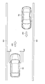
- FIG. 2 shows a bird's-eye view of a scene in which the own vehicle passes through a narrow road as an example of a scene in which the present embodiment is applied.
- roadside objects M1 and M2 such as walls and guardrails and obstacles 60 such as truck vehicles stopped on the road are arranged on the road R.
- the road R has a narrow road between the obstacle 60 and the roadside object M1 through which the own vehicle passes.
- the own vehicle 50 traveling on the road R is traveling in the direction indicated by the arrow v50. Therefore, the own vehicle 50 will later pass by the obstacle 60. That is, the situation shown in FIG. 2 is a situation in which the own vehicle 50 is predicted to pass by the obstacle 60 on a narrow road.
- the vehicle control device 1 of the own vehicle 50 when the own vehicle 50 passes through a narrow road and there is almost no margin between the roadside object M1 and the obstacle 60. Determine if driving assistance is needed. Then, based on the determination result that the driving support is necessary, the control devices 8 to 12 are activated.
- the traveling area three-dimensional information acquisition unit 4 acquires not only the position information on the two-dimensional plane as shown in FIG. 2, but also the three-dimensional position information including the height direction.
- the passability determination unit 6 can determine the passability in consideration of the position in the height direction of the obstacle. it can.
- the heights of the roadside object M1 and the left side mirror are different on the left side of the own vehicle 50, and even if the own vehicle 50 moves to the left. It can be seen that the left side mirror does not interfere with the roadside object M1 and there is a margin that the own vehicle 50 can be moved to the left until the body of the own vehicle 50 comes into contact with the roadside object M1.
- the side surface of the truck of the obstacle 60 faces the right side mirror of the own vehicle 50, and when the own vehicle 50 is moved too far to the right, the tip of the right side mirror faces the obstacle 60. It can be seen that there is a risk of interference. Therefore, the width at which the roadside object M1 and the obstacle 60 may come into contact with each other, that is, from the left end of the body of the own vehicle 50 to the tip of the right side mirror can be acquired as the width w50 of the own vehicle 50.
- step S100 the initial setting of the pass margin area used for the passability determination is performed.
- the initial value of the traffic margin area may be a preset value, or may be manually set by the driver himself, or the driver may refer to the driving history when the vehicle control device 1 has performed control in the past to drive.
- a value may be set according to the driving level of the person.
- the past width adjustment and the driving record on a narrow road may be acquired from the driving history of the driver of the own vehicle, and a margin area may be set according to the driving level of the driver.
- step S101 it is determined whether or not the driver can see the obstacle. Whether or not the driver can see the obstacle is determined at least based on the height information of the obstacle, and more precisely, the height information of the obstacle, the height of the driver's seat of the own vehicle and the height of the window. Judgment is made based on the information and the driver's line-of-sight height information. If it is determined that the obstacle cannot be visually observed, the possibility of contact increases, so the first margin area is added to the initial value of the margin area.
- step S102 it is determined whether or not the obstacle is moving based on the speed information of the obstacle. If it is determined that the obstacle is moving, the possibility of contact increases, so the second margin area is added to the traffic margin area calculated in the above step.
- step S103 it is determined whether or not the own vehicle is traveling at a low speed based on the speed information of the own vehicle. If it is determined that your vehicle is traveling at low speed, it is likely that the driver is driving carefully, judging that there is a possibility of hitting an obstacle, so the traffic calculated in the above step The third traffic margin area is added to the margin area.
- step S104 it is determined whether or not the road surface on which the own vehicle travels has irregularities. If the road surface is uneven, the height of the own vehicle changes depending on the shape of the road surface, so it is necessary to expand the pass margin area. When the road surface on which the own vehicle travels has irregularities, the fourth margin area is added to the traffic margin area calculated in the above step.
- step S105 it is determined whether or not the type of obstacle is a person or a vehicle based on the recognition information of the obstacle. If it is determined that the type of obstacle is a person or a vehicle, there is a higher possibility of contact than a stationary three-dimensional object such as a wall, and damage caused to the human body when contact is made. Is more important and more important than the damage caused to other than the human body, so the fifth margin area is added to the passage margin area calculated in the above step.
- the width in the vehicle width direction is added equally to the left and right with respect to the vehicle center.
- the margin area calculated in steps S100 to S105 is transmitted to the passability determination unit 6.
- the passability determination unit 6 determines whether or not passability is possible based on the information of the width w50 of the own vehicle 50, the width w70 of the pass allowance area in the vehicle width direction calculated by the pass allowance area calculation unit 5, and the passability width w60. judge. Specifically, it is determined that the vehicle can pass when the width obtained by adding the width w50 of the own vehicle 50 and the width w70 in the vehicle width direction of the traffic margin area calculated by the traffic margin area calculation unit 5 is larger than the passable width w60. To do. In that case, even if the passable width w60 is sufficiently wide, it is determined that the pass is possible. Therefore, a threshold value w_th is set so that support does not have to be provided so that unnecessary control is not performed. Passability is determined by the following formula (1). [Number 1] w50 + w70 ⁇ w60 ⁇ w_th ... (1)
- the passable width w60 is smaller than the width w50 of the own vehicle 50 and the width w70 in the vehicle width direction of the margin area calculated by the pass allowance area calculation unit 5, and it is determined that the vehicle cannot pass.
- the width w40 when the side mirror of the own vehicle is stored and the width w70 in the vehicle width direction of the margin area calculated by the passage margin area calculation unit 5 are added, the width is larger than the passable width w60. Is determined. The above is determined by the equation (2). [Number 2] w40 + w70 ⁇ w60 ... (2)
- the passability determination information determined by the above equations (1) and (2) is transmitted to the contact derailment avoidance support unit 7.
- step S200 it is determined whether or not the driver of the own vehicle can see the obstacle from the driver's seat through the window.
- This obstacle also includes gutters below the road surface.
- a known method is used, for example, based on three-dimensional information of a traveling area. Whether or not the driver can see the obstacle is determined at least based on the height information of the obstacle, and more precisely, the height information of the obstacle, the driver's seat height of the own vehicle, and the window. It is geometrically determined based on the height information and the line-of-sight height information of the driver.
- a signal for automatically activating the side camera is transmitted to the side camera 8.
- step S201 it is determined whether or not the obstacle is moving.
- a known method such as an optical flow using an image captured by the front camera 2 is used. Then, when it is determined that the obstacle is moving, at least a signal for changing the distribution of the vehicle left and right in the pass margin area is transmitted to the steering support system 12.
- the change in the allocation of the margin area will be described with reference to FIG.
- FIG. 6 when a moving obstacle 60 exists in the right side region of the own vehicle 50 and a non-moving wall M1 exists in the left side region of the own vehicle 50, driving is performed.
- the person should drive with a margin against the moving obstacle 60, which has a higher risk of contact than the wall M1. Therefore, in the margin areas w1 and w2 that are normally distributed equally to the left and right of the own vehicle 50, the width w1 on the wall M1 side, which is a stationary object, is reduced, and the width on the moving obstacle 60 side. Change the allocation so that w2 is increased.
- step S202 it is determined whether or not the obstacle is a person or a vehicle.
- a known method such as template matching using an image captured by the front camera 2 is used.
- at least a signal for changing the allocation of the margin area is transmitted to the steering support system 12. For example, control is performed to increase the margin area on the side of a person or a vehicle that is an obstacle and reduce the margin area on the side of a stationary object.
- step S203 when the side mirror 10 of the own vehicle 50 is stored, whether or not it is determined that the vehicle is passable by the passable determination unit 6, that is, whether or not it is determined that the vehicle is passable by the above equation (2). It is judged. When it is determined that the vehicle can pass through the above equation (2), at least a signal for automatically storing the side mirror is transmitted to the side mirror 10.
- the vehicle control device 1 determines whether or not the own vehicle can pass on a narrow road based on the information acquired by the front camera 2, and is suitable for the scene faced. Can provide driving assistance.
- the vehicle control device 1 according to the present embodiment when there is an obstacle that may cause contact or derailment due to the own vehicle passing through a narrow road, the vehicle passes based on the contact possibility and the difficulty of passage.
- the margin area is calculated, and the passability judgment is made based on the calculation result.
- a larger margin is provided as compared with the case where the obstacle can be visually recognized, and driving support is provided, so that the driver can drive on a narrow road with peace of mind.
- the present invention is not limited to the above-described embodiments, and various designs are designed without departing from the spirit of the present invention described in the claims. You can make changes.
- the above-described embodiment has been described in detail in order to explain the present invention in an easy-to-understand manner, and is not necessarily limited to the one including all the described configurations.
- it is possible to replace a part of the configuration of one embodiment with the configuration of another embodiment and it is also possible to add the configuration of another embodiment to the configuration of one embodiment.
- Vehicle control device Front camera 3 Own vehicle information 4 Travel area 3D information acquisition unit (3D information acquisition unit) 5 Passage margin area calculation unit 6 Passability judgment unit 7 Contact derailment avoidance support unit (support control unit) 8 Side camera 9 Display 10 Side mirror 11 Speaker 12 Steering support system 50 Own vehicle 60 Obstacles
Landscapes
- Engineering & Computer Science (AREA)
- Mechanical Engineering (AREA)
- Automation & Control Theory (AREA)
- Transportation (AREA)
- Physics & Mathematics (AREA)
- Mathematical Physics (AREA)
- Multimedia (AREA)
- General Physics & Mathematics (AREA)
- Traffic Control Systems (AREA)
- Control Of Driving Devices And Active Controlling Of Vehicle (AREA)
- Rear-View Mirror Devices That Are Mounted On The Exterior Of The Vehicle (AREA)
Priority Applications (2)
| Application Number | Priority Date | Filing Date | Title |
|---|---|---|---|
| CN202080037340.5A CN113874268A (zh) | 2019-05-22 | 2020-05-12 | 车辆控制装置 |
| JP2021520717A JP7230190B2 (ja) | 2019-05-22 | 2020-05-12 | 車両制御装置 |
Applications Claiming Priority (2)
| Application Number | Priority Date | Filing Date | Title |
|---|---|---|---|
| JP2019-096065 | 2019-05-22 | ||
| JP2019096065 | 2019-05-22 |
Publications (1)
| Publication Number | Publication Date |
|---|---|
| WO2020235385A1 true WO2020235385A1 (ja) | 2020-11-26 |
Family
ID=73459250
Family Applications (1)
| Application Number | Title | Priority Date | Filing Date |
|---|---|---|---|
| PCT/JP2020/018907 Ceased WO2020235385A1 (ja) | 2019-05-22 | 2020-05-12 | 車両制御装置 |
Country Status (3)
| Country | Link |
|---|---|
| JP (1) | JP7230190B2 (https=) |
| CN (1) | CN113874268A (https=) |
| WO (1) | WO2020235385A1 (https=) |
Cited By (5)
| Publication number | Priority date | Publication date | Assignee | Title |
|---|---|---|---|---|
| JP2022104791A (ja) * | 2020-12-29 | 2022-07-11 | 三菱電機株式会社 | 経路生成装置及び移動体制御システム |
| JP7158581B1 (ja) * | 2020-12-29 | 2022-10-21 | 三菱電機株式会社 | 経路生成装置、経路生成方法及び経路生成プログラム |
| CN115366918A (zh) * | 2022-08-26 | 2022-11-22 | 上海仙途智能科技有限公司 | 轨迹规划方法及装置、终端设备、计算机可读存储介质 |
| JP2023173692A (ja) * | 2022-05-26 | 2023-12-07 | 日野自動車株式会社 | 制御装置 |
| US20240221383A1 (en) * | 2022-12-28 | 2024-07-04 | Canon Kabushiki Kaisha | Image capturing apparatus and vehicle |
Families Citing this family (1)
| Publication number | Priority date | Publication date | Assignee | Title |
|---|---|---|---|---|
| CN116674540A (zh) * | 2023-07-27 | 2023-09-01 | 苏州鉴智机器人科技有限公司 | 车辆通过控制方法、装置、电子设备及可读存储介质 |
Citations (4)
| Publication number | Priority date | Publication date | Assignee | Title |
|---|---|---|---|---|
| JP2005326963A (ja) * | 2004-05-12 | 2005-11-24 | Fujitsu Ten Ltd | 運転支援装置 |
| JP2009018705A (ja) * | 2007-07-12 | 2009-01-29 | Ichikoh Ind Ltd | 後付用側方視認支援ユニット |
| JP2014069699A (ja) * | 2012-09-28 | 2014-04-21 | Aisin Seiki Co Ltd | 車両用サイドミラー及びその制御方法 |
| JP2019026208A (ja) * | 2017-08-03 | 2019-02-21 | 株式会社Subaru | 車両の運転支援装置 |
Family Cites Families (11)
| Publication number | Priority date | Publication date | Assignee | Title |
|---|---|---|---|---|
| JP3881048B2 (ja) * | 1995-11-06 | 2007-02-14 | 富士重工業株式会社 | 狭路ガイド装置 |
| EP2075170B1 (en) * | 2007-12-28 | 2011-02-16 | Magneti Marelli S.p.A. | A driving assistance system for a vehicle travelling along a roadway that lacks lane demarcation lines |
| JP2010070061A (ja) * | 2008-09-18 | 2010-04-02 | Toyota Motor Corp | 車両走行支援装置 |
| JP5248451B2 (ja) * | 2009-09-04 | 2013-07-31 | 本田技研工業株式会社 | 車両用接触回避支援装置 |
| US9669826B2 (en) * | 2012-11-21 | 2017-06-06 | Toyota Jidosha Kabushiki Kaisha | Driving-assistance device and driving-assistance method |
| US10421398B2 (en) * | 2012-11-21 | 2019-09-24 | Toyota Jidosha Kabushiki Kaisha | Driving-assistance device and driving-assistance method |
| KR102270578B1 (ko) * | 2014-11-18 | 2021-06-29 | 현대모비스 주식회사 | 차량의 전방 정보 표시 제어 장치 및 방법 |
| JP6222137B2 (ja) * | 2015-03-02 | 2017-11-01 | トヨタ自動車株式会社 | 車両制御装置 |
| JP6432447B2 (ja) * | 2015-05-27 | 2018-12-05 | 株式会社デンソー | 車両制御装置、及び車両制御方法 |
| JP6530705B2 (ja) * | 2015-12-25 | 2019-06-12 | 株式会社デンソー | 運転支援装置及び運転支援方法 |
| JP6382887B2 (ja) * | 2016-06-03 | 2018-08-29 | 本田技研工業株式会社 | 走行制御装置 |
-
2020
- 2020-05-12 CN CN202080037340.5A patent/CN113874268A/zh active Pending
- 2020-05-12 WO PCT/JP2020/018907 patent/WO2020235385A1/ja not_active Ceased
- 2020-05-12 JP JP2021520717A patent/JP7230190B2/ja active Active
Patent Citations (4)
| Publication number | Priority date | Publication date | Assignee | Title |
|---|---|---|---|---|
| JP2005326963A (ja) * | 2004-05-12 | 2005-11-24 | Fujitsu Ten Ltd | 運転支援装置 |
| JP2009018705A (ja) * | 2007-07-12 | 2009-01-29 | Ichikoh Ind Ltd | 後付用側方視認支援ユニット |
| JP2014069699A (ja) * | 2012-09-28 | 2014-04-21 | Aisin Seiki Co Ltd | 車両用サイドミラー及びその制御方法 |
| JP2019026208A (ja) * | 2017-08-03 | 2019-02-21 | 株式会社Subaru | 車両の運転支援装置 |
Cited By (7)
| Publication number | Priority date | Publication date | Assignee | Title |
|---|---|---|---|---|
| JP2022104791A (ja) * | 2020-12-29 | 2022-07-11 | 三菱電機株式会社 | 経路生成装置及び移動体制御システム |
| JP7158581B1 (ja) * | 2020-12-29 | 2022-10-21 | 三菱電機株式会社 | 経路生成装置、経路生成方法及び経路生成プログラム |
| JP7270017B2 (ja) | 2020-12-29 | 2023-05-09 | 三菱電機株式会社 | 経路生成装置及び移動体制御システム |
| JP2023173692A (ja) * | 2022-05-26 | 2023-12-07 | 日野自動車株式会社 | 制御装置 |
| CN115366918A (zh) * | 2022-08-26 | 2022-11-22 | 上海仙途智能科技有限公司 | 轨迹规划方法及装置、终端设备、计算机可读存储介质 |
| US20240221383A1 (en) * | 2022-12-28 | 2024-07-04 | Canon Kabushiki Kaisha | Image capturing apparatus and vehicle |
| US12423986B2 (en) * | 2022-12-28 | 2025-09-23 | Canon Kabushiki Kaisha | Image capturing apparatus and vehicle |
Also Published As
| Publication number | Publication date |
|---|---|
| JPWO2020235385A1 (https=) | 2020-11-26 |
| JP7230190B2 (ja) | 2023-02-28 |
| CN113874268A (zh) | 2021-12-31 |
Similar Documents
| Publication | Publication Date | Title |
|---|---|---|
| WO2020235385A1 (ja) | 車両制御装置 | |
| US12179796B2 (en) | Autonomous control system that performs pull-over operations through sequential steering and deceleration inputs | |
| RU2767216C1 (ru) | Способ управления движением транспортного средства и аппаратура управления движением транспортного средства | |
| JP7128623B2 (ja) | 車両の予見的制御 | |
| CN101460353B (zh) | 行驶辅助装置 | |
| JP5300357B2 (ja) | 衝突防止支援装置 | |
| JP5070171B2 (ja) | 車両制御装置 | |
| US12243417B2 (en) | Control system and control method for path assignment of traffic objects | |
| CN110799401B (zh) | 车辆控制装置 | |
| JP2017114405A (ja) | 運転支援装置 | |
| JP2017037473A (ja) | 操舵支援装置 | |
| JP7178297B2 (ja) | 運転支援装置 | |
| WO2017065297A1 (ja) | 表示制御装置および車両制御装置 | |
| KR20120035122A (ko) | 차량의 주차 과정 실행 방법 및 차량의 주차 과정 제어 장치 | |
| KR102591992B1 (ko) | 차량 및 그 제어방법 | |
| JP2016030537A (ja) | 車両用走行支援装置 | |
| CN111565981B (zh) | 车辆控制装置 | |
| JP2018156290A (ja) | 衝突回避装置 | |
| JP2016049953A (ja) | 後方確認装置及び後方確認方法 | |
| KR20160134105A (ko) | 차선 유지 제어 장치 및 방법 | |
| JP7269846B2 (ja) | 車両運転支援方法及び車両運転支援システム | |
| US20180286241A1 (en) | Method and system for a motor vehicle | |
| JP7698495B2 (ja) | 駐車支援装置 | |
| CN116691666A (zh) | 一种基于补盲激光雷达的窄路掉头方法与系统 | |
| JP7279307B2 (ja) | 車両制御装置および車両制御方法 |
Legal Events
| Date | Code | Title | Description |
|---|---|---|---|
| 121 | Ep: the epo has been informed by wipo that ep was designated in this application |
Ref document number: 20809332 Country of ref document: EP Kind code of ref document: A1 |
|
| ENP | Entry into the national phase |
Ref document number: 2021520717 Country of ref document: JP Kind code of ref document: A |
|
| NENP | Non-entry into the national phase |
Ref country code: DE |
|
| 122 | Ep: pct application non-entry in european phase |
Ref document number: 20809332 Country of ref document: EP Kind code of ref document: A1 |