WO2020217799A1 - Système de climatisation - Google Patents
Système de climatisation Download PDFInfo
- Publication number
- WO2020217799A1 WO2020217799A1 PCT/JP2020/012271 JP2020012271W WO2020217799A1 WO 2020217799 A1 WO2020217799 A1 WO 2020217799A1 JP 2020012271 W JP2020012271 W JP 2020012271W WO 2020217799 A1 WO2020217799 A1 WO 2020217799A1
- Authority
- WO
- WIPO (PCT)
- Prior art keywords
- temperature
- indoor
- air
- conditioning system
- target temperature
- Prior art date
Links
Images


Classifications
-
- F—MECHANICAL ENGINEERING; LIGHTING; HEATING; WEAPONS; BLASTING
- F24—HEATING; RANGES; VENTILATING
- F24F—AIR-CONDITIONING; AIR-HUMIDIFICATION; VENTILATION; USE OF AIR CURRENTS FOR SCREENING
- F24F11/00—Control or safety arrangements
- F24F11/62—Control or safety arrangements characterised by the type of control or by internal processing, e.g. using fuzzy logic, adaptive control or estimation of values
- F24F11/63—Electronic processing
- F24F11/65—Electronic processing for selecting an operating mode
- F24F11/67—Switching between heating and cooling modes
-
- F—MECHANICAL ENGINEERING; LIGHTING; HEATING; WEAPONS; BLASTING
- F24—HEATING; RANGES; VENTILATING
- F24F—AIR-CONDITIONING; AIR-HUMIDIFICATION; VENTILATION; USE OF AIR CURRENTS FOR SCREENING
- F24F11/00—Control or safety arrangements
- F24F11/70—Control systems characterised by their outputs; Constructional details thereof
- F24F11/80—Control systems characterised by their outputs; Constructional details thereof for controlling the temperature of the supplied air
-
- F—MECHANICAL ENGINEERING; LIGHTING; HEATING; WEAPONS; BLASTING
- F24—HEATING; RANGES; VENTILATING
- F24F—AIR-CONDITIONING; AIR-HUMIDIFICATION; VENTILATION; USE OF AIR CURRENTS FOR SCREENING
- F24F11/00—Control or safety arrangements
- F24F11/62—Control or safety arrangements characterised by the type of control or by internal processing, e.g. using fuzzy logic, adaptive control or estimation of values
- F24F11/63—Electronic processing
- F24F11/65—Electronic processing for selecting an operating mode
-
- F—MECHANICAL ENGINEERING; LIGHTING; HEATING; WEAPONS; BLASTING
- F24—HEATING; RANGES; VENTILATING
- F24F—AIR-CONDITIONING; AIR-HUMIDIFICATION; VENTILATION; USE OF AIR CURRENTS FOR SCREENING
- F24F11/00—Control or safety arrangements
- F24F11/70—Control systems characterised by their outputs; Constructional details thereof
- F24F11/80—Control systems characterised by their outputs; Constructional details thereof for controlling the temperature of the supplied air
- F24F11/81—Control systems characterised by their outputs; Constructional details thereof for controlling the temperature of the supplied air by controlling the air supply to heat-exchangers or bypass channels
-
- F—MECHANICAL ENGINEERING; LIGHTING; HEATING; WEAPONS; BLASTING
- F24—HEATING; RANGES; VENTILATING
- F24F—AIR-CONDITIONING; AIR-HUMIDIFICATION; VENTILATION; USE OF AIR CURRENTS FOR SCREENING
- F24F11/00—Control or safety arrangements
- F24F11/70—Control systems characterised by their outputs; Constructional details thereof
- F24F11/80—Control systems characterised by their outputs; Constructional details thereof for controlling the temperature of the supplied air
- F24F11/86—Control systems characterised by their outputs; Constructional details thereof for controlling the temperature of the supplied air by controlling compressors within refrigeration or heat pump circuits
-
- G—PHYSICS
- G05—CONTROLLING; REGULATING
- G05D—SYSTEMS FOR CONTROLLING OR REGULATING NON-ELECTRIC VARIABLES
- G05D23/00—Control of temperature
- G05D23/19—Control of temperature characterised by the use of electric means
- G05D23/1919—Control of temperature characterised by the use of electric means characterised by the type of controller
-
- F—MECHANICAL ENGINEERING; LIGHTING; HEATING; WEAPONS; BLASTING
- F24—HEATING; RANGES; VENTILATING
- F24F—AIR-CONDITIONING; AIR-HUMIDIFICATION; VENTILATION; USE OF AIR CURRENTS FOR SCREENING
- F24F2110/00—Control inputs relating to air properties
- F24F2110/10—Temperature
-
- F—MECHANICAL ENGINEERING; LIGHTING; HEATING; WEAPONS; BLASTING
- F24—HEATING; RANGES; VENTILATING
- F24F—AIR-CONDITIONING; AIR-HUMIDIFICATION; VENTILATION; USE OF AIR CURRENTS FOR SCREENING
- F24F2110/00—Control inputs relating to air properties
- F24F2110/10—Temperature
- F24F2110/12—Temperature of the outside air
-
- F—MECHANICAL ENGINEERING; LIGHTING; HEATING; WEAPONS; BLASTING
- F24—HEATING; RANGES; VENTILATING
- F24F—AIR-CONDITIONING; AIR-HUMIDIFICATION; VENTILATION; USE OF AIR CURRENTS FOR SCREENING
- F24F2110/00—Control inputs relating to air properties
- F24F2110/20—Humidity
-
- F—MECHANICAL ENGINEERING; LIGHTING; HEATING; WEAPONS; BLASTING
- F24—HEATING; RANGES; VENTILATING
- F24F—AIR-CONDITIONING; AIR-HUMIDIFICATION; VENTILATION; USE OF AIR CURRENTS FOR SCREENING
- F24F2110/00—Control inputs relating to air properties
- F24F2110/20—Humidity
- F24F2110/22—Humidity of the outside air
-
- F—MECHANICAL ENGINEERING; LIGHTING; HEATING; WEAPONS; BLASTING
- F24—HEATING; RANGES; VENTILATING
- F24F—AIR-CONDITIONING; AIR-HUMIDIFICATION; VENTILATION; USE OF AIR CURRENTS FOR SCREENING
- F24F2110/00—Control inputs relating to air properties
- F24F2110/50—Air quality properties
- F24F2110/65—Concentration of specific substances or contaminants
- F24F2110/70—Carbon dioxide
-
- F—MECHANICAL ENGINEERING; LIGHTING; HEATING; WEAPONS; BLASTING
- F24—HEATING; RANGES; VENTILATING
- F24F—AIR-CONDITIONING; AIR-HUMIDIFICATION; VENTILATION; USE OF AIR CURRENTS FOR SCREENING
- F24F2130/00—Control inputs relating to environmental factors not covered by group F24F2110/00
- F24F2130/30—Artificial light
-
- Y—GENERAL TAGGING OF NEW TECHNOLOGICAL DEVELOPMENTS; GENERAL TAGGING OF CROSS-SECTIONAL TECHNOLOGIES SPANNING OVER SEVERAL SECTIONS OF THE IPC; TECHNICAL SUBJECTS COVERED BY FORMER USPC CROSS-REFERENCE ART COLLECTIONS [XRACs] AND DIGESTS
- Y02—TECHNOLOGIES OR APPLICATIONS FOR MITIGATION OR ADAPTATION AGAINST CLIMATE CHANGE
- Y02B—CLIMATE CHANGE MITIGATION TECHNOLOGIES RELATED TO BUILDINGS, e.g. HOUSING, HOUSE APPLIANCES OR RELATED END-USER APPLICATIONS
- Y02B30/00—Energy efficient heating, ventilation or air conditioning [HVAC]
- Y02B30/70—Efficient control or regulation technologies, e.g. for control of refrigerant flow, motor or heating
Definitions
- This disclosure relates to an air conditioning system.
- the purpose of the present disclosure is to both prevent the occupants from feeling drowsy and to realize a comfortable indoor environment.
- the first aspect of the present disclosure is detected by a temperature control unit (37) that regulates the temperature of the room air, an inside air temperature detection unit (45) that detects the temperature of the room air, and an inside air temperature detection unit (45).
- the target is an air conditioning system (1) equipped with a control unit (11) that controls a temperature control unit (37) so that the temperature approaches the target temperature.
- the control unit (11) sequentially performs at least one first operation of lowering the target temperature to a first target temperature lower than a predetermined reference temperature and a second operation of raising the target temperature to a second target temperature higher than the reference temperature.
- the first mode which is performed once, is executed.
- the target temperature is gradually raised from the first target temperature to the second target temperature.
- the time required to lower the target temperature to the first target temperature in the first operation is shorter than the time required to raise the target temperature to the second target temperature in the second operation.
- the target temperature is lowered to the first target temperature in a relatively short time in the first operation.
- the temperature of the indoor air is quickly lowered and becomes lower than the reference temperature. Therefore, the indoor temperature is set to a temperature at which the occupant (101) feels cool, and the occupant (101) is stimulated to cool. Is given. As a result, it is possible to prevent the occupant (101) from feeling drowsy.
- the target temperature is gradually raised to the second target temperature over a relatively long time.
- the temperature of the indoor air is gradually raised to be higher than the reference temperature, so that the period during which the first operation is performed and the second operation while reducing the burden on the occupant (101) due to the temperature change.
- the average temperature of the indoor air during the total period of the operation can be set to a comfortable temperature for the occupant (101). As a result, a comfortable indoor environment can be realized for the occupant (101).
- the temperature control unit (37) is configured by an indoor heat exchanger (37) connected to a refrigerant circuit (17). , Air conditioning system (1).
- the control unit (11) executes the first mode during the cooling operation in which the indoor heat exchanger (37) functions as an evaporator. Then, the control unit (11) stops the indoor heat exchanger (37) when the temperature detected by the inside air temperature detection unit (45) becomes lower than the target temperature by a predetermined temperature or more.
- the indoor heat exchanger (37) is stopped when the temperature detected by the inside air temperature detection unit (45) becomes lower than the target temperature by a predetermined temperature or more during the cooling operation. Therefore, during the cooling operation, if the target temperature is set higher than the temperature detected by the inside air temperature detection unit (45) by a predetermined temperature or higher, the indoor heat exchanger (37) is stopped, but the indoor fan (39) is stopped. ) Can be in a driving state. In that case, the moisture adhering to the indoor heat exchanger (37) is released into the room by blowing air, so that the humidity of the indoor air rises, which causes discomfort to the occupant (101).
- the target temperature is gradually raised from the first target temperature to the second target temperature, so that it is detected by the inside air temperature detection unit (45) during the cooling operation. It is difficult for the temperature to be set to be lower than the target temperature by a predetermined temperature or higher, and it is possible to prevent the indoor heat exchanger (37) from being stopped. As a result, it is possible to prevent the occupant (101) from being uncomfortable due to the increase in the humidity of the indoor air.
- the temperature control unit (37) is configured by an indoor heat exchanger (37) connected to a refrigerant circuit (17). , Air conditioning system (1).
- the control unit (11) executes the first mode during the heating operation in which the indoor heat exchanger (37) functions as a heat dissipation unit. Then, the control unit (11) stops the indoor heat exchanger (37) when the temperature detected by the inside air temperature detection unit (45) becomes higher than the target temperature by a predetermined temperature or more.
- the indoor heat exchanger (37) is stopped when the temperature detected by the inside air temperature detection unit (45) becomes higher than the target temperature by a predetermined temperature or more during the heating operation.
- the first target temperature is likely to be set lower than the temperature detected by the inside air temperature detection unit (45) by a predetermined temperature or more. This contributes to stopping the indoor heat exchanger (37) shortly after starting the first operation and rapidly lowering the temperature of the indoor air.
- a fourth aspect of the present disclosure is the comfortable temperature of the indoor air that the control unit (11) feels comfortable to the occupant (101) in the air conditioning system (1) of any one of the first to third aspects.
- the reference temperature is a comfortable temperature estimated by the control unit (11).
- the comfortable temperature estimated by the control unit (11) is used as the reference temperature. According to this, it is easy for the occupant (101) to set the average temperature of the indoor air in the total period of the period in which the first operation is performed and the period in which the second operation is performed to be a comfortable temperature. Therefore, it is suitable to realize a comfortable indoor environment for the occupant (101) by controlling the temperature of the indoor air in the first mode.
- the control unit (11) determines the temperature of the indoor air, the humidity of the indoor air, the illuminance of the room, the temperature of the outside air, and the humidity of the outside air. It is an air conditioning system (1) that estimates a comfortable temperature by a learning model generated based on a parameter related to environmental information including at least one and a parameter related to the feeling of warmth and coldness of a resident (101).
- the comfortable temperature used as the reference temperature is estimated by a learning model that associates the environmental information with the warm / cold feeling of the occupant (101).
- the temperature of the indoor air that the occupant (101) feels comfortable can be accurately estimated as the comfortable temperature and set as the reference temperature. This is advantageous for realizing a comfortable indoor environment for the occupant (101) by controlling the temperature of the indoor air in the first mode.
- the outside air temperature detecting unit (53) for detecting the outside air temperature and the relational information indicating the relationship between the comfortable temperature and the outside air temperature are stored. It is an air conditioning system (1) equipped with a storage unit (59).
- the control unit (11) estimates the comfortable temperature based on the outside air temperature detected by the outside air temperature detection unit (53) using the relational information stored in the storage unit (59).
- the comfortable temperature used as the reference temperature is estimated from the outside air temperature detected by the outside air temperature detecting unit (53) using the relational information indicating the relationship between the comfortable temperature and the outside air temperature.
- the general comfortable temperature can be estimated as the temperature of the indoor air that the occupant (101) feels comfortable, and can be set as the reference temperature. This is advantageous for realizing a comfortable indoor environment for the occupant (101) by controlling the temperature of the indoor air in the first mode.
- a seventh aspect of the present disclosure includes an input unit (9) in which information regarding individual differences of occupants (101) is input in the air conditioning system (1) of any one of the fourth to sixth aspects. , Air conditioning system (1).
- the control unit (11) corrects the reference temperature based on the information input to the input unit (9).
- control unit (11) corrects the reference temperature based on the information regarding the individual differences of the occupants (101). As a result, information on individual differences of the occupants (101) is reflected in the reference temperature, so that the temperature of the indoor air that the occupants (101) feel comfortable with can be used accurately as the reference temperature. This is advantageous for realizing a comfortable indoor environment for the occupant (101) by controlling the temperature of the indoor air in the first mode.
- An eighth aspect of the present disclosure is an air conditioning system (1) including an indoor unit (5) having a temperature control unit (37) in any one of the air conditioning systems (1) of the first to seventh aspects. is there.
- the inside air temperature detection unit (45) is provided as a separate component from the indoor unit (5).
- the inside air temperature detection unit (45) is provided as a separate component from the indoor unit (5). Another part provided with the inside air temperature detection unit (45) can be arranged near the occupant (101). Therefore, the temperature of the indoor air in the vicinity of the occupant (101) can be detected by the inside air temperature detecting unit (45). This is suitable for realizing a comfortable indoor environment for the occupant (101) by controlling the temperature of the indoor air in the first mode.
- a ninth aspect of the present disclosure is a period during which the first operation is performed in any one of the first to eighth aspects of the air conditioning system (1), when the reference temperature is Ta and the target temperature is Ts.
- the integrated value of the temperature difference (Ta-Ts) between the reference temperature and the target temperature is equal to the integrated value of the temperature difference (Ts-Ta) between the target temperature and the reference temperature during the second operation.
- Air conditioning system (1) Air conditioning system (1).
- the target temperature and execution time of the first operation and the target temperature and execution time of the second operation are the sum of one period during which the first operation is performed and one period during which the second operation is performed.
- the average temperature of the room air during the period is determined to be the reference temperature. This is suitable for realizing a comfortable indoor environment for the occupant (101) by controlling the temperature of the indoor air in the first mode.
- a tenth aspect of the present disclosure is a ventilation device (7) for ventilating indoor air and carbon dioxide for detecting the carbon dioxide concentration in the room in the air conditioning system (1) of any one of the first to ninth aspects. It is an air conditioning system (1) equipped with a concentration detection unit (49). The control unit (11) operates the ventilation device (7) when the carbon dioxide concentration detected by the carbon dioxide concentration detection unit (49) exceeds a predetermined value.
- the ventilation device (7) is operated when the carbon dioxide concentration in the room detected by the carbon dioxide concentration detection unit (49) exceeds a predetermined value. High levels of carbon dioxide in the room can lead to increased fatigue, fatigue, and drowsiness.
- the ventilation device (7) is operated, the indoor air is replaced and the carbon dioxide concentration in the room is lowered, which is suitable for realizing a comfortable indoor environment for the occupant (101).
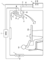
- FIG. 1 is a schematic view schematically showing an air conditioning system of an embodiment.
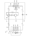
- FIG. 2 is a diagram showing a refrigerant circuit constituting the air conditioning system of the embodiment.
- FIG. 3 is a block diagram showing the configuration of the air conditioning system of the embodiment.
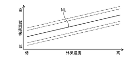
- FIG. 4 is an image diagram of related information (adaptive model of thermal comfort) used in the air conditioning system of the embodiment.
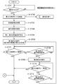
- FIG. 5 is a flowchart of the concentration maintaining mode during the cooling operation in the air conditioning system of the embodiment.
- FIG. 6 is a flowchart of the concentration maintaining mode during the heating operation in the air conditioning system of the embodiment.
- FIG. 7 is a flowchart of ventilation control in the concentration maintenance mode in the air conditioning system of the embodiment.
- Embodiment 1 The first embodiment will be described.
- the air-conditioning system (1) of the first embodiment is a system that contributes to maintaining the concentration of the occupants (101) on the work, and the occupants (101) such as an office or a study room perform the work. It is used to perform air conditioning for the room.
- the air conditioning system (1) includes an outdoor unit (3) installed outdoors, an indoor unit (5) and a ventilation device (7) installed indoors, and a remote controller (9). , Various sensors (45,47,49,51,53,55) and a control unit (11) that comprehensively controls the operation of the air conditioning system (1) are provided.
- the outdoor unit (3) and the indoor unit (5) are connected by connecting pipes (13, 15) to form a refrigerant circuit (17) shown in FIG.
- a vapor compression refrigeration cycle is performed by circulating the filled refrigerant.
- the refrigerant for example, R32 refrigerant is used.
- the refrigerant circuit (17) includes an outdoor circuit (19) and an indoor circuit (21).
- the outdoor unit (3) is installed outdoors, for example, on the roof of a building, on the ground beside a building, or on a balcony.
- the outdoor unit (3) has a compressor (23), a four-way switching valve (25), an outdoor heat exchanger (27), an expansion valve (29), and an outdoor fan (31).
- the compressor (23), the four-way switching valve (25), the outdoor heat exchanger (27), and the expansion valve (29) are connected in this order by the refrigerant pipe (33) to form the outdoor circuit (19).
- the compressor (23) compresses the sucked refrigerant and discharges the compressed refrigerant.
- the compressor (23) is configured as an inverter type having a variable capacity, for example.
- the compressor (23) is, for example, a rotary compressor.
- the outdoor fan (31) is installed near the outdoor heat exchanger (27).
- the outdoor fan (31) is driven by an outdoor fan motor (35).
- the outdoor fan (31) is composed of, for example, a propeller fan.
- the outdoor fan (31) conveys the outside air and passes it through the outdoor heat exchanger (27).
- the outdoor heat exchanger (27) exchanges heat between the outside air conveyed by the outdoor fan (31) and the refrigerant flowing inside.
- the outdoor heat exchanger (27) is composed of, for example, a fin-and-tube heat exchanger.
- the expansion valve (29) is a control valve having a variable opening degree.
- the expansion valve (29) depressurizes the refrigerant flowing inside.
- the expansion valve (29) is composed of, for example, an electronic expansion valve.
- the four-way switching valve (25) switches the flow path of the refrigerant in the refrigerant circuit (17) between the first state (the state shown by the solid line in FIG. 2) and the second state (the state shown by the broken line in FIG. 2).
- the four-way switching valve (25) in the first state communicates the discharge part of the compressor (23) with the outdoor heat exchanger (27), and connects the suction part of the compressor (23) with the indoor heat exchanger (37).
- the four-way switching valve (25) in the second state communicates the discharge part of the compressor (23) with the indoor heat exchanger (37), and connects the suction part of the compressor (23) with the outdoor heat exchanger (27). To communicate.
- the indoor unit (5) is attached to the wall or ceiling of the room, for example.
- the indoor unit (5) shown in FIG. 1 is a wall-mounted unit mounted on a wall surface.
- the indoor unit (5) has an indoor heat exchanger (37) and an indoor fan (39).
- the indoor heat exchanger (37) constitutes the indoor circuit (21).
- the indoor fan (39) is installed near the indoor heat exchanger (37).
- the indoor fan (39) is driven by the indoor fan motor (41).
- the indoor fan (39) is composed of, for example, a cross flow fan.
- the indoor fan (39) conveys the indoor air and passes it through the indoor heat exchanger (37).
- the indoor heat exchanger (37) exchanges heat between the indoor air conveyed by the indoor fan (39) and the refrigerant flowing inside.
- the indoor heat exchanger (37) is composed of, for example, a fin-and-tube heat exchanger.
- the indoor heat exchanger (37) is an example of a temperature control unit that regulates the temperature of the indoor air.
- the outdoor heat exchanger (27) functions as a condenser and the indoor heat exchanger (37) functions as a radiator (evaporator).
- a refrigeration cycle (a refrigeration cycle in which the refrigerant flows in the direction of the solid arrow in FIG. 2) is performed.
- the outdoor heat exchanger (27) functions as a radiator (evaporator) and the indoor heat exchanger (37) is a condenser.
- a refrigeration cycle (a refrigeration cycle in which the refrigerant flows in the direction of the broken arrow in FIG. 2) is performed.
- the ventilation device (7) is attached to the wall surface or ceiling of the room, for example.
- the ventilation device (7) shown in FIG. 1 is a wall-mounted device mounted on a wall surface.
- the ventilation device (7) has a ventilation fan (43) and, if necessary, a duct.
- the ventilation fan (43) takes in the outside air into the room and discharges the room air to the outside.
- the ventilation fan (43) is driven by a ventilation fan motor (not shown).
- the remote controller (9) is a separate part from the indoor unit (5) and may be placed near the occupant (101), such as on the desk (103) where the occupant (101) works. There are many.
- the remote controller (9) is configured to be operable by a resident (101). Although not shown, the remote controller (9) has an operation unit operated by the occupant (101) and a display unit for displaying predetermined information.
- the remote controller (9) is wirelessly connected to the control unit (11).
- the remote controller (9) outputs an operation signal to the control unit (9).
- the air conditioning system (1) can be turned on and off, the operation mode and control mode can be switched, the arousal strength can be set in the concentration maintenance mode described later, and the correction information regarding the reference temperature described later can be input.
- the operation unit has a plurality of buttons for performing these various operations.
- the plurality of buttons include a concentration button for turning on and off the concentration maintenance mode described later, and a selection button for setting the arousal strength.
- the "awakening strength” indicates the degree of the strength of the cool stimulus to the occupant (101) in the concentration maintenance mode. The details of the arousal strength setting will be described later.
- the correction information input by the operation unit is information related to individual differences of the occupants (101).
- the correction information may be information on the heat and cold experience of the occupant (101) (abstract information such as hot or cold). Further, the correction information may be information on a specific correction temperature such as + 1.0 ° C. or ⁇ 1.0 ° C. In addition, the correction information may be individual parameters related to the feeling of warmth and coldness such as gender, age, metabolic rate, body fat percentage, and blood pressure of the occupant (101).
- the set temperature (reference temperature), indoor air humidity, operation mode information, etc. are displayed on the display unit.
- the operation mode information includes whether the operation is cooling operation or heating operation, whether the concentration maintenance mode described later is being executed, and which of the awakening strengths is set in the concentration maintenance mode. Can be mentioned.
- the sensors include an inside air temperature sensor (45), an inside air humidity sensor (47), a CO 2 concentration sensor (49), an illuminance sensor (51), an outside air temperature sensor (53), and an outside air humidity sensor (55).
- Each of these sensors (45,47,49,51,53,55) is connected to the control unit (11) by wire or wirelessly.
- Each sensor (45,47,49,51,53,55) outputs a detection signal to the control unit (11).
- the indoor temperature sensor (47) is an example of the inside air temperature detection unit.
- the CO 2 concentration sensor (49) is an example of a carbon dioxide concentration detection unit.
- the inside air temperature sensor (45), the inside air humidity sensor (47), the CO 2 concentration sensor (49), and the illuminance sensor (51) are provided in, for example, the indoor unit (5).
- the indoor temperature sensor (45) detects the temperature of the indoor air sucked into the indoor unit (5).
- the indoor humidity sensor (47) detects the humidity of the indoor air sucked into the indoor unit (5).
- the CO 2 concentration sensor (49) detects the CO 2 concentration (carbon dioxide concentration) of the indoor air sucked into the indoor unit (5).
- the illuminance sensor (51) detects the brightness (illuminance) in the room.
- the outside air temperature sensor (53) and the outside air humidity sensor (55) are provided in, for example, the outdoor unit (3).
- the outside air temperature sensor (53) detects the temperature of the outside air sucked into the outdoor unit (3).
- the outside air humidity sensor (55) detects the humidity of the outside air sucked into the outdoor unit (3).
- the control unit (11) is a controller based on a well-known microcomputer. As shown in FIG. 3, the control unit (11) stores a central processing unit (CPU) (57) that executes a program and various programs and data executed on the central processing unit. It has a storage unit (59).
- the storage unit (59) is composed of a ROM (Read Only Memory), a RAM (Random Access Memory), and the like.
- the control unit (11) is built in, for example, the indoor unit (5).
- the control unit (11) detects the inside air temperature sensor (45), the inside air humidity sensor (47), the CO 2 concentration sensor (49), the illuminance sensor (51), the outside air temperature sensor (53), and the outside air humidity sensor (55). Based on the signal and the operation signal from the remote controller (9), the outdoor unit (3) (compressor (23), four-way switching valve (25), expansion valve (29), outdoor fan (31)), indoor unit ( 5) Calculate the control amount of (indoor fan (39)) and ventilation device (7) (ventilation fan (43)). The control unit (11) outputs a control signal related to the calculated control amount to the outdoor unit (3), the indoor unit (5), and the ventilation device (7).
- the storage unit (59) contains at least one of the humidity of the room air, the CO 2 concentration of the room air, the illuminance of the room, the outside air temperature and the outside air humidity, and the comfortable temperature of the room air that the occupant (101) feels comfortable with. Relationship information indicating the relationship with is stored.
- the relationship information for example, information on an adaptive model of thermal comfort known as an adaptive comfort model is used.
- the comfortable temperature of the occupant (101) fluctuates according to the outside air temperature depending on the ability of the person to adapt to the environment.
- the adaptive model of thermal comfort is a model obtained by regression analysis from statistical information based on the declaration of the temperature of the indoor air and the feeling of warmth and coldness of the occupant (101), and is represented by the graph of FIG. This is information showing the relationship between the outside air temperature and the comfortable temperature.
- the comfort temperature increases as the outside air temperature increases.
- the range between the upper and lower dash-dotted lines indicates the range of comfortable temperatures that 90% of humans feel comfortable statistically
- the range between the upper and lower dash-dotted lines is statistically comfortable for 80% of humans. It shows the range of comfortable temperature that you feel.
- the control unit (11) uses the relationship information stored in the storage unit (59), and in the first embodiment, the information of the adaptive model of thermal comfort, and is based on the outside air temperature detected by the outside air temperature sensor (53).
- the comfortable temperature of the occupant (101) is estimated.
- the concept of neutral temperature which is a temperature that human beings feel comfortable without being hot or cold, is known.
- the intermediate temperature shown by the solid line NL in the comfortable temperature range can be regarded as the neutral temperature.
- the control unit (11) estimates the neutral temperature obtained from the outside air temperature by this adaptive model of thermal comfort as the comfort temperature of the occupant (101).
- the control unit (11) automatically sets the reference temperature based on the estimated comfort temperature.
- the control unit (11) sets the estimated comfort temperature as the reference temperature when the correction information regarding the reference temperature is not input by the remote controller (9).
- the control unit (11) corrects the reference temperature based on the correction information.
- the reference temperature is corrected by a predetermined temperature, and the information that the occupant (101) is cold is input. If so, the correction is performed to raise the reference temperature by a predetermined temperature. Further, when specific correction temperature information is input as the correction information, the correction is performed to raise or lower the reference temperature according to the correction temperature. Further, when an individual parameter related to the feeling of warmth and coldness is input as the correction information, the correction is performed to raise or lower the reference temperature by a predetermined temperature determined according to the individual parameter.
- control unit (11) may be able to set the reference temperature based on the operation signal from the remote controller (9).
- the reference temperature may be manually set by the occupant operating the remote controller (9).
- the control unit (11) controls the operation of the outdoor unit (3) and the indoor unit (5) in the specified operation mode (cooling operation or heating operation) based on the operation signal from the remote controller (9).
- the operation of the air conditioning system (1) is controlled based on the detection signals from the various sensors (45,47,49,51,53,55) described above.
- the control unit (11) has a plurality of control modes, and is an outdoor unit (3), an indoor unit (5), and a ventilation device (7) according to the control mode set by the operation signal from the remote controller (9). Control the operation of.
- the control unit (11) has, as a control mode, a concentration maintenance mode for increasing the concentration of the occupant (101) and a normal operation mode for transitioning when the concentration maintenance mode is off.
- concentration maintenance mode is an example of the first mode.
- control unit (11) controls the operation of the ventilation device (7) based on the CO 2 concentration of the indoor air detected by the CO 2 sensor.
- the CO 2 concentration is one of the indexes for evaluating the indoor air quality. A high CO 2 concentration in the room air can lead to increased fatigue, fatigue, and drowsiness. Therefore, it is desirable that the CO 2 concentration in the indoor air does not become too high.
- the control unit (11) operates the ventilation device (7) when the CO 2 concentration in the room detected by the CO 2 concentration sensor (49) becomes equal to or higher than a predetermined first reference value.
- the first reference value is set to, for example, 1000 ppm according to a guideline set for environmental management of buildings.
- the control unit (11) stops the ventilation device (7) when the CO 2 concentration of the indoor air detected by the CO 2 concentration sensor (49) becomes less than a predetermined second reference value.
- the second reference value is set to, for example, 900 ppm.
- the air conditioning system (1) switches between cooling operation and heating operation according to the operation mode set by the remote controller (9) to adjust the temperature of the indoor air.
- the concentration maintenance mode can be executed by pressing the concentration button on the remote controller (9) and released by re-operating the concentration button in both the cooling operation and the heating operation.
- the four-way switching valve (25) is set to the first state.
- the refrigerant compressed by the compressor (23) is radiated (condensed) by the outdoor heat exchanger (27) that functions as a radiator.
- the radiated refrigerant is depressurized by the expansion valve (29) and then flows through the indoor heat exchanger (37) that functions as an evaporator.
- the indoor heat exchanger (37) the refrigerant absorbs heat from the indoor air and evaporates.
- the indoor air cooled by the indoor heat exchanger (37) is blown into the indoor space by the indoor fan (39).
- the evaporated refrigerant is sucked into the compressor (23).
- condensed water is generated near the indoor heat exchanger (37).
- the compressor (23) is stopped to operate the refrigerant circuit (17). Stop the indoor heat exchanger (37) so that the refrigerant does not flow. At this time, the indoor fan (39) is left in operation.
- the first temperature temperature difference between the temperature of the indoor air and the target temperature
- the indoor heat exchanger (37) is set to, for example, 1.0 ° C. The operation of the indoor heat exchanger (37) is restarted when the temperature detected by the inside air temperature sensor (45) reaches the target temperature.
- the four-way switching valve (25) is in the second state.
- the refrigerant compressed by the compressor (23) flows through the indoor heat exchanger (37), which functions as a radiator (condenser).
- the indoor heat exchanger (37) the refrigerant dissipates heat to the indoor air and condenses.
- the indoor air heated by the indoor heat exchanger (37) is blown into the indoor space by the indoor fan (39).
- the condensed refrigerant is depressurized by the expansion valve (29) and then evaporated by the outdoor heat exchanger (27). The evaporated refrigerant is sucked into the compressor (23).
- the compressor (23) is stopped to operate the refrigerant circuit (17). Stop the indoor heat exchanger (37) so that the refrigerant does not flow. At this time, the indoor fan (39) is left in operation.
- the second temperature temperature difference between the temperature of the indoor air and the target temperature
- the indoor heat exchanger (37) is set to, for example, 1.0 ° C. The operation of the indoor heat exchanger (37) is restarted when the temperature detected by the inside air temperature sensor (45) reaches the target temperature.
- ⁇ Normal operation mode> In the normal operation mode, the reference temperature is set to the target temperature. Since the reference temperature is changed according to the fluctuation of the outside air temperature detected by the outside air temperature sensor (53) according to the estimation control using the information of the adaptive model of thermal comfort, the target temperature is the fluctuation of the outside air temperature. It will be updated according to.
- the indoor heat exchanger (37) In the normal operation mode, the indoor heat exchanger (37) is controlled so that the temperature detected by the inside air temperature sensor (45) approaches the target temperature.
- the first operation and the second operation are performed at least once in order.
- the first operation is an operation of lowering the target temperature to a first target temperature lower than the reference temperature.
- the second operation is an operation of raising the target temperature to a second target temperature higher than the reference temperature.
- the time required to lower the target temperature to the first target temperature in the first operation is shorter than the time required to raise the target temperature to the second target temperature in the second operation. This will be clarified by the control in the first operation and the second operation described later.
- the indoor heat exchanger (37) is controlled so that the temperature detected by the inside air temperature sensor (45) approaches the first target temperature during the first operation, and the inside air is controlled during the second operation.
- the indoor heat exchanger (37) is controlled so that the temperature detected by the temperature sensor (45) approaches the second target temperature.
- the first target temperature and the second target temperature are determined according to the arousal intensity set by the remote controller (9).
- the setting of the arousal intensity is reflected in the amount of decrease in the first target temperature from the reference temperature and the amount of increase in the second target temperature from the reference temperature.
- the lowering range of the first target temperature and the raising range of the second target temperature are set so that, for example, the temperature difference between the first target temperature and the second target temperature is 3 ° C. or less. This is done because if the fluctuation range of the temperature of the indoor air exceeds 3 ° C., the body of the occupant (101) is burdened.
- the setting of the arousal strength "weak” is, for example, a setting in which the amount of decrease in the first target temperature from the reference temperature is 1.5 ° C. and the amount of increase in the second target temperature from the reference temperature is 1.5 ° C. ..
- the first target temperature is set to a temperature 1.5 ° C. lower than the reference temperature
- the second target temperature is set to a temperature 1.5 ° C. higher than the reference temperature.
- the amount of decrease in the first target temperature from the reference temperature is relatively small.
- the setting of the arousal strength "medium” is, for example, a setting in which the amount of decrease in the first target temperature from the reference temperature is 2.0 ° C. and the amount of increase in the second target temperature from the reference temperature is 1.0 ° C. ..
- the first target temperature is set to a temperature 2.0 ° C. lower than the reference temperature
- the second target temperature is set to a temperature 1.0 ° C. higher than the reference temperature.
- the amount of decrease in the first target temperature from the reference temperature is larger than that in the setting of the awakening intensity “weak”.
- the setting of the arousal strength "strong” is, for example, a setting in which the amount of decrease in the first target temperature from the reference temperature is 2.5 ° C. and the amount of increase in the second target temperature from the reference temperature is 0.5 ° C. ..
- the first target temperature is set to a temperature 2.5 ° C. lower than the reference temperature
- the second target temperature is set to a temperature 0.5 ° C. higher than the reference temperature.
- the amount of decrease in the first target temperature from the reference temperature is larger than that in the setting of the awakening strength “medium”.
- the target temperature is set to the first target temperature immediately after the start.
- the target temperature is not set to the second target temperature immediately after the start, but is gradually raised from the first target temperature to the second target temperature. Specifically, the target temperature is gradually raised by 0.5 ° C. every 30 seconds from the first target temperature to the second target temperature.
- the stepwise increase in the target temperature was set to 0.5 ° C because the first temperature (the temperature difference between the temperature of the indoor air and the target temperature), which is the reference for stopping the indoor heat exchanger (37), is 1.0. This is because it is set to ° C. According to such control, it is possible to prevent the indoor heat exchanger (37) from being stopped during the cooling operation.
- the execution time of the first operation and the execution time of the second operation are the temperature difference between the reference temperature Ta and the target temperature Ts for one period during which the first operation is performed, when the reference temperature is Ta and the target temperature is Ts.
- the integrated value of (Ta—Ts) is set to be equal to the integrated value of the temperature difference (Ts—Ta) between the target temperature Ts and the reference temperature Ta during the second operation.
- the execution time of the first operation and the execution time of the second operation are as follows: the reference temperature is Ta, the first target temperature is Ts1, the second target temperature is Ts2, the execution time of the first operation is ⁇ TL, and the first.
- the execution time of the two operations is ⁇ TH and the stepwise increase of the target temperature in the second operation is ⁇ Tr, the following relational expression (1) is satisfied.
- N (Ts2-Ts1) / ⁇ Tr. In addition, N> 1.
- the execution time ⁇ TL of the first operation is set to, for example, 4 minutes or less. This is because, in an environment where the temperature of the indoor air is cool, the resident (101) tends to feel cold when the duration of stay exceeds 4 minutes. In the first embodiment, the execution time ( ⁇ TL) of the first operation is set to, for example, 4 minutes.
- the execution time ⁇ TH of the second operation is set according to the setting of the arousal strength based on the above relational expression (1).
- Awakening strength "weak" setting (1st target temperature Ts1 decrease from reference temperature Ta is 1.5 ° C, 2nd target temperature Ts2 increase from reference temperature Ta is 1.5 ° C, 1st operation
- the execution time ⁇ TL is 4 minutes and the stepwise increase width ⁇ Tr of the target temperature in the second operation is 0.5 minutes
- the execution time ⁇ TH of the second operation is 6.5 from the above relational expression (1). Set to minutes.
- Awakening strength "medium” setting (1st target temperature Ts1 decrease from reference temperature Ta is 2.0 ° C, 2nd target temperature Ts2 increase from reference temperature Ta is 1.0 ° C, 1st operation
- the execution time ⁇ TL is 4 minutes and the stepwise increase width ⁇ Tr of the target temperature in the second operation is 0.5 minutes
- the execution time ⁇ TH of the second operation is 11.75 from the above relational expression (1). Set to minutes.
- the execution time ⁇ TL is 4 minutes and the stepwise increase width ⁇ Tr of the target temperature in the second operation is 0.5 minutes
- the execution time ⁇ TH of the second operation is 27.5 from the above relational expression (1). Set to minutes.
- step C-ST01 in the cooling operation, first, in step C-ST01 after startup, it is determined whether or not the centralized button is pressed based on the operation signal from the remote controller (9). If it is determined in step C-ST01 that the centralized button is not pressed (NO), the user returns and repeats step C-ST01 to monitor that the centralized button is pressed.
- step C-ST01 If it is determined that the concentration button has been pressed in this step C-ST01 (YES), the process proceeds to the next step C-ST02. In step C-ST02, the execution of the concentration maintenance mode is started. Then, the process proceeds to step C-ST03. Further, at the same time as the steps after step C-ST03, the ventilation control described later is executed.
- step C-ST03 the detection signals of various sensors (45,47,49,51,53,55) are read, and indoor and outdoor such as indoor air temperature, indoor air humidity, indoor illuminance, outside air temperature and outside air humidity are read.
- indoor and outdoor such as indoor air temperature, indoor air humidity, indoor illuminance, outside air temperature and outside air humidity are read.
- the setting information by the remote controller (9) is read, and the correction information of the occupant (101) regarding the reference temperature and the setting information of the arousal strength are acquired. Then, the process proceeds to step C-ST04.
- step C-ST04 the comfort temperature (neutral temperature) of the occupant (101) was estimated and estimated based on the outside air temperature acquired in step C-ST03 using the information of the adaptive model of thermal comfort. Set the comfortable temperature to the reference temperature. At this time, if the correction information regarding the reference temperature is set by the remote controller (9), the reference temperature is corrected based on the correction information. Then, the process proceeds to step C-ST05.
- step C-ST05 the first target temperature and the second target temperature are set based on the reference temperature set in step C-ST04 and the setting information of the arousal intensity acquired in step C-ST03.
- the execution time ⁇ TL of the first operation and the execution time ⁇ TH of the second operation are determined based on the setting information of the arousal strength acquired in step C-ST03. Then, the process proceeds to step C-ST06.
- step C-ST06 the execution of the first operation is started and the target temperature is set to the first target temperature.
- the temperature of the indoor air is quickly lowered to be lower than the reference temperature. Therefore, the indoor temperature is set as the temperature at which the occupant (101) feels cool, and the wakefulness strength is set for the occupant (101). A cool stimulus is given according to the temperature. Then, the process proceeds to step C-ST07.
- step C-ST07 it is determined whether or not the concentration button is pressed again on the remote controller (9) to cancel the concentration maintenance mode.
- the concentration maintenance mode is terminated and the normal operation mode is entered. If it is determined in step C-ST07 that the concentration maintenance mode has not been released (NO), the process proceeds to step C-ST08.
- step C-ST08 it is determined whether or not the execution time ( ⁇ TL) of the first operation has elapsed. If it is determined in step C-ST08 that the execution time ( ⁇ TL) of the first operation has not elapsed (NO), the process returns to step C-ST07, and the concentration maintenance mode is canceled or the first operation is performed. Step C-ST07 and step C-ST08 are repeated until the execution time of is elapsed. If it is determined in step C-ST08 that the execution time ( ⁇ TL) of the first operation has elapsed (YES), the process proceeds to step C-ST09.
- step C-ST09 the execution of the second operation is started instead of the first operation, and the target temperature is gradually raised from the first target temperature to the second target temperature.
- the target temperature is set higher than the temperature detected by the inside air temperature sensor (45) by the first temperature (1.0 ° C.) or more, the indoor heat exchanger (37) is stopped, but the indoor fan (indoor fan ( 39) is ready to drive. In that case, the moisture adhering to the indoor heat exchanger (37) is released into the room by blowing air, so that the humidity of the indoor air rises, which may cause discomfort to the occupant (101).
- the target temperature is gradually raised by 0.5 ° C. every 30 seconds from the first target temperature to the second target temperature, so that the temperature detected by the inside air temperature sensor (45). Is unlikely to be lower than the target temperature by the first temperature (1.0 ° C.) or more, and the indoor heat exchanger (37) can be prevented from stopping.
- step C-ST10 it is determined whether or not the concentration button is pressed again on the remote controller (9) to cancel the concentration maintenance mode.
- the concentration maintenance mode is terminated and the normal operation mode is entered. If it is determined in step C-ST10 that the concentration maintenance mode has not been released (NO), the process proceeds to step C-ST11.
- step C-ST11 it is determined whether or not the execution time ( ⁇ TH) of the second operation has elapsed. If it is determined in step C-ST11 that the execution time ( ⁇ TH) of the second operation has not elapsed (NO), the process returns to step C-ST10, and the concentration maintenance mode is canceled or the second operation is performed. Step C-ST10 and step C-ST11 are repeated until the execution time ( ⁇ TH) of is elapsed. When it is determined in step C-ST11 that the execution time ( ⁇ TH) of the second operation has elapsed (YES), the process returns to step C-ST06 and the execution of the first operation is started instead of the second operation. ..
- the repeated operation of the first operation and the second operation in the concentration maintenance mode during the cooling operation is executed until the occupant (101) operates the remote controller (9) to release the concentration maintenance mode.
- the average temperature of the indoor air in the total period of one cycle in which the first operation and the second operation are performed once while periodically giving a cool stimulus to the occupants is calculated. Adjusted to a comfortable temperature.
- the concentration maintenance mode during the heating operation by the air conditioning system (1) is executed according to the flowchart shown in FIG.
- step H-ST01 in the heating operation, first, in step H-ST01 after startup, it is determined whether or not the centralized button is pressed based on the operation signal from the remote controller (9). If it is determined in step H-ST01 that the concentrated button is not pressed (NO), the process returns and the step C-ST01 is repeated to monitor that the concentrated button is pressed.
- step H-ST01 If it is determined that the concentrated button has been pressed in this step H-ST01 (YES), the process proceeds to the next step H-ST02. In step C-ST02, the concentration maintenance mode is started. Then, the process proceeds to step H-ST03. Further, at the same time as the steps after step H-ST03, the ventilation control described later is executed.
- step H-ST03 the detection signals of various sensors (45,47,49,51,53,55) are read, and indoor and outdoor such as indoor air temperature, indoor air humidity, indoor illuminance, outside air temperature and outside air humidity are read.
- indoor and outdoor such as indoor air temperature, indoor air humidity, indoor illuminance, outside air temperature and outside air humidity are read.
- the setting information by the remote controller (9) is read, and the correction information regarding the reference temperature and the setting information of the arousal intensity are acquired. Then, the process proceeds to step H-ST04.
- step H-ST04 the comfort temperature (neutral temperature) of the occupant (101) was estimated and estimated based on the outside air temperature acquired in step H-ST03 using the information of the adaptive model of thermal comfort. Set the comfortable temperature to the reference temperature. At this time, if the correction information regarding the reference temperature is set by the remote controller (9), the reference temperature is corrected based on the correction information.
- step H-ST05 the first target temperature and the second target temperature are set based on the reference temperature set in step H-ST04 and the setting information of the arousal intensity acquired in step H-ST03.
- the execution time ⁇ TL of the first operation and the execution time ⁇ TH of the second operation are determined based on the setting information of the arousal strength acquired in step C-ST03. Then, the process proceeds to step H-ST06.
- step H-ST06 the execution of the first operation is started and the target temperature is set to the first target temperature.
- the inside air temperature sensor (45) immediately after the execution of the first operation is started.
- the temperature detected by) becomes higher than the second target temperature by the first temperature (1.0 ° C.) or more, and the indoor heat exchanger (37) is stopped.
- the temperature of the indoor air is quickly lowered to be lower than the reference temperature. Therefore, the temperature of the indoor air is set as the temperature at which the occupant (101) feels cool, and the occupant (101) is awakened.
- a cool stimulus is given according to the setting of.
- the operation of the indoor heat exchanger (37) is restarted. Then, the process proceeds to step H-ST07.
- step H-ST07 it is determined whether or not the concentration button is pressed on the remote controller (9) to cancel the concentration maintenance mode.
- the concentration maintenance mode is terminated and the normal operation mode is entered. If it is determined in step H-ST07 that the concentration maintenance mode has not been released (NO), the process proceeds to step H-ST08.
- step H-ST08 it is determined whether or not the execution time ( ⁇ TL) of the first operation has elapsed. If it is determined in step H-ST08 that the execution time ( ⁇ TL) of the first operation has not elapsed (NO), the process returns to step H-ST07, and the concentration maintenance mode is canceled or the first operation is performed. Step H-ST07 and step H-ST08 are repeated until the execution time ( ⁇ TL) of is elapsed. If it is determined in step H-ST08 that the execution time ( ⁇ TL) of the first operation has elapsed (YES), the process proceeds to step H-ST09.
- step H-ST09 the execution of the second operation is started instead of the first operation, and the target temperature is gradually raised from the first target temperature to the second target temperature.
- the target temperature is suddenly raised from the first target temperature to the second target temperature, the temperature of the indoor air will rise sharply due to the heating operation of the air conditioning system.
- the temperature of the indoor air rises sharply, the blood vessels of the occupant (101) are dilated and the heat dissipation of the body is promoted, so that the core body temperature decreases and the occupant (101) tends to feel drowsy.
- the target temperature is gradually raised by 0.5 ° C. every 30 seconds from the first target temperature to the second target temperature, so that the blood vessels of the occupant (101) expand. It is possible to prevent the occupant (101) from feeling drowsy easily.
- step H-ST10 it is determined whether or not the concentration button is pressed again on the remote controller (9) to cancel the concentration maintenance mode.
- the concentration maintenance mode is terminated and the normal operation mode is entered. If it is determined in step H-ST10 that the concentration maintenance mode has not been released (NO), the process proceeds to step H-ST11.
- step H-ST12 it is determined whether or not the execution time ( ⁇ TH) of the second operation has elapsed. If it is determined in step H-ST12 that the execution time ( ⁇ TH) of the second operation has not elapsed (NO), the process returns to step H-ST11 and the concentration maintenance mode is canceled or the second operation is performed. Step C-ST11 and step H-ST12 are repeated until the execution time ( ⁇ TH) of is elapsed. When it is determined in step H-ST12 that the execution time ( ⁇ TH) of the second operation has elapsed (YES), the process returns to step H-ST06 and the execution of the first operation is started instead of the second operation. ..
- the repeated operation of the first operation and the second operation in the concentration maintenance mode during the heating operation is executed until the occupant (101) operates the remote controller (9) to release the concentration maintenance mode.
- the average temperature of the indoor air in the total period of one cycle in which the first operation and the second operation are performed once while periodically giving a cool stimulus to the occupants is calculated. Adjusted to a comfortable temperature.
- the control in the concentration maintenance mode during the cooling operation and the control in the concentration maintenance mode during the heating operation are almost the same, but the first operation in the concentration maintenance mode during the cooling operation is The first operation in the concentration maintenance mode during the heating operation is performed by stopping the indoor heat exchanger (37), while the indoor heat exchanger (37) is not stopped.
- the second operation in the concentration maintenance mode during heating gradually raises the target temperature in order to avoid stopping the indoor heat exchanger (37), whereas the second operation in the concentration maintenance mode during heating operation is The difference is that the target temperature is gradually increased to prevent the occupant (101) from becoming drowsy.
- Ventilation control by the air conditioning system (1) is executed according to the flowchart shown in FIG.
- the ventilation control is performed in the concentration maintenance mode in step C-ST02 in the concentration maintenance mode during the cooling operation or in step H-ST02 in the concentration maintenance mode during the heating operation. It is executed as soon as the execution is started.
- step V-ST01 it is determined whether or not the concentration button is pressed again on the remote controller (9) to cancel the concentration maintenance mode.
- the concentration maintenance mode is terminated and the normal operation mode is entered (see FIGS. 5 and 6). If it is determined in step V-ST01 that the concentration maintenance mode has not been released (NO), the process proceeds to step V-ST02.
- Step V-ST02 acquires the CO 2 concentration in the indoor air detected by the CO 2 concentration sensor (49). Then, the process proceeds to step V-ST03.
- step V-ST03 it is determined whether or not the CO 2 concentration of the indoor air is equal to or higher than the first reference value (1000 ppm). If it is determined in step V-ST03 that the CO 2 concentration of the indoor air is less than the first reference value (1000 ppm) (NO), the process returns to step V-ST01 and the concentration maintenance mode is released or Steps V-ST01 to V-ST03 are repeated until the CO 2 concentration in the room air becomes equal to or higher than the first reference value (1000 ppm).
- step V-ST03 If it is determined in step V-ST03 that the CO 2 concentration in the room air is equal to or higher than the first reference value (1000 ppm) (YES), the process proceeds to step V-ST04. In step C-ST04, the operation of the ventilation device (7) is started. Then, the process proceeds to step V-ST05.
- step V-ST05 it is determined whether or not the concentration button is pressed again on the remote controller (9) to cancel the concentration maintenance mode.
- the concentration maintenance mode is terminated and the normal operation mode is entered (see FIGS. 5 and 6). If it is determined in step V-ST05 that the concentration maintenance mode has not been released (NO), the process proceeds to step V-ST06.
- Step V-ST06 acquires the CO 2 concentration in the indoor air detected by the CO 2 concentration sensor (49). Then, the process proceeds to step V-ST07.
- step V-ST07 it is determined whether or not the CO 2 concentration of the indoor air is less than the second reference value (900 ppm). If it is determined in step V-ST07 that the CO 2 concentration in the room air is equal to or higher than the second reference value (900 ppm) (NO), the process returns to step V-ST04 and the concentration maintenance mode is released or Steps V-ST04 to V-ST07 are repeated until the CO 2 concentration in the room air becomes less than the second reference value (900 ppm).
- step V-ST07 If it is determined in step V-ST07 that the CO 2 concentration in the room air is less than the second reference value (900 ppm) (YES), the process returns and the steps after step V-ST01 are performed again.
- the ventilation control is executed until the concentration maintenance mode is released. According to the execution of this ventilation control, the CO 2 concentration of the indoor air is adjusted to the first reference value (1000 ppm) or less.
- the target temperature is lowered to the first target temperature in a relatively short time in the first operation.
- the temperature of the indoor air is quickly lowered and becomes lower than the reference temperature. Therefore, the indoor temperature is set to a temperature at which the occupant (101) feels cool, and the occupant (101) is stimulated to cool. Is given. As a result, it is possible to prevent the occupant (101) from feeling drowsy.
- the target temperature is gradually raised to the second target temperature in the second operation over a relatively long time.
- the temperature of the indoor air is gradually raised to be higher than the reference temperature, so that the period during which the first operation is performed and the second operation while reducing the burden on the occupant (101) due to the temperature change.
- the average temperature of the indoor air during the total period of the operation can be set to a comfortable temperature for the occupant (101). As a result, the occupant (101) can realize a comfortable indoor environment.
- the air conditioning system (1) of the first embodiment it is possible to both prevent the occupants from feeling drowsy and realize a comfortable indoor environment. As a result, it is possible to maintain the concentration of the occupants and suppress the deterioration of the work efficiency of the occupants.
- the indoor heat exchanger ( 37) Stop.
- the target temperature is gradually raised from the first target temperature to the second target temperature, so that the temperature detected by the inside air temperature sensor (45) is a predetermined temperature higher than the target temperature during the cooling operation. It is difficult to lower the temperature, and it is possible to prevent the indoor heat exchanger (37) from being stopped. As a result, it is possible to prevent the occupant (101) from being uncomfortable due to the increase in the humidity of the indoor air.
- the air conditioning system (1) of the first embodiment when the temperature detected by the inside air temperature sensor (45) becomes higher than the target temperature by the first temperature (1.0 ° C.) or more during the heating operation. , Stop the indoor heat exchanger (37).
- the first target temperature is set lower than the temperature detected by the inside air temperature sensor (45) by the first temperature (1.0 ° C.) or more.
- the indoor heat exchanger (37) is stopped shortly after the first operation is started, which contributes to promptly lowering the temperature of the indoor air.
- the comfortable temperature is estimated and estimated from the outside air temperature detected by the outside air temperature sensor (45) by using the relational information indicating the relationship between the comfortable temperature and the outside air temperature.
- the comfortable temperature is used as the reference temperature.
- the general comfortable temperature can be estimated as the temperature of the indoor air that the occupant (101) feels comfortable, and can be set as the reference temperature. This is suitable for realizing a comfortable indoor environment for an unspecified resident (101) by controlling the temperature of the indoor air in the first mode.
- the reference temperature is corrected based on the information regarding the individual difference of the occupants (101).
- information on individual differences of the occupants (101) is reflected in the reference temperature, so that the temperature of the indoor air that the occupants (101) feel comfortable with can be used accurately as the reference temperature.
- This is advantageous for realizing a comfortable indoor environment for the occupant (101) by controlling the temperature of the indoor air in the concentration maintenance mode.
- the target temperature and execution time of the first operation and the target temperature and execution time of the second operation perform the first operation according to the above relational expression (1).
- the average temperature of the indoor air during the total period of one period during which the operation is performed and the period during which the second operation is performed is determined to be the reference temperature. This is suitable for realizing a comfortable indoor environment for the occupant (101) by controlling the temperature of the indoor air in the concentration maintenance mode.
- the ventilation device (7 ) when the CO 2 concentration of the room air detected by the CO 2 concentration sensor (49) becomes a first reference value (1000 ppm) or more, the ventilation device (7 ). According to this, since the indoor air is replaced as needed and the CO 2 concentration in the room is lowered, it is suitable for realizing a comfortable indoor environment for the occupant (101).
- Embodiment 2 The second embodiment will be described.
- the air-conditioning system (1) of the second embodiment is a modification of the reference temperature setting method in the air-conditioning system (1) of the first embodiment.
- the difference between the air conditioning system (1) of the second embodiment and the air conditioning system (1) of the first embodiment will be described.
- the air conditioning system (1) uses artificial intelligence (AI: Artificial Intelligence) to set the reference temperature.
- AI Artificial Intelligence
- the storage unit (59) of the air conditioning system (1) contains parameters related to environmental information including at least one of indoor temperature, indoor humidity, indoor illuminance, outside air temperature and outside air humidity, and occupants (101).
- the learning model generated based on the parameters related to the hot and cold feeling of) is stored.
- the parameters related to the environmental information of the learning model include parameters related to indoor temperature, indoor humidity, indoor illuminance, outside air temperature, and outside air humidity.
- the information on the hot and cold feeling of the occupant (101) is input by the operation of the remote controller (9).
- the detected values of the inside air temperature sensor (45), inside air humidity sensor (47), illuminance sensor (51), outside air temperature sensor (53), and outside air humidity sensor (55) as parameters of environmental information the occupants (101) ) May be generated by stand-alone learning associated with the hot and cold sensation parameters.
- the learning model is an inside air temperature sensor (45) and inside air humidity collected from occupants (101) who use each air conditioning system (1) in a server connected to a plurality of air conditioning systems (1) via a network.
- the detected values of the sensor (47), the illuminance sensor (51), the outside air temperature sensor (53), and the outside air humidity sensor (55), and the information on the hot and cold feeling of the occupant (101) are the parameters of the environmental information. And it may be generated by learning to associate it as a parameter related to the warmth and coldness of the occupant (101).
- the control unit (11) is detected by the inside air temperature sensor (45), the inside air humidity sensor (47), the illuminance sensor (49), the outside air temperature sensor (53) and the outside air humidity sensor (55) using the above learning model.
- the comfortable temperature is estimated based on the indoor temperature, indoor humidity, indoor illuminance, outside air temperature and outside air humidity.
- the control unit (11) sets the comfortable temperature estimated by the learning model as the reference temperature.
- the control unit (11) corrects the reference temperature based on the correction information regarding the reference temperature as necessary.
- the comfortable temperature used as the reference temperature is estimated by a learning model that associates the environmental information with the warm / cold feeling of the occupant (101).
- the temperature of the indoor air that the occupant (101) feels comfortable can be accurately estimated as the comfortable temperature and set as the reference temperature. This is advantageous for realizing a comfortable indoor environment for the occupant (101) by controlling the temperature of the indoor air in the concentration maintenance mode.
- the above-described first embodiment and the above-mentioned second embodiment may have the following configurations.
- the inside air temperature sensor (45) may be provided on the remote controller (9). In this way, since the remote controller (9) is often placed near the occupant (101), the temperature of the indoor air in the vicinity of the occupant (101) can be detected. This is advantageous for realizing a comfortable indoor environment for the occupant (101) by controlling the temperature of the indoor air in the concentration maintenance mode.
- the inside air temperature sensor (45) does not have to be the remote controller (9), but may be provided as a separate component from the indoor unit (5).
- the inside air humidity sensor (47), illuminance sensor (49), and CO 2 concentration sensor (51) are also separate from the indoor unit (5) such as the remote controller (9). It may be provided on the component.
- the model may be owned by a server connected to the air conditioning system (1) via a network.
- the air conditioning system (1) may request the server for the relationship information and the learning model information, and acquire the information necessary for setting the reference temperature from the server.
- the air conditioning system (1) has been described by taking as an example a case where the outdoor unit (3) and the indoor unit (5) are in a one-to-one pair type, but the present invention is not limited to this.
- the air conditioning system (1) may be a multi-type in which a plurality of indoor units (5) are provided with respect to the outdoor unit (3).
- the target temperature was lowered to the first target temperature immediately after the start, but this is not limited to this.
- 1000 ppm is used as the first reference value of the CO 2 concentration for operating the ventilation device (7)
- 900 ppm is used as the second reference value for the CO 2 concentration for stopping the ventilation device (7).
- the present invention is not limited to this. Setting the first reference value to 1000 ppm and setting the second reference value to 900 ppm is only an example of the setting for performing ventilation control, and these first reference value and the second reference value are present. Any value can be set as long as it is suitable for realizing a comfortable indoor environment for the room person.
- this disclosure is useful for air conditioning systems.
- Air conditioning system Outdoor unit 5 Indoor unit 7 Ventilation device 9 Remote controller (input section) 11 Control unit 13 Communication piping 15 Communication piping 17 Refrigerant circuit 19 Outdoor circuit 21 Indoor circuit 23 Compressor 25 Four-way switching valve 27 Outdoor heat exchanger 29 Expansion valve 31 Outdoor fan 33 Refrigerant piping 35 Outdoor fan motor 37 Indoor heat exchanger (temperature) Adjustment part) 39 Indoor fan 41 Indoor fan motor 43 Ventilation fan 45 Inside air temperature sensor (inside air temperature detector) 47 Inside air humidity sensor 49 CO 2 concentration sensor (carbon dioxide concentration detector) 51 Illuminance sensor 53 Outside air temperature sensor (outside air temperature detector) 55 Outside air humidity sensor 57 Central processing unit 59 Memory 101 Resident 103 Desk
Landscapes
- Engineering & Computer Science (AREA)
- Combustion & Propulsion (AREA)
- Mechanical Engineering (AREA)
- General Engineering & Computer Science (AREA)
- Chemical & Material Sciences (AREA)
- Signal Processing (AREA)
- Physics & Mathematics (AREA)
- Mathematical Physics (AREA)
- Fuzzy Systems (AREA)
- Thermal Sciences (AREA)
- General Physics & Mathematics (AREA)
- Automation & Control Theory (AREA)
- Air Conditioning Control Device (AREA)
- Ventilation (AREA)
Abstract
L'objectif de la présente invention est d'empêcher un occupant d'une pièce de ressentir de la somnolence, et de réaliser un environnement intérieur confortable. Dans la présente invention, un système de climatiseur (1) exécute un mode de maintien de concentration dans lequel les opérations suivantes sont exécutées séquentiellement en répétition : une première opération consistant à réduire la température cible à une première température cible inférieure à une température de référence prescrite; et une seconde opération consistant à augmenter la température cible à une seconde température cible supérieure à la température de référence. Dans la seconde opération, la température cible est progressivement augmentée de la première température cible à la seconde température cible. Le temps nécessaire pour que la température cible soit réduite à la première température cible dans la première opération est amené à être inférieur au temps nécessaire pour que la température cible soit augmentée à la seconde température cible dans la seconde opération.
Priority Applications (3)
| Application Number | Priority Date | Filing Date | Title |
|---|---|---|---|
| EP20795614.5A EP3929497A4 (fr) | 2019-04-22 | 2020-03-19 | Système de climatisation |
| CN202080021472.9A CN113574323B (zh) | 2019-04-22 | 2020-03-19 | 空调系统 |
| US17/471,847 US20210404691A1 (en) | 2019-04-22 | 2021-09-10 | Air conditioner system |
Applications Claiming Priority (2)
| Application Number | Priority Date | Filing Date | Title |
|---|---|---|---|
| JP2019-080991 | 2019-04-22 | ||
| JP2019080991A JP6939841B2 (ja) | 2019-04-22 | 2019-04-22 | 空調システム |
Related Child Applications (1)
| Application Number | Title | Priority Date | Filing Date |
|---|---|---|---|
| US17/471,847 Continuation US20210404691A1 (en) | 2019-04-22 | 2021-09-10 | Air conditioner system |
Publications (1)
| Publication Number | Publication Date |
|---|---|
| WO2020217799A1 true WO2020217799A1 (fr) | 2020-10-29 |
Family
ID=72937017
Family Applications (1)
| Application Number | Title | Priority Date | Filing Date |
|---|---|---|---|
| PCT/JP2020/012271 WO2020217799A1 (fr) | 2019-04-22 | 2020-03-19 | Système de climatisation |
Country Status (5)
| Country | Link |
|---|---|
| US (1) | US20210404691A1 (fr) |
| EP (1) | EP3929497A4 (fr) |
| JP (1) | JP6939841B2 (fr) |
| CN (1) | CN113574323B (fr) |
| WO (1) | WO2020217799A1 (fr) |
Cited By (1)
| Publication number | Priority date | Publication date | Assignee | Title |
|---|---|---|---|---|
| CN112283902A (zh) * | 2020-10-30 | 2021-01-29 | 海信(广东)空调有限公司 | 空调器控制方法和空调器 |
Families Citing this family (6)
| Publication number | Priority date | Publication date | Assignee | Title |
|---|---|---|---|---|
| US10678279B2 (en) | 2012-08-01 | 2020-06-09 | Tendril Oe, Llc | Optimization of energy use through model-based simulations |
| US9310815B2 (en) | 2013-02-12 | 2016-04-12 | Tendril Networks, Inc. | Setpoint adjustment-based duty cycling |
| US11149975B2 (en) * | 2019-07-24 | 2021-10-19 | Uplight, Inc. | Adaptive thermal comfort learning for optimized HVAC control |
| US11940169B2 (en) * | 2022-01-05 | 2024-03-26 | Haier Us Appliance Solutions, Inc. | Air conditioner with thermostat setpoint estimation |
| US20230296277A1 (en) * | 2022-03-21 | 2023-09-21 | Lennox Industries Inc. | Hvac system with improved operation of a variable speed compressor during a peak demand response |
| JP7249068B1 (ja) | 2022-03-28 | 2023-03-30 | cynaps株式会社 | 換気制御システム |
Citations (10)
| Publication number | Priority date | Publication date | Assignee | Title |
|---|---|---|---|---|
| JPH02157550A (ja) * | 1988-12-12 | 1990-06-18 | Mitsubishi Electric Corp | 空気調和機 |
| JPH0682075A (ja) * | 1992-09-02 | 1994-03-22 | Mitsubishi Electric Corp | 冷暖房装置 |
| JPH074713A (ja) * | 1993-06-16 | 1995-01-10 | Mitsubishi Electric Corp | 空気調和機の室温制御装置 |
| JPH07103542A (ja) * | 1993-10-06 | 1995-04-18 | Daikin Plant Kk | 温度脈動形空気調和装置 |
| JPH0979655A (ja) * | 1995-09-13 | 1997-03-28 | Matsushita Electric Ind Co Ltd | 空気調和機の制御装置 |
| JP2001355893A (ja) * | 2000-06-14 | 2001-12-26 | Sanyo Electric Co Ltd | 空気調和機およびその制御方法 |
| JP2009133499A (ja) | 2007-11-28 | 2009-06-18 | Daikin Ind Ltd | 空気調和機 |
| JP2010096382A (ja) * | 2008-10-15 | 2010-04-30 | Panasonic Corp | 換気装置 |
| JP2016109422A (ja) * | 2014-12-04 | 2016-06-20 | 台達電子工業股▲ふん▼有限公司Delta Electronics,Inc. | 環境快適性制御システム及びその制御方法 |
| JP2019043301A (ja) * | 2017-08-31 | 2019-03-22 | 株式会社デンソー | 覚醒維持装置及び制御プログラム |
Family Cites Families (25)
| Publication number | Priority date | Publication date | Assignee | Title |
|---|---|---|---|---|
| JP3997127B2 (ja) * | 2002-08-29 | 2007-10-24 | 東芝キヤリア株式会社 | 空気調和機 |
| JP2005069560A (ja) * | 2003-08-25 | 2005-03-17 | Nakai:Kk | 汎用型温度調整ユニット |
| JP2007265377A (ja) * | 2006-03-01 | 2007-10-11 | Toyota Central Res & Dev Lab Inc | 運転者状態判定装置及び運転支援装置 |
| JP4277895B2 (ja) * | 2006-11-10 | 2009-06-10 | ダイキン工業株式会社 | 空気調和機ならびに室内の湿度制御方法 |
| US8146833B2 (en) * | 2007-05-29 | 2012-04-03 | Samsung Electronics Co., Ltd. | Method to control sleep operation of air conditioner |
| CN201102456Y (zh) * | 2007-10-31 | 2008-08-20 | 冯荣 | 驾驶员疲劳行车刺激装置 |
| JP2009202841A (ja) * | 2008-02-29 | 2009-09-10 | Denso Corp | 運転者警告システム |
| JP2011189888A (ja) * | 2010-03-16 | 2011-09-29 | Aisin Seiki Co Ltd | 車両用香り供給装置 |
| JP5601043B2 (ja) * | 2010-06-15 | 2014-10-08 | 日産自動車株式会社 | 覚醒誘導装置 |
| KR20120044593A (ko) * | 2010-10-28 | 2012-05-08 | 엘지전자 주식회사 | 공기조화장치 및 공기조화장치의 제어방법 |
| JP5671992B2 (ja) * | 2010-12-17 | 2015-02-18 | 日産自動車株式会社 | 運転支援装置および運転支援方法 |
| KR102157072B1 (ko) * | 2013-12-03 | 2020-09-17 | 삼성전자 주식회사 | 공조장치 또는 공조시스템의 온도 제어장치 및 방법 |
| KR101611738B1 (ko) * | 2014-10-16 | 2016-04-11 | 엘지전자 주식회사 | 공기조화기 및 그 제어방법 |
| JP6578672B2 (ja) * | 2015-02-27 | 2019-09-25 | ダイキン工業株式会社 | 室内環境制御システム |
| US10544956B2 (en) * | 2015-06-08 | 2020-01-28 | Carrier Corporation | HVAC system start/stop control |
| CN105241019B (zh) * | 2015-10-29 | 2019-01-15 | 青岛海尔空调器有限总公司 | 换新风控制方法 |
| SE541469C2 (en) * | 2015-11-20 | 2019-10-08 | Sens Geoenergy Storage Ab | Methods and systems for heat pumping |
| JP2018056012A (ja) * | 2016-09-29 | 2018-04-05 | パナソニック株式会社 | 環境制御システム、環境制御方法及びプログラム |
| JP2018144655A (ja) * | 2017-03-06 | 2018-09-20 | 株式会社デンソー | 眠気抑制装置 |
| JP7087286B2 (ja) * | 2017-06-21 | 2022-06-21 | 株式会社デンソー | 覚醒維持装置 |
| US20200263894A1 (en) * | 2017-08-28 | 2020-08-20 | Panasonic Intellectual Property Management Co., Ltd. | Air environment control system, air environment control device, and air environment control method |
| CN108361927A (zh) * | 2018-02-08 | 2018-08-03 | 广东美的暖通设备有限公司 | 一种基于机器学习的空调器控制方法、装置以及空调器 |
| CN112219385A (zh) * | 2018-04-09 | 2021-01-12 | 开利公司 | 用于智能建筑物的便携式用户配置文件 |
| GB2589474B (en) * | 2018-06-20 | 2022-03-02 | Mitsubishi Electric Corp | Air-conditioning apparatus and method of determining operation condition |
| JP7209816B2 (ja) * | 2019-04-18 | 2023-01-20 | 三菱電機株式会社 | 空気調和装置の制御装置、室外機、中継機、熱源機及び空気調和装置 |
-
2019
- 2019-04-22 JP JP2019080991A patent/JP6939841B2/ja active Active
-
2020
- 2020-03-19 WO PCT/JP2020/012271 patent/WO2020217799A1/fr unknown
- 2020-03-19 EP EP20795614.5A patent/EP3929497A4/fr active Pending
- 2020-03-19 CN CN202080021472.9A patent/CN113574323B/zh active Active
-
2021
- 2021-09-10 US US17/471,847 patent/US20210404691A1/en active Pending
Patent Citations (10)
| Publication number | Priority date | Publication date | Assignee | Title |
|---|---|---|---|---|
| JPH02157550A (ja) * | 1988-12-12 | 1990-06-18 | Mitsubishi Electric Corp | 空気調和機 |
| JPH0682075A (ja) * | 1992-09-02 | 1994-03-22 | Mitsubishi Electric Corp | 冷暖房装置 |
| JPH074713A (ja) * | 1993-06-16 | 1995-01-10 | Mitsubishi Electric Corp | 空気調和機の室温制御装置 |
| JPH07103542A (ja) * | 1993-10-06 | 1995-04-18 | Daikin Plant Kk | 温度脈動形空気調和装置 |
| JPH0979655A (ja) * | 1995-09-13 | 1997-03-28 | Matsushita Electric Ind Co Ltd | 空気調和機の制御装置 |
| JP2001355893A (ja) * | 2000-06-14 | 2001-12-26 | Sanyo Electric Co Ltd | 空気調和機およびその制御方法 |
| JP2009133499A (ja) | 2007-11-28 | 2009-06-18 | Daikin Ind Ltd | 空気調和機 |
| JP2010096382A (ja) * | 2008-10-15 | 2010-04-30 | Panasonic Corp | 換気装置 |
| JP2016109422A (ja) * | 2014-12-04 | 2016-06-20 | 台達電子工業股▲ふん▼有限公司Delta Electronics,Inc. | 環境快適性制御システム及びその制御方法 |
| JP2019043301A (ja) * | 2017-08-31 | 2019-03-22 | 株式会社デンソー | 覚醒維持装置及び制御プログラム |
Cited By (1)
| Publication number | Priority date | Publication date | Assignee | Title |
|---|---|---|---|---|
| CN112283902A (zh) * | 2020-10-30 | 2021-01-29 | 海信(广东)空调有限公司 | 空调器控制方法和空调器 |
Also Published As
| Publication number | Publication date |
|---|---|
| US20210404691A1 (en) | 2021-12-30 |
| JP6939841B2 (ja) | 2021-09-22 |
| EP3929497A4 (fr) | 2022-11-30 |
| JP2020176797A (ja) | 2020-10-29 |
| EP3929497A1 (fr) | 2021-12-29 |
| CN113574323A (zh) | 2021-10-29 |
| CN113574323B (zh) | 2023-05-16 |
Similar Documents
| Publication | Publication Date | Title |
|---|---|---|
| WO2020217799A1 (fr) | Système de climatisation | |
| US8770492B2 (en) | Air conditioner and controlling method thereof | |
| CN111550911B (zh) | 一种能自动设定目标温度的温控器及其控制方法、空调器、地暖 | |
| US20130134229A1 (en) | Air conditioner and method of controlling an air conditioner | |
| CN109855253B (zh) | 用于空调器的控制方法 | |
| JP6494562B2 (ja) | 制御装置、空調システム、制御方法、及び、プログラム | |
| JP2020200998A (ja) | 換気装置および換気システム | |
| JP2009264608A (ja) | 空気調和機 | |
| JP5619056B2 (ja) | 空調装置 | |
| JP2015152192A (ja) | 空気調和システム | |
| CN113677937B (zh) | 空调系统 | |
| JPWO2020035911A1 (ja) | 空調装置、制御装置、空調方法及びプログラム | |
| JPWO2020035913A1 (ja) | 空調装置、制御装置、空調方法及びプログラム | |
| JP4592599B2 (ja) | 空気調和機 | |
| JPH11351646A (ja) | 空気調和機の制御方法 | |
| CN108317691B (zh) | 基于性别补偿的温冷感空调器控制方法和空调器 | |
| EP2868990A1 (fr) | Climatiseur et procédé de commande associé | |
| JP6838592B2 (ja) | 空気調和機 | |
| JP2009079799A (ja) | トイレ室の空気制御システム及び空気制御方法 | |
| JP6172603B2 (ja) | 空調制御装置、空調設備、プログラム | |
| JPH07120043A (ja) | 空気調和機 | |
| JP2020143825A (ja) | 送風システム | |
| JP5809501B2 (ja) | 空気調和機 | |
| JP3288487B2 (ja) | 空気調和機 | |
| JP2014129964A (ja) | 空調制御システム |
Legal Events
| Date | Code | Title | Description |
|---|---|---|---|
| 121 | Ep: the epo has been informed by wipo that ep was designated in this application |
Ref document number: 20795614 Country of ref document: EP Kind code of ref document: A1 |
|
| ENP | Entry into the national phase |
Ref document number: 2020795614 Country of ref document: EP Effective date: 20210920 |
|
| NENP | Non-entry into the national phase |
Ref country code: DE |