WO2020217799A1 - Air conditioner system - Google Patents
Air conditioner system Download PDFInfo
- Publication number
- WO2020217799A1 WO2020217799A1 PCT/JP2020/012271 JP2020012271W WO2020217799A1 WO 2020217799 A1 WO2020217799 A1 WO 2020217799A1 JP 2020012271 W JP2020012271 W JP 2020012271W WO 2020217799 A1 WO2020217799 A1 WO 2020217799A1
- Authority
- WO
- WIPO (PCT)
- Prior art keywords
- temperature
- indoor
- air
- conditioning system
- target temperature
- Prior art date
Links
Images


Classifications
-
- F—MECHANICAL ENGINEERING; LIGHTING; HEATING; WEAPONS; BLASTING
- F24—HEATING; RANGES; VENTILATING
- F24F—AIR-CONDITIONING; AIR-HUMIDIFICATION; VENTILATION; USE OF AIR CURRENTS FOR SCREENING
- F24F11/00—Control or safety arrangements
- F24F11/62—Control or safety arrangements characterised by the type of control or by internal processing, e.g. using fuzzy logic, adaptive control or estimation of values
- F24F11/63—Electronic processing
- F24F11/65—Electronic processing for selecting an operating mode
- F24F11/67—Switching between heating and cooling modes
-
- F—MECHANICAL ENGINEERING; LIGHTING; HEATING; WEAPONS; BLASTING
- F24—HEATING; RANGES; VENTILATING
- F24F—AIR-CONDITIONING; AIR-HUMIDIFICATION; VENTILATION; USE OF AIR CURRENTS FOR SCREENING
- F24F11/00—Control or safety arrangements
- F24F11/70—Control systems characterised by their outputs; Constructional details thereof
- F24F11/80—Control systems characterised by their outputs; Constructional details thereof for controlling the temperature of the supplied air
-
- F—MECHANICAL ENGINEERING; LIGHTING; HEATING; WEAPONS; BLASTING
- F24—HEATING; RANGES; VENTILATING
- F24F—AIR-CONDITIONING; AIR-HUMIDIFICATION; VENTILATION; USE OF AIR CURRENTS FOR SCREENING
- F24F11/00—Control or safety arrangements
- F24F11/62—Control or safety arrangements characterised by the type of control or by internal processing, e.g. using fuzzy logic, adaptive control or estimation of values
- F24F11/63—Electronic processing
- F24F11/65—Electronic processing for selecting an operating mode
-
- F—MECHANICAL ENGINEERING; LIGHTING; HEATING; WEAPONS; BLASTING
- F24—HEATING; RANGES; VENTILATING
- F24F—AIR-CONDITIONING; AIR-HUMIDIFICATION; VENTILATION; USE OF AIR CURRENTS FOR SCREENING
- F24F11/00—Control or safety arrangements
- F24F11/70—Control systems characterised by their outputs; Constructional details thereof
- F24F11/80—Control systems characterised by their outputs; Constructional details thereof for controlling the temperature of the supplied air
- F24F11/81—Control systems characterised by their outputs; Constructional details thereof for controlling the temperature of the supplied air by controlling the air supply to heat-exchangers or bypass channels
-
- F—MECHANICAL ENGINEERING; LIGHTING; HEATING; WEAPONS; BLASTING
- F24—HEATING; RANGES; VENTILATING
- F24F—AIR-CONDITIONING; AIR-HUMIDIFICATION; VENTILATION; USE OF AIR CURRENTS FOR SCREENING
- F24F11/00—Control or safety arrangements
- F24F11/70—Control systems characterised by their outputs; Constructional details thereof
- F24F11/80—Control systems characterised by their outputs; Constructional details thereof for controlling the temperature of the supplied air
- F24F11/86—Control systems characterised by their outputs; Constructional details thereof for controlling the temperature of the supplied air by controlling compressors within refrigeration or heat pump circuits
-
- G—PHYSICS
- G05—CONTROLLING; REGULATING
- G05D—SYSTEMS FOR CONTROLLING OR REGULATING NON-ELECTRIC VARIABLES
- G05D23/00—Control of temperature
- G05D23/19—Control of temperature characterised by the use of electric means
- G05D23/1919—Control of temperature characterised by the use of electric means characterised by the type of controller
-
- F—MECHANICAL ENGINEERING; LIGHTING; HEATING; WEAPONS; BLASTING
- F24—HEATING; RANGES; VENTILATING
- F24F—AIR-CONDITIONING; AIR-HUMIDIFICATION; VENTILATION; USE OF AIR CURRENTS FOR SCREENING
- F24F2110/00—Control inputs relating to air properties
- F24F2110/10—Temperature
-
- F—MECHANICAL ENGINEERING; LIGHTING; HEATING; WEAPONS; BLASTING
- F24—HEATING; RANGES; VENTILATING
- F24F—AIR-CONDITIONING; AIR-HUMIDIFICATION; VENTILATION; USE OF AIR CURRENTS FOR SCREENING
- F24F2110/00—Control inputs relating to air properties
- F24F2110/10—Temperature
- F24F2110/12—Temperature of the outside air
-
- F—MECHANICAL ENGINEERING; LIGHTING; HEATING; WEAPONS; BLASTING
- F24—HEATING; RANGES; VENTILATING
- F24F—AIR-CONDITIONING; AIR-HUMIDIFICATION; VENTILATION; USE OF AIR CURRENTS FOR SCREENING
- F24F2110/00—Control inputs relating to air properties
- F24F2110/20—Humidity
-
- F—MECHANICAL ENGINEERING; LIGHTING; HEATING; WEAPONS; BLASTING
- F24—HEATING; RANGES; VENTILATING
- F24F—AIR-CONDITIONING; AIR-HUMIDIFICATION; VENTILATION; USE OF AIR CURRENTS FOR SCREENING
- F24F2110/00—Control inputs relating to air properties
- F24F2110/20—Humidity
- F24F2110/22—Humidity of the outside air
-
- F—MECHANICAL ENGINEERING; LIGHTING; HEATING; WEAPONS; BLASTING
- F24—HEATING; RANGES; VENTILATING
- F24F—AIR-CONDITIONING; AIR-HUMIDIFICATION; VENTILATION; USE OF AIR CURRENTS FOR SCREENING
- F24F2110/00—Control inputs relating to air properties
- F24F2110/50—Air quality properties
- F24F2110/65—Concentration of specific substances or contaminants
- F24F2110/70—Carbon dioxide
-
- F—MECHANICAL ENGINEERING; LIGHTING; HEATING; WEAPONS; BLASTING
- F24—HEATING; RANGES; VENTILATING
- F24F—AIR-CONDITIONING; AIR-HUMIDIFICATION; VENTILATION; USE OF AIR CURRENTS FOR SCREENING
- F24F2130/00—Control inputs relating to environmental factors not covered by group F24F2110/00
- F24F2130/30—Artificial light
-
- Y—GENERAL TAGGING OF NEW TECHNOLOGICAL DEVELOPMENTS; GENERAL TAGGING OF CROSS-SECTIONAL TECHNOLOGIES SPANNING OVER SEVERAL SECTIONS OF THE IPC; TECHNICAL SUBJECTS COVERED BY FORMER USPC CROSS-REFERENCE ART COLLECTIONS [XRACs] AND DIGESTS
- Y02—TECHNOLOGIES OR APPLICATIONS FOR MITIGATION OR ADAPTATION AGAINST CLIMATE CHANGE
- Y02B—CLIMATE CHANGE MITIGATION TECHNOLOGIES RELATED TO BUILDINGS, e.g. HOUSING, HOUSE APPLIANCES OR RELATED END-USER APPLICATIONS
- Y02B30/00—Energy efficient heating, ventilation or air conditioning [HVAC]
- Y02B30/70—Efficient control or regulation technologies, e.g. for control of refrigerant flow, motor or heating
Definitions
- This disclosure relates to an air conditioning system.
- the purpose of the present disclosure is to both prevent the occupants from feeling drowsy and to realize a comfortable indoor environment.
- the first aspect of the present disclosure is detected by a temperature control unit (37) that regulates the temperature of the room air, an inside air temperature detection unit (45) that detects the temperature of the room air, and an inside air temperature detection unit (45).
- the target is an air conditioning system (1) equipped with a control unit (11) that controls a temperature control unit (37) so that the temperature approaches the target temperature.
- the control unit (11) sequentially performs at least one first operation of lowering the target temperature to a first target temperature lower than a predetermined reference temperature and a second operation of raising the target temperature to a second target temperature higher than the reference temperature.
- the first mode which is performed once, is executed.
- the target temperature is gradually raised from the first target temperature to the second target temperature.
- the time required to lower the target temperature to the first target temperature in the first operation is shorter than the time required to raise the target temperature to the second target temperature in the second operation.
- the target temperature is lowered to the first target temperature in a relatively short time in the first operation.
- the temperature of the indoor air is quickly lowered and becomes lower than the reference temperature. Therefore, the indoor temperature is set to a temperature at which the occupant (101) feels cool, and the occupant (101) is stimulated to cool. Is given. As a result, it is possible to prevent the occupant (101) from feeling drowsy.
- the target temperature is gradually raised to the second target temperature over a relatively long time.
- the temperature of the indoor air is gradually raised to be higher than the reference temperature, so that the period during which the first operation is performed and the second operation while reducing the burden on the occupant (101) due to the temperature change.
- the average temperature of the indoor air during the total period of the operation can be set to a comfortable temperature for the occupant (101). As a result, a comfortable indoor environment can be realized for the occupant (101).
- the temperature control unit (37) is configured by an indoor heat exchanger (37) connected to a refrigerant circuit (17). , Air conditioning system (1).
- the control unit (11) executes the first mode during the cooling operation in which the indoor heat exchanger (37) functions as an evaporator. Then, the control unit (11) stops the indoor heat exchanger (37) when the temperature detected by the inside air temperature detection unit (45) becomes lower than the target temperature by a predetermined temperature or more.
- the indoor heat exchanger (37) is stopped when the temperature detected by the inside air temperature detection unit (45) becomes lower than the target temperature by a predetermined temperature or more during the cooling operation. Therefore, during the cooling operation, if the target temperature is set higher than the temperature detected by the inside air temperature detection unit (45) by a predetermined temperature or higher, the indoor heat exchanger (37) is stopped, but the indoor fan (39) is stopped. ) Can be in a driving state. In that case, the moisture adhering to the indoor heat exchanger (37) is released into the room by blowing air, so that the humidity of the indoor air rises, which causes discomfort to the occupant (101).
- the target temperature is gradually raised from the first target temperature to the second target temperature, so that it is detected by the inside air temperature detection unit (45) during the cooling operation. It is difficult for the temperature to be set to be lower than the target temperature by a predetermined temperature or higher, and it is possible to prevent the indoor heat exchanger (37) from being stopped. As a result, it is possible to prevent the occupant (101) from being uncomfortable due to the increase in the humidity of the indoor air.
- the temperature control unit (37) is configured by an indoor heat exchanger (37) connected to a refrigerant circuit (17). , Air conditioning system (1).
- the control unit (11) executes the first mode during the heating operation in which the indoor heat exchanger (37) functions as a heat dissipation unit. Then, the control unit (11) stops the indoor heat exchanger (37) when the temperature detected by the inside air temperature detection unit (45) becomes higher than the target temperature by a predetermined temperature or more.
- the indoor heat exchanger (37) is stopped when the temperature detected by the inside air temperature detection unit (45) becomes higher than the target temperature by a predetermined temperature or more during the heating operation.
- the first target temperature is likely to be set lower than the temperature detected by the inside air temperature detection unit (45) by a predetermined temperature or more. This contributes to stopping the indoor heat exchanger (37) shortly after starting the first operation and rapidly lowering the temperature of the indoor air.
- a fourth aspect of the present disclosure is the comfortable temperature of the indoor air that the control unit (11) feels comfortable to the occupant (101) in the air conditioning system (1) of any one of the first to third aspects.
- the reference temperature is a comfortable temperature estimated by the control unit (11).
- the comfortable temperature estimated by the control unit (11) is used as the reference temperature. According to this, it is easy for the occupant (101) to set the average temperature of the indoor air in the total period of the period in which the first operation is performed and the period in which the second operation is performed to be a comfortable temperature. Therefore, it is suitable to realize a comfortable indoor environment for the occupant (101) by controlling the temperature of the indoor air in the first mode.
- the control unit (11) determines the temperature of the indoor air, the humidity of the indoor air, the illuminance of the room, the temperature of the outside air, and the humidity of the outside air. It is an air conditioning system (1) that estimates a comfortable temperature by a learning model generated based on a parameter related to environmental information including at least one and a parameter related to the feeling of warmth and coldness of a resident (101).
- the comfortable temperature used as the reference temperature is estimated by a learning model that associates the environmental information with the warm / cold feeling of the occupant (101).
- the temperature of the indoor air that the occupant (101) feels comfortable can be accurately estimated as the comfortable temperature and set as the reference temperature. This is advantageous for realizing a comfortable indoor environment for the occupant (101) by controlling the temperature of the indoor air in the first mode.
- the outside air temperature detecting unit (53) for detecting the outside air temperature and the relational information indicating the relationship between the comfortable temperature and the outside air temperature are stored. It is an air conditioning system (1) equipped with a storage unit (59).
- the control unit (11) estimates the comfortable temperature based on the outside air temperature detected by the outside air temperature detection unit (53) using the relational information stored in the storage unit (59).
- the comfortable temperature used as the reference temperature is estimated from the outside air temperature detected by the outside air temperature detecting unit (53) using the relational information indicating the relationship between the comfortable temperature and the outside air temperature.
- the general comfortable temperature can be estimated as the temperature of the indoor air that the occupant (101) feels comfortable, and can be set as the reference temperature. This is advantageous for realizing a comfortable indoor environment for the occupant (101) by controlling the temperature of the indoor air in the first mode.
- a seventh aspect of the present disclosure includes an input unit (9) in which information regarding individual differences of occupants (101) is input in the air conditioning system (1) of any one of the fourth to sixth aspects. , Air conditioning system (1).
- the control unit (11) corrects the reference temperature based on the information input to the input unit (9).
- control unit (11) corrects the reference temperature based on the information regarding the individual differences of the occupants (101). As a result, information on individual differences of the occupants (101) is reflected in the reference temperature, so that the temperature of the indoor air that the occupants (101) feel comfortable with can be used accurately as the reference temperature. This is advantageous for realizing a comfortable indoor environment for the occupant (101) by controlling the temperature of the indoor air in the first mode.
- An eighth aspect of the present disclosure is an air conditioning system (1) including an indoor unit (5) having a temperature control unit (37) in any one of the air conditioning systems (1) of the first to seventh aspects. is there.
- the inside air temperature detection unit (45) is provided as a separate component from the indoor unit (5).
- the inside air temperature detection unit (45) is provided as a separate component from the indoor unit (5). Another part provided with the inside air temperature detection unit (45) can be arranged near the occupant (101). Therefore, the temperature of the indoor air in the vicinity of the occupant (101) can be detected by the inside air temperature detecting unit (45). This is suitable for realizing a comfortable indoor environment for the occupant (101) by controlling the temperature of the indoor air in the first mode.
- a ninth aspect of the present disclosure is a period during which the first operation is performed in any one of the first to eighth aspects of the air conditioning system (1), when the reference temperature is Ta and the target temperature is Ts.
- the integrated value of the temperature difference (Ta-Ts) between the reference temperature and the target temperature is equal to the integrated value of the temperature difference (Ts-Ta) between the target temperature and the reference temperature during the second operation.
- Air conditioning system (1) Air conditioning system (1).
- the target temperature and execution time of the first operation and the target temperature and execution time of the second operation are the sum of one period during which the first operation is performed and one period during which the second operation is performed.
- the average temperature of the room air during the period is determined to be the reference temperature. This is suitable for realizing a comfortable indoor environment for the occupant (101) by controlling the temperature of the indoor air in the first mode.
- a tenth aspect of the present disclosure is a ventilation device (7) for ventilating indoor air and carbon dioxide for detecting the carbon dioxide concentration in the room in the air conditioning system (1) of any one of the first to ninth aspects. It is an air conditioning system (1) equipped with a concentration detection unit (49). The control unit (11) operates the ventilation device (7) when the carbon dioxide concentration detected by the carbon dioxide concentration detection unit (49) exceeds a predetermined value.
- the ventilation device (7) is operated when the carbon dioxide concentration in the room detected by the carbon dioxide concentration detection unit (49) exceeds a predetermined value. High levels of carbon dioxide in the room can lead to increased fatigue, fatigue, and drowsiness.
- the ventilation device (7) is operated, the indoor air is replaced and the carbon dioxide concentration in the room is lowered, which is suitable for realizing a comfortable indoor environment for the occupant (101).
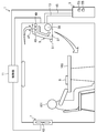
- FIG. 1 is a schematic view schematically showing an air conditioning system of an embodiment.
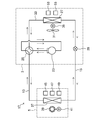
- FIG. 2 is a diagram showing a refrigerant circuit constituting the air conditioning system of the embodiment.
- FIG. 3 is a block diagram showing the configuration of the air conditioning system of the embodiment.
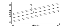
- FIG. 4 is an image diagram of related information (adaptive model of thermal comfort) used in the air conditioning system of the embodiment.
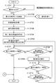
- FIG. 5 is a flowchart of the concentration maintaining mode during the cooling operation in the air conditioning system of the embodiment.
- FIG. 6 is a flowchart of the concentration maintaining mode during the heating operation in the air conditioning system of the embodiment.
- FIG. 7 is a flowchart of ventilation control in the concentration maintenance mode in the air conditioning system of the embodiment.
- Embodiment 1 The first embodiment will be described.
- the air-conditioning system (1) of the first embodiment is a system that contributes to maintaining the concentration of the occupants (101) on the work, and the occupants (101) such as an office or a study room perform the work. It is used to perform air conditioning for the room.
- the air conditioning system (1) includes an outdoor unit (3) installed outdoors, an indoor unit (5) and a ventilation device (7) installed indoors, and a remote controller (9). , Various sensors (45,47,49,51,53,55) and a control unit (11) that comprehensively controls the operation of the air conditioning system (1) are provided.
- the outdoor unit (3) and the indoor unit (5) are connected by connecting pipes (13, 15) to form a refrigerant circuit (17) shown in FIG.
- a vapor compression refrigeration cycle is performed by circulating the filled refrigerant.
- the refrigerant for example, R32 refrigerant is used.
- the refrigerant circuit (17) includes an outdoor circuit (19) and an indoor circuit (21).
- the outdoor unit (3) is installed outdoors, for example, on the roof of a building, on the ground beside a building, or on a balcony.
- the outdoor unit (3) has a compressor (23), a four-way switching valve (25), an outdoor heat exchanger (27), an expansion valve (29), and an outdoor fan (31).
- the compressor (23), the four-way switching valve (25), the outdoor heat exchanger (27), and the expansion valve (29) are connected in this order by the refrigerant pipe (33) to form the outdoor circuit (19).
- the compressor (23) compresses the sucked refrigerant and discharges the compressed refrigerant.
- the compressor (23) is configured as an inverter type having a variable capacity, for example.
- the compressor (23) is, for example, a rotary compressor.
- the outdoor fan (31) is installed near the outdoor heat exchanger (27).
- the outdoor fan (31) is driven by an outdoor fan motor (35).
- the outdoor fan (31) is composed of, for example, a propeller fan.
- the outdoor fan (31) conveys the outside air and passes it through the outdoor heat exchanger (27).
- the outdoor heat exchanger (27) exchanges heat between the outside air conveyed by the outdoor fan (31) and the refrigerant flowing inside.
- the outdoor heat exchanger (27) is composed of, for example, a fin-and-tube heat exchanger.
- the expansion valve (29) is a control valve having a variable opening degree.
- the expansion valve (29) depressurizes the refrigerant flowing inside.
- the expansion valve (29) is composed of, for example, an electronic expansion valve.
- the four-way switching valve (25) switches the flow path of the refrigerant in the refrigerant circuit (17) between the first state (the state shown by the solid line in FIG. 2) and the second state (the state shown by the broken line in FIG. 2).
- the four-way switching valve (25) in the first state communicates the discharge part of the compressor (23) with the outdoor heat exchanger (27), and connects the suction part of the compressor (23) with the indoor heat exchanger (37).
- the four-way switching valve (25) in the second state communicates the discharge part of the compressor (23) with the indoor heat exchanger (37), and connects the suction part of the compressor (23) with the outdoor heat exchanger (27). To communicate.
- the indoor unit (5) is attached to the wall or ceiling of the room, for example.
- the indoor unit (5) shown in FIG. 1 is a wall-mounted unit mounted on a wall surface.
- the indoor unit (5) has an indoor heat exchanger (37) and an indoor fan (39).
- the indoor heat exchanger (37) constitutes the indoor circuit (21).
- the indoor fan (39) is installed near the indoor heat exchanger (37).
- the indoor fan (39) is driven by the indoor fan motor (41).
- the indoor fan (39) is composed of, for example, a cross flow fan.
- the indoor fan (39) conveys the indoor air and passes it through the indoor heat exchanger (37).
- the indoor heat exchanger (37) exchanges heat between the indoor air conveyed by the indoor fan (39) and the refrigerant flowing inside.
- the indoor heat exchanger (37) is composed of, for example, a fin-and-tube heat exchanger.
- the indoor heat exchanger (37) is an example of a temperature control unit that regulates the temperature of the indoor air.
- the outdoor heat exchanger (27) functions as a condenser and the indoor heat exchanger (37) functions as a radiator (evaporator).
- a refrigeration cycle (a refrigeration cycle in which the refrigerant flows in the direction of the solid arrow in FIG. 2) is performed.
- the outdoor heat exchanger (27) functions as a radiator (evaporator) and the indoor heat exchanger (37) is a condenser.
- a refrigeration cycle (a refrigeration cycle in which the refrigerant flows in the direction of the broken arrow in FIG. 2) is performed.
- the ventilation device (7) is attached to the wall surface or ceiling of the room, for example.
- the ventilation device (7) shown in FIG. 1 is a wall-mounted device mounted on a wall surface.
- the ventilation device (7) has a ventilation fan (43) and, if necessary, a duct.
- the ventilation fan (43) takes in the outside air into the room and discharges the room air to the outside.
- the ventilation fan (43) is driven by a ventilation fan motor (not shown).
- the remote controller (9) is a separate part from the indoor unit (5) and may be placed near the occupant (101), such as on the desk (103) where the occupant (101) works. There are many.
- the remote controller (9) is configured to be operable by a resident (101). Although not shown, the remote controller (9) has an operation unit operated by the occupant (101) and a display unit for displaying predetermined information.
- the remote controller (9) is wirelessly connected to the control unit (11).
- the remote controller (9) outputs an operation signal to the control unit (9).
- the air conditioning system (1) can be turned on and off, the operation mode and control mode can be switched, the arousal strength can be set in the concentration maintenance mode described later, and the correction information regarding the reference temperature described later can be input.
- the operation unit has a plurality of buttons for performing these various operations.
- the plurality of buttons include a concentration button for turning on and off the concentration maintenance mode described later, and a selection button for setting the arousal strength.
- the "awakening strength” indicates the degree of the strength of the cool stimulus to the occupant (101) in the concentration maintenance mode. The details of the arousal strength setting will be described later.
- the correction information input by the operation unit is information related to individual differences of the occupants (101).
- the correction information may be information on the heat and cold experience of the occupant (101) (abstract information such as hot or cold). Further, the correction information may be information on a specific correction temperature such as + 1.0 ° C. or ⁇ 1.0 ° C. In addition, the correction information may be individual parameters related to the feeling of warmth and coldness such as gender, age, metabolic rate, body fat percentage, and blood pressure of the occupant (101).
- the set temperature (reference temperature), indoor air humidity, operation mode information, etc. are displayed on the display unit.
- the operation mode information includes whether the operation is cooling operation or heating operation, whether the concentration maintenance mode described later is being executed, and which of the awakening strengths is set in the concentration maintenance mode. Can be mentioned.
- the sensors include an inside air temperature sensor (45), an inside air humidity sensor (47), a CO 2 concentration sensor (49), an illuminance sensor (51), an outside air temperature sensor (53), and an outside air humidity sensor (55).
- Each of these sensors (45,47,49,51,53,55) is connected to the control unit (11) by wire or wirelessly.
- Each sensor (45,47,49,51,53,55) outputs a detection signal to the control unit (11).
- the indoor temperature sensor (47) is an example of the inside air temperature detection unit.
- the CO 2 concentration sensor (49) is an example of a carbon dioxide concentration detection unit.
- the inside air temperature sensor (45), the inside air humidity sensor (47), the CO 2 concentration sensor (49), and the illuminance sensor (51) are provided in, for example, the indoor unit (5).
- the indoor temperature sensor (45) detects the temperature of the indoor air sucked into the indoor unit (5).
- the indoor humidity sensor (47) detects the humidity of the indoor air sucked into the indoor unit (5).
- the CO 2 concentration sensor (49) detects the CO 2 concentration (carbon dioxide concentration) of the indoor air sucked into the indoor unit (5).
- the illuminance sensor (51) detects the brightness (illuminance) in the room.
- the outside air temperature sensor (53) and the outside air humidity sensor (55) are provided in, for example, the outdoor unit (3).
- the outside air temperature sensor (53) detects the temperature of the outside air sucked into the outdoor unit (3).
- the outside air humidity sensor (55) detects the humidity of the outside air sucked into the outdoor unit (3).
- the control unit (11) is a controller based on a well-known microcomputer. As shown in FIG. 3, the control unit (11) stores a central processing unit (CPU) (57) that executes a program and various programs and data executed on the central processing unit. It has a storage unit (59).
- the storage unit (59) is composed of a ROM (Read Only Memory), a RAM (Random Access Memory), and the like.
- the control unit (11) is built in, for example, the indoor unit (5).
- the control unit (11) detects the inside air temperature sensor (45), the inside air humidity sensor (47), the CO 2 concentration sensor (49), the illuminance sensor (51), the outside air temperature sensor (53), and the outside air humidity sensor (55). Based on the signal and the operation signal from the remote controller (9), the outdoor unit (3) (compressor (23), four-way switching valve (25), expansion valve (29), outdoor fan (31)), indoor unit ( 5) Calculate the control amount of (indoor fan (39)) and ventilation device (7) (ventilation fan (43)). The control unit (11) outputs a control signal related to the calculated control amount to the outdoor unit (3), the indoor unit (5), and the ventilation device (7).
- the storage unit (59) contains at least one of the humidity of the room air, the CO 2 concentration of the room air, the illuminance of the room, the outside air temperature and the outside air humidity, and the comfortable temperature of the room air that the occupant (101) feels comfortable with. Relationship information indicating the relationship with is stored.
- the relationship information for example, information on an adaptive model of thermal comfort known as an adaptive comfort model is used.
- the comfortable temperature of the occupant (101) fluctuates according to the outside air temperature depending on the ability of the person to adapt to the environment.
- the adaptive model of thermal comfort is a model obtained by regression analysis from statistical information based on the declaration of the temperature of the indoor air and the feeling of warmth and coldness of the occupant (101), and is represented by the graph of FIG. This is information showing the relationship between the outside air temperature and the comfortable temperature.
- the comfort temperature increases as the outside air temperature increases.
- the range between the upper and lower dash-dotted lines indicates the range of comfortable temperatures that 90% of humans feel comfortable statistically
- the range between the upper and lower dash-dotted lines is statistically comfortable for 80% of humans. It shows the range of comfortable temperature that you feel.
- the control unit (11) uses the relationship information stored in the storage unit (59), and in the first embodiment, the information of the adaptive model of thermal comfort, and is based on the outside air temperature detected by the outside air temperature sensor (53).
- the comfortable temperature of the occupant (101) is estimated.
- the concept of neutral temperature which is a temperature that human beings feel comfortable without being hot or cold, is known.
- the intermediate temperature shown by the solid line NL in the comfortable temperature range can be regarded as the neutral temperature.
- the control unit (11) estimates the neutral temperature obtained from the outside air temperature by this adaptive model of thermal comfort as the comfort temperature of the occupant (101).
- the control unit (11) automatically sets the reference temperature based on the estimated comfort temperature.
- the control unit (11) sets the estimated comfort temperature as the reference temperature when the correction information regarding the reference temperature is not input by the remote controller (9).
- the control unit (11) corrects the reference temperature based on the correction information.
- the reference temperature is corrected by a predetermined temperature, and the information that the occupant (101) is cold is input. If so, the correction is performed to raise the reference temperature by a predetermined temperature. Further, when specific correction temperature information is input as the correction information, the correction is performed to raise or lower the reference temperature according to the correction temperature. Further, when an individual parameter related to the feeling of warmth and coldness is input as the correction information, the correction is performed to raise or lower the reference temperature by a predetermined temperature determined according to the individual parameter.
- control unit (11) may be able to set the reference temperature based on the operation signal from the remote controller (9).
- the reference temperature may be manually set by the occupant operating the remote controller (9).
- the control unit (11) controls the operation of the outdoor unit (3) and the indoor unit (5) in the specified operation mode (cooling operation or heating operation) based on the operation signal from the remote controller (9).
- the operation of the air conditioning system (1) is controlled based on the detection signals from the various sensors (45,47,49,51,53,55) described above.
- the control unit (11) has a plurality of control modes, and is an outdoor unit (3), an indoor unit (5), and a ventilation device (7) according to the control mode set by the operation signal from the remote controller (9). Control the operation of.
- the control unit (11) has, as a control mode, a concentration maintenance mode for increasing the concentration of the occupant (101) and a normal operation mode for transitioning when the concentration maintenance mode is off.
- concentration maintenance mode is an example of the first mode.
- control unit (11) controls the operation of the ventilation device (7) based on the CO 2 concentration of the indoor air detected by the CO 2 sensor.
- the CO 2 concentration is one of the indexes for evaluating the indoor air quality. A high CO 2 concentration in the room air can lead to increased fatigue, fatigue, and drowsiness. Therefore, it is desirable that the CO 2 concentration in the indoor air does not become too high.
- the control unit (11) operates the ventilation device (7) when the CO 2 concentration in the room detected by the CO 2 concentration sensor (49) becomes equal to or higher than a predetermined first reference value.
- the first reference value is set to, for example, 1000 ppm according to a guideline set for environmental management of buildings.
- the control unit (11) stops the ventilation device (7) when the CO 2 concentration of the indoor air detected by the CO 2 concentration sensor (49) becomes less than a predetermined second reference value.
- the second reference value is set to, for example, 900 ppm.
- the air conditioning system (1) switches between cooling operation and heating operation according to the operation mode set by the remote controller (9) to adjust the temperature of the indoor air.
- the concentration maintenance mode can be executed by pressing the concentration button on the remote controller (9) and released by re-operating the concentration button in both the cooling operation and the heating operation.
- the four-way switching valve (25) is set to the first state.
- the refrigerant compressed by the compressor (23) is radiated (condensed) by the outdoor heat exchanger (27) that functions as a radiator.
- the radiated refrigerant is depressurized by the expansion valve (29) and then flows through the indoor heat exchanger (37) that functions as an evaporator.
- the indoor heat exchanger (37) the refrigerant absorbs heat from the indoor air and evaporates.
- the indoor air cooled by the indoor heat exchanger (37) is blown into the indoor space by the indoor fan (39).
- the evaporated refrigerant is sucked into the compressor (23).
- condensed water is generated near the indoor heat exchanger (37).
- the compressor (23) is stopped to operate the refrigerant circuit (17). Stop the indoor heat exchanger (37) so that the refrigerant does not flow. At this time, the indoor fan (39) is left in operation.
- the first temperature temperature difference between the temperature of the indoor air and the target temperature
- the indoor heat exchanger (37) is set to, for example, 1.0 ° C. The operation of the indoor heat exchanger (37) is restarted when the temperature detected by the inside air temperature sensor (45) reaches the target temperature.
- the four-way switching valve (25) is in the second state.
- the refrigerant compressed by the compressor (23) flows through the indoor heat exchanger (37), which functions as a radiator (condenser).
- the indoor heat exchanger (37) the refrigerant dissipates heat to the indoor air and condenses.
- the indoor air heated by the indoor heat exchanger (37) is blown into the indoor space by the indoor fan (39).
- the condensed refrigerant is depressurized by the expansion valve (29) and then evaporated by the outdoor heat exchanger (27). The evaporated refrigerant is sucked into the compressor (23).
- the compressor (23) is stopped to operate the refrigerant circuit (17). Stop the indoor heat exchanger (37) so that the refrigerant does not flow. At this time, the indoor fan (39) is left in operation.
- the second temperature temperature difference between the temperature of the indoor air and the target temperature
- the indoor heat exchanger (37) is set to, for example, 1.0 ° C. The operation of the indoor heat exchanger (37) is restarted when the temperature detected by the inside air temperature sensor (45) reaches the target temperature.
- ⁇ Normal operation mode> In the normal operation mode, the reference temperature is set to the target temperature. Since the reference temperature is changed according to the fluctuation of the outside air temperature detected by the outside air temperature sensor (53) according to the estimation control using the information of the adaptive model of thermal comfort, the target temperature is the fluctuation of the outside air temperature. It will be updated according to.
- the indoor heat exchanger (37) In the normal operation mode, the indoor heat exchanger (37) is controlled so that the temperature detected by the inside air temperature sensor (45) approaches the target temperature.
- the first operation and the second operation are performed at least once in order.
- the first operation is an operation of lowering the target temperature to a first target temperature lower than the reference temperature.
- the second operation is an operation of raising the target temperature to a second target temperature higher than the reference temperature.
- the time required to lower the target temperature to the first target temperature in the first operation is shorter than the time required to raise the target temperature to the second target temperature in the second operation. This will be clarified by the control in the first operation and the second operation described later.
- the indoor heat exchanger (37) is controlled so that the temperature detected by the inside air temperature sensor (45) approaches the first target temperature during the first operation, and the inside air is controlled during the second operation.
- the indoor heat exchanger (37) is controlled so that the temperature detected by the temperature sensor (45) approaches the second target temperature.
- the first target temperature and the second target temperature are determined according to the arousal intensity set by the remote controller (9).
- the setting of the arousal intensity is reflected in the amount of decrease in the first target temperature from the reference temperature and the amount of increase in the second target temperature from the reference temperature.
- the lowering range of the first target temperature and the raising range of the second target temperature are set so that, for example, the temperature difference between the first target temperature and the second target temperature is 3 ° C. or less. This is done because if the fluctuation range of the temperature of the indoor air exceeds 3 ° C., the body of the occupant (101) is burdened.
- the setting of the arousal strength "weak” is, for example, a setting in which the amount of decrease in the first target temperature from the reference temperature is 1.5 ° C. and the amount of increase in the second target temperature from the reference temperature is 1.5 ° C. ..
- the first target temperature is set to a temperature 1.5 ° C. lower than the reference temperature
- the second target temperature is set to a temperature 1.5 ° C. higher than the reference temperature.
- the amount of decrease in the first target temperature from the reference temperature is relatively small.
- the setting of the arousal strength "medium” is, for example, a setting in which the amount of decrease in the first target temperature from the reference temperature is 2.0 ° C. and the amount of increase in the second target temperature from the reference temperature is 1.0 ° C. ..
- the first target temperature is set to a temperature 2.0 ° C. lower than the reference temperature
- the second target temperature is set to a temperature 1.0 ° C. higher than the reference temperature.
- the amount of decrease in the first target temperature from the reference temperature is larger than that in the setting of the awakening intensity “weak”.
- the setting of the arousal strength "strong” is, for example, a setting in which the amount of decrease in the first target temperature from the reference temperature is 2.5 ° C. and the amount of increase in the second target temperature from the reference temperature is 0.5 ° C. ..
- the first target temperature is set to a temperature 2.5 ° C. lower than the reference temperature
- the second target temperature is set to a temperature 0.5 ° C. higher than the reference temperature.
- the amount of decrease in the first target temperature from the reference temperature is larger than that in the setting of the awakening strength “medium”.
- the target temperature is set to the first target temperature immediately after the start.
- the target temperature is not set to the second target temperature immediately after the start, but is gradually raised from the first target temperature to the second target temperature. Specifically, the target temperature is gradually raised by 0.5 ° C. every 30 seconds from the first target temperature to the second target temperature.
- the stepwise increase in the target temperature was set to 0.5 ° C because the first temperature (the temperature difference between the temperature of the indoor air and the target temperature), which is the reference for stopping the indoor heat exchanger (37), is 1.0. This is because it is set to ° C. According to such control, it is possible to prevent the indoor heat exchanger (37) from being stopped during the cooling operation.
- the execution time of the first operation and the execution time of the second operation are the temperature difference between the reference temperature Ta and the target temperature Ts for one period during which the first operation is performed, when the reference temperature is Ta and the target temperature is Ts.
- the integrated value of (Ta—Ts) is set to be equal to the integrated value of the temperature difference (Ts—Ta) between the target temperature Ts and the reference temperature Ta during the second operation.
- the execution time of the first operation and the execution time of the second operation are as follows: the reference temperature is Ta, the first target temperature is Ts1, the second target temperature is Ts2, the execution time of the first operation is ⁇ TL, and the first.
- the execution time of the two operations is ⁇ TH and the stepwise increase of the target temperature in the second operation is ⁇ Tr, the following relational expression (1) is satisfied.
- N (Ts2-Ts1) / ⁇ Tr. In addition, N> 1.
- the execution time ⁇ TL of the first operation is set to, for example, 4 minutes or less. This is because, in an environment where the temperature of the indoor air is cool, the resident (101) tends to feel cold when the duration of stay exceeds 4 minutes. In the first embodiment, the execution time ( ⁇ TL) of the first operation is set to, for example, 4 minutes.
- the execution time ⁇ TH of the second operation is set according to the setting of the arousal strength based on the above relational expression (1).
- Awakening strength "weak" setting (1st target temperature Ts1 decrease from reference temperature Ta is 1.5 ° C, 2nd target temperature Ts2 increase from reference temperature Ta is 1.5 ° C, 1st operation
- the execution time ⁇ TL is 4 minutes and the stepwise increase width ⁇ Tr of the target temperature in the second operation is 0.5 minutes
- the execution time ⁇ TH of the second operation is 6.5 from the above relational expression (1). Set to minutes.
- Awakening strength "medium” setting (1st target temperature Ts1 decrease from reference temperature Ta is 2.0 ° C, 2nd target temperature Ts2 increase from reference temperature Ta is 1.0 ° C, 1st operation
- the execution time ⁇ TL is 4 minutes and the stepwise increase width ⁇ Tr of the target temperature in the second operation is 0.5 minutes
- the execution time ⁇ TH of the second operation is 11.75 from the above relational expression (1). Set to minutes.
- the execution time ⁇ TL is 4 minutes and the stepwise increase width ⁇ Tr of the target temperature in the second operation is 0.5 minutes
- the execution time ⁇ TH of the second operation is 27.5 from the above relational expression (1). Set to minutes.
- step C-ST01 in the cooling operation, first, in step C-ST01 after startup, it is determined whether or not the centralized button is pressed based on the operation signal from the remote controller (9). If it is determined in step C-ST01 that the centralized button is not pressed (NO), the user returns and repeats step C-ST01 to monitor that the centralized button is pressed.
- step C-ST01 If it is determined that the concentration button has been pressed in this step C-ST01 (YES), the process proceeds to the next step C-ST02. In step C-ST02, the execution of the concentration maintenance mode is started. Then, the process proceeds to step C-ST03. Further, at the same time as the steps after step C-ST03, the ventilation control described later is executed.
- step C-ST03 the detection signals of various sensors (45,47,49,51,53,55) are read, and indoor and outdoor such as indoor air temperature, indoor air humidity, indoor illuminance, outside air temperature and outside air humidity are read.
- indoor and outdoor such as indoor air temperature, indoor air humidity, indoor illuminance, outside air temperature and outside air humidity are read.
- the setting information by the remote controller (9) is read, and the correction information of the occupant (101) regarding the reference temperature and the setting information of the arousal strength are acquired. Then, the process proceeds to step C-ST04.
- step C-ST04 the comfort temperature (neutral temperature) of the occupant (101) was estimated and estimated based on the outside air temperature acquired in step C-ST03 using the information of the adaptive model of thermal comfort. Set the comfortable temperature to the reference temperature. At this time, if the correction information regarding the reference temperature is set by the remote controller (9), the reference temperature is corrected based on the correction information. Then, the process proceeds to step C-ST05.
- step C-ST05 the first target temperature and the second target temperature are set based on the reference temperature set in step C-ST04 and the setting information of the arousal intensity acquired in step C-ST03.
- the execution time ⁇ TL of the first operation and the execution time ⁇ TH of the second operation are determined based on the setting information of the arousal strength acquired in step C-ST03. Then, the process proceeds to step C-ST06.
- step C-ST06 the execution of the first operation is started and the target temperature is set to the first target temperature.
- the temperature of the indoor air is quickly lowered to be lower than the reference temperature. Therefore, the indoor temperature is set as the temperature at which the occupant (101) feels cool, and the wakefulness strength is set for the occupant (101). A cool stimulus is given according to the temperature. Then, the process proceeds to step C-ST07.
- step C-ST07 it is determined whether or not the concentration button is pressed again on the remote controller (9) to cancel the concentration maintenance mode.
- the concentration maintenance mode is terminated and the normal operation mode is entered. If it is determined in step C-ST07 that the concentration maintenance mode has not been released (NO), the process proceeds to step C-ST08.
- step C-ST08 it is determined whether or not the execution time ( ⁇ TL) of the first operation has elapsed. If it is determined in step C-ST08 that the execution time ( ⁇ TL) of the first operation has not elapsed (NO), the process returns to step C-ST07, and the concentration maintenance mode is canceled or the first operation is performed. Step C-ST07 and step C-ST08 are repeated until the execution time of is elapsed. If it is determined in step C-ST08 that the execution time ( ⁇ TL) of the first operation has elapsed (YES), the process proceeds to step C-ST09.
- step C-ST09 the execution of the second operation is started instead of the first operation, and the target temperature is gradually raised from the first target temperature to the second target temperature.
- the target temperature is set higher than the temperature detected by the inside air temperature sensor (45) by the first temperature (1.0 ° C.) or more, the indoor heat exchanger (37) is stopped, but the indoor fan (indoor fan ( 39) is ready to drive. In that case, the moisture adhering to the indoor heat exchanger (37) is released into the room by blowing air, so that the humidity of the indoor air rises, which may cause discomfort to the occupant (101).
- the target temperature is gradually raised by 0.5 ° C. every 30 seconds from the first target temperature to the second target temperature, so that the temperature detected by the inside air temperature sensor (45). Is unlikely to be lower than the target temperature by the first temperature (1.0 ° C.) or more, and the indoor heat exchanger (37) can be prevented from stopping.
- step C-ST10 it is determined whether or not the concentration button is pressed again on the remote controller (9) to cancel the concentration maintenance mode.
- the concentration maintenance mode is terminated and the normal operation mode is entered. If it is determined in step C-ST10 that the concentration maintenance mode has not been released (NO), the process proceeds to step C-ST11.
- step C-ST11 it is determined whether or not the execution time ( ⁇ TH) of the second operation has elapsed. If it is determined in step C-ST11 that the execution time ( ⁇ TH) of the second operation has not elapsed (NO), the process returns to step C-ST10, and the concentration maintenance mode is canceled or the second operation is performed. Step C-ST10 and step C-ST11 are repeated until the execution time ( ⁇ TH) of is elapsed. When it is determined in step C-ST11 that the execution time ( ⁇ TH) of the second operation has elapsed (YES), the process returns to step C-ST06 and the execution of the first operation is started instead of the second operation. ..
- the repeated operation of the first operation and the second operation in the concentration maintenance mode during the cooling operation is executed until the occupant (101) operates the remote controller (9) to release the concentration maintenance mode.
- the average temperature of the indoor air in the total period of one cycle in which the first operation and the second operation are performed once while periodically giving a cool stimulus to the occupants is calculated. Adjusted to a comfortable temperature.
- the concentration maintenance mode during the heating operation by the air conditioning system (1) is executed according to the flowchart shown in FIG.
- step H-ST01 in the heating operation, first, in step H-ST01 after startup, it is determined whether or not the centralized button is pressed based on the operation signal from the remote controller (9). If it is determined in step H-ST01 that the concentrated button is not pressed (NO), the process returns and the step C-ST01 is repeated to monitor that the concentrated button is pressed.
- step H-ST01 If it is determined that the concentrated button has been pressed in this step H-ST01 (YES), the process proceeds to the next step H-ST02. In step C-ST02, the concentration maintenance mode is started. Then, the process proceeds to step H-ST03. Further, at the same time as the steps after step H-ST03, the ventilation control described later is executed.
- step H-ST03 the detection signals of various sensors (45,47,49,51,53,55) are read, and indoor and outdoor such as indoor air temperature, indoor air humidity, indoor illuminance, outside air temperature and outside air humidity are read.
- indoor and outdoor such as indoor air temperature, indoor air humidity, indoor illuminance, outside air temperature and outside air humidity are read.
- the setting information by the remote controller (9) is read, and the correction information regarding the reference temperature and the setting information of the arousal intensity are acquired. Then, the process proceeds to step H-ST04.
- step H-ST04 the comfort temperature (neutral temperature) of the occupant (101) was estimated and estimated based on the outside air temperature acquired in step H-ST03 using the information of the adaptive model of thermal comfort. Set the comfortable temperature to the reference temperature. At this time, if the correction information regarding the reference temperature is set by the remote controller (9), the reference temperature is corrected based on the correction information.
- step H-ST05 the first target temperature and the second target temperature are set based on the reference temperature set in step H-ST04 and the setting information of the arousal intensity acquired in step H-ST03.
- the execution time ⁇ TL of the first operation and the execution time ⁇ TH of the second operation are determined based on the setting information of the arousal strength acquired in step C-ST03. Then, the process proceeds to step H-ST06.
- step H-ST06 the execution of the first operation is started and the target temperature is set to the first target temperature.
- the inside air temperature sensor (45) immediately after the execution of the first operation is started.
- the temperature detected by) becomes higher than the second target temperature by the first temperature (1.0 ° C.) or more, and the indoor heat exchanger (37) is stopped.
- the temperature of the indoor air is quickly lowered to be lower than the reference temperature. Therefore, the temperature of the indoor air is set as the temperature at which the occupant (101) feels cool, and the occupant (101) is awakened.
- a cool stimulus is given according to the setting of.
- the operation of the indoor heat exchanger (37) is restarted. Then, the process proceeds to step H-ST07.
- step H-ST07 it is determined whether or not the concentration button is pressed on the remote controller (9) to cancel the concentration maintenance mode.
- the concentration maintenance mode is terminated and the normal operation mode is entered. If it is determined in step H-ST07 that the concentration maintenance mode has not been released (NO), the process proceeds to step H-ST08.
- step H-ST08 it is determined whether or not the execution time ( ⁇ TL) of the first operation has elapsed. If it is determined in step H-ST08 that the execution time ( ⁇ TL) of the first operation has not elapsed (NO), the process returns to step H-ST07, and the concentration maintenance mode is canceled or the first operation is performed. Step H-ST07 and step H-ST08 are repeated until the execution time ( ⁇ TL) of is elapsed. If it is determined in step H-ST08 that the execution time ( ⁇ TL) of the first operation has elapsed (YES), the process proceeds to step H-ST09.
- step H-ST09 the execution of the second operation is started instead of the first operation, and the target temperature is gradually raised from the first target temperature to the second target temperature.
- the target temperature is suddenly raised from the first target temperature to the second target temperature, the temperature of the indoor air will rise sharply due to the heating operation of the air conditioning system.
- the temperature of the indoor air rises sharply, the blood vessels of the occupant (101) are dilated and the heat dissipation of the body is promoted, so that the core body temperature decreases and the occupant (101) tends to feel drowsy.
- the target temperature is gradually raised by 0.5 ° C. every 30 seconds from the first target temperature to the second target temperature, so that the blood vessels of the occupant (101) expand. It is possible to prevent the occupant (101) from feeling drowsy easily.
- step H-ST10 it is determined whether or not the concentration button is pressed again on the remote controller (9) to cancel the concentration maintenance mode.
- the concentration maintenance mode is terminated and the normal operation mode is entered. If it is determined in step H-ST10 that the concentration maintenance mode has not been released (NO), the process proceeds to step H-ST11.
- step H-ST12 it is determined whether or not the execution time ( ⁇ TH) of the second operation has elapsed. If it is determined in step H-ST12 that the execution time ( ⁇ TH) of the second operation has not elapsed (NO), the process returns to step H-ST11 and the concentration maintenance mode is canceled or the second operation is performed. Step C-ST11 and step H-ST12 are repeated until the execution time ( ⁇ TH) of is elapsed. When it is determined in step H-ST12 that the execution time ( ⁇ TH) of the second operation has elapsed (YES), the process returns to step H-ST06 and the execution of the first operation is started instead of the second operation. ..
- the repeated operation of the first operation and the second operation in the concentration maintenance mode during the heating operation is executed until the occupant (101) operates the remote controller (9) to release the concentration maintenance mode.
- the average temperature of the indoor air in the total period of one cycle in which the first operation and the second operation are performed once while periodically giving a cool stimulus to the occupants is calculated. Adjusted to a comfortable temperature.
- the control in the concentration maintenance mode during the cooling operation and the control in the concentration maintenance mode during the heating operation are almost the same, but the first operation in the concentration maintenance mode during the cooling operation is The first operation in the concentration maintenance mode during the heating operation is performed by stopping the indoor heat exchanger (37), while the indoor heat exchanger (37) is not stopped.
- the second operation in the concentration maintenance mode during heating gradually raises the target temperature in order to avoid stopping the indoor heat exchanger (37), whereas the second operation in the concentration maintenance mode during heating operation is The difference is that the target temperature is gradually increased to prevent the occupant (101) from becoming drowsy.
- Ventilation control by the air conditioning system (1) is executed according to the flowchart shown in FIG.
- the ventilation control is performed in the concentration maintenance mode in step C-ST02 in the concentration maintenance mode during the cooling operation or in step H-ST02 in the concentration maintenance mode during the heating operation. It is executed as soon as the execution is started.
- step V-ST01 it is determined whether or not the concentration button is pressed again on the remote controller (9) to cancel the concentration maintenance mode.
- the concentration maintenance mode is terminated and the normal operation mode is entered (see FIGS. 5 and 6). If it is determined in step V-ST01 that the concentration maintenance mode has not been released (NO), the process proceeds to step V-ST02.
- Step V-ST02 acquires the CO 2 concentration in the indoor air detected by the CO 2 concentration sensor (49). Then, the process proceeds to step V-ST03.
- step V-ST03 it is determined whether or not the CO 2 concentration of the indoor air is equal to or higher than the first reference value (1000 ppm). If it is determined in step V-ST03 that the CO 2 concentration of the indoor air is less than the first reference value (1000 ppm) (NO), the process returns to step V-ST01 and the concentration maintenance mode is released or Steps V-ST01 to V-ST03 are repeated until the CO 2 concentration in the room air becomes equal to or higher than the first reference value (1000 ppm).
- step V-ST03 If it is determined in step V-ST03 that the CO 2 concentration in the room air is equal to or higher than the first reference value (1000 ppm) (YES), the process proceeds to step V-ST04. In step C-ST04, the operation of the ventilation device (7) is started. Then, the process proceeds to step V-ST05.
- step V-ST05 it is determined whether or not the concentration button is pressed again on the remote controller (9) to cancel the concentration maintenance mode.
- the concentration maintenance mode is terminated and the normal operation mode is entered (see FIGS. 5 and 6). If it is determined in step V-ST05 that the concentration maintenance mode has not been released (NO), the process proceeds to step V-ST06.
- Step V-ST06 acquires the CO 2 concentration in the indoor air detected by the CO 2 concentration sensor (49). Then, the process proceeds to step V-ST07.
- step V-ST07 it is determined whether or not the CO 2 concentration of the indoor air is less than the second reference value (900 ppm). If it is determined in step V-ST07 that the CO 2 concentration in the room air is equal to or higher than the second reference value (900 ppm) (NO), the process returns to step V-ST04 and the concentration maintenance mode is released or Steps V-ST04 to V-ST07 are repeated until the CO 2 concentration in the room air becomes less than the second reference value (900 ppm).
- step V-ST07 If it is determined in step V-ST07 that the CO 2 concentration in the room air is less than the second reference value (900 ppm) (YES), the process returns and the steps after step V-ST01 are performed again.
- the ventilation control is executed until the concentration maintenance mode is released. According to the execution of this ventilation control, the CO 2 concentration of the indoor air is adjusted to the first reference value (1000 ppm) or less.
- the target temperature is lowered to the first target temperature in a relatively short time in the first operation.
- the temperature of the indoor air is quickly lowered and becomes lower than the reference temperature. Therefore, the indoor temperature is set to a temperature at which the occupant (101) feels cool, and the occupant (101) is stimulated to cool. Is given. As a result, it is possible to prevent the occupant (101) from feeling drowsy.
- the target temperature is gradually raised to the second target temperature in the second operation over a relatively long time.
- the temperature of the indoor air is gradually raised to be higher than the reference temperature, so that the period during which the first operation is performed and the second operation while reducing the burden on the occupant (101) due to the temperature change.
- the average temperature of the indoor air during the total period of the operation can be set to a comfortable temperature for the occupant (101). As a result, the occupant (101) can realize a comfortable indoor environment.
- the air conditioning system (1) of the first embodiment it is possible to both prevent the occupants from feeling drowsy and realize a comfortable indoor environment. As a result, it is possible to maintain the concentration of the occupants and suppress the deterioration of the work efficiency of the occupants.
- the indoor heat exchanger ( 37) Stop.
- the target temperature is gradually raised from the first target temperature to the second target temperature, so that the temperature detected by the inside air temperature sensor (45) is a predetermined temperature higher than the target temperature during the cooling operation. It is difficult to lower the temperature, and it is possible to prevent the indoor heat exchanger (37) from being stopped. As a result, it is possible to prevent the occupant (101) from being uncomfortable due to the increase in the humidity of the indoor air.
- the air conditioning system (1) of the first embodiment when the temperature detected by the inside air temperature sensor (45) becomes higher than the target temperature by the first temperature (1.0 ° C.) or more during the heating operation. , Stop the indoor heat exchanger (37).
- the first target temperature is set lower than the temperature detected by the inside air temperature sensor (45) by the first temperature (1.0 ° C.) or more.
- the indoor heat exchanger (37) is stopped shortly after the first operation is started, which contributes to promptly lowering the temperature of the indoor air.
- the comfortable temperature is estimated and estimated from the outside air temperature detected by the outside air temperature sensor (45) by using the relational information indicating the relationship between the comfortable temperature and the outside air temperature.
- the comfortable temperature is used as the reference temperature.
- the general comfortable temperature can be estimated as the temperature of the indoor air that the occupant (101) feels comfortable, and can be set as the reference temperature. This is suitable for realizing a comfortable indoor environment for an unspecified resident (101) by controlling the temperature of the indoor air in the first mode.
- the reference temperature is corrected based on the information regarding the individual difference of the occupants (101).
- information on individual differences of the occupants (101) is reflected in the reference temperature, so that the temperature of the indoor air that the occupants (101) feel comfortable with can be used accurately as the reference temperature.
- This is advantageous for realizing a comfortable indoor environment for the occupant (101) by controlling the temperature of the indoor air in the concentration maintenance mode.
- the target temperature and execution time of the first operation and the target temperature and execution time of the second operation perform the first operation according to the above relational expression (1).
- the average temperature of the indoor air during the total period of one period during which the operation is performed and the period during which the second operation is performed is determined to be the reference temperature. This is suitable for realizing a comfortable indoor environment for the occupant (101) by controlling the temperature of the indoor air in the concentration maintenance mode.
- the ventilation device (7 ) when the CO 2 concentration of the room air detected by the CO 2 concentration sensor (49) becomes a first reference value (1000 ppm) or more, the ventilation device (7 ). According to this, since the indoor air is replaced as needed and the CO 2 concentration in the room is lowered, it is suitable for realizing a comfortable indoor environment for the occupant (101).
- Embodiment 2 The second embodiment will be described.
- the air-conditioning system (1) of the second embodiment is a modification of the reference temperature setting method in the air-conditioning system (1) of the first embodiment.
- the difference between the air conditioning system (1) of the second embodiment and the air conditioning system (1) of the first embodiment will be described.
- the air conditioning system (1) uses artificial intelligence (AI: Artificial Intelligence) to set the reference temperature.
- AI Artificial Intelligence
- the storage unit (59) of the air conditioning system (1) contains parameters related to environmental information including at least one of indoor temperature, indoor humidity, indoor illuminance, outside air temperature and outside air humidity, and occupants (101).
- the learning model generated based on the parameters related to the hot and cold feeling of) is stored.
- the parameters related to the environmental information of the learning model include parameters related to indoor temperature, indoor humidity, indoor illuminance, outside air temperature, and outside air humidity.
- the information on the hot and cold feeling of the occupant (101) is input by the operation of the remote controller (9).
- the detected values of the inside air temperature sensor (45), inside air humidity sensor (47), illuminance sensor (51), outside air temperature sensor (53), and outside air humidity sensor (55) as parameters of environmental information the occupants (101) ) May be generated by stand-alone learning associated with the hot and cold sensation parameters.
- the learning model is an inside air temperature sensor (45) and inside air humidity collected from occupants (101) who use each air conditioning system (1) in a server connected to a plurality of air conditioning systems (1) via a network.
- the detected values of the sensor (47), the illuminance sensor (51), the outside air temperature sensor (53), and the outside air humidity sensor (55), and the information on the hot and cold feeling of the occupant (101) are the parameters of the environmental information. And it may be generated by learning to associate it as a parameter related to the warmth and coldness of the occupant (101).
- the control unit (11) is detected by the inside air temperature sensor (45), the inside air humidity sensor (47), the illuminance sensor (49), the outside air temperature sensor (53) and the outside air humidity sensor (55) using the above learning model.
- the comfortable temperature is estimated based on the indoor temperature, indoor humidity, indoor illuminance, outside air temperature and outside air humidity.
- the control unit (11) sets the comfortable temperature estimated by the learning model as the reference temperature.
- the control unit (11) corrects the reference temperature based on the correction information regarding the reference temperature as necessary.
- the comfortable temperature used as the reference temperature is estimated by a learning model that associates the environmental information with the warm / cold feeling of the occupant (101).
- the temperature of the indoor air that the occupant (101) feels comfortable can be accurately estimated as the comfortable temperature and set as the reference temperature. This is advantageous for realizing a comfortable indoor environment for the occupant (101) by controlling the temperature of the indoor air in the concentration maintenance mode.
- the above-described first embodiment and the above-mentioned second embodiment may have the following configurations.
- the inside air temperature sensor (45) may be provided on the remote controller (9). In this way, since the remote controller (9) is often placed near the occupant (101), the temperature of the indoor air in the vicinity of the occupant (101) can be detected. This is advantageous for realizing a comfortable indoor environment for the occupant (101) by controlling the temperature of the indoor air in the concentration maintenance mode.
- the inside air temperature sensor (45) does not have to be the remote controller (9), but may be provided as a separate component from the indoor unit (5).
- the inside air humidity sensor (47), illuminance sensor (49), and CO 2 concentration sensor (51) are also separate from the indoor unit (5) such as the remote controller (9). It may be provided on the component.
- the model may be owned by a server connected to the air conditioning system (1) via a network.
- the air conditioning system (1) may request the server for the relationship information and the learning model information, and acquire the information necessary for setting the reference temperature from the server.
- the air conditioning system (1) has been described by taking as an example a case where the outdoor unit (3) and the indoor unit (5) are in a one-to-one pair type, but the present invention is not limited to this.
- the air conditioning system (1) may be a multi-type in which a plurality of indoor units (5) are provided with respect to the outdoor unit (3).
- the target temperature was lowered to the first target temperature immediately after the start, but this is not limited to this.
- 1000 ppm is used as the first reference value of the CO 2 concentration for operating the ventilation device (7)
- 900 ppm is used as the second reference value for the CO 2 concentration for stopping the ventilation device (7).
- the present invention is not limited to this. Setting the first reference value to 1000 ppm and setting the second reference value to 900 ppm is only an example of the setting for performing ventilation control, and these first reference value and the second reference value are present. Any value can be set as long as it is suitable for realizing a comfortable indoor environment for the room person.
- this disclosure is useful for air conditioning systems.
- Air conditioning system Outdoor unit 5 Indoor unit 7 Ventilation device 9 Remote controller (input section) 11 Control unit 13 Communication piping 15 Communication piping 17 Refrigerant circuit 19 Outdoor circuit 21 Indoor circuit 23 Compressor 25 Four-way switching valve 27 Outdoor heat exchanger 29 Expansion valve 31 Outdoor fan 33 Refrigerant piping 35 Outdoor fan motor 37 Indoor heat exchanger (temperature) Adjustment part) 39 Indoor fan 41 Indoor fan motor 43 Ventilation fan 45 Inside air temperature sensor (inside air temperature detector) 47 Inside air humidity sensor 49 CO 2 concentration sensor (carbon dioxide concentration detector) 51 Illuminance sensor 53 Outside air temperature sensor (outside air temperature detector) 55 Outside air humidity sensor 57 Central processing unit 59 Memory 101 Resident 103 Desk
Abstract
The purpose of the present disclosure is to both prevent a room occupant from feeling sleepiness and realize a comfortable indoor environment. In the present invention, an air conditioner system (1) executes a concentration-maintaining mode in which the following operations are sequentially performed in repetition: a first operation of reducing the target temperature to a first target temperature lower than a prescribed reference temperature; and a second operation of increasing the target temperature to a second target temperature higher than the reference temperature. In the second operation, the target temperature is gradually increased from the first target temperature to the second target temperature. The time taken for the target temperature to be reduced to the first target temperature in the first operation is made less than the time taken for the target temperature to be increased to the second target temperature in the second operation.
Description
本開示は、空調システムに関するものである。
This disclosure relates to an air conditioning system.
従来から、空調システムにおいて、在室者の体感温度や温熱快適性に基づき、温度、湿度および風速などを制御することにより、室内環境の快適性を向上させる技術が提案されている(例えば、特許文献1参照)。在室者の体感温度を示す指標としてはSET(Standard new Effective Temperature)が、在室者の温熱快適性を示す指標としてはPMV(Predicted Mean Vote)がそれぞれ知られている。
Conventionally, in an air conditioning system, a technique for improving the comfort of an indoor environment by controlling the temperature, humidity, wind speed, etc. based on the sensible temperature and thermal comfort of a resident has been proposed (for example, a patent). Reference 1). SET (Standard new Effective Temperature) is known as an index showing the sensible temperature of the occupants, and PMV (Predicted Mean Vote) is known as an index showing the thermal comfort of the occupants.
空調システムによって実現される在室者が快適と感じる環境の中には、人が眠気を感じる環境条件が存在する。このため、オフィスや自習室などの作業環境においては、在室者が一定温度の快適な環境に滞在し続けると、集中力が低下して作業効率を悪化させるおそれがある。
In the environment realized by the air conditioning system that the occupants feel comfortable, there are environmental conditions that make people feel drowsy. Therefore, in a work environment such as an office or a self-study room, if the occupants continue to stay in a comfortable environment at a constant temperature, their concentration may decrease and their work efficiency may deteriorate.
本開示の目的は、在室者が眠気を感じるのを防止することと、快適な室内環境を実現することとを両立することにある。
The purpose of the present disclosure is to both prevent the occupants from feeling drowsy and to realize a comfortable indoor environment.
本開示の第1の態様は、室内空気の温度を調節する温度調節部(37)と、室内空気の温度を検出する内気温度検出部(45)と、内気温度検出部(45)によって検出される温度が目標温度に近づくように温度調節部(37)を制御する制御部(11)とを備える空調システム(1)を対象とする。
The first aspect of the present disclosure is detected by a temperature control unit (37) that regulates the temperature of the room air, an inside air temperature detection unit (45) that detects the temperature of the room air, and an inside air temperature detection unit (45). The target is an air conditioning system (1) equipped with a control unit (11) that controls a temperature control unit (37) so that the temperature approaches the target temperature.
制御部(11)は、目標温度を所定の基準温度よりも低い第1目標温度に下げる第1動作と、目標温度を基準温度よりも高い第2目標温度に上げる第2動作とを順に少なくとも1回ずつ行う第1モードを実行する。第2動作では、目標温度を第1目標温度から第2目標温度にまで徐々に上げる。第1動作において目標温度を第1目標温度に下げるまでの時間は、第2動作において目標温度を第2目標温度に上げるまでの時間よりも短い。
The control unit (11) sequentially performs at least one first operation of lowering the target temperature to a first target temperature lower than a predetermined reference temperature and a second operation of raising the target temperature to a second target temperature higher than the reference temperature. The first mode, which is performed once, is executed. In the second operation, the target temperature is gradually raised from the first target temperature to the second target temperature. The time required to lower the target temperature to the first target temperature in the first operation is shorter than the time required to raise the target temperature to the second target temperature in the second operation.
この第1の態様では、第1動作において目標温度を相対的に短い時間で第1目標温度に下げる。そのことで、室内空気の温度が速やかに下げられて基準温度よりも低くなるから、室内温度を在室者(101)が涼しさを感じる温度にして、在室者(101)に冷涼な刺激を与えられる。これにより、在室者(101)が眠気を感じるのを防止することができる。
In this first aspect, the target temperature is lowered to the first target temperature in a relatively short time in the first operation. As a result, the temperature of the indoor air is quickly lowered and becomes lower than the reference temperature. Therefore, the indoor temperature is set to a temperature at which the occupant (101) feels cool, and the occupant (101) is stimulated to cool. Is given. As a result, it is possible to prevent the occupant (101) from feeling drowsy.
また、この第1の態様では、第2動作において目標温度を相対的に長い時間をかけて徐々に第2目標温度に上げる。そのことで、室内空気の温度が緩やかに上げられて基準温度よりも高くなるので、温度変化によって在室者(101)にかかる負担を軽減しながら、第1動作を行っている期間と第2動作を行っている期間との総期間における室内空気の平均温度を在室者(101)が快適な温度とすることができる。これにより、在室者(101)にとって快適な室内環境を実現することができる。
Further, in this first aspect, in the second operation, the target temperature is gradually raised to the second target temperature over a relatively long time. As a result, the temperature of the indoor air is gradually raised to be higher than the reference temperature, so that the period during which the first operation is performed and the second operation while reducing the burden on the occupant (101) due to the temperature change. The average temperature of the indoor air during the total period of the operation can be set to a comfortable temperature for the occupant (101). As a result, a comfortable indoor environment can be realized for the occupant (101).
本開示の第2の態様は、第1の態様の空調システム(1)において、温度調節部(37)が、冷媒回路(17)に接続される室内熱交換器(37)によって構成されている、空調システム(1)である。制御部(11)は、室内熱交換器(37)が蒸発器として機能する冷房運転時に第1モードを実行する。そして、制御部(11)は、内気温度検出部(45)によって検出される温度が目標温度よりも所定の温度以上低くなったときに、室内熱交換器(37)を停止させる。
In the second aspect of the present disclosure, in the air conditioning system (1) of the first aspect, the temperature control unit (37) is configured by an indoor heat exchanger (37) connected to a refrigerant circuit (17). , Air conditioning system (1). The control unit (11) executes the first mode during the cooling operation in which the indoor heat exchanger (37) functions as an evaporator. Then, the control unit (11) stops the indoor heat exchanger (37) when the temperature detected by the inside air temperature detection unit (45) becomes lower than the target temperature by a predetermined temperature or more.
この第2の態様では、冷房運転時において、内気温度検出部(45)により検出される温度が目標温度よりも所定の温度以上低くなったときに、室内熱交換器(37)を停止する。そのため、冷房運転時において、目標温度が内気温度検出部(45)によって検出される温度よりも所定の温度以上高く設定された場合、室内熱交換器(37)が停止されるが室内ファン(39)は運転する状態になり得る。そうなると、室内熱交換器(37)に付着した水分が送風によって室内に放たれるため、室内空気の湿度が上がり、在室者(101)に不快感を与えてしまう。
In this second aspect, the indoor heat exchanger (37) is stopped when the temperature detected by the inside air temperature detection unit (45) becomes lower than the target temperature by a predetermined temperature or more during the cooling operation. Therefore, during the cooling operation, if the target temperature is set higher than the temperature detected by the inside air temperature detection unit (45) by a predetermined temperature or higher, the indoor heat exchanger (37) is stopped, but the indoor fan (39) is stopped. ) Can be in a driving state. In that case, the moisture adhering to the indoor heat exchanger (37) is released into the room by blowing air, so that the humidity of the indoor air rises, which causes discomfort to the occupant (101).
これに対し、この第2の態様においても、第2動作では、目標温度を第1目標温度から第2目標温度にまで徐々に上げるので、冷房運転時において、内気温度検出部(45)により検出される温度が目標温度よりも所定温度以上低くなり難くし、室内熱交換器(37)が停止されるのを抑制できる。これにより、室内空気の湿度が上がることに起因して在室者(101)に不快感を与えないようにできる。
On the other hand, also in this second aspect, in the second operation, the target temperature is gradually raised from the first target temperature to the second target temperature, so that it is detected by the inside air temperature detection unit (45) during the cooling operation. It is difficult for the temperature to be set to be lower than the target temperature by a predetermined temperature or higher, and it is possible to prevent the indoor heat exchanger (37) from being stopped. As a result, it is possible to prevent the occupant (101) from being uncomfortable due to the increase in the humidity of the indoor air.
本開示の第3の態様は、第1の態様の空調システム(1)において、温度調節部(37)が、冷媒回路(17)に接続される室内熱交換器(37)によって構成されている、空調システム(1)である。制御部(11)は、室内熱交換器(37)が放熱部として機能する暖房運転時に第1モードを実行する。そして、制御部(11)は、内気温度検出部(45)によって検出される温度が目標温度よりも所定の温度以上高くなったときに、室内熱交換器(37)を停止させる。
In the third aspect of the present disclosure, in the air conditioning system (1) of the first aspect, the temperature control unit (37) is configured by an indoor heat exchanger (37) connected to a refrigerant circuit (17). , Air conditioning system (1). The control unit (11) executes the first mode during the heating operation in which the indoor heat exchanger (37) functions as a heat dissipation unit. Then, the control unit (11) stops the indoor heat exchanger (37) when the temperature detected by the inside air temperature detection unit (45) becomes higher than the target temperature by a predetermined temperature or more.
この第3の態様では、暖房運転時において、内気温度検出部(45)により検出される温度が目標温度よりも所定の温度以上高くなったときに、室内熱交換器(37)を停止する。第1動作では、目標温度を相対的に短い時間で第1目標温度に下げるから、第1目標温度が内気温度検出部(45)によって検出される温度よりも所定の温度以上低く設定され易い。このことは、第1動作を開始した後に間もなく室内熱交換器(37)を停止し、室内空気の温度を速やかに下げるのに寄与する。
In this third aspect, the indoor heat exchanger (37) is stopped when the temperature detected by the inside air temperature detection unit (45) becomes higher than the target temperature by a predetermined temperature or more during the heating operation. In the first operation, since the target temperature is lowered to the first target temperature in a relatively short time, the first target temperature is likely to be set lower than the temperature detected by the inside air temperature detection unit (45) by a predetermined temperature or more. This contributes to stopping the indoor heat exchanger (37) shortly after starting the first operation and rapidly lowering the temperature of the indoor air.
本開示の第4の態様は、第1~第3の態様のいずれか1つの空調システム(1)において、制御部(11)が、在室者(101)が快適と感じる室内空気の快適温度を推定する、空調システム(1)である。ここで、基準温度は、制御部(11)によって推定される快適温度である。
A fourth aspect of the present disclosure is the comfortable temperature of the indoor air that the control unit (11) feels comfortable to the occupant (101) in the air conditioning system (1) of any one of the first to third aspects. Is an air conditioning system (1) that estimates. Here, the reference temperature is a comfortable temperature estimated by the control unit (11).
この第4の態様では、基準温度として制御部(11)により推定される快適温度を用いる。これによれば、第1動作を行っている期間と第2動作を行っている期間との総期間における室内空気の平均温度を在室者(101)が快適な温度とし易い。したがって、第1モードでの室内空気の温度制御により、在室者(101)にとって快適な室内環境を実現するのに好適である。
In this fourth aspect, the comfortable temperature estimated by the control unit (11) is used as the reference temperature. According to this, it is easy for the occupant (101) to set the average temperature of the indoor air in the total period of the period in which the first operation is performed and the period in which the second operation is performed to be a comfortable temperature. Therefore, it is suitable to realize a comfortable indoor environment for the occupant (101) by controlling the temperature of the indoor air in the first mode.
本開示の第5の態様は、第4の態様の空調システム(1)において、制御部(11)が、室内空気の温度、室内空気の湿度、室内の照度、外気の温度および外気の湿度の少なくとも1つを含む環境情報に関するパラメータと、在室者(101)の温冷感に関するパラメータとに基づいて生成された学習モデルにより、快適温度を推定する、空調システム(1)である。
In the fifth aspect of the present disclosure, in the air conditioning system (1) of the fourth aspect, the control unit (11) determines the temperature of the indoor air, the humidity of the indoor air, the illuminance of the room, the temperature of the outside air, and the humidity of the outside air. It is an air conditioning system (1) that estimates a comfortable temperature by a learning model generated based on a parameter related to environmental information including at least one and a parameter related to the feeling of warmth and coldness of a resident (101).
この第5の態様では、基準温度に用いる快適温度を、環境情報と在室者(101)の温冷感とを関連付けた学習モデルによって推定する。それにより、在室者(101)が快適と感じる室内空気の温度を、快適温度として精度良く推定し、基準温度にすることができる。このことは、第1モードでの室内空気の温度制御により、在室者(101)にとって快適な室内環境を実現するのに有利である。
In this fifth aspect, the comfortable temperature used as the reference temperature is estimated by a learning model that associates the environmental information with the warm / cold feeling of the occupant (101). As a result, the temperature of the indoor air that the occupant (101) feels comfortable can be accurately estimated as the comfortable temperature and set as the reference temperature. This is advantageous for realizing a comfortable indoor environment for the occupant (101) by controlling the temperature of the indoor air in the first mode.
本開示の第6の態様は、第4の態様の空調システム(1)において、外気温度を検出する外気温度検出部(53)と、快適温度と外気温度との関係を示す関係情報を記憶した記憶部(59)とを備える、空調システム(1)である。制御部(11)は、記憶部(59)に記憶された関係情報を用い、外気温度検出部(53)により検出される外気温度に基づいて快適温度を推定する。
In the sixth aspect of the present disclosure, in the air conditioning system (1) of the fourth aspect, the outside air temperature detecting unit (53) for detecting the outside air temperature and the relational information indicating the relationship between the comfortable temperature and the outside air temperature are stored. It is an air conditioning system (1) equipped with a storage unit (59). The control unit (11) estimates the comfortable temperature based on the outside air temperature detected by the outside air temperature detection unit (53) using the relational information stored in the storage unit (59).
この第6の態様では、基準温度に用いる快適温度を、快適温度と外気温度との関係を示す関係情報を用いて、外気温度検出部(53)により検出される外気温度から推定する。それにより、一般的な快適温度を、在室者(101)が快適と感じる室内空気の温度として推定し、基準温度にすることができる。このことは、第1モードでの室内空気の温度制御により、在室者(101)にとって快適な室内環境を実現するのに有利である。
In this sixth aspect, the comfortable temperature used as the reference temperature is estimated from the outside air temperature detected by the outside air temperature detecting unit (53) using the relational information indicating the relationship between the comfortable temperature and the outside air temperature. Thereby, the general comfortable temperature can be estimated as the temperature of the indoor air that the occupant (101) feels comfortable, and can be set as the reference temperature. This is advantageous for realizing a comfortable indoor environment for the occupant (101) by controlling the temperature of the indoor air in the first mode.
本開示の第7の態様は、第4~第6の態様のいずれか1つの空調システム(1)において、在室者(101)の個体差に関する情報が入力される入力部(9)を備える、空調システム(1)である。制御部(11)は、入力部(9)に入力された情報に基づいて基準温度を補正する。
A seventh aspect of the present disclosure includes an input unit (9) in which information regarding individual differences of occupants (101) is input in the air conditioning system (1) of any one of the fourth to sixth aspects. , Air conditioning system (1). The control unit (11) corrects the reference temperature based on the information input to the input unit (9).
この第7の態様では、制御部(11)が在室者(101)の個体差に関する情報に基づいて基準温度を補正する。それにより、在室者(101)の個体差に関する情報が基準温度に反映されるので、在室者(101)が快適と感じる室内空気の温度を、精度良く基準温度として用いることができる。このことは、第1モードでの室内空気の温度制御により、在室者(101)にとって快適な室内環境を実現するのに有利である。
In this seventh aspect, the control unit (11) corrects the reference temperature based on the information regarding the individual differences of the occupants (101). As a result, information on individual differences of the occupants (101) is reflected in the reference temperature, so that the temperature of the indoor air that the occupants (101) feel comfortable with can be used accurately as the reference temperature. This is advantageous for realizing a comfortable indoor environment for the occupant (101) by controlling the temperature of the indoor air in the first mode.
本開示の第8の態様は、第1~第7の態様のいずれか1つの空調システム(1)において、温度調節部(37)を有する室内ユニット(5)を備える、空調システム(1)である。内気温度検出部(45)は、室内ユニット(5)とは別部品に設けられている。
An eighth aspect of the present disclosure is an air conditioning system (1) including an indoor unit (5) having a temperature control unit (37) in any one of the air conditioning systems (1) of the first to seventh aspects. is there. The inside air temperature detection unit (45) is provided as a separate component from the indoor unit (5).
この第8の態様では、内気温度検出部(45)が室内ユニット(5)とは別部品に設けられている。内気温度検出部(45)が設けられた別部品は、在室者(101)の近くに配置することが可能である。よって、在室者(101)の付近での室内空気の温度を内気温度検出部(45)により検出することができる。このことは、第1モードでの室内空気の温度制御により、在室者(101)にとって快適な室内環境を実現するのに好適である。
In this eighth aspect, the inside air temperature detection unit (45) is provided as a separate component from the indoor unit (5). Another part provided with the inside air temperature detection unit (45) can be arranged near the occupant (101). Therefore, the temperature of the indoor air in the vicinity of the occupant (101) can be detected by the inside air temperature detecting unit (45). This is suitable for realizing a comfortable indoor environment for the occupant (101) by controlling the temperature of the indoor air in the first mode.
本開示の第9の態様は、第1~第8の態様のいずれか1つの空調システム(1)において、基準温度をTa、目標温度をTsとしたとき、第1動作を行っている一期間の基準温度と目標温度との温度差(Ta-Ts)の積算値と、第2動作を行っている一期間の目標温度と基準温度との温度差(Ts-Ta)の積算値とが等しい、空調システム(1)である。
A ninth aspect of the present disclosure is a period during which the first operation is performed in any one of the first to eighth aspects of the air conditioning system (1), when the reference temperature is Ta and the target temperature is Ts. The integrated value of the temperature difference (Ta-Ts) between the reference temperature and the target temperature is equal to the integrated value of the temperature difference (Ts-Ta) between the target temperature and the reference temperature during the second operation. , Air conditioning system (1).
この第9の態様では、第1動作の目標温度および実行時間と第2動作の目標温度および実行時間が、第1動作を行っている一期間と第2動作を行っている一期間との総期間における室内空気の平均温度が基準温度となるように決定される。このことは、第1モードでの室内空気の温度制御により、在室者(101)にとって快適な室内環境を実現するのに好適である。
In this ninth aspect, the target temperature and execution time of the first operation and the target temperature and execution time of the second operation are the sum of one period during which the first operation is performed and one period during which the second operation is performed. The average temperature of the room air during the period is determined to be the reference temperature. This is suitable for realizing a comfortable indoor environment for the occupant (101) by controlling the temperature of the indoor air in the first mode.
本開示の第10の態様は、第1~第9の態様のいずれか1つの空調システム(1)において、室内空気を換気する換気装置(7)と、室内の二酸化炭素濃度を検出する二酸化炭素濃度検出部(49)とを備える、空調システム(1)である。制御部(11)は、二酸化炭素濃度検出部(49)により検出される二酸化炭素濃度が所定値以上になったときに、換気装置(7)を運転する。
A tenth aspect of the present disclosure is a ventilation device (7) for ventilating indoor air and carbon dioxide for detecting the carbon dioxide concentration in the room in the air conditioning system (1) of any one of the first to ninth aspects. It is an air conditioning system (1) equipped with a concentration detection unit (49). The control unit (11) operates the ventilation device (7) when the carbon dioxide concentration detected by the carbon dioxide concentration detection unit (49) exceeds a predetermined value.
この第10の態様では、二酸化炭素濃度検出部(49)により検出される室内の二酸化炭素濃度が所定値以上になったときに、換気装置(7)を運転する。室内の二酸化炭素濃度が高いと、倦怠感や疲労度が増したり、眠気を招いたりする。換気装置(7)を運転すれば、室内空気が入れ替えられて室内の二酸化炭素濃度が下がるので、在室者(101)にとって快適な室内環境を実現するのに好適である。
In this tenth aspect, the ventilation device (7) is operated when the carbon dioxide concentration in the room detected by the carbon dioxide concentration detection unit (49) exceeds a predetermined value. High levels of carbon dioxide in the room can lead to increased fatigue, fatigue, and drowsiness. When the ventilation device (7) is operated, the indoor air is replaced and the carbon dioxide concentration in the room is lowered, which is suitable for realizing a comfortable indoor environment for the occupant (101).
《実施形態1》
実施形態1について説明する。 <<Embodiment 1 >>
The first embodiment will be described.
実施形態1について説明する。 <<
The first embodiment will be described.
この実施形態1の空調システム(1)は、在室者(101)の作業に対する集中力を維持するのに寄与するシステムであって、オフィスや自習室などの在室者(101)が作業を行う室内を対象とした空調を行うのに使用される。
The air-conditioning system (1) of the first embodiment is a system that contributes to maintaining the concentration of the occupants (101) on the work, and the occupants (101) such as an office or a study room perform the work. It is used to perform air conditioning for the room.
-空調システムの構成-
図1に示すように、空調システム(1)は、室外に設置される室外ユニット(3)と、室内に設置される室内ユニット(5)および換気装置(7)と、リモートコントローラ(9)と、各種のセンサ類(45,47,49,51,53,55)と、当該空調システム(1)の動作を総合的に制御する制御部(11)とを備える。 -Air conditioning system configuration-
As shown in FIG. 1, the air conditioning system (1) includes an outdoor unit (3) installed outdoors, an indoor unit (5) and a ventilation device (7) installed indoors, and a remote controller (9). , Various sensors (45,47,49,51,53,55) and a control unit (11) that comprehensively controls the operation of the air conditioning system (1) are provided.
〈室外ユニット、室内ユニット〉
室外ユニット(3)と室内ユニット(5)とは、連絡配管(13,15)により接続されて、図2に示す冷媒回路(17)を構成している。冷媒回路(17)では、充填された冷媒が循環することにより、蒸気圧縮式の冷凍サイクルが行われる。冷媒には、例えばR32冷媒が用いられる。冷媒回路(17)は、室外回路(19)と、室内回路(21)とを含む。 <Outdoor unit, indoor unit>
The outdoor unit (3) and the indoor unit (5) are connected by connecting pipes (13, 15) to form a refrigerant circuit (17) shown in FIG. In the refrigerant circuit (17), a vapor compression refrigeration cycle is performed by circulating the filled refrigerant. As the refrigerant, for example, R32 refrigerant is used. The refrigerant circuit (17) includes an outdoor circuit (19) and an indoor circuit (21).
室外ユニット(3)は、例えば、建物の屋上や建物脇の地面上、ベランダなどの屋外に設置される。室外ユニット(3)は、圧縮機(23)と、四方切換弁(25)と、室外熱交換器(27)と、膨張弁(29)と、室外ファン(31)とを有する。圧縮機(23)、四方切換弁(25)、室外熱交換器(27)および膨張弁(29)は、この順に冷媒配管(33)で接続されて室外回路(19)を構成している。
The outdoor unit (3) is installed outdoors, for example, on the roof of a building, on the ground beside a building, or on a balcony. The outdoor unit (3) has a compressor (23), a four-way switching valve (25), an outdoor heat exchanger (27), an expansion valve (29), and an outdoor fan (31). The compressor (23), the four-way switching valve (25), the outdoor heat exchanger (27), and the expansion valve (29) are connected in this order by the refrigerant pipe (33) to form the outdoor circuit (19).
圧縮機(23)は、吸入した冷媒を圧縮し、圧縮した冷媒を吐出する。圧縮機(23)は、例えば容量が可変なインバータ式に構成される。圧縮機(23)は、例えば回転式圧縮機である。室外ファン(31)は、室外熱交換器(27)の近傍に設置される。室外ファン(31)は、室外ファンモータ(35)によって駆動される。室外ファン(31)は、例えばプロペラファンによって構成される。室外ファン(31)は、外気を搬送し、室外熱交換器(27)に通過させる。
The compressor (23) compresses the sucked refrigerant and discharges the compressed refrigerant. The compressor (23) is configured as an inverter type having a variable capacity, for example. The compressor (23) is, for example, a rotary compressor. The outdoor fan (31) is installed near the outdoor heat exchanger (27). The outdoor fan (31) is driven by an outdoor fan motor (35). The outdoor fan (31) is composed of, for example, a propeller fan. The outdoor fan (31) conveys the outside air and passes it through the outdoor heat exchanger (27).
室外熱交換器(27)は、室外ファン(31)によって搬送される外気と内部に流れる冷媒とを熱交換させる。室外熱交換器(27)は、例えばフィンアンドチューブ式熱交換器によって構成される。膨張弁(29)は、開度が可変な制御弁である。膨張弁(29)は、内部に流れる冷媒を減圧する。膨張弁(29)は、例えば電子膨張弁により構成される。
The outdoor heat exchanger (27) exchanges heat between the outside air conveyed by the outdoor fan (31) and the refrigerant flowing inside. The outdoor heat exchanger (27) is composed of, for example, a fin-and-tube heat exchanger. The expansion valve (29) is a control valve having a variable opening degree. The expansion valve (29) depressurizes the refrigerant flowing inside. The expansion valve (29) is composed of, for example, an electronic expansion valve.
四方切換弁(25)は、冷媒回路(17)における冷媒の流路を第1状態(図2の実線で示す状態)と第2状態(図2の破線で示す状態)とに切り替える。第1状態の四方切換弁(25)は、圧縮機(23)の吐出部と室外熱交換器(27)とを連通させ、圧縮機(23)の吸入部と室内熱交換器(37)とを連通させる。第2状態の四方切換弁(25)は、圧縮機(23)の吐出部と室内熱交換器(37)とを連通させ、圧縮機(23)の吸入部と室外熱交換器(27)とを連通させる。
The four-way switching valve (25) switches the flow path of the refrigerant in the refrigerant circuit (17) between the first state (the state shown by the solid line in FIG. 2) and the second state (the state shown by the broken line in FIG. 2). The four-way switching valve (25) in the first state communicates the discharge part of the compressor (23) with the outdoor heat exchanger (27), and connects the suction part of the compressor (23) with the indoor heat exchanger (37). To communicate. The four-way switching valve (25) in the second state communicates the discharge part of the compressor (23) with the indoor heat exchanger (37), and connects the suction part of the compressor (23) with the outdoor heat exchanger (27). To communicate.
室内ユニット(5)は、例えば、室内の壁面や天井に取り付けられる。図1に示す室内ユニット(5)は、壁面に取り付けられる壁掛け式のユニットである。室内ユニット(5)は、室内熱交換器(37)と、室内ファン(39)とを有する。室内熱交換器(37)は、室内回路(21)を構成している。室内ファン(39)は、室内熱交換器(37)の近傍に設置される。室内ファン(39)は、室内ファンモータ(41)によって駆動される。
The indoor unit (5) is attached to the wall or ceiling of the room, for example. The indoor unit (5) shown in FIG. 1 is a wall-mounted unit mounted on a wall surface. The indoor unit (5) has an indoor heat exchanger (37) and an indoor fan (39). The indoor heat exchanger (37) constitutes the indoor circuit (21). The indoor fan (39) is installed near the indoor heat exchanger (37). The indoor fan (39) is driven by the indoor fan motor (41).
室内ファン(39)は、例えばクロスフローファンによって構成される。室内ファン(39)は、室内空気を搬送し、室内熱交換器(37)に通過させる。室内熱交換器(37)は、室内ファン(39)によって搬送される室内空気と内部を流れる冷媒とを熱交換させる。室内熱交換器(37)は、例えばフィンアンドチューブ式熱交換器によって構成される。ここで、室内熱交換器(37)は、室内空気の温度を調節する温度調節部の一例である。
The indoor fan (39) is composed of, for example, a cross flow fan. The indoor fan (39) conveys the indoor air and passes it through the indoor heat exchanger (37). The indoor heat exchanger (37) exchanges heat between the indoor air conveyed by the indoor fan (39) and the refrigerant flowing inside. The indoor heat exchanger (37) is composed of, for example, a fin-and-tube heat exchanger. Here, the indoor heat exchanger (37) is an example of a temperature control unit that regulates the temperature of the indoor air.
冷媒回路(17)において、四方切換弁(25)が第1状態のときには、室外熱交換器(27)が凝縮器として機能し、室内熱交換器(37)が放熱器(蒸発器)として機能する冷凍サイクル(冷媒が図2の実線矢印の方向に流れる冷凍サイクル)が行われる。また、冷媒回路(17)において、四方切換弁(25)が第2状態のときには、室外熱交換器(27)が放熱器(蒸発器)として機能し、室内熱交換器(37)が凝縮器として機能する冷凍サイクル(冷媒が図2の破線矢印の方向に流れる冷凍サイクル)が行われる。
In the refrigerant circuit (17), when the four-way switching valve (25) is in the first state, the outdoor heat exchanger (27) functions as a condenser and the indoor heat exchanger (37) functions as a radiator (evaporator). A refrigeration cycle (a refrigeration cycle in which the refrigerant flows in the direction of the solid arrow in FIG. 2) is performed. Further, in the refrigerant circuit (17), when the four-way switching valve (25) is in the second state, the outdoor heat exchanger (27) functions as a radiator (evaporator) and the indoor heat exchanger (37) is a condenser. A refrigeration cycle (a refrigeration cycle in which the refrigerant flows in the direction of the broken arrow in FIG. 2) is performed.
<換気装置>
換気装置(7)は、例えば、室内の壁面や天井に取り付けられる。図1に示す換気装置(7)は、壁面に取り付けられる壁掛け式の装置である。換気装置(7)は、換気ファン(43)と、必要に応じてダクトとを有する。換気ファン(43)は、室内に外部の空気を取り入れて、室内空気を外部に排出する。換気ファン(43)は、換気ファンモータ(不図示)によって駆動される。 <Ventilation device>
The ventilation device (7) is attached to the wall surface or ceiling of the room, for example. The ventilation device (7) shown in FIG. 1 is a wall-mounted device mounted on a wall surface. The ventilation device (7) has a ventilation fan (43) and, if necessary, a duct. The ventilation fan (43) takes in the outside air into the room and discharges the room air to the outside. The ventilation fan (43) is driven by a ventilation fan motor (not shown).
〈リモートコントローラ〉
リモートコントローラ(9)は、室内ユニット(5)とは別部品であって、在室者(101)が作業を行うデスク(103)上など、在室者(101)の付近に置かれることが多い。リモートコントローラ(9)は、在室者(101)が操作可能に構成されている。図示しないが、リモートコントローラ(9)は、在室者(101)が操作を行う操作部と、所定の情報を表示する表示部とを有する。リモートコントローラ(9)は、無線により制御部(11)に接続される。リモートコントローラ(9)は、操作信号を制御部(9)に出力する。 <Remote controller>
The remote controller (9) is a separate part from the indoor unit (5) and may be placed near the occupant (101), such as on the desk (103) where the occupant (101) works. There are many. The remote controller (9) is configured to be operable by a resident (101). Although not shown, the remote controller (9) has an operation unit operated by the occupant (101) and a display unit for displaying predetermined information. The remote controller (9) is wirelessly connected to the control unit (11). The remote controller (9) outputs an operation signal to the control unit (9).
操作部では、空調システム(1)のオンおよびオフや、運転モードおよび制御モードの切り換え、後述の集中力維持モードでの覚醒強さの設定、後述の基準温度に関する補正情報の入力を行える。操作部は、これら各種の操作を行うための複数のボタンを有する。複数のボタンには、後述の集中力維持モードをオンおよびオフするための集中ボタン、覚醒強さを設定するための選択ボタンが含まれる。
In the operation unit, the air conditioning system (1) can be turned on and off, the operation mode and control mode can be switched, the arousal strength can be set in the concentration maintenance mode described later, and the correction information regarding the reference temperature described later can be input. The operation unit has a plurality of buttons for performing these various operations. The plurality of buttons include a concentration button for turning on and off the concentration maintenance mode described later, and a selection button for setting the arousal strength.
集中力維持モードでの覚醒強さの設定としては、例えば「弱」、「中」および「強」の3パターンが用意されている。ここで、「覚醒強さ」とは、集中力維持モードでの在室者(101)への冷涼な刺激の強さの程度を表している。覚醒強さの設定の内容については、後に詳述する。
As the setting of the awakening strength in the concentration maintenance mode, for example, three patterns of "weak", "medium" and "strong" are prepared. Here, the "awakening strength" indicates the degree of the strength of the cool stimulus to the occupant (101) in the concentration maintenance mode. The details of the arousal strength setting will be described later.
操作部にて入力される補正情報は、在室者(101)の個体差に関する情報である。補正情報は、在室者(101)の暑さや寒さの体感に関する情報(暑がりであるや寒がりであるなどの抽象的な情報)であってもよい。また、補正情報は、+1.0℃や-1.0℃といった具体的な補正温度の情報であってもよい。また、補正情報は、在室者(101)の性別、年齢、代謝量、体脂肪率および血圧などといった温冷感に関係する個人パラメータであってもよい。
The correction information input by the operation unit is information related to individual differences of the occupants (101). The correction information may be information on the heat and cold experience of the occupant (101) (abstract information such as hot or cold). Further, the correction information may be information on a specific correction temperature such as + 1.0 ° C. or −1.0 ° C. In addition, the correction information may be individual parameters related to the feeling of warmth and coldness such as gender, age, metabolic rate, body fat percentage, and blood pressure of the occupant (101).
表示部には、設定温度(基準温度)や室内空気の湿度、運転モードの情報などが表示される。運転モードの情報としては、冷房運転であるか暖房運転であるか、さらに後述の集中力維持モードが実行中であるか、集中力維持モードでの覚醒強さがいずれに設定されているかなどが挙げられる。
The set temperature (reference temperature), indoor air humidity, operation mode information, etc. are displayed on the display unit. The operation mode information includes whether the operation is cooling operation or heating operation, whether the concentration maintenance mode described later is being executed, and which of the awakening strengths is set in the concentration maintenance mode. Can be mentioned.
〈センサ類〉
センサ類としては、内気温度センサ(45)、内気湿度センサ(47)、CO2濃度センサ(49)、照度センサ(51)、外気温度センサ(53)および外気湿度センサ(55)を備える。これら各センサ(45,47,49,51,53,55)は、有線または無線により制御部(11)に接続される。各センサ(45,47,49,51,53,55)は、検出信号を制御部(11)に出力する。ここで、室内温度センサ(47)は、内気温度検出部の一例である。CO2濃度センサ(49)は、二酸化炭素濃度検出部の一例である。 <Sensors>
The sensors include an inside air temperature sensor (45), an inside air humidity sensor (47), a CO 2 concentration sensor (49), an illuminance sensor (51), an outside air temperature sensor (53), and an outside air humidity sensor (55). Each of these sensors (45,47,49,51,53,55) is connected to the control unit (11) by wire or wirelessly. Each sensor (45,47,49,51,53,55) outputs a detection signal to the control unit (11). Here, the indoor temperature sensor (47) is an example of the inside air temperature detection unit. The CO 2 concentration sensor (49) is an example of a carbon dioxide concentration detection unit.
内気温度センサ(45)、内気湿度センサ(47)、CO2濃度センサ(49)および照度センサ(51)は、例えば室内ユニット(5)に設けられている。室内温度センサ(45)は、室内ユニット(5)に吸い込まれる室内空気の温度を検出する。室内湿度センサ(47)は、室内ユニット(5)に吸い込まれる室内空気の湿度を検出する。CO2濃度センサ(49)は、室内ユニット(5)に吸い込まれる室内空気のCO2濃度(二酸化炭素濃度)を検出する。照度センサ(51)は、室内の明るさ(照度)を検出する。
The inside air temperature sensor (45), the inside air humidity sensor (47), the CO 2 concentration sensor (49), and the illuminance sensor (51) are provided in, for example, the indoor unit (5). The indoor temperature sensor (45) detects the temperature of the indoor air sucked into the indoor unit (5). The indoor humidity sensor (47) detects the humidity of the indoor air sucked into the indoor unit (5). The CO 2 concentration sensor (49) detects the CO 2 concentration (carbon dioxide concentration) of the indoor air sucked into the indoor unit (5). The illuminance sensor (51) detects the brightness (illuminance) in the room.
外気温度センサ(53)および外気湿度センサ(55)は、例えば室外ユニット(3)に設けられている。外気温度センサ(53)は、室外ユニット(3)に吸い込まれる外気の温度を検出する。外気湿度センサ(55)は、室外ユニット(3)に吸い込まれる外気の湿度を検出する。
The outside air temperature sensor (53) and the outside air humidity sensor (55) are provided in, for example, the outdoor unit (3). The outside air temperature sensor (53) detects the temperature of the outside air sucked into the outdoor unit (3). The outside air humidity sensor (55) detects the humidity of the outside air sucked into the outdoor unit (3).
<制御部>
制御部(11)は、周知のマイクロコンピュータをベースとするコントローラである。図3に示すように、制御部(11)は、プログラムを実行する中央演算処理装置(Central Processing Unit:CPU)(57)と、中央演算処理装置上で実行される各種のプログラムやデータを記憶する記憶部(59)とを有する。記憶部(59)は、ROM(Read Only Memory)やRAM(Random Access Memory)などによって構成されている。制御部(11)は、例えば室内ユニット(5)に内蔵されている。 <Control unit>
The control unit (11) is a controller based on a well-known microcomputer. As shown in FIG. 3, the control unit (11) stores a central processing unit (CPU) (57) that executes a program and various programs and data executed on the central processing unit. It has a storage unit (59). The storage unit (59) is composed of a ROM (Read Only Memory), a RAM (Random Access Memory), and the like. The control unit (11) is built in, for example, the indoor unit (5).
制御部(11)は、内気温度センサ(45)、内気湿度センサ(47)、CO2濃度センサ(49)、照度センサ(51)、外気温度センサ(53)および外気湿度センサ(55)の検知信号、リモートコントローラ(9)からの操作信号に基づいて、室外ユニット(3)(圧縮機(23)、四方切換弁(25)、膨張弁(29)、室外ファン(31))、室内ユニット(5)(室内ファン(39))および換気装置(7)(換気ファン(43))の制御量を計算する。制御部(11)は、計算した制御量に係る制御信号を室外ユニット(3)、室内ユニット(5)および換気装置(7)に出力する。
The control unit (11) detects the inside air temperature sensor (45), the inside air humidity sensor (47), the CO 2 concentration sensor (49), the illuminance sensor (51), the outside air temperature sensor (53), and the outside air humidity sensor (55). Based on the signal and the operation signal from the remote controller (9), the outdoor unit (3) (compressor (23), four-way switching valve (25), expansion valve (29), outdoor fan (31)), indoor unit ( 5) Calculate the control amount of (indoor fan (39)) and ventilation device (7) (ventilation fan (43)). The control unit (11) outputs a control signal related to the calculated control amount to the outdoor unit (3), the indoor unit (5), and the ventilation device (7).
記憶部(59)には、室内空気の湿度、室内空気のCO2濃度、室内の照度、外気温度および外気湿度のうち少なくとも1つと、在室者(101)が快適と感じる室内空気の快適温度との関係を示す関係情報が記憶されている。関係情報としては、例えば、アダプティブコンフォートモデル(Adaptive Comfort Model)などとして知られる熱的快適性の適応モデルの情報が用いられる。
The storage unit (59) contains at least one of the humidity of the room air, the CO 2 concentration of the room air, the illuminance of the room, the outside air temperature and the outside air humidity, and the comfortable temperature of the room air that the occupant (101) feels comfortable with. Relationship information indicating the relationship with is stored. As the relationship information, for example, information on an adaptive model of thermal comfort known as an adaptive comfort model is used.
在室者(101)の快適温度は、人の環境への適応能力により外気温度に応じて変動する。熱的快適性の適応モデルは、室内空気の温度と在室者(101)の温冷感の申告に基づいて統計情報から回帰分析によって得られるモデルであって、図4のグラフで表されるような外気温度と快適温度との関係を示す情報である。図4に示す熱的快適性の適応モデルでは、快適温度は、外気温度が高くなるほど高くなっている。図4において、上下の二点鎖線の間の範囲は、統計上90%の人間が快適と感じる快適温度の範囲を示し、上下の一点鎖線の間の範囲は、統計上80%の人間が快適と感じる快適温度の範囲を示している。
The comfortable temperature of the occupant (101) fluctuates according to the outside air temperature depending on the ability of the person to adapt to the environment. The adaptive model of thermal comfort is a model obtained by regression analysis from statistical information based on the declaration of the temperature of the indoor air and the feeling of warmth and coldness of the occupant (101), and is represented by the graph of FIG. This is information showing the relationship between the outside air temperature and the comfortable temperature. In the thermal comfort adaptive model shown in FIG. 4, the comfort temperature increases as the outside air temperature increases. In FIG. 4, the range between the upper and lower dash-dotted lines indicates the range of comfortable temperatures that 90% of humans feel comfortable statistically, and the range between the upper and lower dash-dotted lines is statistically comfortable for 80% of humans. It shows the range of comfortable temperature that you feel.
制御部(11)は、記憶部(59)に記憶された関係情報、この実施形態1では熱的快適性の適応モデルの情報を用い、外気温度センサ(53)によって検出される外気温度に基づいて、在室者(101)の快適温度を推定する。一般に、快適性に関する気温の概念として、人間にとって暑くもなく寒くもなく快適に感じる気温である中立温度という概念が知られている。図4に示す熱的快適性の適応モデルにおいては、快適温度の範囲の中の実線NLで示した中間の温度を中立温度とみなすことができる。制御部(11)は、この熱的快適性の適応モデルにより外気温度から求められる中立温度を在室者(101)の快適温度と推定する。
The control unit (11) uses the relationship information stored in the storage unit (59), and in the first embodiment, the information of the adaptive model of thermal comfort, and is based on the outside air temperature detected by the outside air temperature sensor (53). The comfortable temperature of the occupant (101) is estimated. In general, as a concept of temperature related to comfort, the concept of neutral temperature, which is a temperature that human beings feel comfortable without being hot or cold, is known. In the thermal comfort adaptive model shown in FIG. 4, the intermediate temperature shown by the solid line NL in the comfortable temperature range can be regarded as the neutral temperature. The control unit (11) estimates the neutral temperature obtained from the outside air temperature by this adaptive model of thermal comfort as the comfort temperature of the occupant (101).
制御部(11)は、推定した快適温度に基づいて基準温度を自動で設定する。制御部(11)は、リモートコントローラ(9)により基準温度に関する補正情報が入力されていない場合、推定した快適温度を基準温度に設定する。制御部(11)は、リモートコントローラ(9)により基準温度に関する補正情報が入力されている場合、当該補正情報に基づいて基準温度を補正する。
The control unit (11) automatically sets the reference temperature based on the estimated comfort temperature. The control unit (11) sets the estimated comfort temperature as the reference temperature when the correction information regarding the reference temperature is not input by the remote controller (9). When the correction information regarding the reference temperature is input by the remote controller (9), the control unit (11) corrects the reference temperature based on the correction information.
例えば、補正情報として、在室者(101)が暑がりとの情報が入力されている場合、基準温度を所定の温度だけ下げる補正を行い、在室者(101)が寒がりとの情報が入力されている場合、基準温度を所定の温度だけ上げる補正を行う。また、補正情報として、具体的な補正温度の情報が入力されている場合、当該補正温度に応じて基準温度を上げるまたは下げる補正を行う。また、補正情報として、温冷感に関係する個人パラメータが入力されている場合、当該個人パラメータに応じて決定される所定の温度だけ基準温度を上げるまたは下げる補正を行う。
For example, when the information that the occupant (101) is hot is input as the correction information, the reference temperature is corrected by a predetermined temperature, and the information that the occupant (101) is cold is input. If so, the correction is performed to raise the reference temperature by a predetermined temperature. Further, when specific correction temperature information is input as the correction information, the correction is performed to raise or lower the reference temperature according to the correction temperature. Further, when an individual parameter related to the feeling of warmth and coldness is input as the correction information, the correction is performed to raise or lower the reference temperature by a predetermined temperature determined according to the individual parameter.
なお、制御部(11)は、リモートコントローラ(9)からの操作信号に基づいて基準温度を設定可能になっていてもよい。基準温度は、在室者がリモートコントローラ(9)の操作することにより手動で設定されてもよい。
Note that the control unit (11) may be able to set the reference temperature based on the operation signal from the remote controller (9). The reference temperature may be manually set by the occupant operating the remote controller (9).
制御部(11)は、リモートコントローラ(9)からの操作信号に基づいて、指定された運転モード(冷房運転または暖房運転)で室外ユニット(3)および室内ユニット(5)の動作を制御し、上述した各種センサ(45,47,49,51,53,55)からの検出信号に基づいて、空調システム(1)の運転を制御する。
The control unit (11) controls the operation of the outdoor unit (3) and the indoor unit (5) in the specified operation mode (cooling operation or heating operation) based on the operation signal from the remote controller (9). The operation of the air conditioning system (1) is controlled based on the detection signals from the various sensors (45,47,49,51,53,55) described above.
制御部(11)は、複数の制御モードを有し、リモートコントローラ(9)からの操作信号により設定された制御モードに応じて室外ユニット(3)、室内ユニット(5)および換気装置(7)の動作を制御する。制御部(11)は、制御モードとして、在室者(101)の集中力を高めるための集中力維持モードと、集中力維持モードがオフのときに遷移する通常運転モードとを有する。ここで、「在室者(101)の集中力を高める」とは、在室者(101)が眠気を感じずに快適に過ごせるようにすることを意味する。ここで、集中力維持モードは、第1モードの一例である。
The control unit (11) has a plurality of control modes, and is an outdoor unit (3), an indoor unit (5), and a ventilation device (7) according to the control mode set by the operation signal from the remote controller (9). Control the operation of. The control unit (11) has, as a control mode, a concentration maintenance mode for increasing the concentration of the occupant (101) and a normal operation mode for transitioning when the concentration maintenance mode is off. Here, "increasing the concentration of the occupant (101)" means to enable the occupant (101) to spend comfortably without feeling drowsy. Here, the concentration maintenance mode is an example of the first mode.
また、制御部(11)は、CO2センサによって検出される室内空気のCO2濃度に基づいて、換気装置(7)の動作を制御する。CO2濃度は、室内空気の質を評価する指標の1つである。室内空気のCO2濃度が高いと、倦怠感や疲労度が増したり、眠気を招いたりする。このため、室内空気のCO2濃度は、高くなり過ぎないようにすることが望ましい。
Further, the control unit (11) controls the operation of the ventilation device (7) based on the CO 2 concentration of the indoor air detected by the CO 2 sensor. The CO 2 concentration is one of the indexes for evaluating the indoor air quality. A high CO 2 concentration in the room air can lead to increased fatigue, fatigue, and drowsiness. Therefore, it is desirable that the CO 2 concentration in the indoor air does not become too high.
制御部(11)は、CO2濃度センサ(49)によって検出される室内のCO2濃度が所定の第1基準値以上になったときに、換気装置(7)を運転する。第1基準値は、建築物の環境管理に関して定められている目安に従い、例えば1000ppmに設定される。また、制御部(11)は、CO2濃度センサ(49)によって検出される室内空気のCO2濃度が所定の第2基準値未満になったときに、換気装置(7)を停止する。第2基準値は、例えば900ppmに設定される。
The control unit (11) operates the ventilation device (7) when the CO 2 concentration in the room detected by the CO 2 concentration sensor (49) becomes equal to or higher than a predetermined first reference value. The first reference value is set to, for example, 1000 ppm according to a guideline set for environmental management of buildings. Further, the control unit (11) stops the ventilation device (7) when the CO 2 concentration of the indoor air detected by the CO 2 concentration sensor (49) becomes less than a predetermined second reference value. The second reference value is set to, for example, 900 ppm.
-空調システムの運転動作-
空調システム(1)は、リモートコントローラ(9)により設定される運転モードに従い、冷房運転と暖房運転とを切り換えて、室内空気の温度を調節する。集中力維持モードは、冷房運転時および暖房運転時のいずれにおいても、リモートコントローラ(9)で集中ボタンを押下する操作により実行し、集中ボタンの再操作により解除することが可能である。 -Operating operation of air conditioning system-
The air conditioning system (1) switches between cooling operation and heating operation according to the operation mode set by the remote controller (9) to adjust the temperature of the indoor air. The concentration maintenance mode can be executed by pressing the concentration button on the remote controller (9) and released by re-operating the concentration button in both the cooling operation and the heating operation.
<冷房運転>
冷房運転では、四方切換弁(25)を第1状態とする。圧縮機(23)により圧縮された冷媒は、放熱器として機能する室外熱交換器(27)により放熱(凝縮)する。放熱した冷媒は、膨張弁(29)により減圧された後に、蒸発器として機能する室内熱交換器(37)を流れる。室内熱交換器(37)では、冷媒が室内空気から吸熱して蒸発する。室内熱交換器(37)で冷却された室内空気は、室内ファン(39)により室内空間に送風される。蒸発した冷媒は圧縮機(23)に吸入される。冷房運転では、室内熱交換器(37)の付近で凝縮水が発生する。 <Cooling operation>
In the cooling operation, the four-way switching valve (25) is set to the first state. The refrigerant compressed by the compressor (23) is radiated (condensed) by the outdoor heat exchanger (27) that functions as a radiator. The radiated refrigerant is depressurized by the expansion valve (29) and then flows through the indoor heat exchanger (37) that functions as an evaporator. In the indoor heat exchanger (37), the refrigerant absorbs heat from the indoor air and evaporates. The indoor air cooled by the indoor heat exchanger (37) is blown into the indoor space by the indoor fan (39). The evaporated refrigerant is sucked into the compressor (23). In the cooling operation, condensed water is generated near the indoor heat exchanger (37).
冷房運転時においては、内気温度センサ(45)によって検出される温度が目標温度よりも所定の第1温度以上高くなったときに、圧縮機(23)を停止させることで冷媒回路(17)を冷媒が流れないようにして、室内熱交換器(37)を停止させる。このとき、室内ファン(39)は運転させたままとする。この実施形態1において、室内熱交換器(37)を停止させる基準となる第1温度(室内空気の温度と目標温度との温度差)は、例えば1.0℃に設定される。室内熱交換器(37)の運転は、内気温度センサ(45)によって検出される温度が目標温度に到達したときに再開される。
During the cooling operation, when the temperature detected by the inside air temperature sensor (45) becomes higher than the target temperature by a predetermined first temperature or more, the compressor (23) is stopped to operate the refrigerant circuit (17). Stop the indoor heat exchanger (37) so that the refrigerant does not flow. At this time, the indoor fan (39) is left in operation. In the first embodiment, the first temperature (temperature difference between the temperature of the indoor air and the target temperature) as a reference for stopping the indoor heat exchanger (37) is set to, for example, 1.0 ° C. The operation of the indoor heat exchanger (37) is restarted when the temperature detected by the inside air temperature sensor (45) reaches the target temperature.
<暖房運転>
暖房運転では、四方切換弁(25)を第2状態とする。圧縮機(23)で圧縮された冷媒は、放熱器(凝縮器)として機能する室内熱交換器(37)を流れる。室内熱交換器(37)では、冷媒が室内空気に放熱して凝縮する。室内熱交換器(37)で加熱された室内空気は、室内ファン(39)により室内空間に送風される。凝縮した冷媒は、膨張弁(29)で減圧された後、室外熱交換器(27)で蒸発する。蒸発した冷媒は圧縮機(23)に吸入される。 <Heating operation>
In the heating operation, the four-way switching valve (25) is in the second state. The refrigerant compressed by the compressor (23) flows through the indoor heat exchanger (37), which functions as a radiator (condenser). In the indoor heat exchanger (37), the refrigerant dissipates heat to the indoor air and condenses. The indoor air heated by the indoor heat exchanger (37) is blown into the indoor space by the indoor fan (39). The condensed refrigerant is depressurized by the expansion valve (29) and then evaporated by the outdoor heat exchanger (27). The evaporated refrigerant is sucked into the compressor (23).
暖房運転時においては、内気温度センサ(45)によって検出される温度が目標温度よりも所定の第2温度以上高くなったときに、圧縮機(23)を停止させることで冷媒回路(17)を冷媒が流れないようにして、室内熱交換器(37)を停止させる。このとき、室内ファン(39)は運転させたままとする。この実施形態1において、室内熱交換器(37)を停止させる基準となる第2温度(室内空気の温度と目標温度との温度差)は、例えば1.0℃に設定される。室内熱交換器(37)の運転は、内気温度センサ(45)によって検出される温度が目標温度に到達したときに再開される。
During the heating operation, when the temperature detected by the inside air temperature sensor (45) becomes higher than the target temperature by a predetermined second temperature or more, the compressor (23) is stopped to operate the refrigerant circuit (17). Stop the indoor heat exchanger (37) so that the refrigerant does not flow. At this time, the indoor fan (39) is left in operation. In the first embodiment, the second temperature (temperature difference between the temperature of the indoor air and the target temperature) as a reference for stopping the indoor heat exchanger (37) is set to, for example, 1.0 ° C. The operation of the indoor heat exchanger (37) is restarted when the temperature detected by the inside air temperature sensor (45) reaches the target temperature.
<通常運転モード>
通常運転モードでは、基準温度を目標温度に設定する。基準温度は、熱的快適性の適応モデルの情報を用いた推定制御に従い、外気温度センサ(53)によって検出される外気温度の変動に応じて変更されるので、目標温度は、外気温度の変動に応じて更新される。通常運転モードにおいては、内気温度センサ(45)によって検出される温度が目標温度に近づくように室内熱交換器(37)を制御する。 <Normal operation mode>
In the normal operation mode, the reference temperature is set to the target temperature. Since the reference temperature is changed according to the fluctuation of the outside air temperature detected by the outside air temperature sensor (53) according to the estimation control using the information of the adaptive model of thermal comfort, the target temperature is the fluctuation of the outside air temperature. It will be updated according to. In the normal operation mode, the indoor heat exchanger (37) is controlled so that the temperature detected by the inside air temperature sensor (45) approaches the target temperature.
<集中力維持モード>
集中力維持モードでは、第1動作と第2動作とを順に少なくとも1回ずつ行う。第1動作は、目標温度を基準温度よりも低い第1目標温度に下げる動作である。第2動作は、目標温度を基準温度よりも高い第2目標温度に上げる動作である。第1動作において目標温度を第1目標温度に下げるまでの時間は、第2動作において目標温度を第2目標温度に上げるまでの時間よりも短い。このことは、後述する第1動作および第2動作での制御で明らかにする。 <Concentration maintenance mode>
In the concentration maintenance mode, the first operation and the second operation are performed at least once in order. The first operation is an operation of lowering the target temperature to a first target temperature lower than the reference temperature. The second operation is an operation of raising the target temperature to a second target temperature higher than the reference temperature. The time required to lower the target temperature to the first target temperature in the first operation is shorter than the time required to raise the target temperature to the second target temperature in the second operation. This will be clarified by the control in the first operation and the second operation described later.
集中力維持モードにおいて、第1動作中は、内気温度センサ(45)によって検出される温度が第1目標温度に近づくように室内熱交換器(37)を制御し、第2動作中は、内気温度センサ(45)によって検出される温度が第2目標温度に近づくように室内熱交換器(37)を制御する。これら第1動作と第2動作とは、集中力維持モードを実行している間は、交互に繰り返し行われる。
In the concentration maintenance mode, the indoor heat exchanger (37) is controlled so that the temperature detected by the inside air temperature sensor (45) approaches the first target temperature during the first operation, and the inside air is controlled during the second operation. The indoor heat exchanger (37) is controlled so that the temperature detected by the temperature sensor (45) approaches the second target temperature. These first and second movements are alternately and repeatedly performed while the concentration maintenance mode is being executed.
第1目標温度および第2目標温度は、リモートコントローラ(9)によって設定された覚醒強さに応じて決定される。覚醒強さの設定は、基準温度からの第1目標温度の下げ幅と、基準温度からの第2目標温度の上げ幅に反映される。これら第1目標温度の下げ幅および第2目標温度の上げ幅は、例えば第1目標温度と第2目標温度との温度差が3℃以下になるように設定される。このようにしたのは、室内空気の温度の変動幅が3℃を越えると、在室者(101)の身体に負担がかかるからである。
The first target temperature and the second target temperature are determined according to the arousal intensity set by the remote controller (9). The setting of the arousal intensity is reflected in the amount of decrease in the first target temperature from the reference temperature and the amount of increase in the second target temperature from the reference temperature. The lowering range of the first target temperature and the raising range of the second target temperature are set so that, for example, the temperature difference between the first target temperature and the second target temperature is 3 ° C. or less. This is done because if the fluctuation range of the temperature of the indoor air exceeds 3 ° C., the body of the occupant (101) is burdened.
覚醒強さ「弱」の設定は、例えば、基準温度からの第1目標温度の下げ幅を1.5℃とし、基準温度からの第2目標温度の上げ幅を1.5℃とする設定である。この設定の場合、第1目標温度は、基準温度よりも1.5℃だけ低い温度に設定され、第2目標温度は、基準温度よりも1.5℃だけ高い温度に設定される。このように、覚醒強さ「弱」の設定では、基準温度からの第1目標温度の下げ幅が比較的小さい。
The setting of the arousal strength "weak" is, for example, a setting in which the amount of decrease in the first target temperature from the reference temperature is 1.5 ° C. and the amount of increase in the second target temperature from the reference temperature is 1.5 ° C. .. In the case of this setting, the first target temperature is set to a temperature 1.5 ° C. lower than the reference temperature, and the second target temperature is set to a temperature 1.5 ° C. higher than the reference temperature. As described above, in the setting of the arousal strength “weak”, the amount of decrease in the first target temperature from the reference temperature is relatively small.
覚醒強さ「中」の設定は、例えば、基準温度からの第1目標温度の下げ幅を2.0℃とし、基準温度からの第2目標温度の上げ幅を1.0℃とする設定である。この設定の場合、第1目標温度は、基準温度よりも2.0℃だけ低い温度に設定され、第2目標温度は、基準温度よりも1.0℃だけ高い温度に設定される。このように、覚醒強さ「中」の設定では、基準温度からの第1目標温度の下げ幅が覚醒強さ「弱」の設定に比べて大きい。
The setting of the arousal strength "medium" is, for example, a setting in which the amount of decrease in the first target temperature from the reference temperature is 2.0 ° C. and the amount of increase in the second target temperature from the reference temperature is 1.0 ° C. .. In the case of this setting, the first target temperature is set to a temperature 2.0 ° C. lower than the reference temperature, and the second target temperature is set to a temperature 1.0 ° C. higher than the reference temperature. As described above, in the setting of the awakening intensity “medium”, the amount of decrease in the first target temperature from the reference temperature is larger than that in the setting of the awakening intensity “weak”.
覚醒強さ「強」の設定は、例えば、基準温度からの第1目標温度の下げ幅を2.5℃とし、基準温度からの第2目標温度の上げ幅を0.5℃とする設定である。この設定の場合、第1目標温度は、基準温度よりも2.5℃だけ低い温度に設定され、第2目標温度は、基準温度よりも0.5℃だけ高い温度に設定される。このように、覚醒強さ「強」の設定では、基準温度からの第1目標温度の下げ幅が覚醒強さ「中」の設定に比べて大きい。
The setting of the arousal strength "strong" is, for example, a setting in which the amount of decrease in the first target temperature from the reference temperature is 2.5 ° C. and the amount of increase in the second target temperature from the reference temperature is 0.5 ° C. .. In the case of this setting, the first target temperature is set to a temperature 2.5 ° C. lower than the reference temperature, and the second target temperature is set to a temperature 0.5 ° C. higher than the reference temperature. As described above, in the setting of the awakening strength “strong”, the amount of decrease in the first target temperature from the reference temperature is larger than that in the setting of the awakening strength “medium”.
第1動作では、目標温度を開始後直ぐに第1目標温度に設定する。これに対し、第2動作では、目標温度を開始後直ぐに第2目標温度には設定せず、第1目標温度から第2目標温度にまで段階的に上げる。具体的には、目標温度を第1目標温度から第2目標温度にまで30秒毎に0.5℃ずつ徐々に上げる。目標温度の段階的な上げ幅を0.5℃としたのは、室内熱交換器(37)を停止させる基準となる第1温度(室内空気の温度と目標温度との温度差)が1.0℃に設定されているからである。このような制御によれば、冷房運転時において、室内熱交換器(37)が停止されるのを抑制できる。
In the first operation, the target temperature is set to the first target temperature immediately after the start. On the other hand, in the second operation, the target temperature is not set to the second target temperature immediately after the start, but is gradually raised from the first target temperature to the second target temperature. Specifically, the target temperature is gradually raised by 0.5 ° C. every 30 seconds from the first target temperature to the second target temperature. The stepwise increase in the target temperature was set to 0.5 ° C because the first temperature (the temperature difference between the temperature of the indoor air and the target temperature), which is the reference for stopping the indoor heat exchanger (37), is 1.0. This is because it is set to ° C. According to such control, it is possible to prevent the indoor heat exchanger (37) from being stopped during the cooling operation.
第1動作の実行時間と第2動作の実行時間とは、基準温度をTa、目標温度をTsとしたとき、第1動作を行っている一期間の基準温度Taと目標温度Tsとの温度差(Ta-Ts)の積算値と、第2動作を行っている一期間の目標温度Tsと基準温度Taとの温度差(Ts-Ta)の積算値とが等しくなるように設定される。
The execution time of the first operation and the execution time of the second operation are the temperature difference between the reference temperature Ta and the target temperature Ts for one period during which the first operation is performed, when the reference temperature is Ta and the target temperature is Ts. The integrated value of (Ta—Ts) is set to be equal to the integrated value of the temperature difference (Ts—Ta) between the target temperature Ts and the reference temperature Ta during the second operation.
具体的には、第1動作の実行時間と第2動作の実行時間とは、基準温度をTa、第1目標温度をTs1、第2目標温度をTs2、第1動作の実行時間をΔTL、第2動作の実行時間をΔTH、第2動作での目標温度の段階的な上げ幅をΔTrとしたとき、以下の関係式(1)を満たすように設定される。
Specifically, the execution time of the first operation and the execution time of the second operation are as follows: the reference temperature is Ta, the first target temperature is Ts1, the second target temperature is Ts2, the execution time of the first operation is ΔTL, and the first. When the execution time of the two operations is ΔTH and the stepwise increase of the target temperature in the second operation is ΔTr, the following relational expression (1) is satisfied.

ここで、N=(Ts2-Ts1)/ΔTrである。なお、N>1である。
Here, N = (Ts2-Ts1) / ΔTr. In addition, N> 1.
第1動作の実行時間ΔTLは、例えば4分以下に設定される。これは、室内空気の温度が冷涼な環境下において、在室者(101)の滞在する継続時間が4分を越えると寒さを感じやすいからである。この実施形態1において、第1動作の実行時間(ΔTL)は、例えば4分に設定される。
The execution time ΔTL of the first operation is set to, for example, 4 minutes or less. This is because, in an environment where the temperature of the indoor air is cool, the resident (101) tends to feel cold when the duration of stay exceeds 4 minutes. In the first embodiment, the execution time (ΔTL) of the first operation is set to, for example, 4 minutes.
第2動作の実行時間ΔTHは、上記関係式(1)に基づき、覚醒強さの設定に応じて設定される。
The execution time ΔTH of the second operation is set according to the setting of the arousal strength based on the above relational expression (1).
覚醒強さ「弱」の設定(基準温度Taからの第1目標温度Ts1の下げ幅が1.5℃、基準温度Taからの第2目標温度Ts2の上げ幅が1.5℃、第1動作の実行時間ΔTLが4分、第2動作での目標温度の段階的な上げ幅ΔTrが0.5分である場合)において、第2動作の実行時間ΔTHは、上記関係式(1)より6.5分に設定される。
Awakening strength "weak" setting (1st target temperature Ts1 decrease from reference temperature Ta is 1.5 ° C, 2nd target temperature Ts2 increase from reference temperature Ta is 1.5 ° C, 1st operation When the execution time ΔTL is 4 minutes and the stepwise increase width ΔTr of the target temperature in the second operation is 0.5 minutes), the execution time ΔTH of the second operation is 6.5 from the above relational expression (1). Set to minutes.
覚醒強さ「中」の設定(基準温度Taからの第1目標温度Ts1の下げ幅が2.0℃、基準温度Taからの第2目標温度Ts2の上げ幅が1.0℃、第1動作の実行時間ΔTLが4分、第2動作での目標温度の段階的な上げ幅ΔTrが0.5分である場合)において、第2動作の実行時間ΔTHは、上記関係式(1)より11.75分に設定される。
Awakening strength "medium" setting (1st target temperature Ts1 decrease from reference temperature Ta is 2.0 ° C, 2nd target temperature Ts2 increase from reference temperature Ta is 1.0 ° C, 1st operation When the execution time ΔTL is 4 minutes and the stepwise increase width ΔTr of the target temperature in the second operation is 0.5 minutes), the execution time ΔTH of the second operation is 11.75 from the above relational expression (1). Set to minutes.
覚醒強さ「強」の設定(基準温度Taからの第1目標温度Ts1の下げ幅が2.5℃、基準温度Taからの第2目標温度Ts2の上げ幅が0.5℃、第1動作の実行時間ΔTLが4分、第2動作での目標温度の段階的な上げ幅ΔTrが0.5分である場合)において、第2動作の実行時間ΔTHは、上記関係式(1)より27.5分に設定される。
Setting of awakening strength "strong" (the amount of decrease of the first target temperature Ts1 from the reference temperature Ta is 2.5 ° C, the amount of increase of the second target temperature Ts2 from the reference temperature Ta is 0.5 ° C, the first operation When the execution time ΔTL is 4 minutes and the stepwise increase width ΔTr of the target temperature in the second operation is 0.5 minutes), the execution time ΔTH of the second operation is 27.5 from the above relational expression (1). Set to minutes.
-冷房運転時の集中力維持モード-
空調システム(1)による冷房運転時の集中力維持モードは、図5に示すフローチャートに従って実行される。 -Concentration maintenance mode during cooling operation-
The concentration maintenance mode during the cooling operation by the air conditioning system (1) is executed according to the flowchart shown in FIG.
空調システム(1)による冷房運転時の集中力維持モードは、図5に示すフローチャートに従って実行される。 -Concentration maintenance mode during cooling operation-
The concentration maintenance mode during the cooling operation by the air conditioning system (1) is executed according to the flowchart shown in FIG.
図5に示すように、冷房運転において、まず、スタートアップ後のステップC-ST01では、リモートコントローラ(9)からの操作信号に基づいて、集中ボタンが押下されたか否かを判定する。このステップC-ST01で集中ボタンが押下されていないと判定した場合(NOの場合)、リターンして当該ステップC-ST01を繰り返し行い、集中ボタンが押下されるのを監視する。
As shown in FIG. 5, in the cooling operation, first, in step C-ST01 after startup, it is determined whether or not the centralized button is pressed based on the operation signal from the remote controller (9). If it is determined in step C-ST01 that the centralized button is not pressed (NO), the user returns and repeats step C-ST01 to monitor that the centralized button is pressed.
また、このステップC-ST01で集中ボタンが押下されたと判定した場合(YESの場合)、次のステップC-ST02に進む。ステップC-ST02では、集中力維持モードの実行を開始する。次いで、ステップC-ST03に進む。また、ステップC-ST03以降のステップと同時に、後述する換気制御が実行される。
If it is determined that the concentration button has been pressed in this step C-ST01 (YES), the process proceeds to the next step C-ST02. In step C-ST02, the execution of the concentration maintenance mode is started. Then, the process proceeds to step C-ST03. Further, at the same time as the steps after step C-ST03, the ventilation control described later is executed.
ステップC-ST03では、各種センサ(45,47,49,51,53,55)の検出信号を読み込み、室内空気の温度、室内空気の湿度、室内の照度、外気温度および外気湿度といった室内および室外の環境情報を取得すると共に、リモートコントローラ(9)による設定情報を読み込み、基準温度に関する在室者(101)の補正情報および覚醒強さの設定情報などを取得する。次いで、ステップC-ST04に進む。
In step C-ST03, the detection signals of various sensors (45,47,49,51,53,55) are read, and indoor and outdoor such as indoor air temperature, indoor air humidity, indoor illuminance, outside air temperature and outside air humidity are read. In addition to acquiring the environmental information of the above, the setting information by the remote controller (9) is read, and the correction information of the occupant (101) regarding the reference temperature and the setting information of the arousal strength are acquired. Then, the process proceeds to step C-ST04.
ステップC-ST04では、熱的快適性の適応モデルの情報を用い、ステップC-ST03で取得した外気温度に基づいて、在室者(101)の快適温度(中立温度)を推定し、推定した快適温度を基準温度に設定する。このとき、リモートコントローラ(9)により基準温度に関する補正情報が設定されている場合には、その補正情報に基づいて基準温度を補正する。次いで、ステップC-ST05に進む。
In step C-ST04, the comfort temperature (neutral temperature) of the occupant (101) was estimated and estimated based on the outside air temperature acquired in step C-ST03 using the information of the adaptive model of thermal comfort. Set the comfortable temperature to the reference temperature. At this time, if the correction information regarding the reference temperature is set by the remote controller (9), the reference temperature is corrected based on the correction information. Then, the process proceeds to step C-ST05.
ステップC-ST05では、ステップC-ST04で設定した基準温度と、ステップC-ST03で取得した覚醒強さの設定情報とに基づいて、第1目標温度および第2目標温度を設定する。なお、第1動作の実行時間ΔTLおよび第2動作の実行時間ΔTHは、ステップC-ST03で取得した覚醒強さの設定情報に基づいて決定される。次いで、ステップC-ST06に進む。
In step C-ST05, the first target temperature and the second target temperature are set based on the reference temperature set in step C-ST04 and the setting information of the arousal intensity acquired in step C-ST03. The execution time ΔTL of the first operation and the execution time ΔTH of the second operation are determined based on the setting information of the arousal strength acquired in step C-ST03. Then, the process proceeds to step C-ST06.
ステップC-ST06では、第1動作の実行を開始し、目標温度を第1目標温度に設定する。これにより、室内空気の温度が速やかに下げられて基準温度よりも低くなるから、室内温度を在室者(101)が涼しさを感じる温度として、在室者(101)に覚醒強さの設定に応じた冷涼な刺激を与えられる。次いで、ステップC-ST07に進む。
In step C-ST06, the execution of the first operation is started and the target temperature is set to the first target temperature. As a result, the temperature of the indoor air is quickly lowered to be lower than the reference temperature. Therefore, the indoor temperature is set as the temperature at which the occupant (101) feels cool, and the wakefulness strength is set for the occupant (101). A cool stimulus is given according to the temperature. Then, the process proceeds to step C-ST07.
ステップC-ST07では、リモートコントローラ(9)で集中ボタンが再度押下されて集中力維持モードが解除されたか否かを判定する。このステップC-ST07で集中力維持モードが解除されたと判定した場合(YESの場合)、集中力維持モードを終了し、通常運転モードに遷移する。このステップC-ST07で集中力維持モードが解除されていないと判定した場合(NOの場合)、ステップC-ST08に進む。
In step C-ST07, it is determined whether or not the concentration button is pressed again on the remote controller (9) to cancel the concentration maintenance mode. When it is determined in step C-ST07 that the concentration maintenance mode is canceled (YES), the concentration maintenance mode is terminated and the normal operation mode is entered. If it is determined in step C-ST07 that the concentration maintenance mode has not been released (NO), the process proceeds to step C-ST08.
ステップC-ST08では、第1動作の実行時間(ΔTL)が経過しているか否かを判定する。このステップC-ST08で第1動作の実行時間(ΔTL)が経過していないと判定した場合(NOの場合)、ステップC-ST07に戻り、集中力維持モードが解除されるかまたは第1動作の実行時間が経過するまでステップC-ST07とステップC-ST08とを繰り返し行う。また、ステップC-ST08で第1動作の実行時間(ΔTL)が経過していると判定した場合(YESの場合)、ステップC-ST09に進む。
In step C-ST08, it is determined whether or not the execution time (ΔTL) of the first operation has elapsed. If it is determined in step C-ST08 that the execution time (ΔTL) of the first operation has not elapsed (NO), the process returns to step C-ST07, and the concentration maintenance mode is canceled or the first operation is performed. Step C-ST07 and step C-ST08 are repeated until the execution time of is elapsed. If it is determined in step C-ST08 that the execution time (ΔTL) of the first operation has elapsed (YES), the process proceeds to step C-ST09.
ステップC-ST09では、第1動作に代えて第2動作の実行を開始し、目標温度を第1目標温度から第2目標温度にまで段階的に上げる。
In step C-ST09, the execution of the second operation is started instead of the first operation, and the target temperature is gradually raised from the first target temperature to the second target temperature.
このとき、目標温度が内気温度センサ(45)によって検出される温度よりも第1温度(1.0℃)以上高く設定された場合、室内熱交換器(37)は停止されるが室内ファン(39)は運転する状態になる。そうなると、室内熱交換器(37)に付着した水分が送風によって室内に放たれるため、室内空気の湿度が上がり、在室者(101)に不快感を与え兼ねない。この実施形態1においては、上述の如く、目標温度を第1目標温度から第2目標温度にまで30秒毎に0.5℃ずつ徐々に上げるので、内気温度センサ(45)により検出される温度が目標温度よりも第1温度(1.0℃)以上低くなり難く、室内熱交換器(37)が停止するのを抑制できる。
At this time, if the target temperature is set higher than the temperature detected by the inside air temperature sensor (45) by the first temperature (1.0 ° C.) or more, the indoor heat exchanger (37) is stopped, but the indoor fan (indoor fan ( 39) is ready to drive. In that case, the moisture adhering to the indoor heat exchanger (37) is released into the room by blowing air, so that the humidity of the indoor air rises, which may cause discomfort to the occupant (101). In the first embodiment, as described above, the target temperature is gradually raised by 0.5 ° C. every 30 seconds from the first target temperature to the second target temperature, so that the temperature detected by the inside air temperature sensor (45). Is unlikely to be lower than the target temperature by the first temperature (1.0 ° C.) or more, and the indoor heat exchanger (37) can be prevented from stopping.
次いで、ステップC-ST10では、リモートコントローラ(9)で集中ボタンが再度押下されて集中力維持モードが解除されたか否かを判定する。このステップC-ST10で集中力維持モードが解除されたと判定した場合(YESの場合)、集中力維持モードを終了し、通常運転モードに遷移する。このステップC-ST10で集中力維持モードが解除されていないと判定した場合(NOの場合)、ステップC-ST11に進む。
Next, in step C-ST10, it is determined whether or not the concentration button is pressed again on the remote controller (9) to cancel the concentration maintenance mode. When it is determined in step C-ST10 that the concentration maintenance mode is canceled (YES), the concentration maintenance mode is terminated and the normal operation mode is entered. If it is determined in step C-ST10 that the concentration maintenance mode has not been released (NO), the process proceeds to step C-ST11.
ステップC-ST11では、第2動作の実行時間(ΔTH)が経過しているか否かを判定する。このステップC-ST11で第2動作の実行時間(ΔTH)が経過していないと判定した場合(NOの場合)、ステップC-ST10に戻り、集中力維持モードが解除されるかまたは第2動作の実行時間(ΔTH)が経過するまでステップC-ST10とステップC-ST11とを繰り返し行う。ステップC-ST11で第2動作の実行時間(ΔTH)が経過していると判定した場合(YESの場合)、ステップC-ST06に戻り、第2動作に代えて第1動作の実行を開始する。
In step C-ST11, it is determined whether or not the execution time (ΔTH) of the second operation has elapsed. If it is determined in step C-ST11 that the execution time (ΔTH) of the second operation has not elapsed (NO), the process returns to step C-ST10, and the concentration maintenance mode is canceled or the second operation is performed. Step C-ST10 and step C-ST11 are repeated until the execution time (ΔTH) of is elapsed. When it is determined in step C-ST11 that the execution time (ΔTH) of the second operation has elapsed (YES), the process returns to step C-ST06 and the execution of the first operation is started instead of the second operation. ..
この冷房運転時の集中力維持モードでの第1動作および第2動作の繰り返し運転は、在室者(101)がリモートコントローラ(9)を操作して当該集中力維持モードを解除するまで実行される。この集中力維持モードの実行によれば、在室者に冷涼な刺激を周期的に与えながら、第1動作および第2動作を1回ずつ行う1サイクルでの総期間における室内空気の平均温度が快適温度に調整される。
The repeated operation of the first operation and the second operation in the concentration maintenance mode during the cooling operation is executed until the occupant (101) operates the remote controller (9) to release the concentration maintenance mode. To. According to the execution of this concentration maintenance mode, the average temperature of the indoor air in the total period of one cycle in which the first operation and the second operation are performed once while periodically giving a cool stimulus to the occupants is calculated. Adjusted to a comfortable temperature.
-暖房運転時の集中力維持モード-
空調システム(1)による暖房運転時の集中力維持モードは、図6に示すフローチャートに従って実行される。 -Concentration maintenance mode during heating operation-
The concentration maintenance mode during the heating operation by the air conditioning system (1) is executed according to the flowchart shown in FIG.
空調システム(1)による暖房運転時の集中力維持モードは、図6に示すフローチャートに従って実行される。 -Concentration maintenance mode during heating operation-
The concentration maintenance mode during the heating operation by the air conditioning system (1) is executed according to the flowchart shown in FIG.
図6に示すように、暖房運転において、まず、スタートアップ後のステップH-ST01では、リモートコントローラ(9)からの操作信号に基づいて、集中ボタンが押下されたか否かを判定する。このステップH-ST01で集中ボタンが押下されていないと判定した場合(NOの場合)、リターンして当該ステップC-ST01を繰り返し行い、集中ボタンが押下されるのを監視する。
As shown in FIG. 6, in the heating operation, first, in step H-ST01 after startup, it is determined whether or not the centralized button is pressed based on the operation signal from the remote controller (9). If it is determined in step H-ST01 that the concentrated button is not pressed (NO), the process returns and the step C-ST01 is repeated to monitor that the concentrated button is pressed.
また、このステップH-ST01で集中ボタンが押下されたと判定した場合(YESの場合)、次のステップH-ST02に進む。ステップC-ST02では、集中力維持モードを開始する。次いで、ステップH-ST03に進む。また、ステップH-ST03以降のステップと同時に、後述する換気制御が実行される。
If it is determined that the concentrated button has been pressed in this step H-ST01 (YES), the process proceeds to the next step H-ST02. In step C-ST02, the concentration maintenance mode is started. Then, the process proceeds to step H-ST03. Further, at the same time as the steps after step H-ST03, the ventilation control described later is executed.
ステップH-ST03では、各種センサ(45,47,49,51,53,55)の検出信号を読み込み、室内空気の温度、室内空気の湿度、室内の照度、外気温度および外気湿度といった室内および室外の環境情報を取得すると共に、リモートコントローラ(9)による設定情報を読み込み、基準温度に関する補正情報および覚醒強さの設定情報などを取得する。次いで、ステップH-ST04に進む。
In step H-ST03, the detection signals of various sensors (45,47,49,51,53,55) are read, and indoor and outdoor such as indoor air temperature, indoor air humidity, indoor illuminance, outside air temperature and outside air humidity are read. In addition to acquiring the environmental information of the above, the setting information by the remote controller (9) is read, and the correction information regarding the reference temperature and the setting information of the arousal intensity are acquired. Then, the process proceeds to step H-ST04.
ステップH-ST04では、熱的快適性の適応モデルの情報を用い、ステップH-ST03で取得した外気温度に基づいて、在室者(101)の快適温度(中立温度)を推定し、推定した快適温度を基準温度に設定する。このとき、リモートコントローラ(9)により基準温度に関する補正情報が設定されている場合には、その補正情報に基づいて基準温度を補正する。
In step H-ST04, the comfort temperature (neutral temperature) of the occupant (101) was estimated and estimated based on the outside air temperature acquired in step H-ST03 using the information of the adaptive model of thermal comfort. Set the comfortable temperature to the reference temperature. At this time, if the correction information regarding the reference temperature is set by the remote controller (9), the reference temperature is corrected based on the correction information.
次いで、ステップH-ST05に進む。ステップH-ST05では、ステップH-ST04で設定した基準温度と、ステップH-ST03で取得した覚醒強さの設定情報とに基づいて、第1目標温度および第2目標温度を設定する。なお、第1動作の実行時間ΔTLおよび第2動作の実行時間ΔTHは、ステップC-ST03で取得した覚醒強さの設定情報に基づいて決定される。次いで、ステップH-ST06に進む。
Next, proceed to step H-ST05. In step H-ST05, the first target temperature and the second target temperature are set based on the reference temperature set in step H-ST04 and the setting information of the arousal intensity acquired in step H-ST03. The execution time ΔTL of the first operation and the execution time ΔTH of the second operation are determined based on the setting information of the arousal strength acquired in step C-ST03. Then, the process proceeds to step H-ST06.
ステップH-ST06では、第1動作の実行を開始し、目標温度を第1目標温度に設定する。
In step H-ST06, the execution of the first operation is started and the target temperature is set to the first target temperature.
このとき、覚醒強さがいずれの強度設定とされていても、第1目標温度が基準温度よりも1.5℃以上低いので、第1動作の実行が開始されて直ぐに、内気温度センサ(45)によって検出される温度が第2目標温度よりも第1温度(1.0℃)以上高くなり、室内熱交換器(37)が停止される。それにより、室内空気の温度が速やかに下げられて基準温度よりも低くなるから、室内空気の温度を在室者(101)が涼しさを感じる温度として、在室者(101)に覚醒強さの設定に応じた冷涼な刺激を与えられる。この第1動作では、内気温度センサ(45)によって検出される温度が第1目標温度にまで到達したら室内熱交換器(37)の運転を再開させる。次いで、ステップH-ST07に進む。
At this time, regardless of the intensity setting of the arousal intensity, since the first target temperature is 1.5 ° C. or more lower than the reference temperature, the inside air temperature sensor (45) immediately after the execution of the first operation is started. The temperature detected by) becomes higher than the second target temperature by the first temperature (1.0 ° C.) or more, and the indoor heat exchanger (37) is stopped. As a result, the temperature of the indoor air is quickly lowered to be lower than the reference temperature. Therefore, the temperature of the indoor air is set as the temperature at which the occupant (101) feels cool, and the occupant (101) is awakened. A cool stimulus is given according to the setting of. In this first operation, when the temperature detected by the inside air temperature sensor (45) reaches the first target temperature, the operation of the indoor heat exchanger (37) is restarted. Then, the process proceeds to step H-ST07.
ステップH-ST07では、リモートコントローラ(9)で集中ボタンが押下されて集中力維持モードが解除されたか否かを判定する。このステップH-ST07で集中力維持モードが解除されたと判定した場合(YESの場合)、集中力維持モードを終了し、通常運転モードに遷移する。このステップH-ST07で集中力維持モードが解除されていないと判定した場合(NOの場合)、ステップH-ST08に進む。
In step H-ST07, it is determined whether or not the concentration button is pressed on the remote controller (9) to cancel the concentration maintenance mode. When it is determined in step H-ST07 that the concentration maintenance mode is canceled (YES), the concentration maintenance mode is terminated and the normal operation mode is entered. If it is determined in step H-ST07 that the concentration maintenance mode has not been released (NO), the process proceeds to step H-ST08.
ステップH-ST08では、第1動作の実行時間(ΔTL)が経過しているか否かを判定する。このステップH-ST08で第1動作の実行時間(ΔTL)が経過していないと判定した場合(NOの場合)、ステップH-ST07に戻り、集中力維持モードが解除されるかまたは第1動作の実行時間(ΔTL)が経過するまでステップH-ST07とステップH-ST08とを繰り返し行う。ステップH-ST08で第1動作の実行時間(ΔTL)が経過していると判定した場合(YESの場合)、ステップH-ST09に進む。
In step H-ST08, it is determined whether or not the execution time (ΔTL) of the first operation has elapsed. If it is determined in step H-ST08 that the execution time (ΔTL) of the first operation has not elapsed (NO), the process returns to step H-ST07, and the concentration maintenance mode is canceled or the first operation is performed. Step H-ST07 and step H-ST08 are repeated until the execution time (ΔTL) of is elapsed. If it is determined in step H-ST08 that the execution time (ΔTL) of the first operation has elapsed (YES), the process proceeds to step H-ST09.
ステップH-ST09では、第1動作に代えて第2動作の実行を開始し、目標温度を第1目標温度から第2目標温度にまで段階的に上げる。
In step H-ST09, the execution of the second operation is started instead of the first operation, and the target temperature is gradually raised from the first target temperature to the second target temperature.
このとき、目標温度を第1目標温度から第2目標温度にまで急に上げた場合、空調システムの暖房運転により、室内空気の温度が急激に上昇する。室内空気の温度が急激に上昇すると、在室者(101)の血管が拡張されて、身体の放熱が促進されるため、深部体温が低下して、在室者(101)は眠気を感じ易くなる。この実施形態1においては、上述の如く、目標温度を第1目標温度から第2目標温度にまで30秒毎に0.5℃ずつ徐々に上げるので、在室者(101)の血管が拡張するのが抑えられて、在室者(101)が眠気を感じ易くなるのを回避できる。
At this time, if the target temperature is suddenly raised from the first target temperature to the second target temperature, the temperature of the indoor air will rise sharply due to the heating operation of the air conditioning system. When the temperature of the indoor air rises sharply, the blood vessels of the occupant (101) are dilated and the heat dissipation of the body is promoted, so that the core body temperature decreases and the occupant (101) tends to feel drowsy. Become. In the first embodiment, as described above, the target temperature is gradually raised by 0.5 ° C. every 30 seconds from the first target temperature to the second target temperature, so that the blood vessels of the occupant (101) expand. It is possible to prevent the occupant (101) from feeling drowsy easily.
次いで、ステップH-ST10では、リモートコントローラ(9)で集中ボタンが再度押下されて集中力維持モードが解除されたか否かを判定する。このステップH-ST10で集中力維持モードが解除されたと判定した場合(YESの場合)、集中力維持モードを終了し、通常運転モードに遷移する。このステップH-ST10で集中力維持モードが解除されていないと判定した場合(NOの場合)、ステップH-ST11に進む。
Next, in step H-ST10, it is determined whether or not the concentration button is pressed again on the remote controller (9) to cancel the concentration maintenance mode. When it is determined in step H-ST10 that the concentration maintenance mode is canceled (YES), the concentration maintenance mode is terminated and the normal operation mode is entered. If it is determined in step H-ST10 that the concentration maintenance mode has not been released (NO), the process proceeds to step H-ST11.
ステップH-ST12では、第2動作の実行時間(ΔTH)が経過しているか否かを判定する。このステップH-ST12で第2動作の実行時間(ΔTH)が経過していないと判定した場合(NOの場合)、ステップH-ST11に戻り、集中力維持モードが解除されるかまたは第2動作の実行時間(ΔTH)が経過するまでステップC-ST11とステップH-ST12とを繰り返し行う。ステップH-ST12で第2動作の実行時間(ΔTH)が経過していると判定した場合(YESの場合)、ステップH-ST06に戻り、第2動作に代えて第1動作の実行を開始する。
In step H-ST12, it is determined whether or not the execution time (ΔTH) of the second operation has elapsed. If it is determined in step H-ST12 that the execution time (ΔTH) of the second operation has not elapsed (NO), the process returns to step H-ST11 and the concentration maintenance mode is canceled or the second operation is performed. Step C-ST11 and step H-ST12 are repeated until the execution time (ΔTH) of is elapsed. When it is determined in step H-ST12 that the execution time (ΔTH) of the second operation has elapsed (YES), the process returns to step H-ST06 and the execution of the first operation is started instead of the second operation. ..
この暖房運転時の集中力維持モードでの第1動作および第2動作の繰り返し運転は、在室者(101)がリモートコントローラ(9)を操作して当該集中力維持モードを解除するまで実行される。この集中力維持モードの実行によれば、在室者に冷涼な刺激を周期的に与えながら、第1動作および第2動作を1回ずつ行う1サイクルでの総期間における室内空気の平均温度が快適温度に調整される。
The repeated operation of the first operation and the second operation in the concentration maintenance mode during the heating operation is executed until the occupant (101) operates the remote controller (9) to release the concentration maintenance mode. To. According to the execution of this concentration maintenance mode, the average temperature of the indoor air in the total period of one cycle in which the first operation and the second operation are performed once while periodically giving a cool stimulus to the occupants is calculated. Adjusted to a comfortable temperature.
以上のように、冷房運転時の集中力維持モードでの制御と、暖房運転時の集中力維持モードでの制御とは殆ど同じであるが、冷房運転時の集中力維持モードにおける第1動作は、室内熱交換器(37)を停止せずに行われるのに対し、暖房運転時の集中力維持モードにおける第1動作は、室内熱交換器(37)を停止させて行われる点、冷房運転時の集中力維持モードにおける第2動作は、室内熱交換器(37)の停止を回避するために目標温度を徐々に上げるのに対し、暖房運転時の集中力維持モードにおける第2動作は、在室者(101)が眠気を感じ易くなるのを回避するために目標温度を徐々に上げる点で異なる。
As described above, the control in the concentration maintenance mode during the cooling operation and the control in the concentration maintenance mode during the heating operation are almost the same, but the first operation in the concentration maintenance mode during the cooling operation is The first operation in the concentration maintenance mode during the heating operation is performed by stopping the indoor heat exchanger (37), while the indoor heat exchanger (37) is not stopped. The second operation in the concentration maintenance mode during heating gradually raises the target temperature in order to avoid stopping the indoor heat exchanger (37), whereas the second operation in the concentration maintenance mode during heating operation is The difference is that the target temperature is gradually increased to prevent the occupant (101) from becoming drowsy.
<換気制御>
空調システム(1)による換気制御は、図7に示すフローチャートに従って実行される。 <Ventilation control>
Ventilation control by the air conditioning system (1) is executed according to the flowchart shown in FIG.
空調システム(1)による換気制御は、図7に示すフローチャートに従って実行される。 <Ventilation control>
Ventilation control by the air conditioning system (1) is executed according to the flowchart shown in FIG.
図5~図7に示すように、換気制御は、冷房運転時の集中力維持モードでのステップC-ST02または暖房運転時の集中力維持モードでのステップH-ST02で、集中力維持モードの実行が開始されると共に実行される。
As shown in FIGS. 5 to 7, the ventilation control is performed in the concentration maintenance mode in step C-ST02 in the concentration maintenance mode during the cooling operation or in step H-ST02 in the concentration maintenance mode during the heating operation. It is executed as soon as the execution is started.
図7に示すように、まず、ステップV-ST01では、リモートコントローラ(9)で集中ボタンが再度押下されて集中力維持モードが解除されたか否かを判定する。このステップV-ST01で集中力維持モードが解除されたと判定した場合(YESの場合)、集中力維持モードを終了し、通常運転モードに遷移する(図5および図6参照)。このステップV-ST01で集中力維持モードが解除されていないと判定した場合(NOの場合)、ステップV-ST02に進む。
As shown in FIG. 7, first, in step V-ST01, it is determined whether or not the concentration button is pressed again on the remote controller (9) to cancel the concentration maintenance mode. When it is determined in step V-ST01 that the concentration maintenance mode is canceled (YES), the concentration maintenance mode is terminated and the normal operation mode is entered (see FIGS. 5 and 6). If it is determined in step V-ST01 that the concentration maintenance mode has not been released (NO), the process proceeds to step V-ST02.
ステップV-ST02では、CO2濃度センサ(49)によって検出される室内空気のCO2濃度を取得する。次いで、ステップV-ST03に進む。
In Step V-ST02, acquires the CO 2 concentration in the indoor air detected by the CO 2 concentration sensor (49). Then, the process proceeds to step V-ST03.
ステップV-ST03では、室内空気のCO2濃度が第1基準値(1000ppm)以上であるか否かを判定する。このステップV-ST03で室内空気のCO2濃度が第1基準値(1000ppm)未満であると判定した場合(NOの場合)、ステップV-ST01に戻り、集中力維持モードが解除されるかまたは室内空気のCO2濃度が第1基準値(1000ppm)以上になるまでステップV-ST01~ステップV-ST03を繰り返し行う。
In step V-ST03, it is determined whether or not the CO 2 concentration of the indoor air is equal to or higher than the first reference value (1000 ppm). If it is determined in step V-ST03 that the CO 2 concentration of the indoor air is less than the first reference value (1000 ppm) (NO), the process returns to step V-ST01 and the concentration maintenance mode is released or Steps V-ST01 to V-ST03 are repeated until the CO 2 concentration in the room air becomes equal to or higher than the first reference value (1000 ppm).
また、ステップV-ST03で室内空気のCO2濃度が第1基準値(1000ppm)以上であると判定した場合(YESの場合)、ステップV-ST04に進む。ステップC-ST04では、換気装置(7)の運転を開始する。次いで、ステップV-ST05に進む。
If it is determined in step V-ST03 that the CO 2 concentration in the room air is equal to or higher than the first reference value (1000 ppm) (YES), the process proceeds to step V-ST04. In step C-ST04, the operation of the ventilation device (7) is started. Then, the process proceeds to step V-ST05.
ステップV-ST05では、リモートコントローラ(9)で集中ボタンが再度押下されて集中力維持モードが解除されたか否かを判定する。このステップV-ST05で集中力維持モードが解除されたと判定した場合(YESの場合)、集中力維持モードを終了し、通常運転モードに遷移する(図5および図6参照)。このステップV-ST05で集中力維持モードが解除されていないと判定した場合(NOの場合)、ステップV-ST06に進む。
In step V-ST05, it is determined whether or not the concentration button is pressed again on the remote controller (9) to cancel the concentration maintenance mode. When it is determined in step V-ST05 that the concentration maintenance mode is canceled (YES), the concentration maintenance mode is terminated and the normal operation mode is entered (see FIGS. 5 and 6). If it is determined in step V-ST05 that the concentration maintenance mode has not been released (NO), the process proceeds to step V-ST06.
ステップV-ST06では、CO2濃度センサ(49)によって検出される室内空気のCO2濃度を取得する。次いで、ステップV-ST07に進む。
In Step V-ST06, acquires the CO 2 concentration in the indoor air detected by the CO 2 concentration sensor (49). Then, the process proceeds to step V-ST07.
ステップV-ST07では、室内空気のCO2濃度が第2基準値(900ppm)未満であるか否かを判定する。このステップV-ST07で室内空気のCO2濃度が第2基準値(900ppm)以上であると判定した場合(NOの場合)、ステップV-ST04に戻り、集中力維持モードが解除されるかまたは室内空気のCO2濃度が第2基準値(900ppm)未満になるまでステップV-ST04~ステップV-ST07を繰り返し行う。
In step V-ST07, it is determined whether or not the CO 2 concentration of the indoor air is less than the second reference value (900 ppm). If it is determined in step V-ST07 that the CO 2 concentration in the room air is equal to or higher than the second reference value (900 ppm) (NO), the process returns to step V-ST04 and the concentration maintenance mode is released or Steps V-ST04 to V-ST07 are repeated until the CO 2 concentration in the room air becomes less than the second reference value (900 ppm).
また、ステップV-ST07で室内空気のCO2濃度が第2基準値(900ppm)未満であると判定した場合(YESの場合)、リターンしてステップV-ST01以降のステップを再度行う。
If it is determined in step V-ST07 that the CO 2 concentration in the room air is less than the second reference value (900 ppm) (YES), the process returns and the steps after step V-ST01 are performed again.
このように換気制御は、集中力維持モードが解除されるまで実行される。この換気制御の実行によれば、室内空気のCO2濃度が第1基準値(1000ppm)以下に調整される。
In this way, the ventilation control is executed until the concentration maintenance mode is released. According to the execution of this ventilation control, the CO 2 concentration of the indoor air is adjusted to the first reference value (1000 ppm) or less.
-実施形態1の効果-
この実施形態1の空調システム(1)では、第1動作において目標温度を相対的に短い時間で第1目標温度に下げる。そのことで、室内空気の温度が速やかに下げられて基準温度よりも低くなるから、室内温度を在室者(101)が涼しさを感じる温度にして、在室者(101)に冷涼な刺激を与えられる。これにより、在室者(101)が眠気を感じるのを防止することができる。 -Effect of Embodiment 1-
In the air conditioning system (1) of the first embodiment, the target temperature is lowered to the first target temperature in a relatively short time in the first operation. As a result, the temperature of the indoor air is quickly lowered and becomes lower than the reference temperature. Therefore, the indoor temperature is set to a temperature at which the occupant (101) feels cool, and the occupant (101) is stimulated to cool. Is given. As a result, it is possible to prevent the occupant (101) from feeling drowsy.
また、この実施形態1の空調システム(1)では、第2動作において目標温度を相対的に長い時間をかけて段階的に第2目標温度に上げる。そのことで、室内空気の温度が緩やかに上げられて基準温度よりも高くなるから、温度変化によって在室者(101)にかかる負担を軽減しながら、第1動作を行っている期間と第2動作を行っている期間との総期間における室内空気の平均温度を在室者(101)が快適な温度とすることができる。これにより、在室者(101)が快適な室内環境を実現することができる。
Further, in the air conditioning system (1) of the first embodiment, the target temperature is gradually raised to the second target temperature in the second operation over a relatively long time. As a result, the temperature of the indoor air is gradually raised to be higher than the reference temperature, so that the period during which the first operation is performed and the second operation while reducing the burden on the occupant (101) due to the temperature change. The average temperature of the indoor air during the total period of the operation can be set to a comfortable temperature for the occupant (101). As a result, the occupant (101) can realize a comfortable indoor environment.
したがって、この実施形態1の空調システム(1)によれば、在室者が眠気を感じるのを防止することと、快適な室内環境を実現することとを両立することができる。その結果、在室者の集中力を維持して、在室者の作業効率が悪化するのを抑制することができる。
Therefore, according to the air conditioning system (1) of the first embodiment, it is possible to both prevent the occupants from feeling drowsy and realize a comfortable indoor environment. As a result, it is possible to maintain the concentration of the occupants and suppress the deterioration of the work efficiency of the occupants.
また、この実施形態1の空調システム(1)では、冷房運転時において、内気温度センサ(45)により検出される温度が目標温度よりも所定の温度以上低くなったときに、室内熱交換器(37)を停止する。しかし、第2動作では、目標温度を第1目標温度から第2目標温度にまで段階的に上げるので、冷房運転時において、内気温度センサ(45)により検出される温度が目標温度よりも所定温度以上低くなり難くし、室内熱交換器(37)が停止されるのを抑制できる。これにより、室内空気の湿度が上がることに起因して在室者(101)に不快感を与えないようにできる。
Further, in the air conditioning system (1) of the first embodiment, when the temperature detected by the inside air temperature sensor (45) becomes lower than the target temperature by a predetermined temperature or more during the cooling operation, the indoor heat exchanger ( 37) Stop. However, in the second operation, the target temperature is gradually raised from the first target temperature to the second target temperature, so that the temperature detected by the inside air temperature sensor (45) is a predetermined temperature higher than the target temperature during the cooling operation. It is difficult to lower the temperature, and it is possible to prevent the indoor heat exchanger (37) from being stopped. As a result, it is possible to prevent the occupant (101) from being uncomfortable due to the increase in the humidity of the indoor air.
また、この実施形態1の空調システム(1)では、暖房運転時において、内気温度センサ(45)により検出される温度が目標温度よりも第1温度(1.0℃)以上高くなったときに、室内熱交換器(37)を停止する。第1動作では、目標温度を開始後直ぐに第1目標温度に下げるから、第1目標温度を内気温度センサ(45)によって検出される温度よりも第1温度(1.0℃)以上低く設定される。これにより、第1動作を開始した後に間もなく室内熱交換器(37)が停止されるので、室内空気の温度を速やかに下げるのに寄与する。
Further, in the air conditioning system (1) of the first embodiment, when the temperature detected by the inside air temperature sensor (45) becomes higher than the target temperature by the first temperature (1.0 ° C.) or more during the heating operation. , Stop the indoor heat exchanger (37). In the first operation, since the target temperature is lowered to the first target temperature immediately after the start, the first target temperature is set lower than the temperature detected by the inside air temperature sensor (45) by the first temperature (1.0 ° C.) or more. To. As a result, the indoor heat exchanger (37) is stopped shortly after the first operation is started, which contributes to promptly lowering the temperature of the indoor air.
また、この実施形態1の空調システム(1)では、快適温度と外気温度との関係を示す関係情報を用いて、外気温度センサ(45)により検出される外気温度から快適温度を推定し、推定した快適温度を基準温度として用いる。これによれば、一般的な快適温度を、在室者(101)が快適と感じる室内空気の温度として推定し、基準温度にすることができる。このことは、第1モードでの室内空気の温度制御により、不特定の在室者(101)が快適な室内環境を実現するのに好適である。
Further, in the air conditioning system (1) of the first embodiment, the comfortable temperature is estimated and estimated from the outside air temperature detected by the outside air temperature sensor (45) by using the relational information indicating the relationship between the comfortable temperature and the outside air temperature. The comfortable temperature is used as the reference temperature. According to this, the general comfortable temperature can be estimated as the temperature of the indoor air that the occupant (101) feels comfortable, and can be set as the reference temperature. This is suitable for realizing a comfortable indoor environment for an unspecified resident (101) by controlling the temperature of the indoor air in the first mode.
また、この実施形態1の空調システム(1)では、在室者(101)の個体差に関する情報に基づいて基準温度を補正する。それにより、在室者(101)の個体差に関する情報が基準温度に反映されるので、在室者(101)が快適と感じる室内空気の温度を、精度良く基準温度として用いることができる。このことは、集中力維持モードでの室内空気の温度制御により、在室者(101)にとって快適な室内環境を実現するのに有利である。
Further, in the air conditioning system (1) of the first embodiment, the reference temperature is corrected based on the information regarding the individual difference of the occupants (101). As a result, information on individual differences of the occupants (101) is reflected in the reference temperature, so that the temperature of the indoor air that the occupants (101) feel comfortable with can be used accurately as the reference temperature. This is advantageous for realizing a comfortable indoor environment for the occupant (101) by controlling the temperature of the indoor air in the concentration maintenance mode.
また、この実施形態1の空調システム(1)では、第1動作の目標温度および実行時間と第2動作の目標温度および実行時間が、上記関係式(1)に則り、第1動作を行っている一期間と第2動作を行っている一期間との総期間における室内空気の平均温度が基準温度となるように決定される。このことは、集中力維持モードでの室内空気の温度制御により、在室者(101)にとって快適な室内環境を実現するのに好適である。
Further, in the air conditioning system (1) of the first embodiment, the target temperature and execution time of the first operation and the target temperature and execution time of the second operation perform the first operation according to the above relational expression (1). The average temperature of the indoor air during the total period of one period during which the operation is performed and the period during which the second operation is performed is determined to be the reference temperature. This is suitable for realizing a comfortable indoor environment for the occupant (101) by controlling the temperature of the indoor air in the concentration maintenance mode.
また、この実施形態1の空調システム(1)では、CO2濃度センサ(49)により検出される室内空気のCO2濃度が第1基準値(1000ppm)以上になったときに、換気装置(7)を運転する。これによれば、必要に応じて室内空気が入れ替えられて室内のCO2濃度が下がるので、在室者(101)にとって快適な室内環境を実現するのに好適である。
Further, in the air conditioning system of this embodiment 1 (1), when the CO 2 concentration of the room air detected by the CO 2 concentration sensor (49) becomes a first reference value (1000 ppm) or more, the ventilation device (7 ). According to this, since the indoor air is replaced as needed and the CO 2 concentration in the room is lowered, it is suitable for realizing a comfortable indoor environment for the occupant (101).
《実施形態2》
実施形態2について説明する。 <<Embodiment 2 >>
The second embodiment will be described.
実施形態2について説明する。 <<
The second embodiment will be described.
実施形態2の空調システム(1)は、実施形態1の空調システム(1)において、基準温度の設定方法を変更したものである。ここでは、この実施形態2の空調システム(1)について、実施形態1の空調システム(1)とは異なる点を説明する。
The air-conditioning system (1) of the second embodiment is a modification of the reference temperature setting method in the air-conditioning system (1) of the first embodiment. Here, the difference between the air conditioning system (1) of the second embodiment and the air conditioning system (1) of the first embodiment will be described.
空調システム(1)は、人工知能(AI:Artificial Intelligence)を用いて、基準温度を設定するようになっている。
The air conditioning system (1) uses artificial intelligence (AI: Artificial Intelligence) to set the reference temperature.
空調システム(1)の記憶部(59)には、室内の温度、室内の湿度、室内の照度、外気の温度および外気の湿度の少なくとも1つを含む環境情報に関するパラメータと、在室者(101)の温冷感に関するパラメータとに基づいて生成された学習モデルが記憶されている。この実施形態2において、学習モデルの環境情報に関するパラメータには、室内の温度、室内の湿度、室内の照度、外気の温度および外気の湿度に関するパラメータを含む。
The storage unit (59) of the air conditioning system (1) contains parameters related to environmental information including at least one of indoor temperature, indoor humidity, indoor illuminance, outside air temperature and outside air humidity, and occupants (101). The learning model generated based on the parameters related to the hot and cold feeling of) is stored. In the second embodiment, the parameters related to the environmental information of the learning model include parameters related to indoor temperature, indoor humidity, indoor illuminance, outside air temperature, and outside air humidity.
学習モデルは、在室者(101)が空調システム(1)の利用時に、在室者(101)の温冷感の情報をリモートコントローラ(9)の操作で入力することにより、その情報入力時における内気温度センサ(45)、内気湿度センサ(47)、照度センサ(51)、外気温度センサ(53)および外気湿度センサ(55)の各検出値を環境情報のパラメータとして、在室者(101)の温冷感に関するパラメータと関連付けるスタンドアローンの学習により生成されてもよい。
In the learning model, when the occupant (101) uses the air conditioning system (1), the information on the hot and cold feeling of the occupant (101) is input by the operation of the remote controller (9). With the detected values of the inside air temperature sensor (45), inside air humidity sensor (47), illuminance sensor (51), outside air temperature sensor (53), and outside air humidity sensor (55) as parameters of environmental information, the occupants (101) ) May be generated by stand-alone learning associated with the hot and cold sensation parameters.
学習モデルは、ネットワークを介して複数の空調システム(1)と接続されたサーバにおいて、各空調システム(1)を利用する在室者(101)から収集した、内気温度センサ(45)、内気湿度センサ(47)、照度センサ(51)、外気温度センサ(53)および外気湿度センサ(55)の各検出値と、在室者(101)の温冷感に関する情報とを、それぞれ環境情報のパラメータとそれに対する在室者(101)の温冷感に関するパラメータとして関連付ける学習により生成されてもよい。
The learning model is an inside air temperature sensor (45) and inside air humidity collected from occupants (101) who use each air conditioning system (1) in a server connected to a plurality of air conditioning systems (1) via a network. The detected values of the sensor (47), the illuminance sensor (51), the outside air temperature sensor (53), and the outside air humidity sensor (55), and the information on the hot and cold feeling of the occupant (101) are the parameters of the environmental information. And it may be generated by learning to associate it as a parameter related to the warmth and coldness of the occupant (101).
制御部(11)は、上記学習モデルを用い、内気温度センサ(45)、内気湿度センサ(47)、照度センサ(49)、外気温度センサ(53)および外気湿度センサ(55)により検出される室内の温度、室内の湿度、室内の照度、外気の温度および外気の湿度に基づいて、快適温度を推定する。制御部(11)は、学習モデルにより推定した快適温度を基準温度に設定する。制御部(11)は、必要に応じて基準温度に関する補正情報に基づき、基準温度を補正する。
The control unit (11) is detected by the inside air temperature sensor (45), the inside air humidity sensor (47), the illuminance sensor (49), the outside air temperature sensor (53) and the outside air humidity sensor (55) using the above learning model. The comfortable temperature is estimated based on the indoor temperature, indoor humidity, indoor illuminance, outside air temperature and outside air humidity. The control unit (11) sets the comfortable temperature estimated by the learning model as the reference temperature. The control unit (11) corrects the reference temperature based on the correction information regarding the reference temperature as necessary.
-実施形態2の効果-
この実施形態2の空調システム(1)では、基準温度に用いる快適温度を、環境情報と在室者(101)の温冷感とを関連付けた学習モデルによって推定する。それにより、在室者(101)が快適と感じる室内空気の温度を、快適温度として精度良く推定し、基準温度にすることができる。このことは、集中力維持モードでの室内空気の温度制御により、在室者(101)にとって快適な室内環境を実現するのに有利である。 -Effect of Embodiment 2-
In the air conditioning system (1) of the second embodiment, the comfortable temperature used as the reference temperature is estimated by a learning model that associates the environmental information with the warm / cold feeling of the occupant (101). As a result, the temperature of the indoor air that the occupant (101) feels comfortable can be accurately estimated as the comfortable temperature and set as the reference temperature. This is advantageous for realizing a comfortable indoor environment for the occupant (101) by controlling the temperature of the indoor air in the concentration maintenance mode.
《その他の実施形態》
上記実施形態1および上記実施形態2については、以下のような構成としてもよい。 << Other Embodiments >>
The above-described first embodiment and the above-mentioned second embodiment may have the following configurations.
上記実施形態1および上記実施形態2については、以下のような構成としてもよい。 << Other Embodiments >>
The above-described first embodiment and the above-mentioned second embodiment may have the following configurations.
-第1変形例-
内気温度センサ(45)は、リモートコントローラ(9)に設けられていてもよい。このようにすれば、リモートコントローラ(9)は在室者(101)の近くに置かれることが多いので、在室者(101)の付近での室内空気の温度を検出することができる。このことは、集中力維持モードでの室内空気の温度制御により、在室者(101)にとって快適な室内環境を実現するのに有利である。 -First modification-
The inside air temperature sensor (45) may be provided on the remote controller (9). In this way, since the remote controller (9) is often placed near the occupant (101), the temperature of the indoor air in the vicinity of the occupant (101) can be detected. This is advantageous for realizing a comfortable indoor environment for the occupant (101) by controlling the temperature of the indoor air in the concentration maintenance mode.
なお、内気温度センサ(45)は、リモートコントローラ(9)でなくても、室内ユニット(5)とは別部品に設けられていてもよい。また、内気温度センサ(45)に限らず、内気湿度センサ(47)、照度センサ(49)、CO2濃度センサ(51)も、リモートコントローラ(9)などの、室内ユニット(5)とは別部品に設けられていてもよい。
The inside air temperature sensor (45) does not have to be the remote controller (9), but may be provided as a separate component from the indoor unit (5). In addition to the inside air temperature sensor (45), the inside air humidity sensor (47), illuminance sensor (49), and CO 2 concentration sensor (51) are also separate from the indoor unit (5) such as the remote controller (9). It may be provided on the component.
-第2変形例-
実施形態1の空調システム(1)において、基準温度の設定に利用する熱的快適性の適応モデルなどの関係情報や、実施形態2の空調システム(1)において、基準温度の設定に利用する学習モデルは、当該空調システム(1)とネットワークを介して接続されるサーバが保有していてもよい。この場合、空調システム(1)は、関係情報や学習モデルの情報をサーバに要求し、サーバから基準温度の設定に必要な情報を取得すればよい。 -Second modification-
Related information such as an adaptive model of thermal comfort used for setting the reference temperature in the air conditioning system (1) of the first embodiment, and learning used for setting the reference temperature in the air conditioning system (1) of the second embodiment. The model may be owned by a server connected to the air conditioning system (1) via a network. In this case, the air conditioning system (1) may request the server for the relationship information and the learning model information, and acquire the information necessary for setting the reference temperature from the server.
以上、実施形態および変形例を説明したが、特許請求の範囲の趣旨および範囲から逸脱することなく、形態や詳細の多様な変更が可能なことが理解されるであろう。また、以上の実施形態および変形例は、本開示の対象の機能を損なわない限り、適宜組み合わせたり、置換したりしてもよい。
Although the embodiments and modifications have been described above, it will be understood that various modifications of the forms and details are possible without departing from the purpose and scope of the claims. In addition, the above embodiments and modifications may be appropriately combined or replaced as long as they do not impair the functions of the present disclosure.
例えば、空調システム(1)は、室外ユニット(3)と室内ユニット(5)とが一対一のペア式である場合を例に挙げて説明したが、これに限らない。空調システム(1)は、室外ユニット(3)に対して室内ユニット(5)が複数設けられるマルチ式であってもよい。
For example, the air conditioning system (1) has been described by taking as an example a case where the outdoor unit (3) and the indoor unit (5) are in a one-to-one pair type, but the present invention is not limited to this. The air conditioning system (1) may be a multi-type in which a plurality of indoor units (5) are provided with respect to the outdoor unit (3).
集中力維持モードの第1動作では、目標温度を開始後直ぐに第1目標温度に下げるとしたが、これに限らない。集中力維持モードの第1動作では、目標温度を開始後直ぐに第1目標温度に下げなくてもよく、第1動作において目標温度を第1目標温度に下げるまでの時間が、第2動作において目標温度を第2目標温度に上げるまでの時間よりも短ければよい。
In the first operation of the concentration maintenance mode, the target temperature was lowered to the first target temperature immediately after the start, but this is not limited to this. In the first operation of the concentration maintenance mode, it is not necessary to lower the target temperature to the first target temperature immediately after the start, and the time until the target temperature is lowered to the first target temperature in the first operation is the target in the second operation. It may be shorter than the time required to raise the temperature to the second target temperature.
集中力維持モードの実行時の換気制御では、換気装置(7)を運転させるCO2濃度の第1基準値として1000ppmを、換気装置(7)を停止させるCO2濃度の第2基準値として900ppmを例示したが、これに限らない。第1基準値を1000ppmに設定すること、第2基準値を900ppmに設定することは、換気制御を行うための設定の一例に過ぎず、これら第1基準値および第2基準値には、在室者にとって快適な室内環境を実現するのに好適であれば、任意の値を設定することが可能である。
In the ventilation control during the execution of the concentration maintenance mode, 1000 ppm is used as the first reference value of the CO 2 concentration for operating the ventilation device (7), and 900 ppm is used as the second reference value for the CO 2 concentration for stopping the ventilation device (7). However, the present invention is not limited to this. Setting the first reference value to 1000 ppm and setting the second reference value to 900 ppm is only an example of the setting for performing ventilation control, and these first reference value and the second reference value are present. Any value can be set as long as it is suitable for realizing a comfortable indoor environment for the room person.
以上説明したように、本開示は、空調システムについて有用である。
As explained above, this disclosure is useful for air conditioning systems.
1 空調システム
3 室外ユニット
5 室内ユニット
7 換気装置
9 リモートコントローラ(入力部)
11 制御部
13 連絡配管
15 連絡配管
17 冷媒回路
19 室外回路
21 室内回路
23 圧縮機
25 四方切換弁
27 室外熱交換器
29 膨張弁
31 室外ファン
33 冷媒配管
35 室外ファンモータ
37 室内熱交換器(温度調節部)
39 室内ファン
41 室内ファンモータ
43 換気ファン
45 内気温度センサ(内気温度検出部)
47 内気湿度センサ
49 CO2濃度センサ(二酸化炭素濃度検出部)
51 照度センサ
53 外気温度センサ(外気温度検出部)
55 外気湿度センサ
57 中央演算処理装置
59 記憶部
101 在室者
103 デスク
1Air conditioning system 3 Outdoor unit 5 Indoor unit 7 Ventilation device 9 Remote controller (input section)
11Control unit 13 Communication piping 15 Communication piping 17 Refrigerant circuit 19 Outdoor circuit 21 Indoor circuit 23 Compressor 25 Four-way switching valve 27 Outdoor heat exchanger 29 Expansion valve 31 Outdoor fan 33 Refrigerant piping 35 Outdoor fan motor 37 Indoor heat exchanger (temperature) Adjustment part)
39Indoor fan 41 Indoor fan motor 43 Ventilation fan 45 Inside air temperature sensor (inside air temperature detector)
47 Insideair humidity sensor 49 CO 2 concentration sensor (carbon dioxide concentration detector)
51Illuminance sensor 53 Outside air temperature sensor (outside air temperature detector)
55 Outsideair humidity sensor 57 Central processing unit 59 Memory 101 Resident 103 Desk
3 室外ユニット
5 室内ユニット
7 換気装置
9 リモートコントローラ(入力部)
11 制御部
13 連絡配管
15 連絡配管
17 冷媒回路
19 室外回路
21 室内回路
23 圧縮機
25 四方切換弁
27 室外熱交換器
29 膨張弁
31 室外ファン
33 冷媒配管
35 室外ファンモータ
37 室内熱交換器(温度調節部)
39 室内ファン
41 室内ファンモータ
43 換気ファン
45 内気温度センサ(内気温度検出部)
47 内気湿度センサ
49 CO2濃度センサ(二酸化炭素濃度検出部)
51 照度センサ
53 外気温度センサ(外気温度検出部)
55 外気湿度センサ
57 中央演算処理装置
59 記憶部
101 在室者
103 デスク
1
11
39
47 Inside
51
55 Outside
Claims (10)
- 室内空気の温度を調節する温度調節部(37)と、
室内空気の温度を検出する内気温度検出部(45)と、
前記内気温度検出部(45)によって検出される温度が目標温度に近づくように前記温度調節部(37)を制御する制御部(11)と、を備える空調システムであって、
前記制御部(11)は、前記目標温度を所定の基準温度よりも低い第1目標温度に下げる第1動作と、前記目標温度を前記基準温度よりも高い第2目標温度に上げる第2動作とを順に少なくとも1回ずつ行う第1モードを実行し、
前記第2動作では、前記目標温度を前記第1目標温度から前記第2目標温度にまで徐々に上げ、
前記第1動作において前記目標温度を前記第1目標温度に下げるまでの時間が、前記第2動作において前記目標温度を前記第2目標温度に上げるまでの時間よりも短い
ことを特徴とする空調システム。 A temperature controller (37) that regulates the temperature of the room air,
Inside air temperature detector (45) that detects the temperature of indoor air,
An air conditioning system including a control unit (11) that controls the temperature control unit (37) so that the temperature detected by the inside air temperature detection unit (45) approaches a target temperature.
The control unit (11) has a first operation of lowering the target temperature to a first target temperature lower than a predetermined reference temperature, and a second operation of raising the target temperature to a second target temperature higher than the reference temperature. Execute the first mode in which the above steps are performed at least once in order.
In the second operation, the target temperature is gradually raised from the first target temperature to the second target temperature.
An air conditioning system characterized in that the time required to lower the target temperature to the first target temperature in the first operation is shorter than the time required to raise the target temperature to the second target temperature in the second operation. .. - 請求項1に記載された空調システムにおいて、
前記温度調節部(37)は、冷媒回路(17)に接続される室内熱交換器(37)によって構成され、
前記制御部(11)は、
前記室内熱交換器(37)が蒸発器として機能する冷房運転時に前記第1モードを実行し、
前記内気温度検出部(45)によって検出される温度が前記目標温度よりも所定の温度以上低くなったときに、前記室内熱交換器(37)を停止させる
ことを特徴とする空調システム。 In the air conditioning system according to claim 1,
The temperature control unit (37) is composed of an indoor heat exchanger (37) connected to the refrigerant circuit (17).
The control unit (11)
The first mode is executed during the cooling operation in which the indoor heat exchanger (37) functions as an evaporator.
An air conditioning system characterized in that the indoor heat exchanger (37) is stopped when the temperature detected by the inside air temperature detecting unit (45) becomes lower than the target temperature by a predetermined temperature or more. - 請求項1に記載された空調システムにおいて、
前記温度調節部(37)は、冷媒回路(17)に接続される室内熱交換器(37)によって構成され、
前記制御部(11)は、
前記室内熱交換器(37)が放熱部として機能する暖房運転時に前記第1モードを実行し、
前記内気温度検出部(45)によって検出される温度が前記目標温度よりも所定の温度以上高くなったときに、前記室内熱交換器(37)を停止させる
ことを特徴とする空調システム。 In the air conditioning system according to claim 1,
The temperature control unit (37) is composed of an indoor heat exchanger (37) connected to the refrigerant circuit (17).
The control unit (11)
The first mode is executed during the heating operation in which the indoor heat exchanger (37) functions as a heat radiating unit.
An air conditioning system characterized in that the indoor heat exchanger (37) is stopped when the temperature detected by the inside air temperature detecting unit (45) becomes higher than a predetermined temperature by a predetermined temperature or more. - 請求項1~3のいずれか1項に記載された空調システムにおいて、
前記制御部(11)は、在室者(101)が快適と感じる室内空気の快適温度を推定し、
前記基準温度は、前記制御部(11)によって推定される前記快適温度である
ことを特徴とする空調システム。 In the air conditioning system according to any one of claims 1 to 3.
The control unit (11) estimates the comfortable temperature of the indoor air that the occupant (101) feels comfortable with.
An air conditioning system characterized in that the reference temperature is the comfortable temperature estimated by the control unit (11). - 請求項4に記載された空調システムにおいて、
前記制御部(11)は、室内の温度、室内の湿度、室内の照度、外気の温度および外気の湿度の少なくとも1つを含む環境情報に関するパラメータと、在室者(101)の温冷感に関するパラメータとに基づいて生成された学習モデルにより、前記快適温度を推定する
ことを特徴とする空調システム。 In the air conditioning system according to claim 4,
The control unit (11) relates to parameters related to environmental information including at least one of indoor temperature, indoor humidity, indoor illuminance, outside air temperature and outside air humidity, and the feeling of warmth and coldness of the occupant (101). An air conditioning system characterized in that the comfortable temperature is estimated by a learning model generated based on parameters. - 請求項4に記載された空調システムにおいて、
外気温度を検出する外気温度検出部(53)と、
前記快適温度と外気温度との関係を示す関係情報を記憶した記憶部(59)と、を備え、
前記制御部(11)は、前記記憶部(59)に記憶された前記関係情報を用い、前記外気温度検出部(53)により検出される外気温度に基づいて前記快適温度を推定する
ことを特徴とする空調システム。 In the air conditioning system according to claim 4,
The outside air temperature detector (53) that detects the outside air temperature,
A storage unit (59) that stores related information indicating the relationship between the comfortable temperature and the outside air temperature is provided.
The control unit (11) is characterized in that the comfortable temperature is estimated based on the outside air temperature detected by the outside air temperature detection unit (53) using the relational information stored in the storage unit (59). Air conditioning system. - 請求項4~6のいずれか1項に記載された空調システムにおいて、
在室者(101)の個体差に関する情報が入力される入力部(9)を備え、
前記制御部(11)は、前記入力部(9)に入力された情報に基づいて前記基準温度を補正する
ことを特徴とする空調システム。 In the air conditioning system according to any one of claims 4 to 6.
Equipped with an input unit (9) for inputting information on individual differences of occupants (101)
The control unit (11) is an air conditioning system characterized in that the reference temperature is corrected based on the information input to the input unit (9). - 請求項1~7のいずれか1項に記載された空調システムにおいて、
前記温度調節部(37)を有する室内ユニット(5)を備え、
前記内気温度検出部(45)は、前記室内ユニット(5)とは別部品に設けられている
ことを特徴とする空調システム。 In the air conditioning system according to any one of claims 1 to 7.
An indoor unit (5) having the temperature control unit (37) is provided.
An air conditioning system characterized in that the inside air temperature detecting unit (45) is provided as a separate component from the indoor unit (5). - 請求項1~8のいずれか1項に記載された空調システムにおいて、
前記基準温度をTa、前記目標温度をTsとしたとき、
前記第1動作を行っている一期間の前記基準温度と前記目標温度との温度差(Ta-Ts)の積算値と、前記第2動作を行っている一期間の前記目標温度と前記基準温度との温度差(Ts-Ta)の積算値とが等しい
ことを特徴とする空調システム。 In the air conditioning system according to any one of claims 1 to 8.
When the reference temperature is Ta and the target temperature is Ts,
The integrated value of the temperature difference (Ta-Ts) between the reference temperature and the target temperature during one period during which the first operation is performed, and the target temperature and the reference temperature during one period during which the second operation is performed. An air conditioning system characterized in that the integrated value of the temperature difference (Ts-Ta) with and from is equal to. - 請求項1~9のいずれか1項に記載された空調システムにおいて、
室内空気を換気する換気装置(7)と、
室内の二酸化炭素濃度を検出する二酸化炭素濃度検出部(49)と、を備え、
前記制御部(11)は、前記二酸化炭素濃度検出部(49)により検出される二酸化炭素濃度が所定値以上になったときに、前記換気装置(7)を運転する
ことを特徴とする空調システム。
In the air conditioning system according to any one of claims 1 to 9.
Ventilation device (7) that ventilates indoor air and
Equipped with a carbon dioxide concentration detector (49) that detects the carbon dioxide concentration in the room,
An air conditioning system characterized in that the control unit (11) operates the ventilation device (7) when the carbon dioxide concentration detected by the carbon dioxide concentration detection unit (49) exceeds a predetermined value. ..
Priority Applications (3)
| Application Number | Priority Date | Filing Date | Title |
|---|---|---|---|
| CN202080021472.9A CN113574323B (en) | 2019-04-22 | 2020-03-19 | Air conditioning system |
| EP20795614.5A EP3929497A4 (en) | 2019-04-22 | 2020-03-19 | Air conditioner system |
| US17/471,847 US20210404691A1 (en) | 2019-04-22 | 2021-09-10 | Air conditioner system |
Applications Claiming Priority (2)
| Application Number | Priority Date | Filing Date | Title |
|---|---|---|---|
| JP2019080991A JP6939841B2 (en) | 2019-04-22 | 2019-04-22 | Air conditioning system |
| JP2019-080991 | 2019-04-22 |
Related Child Applications (1)
| Application Number | Title | Priority Date | Filing Date |
|---|---|---|---|
| US17/471,847 Continuation US20210404691A1 (en) | 2019-04-22 | 2021-09-10 | Air conditioner system |
Publications (1)
| Publication Number | Publication Date |
|---|---|
| WO2020217799A1 true WO2020217799A1 (en) | 2020-10-29 |
Family
ID=72937017
Family Applications (1)
| Application Number | Title | Priority Date | Filing Date |
|---|---|---|---|
| PCT/JP2020/012271 WO2020217799A1 (en) | 2019-04-22 | 2020-03-19 | Air conditioner system |
Country Status (5)
| Country | Link |
|---|---|
| US (1) | US20210404691A1 (en) |
| EP (1) | EP3929497A4 (en) |
| JP (1) | JP6939841B2 (en) |
| CN (1) | CN113574323B (en) |
| WO (1) | WO2020217799A1 (en) |
Cited By (1)
| Publication number | Priority date | Publication date | Assignee | Title |
|---|---|---|---|---|
| CN112283902A (en) * | 2020-10-30 | 2021-01-29 | 海信(广东)空调有限公司 | Air conditioner control method and air conditioner |
Families Citing this family (6)
| Publication number | Priority date | Publication date | Assignee | Title |
|---|---|---|---|---|
| US10678279B2 (en) | 2012-08-01 | 2020-06-09 | Tendril Oe, Llc | Optimization of energy use through model-based simulations |
| US9310815B2 (en) | 2013-02-12 | 2016-04-12 | Tendril Networks, Inc. | Setpoint adjustment-based duty cycling |
| EP4004450A4 (en) * | 2019-07-24 | 2023-08-16 | Uplight, Inc. | Adaptive thermal comfort learning for optimized hvac control |
| US11940169B2 (en) * | 2022-01-05 | 2024-03-26 | Haier Us Appliance Solutions, Inc. | Air conditioner with thermostat setpoint estimation |
| US20230296277A1 (en) * | 2022-03-21 | 2023-09-21 | Lennox Industries Inc. | Hvac system with improved operation of a variable speed compressor during a peak demand response |
| JP7249068B1 (en) * | 2022-03-28 | 2023-03-30 | cynaps株式会社 | ventilation control system |
Citations (10)
| Publication number | Priority date | Publication date | Assignee | Title |
|---|---|---|---|---|
| JPH02157550A (en) * | 1988-12-12 | 1990-06-18 | Mitsubishi Electric Corp | Air conditioner |
| JPH0682075A (en) * | 1992-09-02 | 1994-03-22 | Mitsubishi Electric Corp | Cooling/heating device |
| JPH074713A (en) * | 1993-06-16 | 1995-01-10 | Mitsubishi Electric Corp | Device for controlling room temperature in air conditioner |
| JPH07103542A (en) * | 1993-10-06 | 1995-04-18 | Daikin Plant Kk | Temperature pulsating air-conditioner |
| JPH0979655A (en) * | 1995-09-13 | 1997-03-28 | Matsushita Electric Ind Co Ltd | Controlling equipment of air conditioner |
| JP2001355893A (en) * | 2000-06-14 | 2001-12-26 | Sanyo Electric Co Ltd | Air conditioner and its control method |
| JP2009133499A (en) | 2007-11-28 | 2009-06-18 | Daikin Ind Ltd | Air conditioner |
| JP2010096382A (en) * | 2008-10-15 | 2010-04-30 | Panasonic Corp | Ventilation device |
| JP2016109422A (en) * | 2014-12-04 | 2016-06-20 | 台達電子工業股▲ふん▼有限公司Delta Electronics,Inc. | Environmental comfort control system and its control method |
| JP2019043301A (en) * | 2017-08-31 | 2019-03-22 | 株式会社デンソー | Wakefulness maintaining device and control program |
Family Cites Families (25)
| Publication number | Priority date | Publication date | Assignee | Title |
|---|---|---|---|---|
| JP3997127B2 (en) * | 2002-08-29 | 2007-10-24 | 東芝キヤリア株式会社 | Air conditioner |
| JP2005069560A (en) * | 2003-08-25 | 2005-03-17 | Nakai:Kk | General purpose temperature adjustment unit |
| JP2007265377A (en) * | 2006-03-01 | 2007-10-11 | Toyota Central Res & Dev Lab Inc | Driver state determining device and driving support device |
| JP4277895B2 (en) * | 2006-11-10 | 2009-06-10 | ダイキン工業株式会社 | Air conditioner and indoor humidity control method |
| US8146833B2 (en) * | 2007-05-29 | 2012-04-03 | Samsung Electronics Co., Ltd. | Method to control sleep operation of air conditioner |
| CN201102456Y (en) * | 2007-10-31 | 2008-08-20 | 冯荣 | Stimulating device for fatigue driving of driver |
| JP2009202841A (en) * | 2008-02-29 | 2009-09-10 | Denso Corp | Driver alarming system |
| JP2011189888A (en) * | 2010-03-16 | 2011-09-29 | Aisin Seiki Co Ltd | Fragrance supply device for vehicle |
| JP5601043B2 (en) * | 2010-06-15 | 2014-10-08 | 日産自動車株式会社 | Awakening guidance device |
| KR20120044593A (en) * | 2010-10-28 | 2012-05-08 | 엘지전자 주식회사 | Air conditioning device and control method of the same |
| JP5671992B2 (en) * | 2010-12-17 | 2015-02-18 | 日産自動車株式会社 | Driving support device and driving support method |
| KR102157072B1 (en) * | 2013-12-03 | 2020-09-17 | 삼성전자 주식회사 | Apparatus and method for controlling a comfort temperature in air conditioning device or system |
| KR101611738B1 (en) * | 2014-10-16 | 2016-04-11 | 엘지전자 주식회사 | An air conditioning system and a method for controlling the same |
| JP6578672B2 (en) * | 2015-02-27 | 2019-09-25 | ダイキン工業株式会社 | Indoor environment control system |
| WO2016200855A1 (en) * | 2015-06-08 | 2016-12-15 | Carrier Corporation | Hvac system start/stop control |
| CN105241019B (en) * | 2015-10-29 | 2019-01-15 | 青岛海尔空调器有限总公司 | Inletting fresh air control method |
| SE541469C2 (en) * | 2015-11-20 | 2019-10-08 | Sens Geoenergy Storage Ab | Methods and systems for heat pumping |
| JP2018056012A (en) * | 2016-09-29 | 2018-04-05 | パナソニック株式会社 | Environment control system, environment control method and program |
| JP2018144655A (en) * | 2017-03-06 | 2018-09-20 | 株式会社デンソー | Drowsiness prevention device |
| JP7087286B2 (en) * | 2017-06-21 | 2022-06-21 | 株式会社デンソー | Awakening maintenance device |
| CN111033136B (en) * | 2017-08-28 | 2022-01-14 | 松下知识产权经营株式会社 | Air environment control system, air environment control device and air environment control method |
| CN108361927A (en) * | 2018-02-08 | 2018-08-03 | 广东美的暖通设备有限公司 | A kind of air-conditioner control method, device and air conditioner based on machine learning |
| CN112219385A (en) * | 2018-04-09 | 2021-01-12 | 开利公司 | Portable user profiles for intelligent buildings |
| US11255560B2 (en) * | 2018-06-20 | 2022-02-22 | Mitsubishi Electric Corporation | Air-conditioning apparatus and method of determining operation condition |
| EP3957925A4 (en) * | 2019-04-18 | 2022-04-06 | Mitsubishi Electric Corporation | Air conditioner control device, outdoor unit, relay device, heat source unit, and air conditioner |
-
2019
- 2019-04-22 JP JP2019080991A patent/JP6939841B2/en active Active
-
2020
- 2020-03-19 WO PCT/JP2020/012271 patent/WO2020217799A1/en unknown
- 2020-03-19 EP EP20795614.5A patent/EP3929497A4/en active Pending
- 2020-03-19 CN CN202080021472.9A patent/CN113574323B/en active Active
-
2021
- 2021-09-10 US US17/471,847 patent/US20210404691A1/en active Pending
Patent Citations (10)
| Publication number | Priority date | Publication date | Assignee | Title |
|---|---|---|---|---|
| JPH02157550A (en) * | 1988-12-12 | 1990-06-18 | Mitsubishi Electric Corp | Air conditioner |
| JPH0682075A (en) * | 1992-09-02 | 1994-03-22 | Mitsubishi Electric Corp | Cooling/heating device |
| JPH074713A (en) * | 1993-06-16 | 1995-01-10 | Mitsubishi Electric Corp | Device for controlling room temperature in air conditioner |
| JPH07103542A (en) * | 1993-10-06 | 1995-04-18 | Daikin Plant Kk | Temperature pulsating air-conditioner |
| JPH0979655A (en) * | 1995-09-13 | 1997-03-28 | Matsushita Electric Ind Co Ltd | Controlling equipment of air conditioner |
| JP2001355893A (en) * | 2000-06-14 | 2001-12-26 | Sanyo Electric Co Ltd | Air conditioner and its control method |
| JP2009133499A (en) | 2007-11-28 | 2009-06-18 | Daikin Ind Ltd | Air conditioner |
| JP2010096382A (en) * | 2008-10-15 | 2010-04-30 | Panasonic Corp | Ventilation device |
| JP2016109422A (en) * | 2014-12-04 | 2016-06-20 | 台達電子工業股▲ふん▼有限公司Delta Electronics,Inc. | Environmental comfort control system and its control method |
| JP2019043301A (en) * | 2017-08-31 | 2019-03-22 | 株式会社デンソー | Wakefulness maintaining device and control program |
Cited By (1)
| Publication number | Priority date | Publication date | Assignee | Title |
|---|---|---|---|---|
| CN112283902A (en) * | 2020-10-30 | 2021-01-29 | 海信(广东)空调有限公司 | Air conditioner control method and air conditioner |
Also Published As
| Publication number | Publication date |
|---|---|
| EP3929497A1 (en) | 2021-12-29 |
| JP6939841B2 (en) | 2021-09-22 |
| CN113574323B (en) | 2023-05-16 |
| EP3929497A4 (en) | 2022-11-30 |
| CN113574323A (en) | 2021-10-29 |
| JP2020176797A (en) | 2020-10-29 |
| US20210404691A1 (en) | 2021-12-30 |
Similar Documents
| Publication | Publication Date | Title |
|---|---|---|
| WO2020217799A1 (en) | Air conditioner system | |
| US8770492B2 (en) | Air conditioner and controlling method thereof | |
| CN111550911B (en) | Temperature controller capable of automatically setting target temperature, control method thereof, air conditioner and floor heating | |
| US20130134229A1 (en) | Air conditioner and method of controlling an air conditioner | |
| CN109855253B (en) | Control method for air conditioner | |
| JP6494562B2 (en) | Control device, air conditioning system, control method, and program | |
| CN112567183A (en) | Air conditioner, control device, air conditioning method, and program | |
| JP2020200998A (en) | Ventilator and ventilation system | |
| JP2009264608A (en) | Air conditioner | |
| JP5619056B2 (en) | Air conditioner | |
| JP2015152192A (en) | air conditioning system | |
| CN113677937B (en) | Air conditioning system | |
| JPWO2020035911A1 (en) | Air conditioner, control device, air conditioning method and program | |
| JPWO2020035913A1 (en) | Air conditioner, control device, air conditioning method and program | |
| JP4592599B2 (en) | Air conditioner | |
| JPH11351646A (en) | Control method for air conditioner | |
| CN108317691B (en) | Gender compensation-based temperature and cold sensing air conditioner control method and air conditioner | |
| EP2868990A1 (en) | Air conditioner and control method of the same | |
| JP6838592B2 (en) | Air conditioner | |
| JP2009079799A (en) | Air control system and air control method for toilet room | |
| JP6172603B2 (en) | Air conditioning control device, air conditioning equipment, program | |
| JPH07120043A (en) | Air conditioner | |
| JP2020143825A (en) | Air distribution system | |
| JP3288487B2 (en) | Air conditioner | |
| JP2014129964A (en) | Air conditioning control system |
Legal Events
| Date | Code | Title | Description |
|---|---|---|---|
| 121 | Ep: the epo has been informed by wipo that ep was designated in this application |
Ref document number: 20795614 Country of ref document: EP Kind code of ref document: A1 |
|
| ENP | Entry into the national phase |
Ref document number: 2020795614 Country of ref document: EP Effective date: 20210920 |
|
| NENP | Non-entry into the national phase |
Ref country code: DE |