WO2020208735A1 - ソリッドワイヤ及び溶接継手の製造方法 - Google Patents
ソリッドワイヤ及び溶接継手の製造方法 Download PDFInfo
- Publication number
- WO2020208735A1 WO2020208735A1 PCT/JP2019/015595 JP2019015595W WO2020208735A1 WO 2020208735 A1 WO2020208735 A1 WO 2020208735A1 JP 2019015595 W JP2019015595 W JP 2019015595W WO 2020208735 A1 WO2020208735 A1 WO 2020208735A1
- Authority
- WO
- WIPO (PCT)
- Prior art keywords
- less
- solid wire
- welding
- content
- weld metal
- Prior art date
Links
Images


Classifications
-
- B—PERFORMING OPERATIONS; TRANSPORTING
- B23—MACHINE TOOLS; METAL-WORKING NOT OTHERWISE PROVIDED FOR
- B23K—SOLDERING OR UNSOLDERING; WELDING; CLADDING OR PLATING BY SOLDERING OR WELDING; CUTTING BY APPLYING HEAT LOCALLY, e.g. FLAME CUTTING; WORKING BY LASER BEAM
- B23K35/00—Rods, electrodes, materials, or media, for use in soldering, welding, or cutting
- B23K35/22—Rods, electrodes, materials, or media, for use in soldering, welding, or cutting characterised by the composition or nature of the material
- B23K35/24—Selection of soldering or welding materials proper
- B23K35/30—Selection of soldering or welding materials proper with the principal constituent melting at less than 1550 degrees C
- B23K35/3053—Fe as the principal constituent
-
- B—PERFORMING OPERATIONS; TRANSPORTING
- B23—MACHINE TOOLS; METAL-WORKING NOT OTHERWISE PROVIDED FOR
- B23K—SOLDERING OR UNSOLDERING; WELDING; CLADDING OR PLATING BY SOLDERING OR WELDING; CUTTING BY APPLYING HEAT LOCALLY, e.g. FLAME CUTTING; WORKING BY LASER BEAM
- B23K9/00—Arc welding or cutting
- B23K9/02—Seam welding; Backing means; Inserts
- B23K9/025—Seam welding; Backing means; Inserts for rectilinear seams
-
- C—CHEMISTRY; METALLURGY
- C22—METALLURGY; FERROUS OR NON-FERROUS ALLOYS; TREATMENT OF ALLOYS OR NON-FERROUS METALS
- C22C—ALLOYS
- C22C38/00—Ferrous alloys, e.g. steel alloys
- C22C38/18—Ferrous alloys, e.g. steel alloys containing chromium
- C22C38/40—Ferrous alloys, e.g. steel alloys containing chromium with nickel
- C22C38/58—Ferrous alloys, e.g. steel alloys containing chromium with nickel with more than 1.5% by weight of manganese
-
- B—PERFORMING OPERATIONS; TRANSPORTING
- B23—MACHINE TOOLS; METAL-WORKING NOT OTHERWISE PROVIDED FOR
- B23K—SOLDERING OR UNSOLDERING; WELDING; CLADDING OR PLATING BY SOLDERING OR WELDING; CUTTING BY APPLYING HEAT LOCALLY, e.g. FLAME CUTTING; WORKING BY LASER BEAM
- B23K35/00—Rods, electrodes, materials, or media, for use in soldering, welding, or cutting
- B23K35/02—Rods, electrodes, materials, or media, for use in soldering, welding, or cutting characterised by mechanical features, e.g. shape
- B23K35/0255—Rods, electrodes, materials, or media, for use in soldering, welding, or cutting characterised by mechanical features, e.g. shape for use in welding
- B23K35/0261—Rods, electrodes, wires
-
- B—PERFORMING OPERATIONS; TRANSPORTING
- B23—MACHINE TOOLS; METAL-WORKING NOT OTHERWISE PROVIDED FOR
- B23K—SOLDERING OR UNSOLDERING; WELDING; CLADDING OR PLATING BY SOLDERING OR WELDING; CUTTING BY APPLYING HEAT LOCALLY, e.g. FLAME CUTTING; WORKING BY LASER BEAM
- B23K35/00—Rods, electrodes, materials, or media, for use in soldering, welding, or cutting
- B23K35/22—Rods, electrodes, materials, or media, for use in soldering, welding, or cutting characterised by the composition or nature of the material
- B23K35/24—Selection of soldering or welding materials proper
- B23K35/30—Selection of soldering or welding materials proper with the principal constituent melting at less than 1550 degrees C
- B23K35/3053—Fe as the principal constituent
- B23K35/3066—Fe as the principal constituent with Ni as next major constituent
-
- B—PERFORMING OPERATIONS; TRANSPORTING
- B23—MACHINE TOOLS; METAL-WORKING NOT OTHERWISE PROVIDED FOR
- B23K—SOLDERING OR UNSOLDERING; WELDING; CLADDING OR PLATING BY SOLDERING OR WELDING; CUTTING BY APPLYING HEAT LOCALLY, e.g. FLAME CUTTING; WORKING BY LASER BEAM
- B23K35/00—Rods, electrodes, materials, or media, for use in soldering, welding, or cutting
- B23K35/22—Rods, electrodes, materials, or media, for use in soldering, welding, or cutting characterised by the composition or nature of the material
- B23K35/38—Selection of media, e.g. special atmospheres for surrounding the working area
- B23K35/383—Selection of media, e.g. special atmospheres for surrounding the working area mainly containing noble gases or nitrogen
-
- B—PERFORMING OPERATIONS; TRANSPORTING
- B23—MACHINE TOOLS; METAL-WORKING NOT OTHERWISE PROVIDED FOR
- B23K—SOLDERING OR UNSOLDERING; WELDING; CLADDING OR PLATING BY SOLDERING OR WELDING; CUTTING BY APPLYING HEAT LOCALLY, e.g. FLAME CUTTING; WORKING BY LASER BEAM
- B23K9/00—Arc welding or cutting
- B23K9/16—Arc welding or cutting making use of shielding gas
- B23K9/173—Arc welding or cutting making use of shielding gas and of a consumable electrode
-
- B—PERFORMING OPERATIONS; TRANSPORTING
- B23—MACHINE TOOLS; METAL-WORKING NOT OTHERWISE PROVIDED FOR
- B23K—SOLDERING OR UNSOLDERING; WELDING; CLADDING OR PLATING BY SOLDERING OR WELDING; CUTTING BY APPLYING HEAT LOCALLY, e.g. FLAME CUTTING; WORKING BY LASER BEAM
- B23K9/00—Arc welding or cutting
- B23K9/23—Arc welding or cutting taking account of the properties of the materials to be welded
-
- B—PERFORMING OPERATIONS; TRANSPORTING
- B23—MACHINE TOOLS; METAL-WORKING NOT OTHERWISE PROVIDED FOR
- B23K—SOLDERING OR UNSOLDERING; WELDING; CLADDING OR PLATING BY SOLDERING OR WELDING; CUTTING BY APPLYING HEAT LOCALLY, e.g. FLAME CUTTING; WORKING BY LASER BEAM
- B23K2101/00—Articles made by soldering, welding or cutting
- B23K2101/32—Wires
-
- B—PERFORMING OPERATIONS; TRANSPORTING
- B23—MACHINE TOOLS; METAL-WORKING NOT OTHERWISE PROVIDED FOR
- B23K—SOLDERING OR UNSOLDERING; WELDING; CLADDING OR PLATING BY SOLDERING OR WELDING; CUTTING BY APPLYING HEAT LOCALLY, e.g. FLAME CUTTING; WORKING BY LASER BEAM
- B23K2103/00—Materials to be soldered, welded or cut
- B23K2103/02—Iron or ferrous alloys
- B23K2103/04—Steel or steel alloys
-
- B—PERFORMING OPERATIONS; TRANSPORTING
- B23—MACHINE TOOLS; METAL-WORKING NOT OTHERWISE PROVIDED FOR
- B23K—SOLDERING OR UNSOLDERING; WELDING; CLADDING OR PLATING BY SOLDERING OR WELDING; CUTTING BY APPLYING HEAT LOCALLY, e.g. FLAME CUTTING; WORKING BY LASER BEAM
- B23K35/00—Rods, electrodes, materials, or media, for use in soldering, welding, or cutting
- B23K35/22—Rods, electrodes, materials, or media, for use in soldering, welding, or cutting characterised by the composition or nature of the material
- B23K35/24—Selection of soldering or welding materials proper
- B23K35/30—Selection of soldering or welding materials proper with the principal constituent melting at less than 1550 degrees C
-
- C—CHEMISTRY; METALLURGY
- C22—METALLURGY; FERROUS OR NON-FERROUS ALLOYS; TREATMENT OF ALLOYS OR NON-FERROUS METALS
- C22C—ALLOYS
- C22C38/00—Ferrous alloys, e.g. steel alloys
- C22C38/005—Ferrous alloys, e.g. steel alloys containing rare earths, i.e. Sc, Y, Lanthanides
-
- C—CHEMISTRY; METALLURGY
- C22—METALLURGY; FERROUS OR NON-FERROUS ALLOYS; TREATMENT OF ALLOYS OR NON-FERROUS METALS
- C22C—ALLOYS
- C22C38/00—Ferrous alloys, e.g. steel alloys
- C22C38/02—Ferrous alloys, e.g. steel alloys containing silicon
-
- C—CHEMISTRY; METALLURGY
- C22—METALLURGY; FERROUS OR NON-FERROUS ALLOYS; TREATMENT OF ALLOYS OR NON-FERROUS METALS
- C22C—ALLOYS
- C22C38/00—Ferrous alloys, e.g. steel alloys
- C22C38/04—Ferrous alloys, e.g. steel alloys containing manganese
-
- C—CHEMISTRY; METALLURGY
- C22—METALLURGY; FERROUS OR NON-FERROUS ALLOYS; TREATMENT OF ALLOYS OR NON-FERROUS METALS
- C22C—ALLOYS
- C22C38/00—Ferrous alloys, e.g. steel alloys
- C22C38/06—Ferrous alloys, e.g. steel alloys containing aluminium
-
- C—CHEMISTRY; METALLURGY
- C22—METALLURGY; FERROUS OR NON-FERROUS ALLOYS; TREATMENT OF ALLOYS OR NON-FERROUS METALS
- C22C—ALLOYS
- C22C38/00—Ferrous alloys, e.g. steel alloys
- C22C38/08—Ferrous alloys, e.g. steel alloys containing nickel
-
- C—CHEMISTRY; METALLURGY
- C22—METALLURGY; FERROUS OR NON-FERROUS ALLOYS; TREATMENT OF ALLOYS OR NON-FERROUS METALS
- C22C—ALLOYS
- C22C38/00—Ferrous alloys, e.g. steel alloys
- C22C38/12—Ferrous alloys, e.g. steel alloys containing tungsten, tantalum, molybdenum, vanadium, or niobium
-
- C—CHEMISTRY; METALLURGY
- C22—METALLURGY; FERROUS OR NON-FERROUS ALLOYS; TREATMENT OF ALLOYS OR NON-FERROUS METALS
- C22C—ALLOYS
- C22C38/00—Ferrous alloys, e.g. steel alloys
- C22C38/14—Ferrous alloys, e.g. steel alloys containing titanium or zirconium
-
- C—CHEMISTRY; METALLURGY
- C22—METALLURGY; FERROUS OR NON-FERROUS ALLOYS; TREATMENT OF ALLOYS OR NON-FERROUS METALS
- C22C—ALLOYS
- C22C38/00—Ferrous alloys, e.g. steel alloys
- C22C38/18—Ferrous alloys, e.g. steel alloys containing chromium
- C22C38/40—Ferrous alloys, e.g. steel alloys containing chromium with nickel
- C22C38/42—Ferrous alloys, e.g. steel alloys containing chromium with nickel with copper
-
- C—CHEMISTRY; METALLURGY
- C22—METALLURGY; FERROUS OR NON-FERROUS ALLOYS; TREATMENT OF ALLOYS OR NON-FERROUS METALS
- C22C—ALLOYS
- C22C38/00—Ferrous alloys, e.g. steel alloys
- C22C38/18—Ferrous alloys, e.g. steel alloys containing chromium
- C22C38/40—Ferrous alloys, e.g. steel alloys containing chromium with nickel
- C22C38/44—Ferrous alloys, e.g. steel alloys containing chromium with nickel with molybdenum or tungsten
-
- C—CHEMISTRY; METALLURGY
- C22—METALLURGY; FERROUS OR NON-FERROUS ALLOYS; TREATMENT OF ALLOYS OR NON-FERROUS METALS
- C22C—ALLOYS
- C22C38/00—Ferrous alloys, e.g. steel alloys
- C22C38/18—Ferrous alloys, e.g. steel alloys containing chromium
- C22C38/40—Ferrous alloys, e.g. steel alloys containing chromium with nickel
- C22C38/46—Ferrous alloys, e.g. steel alloys containing chromium with nickel with vanadium
-
- C—CHEMISTRY; METALLURGY
- C22—METALLURGY; FERROUS OR NON-FERROUS ALLOYS; TREATMENT OF ALLOYS OR NON-FERROUS METALS
- C22C—ALLOYS
- C22C38/00—Ferrous alloys, e.g. steel alloys
- C22C38/18—Ferrous alloys, e.g. steel alloys containing chromium
- C22C38/40—Ferrous alloys, e.g. steel alloys containing chromium with nickel
- C22C38/48—Ferrous alloys, e.g. steel alloys containing chromium with nickel with niobium or tantalum
-
- C—CHEMISTRY; METALLURGY
- C22—METALLURGY; FERROUS OR NON-FERROUS ALLOYS; TREATMENT OF ALLOYS OR NON-FERROUS METALS
- C22C—ALLOYS
- C22C38/00—Ferrous alloys, e.g. steel alloys
- C22C38/18—Ferrous alloys, e.g. steel alloys containing chromium
- C22C38/40—Ferrous alloys, e.g. steel alloys containing chromium with nickel
- C22C38/50—Ferrous alloys, e.g. steel alloys containing chromium with nickel with titanium or zirconium
-
- C—CHEMISTRY; METALLURGY
- C22—METALLURGY; FERROUS OR NON-FERROUS ALLOYS; TREATMENT OF ALLOYS OR NON-FERROUS METALS
- C22C—ALLOYS
- C22C38/00—Ferrous alloys, e.g. steel alloys
- C22C38/18—Ferrous alloys, e.g. steel alloys containing chromium
- C22C38/40—Ferrous alloys, e.g. steel alloys containing chromium with nickel
- C22C38/54—Ferrous alloys, e.g. steel alloys containing chromium with nickel with boron
Definitions
- the present invention relates to a method for manufacturing a solid wire and a welded joint.
- the structure of the weld metal can be austenite (face-centered cubic, hereinafter FCC), and a Ni-based alloy welding material containing 60 to 80% by mass of Ni (hereinafter, Ni-based). It is usual to use an alloy welding material).
- Ni-based alloy welding materials are extremely expensive because they contain a large amount of Ni.
- Ni-based alloy welding materials are prone to high-temperature cracking, and because the molten metal flow is poor, welding defects such as poor fusion are likely to occur.
- Ni-based alloy welding materials are combined with welding methods that allow welding with low heat input (eg, shielded metal arc welding, submerged arc welding, TIG welding, etc.) to prevent welding defects. For this reason, welding using a Ni-based alloy welding material has low construction efficiency. It can be said that the Ni-based alloy welding material has problems in both material cost and welding construction cost.
- the material cost can be reduced.
- the amount of Ni in the weld metal is reduced to about 6 to 9% by mass, which is the same as that of Ni-based low-temperature steel, the crystal structure of the weld metal becomes a body-centered cubic structure (hereinafter, BCC).
- BCC weld metal it is necessary to reduce the amount of oxygen to an extremely low level in order to ensure its low temperature toughness. Therefore, according to the prior art, it is essential that the welding material having the same amount of Ni as the Ni-based low-temperature steel be combined with a welding method capable of reducing oxygen in the weld metal, for example, TIG welding.
- the non-consumable electrode type TIG welding a sound weld metal can be obtained even if the amount of Ni in the welding material is low.
- the welding efficiency of TIG welding is low. Therefore, even if the amount of Ni in the welding material is reduced, the problem of welding construction cost cannot be solved.
- MIG welding is defined as gas shield metal arc welding that shields with an inert gas such as argon or helium
- MAG welding uses an active shield gas such as carbon dioxide or a mixed gas of argon and carbon dioxide. It is defined as metal arc welding (JIS Z 3001: 2008).
- Gas shield metal arc welding in which oxygen is contained in the shield gas is also sometimes referred to as MAG welding.
- shielding gas for example MAG welding, generally Ar-10-30% CO 2 (that is, in CO 2 of 10-30% in volume fraction, a mixed gas of balance Ar), 100% CO 2, or Ar-2, % O 2 and the like are used, and the gas contains 2% or more of CO 2 or O 2 which is an active gas.
- MAG welding has a drawback that oxygen is easily taken into the weld metal. According to the prior art, it has not been easy to weld a Ni-based low temperature steel by combining a welding material required to reduce the oxygen content of a weld metal and MAG welding.
- the following wires have been proposed as welding wires for cryogenic steel.
- the flux contains TiO 2 , SiO 2 and ZrO 2 in a total amount of 4.0% by mass or more with respect to the total weight of the wire, and further contains Mn oxide of 0.6 to 1.2 in terms of MnO 2. It contains% by mass, and the content of TiO 2 , SiO 2 , ZrO 2 and MnO 2 (converted amount) is by mass%, respectively, [TiO 2 ], [SiO 2 ], [ZrO 2 ] and [MnO 2 ].
- JIS Z 3111 is specified for a solid wire used for TIG welding of high-strength steel containing 0.13% by weight or less of C and having a tensile strength of 760 to 980 N / mm 2 .
- the martensitic transformation start temperature of the total weld metal obtained by the method is 400 ° C. or lower, and Ni: 7.5 to 12.0% by weight is contained with respect to the total weight of the wire, and C: 0.10% by weight.
- the following and H A solid wire for TIG welding, which is regulated to 2 weight ppm or less, is disclosed.
- the welding method is limited to TIG welding, and therefore the welding efficiency using this is extremely low.
- Patent Document 3 is a cored wire for welding nickel steel, which comprises a steel sheath and a filling element, and has 2 to 15% fluorine and 8 to 13% relative to the weight of the wire.
- a cored wire characterized by containing nickel and iron is disclosed.
- the low temperature toughness (Charpy absorption energy in the impact test at -196 ° C.) of the weld metal obtained by the wire disclosed in Patent Document 3 is low.
- the welded portion is required to have low temperature toughness such that the Charpy absorbed energy in the impact test at -196 ° C. is 50 J or more, but the wire disclosed in Patent Document 3 cannot achieve this.
- the cored wire of Patent Document 3 and MAG welding are combined, it is estimated that the amount of sputtering increases and a large number of welding defects occur.
- Non-Patent Document 1 describes a technique for obtaining a weld metal equivalent to TIG welding by using an iron alloy solid wire in which Ni is reduced to about 10% and performing MIG welding with 100% Ar shield gas. It is disclosed. In this technique, the amount of P and S in the wire is remarkably reduced, so that toughness is ensured.
- the arc is irregular. This caused a problem that the welding bead meandered and welding defects frequently occurred. This problem is particularly noticeable when combined with MAG welding.
- the present invention can significantly reduce the welding material cost, is excellent in welding workability even when applied to a welding method having excellent welding construction efficiency, and has a tensile strength and -196 ° C. It is an object of the present invention to provide a solid wire capable of obtaining a weld metal having excellent low temperature toughness, and a method for manufacturing a welded joint using the solid wire.
- the gist of the present invention is as follows.
- the solid wire according to one aspect of the present invention has a chemical composition of: C: 0.003% or more and 0.080% or less; Si: 0.0010% or more and 0 in mass% with respect to the total mass of the solid wire. .50% or less; Mn: 0.050% or more and 1.80% or less; Al: 0.030% or more and 0.500% or less; Ni: 8.0% or more and 16.0% or less; P: 0.0200% Below; S: 0.0100% or less; O: 0.050% or less; Ta: 0% or more and 0.1000% or less; Cu: 0% or more and 0.5% or less; Cr: 0% or more and 0.5% or less Mo: 0% or more and 0.5% or less; V: 0% or more and 0.20% or less; Ti: 0% or more and 0.10% or less; Nb: 0% or more and 0.10% or less; B: 0% or more 0.010% or less; Mg: 0% or more and 0.80% or less; REM: 0% or more and 0.050% or
- the chemical composition is Ta: 0.0005% or more and 0.1000% or less; Cu: 0.1% or more in mass% with respect to the total mass of the solid wire. 0.5% or less; Cr: 0.01% or more and 0.5% or less; Mo: 0.01% or more and 0.5% or less; V: 0.01% or more and 0.20% or less; Ti: 0.005 % To 0.10%; Nb: 0.002% to 0.10%; B: 0.0003% to 0.010%; Mg: 0.10% to 0.80%; and REM: It may contain one or more selected from the group consisting of 0.001% or more and 0.050% or less.
- the solid wire according to any one of (1) to (3) above may have a perfluoropolyether oil on its surface.
- the solid wire according to any one of (1) to (4) above may have a tensile strength of 500 MPa or more and 1000 MPa or less.
- a steel material is welded using the solid wire according to any one of (1) to (5) above.
- the steel material has a plate thickness of 6 mm or more and 100 mm or less, and a Ni content of 5.5% by mass or more and 9.5% by mass or less.
- the tensile strength may be 660 MPa or more and 900 MPa or less.
- the welding may be gas shielded arc welding.
- the shield gas is a gas containing pure Ar gas, pure He gas, Ar and one or both of O 2 and CO 2 having a total volume of 20% by volume or less. , And either a gas containing He and one or both of O 2 and CO 2 totaling 20% by volume or less.
- the solid wire of the present invention can significantly reduce the welding material cost by reducing the amount of Ni as much as Ni-based low-temperature steel, and is excellent in welding construction efficiency.
- Gas shield arc welding for example, MIG welding
- MAG welding etc.
- the toughness of the weld metal can be ensured.
- the solid wire of the present invention and a method for manufacturing a welded joint using the same.
- a weld metal having excellent low temperature toughness at -196 ° C. can be obtained inexpensively and with high efficiency.
- Weld metal of Ni-based low temperature steel is required to have low temperature toughness of -196 ° C, and it is necessary to reduce the oxygen content of the weld metal in order to secure the absorbed energy of -196 ° C.
- the crystal structure of the weld metal obtained by using a solid wire in which the amount of Ni is reduced to 6 to 9% of that of Ni steel is a BCC structure. By reducing the amount of oxygen in the weld metal, brittle fracture is suppressed.
- the low temperature toughness of the weld metal is sufficiently improved.
- the present inventors aim to optimize the contents of the deoxidizing elements Mn, Al, Ti, Mg, and Ta in a solid wire in which the Ni content is reduced to the same level as that of Ni-based low-temperature steel.
- Parameter ( ⁇ ) was introduced, and the contents of C, Si, Mn, Ni, Cr, Mo, and V were changed at various ratios.
- Ar and active gas were used.
- Ni-based low-temperature steel was welded by gas-shielded arc welding using a mixed gas.
- ⁇ 2 x [Mn] + [Al] + 1.5 x [Ti] + [Mg] + 10 x [Ta] ... (Equation a)
- the present invention has been made as a result of the above studies, and the reasons for limiting the technical requirements and the preferred embodiments of the solid wire of the present embodiment will be sequentially described below.
- the alloy component, the metal deoxidizing component, and the reason for limiting the content of each component contained in the solid wire of the present embodiment will be described.
- “%” means “mass%” unless otherwise specified.
- the solid wire according to this embodiment may be provided with a plating layer on its surface. In this case, the distribution of the alloy components of the solid wire is not uniform, but the alloy components of the solid wire are grasped as the average value of the entire solid wire. That is, the content of each alloy component described below means the component content which is the sum of the mass% of each component with respect to the total mass of the solid wire.
- C (C: 0.003% or more and 0.080% or less) C is an element that improves the strength of the weld metal.
- the lower limit of the C content of the solid wire may be 0.005%, 0.008%, 0.010%, or 0.013% in order to improve the strength of the weld metal.
- the weld metal containing 8 to 16% Ni has a hard martensite structure. The effect of C on the hardness of martensite is very large, and when the C content of the solid wire exceeds 0.080%, the weld metal is extremely hardened and the toughness is greatly reduced.
- the upper limit of the C content of the solid wire is set to 0.080%.
- the upper limit of the C content of the solid wire is 0.075%, 0.070%, 0.065%, 0.060%, 0.055%, or It may be 0.050%.
- Si is an element necessary for improving the cleanliness of the weld metal and suppressing the occurrence of welding defects such as blow holes.
- the solid wire needs to contain 0.0010% or more of Si.
- the lower limit of the Si content of the solid wire may be 0.0050% or 0.0100%.
- Si is easily microsegregated, and when the Si content of the solid wire exceeds 0.50%, remarkable embrittlement occurs in the segregated portion. Therefore, 0.50% is set as the upper limit of the Si content of the solid wire. Further, in order to stably secure the toughness of the weld metal, the upper limit of the Si content of the solid wire may be 0.40% or 0.30%.
- Mn 0.050% or more and 1.80% or less
- Mn is a deoxidizing element and further improves the cleanliness of the weld metal. Further, Mn is an element necessary for suppressing the occurrence of high-temperature cracks due to S and improving the toughness of the weld metal by forming MnS in the weld metal. In order to obtain the effect, it is necessary to contain 0.050% or more of Mn in the solid wire. In order to further improve the toughness of the weld metal, the lower limit of the Mn content of the solid wire may be 0.100%, 0.120%, 0.200% or 0.300%.
- the upper limit of the Mn content of the solid wire may be 1.60%, 1.40%, or 1.20%.
- Al 0.030% or more and 0.500% or less
- Al is a deoxidizing element, and like Si and Mn, it is effective in suppressing the occurrence of welding defects such as blow holes and improving cleanliness.
- 0.030% or more of Al is contained in the solid wire.
- Al when Al is contained in the solid wire in excess of 0.500%, Al forms nitrides and oxides and inhibits the toughness of the weld metal. Therefore, 0.500% is set as the upper limit of the Al content of the solid wire.
- the lower limit of the Al content of the solid wire is 0.031%, 0.033%, 0.035%, 0.040%, 0.045.
- the upper limit of the Al content of the solid wire is set to 0.480%, 0.450%, 0.400%, 0.350%, 0.300%, or 0.200%. May be.
- Ni 8.0% or more and 16.0% or less
- Ni is the only element that can improve the toughness of the weld metal by solid solution toughness (the action of increasing the toughness by solid solution) regardless of the structure and composition of the weld metal.
- Ni is an essential element to ensure low temperature toughness at -196 ° C.
- the Ni content of the solid wire needs to be 8.0% or more.
- the Ni content of the solid wire exceeds 16.0%, the effect is saturated and the welding material cost becomes excessive, which is not preferable.
- the Ni content of the solid wire exceeds 16.0%, high-temperature cracking is likely to occur, the flow of molten metal is poor, and welding defects such as poor fusion are likely to occur.
- the solid wire is gas-shielded. It becomes difficult to apply to high-efficiency welding such as arc welding. Therefore, the upper limit of the Ni content of the solid wire is set to 16.0%.
- the upper limit of the Ni content of the solid wire may be limited to 15.5%, 15.0%, or 14.5%.
- the lower limit of the Ni content of the solid wire may be 8.5%, 9.0%, 9.5%, or even 10.0%. ..
- P is an impurity element, and excessive addition tends to cause high-temperature cracking and deteriorates the toughness of the weld metal, so it is preferable to reduce it as much as possible.
- the P content of the solid wire shall be 0.0200% or less within an acceptable range for adverse effects on the toughness of the weld metal.
- the upper limit of the P content of the solid wire may be 0.0150%, 0.0100%, 0.0080% or 0.0060% in order to further improve the toughness of the weld metal. From the viewpoint of ensuring the toughness of the weld metal, it is not necessary to limit the lower limit of the P content of the solid wire, and the lower limit of the P content is 0%. On the other hand, from the viewpoint of reducing the refining cost, the lower limit of the P content of the solid wire may be 0.0010%, 0.0020%, or 0.0030%.
- S is an impurity element, and excessive addition tends to cause high-temperature cracking and significantly deteriorates the toughness of the weld metal, so it is preferable to reduce it as much as possible.
- the S content of the solid wire shall be 0.0100% or less as long as the adverse effect on the toughness of the weld metal is acceptable.
- the upper limit of the S content of the solid wire may be 0.0080%, 0.0060%, 0.0040% or 0.0030% in order to further improve the toughness of the weld metal. From the viewpoint of ensuring the toughness of the weld metal, it is not necessary to limit the lower limit of the S content of the solid wire, and the lower limit of the S content is 0%. On the other hand, from the viewpoint of reducing the refining cost, the lower limit of the S content of the solid wire may be 0.0005%, 0.0010%, or 0.0020%.
- the O content of the solid wire shall be 0.050% or less within an acceptable range for adverse effects on the toughness of the weld metal.
- the upper limit of the O content of the solid wire may be 0.020%, 0.015%, 0.010% or 0.005%. From the viewpoint of ensuring the toughness of the weld metal, it is not necessary to limit the lower limit of the O content of the solid wire, and the lower limit of the O content is 0%. On the other hand, from the viewpoint of reducing the refining cost, the lower limit of the O content of the solid wire may be 0.0005%, 0.001%, or 0.002%.
- the solid wire according to this embodiment contains one or more selected elements of Ta, Cu, Cr, Mo, V, Ti, Nb, B, Mg, and REM. It can be contained. However, since the solid wire according to the present embodiment can solve the problem without containing these selective elements, the lower limit of these selective elements is 0%.
- Ta is a precipitation strengthening element and has the effect of improving the strength of the weld metal. Further, Ta is an element that can reduce the oxygen content in the weld metal by combining with oxygen existing in the high temperature arc. On the other hand, when the Ta content of the solid wire exceeds 0.1000%, the oxygen content in the weld metal becomes constant and it becomes difficult to reduce it any more, while the strength of the weld metal becomes excessive and the low temperature toughness of the weld metal becomes excessive. Inhibits. Therefore, the upper limit of the Ta content of the solid wire is set to 0.1000%.
- the lower limit of the Ta content of the solid wire is 0.0005%, 0.0010%, 0.0015%, 0.0020%, 0. It may be 0025% or 0.0030%.
- the upper limit of the Ta content of the solid wire is 0.090%, 0.080%, 0.070%, 0.060%, or 0.050%. May be.
- Cu 0% or more and 0.5% or less
- the lower limit of the Cu content of the solid wire is 0%, but the solid wire may contain Cu.
- the lower limit of the Cu content of the solid wire may be 0.1%.
- the toughness of the weld metal decreases. Therefore, the Cu content of the solid wire is set to 0.5% or less.
- the upper limit of the Cu content of the solid wire may be 0.3% or 0.2%.
- Cr 0% or more and 0.5% or less
- Cr is an element effective for increasing the strength of the weld metal.
- the lower limit of the Cr content of the solid wire is 0%, but the lower limit of the Cr content of the solid wire may be 0.01% in order to obtain the effect of the inclusion.
- the toughness of the weld metal decreases when the Cr content of the solid wire exceeds 0.5%. Therefore, the Cr content of the solid wire is set to 0.5% or less.
- the upper limit of the Cr content of the solid wire may be 0.3%, 0.2% or 0.1%.
- Mo 0% or more and 0.5% or less
- Mo is an element effective for increasing the strength of the weld metal by strengthening precipitation.
- the lower limit of the Mo content of the solid wire is 0%, but the lower limit of the Mo content of the solid wire may be 0.01% in order to obtain the effect of Mo content.
- the Mo content of the solid wire is set to 0.5% or less.
- the upper limit of the Mo content of the solid wire may be 0.3%, 0.2% or 0.1%.
- V is an element effective for increasing the strength of the weld metal by strengthening precipitation.
- the lower limit of the V content of the solid wire is 0%, but the lower limit of the V content of the solid wire may be 0.01% in order to obtain the effect of the V content.
- the toughness of the weld metal decreases when the V content of the solid wire exceeds 0.20%. Therefore, the V content of the solid wire when V is contained is 0.20% or less.
- the upper limit of the V content of the solid wire may be 0.15%, 0.10% or 0.05%.
- Ti is effective in fixing the solid solution N and alleviating the adverse effect on the toughness of the weld metal. Ti is also effective as a deoxidizing element and has the effect of reducing the amount of oxygen in the weld metal.
- the lower limit of the Ti content of the solid wire is 0%, but the lower limit of the Ti content of the solid wire may be 0.005% in order to obtain the effect of the Ti content.
- the upper limit of the Ti content of the solid wire may be 0.06%, 0.04% or 0.02% in order to further improve the toughness of the weld metal.
- Nb 0% or more and 0.10% or less
- the lower limit of the Nb content of the solid wire is 0%, but the lower limit of the Nb content may be 0.002% in order to obtain the effect of the Nb content.
- the Nb content of the solid wire exceeds 0.10% and becomes excessive, coarse precipitates are formed in the weld metal and the toughness of the weld metal is deteriorated.
- the Nb content of the solid wire exceeds 0.10% and becomes excessive, high temperature cracking tends to occur. Therefore, the Nb content of the solid wire when Nb is contained is set to 0.10% or less.
- the upper limit of the Nb content of the solid wire may be 0.06%, 0.04% or 0.02%.
- B 0% or more and 0.010% or less
- B When B is contained in the weld metal in an appropriate amount, it has the effect of combining with the solid solution N to form BN and reducing the adverse effect on the toughness of the solid solution N.
- the lower limit of the B content of the solid wire is 0%, but the lower limit of the B content of the solid wire may be 0.0003% in order to obtain the effect of the B content.
- B When B is contained in the solid wire, if the B content of the solid wire exceeds 0.010%, B in the weld metal becomes excessive, and a coarse BN or a B compound such as Fe 23 (C, B) 6 is contained. It is formed and deteriorates the toughness of the weld metal.
- the B content of the solid wire exceeds 0.010%, high temperature cracking tends to occur. Therefore, the B content of the solid wire when B is contained is 0.010% or less.
- the upper limit of the B content of the solid wire may be 0.006%, 0.004% or 0.002%.
- Mg is a deoxidizing element and is effective in reducing oxygen in the weld metal and improving the toughness of the weld metal.
- the lower limit of the Mg content of the solid wire is 0%, but in order to obtain a sufficient effect of reducing the oxygen content in the weld metal, the lower limit of the Mg content of the solid wire is 0.10% and 0.15. %, 0.20%, 0.25%, or 0.30%.
- 0.80% is set as the upper limit of the Mg content of the solid wire.
- the upper limit of Mg content of solid wire is set to 0.78%, 0.75%, 0.73%, 0.70%, 0.65% or 0.60%. May be good.
- the lower limit of the REM content is set to 0%.
- REM is an element that stabilizes the arc, it may be contained in the solid wire.
- the lower limit of the REM content of the solid wire may be 0.001%, 0.010%, or 0.020%.
- the effective REM content for reducing spatter and stabilizing the arc is 0.050% or less.
- the solid wire contains REM in an excessive amount, spatter becomes intense and the welding workability becomes poor.
- the upper limit of the REM content of the solid wire is 0.030%, 0.020%, 0.010%, 0.005%, or 0.001%. May be.
- the term "REM” refers to a total of 17 elements composed of Sc, Y and lanthanoids, and the above-mentioned "REM content” means the total content of these 17 elements. When lanthanoids are used as REMs, industrially, REMs are added in the form of mischmetal.
- the chemical composition of the solid wire according to the present embodiment contains the above-mentioned elements, and the balance thereof is Fe and impurities.
- Impurities are components mixed by raw materials such as ore or scrap, or various factors in the manufacturing process when solid wire is industrially manufactured, and adversely affect the characteristics of the solid wire according to the present embodiment. Means what is allowed within the range that does not give.
- the solid wire of the present embodiment contains the above-mentioned elements, but in order to secure the low temperature toughness of the weld metal at -196 ° C., ⁇ represented by the following formula a is 1.35% or more and 5 It is necessary to control the content of each element so as to be 50% or less.
- ⁇ 2 x [Mn] + [Al] + 1.5 x [Ti] + [Mg] + 10 x [Ta] ... (Equation a)
- the elements with [] indicate the content (mass%) of each element.
- the solid wire of the present embodiment can be applied to gas shielded arc welding (so-called MIG welding) using pure Ar or pure He as a shield gas, and O 2 and / or CO containing Ar and / or He as main components. It is required to enable stable welding even when it is applied to gas shielded arc welding (so-called MAG welding) in which a mixed gas containing 20% by volume or less of 2 in total is used as a shield gas.
- gas shielded arc welding so-called MAG welding
- MAG welding gas shielded arc welding
- oxygen contained in the solid wire causes oxygen to stay in the weld metal and generate oxides. It is considered that this deteriorates the low temperature toughness of the weld metal.
- the lower limit value of ⁇ of the solid wire may be 1.36%, 1.40%, 1.45%, or 1.50%.
- the upper limit of ⁇ of the solid wire is 5.40%, 5.30%, 5.20%, 5.10%, 5.00%, 4.90%, 4.80%, 4.70%, Alternatively, it may be 4.50%.
- the Ceq of the solid wire The higher the Ceq of the solid wire, the higher the tensile strength of the weld metal, but on the other hand, the toughness of the weld metal decreases and the weld crack sensitivity increases. Therefore, when the Ceq of the solid wire is high, it is necessary to take measures to suppress low temperature cracking. If the Ceq value of this solid wire is less than 0.250%, the target strength (tensile strength) of 660 MPa or more in the weld metal cannot be satisfied. On the other hand, when the Ceq value of the solid wire exceeds 0.520%, the tensile strength of the weld metal becomes excessive and the toughness of the weld metal decreases. Therefore, the Ceq range of the solid wire is set to 0.250% or more and 0.520% or less.
- the lower limit of Ceq of the solid wire may be set to 0.260%, 0.270%, 0.280%, 0.320%, or 0.360%.
- the upper limit of Ceq of the solid wire may be 0.510%, 0.500% or 0.490%.
- the solid wire may further be provided with a lubricant on the surface thereof.
- a lubricant for example, vegetable oils, mineral oils, etc.
- PFPE oil perfluoropolyether oil
- the component of the lubricant is not included in the above-mentioned chemical composition of the solid wire. This is because the chemical composition derived from the lubricant is very small relative to the total mass of the solid wire.
- the measurement of the chemical composition of the solid wire was carried out after removing the lubricant applied to the surface of the solid wire.
- the diameter of the solid wire is not particularly limited. Considering the solid wire and welding equipment currently on the market, for example, the diameter of the solid wire according to the present embodiment may be 0.5 to 2.4 mm. The diameter of the solid wire may be 0.8 mm or more, or 1.0 mm or more. The diameter of the solid wire may be 1.6 mm or less, or 1.4 mm or less.
- the mechanical properties of the solid wire are also not particularly limited. From the viewpoint of improving the feedability of the solid wire during welding, the tensile strength of the solid wire is preferably low. For example, the tensile strength of the solid wire is 950 MPa or less, 900 MPa or less, 850 MPa, 800 MPa, 750 MPa, or 700 MPa. It may be as follows.
- the tensile strength of the weld metal obtained by gas shielded arc welding using the solid wire according to this embodiment is preferably 660 MPa or more and 900 MPa.
- the tensile strength of this weld metal is a tensile strength measured based on "Tensile and Impact Test Method of Welded Metal" in Japanese Industrial Standards JIS Z 3111: 2005.
- the tensile strength of this weld metal is at the same level as that of high-strength steel having a tensile strength of 660 MPa or more and 900 MPa or less.
- the chemical composition of the solid wire may be controlled so that the lower limit of the tensile strength of the weld metal obtained from the solid wire according to the present embodiment can be limited to 685 MPa and the upper limit can be limited to 850 MPa.
- welded metal Deposited metal
- welding metal welding metal
- the solid wire used in this embodiment can be manufactured by the same manufacturing process as a normal solid wire manufacturing method. That is, first, the steel having the above-mentioned chemical composition is melted, and then forging is performed if necessary. Then, after rolling, this steel is processed into a rod shape. A solid wire can be obtained by drawing this rod-shaped steel. The solid wire may be appropriately heat-treated so that the feedability is not impaired. Further, the solid wire may be plated. In this case, the average chemical composition of the entire solid wire including the plating component needs to be within the above range. Further, a lubricant may be applied to the surface of the solid wire. As mentioned above, the chemical composition derived from the lubricant is very small relative to the total mass of the solid wire, so it is not necessary to consider the effect of the type of lubricant and the coating amount on the chemical composition of the solid wire. ..
- a steel material is welded using the solid wire according to the present embodiment.
- the type of steel material is not particularly limited, but the steel material has a plate thickness of 6 mm or more and 100 mm or less, a Ni content of 5.5% by mass or more and 9.5% by mass or less, and a tensile strength of 660 MPa or more and 900 MPa or less. (That is, Ni-based low-temperature steel) is preferable.
- This welding is preferably gas shielded arc welding.
- a steel material having a Ni content of 5.5% by mass or more and 9.5% by mass or less, a plate thickness of 6 mm or more and 100 mm, and a tensile strength of 660 MPa or more and 900 MPa or less is used for the LNG tank. ..
- the solid wire of the present embodiment can be used for welding the steel material.
- the shield gas used for welding is not particularly limited, but for example, pure Ar gas, pure He gas, gas containing one or both of O 2 and CO 2 having a total of 20% by volume or less of Ar, and He and a total of 20 volumes. Either gas containing one or both of O 2 and CO 2 of% or less may be used.
- pure Ar gas or pure He gas may be used as the shield gas.
- the shield gas may be used as the shield gas.
- a solid wire is used as the form of the welding material, and a flux-cored wire is not used.
- Flux-cored wire is often added with metal powder or oxide as a material for weld metal.
- oxygen is likely to be mixed into the weld metal due to the oxide generated on the surface of the metal powder or the oxide as an additive.
- Ar gas or He gas mixed with O 2 or CO 2 is adopted as the shield gas, and in order to reduce the mixing of oxygen into the weld metal, the form of the solid wire It was adopted.
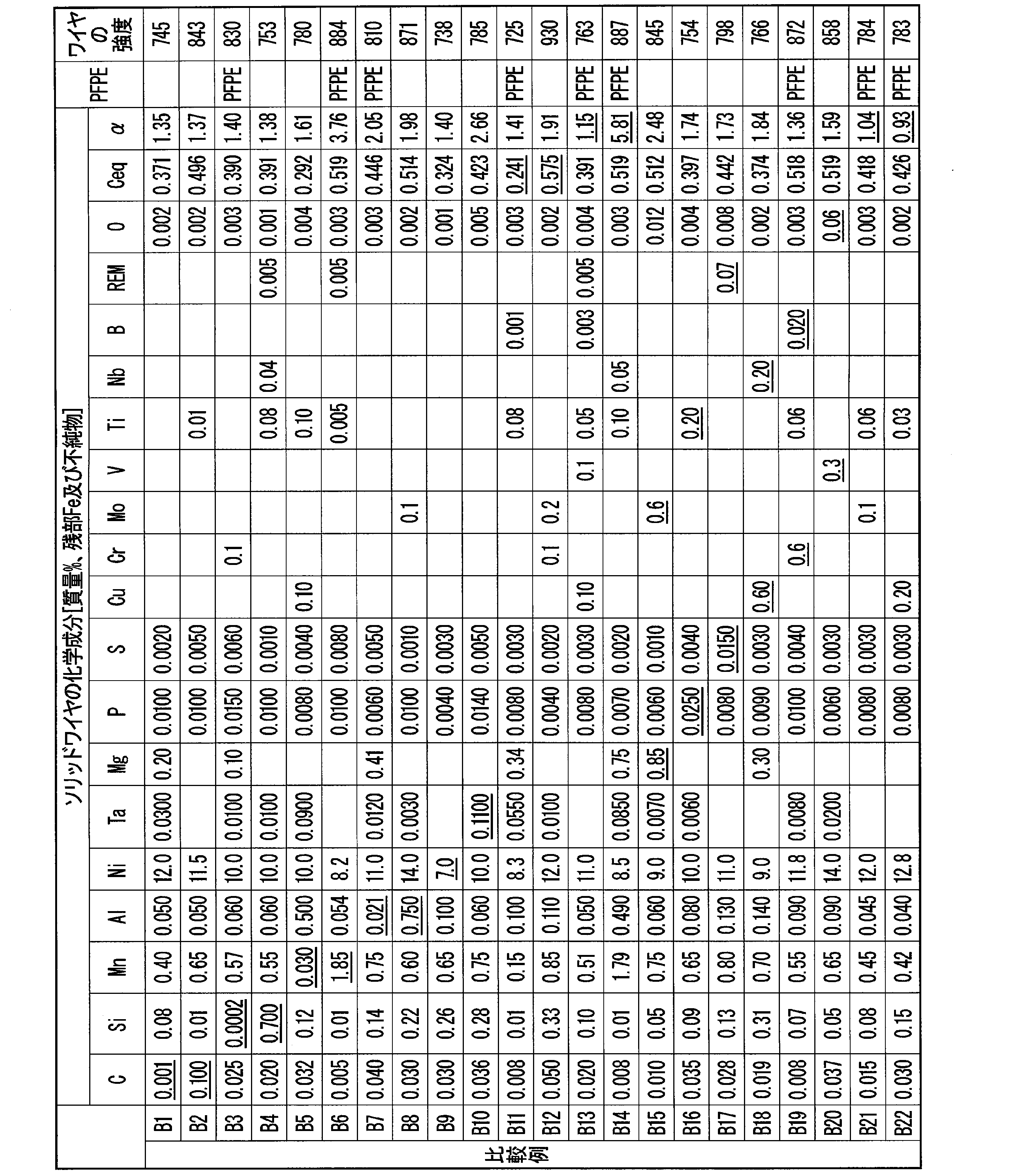
- Solid wires with various chemical compositions were produced. Annealing was applied during the wire drawing work of the solid wire, and the final solid wire diameter was adjusted to ⁇ 1.2 mm. The annealing condition was 650 ° C. for 4 hours. After the trial production, a lubricant was applied to the surface of the solid wire. In Tables 1-1 to 1-2, vegetable oils were applied to all those not described as PFPE oil application. The analysis of the components of the solid wire was carried out by performing chemical analysis, gas analysis, and the like. The analysis was performed without lubricant on the surface of the solid wire. Tables 1-1 to 1-2 show the chemical composition of the prototype solid wire, the presence or absence of PFPE oil coating, and the tensile strength of the solid wire (“wire strength”).
- the mechanical properties of the weld metal were evaluated in accordance with JIS Z 3111: 2005 using the solid wires shown in Tables 1-1 to 1-2. That is, the procedure is as shown in FIG. A steel plate 1 having a plate thickness of 20 mm was butted against each other with a root gap of 16 mm and a groove angle of 20 °, and a backing metal 2 was used. SM490A was used for the steel plate 1 and the backing metal 2, but two or more layers and an extra height of 3 mm or more were used on the groove surface of the steel plate 1 and the surface of the backing metal 2 using the solid wire to be tested. Buttering was carried out.
- welding conditions are shown in Tables 2 and 4 (the composition of the shield gas is expressed in% by volume).
- Table 2 shows MAG welding
- Table 4 shows the welding conditions for MIG welding. From Table 2, the welding conditions are a current value of 280 A, a voltage value of 24-28 V, a welding speed of 30 cm / min, a pass-to-pass temperature of 150 ° C. or less, and a gas using a mixed gas of Ar and 15% by volume CO 2 as a shield gas.
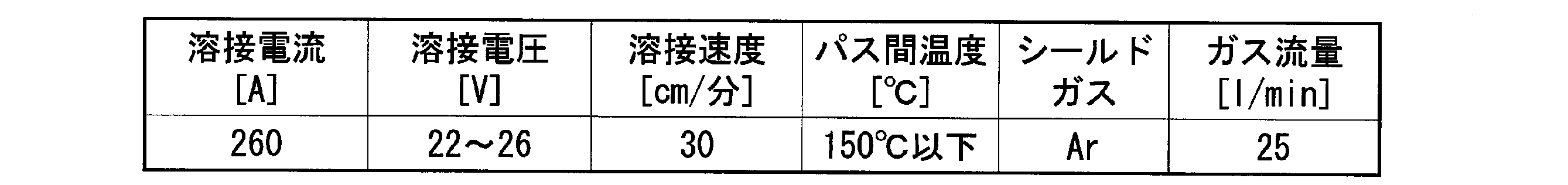
- the flow rate was 25 l / min.
- the welding conditions were a current value of 260 A, a voltage value of 22 to 26 V, a welding speed of 30 cm / min, a pass-to-pass temperature of 150 ° C. or less, and Ar gas as a shield gas at a gas flow rate of 25 l / min.
- the welding defect resistance of each solid wire was evaluated. This is the rate of occurrence of pore defects (welding defect length relative to the welding length) when a downward 1-pass welding bead is produced under the welding conditions shown in Table 2 for low-temperature steel with a plate thickness of 25 mm shown in Table 6. It is an evaluation of the consistency of the weld bead and the ratio).
- a sample having a welding defect length of 5% or less and no bead shape defect or high temperature cracking due to excessive sputtering was accepted, and "None" was described in the table.
- the portion where the largest meandering occurs in the bead formed by the above welding is visually identified, and as shown in FIG.
- the toe of the welding bead when the welding bead meanders.
- the distance (length b) of the toe of the normal weld bead was 25% or less of the bead width (length a)
- the value obtained by b / a ⁇ 100 is referred to as a weld bead matching rate.
- arc stability if the total arc extinguishing time is 10% or less of the total arc generation time (that is, the "arc duration" in Tables 3-1 and 3-2 is more than 90%), it is considered acceptable. did.
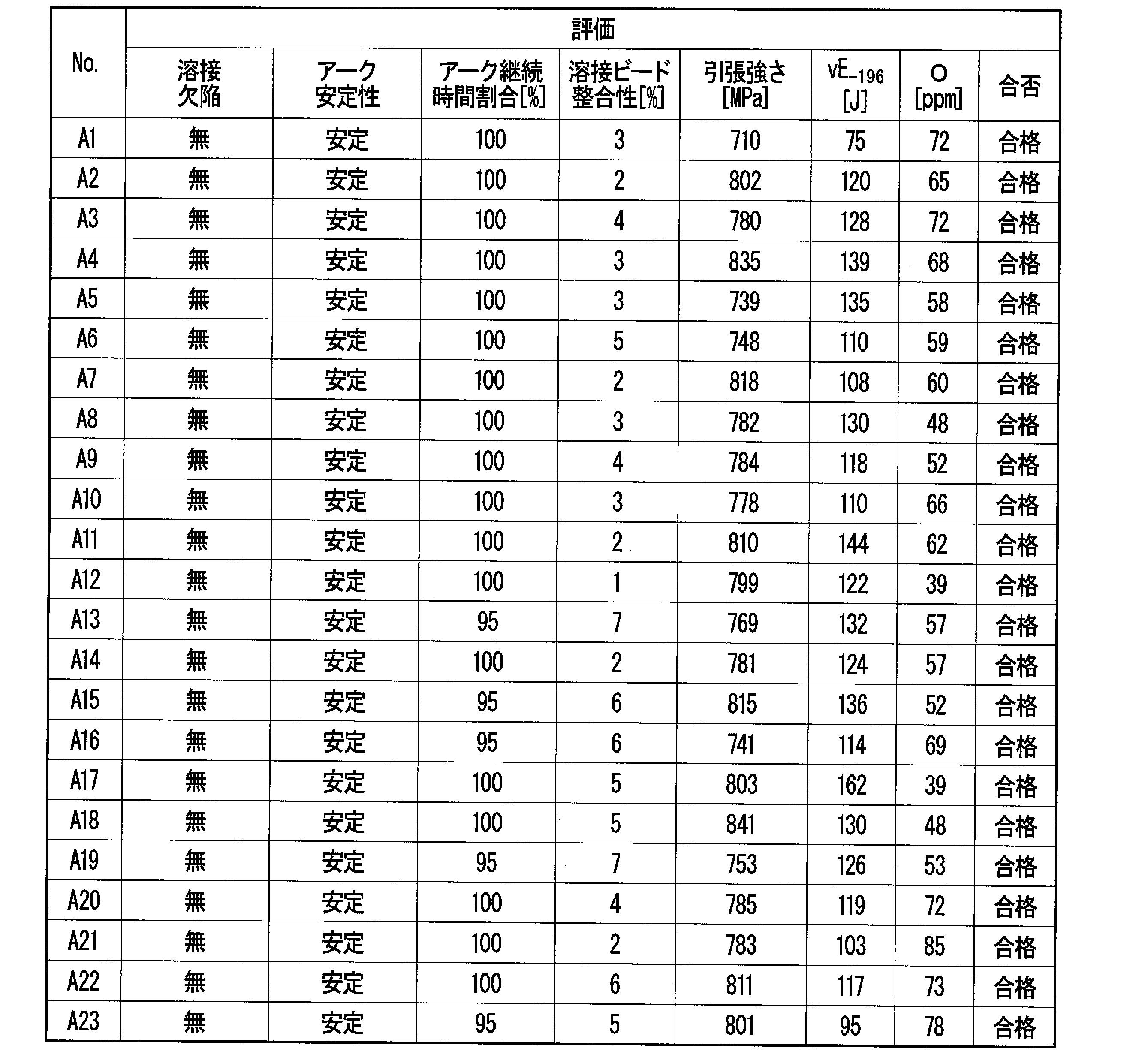
- the solid wire numbers A1 to A23 of the present invention example have tensile strength, toughness, weld defect resistance, arc stability, and weld bead matching. All of the sex was excellent and passed.
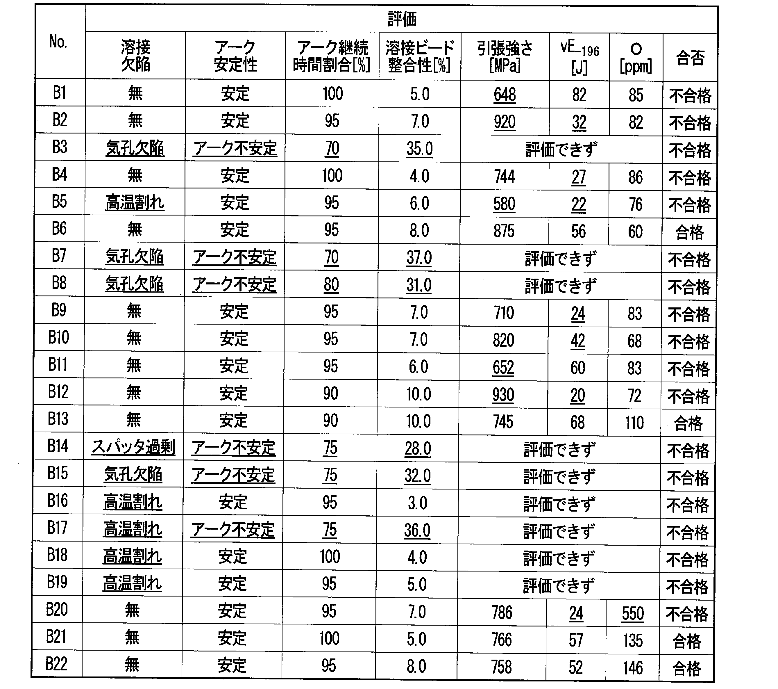
- the solid wire numbers B1 to B22 which are comparative examples, do not meet the requirements specified in the present invention, and therefore have tensile strength and toughness. One or more of the welding defect resistance, arc stability, and welding bead consistency were not satisfied, and the overall judgment was rejected.
- the solid wire according to this embodiment can significantly reduce the welding material cost by reducing the amount of Ni. Further, the solid wire according to the present embodiment can be applied to gas shielded arc welding (for example, MIG welding, MAG welding, etc.) having excellent welding efficiency. Further, the solid wire according to the present embodiment contains a deoxidizing element and a trace element to reduce the amount of oxygen in the welding metal, thereby obtaining a welding metal having excellent low temperature toughness at -196 ° C. The solid wire according to this embodiment can exert a remarkable effect on the prior art when used for welding a Ni-based low temperature steel containing about 5.5 to 9.5% of Ni, for example. it can. Therefore, the value of the solid wire according to the present embodiment in the industry is extremely high.
- gas shielded arc welding for example, MIG welding, MAG welding, etc.
Abstract
Description
α=2×[Mn]+[Al]+1.5×[Ti]+[Mg]+10×[Ta]・・・(式a)
Ceq=[C]+[Si]/24+[Mn]/6+[Ni]/40+[Cr]/5+[Mo]/4+[V]/14・・・(式b)
但し、式aおよび式bの[]付元素は、それぞれの元素の前記ソリッドワイヤの前記全質量に対する質量%での含有量を表す。
(2)上記(1)に記載のソリッドワイヤでは、前記化学組成が、前記ソリッドワイヤの全質量に対する質量%で、Ta:0.0005%以上0.1000%以下;Cu:0.1%以上0.5%以下;Cr:0.01%以上0.5%以下;Mo:0.01%以上0.5%以下;V:0.01%以上0.20%以下;Ti:0.005%以上0.10%以下;Nb:0.002%以上0.10%以下;B:0.0003%以上0.010%以下;Mg:0.10%以上0.80%以下;及びREM:0.001%以上0.050%以下からなる群から選択される一種以上を含有してもよい。
(3)上記(1)又は(2)に記載のソリッドワイヤでは、前記ソリッドワイヤ中の前記REMの含有量が、前記ソリッドワイヤの前記全質量に対する質量%で0.010%以下であってもよい。
(4)上記(1)~(3)のいずれか一項に記載のソリッドワイヤでは、表面にパーフルオロポリエーテル油を有してもよい。
(5)上記(1)~(4)のいずれか一項に記載のソリッドワイヤでは、引張強さが500MPa以上1000MPa以下であってもよい。
(6)本発明の別の態様に係る溶接継手の製造方法は、上記(1)~(5)のいずれか1項に記載のソリッドワイヤを用いて鋼材を溶接する。
(7)上記(6)に記載の溶接継手の製造方法では、前記鋼材が、板厚が6mm以上100mm以下であり、Niの含有量が5.5質量%以上9.5質量%以下であり、引張強さが660MPa以上900MPa以下であってもよい。
(8)上記(6)又は(7)に記載の溶接継手の製造方法では、前記溶接がガスシールドアーク溶接であってもよい。
(9)上記(8)に記載の溶接継手の製造方法では、シールドガスが、純Arガス、純Heガス、Arと合計20体積%以下のO2及びCO2の一方又は両方とを含むガス、並びにHeと合計20体積%以下のO2及びCO2の一方又は両方とを含むガスのいずれかであってもよい。
(i)値αを用いてMn、Al、Ti、及びMg、並びにTaの含有量を最適化すれば、Arと活性ガスの混合ガスを用いたガスシールドアーク溶接によっても、溶接金属の酸素量を大幅に低減できる。
(ii)上記(i)に加えて、C、Si、Mn、Ni、Cr、Mo、Vの含有量を特定の範囲とすることで、-196℃での優れた低温靭性が得られる。
(iii)上記(i)及び(ii)の要件が満たされたソリッドワイヤによれば、ガスシールドアーク溶接を使用可能であるので、溶接施工効率がTIG溶接に比して向上する。
α=2×[Mn]+[Al]+1.5×[Ti]+[Mg]+10×[Ta]・・・(式a)
先ず、本実施形態のソリッドワイヤに含有される合金成分、金属脱酸成分および各成分の含有量の限定理由について説明する。
以下のソリッドワイヤの化学組成の説明において、「%」は特に説明がない限り、「質量%」を意味する。なお、本実施形態に係るソリッドワイヤは、その表面にめっき層を備えてもよい。この場合、ソリッドワイヤの合金成分の分布は一様ではないが、ソリッドワイヤの合金成分は、ソリッドワイヤ全体での平均値として把握される。即ち、以下に説明される各合金成分の含有量は、ソリッドワイヤ全質量に対する各成分の質量%の合計となる成分含有量を意味するものとする。
Cは、溶接金属の強度を向上させる元素である。溶接金属の強度を確保するためには、ソリッドワイヤにCを0.003%以上含有させる必要がある。溶接金属の強度の向上のために、ソリッドワイヤのC含有量の下限を0.005%、0.008%、0.010%、又は0.013%としてもよい。一方で、8~16%のNiを含有する溶接金属は、硬いマルテンサイト組織となる。マルテンサイトの硬さに及ぼすCの影響は非常に大きく、ソリッドワイヤのC含有量が0.080%を超えると、溶接金属が極めて硬化し、靭性が大きく低下する。そのため、ソリッドワイヤのC含有量の上限を0.080%とする。安定して溶接金属の靭性を確保するためには、ソリッドワイヤのC含有量の上限を0.075%、0.070%、0.065%、0.060%、0.055%、又は、0.050%としてもよい。
Siは、溶接金属の清浄度を向上し、ブローホールなどの溶接欠陥の発生を抑制するのに必要な元素である。これらの効果を得るには、ソリッドワイヤが0.0010%以上のSiを含有する必要がある。溶接欠陥の発生を一層防止するために、ソリッドワイヤのSi含有量の下限を0.0050%又は0.0100%としてもよい。一方で、8~16%のNiを含有する溶接金属では、Siはミクロ偏析しやすく、ソリッドワイヤのSi含有量が0.50%を超えると、偏析部で顕著な脆化が生じる。そのため、0.50%をソリッドワイヤのSi含有量の上限とする。また、溶接金属の靭性を安定して確保するためには、ソリッドワイヤのSi含有量の上限を0.40%、又は0.30%としてもよい。
Mnは、脱酸元素であり、さらに溶接金属の清浄度を向上させる。さらにMnは、溶接金属中においてMnSを形成することで、Sによる高温割れの発生を抑制し、溶接金属の靭性を向上させるのに必要な元素である。その効果を得るためには、0.050%以上のMnをソリッドワイヤに含有させる必要がある。溶接金属の靭性の一層の向上のために、ソリッドワイヤのMn含有量の下限を0.100%、0.120%、0.200%又は0.300%としてもよい。一方、8~16%のNiを含有する溶接金属では、Mnはミクロ偏析しやすく、ソリッドワイヤのMn含有量が1.80%を超えると、偏析部で顕著な脆化が生じる。このため、1.80%をソリッドワイヤのMn含有量の上限とする。また、溶接金属の靭性を安定して確保するためには、ソリッドワイヤのMn含有量の上限を1.60%、1.40%、又は1.20%としてもよい。
Alは脱酸元素であり、Si及びMnと同様に、ブローホールなどの溶接欠陥の発生の抑制、及び清浄度向上等に効果がある。その効果を発揮するために0.030%以上のAlをソリッドワイヤに含有させる。一方、0.500%を超えてソリッドワイヤにAlを含有させると、Alが窒化物や酸化物を形成して、溶接金属の靱性を阻害する。そのため、0.500%をソリッドワイヤのAl含有量の上限とする。また、溶接金属の靭性を向上する効果を十分に得るためには、ソリッドワイヤのAl含有量の下限を0.031%、0.033%、0.035%、0.040%、0.045%、0.050%、0.051%、0.053%、または0.055%としてもよい。また、酸化物の生成抑制のため、ソリッドワイヤのAl含有量の上限を、0.480%、0.450%、0.400%、0.350%、0.300%、又は0.200%としてもよい。
Niは、固溶靱化(固溶により靭性を高める作用)により、溶接金属の組織及び成分によらず、溶接金属の靱性を向上できる唯一の元素である。特に、-196℃の低温靭性を確保するために、Niは必須の元素である。この効果を得るためには、ソリッドワイヤのNi含有量は8.0%以上にする必要がある。一方、ソリッドワイヤのNi含有量が16.0%を超えると、その効果が飽和するのに加え、溶接材料コストが過大となるため好ましくない。さらに、ソリッドワイヤのNi含有量が16.0%を超える場合、高温割れが発生しやすく、溶融金属の湯流れが悪く、融合不良などの溶接欠陥が発生しやすくなるので、ソリッドワイヤをガスシールドアーク溶接などの高効率溶接に適用することが困難となる。従って、ソリッドワイヤのNi含有量の上限値を16.0%とする。ソリッドワイヤのNi含有量の上限を15.5%、15.0%、又は14.5%に制限してもよい。安定して溶接金属の低温靭性を確保するためには、ソリッドワイヤのNi含有量の下限を8.5%、9.0%又は、9.5%、更には、10.0%としてもよい。
Pは不純物元素であり、過剰添加は高温割れを発生させる傾向にあり、溶接金属の靱性を劣化させるので、極力低減することが好ましい。溶接金属の靭性への悪影響が許容できる範囲として、ソリッドワイヤのP含有量は0.0200%以下とする。溶接金属の靭性の一層の向上のために、ソリッドワイヤのP含有量の上限を0.0150%、0.0100%、0.0080%又は0.0060%としてもよい。溶接金属の靭性確保の観点からは、ソリッドワイヤのP含有量の下限を制限する必要はなく、P含有量の下限は0%である。一方、精錬コストの低減の観点から、ソリッドワイヤのP含有量の下限を0.0010%、0.0020%、又は0.0030%としてもよい。
Sは、不純物元素であり、過剰添加は高温割れを発生させる傾向にあり、溶接金属の靱性を著しく劣化させるので、極力低減することが好ましい。溶接金属の靱性への悪影響が許容できる範囲として、ソリッドワイヤのS含有量は0.0100%以下とする。溶接金属の靭性の一層の向上のために、ソリッドワイヤのS含有量の上限を0.0080%、0.0060%、0.0040%又は0.0030%としてもよい。溶接金属の靭性確保の観点からは、ソリッドワイヤのS含有量の下限を制限する必要はなく、S含有量の下限は0%である。一方、精錬コストの低減の観点から、ソリッドワイヤのS含有量の下限を0.0005%、0.0010%、又は0.0020%としてもよい。
Oは、不純物であり、溶接金属の靱性を著しく劣化させるので、極力低減することが好ましい。溶接金属の靱性への悪影響が許容できる範囲として、ソリッドワイヤのO含有量は0.050%以下とする。溶接金属の靭性の一層の向上のために、ソリッドワイヤのO含有量の上限を0.020%、0.015%、0.010%又は0.005%としてもよい。溶接金属の靭性確保の観点からは、ソリッドワイヤのO含有量の下限を制限する必要はなく、O含有量の下限は0%である。一方、精錬コストの低減の観点から、ソリッドワイヤのO含有量の下限を0.0005%、0.001%、又は0.002%としてもよい。
Taは析出強化元素であり、溶接金属の強度を向上させる効果がある。さらにTaは、高温アーク中に存在する酸素と結合して、溶接金属中の酸素含有量を低減できる元素である。一方で、ソリッドワイヤのTa含有量が0.1000%を超える場合、溶接金属中の酸素量が一定となり、これ以上低減しにくくなる一方で、溶接金属の強度が過剰となり、溶接金属の低温靭性を阻害する。そのため、ソリッドワイヤのTa含有量の上限を0.1000%とする。溶接金属の高強度化および酸素量低減の効果を十分に得るためには、ソリッドワイヤのTa含有量の下限を0.0005%、0.0010%、0.0015%、0.0020%、0.0025%、又は0.0030%としてもよい。また、溶接金属の低温靭性を一層向上させるためには、ソリッドワイヤのTa含有量の上限値を0.090%、0.080%、0.070%、0.060%、又は0.050%としてもよい。
Cuは、ソリッドワイヤの表面のめっきとして、単体または合金としてソリッドワイヤに含有された場合には、固溶強化により、溶接金属の強度を向上させる効果がある。また、Cuがソリッドワイヤ中に単体または合金として含有された場合にも、同様の効果が得られる。ソリッドワイヤのCu含有量の下限は0%とするが、ソリッドワイヤがCuを含有してもよい。例えば、Cu含有の効果を得るためには、ソリッドワイヤのCu含有量の下限を0.1%、としてもよい。一方、ソリッドワイヤのCu含有量が0.5%を超えると溶接金属の靭性が低下する。そのため、ソリッドワイヤのCu含有量は0.5%以下とする。溶接金属の靭性の向上のために、ソリッドワイヤのCu含有量の上限を0.3%、又は0.2%としてもよい。
Crは、溶接金属の強度を高めるのに有効な元素である。ソリッドワイヤのCrの含有量の下限は0%とするが、含有の効果を得るために、ソリッドワイヤのCr含有量の下限を0.01%としてもよい。一方、Crをソリッドワイヤに含有させる場合、ソリッドワイヤのCr含有量が0.5%を超えると溶接金属の靭性が低下する。そのため、ソリッドワイヤのCr含有量は0.5%以下とする。溶接金属の靭性の一層の向上のために、ソリッドワイヤのCr含有量の上限を0.3%、0.2%又は0.1%としてもよい。
Moは、析出強化により溶接金属の強度を高めるのに有効な元素である。ソリッドワイヤのMoの含有量の下限は0%とするが、Mo含有の効果を得るために、ソリッドワイヤのMo含有量の下限を0.01%としてもよい。Moをソリッドワイヤに含有させる場合、ソリッドワイヤのMo含有量が0.5%を超えると溶接金属の靭性が低下する。そのため、ソリッドワイヤのMo含有量は0.5%以下とする。溶接金属の靭性の一層の向上のために、ソリッドワイヤのMo含有量の上限を0.3%、0.2%又は0.1%としてもよい。
Vは、析出強化により溶接金属の強度を高めるのに有効な元素である。ソリッドワイヤのVの含有量の下限は0%とするが、V含有の効果を得るために、ソリッドワイヤのV含有量の下限を0.01%としてもよい。Vをソリッドワイヤに含有させる場合、ソリッドワイヤのV含有量が0.20%を超えると溶接金属の靭性が低下する。そのため、Vを含有させる場合のソリッドワイヤのV含有量は0.20%以下とする。溶接金属の靭性の一層の向上のために、ソリッドワイヤのV含有量の上限を0.15%、0.10%又は0.05%としてもよい。
Tiは、固溶Nを固定して、溶接金属の靭性への悪影響を緩和するのに有効である。また、Tiは脱酸元素としても有効であり、溶接金属中の酸素量を低減させる効果がある。ソリッドワイヤのTiの含有量の下限は0%とするが、Ti含有の効果を得るために、ソリッドワイヤのTi含有量の下限を0.005%としてもよい。Tiをソリッドワイヤに含有させる場合、ソリッドワイヤのTi含有量が0.10%を超えて過剰になると、炭化物が生成し、溶接金属の靭性を劣化させる。そのため、Tiを含有させる場合のソリッドワイヤのTi含有量は、0.10%以下とする。溶接金属の靭性の一層の向上のために、ソリッドワイヤのTi含有量の上限を0.06%、0.04%又は0.02%としてもよい。
Nbは析出強化により溶接金属の強度を高めるのに有効である。ソリッドワイヤのNbの含有量の下限は0%とするが、Nb含有の効果を得るために、Nb含有量の下限を0.002%としてもよい。Nbをソリッドワイヤに含有させる場合、ソリッドワイヤのNb含有量が0.10%を超えて過剰になると、溶接金属中に粗大な析出物を形成して溶接金属の靭性を劣化させる。加えて、ソリッドワイヤのNb含有量が0.10%を超えて過剰になると、高温割れが発生する傾向がある。そのため、Nbを含有させる場合のソリッドワイヤのNb含有量は0.10%以下とする。溶接金属の靭性の一層の向上のために、ソリッドワイヤのNb含有量の上限を0.06%、0.04%又は0.02%としてもよい。
Bは、溶接金属中に適正量含有させると、固溶Nと結びついてBNを形成して、固溶Nの靭性に対する悪影響を減じる効果がある。ソリッドワイヤのBの含有量の下限は0%とするが、B含有の効果を得るために、ソリッドワイヤのB含有量の下限を0.0003%としてもよい。Bをソリッドワイヤに含有させる場合、ソリッドワイヤのB含有量が0.010%を超えると、溶接金属中のBが過剰となり、粗大なBNやFe23(C、B)6等のB化合物を形成して溶接金属の靭性を逆に劣化させる。加えて、ソリッドワイヤのB含有量が0.010%を超えると、高温割れが発生する傾向がある。そのため、Bを含有させる場合のソリッドワイヤのB含有量は0.010%以下とする。溶接金属の靭性の一層の向上のために、ソリッドワイヤのB含有量の上限を0.006%、0.004%又は0.002%としてもよい。
Mgは、脱酸元素であり、溶接金属の酸素を低減し、溶接金属の靭性の改善に効果がある。ソリッドワイヤのMgの含有量の下限は0%とするが、溶接金属中の酸素量を低減する効果を十分得るためには、ソリッドワイヤのMg含有量の下限を0.10%、0.15%、0.20%、0.25%、または0.30%としてもよい。一方、ソリッドワイヤのMg含有量が0.80%を超える場合、スパッタが増加し、溶接作業性を劣化させる。そのため、0.80%をソリッドワイヤのMg含有量の上限とする。溶接作業性の一層の向上のために、ソリッドワイヤのMg含有量の上限を0.78%、0.75%、0.73%、0.70%、0.65%又は0.60%としてもよい。
REMは本実施形態に係るソリッドワイヤの課題解決のために必須ではないため、REM含有量の下限は0%とする。しかし、REMは、アークを安定化させる元素であるので、ソリッドワイヤに含有させてもよい。この効果を得るために、ソリッドワイヤのREM含有量の下限を0.001%、0.010%、又は0.020%としてもよい。REMをソリッドワイヤに含有させる場合、スパッタが低減し、アークが安定となる効果的なREM含有量は、0.050%以下である。一方で、ソリッドワイヤが過剰にREMを含有すると、スパッタが激しくなり、溶接作業性が劣悪となる。このため、スパッタの低減およびアークの安定に寄与するために、ソリッドワイヤのREM含有量の上限を0.030%、0.020%、0.010%、0.005%、又は0.001%としてもよい。なお「REM」との用語は、Sc、Yおよびランタノイドからなる合計17元素を指し、上記「REM含有量」とは、これらの17元素の合計含有量を意味する。ランタノイドをREMとして用いる場合、工業的には、REMはミッシュメタルの形で添加される。
本実施形態のソリッドワイヤは、上述の各元素を含有するが、溶接金属の-196℃の低温靭性を確保するためには、さらに下記式aで表されるαが、1.35%以上5.50%以下となるようにその各元素の含有量を制御する必要がある。
α=2×[Mn]+[Al]+1.5×[Ti]+[Mg]+10×[Ta]・・・(式a)
但し、[]付元素は、それぞれの元素の含有量(質量%)を示す。
さらに本実施形態のソリッドワイヤでは、下記式bで表される、日本溶接協会(WES)で定める炭素当量Ceqが0.250%以上0.520%以下となるように、C、Si、Mn、Ni、Cr、Mo、Vの含有量をさらに調整する。
Ceq=[C]+[Si]/24+[Mn]/6+[Ni]/40+[Cr]/5+[Mo]/4+[V]/14・・・(式b)
但し、[]付元素は、それぞれの元素の質量%での含有量を示す。
ソリッドワイヤの径は特に限定されない。現在、市場に流通するソリッドワイヤ及び溶接設備を考慮して、例えば本実施形態に係るソリッドワイヤの径を0.5~2.4mmとしてもよい。ソリッドワイヤの径を0.8mm以上、又は1.0mm以上としてもよい。ソリッドワイヤの径を1.6mm以下、又は1.4mm以下としてもよい。
ソリッドワイヤの機械的性質も特に限定されない。溶接中のソリッドワイヤの送給性を向上させる観点からは、ソリッドワイヤの引張強さが低いことが好ましく、例えばソリッドワイヤの引張強さを950MPa以下、900MPa以下、850MPa、800MPa、750MPa、又は700MPa以下としてもよい。
本開示において、シールドガスとして、ArガスまたはHeガスに、合計20体積%以下のO2及びCO2の一方又は両方を添加したガスを用いる場合、これはMAG溶接に対応する。溶接時のアーク安定性を重視する場合、この形態が好ましい。
試作したソリッドワイヤの化学組成、PFPE油塗布の有無、及びソリッドワイヤの引張強さ(「ワイヤの強度」)を表1-1~表1-2に示す。表1-1~表1-2に示したソリッドワイヤの化学組成は、上記の分析方法により分析した結果である。なお、本発明の範囲外である値には下線を付した。また、検出限界以下である元素の含有量は記入せず、空白で表した。ソリッドワイヤの引張強さの単位はMPaである。
機械特性の評価にあたっては、引張強さが660~900MPaであり、且つ-196℃でのシャルピー衝撃試験で吸収エネルギーが50J以上であるものを、合格とした。
本発明のソリッドワイヤにおいては、溶着金属中の酸素量を低減することで靱性を向上させている。酸素量が160ppm以下としなければ、-196℃でのシャルピー吸収エネルギーを確保することができないことが、発明例及び比較例を通じて確認された。
一方、表3-2および表5-2の試験結果に示されるように、比較例であるソリッドワイヤ番号B1~B22は、本発明で規定する要件を満たしていないため、引張強さ、靭性、耐溶接欠陥性、アーク安定性、及び溶接ビード整合性のうち一項目以上満足できず、総合判定で不合格となった。


2 裏当金
3 溶接ビード
4 シャルピー衝撃試験片(2mmVノッチ)
5 A0号引張り試験片(丸棒)
Claims (9)
- ソリッドワイヤであって、
化学組成が、前記ソリッドワイヤの全質量に対する質量%で:
C:0.003%以上0.080%以下;
Si:0.0010%以上0.50%以下;
Mn:0.050%以上1.80%以下;
Al:0.030%以上0.500%以下;
Ni:8.0%以上16.0%以下;
P:0.0200%以下;
S:0.0100%以下;
O:0.050%以下;
Ta:0%以上0.1000%以下;
Cu:0%以上0.5%以下;
Cr:0%以上0.5%以下;
Mo:0%以上0.5%以下;
V:0%以上0.20%以下;
Ti:0%以上0.10%以下;
Nb:0%以上0.10%以下;
B:0%以上0.010%以下;
Mg:0%以上0.80%以下;
REM:0%以上0.050%以下;及び
残部:Feおよび不純物
からなり、
下記の式aで定義されるαが1.35%以上5.50%以下であり、
下記の式bで定義されるCeqが0.250%以上0.520%以下である
ことを特徴とするソリッドワイヤ。
α=2×[Mn]+[Al]+1.5×[Ti]+[Mg]+10×[Ta]・・・(式a)
Ceq=[C]+[Si]/24+[Mn]/6+[Ni]/40+[Cr]/5+[Mo]/4+[V]/14・・・(式b)
但し、式aおよび式bの[]付元素は、それぞれの元素の前記ソリッドワイヤの前記全質量に対する質量%での含有量を表す。 - 前記化学組成が、前記ソリッドワイヤの全質量に対する質量%で、
Ta:0.0005%以上0.1000%以下;
Cu:0.1%以上0.5%以下;
Cr:0.01%以上0.5%以下;
Mo:0.01%以上0.5%以下;
V:0.01%以上0.20%以下;
Ti:0.005%以上0.10%以下;
Nb:0.002%以上0.10%以下;
B:0.0003%以上0.010%以下;
Mg:0.10%以上0.80%以下;及び
REM:0.001%以上0.050%以下
からなる群から選択される一種以上を含有することを特徴とする請求項1に記載のソリッドワイヤ。 - 前記ソリッドワイヤ中の前記REMの含有量が、前記ソリッドワイヤの前記全質量に対する質量%で0.010%以下であることを特徴とする請求項1又は2に記載のソリッドワイヤ。
- 表面にパーフルオロポリエーテル油を有することを特徴とする請求項1~3のいずれか一項に記載のソリッドワイヤ。
- 引張強さが500MPa以上1000MPa以下であることを特徴とする請求項1~4のいずれか一項に記載のソリッドワイヤ。
- 請求項1~5のいずれか1項に記載のソリッドワイヤを用いて鋼材を溶接することを特徴とする溶接継手の製造方法。
- 前記鋼材が、
板厚が6mm以上100mm以下であり、
Niの含有量が5.5質量%以上9.5質量%以下であり、
引張強さが660MPa以上900MPa以下である
ことを特徴とする請求項6に記載の溶接継手の製造方法。 - 前記溶接がガスシールドアーク溶接であることを特徴とする請求項6又は7に記載の溶接継手の製造方法。
- シールドガスが、純Arガス、純Heガス、Arと合計20体積%以下のO2及びCO2の一方又は両方とを含むガス、並びにHeと合計20体積%以下のO2及びCO2の一方又は両方とを含むガスのいずれかであることを特徴とする請求項8に記載の溶接継手の製造方法。
Priority Applications (6)
| Application Number | Priority Date | Filing Date | Title |
|---|---|---|---|
| CN201980050707.4A CN112512742B (zh) | 2019-04-10 | 2019-04-10 | 实心焊丝以及焊接接头的制造方法 |
| KR1020217003130A KR102480788B1 (ko) | 2019-04-10 | 2019-04-10 | 솔리드 와이어 및 용접 조인트의 제조 방법 |
| EP19923809.8A EP3812085B1 (en) | 2019-04-10 | 2019-04-10 | Solid wire and method of manufacturing welded joint |
| JP2019547171A JP6690786B1 (ja) | 2019-04-10 | 2019-04-10 | ソリッドワイヤ及び溶接継手の製造方法 |
| PCT/JP2019/015595 WO2020208735A1 (ja) | 2019-04-10 | 2019-04-10 | ソリッドワイヤ及び溶接継手の製造方法 |
| US17/261,517 US20210340652A1 (en) | 2019-04-10 | 2019-04-10 | Solid wire and method of manufacturing welded joint |
Applications Claiming Priority (1)
| Application Number | Priority Date | Filing Date | Title |
|---|---|---|---|
| PCT/JP2019/015595 WO2020208735A1 (ja) | 2019-04-10 | 2019-04-10 | ソリッドワイヤ及び溶接継手の製造方法 |
Publications (1)
| Publication Number | Publication Date |
|---|---|
| WO2020208735A1 true WO2020208735A1 (ja) | 2020-10-15 |
Family
ID=70413794
Family Applications (1)
| Application Number | Title | Priority Date | Filing Date |
|---|---|---|---|
| PCT/JP2019/015595 WO2020208735A1 (ja) | 2019-04-10 | 2019-04-10 | ソリッドワイヤ及び溶接継手の製造方法 |
Country Status (6)
| Country | Link |
|---|---|
| US (1) | US20210340652A1 (ja) |
| EP (1) | EP3812085B1 (ja) |
| JP (1) | JP6690786B1 (ja) |
| KR (1) | KR102480788B1 (ja) |
| CN (1) | CN112512742B (ja) |
| WO (1) | WO2020208735A1 (ja) |
Cited By (2)
| Publication number | Priority date | Publication date | Assignee | Title |
|---|---|---|---|---|
| JP7029034B1 (ja) * | 2020-11-26 | 2022-03-02 | Jfeスチール株式会社 | 溶接継手およびその製造方法 |
| WO2022113473A1 (ja) * | 2020-11-26 | 2022-06-02 | Jfeスチール株式会社 | 溶接継手およびその製造方法 |
Families Citing this family (1)
| Publication number | Priority date | Publication date | Assignee | Title |
|---|---|---|---|---|
| CN113798721B (zh) * | 2021-07-21 | 2022-07-08 | 中国船舶重工集团公司第七二五研究所 | 一种屈服强度超过890MPa的金红石型药芯焊丝 |
Citations (7)
| Publication number | Priority date | Publication date | Assignee | Title |
|---|---|---|---|---|
| JPS5476452A (en) * | 1977-11-30 | 1979-06-19 | Kobe Steel Ltd | Wire for tig welding and tig welding method |
| JPH09253860A (ja) | 1996-03-22 | 1997-09-30 | Kobe Steel Ltd | 高張力鋼のtig溶接方法及びtig溶接用ソリッドワイヤ |
| JP2008161932A (ja) | 2006-09-06 | 2008-07-17 | L'air Liquide-Sa Pour L'etude & L'exploitation Des Procedes Georges Claude | ワイヤ、フラックス及び高ニッケル含量を有している鋼を溶接するためのプロセス |
| JP2008246507A (ja) | 2007-03-29 | 2008-10-16 | Kobe Steel Ltd | Ni基合金フラックス入りワイヤ |
| JP2009101414A (ja) * | 2007-10-05 | 2009-05-14 | Kobe Steel Ltd | 溶接用ソリッドワイヤ |
| WO2012086042A1 (ja) * | 2010-12-22 | 2012-06-28 | 株式会社神戸製鋼所 | 溶接ソリッドワイヤおよび溶接金属 |
| JP2015110247A (ja) * | 2013-11-08 | 2015-06-18 | 新日鐵住金株式会社 | ガスシールドアーク溶接用フラックス入りワイヤ及び極低温用鋼の溶接方法ならびに溶接継手の製造方法 |
Family Cites Families (9)
| Publication number | Priority date | Publication date | Assignee | Title |
|---|---|---|---|---|
| JP5019781B2 (ja) * | 2006-04-27 | 2012-09-05 | 株式会社神戸製鋼所 | ガスシールドアーク溶接フラックス入りワイヤを使用するmigアーク溶接方法 |
| WO2009044808A1 (ja) * | 2007-10-05 | 2009-04-09 | Kabushiki Kaisha Kobe Seiko Sho | 溶接用ソリッドワイヤ |
| JP5244059B2 (ja) * | 2009-09-09 | 2013-07-24 | 株式会社神戸製鋼所 | 溶接ソリッドワイヤおよび溶接金属 |
| JP5440744B1 (ja) * | 2012-05-08 | 2014-03-12 | 新日鐵住金株式会社 | 超高張力鋼溶接用フラックス入りワイヤ |
| EP2952288B1 (en) * | 2013-01-31 | 2018-09-05 | Nippon Steel & Sumitomo Metal Corporation | Flux cored wire, welding method using flux cored wire, method for producing welded joint using flux cored wire, and welded joint |
| JP6063355B2 (ja) * | 2013-06-27 | 2017-01-18 | 株式会社神戸製鋼所 | 溶接用ソリッドワイヤおよび溶接方法 |
| WO2015068273A1 (ja) * | 2013-11-08 | 2015-05-14 | 新日鐵住金株式会社 | ガスシールドアーク溶接用フラックス入りワイヤ及びそのワイヤを用いた極低温用鋼の溶接方法 |
| US9770789B2 (en) * | 2013-11-08 | 2017-09-26 | Nippon Steel & Sumitomo Metal Corporation | Flux-cored wire for gas-shielded arc welding, method for welding steel for very low temperature use, and method for manufacturing weld joint |
| JP6801494B2 (ja) * | 2017-02-16 | 2020-12-16 | 日本製鉄株式会社 | ガスシールドアーク溶接用フラックス入りワイヤ、および溶接継手の製造方法 |
-
2019
- 2019-04-10 CN CN201980050707.4A patent/CN112512742B/zh active Active
- 2019-04-10 JP JP2019547171A patent/JP6690786B1/ja active Active
- 2019-04-10 EP EP19923809.8A patent/EP3812085B1/en active Active
- 2019-04-10 WO PCT/JP2019/015595 patent/WO2020208735A1/ja unknown
- 2019-04-10 US US17/261,517 patent/US20210340652A1/en active Pending
- 2019-04-10 KR KR1020217003130A patent/KR102480788B1/ko active IP Right Grant
Patent Citations (7)
| Publication number | Priority date | Publication date | Assignee | Title |
|---|---|---|---|---|
| JPS5476452A (en) * | 1977-11-30 | 1979-06-19 | Kobe Steel Ltd | Wire for tig welding and tig welding method |
| JPH09253860A (ja) | 1996-03-22 | 1997-09-30 | Kobe Steel Ltd | 高張力鋼のtig溶接方法及びtig溶接用ソリッドワイヤ |
| JP2008161932A (ja) | 2006-09-06 | 2008-07-17 | L'air Liquide-Sa Pour L'etude & L'exploitation Des Procedes Georges Claude | ワイヤ、フラックス及び高ニッケル含量を有している鋼を溶接するためのプロセス |
| JP2008246507A (ja) | 2007-03-29 | 2008-10-16 | Kobe Steel Ltd | Ni基合金フラックス入りワイヤ |
| JP2009101414A (ja) * | 2007-10-05 | 2009-05-14 | Kobe Steel Ltd | 溶接用ソリッドワイヤ |
| WO2012086042A1 (ja) * | 2010-12-22 | 2012-06-28 | 株式会社神戸製鋼所 | 溶接ソリッドワイヤおよび溶接金属 |
| JP2015110247A (ja) * | 2013-11-08 | 2015-06-18 | 新日鐵住金株式会社 | ガスシールドアーク溶接用フラックス入りワイヤ及び極低温用鋼の溶接方法ならびに溶接継手の製造方法 |
Non-Patent Citations (2)
| Title |
|---|
| KAZUO AGUSAMASAAKI KOSHO ET AL.: "Matching Ferritic Filler MIG Welding of 9% Ni Steel", KAWASAKI STEEL G1HO, vol. 14, 1982 |
| See also references of EP3812085A4 |
Cited By (2)
| Publication number | Priority date | Publication date | Assignee | Title |
|---|---|---|---|---|
| JP7029034B1 (ja) * | 2020-11-26 | 2022-03-02 | Jfeスチール株式会社 | 溶接継手およびその製造方法 |
| WO2022113473A1 (ja) * | 2020-11-26 | 2022-06-02 | Jfeスチール株式会社 | 溶接継手およびその製造方法 |
Also Published As
| Publication number | Publication date |
|---|---|
| CN112512742B (zh) | 2022-03-29 |
| KR102480788B1 (ko) | 2022-12-23 |
| EP3812085A1 (en) | 2021-04-28 |
| EP3812085A4 (en) | 2022-03-23 |
| CN112512742A (zh) | 2021-03-16 |
| JP6690786B1 (ja) | 2020-04-28 |
| KR20210031474A (ko) | 2021-03-19 |
| US20210340652A1 (en) | 2021-11-04 |
| EP3812085B1 (en) | 2024-04-03 |
| JPWO2020208735A1 (ja) | 2021-05-06 |
Similar Documents
| Publication | Publication Date | Title |
|---|---|---|
| KR101674743B1 (ko) | 가스 실드 아크 용접용 플럭스 내장 와이어 및 극저온용 강의 용접 방법 및 용접 조인트의 제조 방법 | |
| JP5005309B2 (ja) | 高張力鋼用ガスシールドアーク溶接フラックス入りワイヤ | |
| JP6978613B2 (ja) | 極低温用高強度溶接継手の製造方法 | |
| WO2020039643A1 (ja) | ガスメタルアーク溶接用ソリッドワイヤ | |
| JP6953869B2 (ja) | ガスシールドアーク溶接用フラックス入りワイヤ、及び溶接継手の製造方法 | |
| KR20170140798A (ko) | 가스 실드 아크 용접용 플럭스 내장 와이어 | |
| JP6978615B2 (ja) | Tig溶接用溶加材 | |
| JP6690786B1 (ja) | ソリッドワイヤ及び溶接継手の製造方法 | |
| JPWO2020039643A1 (ja) | ガスメタルアーク溶接用ソリッドワイヤ | |
| JP6063355B2 (ja) | 溶接用ソリッドワイヤおよび溶接方法 | |
| JP5244059B2 (ja) | 溶接ソリッドワイヤおよび溶接金属 | |
| JP6155810B2 (ja) | ガスシールドアーク溶接用高Niフラックス入りワイヤ | |
| JP6801494B2 (ja) | ガスシールドアーク溶接用フラックス入りワイヤ、および溶接継手の製造方法 | |
| JP6235402B2 (ja) | 強度、靭性および耐sr割れ性に優れた溶接金属 | |
| JP7024931B1 (ja) | ガスメタルアーク溶接用ソリッドワイヤ | |
| JP2018192518A (ja) | ガスシールドアーク溶接用フラックス入りワイヤ、及び溶接継手の製造方法 | |
| JP6953870B2 (ja) | ガスシールドアーク溶接用フラックス入りワイヤ、及び溶接継手の製造方法 | |
| KR20190037286A (ko) | 가스 실드 아크 용접용 플럭스 코어드 와이어 및 용접 금속 | |
| JP2019048323A (ja) | ガスシールドアーク溶接用フラックス入りワイヤ、及び溶接継手の製造方法 | |
| JP2017164768A (ja) | ガスシールドアーク溶接用高Niフラックス入りワイヤ及び溶接継手の製造方法 | |
| WO2022131333A1 (ja) | Tig溶接用溶加材およびそれを用いた溶接継手部の製造方法 | |
| US20230271277A1 (en) | Flux-cored wire | |
| JP2022061826A (ja) | 溶接継手の製造方法及び開先充填用のフラックス入りカットワイヤ | |
| WO2024069986A1 (ja) | 溶接金属、溶接継手、及び溶接構造物 | |
| JP2022061819A (ja) | 溶接継手の製造方法及び開先充填用のフラックス入りカットワイヤ |
Legal Events
| Date | Code | Title | Description |
|---|---|---|---|
| ENP | Entry into the national phase |
Ref document number: 2019547171 Country of ref document: JP Kind code of ref document: A |
|
| 121 | Ep: the epo has been informed by wipo that ep was designated in this application |
Ref document number: 19923809 Country of ref document: EP Kind code of ref document: A1 |
|
| ENP | Entry into the national phase |
Ref document number: 2019923809 Country of ref document: EP Effective date: 20210119 Ref document number: 20217003130 Country of ref document: KR Kind code of ref document: A |
|
| NENP | Non-entry into the national phase |
Ref country code: DE |