WO2020202708A1 - 全固体リチウムイオン電池用正極活物質、電極及び全固体リチウムイオン電池 - Google Patents
全固体リチウムイオン電池用正極活物質、電極及び全固体リチウムイオン電池 Download PDFInfo
- Publication number
- WO2020202708A1 WO2020202708A1 PCT/JP2020/001480 JP2020001480W WO2020202708A1 WO 2020202708 A1 WO2020202708 A1 WO 2020202708A1 JP 2020001480 W JP2020001480 W JP 2020001480W WO 2020202708 A1 WO2020202708 A1 WO 2020202708A1
- Authority
- WO
- WIPO (PCT)
- Prior art keywords
- positive electrode
- active material
- electrode active
- solid
- lithium
- Prior art date
Links
Images


Classifications
-
- H—ELECTRICITY
- H01—ELECTRIC ELEMENTS
- H01M—PROCESSES OR MEANS, e.g. BATTERIES, FOR THE DIRECT CONVERSION OF CHEMICAL ENERGY INTO ELECTRICAL ENERGY
- H01M4/00—Electrodes
- H01M4/02—Electrodes composed of, or comprising, active material
- H01M4/36—Selection of substances as active materials, active masses, active liquids
- H01M4/362—Composites
- H01M4/366—Composites as layered products
-
- C—CHEMISTRY; METALLURGY
- C01—INORGANIC CHEMISTRY
- C01G—COMPOUNDS CONTAINING METALS NOT COVERED BY SUBCLASSES C01D OR C01F
- C01G53/00—Compounds of nickel
- C01G53/40—Nickelates
- C01G53/42—Nickelates containing alkali metals, e.g. LiNiO2
- C01G53/44—Nickelates containing alkali metals, e.g. LiNiO2 containing manganese
- C01G53/50—Nickelates containing alkali metals, e.g. LiNiO2 containing manganese of the type [MnO2]n-, e.g. Li(NixMn1-x)O2, Li(MyNixMn1-x-y)O2
-
- H—ELECTRICITY
- H01—ELECTRIC ELEMENTS
- H01M—PROCESSES OR MEANS, e.g. BATTERIES, FOR THE DIRECT CONVERSION OF CHEMICAL ENERGY INTO ELECTRICAL ENERGY
- H01M10/00—Secondary cells; Manufacture thereof
- H01M10/05—Accumulators with non-aqueous electrolyte
- H01M10/052—Li-accumulators
-
- H—ELECTRICITY
- H01—ELECTRIC ELEMENTS
- H01M—PROCESSES OR MEANS, e.g. BATTERIES, FOR THE DIRECT CONVERSION OF CHEMICAL ENERGY INTO ELECTRICAL ENERGY
- H01M10/00—Secondary cells; Manufacture thereof
- H01M10/05—Accumulators with non-aqueous electrolyte
- H01M10/056—Accumulators with non-aqueous electrolyte characterised by the materials used as electrolytes, e.g. mixed inorganic/organic electrolytes
- H01M10/0561—Accumulators with non-aqueous electrolyte characterised by the materials used as electrolytes, e.g. mixed inorganic/organic electrolytes the electrolyte being constituted of inorganic materials only
- H01M10/0562—Solid materials
-
- H—ELECTRICITY
- H01—ELECTRIC ELEMENTS
- H01M—PROCESSES OR MEANS, e.g. BATTERIES, FOR THE DIRECT CONVERSION OF CHEMICAL ENERGY INTO ELECTRICAL ENERGY
- H01M10/00—Secondary cells; Manufacture thereof
- H01M10/05—Accumulators with non-aqueous electrolyte
- H01M10/056—Accumulators with non-aqueous electrolyte characterised by the materials used as electrolytes, e.g. mixed inorganic/organic electrolytes
- H01M10/0564—Accumulators with non-aqueous electrolyte characterised by the materials used as electrolytes, e.g. mixed inorganic/organic electrolytes the electrolyte being constituted of organic materials only
- H01M10/0565—Polymeric materials, e.g. gel-type or solid-type
-
- H—ELECTRICITY
- H01—ELECTRIC ELEMENTS
- H01M—PROCESSES OR MEANS, e.g. BATTERIES, FOR THE DIRECT CONVERSION OF CHEMICAL ENERGY INTO ELECTRICAL ENERGY
- H01M4/00—Electrodes
- H01M4/02—Electrodes composed of, or comprising, active material
- H01M4/13—Electrodes for accumulators with non-aqueous electrolyte, e.g. for lithium-accumulators; Processes of manufacture thereof
- H01M4/131—Electrodes based on mixed oxides or hydroxides, or on mixtures of oxides or hydroxides, e.g. LiCoOx
-
- H—ELECTRICITY
- H01—ELECTRIC ELEMENTS
- H01M—PROCESSES OR MEANS, e.g. BATTERIES, FOR THE DIRECT CONVERSION OF CHEMICAL ENERGY INTO ELECTRICAL ENERGY
- H01M4/00—Electrodes
- H01M4/02—Electrodes composed of, or comprising, active material
- H01M4/36—Selection of substances as active materials, active masses, active liquids
- H01M4/48—Selection of substances as active materials, active masses, active liquids of inorganic oxides or hydroxides
- H01M4/50—Selection of substances as active materials, active masses, active liquids of inorganic oxides or hydroxides of manganese
- H01M4/505—Selection of substances as active materials, active masses, active liquids of inorganic oxides or hydroxides of manganese of mixed oxides or hydroxides containing manganese for inserting or intercalating light metals, e.g. LiMn2O4 or LiMn2OxFy
-
- H—ELECTRICITY
- H01—ELECTRIC ELEMENTS
- H01M—PROCESSES OR MEANS, e.g. BATTERIES, FOR THE DIRECT CONVERSION OF CHEMICAL ENERGY INTO ELECTRICAL ENERGY
- H01M4/00—Electrodes
- H01M4/02—Electrodes composed of, or comprising, active material
- H01M4/36—Selection of substances as active materials, active masses, active liquids
- H01M4/48—Selection of substances as active materials, active masses, active liquids of inorganic oxides or hydroxides
- H01M4/52—Selection of substances as active materials, active masses, active liquids of inorganic oxides or hydroxides of nickel, cobalt or iron
- H01M4/525—Selection of substances as active materials, active masses, active liquids of inorganic oxides or hydroxides of nickel, cobalt or iron of mixed oxides or hydroxides containing iron, cobalt or nickel for inserting or intercalating light metals, e.g. LiNiO2, LiCoO2 or LiCoOxFy
-
- H—ELECTRICITY
- H01—ELECTRIC ELEMENTS
- H01M—PROCESSES OR MEANS, e.g. BATTERIES, FOR THE DIRECT CONVERSION OF CHEMICAL ENERGY INTO ELECTRICAL ENERGY
- H01M4/00—Electrodes
- H01M4/02—Electrodes composed of, or comprising, active material
- H01M4/62—Selection of inactive substances as ingredients for active masses, e.g. binders, fillers
-
- C—CHEMISTRY; METALLURGY
- C01—INORGANIC CHEMISTRY
- C01P—INDEXING SCHEME RELATING TO STRUCTURAL AND PHYSICAL ASPECTS OF SOLID INORGANIC COMPOUNDS
- C01P2002/00—Crystal-structural characteristics
- C01P2002/50—Solid solutions
- C01P2002/52—Solid solutions containing elements as dopants
-
- C—CHEMISTRY; METALLURGY
- C01—INORGANIC CHEMISTRY
- C01P—INDEXING SCHEME RELATING TO STRUCTURAL AND PHYSICAL ASPECTS OF SOLID INORGANIC COMPOUNDS
- C01P2002/00—Crystal-structural characteristics
- C01P2002/60—Compounds characterised by their crystallite size
-
- C—CHEMISTRY; METALLURGY
- C01—INORGANIC CHEMISTRY
- C01P—INDEXING SCHEME RELATING TO STRUCTURAL AND PHYSICAL ASPECTS OF SOLID INORGANIC COMPOUNDS
- C01P2002/00—Crystal-structural characteristics
- C01P2002/70—Crystal-structural characteristics defined by measured X-ray, neutron or electron diffraction data
- C01P2002/74—Crystal-structural characteristics defined by measured X-ray, neutron or electron diffraction data by peak-intensities or a ratio thereof only
-
- C—CHEMISTRY; METALLURGY
- C01—INORGANIC CHEMISTRY
- C01P—INDEXING SCHEME RELATING TO STRUCTURAL AND PHYSICAL ASPECTS OF SOLID INORGANIC COMPOUNDS
- C01P2004/00—Particle morphology
- C01P2004/01—Particle morphology depicted by an image
- C01P2004/03—Particle morphology depicted by an image obtained by SEM
-
- C—CHEMISTRY; METALLURGY
- C01—INORGANIC CHEMISTRY
- C01P—INDEXING SCHEME RELATING TO STRUCTURAL AND PHYSICAL ASPECTS OF SOLID INORGANIC COMPOUNDS
- C01P2006/00—Physical properties of inorganic compounds
- C01P2006/40—Electric properties
-
- H—ELECTRICITY
- H01—ELECTRIC ELEMENTS
- H01M—PROCESSES OR MEANS, e.g. BATTERIES, FOR THE DIRECT CONVERSION OF CHEMICAL ENERGY INTO ELECTRICAL ENERGY
- H01M10/00—Secondary cells; Manufacture thereof
- H01M10/05—Accumulators with non-aqueous electrolyte
- H01M10/058—Construction or manufacture
- H01M10/0585—Construction or manufacture of accumulators having only flat construction elements, i.e. flat positive electrodes, flat negative electrodes and flat separators
-
- H—ELECTRICITY
- H01—ELECTRIC ELEMENTS
- H01M—PROCESSES OR MEANS, e.g. BATTERIES, FOR THE DIRECT CONVERSION OF CHEMICAL ENERGY INTO ELECTRICAL ENERGY
- H01M2300/00—Electrolytes
- H01M2300/0017—Non-aqueous electrolytes
- H01M2300/0065—Solid electrolytes
- H01M2300/0068—Solid electrolytes inorganic
- H01M2300/0071—Oxides
-
- H—ELECTRICITY
- H01—ELECTRIC ELEMENTS
- H01M—PROCESSES OR MEANS, e.g. BATTERIES, FOR THE DIRECT CONVERSION OF CHEMICAL ENERGY INTO ELECTRICAL ENERGY
- H01M4/00—Electrodes
- H01M4/02—Electrodes composed of, or comprising, active material
- H01M4/36—Selection of substances as active materials, active masses, active liquids
- H01M4/362—Composites
- H01M4/364—Composites as mixtures
-
- Y—GENERAL TAGGING OF NEW TECHNOLOGICAL DEVELOPMENTS; GENERAL TAGGING OF CROSS-SECTIONAL TECHNOLOGIES SPANNING OVER SEVERAL SECTIONS OF THE IPC; TECHNICAL SUBJECTS COVERED BY FORMER USPC CROSS-REFERENCE ART COLLECTIONS [XRACs] AND DIGESTS
- Y02—TECHNOLOGIES OR APPLICATIONS FOR MITIGATION OR ADAPTATION AGAINST CLIMATE CHANGE
- Y02E—REDUCTION OF GREENHOUSE GAS [GHG] EMISSIONS, RELATED TO ENERGY GENERATION, TRANSMISSION OR DISTRIBUTION
- Y02E60/00—Enabling technologies; Technologies with a potential or indirect contribution to GHG emissions mitigation
- Y02E60/10—Energy storage using batteries
-
- Y—GENERAL TAGGING OF NEW TECHNOLOGICAL DEVELOPMENTS; GENERAL TAGGING OF CROSS-SECTIONAL TECHNOLOGIES SPANNING OVER SEVERAL SECTIONS OF THE IPC; TECHNICAL SUBJECTS COVERED BY FORMER USPC CROSS-REFERENCE ART COLLECTIONS [XRACs] AND DIGESTS
- Y02—TECHNOLOGIES OR APPLICATIONS FOR MITIGATION OR ADAPTATION AGAINST CLIMATE CHANGE
- Y02P—CLIMATE CHANGE MITIGATION TECHNOLOGIES IN THE PRODUCTION OR PROCESSING OF GOODS
- Y02P70/00—Climate change mitigation technologies in the production process for final industrial or consumer products
- Y02P70/50—Manufacturing or production processes characterised by the final manufactured product
Definitions
- the present invention relates to a positive electrode active material for an all-solid-state lithium-ion battery, an electrode, and an all-solid-state lithium-ion battery.
- the present application claims priority based on Japanese Patent Application No. 2019-066770 filed on March 29, 2019, the contents of which are incorporated herein by reference.
- the all-solid-state lithium-ion secondary battery has advantages such as high energy density, wide operating temperature range, and resistance to deterioration as compared with the conventional lithium-ion secondary battery using an electrolytic solution. Therefore, the all-solid-state lithium-ion secondary battery is attracting attention as a next-generation energy storage device.
- the "conventional lithium ion secondary battery using an electrolytic solution” may be referred to as a "liquid lithium ion secondary battery” in order to distinguish it from an all-solid-state lithium ion secondary battery.
- Patent Document 1 describes an all-solid-state lithium ion secondary battery using LiNi 1/3 Mn 1/3 Co 1/3 O 2 as a positive electrode active material.
- LiNi 1/3 Mn 1/3 Co 1/3 O 2 is a well-known material as a positive electrode active material for a liquid-based lithium ion secondary battery.
- lithium ions are exchanged between the positive electrode active material and the solid electrolyte.
- a positive electrode active material capable of smoothly transferring and receiving the above-mentioned lithium ions and improving battery performance.
- the present invention has been made in view of such circumstances, and the positive electrode activity for an all-solid-state lithium-ion battery can improve battery performance by smoothly transferring lithium ions to and from a solid electrolyte at the positive electrode.
- the purpose is to provide the substance.
- Another object of the present invention is to provide an electrode having such a positive electrode active material for an all-solid-state lithium-ion battery and an all-solid-state lithium-ion battery.
- the present invention includes the following aspects.
- a positive electrode active material for an all-solid lithium-ion battery composed of particles containing crystals of a lithium metal composite oxide, the lithium metal composite oxide has a layered structure and contains at least Li and a transition metal.
- the particles contain D10 and D50, respectively, with particle diameters at which the cumulative ratio from the small particle side is 10%, 50%, and 90% with respect to the volume-based cumulative particle size distribution measured by the laser diffraction type particle size distribution measurement.
- a positive electrode active material for an all-solid lithium-ion battery in which the ratio ⁇ / ⁇ of the crystallite size ⁇ to the crystallite size ⁇ at the peak within the range of 2 ⁇ 44.6 ⁇ 2 ° is 1.0 or more.
- the lithium metal composite oxide is a positive electrode active material for an all-solid-state lithium-ion battery according to [3] represented by the following formula (1).
- M is one or more elements selected from the group consisting of Fe, Cu, Ti, Mg, Al, W, B, Mo, Nb, Zn, Sn, Zr, Ga and V, and ⁇ 0. 1 ⁇ x ⁇ 0.30, 0 ⁇ y ⁇ 0.40, 0 ⁇ z ⁇ 0.40 and 0 ⁇ w ⁇ 0.10.
- the particles are composed of primary particles, secondary particles formed by aggregating the primary particles, and single particles that exist independently of the primary particles and the secondary particles.
- the positive electrode active material layer has a positive electrode active material layer in contact with the positive electrode active material layer and a current collector in which the positive electrode active material layer is laminated, and the positive electrode active material layer is an all-solid according to any one of [1] to [7].
- An all-solid-state lithium-ion battery comprising a positive electrode active material for a lithium-ion battery or the electrode according to [8] or [9].
- a positive electrode active material for an all-solid-state lithium-ion battery which can smoothly transfer lithium ions to and from a solid electrolyte at the positive electrode and can improve battery performance. Further, it is possible to provide an electrode having such a positive electrode active material for an all-solid-state lithium-ion battery and an all-solid-state lithium-ion battery.
- FIG. 1 is a schematic view of a crystallite having a crystal structure belonging to the space group R-3m.
- FIG. 2 is a schematic view showing a laminate included in the all-solid-state lithium-ion battery of the embodiment.
- FIG. 3 is a schematic view showing the overall configuration of the all-solid-state lithium-ion battery of the embodiment.
- the positive electrode active material for an all-solid-state lithium-ion battery of the present embodiment is particles containing crystals of a lithium metal composite oxide.
- the particles of the lithium metal composite oxide having the coating layer are the “lithium metal composite according to one aspect of the present invention.” It corresponds to "particles containing oxide crystals”.
- the lithium metal composite oxide particles are the “lithium metal composite oxide according to one aspect of the present invention.” It corresponds to "particles containing crystals of”.
- the positive electrode active material for an all-solid-state lithium-ion battery of the present embodiment is a positive electrode active material preferably used for an all-solid-state lithium-ion battery containing an oxide solid electrolyte.
- the positive electrode active material for an all-solid-state lithium ion battery of the present embodiment may be simply referred to as a “positive electrode active material”.
- the positive electrode active material of the present embodiment satisfies the following requirements.
- the lithium metal composite oxide contained in the positive electrode active material has a layered structure and contains at least Li and a transition metal.
- the ratio ⁇ / ⁇ to the crystallite size ⁇ in the above is 1.0 or more. Hereinafter, they will be described in order.
- the lithium metal composite oxide contained in the positive electrode active material of the present embodiment contains at least one selected from the group consisting of Ni, Co, Mn, Ti, Fe, V and W as the transition metal.
- the lithium metal composite oxide contained in the positive electrode active material of the present embodiment contains at least one selected from the group consisting of Ni, Co and Mn as the transition metal, so that the lithium metal composite oxide obtained is Li ion. Form a desorbable or insertable stable crystal structure. Therefore, when the positive electrode active material of the present embodiment is used for the positive electrode of the secondary battery, the initial charge / discharge efficiency is high. The method for measuring the initial charge / discharge efficiency will be described later.
- the lithium metal composite oxide contained in the positive electrode active material of the present embodiment contains at least one selected from the group consisting of Ti, Fe, V and W, so that the lithium metal composite oxide obtained is crystalline.
- the structure becomes strong. Therefore, the positive electrode active material of the present embodiment is a positive electrode active material having high thermal stability. Further, the positive electrode active material of the present embodiment has improved cycle characteristics.
- the lithium metal composite oxide is represented by the following composition formula (1).
- M is one or more elements selected from the group consisting of Fe, Cu, Ti, Mg, Al, W, B, Mo, Nb, Zn, Sn, Zr, Ga, La and V, and- 0.1 ⁇ x ⁇ 0.30, 0 ⁇ y ⁇ 0.40, 0 ⁇ z ⁇ 0.40 and 0 ⁇ w ⁇ 0.10.
- x in the composition formula (1) preferably exceeds 0, more preferably 0.01 or more, and 0.02. The above is more preferable. Further, from the viewpoint of obtaining an all-solid-state lithium-ion battery having a higher initial coulombic efficiency, x in the composition formula (1) is preferably 0.25 or less, and more preferably 0.10 or less.
- good cycle characteristics means that the amount of decrease in battery capacity when repeatedly charged and discharged is small, and the ratio of the discharge capacity at the time of remeasurement to the initial discharge capacity is decreased. It means that it is difficult to do.
- the all-solid-state lithium-ion battery is charged by applying a negative potential to the positive electrode and a positive potential to the negative electrode by an external power source.
- the discharge of the all-solid-state lithium-ion battery is performed by connecting the discharge circuit to the positive electrode and the negative electrode of the charged all-solid-state lithium-ion battery and energizing the discharge circuit.
- the discharge circuit includes electronic devices, electric devices and electric vehicles driven by the power of an all-solid-state lithium-ion battery.
- the "first Coulomb efficiency” is a value obtained by "(first discharge capacity) / (first charge capacity) x 100 (%)".
- a secondary battery having a high initial coulombic efficiency has a small irreversible capacity at the time of initial charging / discharging, and tends to have a relatively large volume and capacity per mass.
- x may be ⁇ 0.10 or more and 0.25 or less, or ⁇ 0.10 or more and 0.10 or less.
- X may be more than 0 and 0.30 or less, more than 0 and 0.25 or less, and more than 0 and 0.10 or less.
- X may be 0.01 or more and 0.30 or less, 0.01 or more and 0.25 or less, or 0.01 or more and 0.10 or less.
- X may be 0.02 or more and 0.3 or less, 0.02 or more and 0.25 or less, or 0.02 or more and 0.10 or less.
- x is preferably 0 ⁇ x ⁇ 0.30.
- y in the composition formula (1) preferably exceeds 0, more preferably 0.005 or more, and preferably 0.01 or more. It is more preferably 0.05 or more, and particularly preferably 0.05 or more. Further, from the viewpoint of obtaining a lithium secondary battery having high thermal stability, y in the composition formula (1) is more preferably 0.35 or less, further preferably 0.33 or less, and 0. It is even more preferably 30 or less.
- y may be 0 or more and 0.35 or less, 0 or more and 0.33 or less, or 0 or more and 0.30 or less.
- y may be more than 0 and 0.40 or less, more than 0 and 0.35 or less, more than 0 and 0.33 or less, more than 0 and 0.30 or less. There may be.
- y may be 0.005 or more and 0.40 or less, 0.005 or more and 0.35 or less, 0.005 or more and 0.33 or less, and 0.005 or more and 0. It may be .30 or less.
- y may be 0.01 or more and 0.40 or less, 0.01 or more and 0.35 or less, 0.01 or more and 0.33 or less, and 0.01 or more and 0. It may be .30 or less.
- y may be 0.05 or more and 0.40 or less, 0.05 or more and 0.35 or less, 0.05 or more and 0.33 or less, and 0.05 or more and 0. It may be .30 or less.
- y is preferably 0 ⁇ y ⁇ 0.40.
- composition formula (1) 0 ⁇ x ⁇ 0.10 and 0 ⁇ y ⁇ 0.40 are more preferable.
- z in the composition formula (1) is preferably 0.01 or more, more preferably 0.02 or more, and 0.1 or more. It is more preferable to have. Further, from the viewpoint of obtaining a lithium secondary battery having high storage stability at a high temperature (for example, in an environment of 60 ° C.), z in the composition formula (1) is preferably 0.39 or less, preferably 0.38 or less. More preferably, it is more preferably 0.35 or less.
- z may be 0 or more and 0.39 or less, 0 or more and 0.38 or less, or 0 or more and 0.35 or less.
- z may be 0.01 or more and 0.40 or less, 0.01 or more and 0.39 or less, 0.01 or more and 0.38 or less, and 0.01 or more and 0. It may be .35 or less.
- z may be 0.02 or more and 0.40 or less, 0.02 or more and 0.39 or less, 0.02 or more and 0.38 or less, and 0.02 or more and 0. It may be .35 or less.
- z may be 0.10 or more and 0.40 or less, 0.10 or more and 0.39 or less, 0.10 or more and 0.38 or less, and 0.10 or more and 0. It may be .35 or less.
- z is preferably 0.02 ⁇ z ⁇ 0.35.
- w in the composition formula (1) preferably exceeds 0, more preferably 0.0005 or more, and more preferably 0.001 or more. Is even more preferable. Further, from the viewpoint of obtaining a lithium secondary battery having a large discharge capacity at a high current rate, w in the composition formula (1) is preferably 0.09 or less, more preferably 0.08 or less, and 0. It is more preferably .07 or less.
- w may be 0 or more and 0.09 or less, 0 or more and 0.08 or less, or 0 or more and 0.07 or less.
- w may be more than 0 and 0.10 or less, more than 0 and 0.09 or less, more than 0 and 0.08 or less, more than 0 and 0.07 or less. There may be.
- w may be 0.0005 or more and 0.10 or less, 0.0005 or more and 0.09 or less, 0.0005 or more and 0.08 or less, and 0.0005 or more and 0. It may be .07 or less.
- w may be 0.001 or more and 0.10 or less, 0.001 or more and 0.09 or less, 0.001 or more and 0.08 or less, and 0.001 or more and 0. It may be .07 or less.
- w is preferably 0 ⁇ w ⁇ 0.07.
- y + z + w in the composition formula (1) is preferably 0.50 or less, more preferably 0.48 or less, and 0.46 or less. More preferred. Further, y + z + w is preferably 0.07 or more. That is, 1-yz-w is preferably 0.50 ⁇ 1-y-z-w ⁇ 0.97, more preferably 0.52 ⁇ 1-y-z-w ⁇ 0.97, and 0. 54 ⁇ 1-y-z-w ⁇ 0.97 is more preferable.
- the lithium metal composite oxide contained in the positive electrode active material of the present embodiment satisfies 0.50 ⁇ 1-yz-w ⁇ 0.97 and 0 ⁇ y ⁇ 0.30 in the composition formula (1). preferable. That is, the lithium metal composite oxide contained in the positive electrode active material of the present embodiment has a Ni content molar ratio of 0.50 or more and a Co content molar ratio of 0.30 or less in the composition formula (1). preferable.
- (About M) M in the composition formula (1) is one or more elements selected from the group consisting of Fe, Cu, Ti, Mg, Al, W, B, Mo, Nb, Zn, Sn, Zr, Ga, La and V. Represents.
- M in the composition formula (1) is one or more elements selected from the group consisting of Ti, Mg, Al, W, B and Zr. Is preferable, and it is more preferable that it is one or more elements selected from the group consisting of Al and Zr. Further, from the viewpoint of obtaining a lithium secondary battery having high thermal stability, it is preferable that the element is one or more selected from the group consisting of Ti, Al, W, B and Zr.
- An example of a preferable combination of x, y, z, and w described above is x of 0.02 or more and 0.30 or less, y of 0.05 or more and 0.30 or less, and z of 0.02 or more and 0. It is 35 or less, and w is 0 or more and 0.07 or less.
- the crystal structure of the lithium metal composite oxide is a layered structure.
- the crystal structure of the lithium metal composite oxide is more preferably a hexagonal crystal structure or a monoclinic crystal structure.
- the hexagonal crystal structure is P3, P3 1 , P3 2 , R3, P-3, R-3, P312, P321, P3 1 12, P3 1 21, P3 2 12, P3 2 21, R32, P3 m1, P31m, P3c1, P31c, R3m, R3c, P-31m, P-31c, P-3m1, P-3c1, R-3m, R-3c, P6, P6 1 , P6 5 , P6 2 , P6 4 , P6 3 , P6, P6 / m, P6 3 / m, P622, P6 1 22, P6 5 22, P6 2 22, P6 4 22, P6 3 22, P6mm, P6cc, P6 3 cm, P6 3 mc, P- It belongs to any one space group selected from the group consisting of 6m2, P-6c2, P-62m, P-62c, P6 / mmm, P6 / mcc, P6 3 / mcm, and P6 3
- the monoclinic crystal structure is P2, P2 1 , C2, Pm, Pc, Cm, Cc, P2 / m, P2 1 / m, C2 / m, P2 / c, P2 1 / c, C2 /. It belongs to any one space group selected from the group consisting of c.
- the crystal structure is a hexagonal crystal structure belonging to the space group R-3m or a monoclinic crystal structure belonging to C2 / m.
- the structure is particularly preferable.
- the "volume-based cumulative particle size distribution” can be measured by a measuring method based on the laser diffraction / scattering method. Particle size distribution measurement based on the laser diffraction scattering method is called "laser diffraction type particle size distribution measurement”.
- the cumulative particle size distribution of the positive electrode active material is measured by the following measuring method.
- 0.1 g of the positive electrode active material is put into 50 ml of a 0.2 mass% sodium hexametaphosphate aqueous solution to obtain a dispersion liquid in which the positive electrode active material is dispersed.
- the particle size distribution of the obtained dispersion is measured using a laser diffraction scattering particle size distribution measuring device (for example, Microtrac MT3300EXII manufactured by Microtrack Bell Co., Ltd.) to obtain a volume-based cumulative particle size distribution curve.
- the measurement range of the particle size distribution shall be 0.02 ⁇ m or more and 2000 ⁇ m or less.
- the value of the particle size at the point where the cumulative volume from the fine particle side is 10% when the whole is 100% is 10% cumulative volume particle size D 10 (unit: ⁇ m).
- the value of the particle size at the point where it becomes 50% is 50% cumulative volume particle size D 50 (unit: ⁇ m), and the value of the particle size at the point where it becomes 90% is 90% cumulative volume particle size D 90 (unit: ⁇ m). ..
- (D 90- D 10 ) / D 50 is preferably 0.91 or more, more preferably 1.0 or more, further preferably 1.2 or more, and even more preferably 1.5 or more.
- (D 90- D 10 ) / D 50 is preferably 11.0 or less, more preferably 10.0 or less, and even more preferably 6.5 or less.
- (D 90- D 10 ) / D 50 can be arbitrarily combined.
- (D 90- D 10 ) / D 50 may be 0.9 or more and 11.0 or less, 0.9 or more and 10.0 or less, and 0.9 or more and 6 It may be 5.5 or less.
- (D 90- D 10 ) / D 50 may be 0.91 or more and 11.0 or less, 0.91 or more and 10.0 or less, and 0.91 or more and 6.5 or less. You may.
- (D 90- D 10 ) / D 50 may be 1.0 or more and 11.0 or less, 1.0 or more and 10.0 or less, and 1.0 or more and 6.5 or less. You may.
- (D 90- D 10 ) / D 50 may be 1.2 or more and 11.0 or less, 1.2 or more and 10.0 or less, and 1.2 or more and 6.5 or less. You may.
- (D 90- D 10 ) / D 50 may be 1.5 or more and 11.0 or less, 1.5 or more and 10.0 or less, and 1.5 or more and 6.5 or less. You may.
- two or more kinds of positive electrode active materials having different particle sizes may be mixed to prepare a particle size distribution.
- crystallite size ⁇ and “crystallite size ⁇ ” can be measured by powder X-ray diffraction measurement using CuK ⁇ ray.
- the crystallite size of the lithium metal composite oxide contained in the positive electrode active material is measured by the following measuring method.
- the positive electrode active material of the present embodiment is subjected to powder X-ray diffraction measurement using CuK ⁇ as a radiation source and a measurement range of a diffraction angle of 2 ⁇ of 10 ° or more and 90 ° or less.
- a measurement range of a diffraction angle of 2 ⁇ of 10 ° or more and 90 ° or less As a result of the measurement, an X-ray diffraction spectrum is obtained in which the horizontal axis is 2 ⁇ and the vertical axis is the relative intensity when the maximum peak intensity of all the peaks in the measurement range is 1.
- the powder X-ray diffraction measurement of the specific positive electrode active material is performed using an X-ray diffraction measuring device (for example, X'Pert PRO, PANalytical).
- an X-ray diffraction measuring device for example, X'Pert PRO, PANalytical.
- the crystallite size ratio ⁇ / ⁇ is obtained from the obtained crystallite size ⁇ and crystallite size ⁇ .
- the lithium metal composite oxide contained in the positive electrode active material of the present embodiment has a hexagonal crystal structure belonging to the space group R-3m will be described in more detail with reference to the drawings. To do.
- FIG. 1 is a schematic diagram of a crystallite having a crystal structure belonging to the space group R-3m.
- the crystallite size in the perpendicular direction of the 003 plane corresponds to the above-mentioned crystallite size ⁇ .
- the crystallite size in the perpendicular direction on the 104th plane corresponds to the crystallite size ⁇ .
- the 003 plane is shown as (003) and the 104 plane is shown as (104).
- the positive electrode active material of the present embodiment has a crystallite size ratio ⁇ / ⁇ of 1.0 or more. That is, in the positive electrode active material of the present embodiment, the crystals of the lithium metal composite oxide contained in the positive electrode active material are anisotropically grown in the z-axis direction with respect to the x-axis or y-axis in FIG. ..
- the lithium metal composite oxide has anisotropically grown crystals, so that the battery performance such as the discharge capacity can be improved.
- case 1 is a crystallite of a lithium metal composite oxide having a crystallite size ratio ⁇ / ⁇ of 1.0 or more, and a flat crystallite in which the crystallites are anisotropically grown in a direction parallel to the xy plane of FIG.
- case 2 the crystallites of case 1 and the crystallites of case 2 having the same volume are compared.
- the crystallite in case 1 has a shorter distance to the center of the crystallite than the crystallite in case 2. Therefore, in the crystallite of Case 1, the movement of Li with charge and discharge becomes easy.
- ⁇ / ⁇ is preferably 1.2 or more, and more preferably 1.5 or more. Further, ⁇ / ⁇ is preferably 3.0 or less, and more preferably 2.5 or less.
- ⁇ / ⁇ can be combined arbitrarily.
- ⁇ / ⁇ may be 1.0 or more and 3.0 or less, 1.2 or more and 3.0 or less, or 1.5 or more and 3.0 or less. ..
- ⁇ / ⁇ may be 1.0 or more and 2.5 or less, 1.2 or more and 2.5 or less, and 1.5 or more and 2.5 or less. May be good.
- the crystallite size ⁇ is preferably 400 ⁇ or more, 1200 ⁇ or less, more preferably 1100 ⁇ or less, further preferably 1000 ⁇ or less, and 900 ⁇ or less. Is even more preferable, and 840 ⁇ or less is particularly preferable. Further, in the sense of obtaining a lithium secondary battery having a high charge capacity, the crystallite size ⁇ is more preferably 450 ⁇ or more, and further preferably 500 ⁇ or more.
- ⁇ may be 400 ⁇ or more and 1100 ⁇ or less, 400 ⁇ or more and 1000 or less, or 400 ⁇ or more and 900 ⁇ or less.
- ⁇ may be 450 ⁇ or more and 1200 ⁇ or less, 450 ⁇ or more and 1100 ⁇ or less, 450 ⁇ or more and 1000 or less, or 450 ⁇ or more and 900 ⁇ or less.
- ⁇ may be 500 ⁇ or more and 1200 ⁇ or less, 500 ⁇ or more and 1100 ⁇ or less, 500 ⁇ or more and 1000 or less, or 500 ⁇ or more and 900 ⁇ or less.
- the crystallite size ⁇ is preferably 600 ⁇ or less, more preferably 550 ⁇ or less, further preferably 500 ⁇ or less, and more preferably 450 ⁇ or less. Especially preferable. Further, in order to obtain a lithium secondary battery having a high charge capacity, the crystallite size ⁇ is preferably 200 ⁇ or more, more preferably 250 ⁇ or more, and further preferably 300 ⁇ or more.
- ⁇ may be 200 ⁇ or more and 600 ⁇ or less, 200 ⁇ or more and 550 or less, 200 ⁇ or more and 500 ⁇ or less, or 200 ⁇ or more and 450 ⁇ or less.
- ⁇ may be 250 ⁇ or more and 600 ⁇ or less, 250 ⁇ or more and 550 or less, 250 ⁇ or more and 500 ⁇ or less, or 250 ⁇ or more and 450 ⁇ or less.
- ⁇ may be 300 ⁇ or more and 600 ⁇ or less, 300 ⁇ or more and 550 or less, 300 ⁇ or more and 500 ⁇ or less, or 300 ⁇ or more and 450 ⁇ or less.
- the positive electrode active material of the present embodiment satisfying the above-mentioned requirements 1 to 3 is a positive electrode of the all-solid-state lithium-ion battery. It was found that a high initial charge capacity was measured when used.
- the positive electrode active material of the present embodiment satisfies the requirement 1, so that the insertion and desorption of lithium ions become good.
- the positive electrode active material of the present embodiment satisfies Requirement 2.
- the positive electrode active material exchanges lithium ions between the positive electrode active material and the solid electrolyte.
- the positive electrode active material has a wide particle size distribution that satisfies the requirement 2, so that the contact area between the positive electrode active materials or between the positive electrode active material and the solid electrolyte tends to expand.
- the positive electrode active material of the present embodiment is used for the positive electrode of an all-solid-state lithium-ion battery, lithium ions can be easily exchanged between the positive electrode active material and the solid electrolyte.
- Requirement 3 means that the crystals of the lithium metal composite oxide contained in the positive electrode active material are anisotropically grown in the stacking direction of the layered structure.
- a lithium metal composite oxide satisfying Requirement 3 easily inserts and desorbs lithium ions between layers from a direction intersecting the stacking direction of the layered structure. Therefore, the positive electrode active material of the present embodiment tends to improve the battery performance by satisfying the requirement 3.
- the positive electrode active material of the present embodiment satisfying requirements 1 to 3 is used for the positive electrode of an all-solid-state lithium-ion battery, the transfer of lithium ions to and from the solid electrolyte becomes smooth, and the battery performance is improved. be able to.
- the battery performance of the all-solid-state lithium-ion battery can be evaluated by the initial charge / discharge efficiency obtained by the following method.
- the obtained slurry is defoamed using a planetary stirring / defoaming device to obtain a positive electrode mixture slurry.
- the obtained positive electrode mixture slurry is applied onto a PET film, and the coating film is dried to form a positive electrode film having a thickness of 50 ⁇ m.
- the positive electrode film is peeled from the PET film, punched into a circle having a diameter of 14.5 mm, and further uniaxially pressed at 20 MPa for 1 minute in the thickness direction of the positive electrode film to obtain a positive electrode active material sheet having a thickness of 40 ⁇ m. ..
- a positive electrode active material sheet and a solid electrolyte pellet of Li 6.75 La 3 Zr 1.75 Nb 0.25 O 12 are laminated, and uniaxially pressed in parallel with the lamination direction to laminate. Get the body.
- a positive electrode current collector (gold leaf, thickness 500 ⁇ m) is further superposed on the positive electrode active material sheet of the obtained laminate, and in a state of being pressurized at 100 gf, heated at 300 ° C. for 1 hour to burn off the organic component. Further, the temperature is raised to 800 ° C. at 5 ° C./min and then sintered at 800 ° C. for 1 hour to obtain a laminate of a solid electrolyte layer and a positive electrode.
- a negative electrode Li foil, thickness 300 ⁇ m
- a negative electrode current collector stainless steel plate, thickness 50 ⁇ m
- a wave washer made of stainless steel
- Test temperature 60 ° C Maximum charging voltage 4.3V, charging current density 0.01C, Minimum discharge voltage 2.0V, discharge current density 0.01C, cutoff 0.002C
- the particles constituting the positive electrode active material exist independently of the primary particles, the secondary particles formed by aggregating the primary particles, and the primary particles and the secondary particles. It is preferably composed of particles.
- the "primary particle” is a particle having no grain boundary in appearance when observed with a scanning electron microscope in a field of view of 20000 times, and has a particle diameter of less than 0.5 ⁇ m. Means particles.
- the "secondary particles” mean particles formed by agglomeration of primary particles. When the secondary particles are observed with a scanning electron microscope in a field of view of 20000 times, grain boundaries are present on the appearance.
- a "single particle” is a particle that exists independently of a secondary particle and has no grain boundary in appearance when observed with a scanning electron microscope at a field of view of 20000 times. It means particles having a particle diameter of 0.5 ⁇ m or more.
- the positive electrode active material of the present embodiment includes particles having no grain boundaries on the appearance and particles having grain boundaries on the appearance when observed at a field of view of 20000 times using a scanning electron microscope. Consists of.
- Particles with no grain boundaries on the outside are composed of "primary particles” with a small particle size and “single particles” with a large particle size based on a particle size of 0.5 ⁇ m.
- the particles having grain boundaries on the appearance are “secondary particles” which are aggregated particles of the above “primary particles”.
- the content of single particles in the whole particles is preferably 20% or more.
- the positive electrode active material having a single particle content of 20% or more in the whole particles is used in an all-solid-state battery, it is easy to secure a contact interface with a solid electrolyte in the positive electrode layer, and lithium ion conduction through the interface is easy. It is done smoothly.
- the positive electrode active material having a single particle content of 20% or more in the whole particles is used for the positive electrode of an all-solid-state battery and repeatedly charged and discharged because there is no grain boundary in the particles of the single particles in the whole particles.
- the particles are not easily broken and the conductive path is easily maintained.
- the average particle size of the single particles is preferably 0.5 ⁇ m or more, and more preferably 1.0 ⁇ m or more.
- the average particle size of the single particles is preferably 10 ⁇ m or less, and more preferably 5 ⁇ m or less.
- the upper and lower limits of the average particle size of a single particle can be arbitrarily combined.
- the average particle size of the secondary particles is preferably 3.0 ⁇ m or more, and more preferably 5.0 ⁇ m or more.
- the average particle size of the secondary particles is preferably 15 ⁇ m or less, and more preferably 10 ⁇ m or less.
- the upper and lower limits of the average particle size of secondary particles can be combined arbitrarily.
- the average particle size of single particles and secondary particles can be measured by the following method.
- the positive electrode active material of the present embodiment is placed on a conductive sheet attached on the sample stage.
- the positive electrode active material is irradiated with an electron beam having an accelerating voltage of 20 kV and observed in a field of view of 20000 times.
- the distance between parallel lines (constant direction diameter) when sandwiched between parallel lines drawn from a certain direction is measured as the particle diameter of single particles or secondary particles.
- the calculated average particle size of the obtained single particle or secondary particle is the average particle size of the single particle contained in the positive electrode active material or the average particle size of the secondary particle contained in the positive electrode active material.
- the positive electrode active material of the present embodiment preferably has a coating layer made of the metal composite oxide on the surface of the particles of the lithium metal composite oxide constituting the positive electrode active material.
- an oxide having lithium ion conductivity is preferably used as the metal composite oxide constituting the coating layer.
- the coating layer is a very thin film (for example, 0.1 nm or more and 1.0 nm or less), the coating layer is present. It is known that the battery performance is improved as compared with the positive electrode active material. In this case, it is presumed that lithium ion conductivity is exhibited in the coating layer.
- a method of producing a positive electrode active material by controlling and adhering a uniform coating layer to the surface of lithium metal composite oxide particles to a thickness of 0.1 nm or more and 1.0 nm or less is a production method with poor mass productivity. Limited to. Examples of such a manufacturing method having poor mass productivity include an ALD (Atomic Laser Deposition) method.
- the coating layer preferably conducts lithium ions even if the thickness of the coating layer is about 5 nm to 20 nm, and the battery performance is improved. It is preferable because it can be caused.
- the thickness of the coating layer can be measured for a positive electrode active material having a maximum diameter of 50% cumulative volume particle size D50 ( ⁇ m) ⁇ 5% obtained by laser diffraction type particle size distribution measurement.
- the arithmetic mean value of the values measured for 10 particles is taken as the thickness of the coating layer.
- the average thickness of the coating layer is determined by Scanning Transmission Electron Microscope (STEM) -Energy Dispersive X-ray Spectroscopy (EDX). ) Is used for the analysis results.
- STEM Scanning Transmission Electron Microscope
- EDX EDX
- a line profile of an element peculiar to the coating layer can be created, and the thickness of the coating layer can be determined based on the obtained line profile, with the range in which the above-mentioned peculiar element is detected as the existence range of the coating layer.
- a metal composite oxide for example, at least one selected from the group consisting of Li and Nb, Ge, Si, P, Al, W, Ta, Ti, S, Zr, Zn, V and B.
- a metal composite oxide with an element can be mentioned.
- the positive electrode active material of the present embodiment has a coating layer, the formation of a high resistance layer at the interface between the positive electrode active material and the solid electrolyte can be suppressed, and high output of the all-solid-state battery can be realized. Such an effect is likely to be obtained in a sulfide-based all-solid-state battery using a sulfide-based solid electrolyte as the solid electrolyte.
- a metal composite compound containing a metal other than lithium among the metals constituting the target lithium metal composite oxide is prepared. It is preferable to fire the prepared metal composite compound with a suitable lithium salt and an inert melting agent.
- the "metal composite compound” includes Ni, which is an essential metal, and Co, Mn, Fe, Cu, Ti, Mg, Al, W, B, Mo, Nb, Zn, Sn, Zr, Ga, La and V. It is a compound containing any one or more arbitrary metals.
- the metal composite compound a metal composite hydroxide or a metal composite oxide is preferable.
- the metal composite compound can be produced by a commonly known co-precipitation method.
- a commonly known batch-type co-precipitation method or continuous co-precipitation method can be used.
- a method for producing a metal composite compound will be described in detail, taking as an example a metal composite hydroxide containing nickel, cobalt and manganese as the metal.
- a nickel salt solution, a cobalt salt solution, a manganese salt solution, and a complexing agent are reacted by a co-precipitation method, particularly a continuous co-precipitation method described in JP-A-2002-201028, and Ni a Co b Mn c. (OH)
- a metal composite hydroxide represented by 2 is produced.
- the nickel salt which is the solute of the nickel salt solution is not particularly limited, but for example, any one or more of nickel sulfate, nickel nitrate, nickel chloride and nickel acetate can be used.
- cobalt salt which is the solute of the cobalt salt solution
- any one or more of cobalt sulfate, cobalt nitrate, cobalt chloride, and cobalt acetate can be used.
- manganese salt which is the solute of the manganese salt solution
- any one or more of manganese sulfate, manganese nitrate, manganese chloride, and manganese acetate can be used.
- each metal salt is used in a ratio corresponding to the composition ratio of the above Ni a Co b Mn c (OH) 2 . That is, each metal salt is used in a ratio of nickel in the solute of the nickel salt solution, cobalt in the solute of the cobalt salt solution, and manganese in the solute of the manganese salt solution in a ratio of a: b: c.
- the solvent of the nickel salt solution, the cobalt salt solution, and the manganese salt solution is water. That is, the nickel salt solution, the cobalt salt solution, and the manganese salt solution are aqueous solutions.
- the complexing agent is a compound capable of forming a complex with nickel ions, cobalt ions, and manganese ions in an aqueous solution.
- the complexing agent include an ammonium ion feeder, hydrazine, ethylenediaminetetraacetic acid, nitrilotriacetic acid, uracildiacetic acid, and glycine.
- the ammonium ion feeder include ammonium salts such as ammonium hydroxide, ammonium sulfate, ammonium chloride, ammonium carbonate, and ammonium fluoride.
- the complexing agent may or may not be used in the process of producing the metal composite hydroxide.
- the amount of the complexing agent contained in the nickel salt solution, the arbitrary metal salt solution and the mixed solution containing the complexing agent is, for example, a molar ratio of more than 0 to the total number of moles of the metal salt. It is less than or equal to 0.0.
- the amount of the complexing agent contained in the mixed solution containing the nickel salt solution, the cobalt salt solution, the manganese salt solution and the complexing agent is, for example, a molar ratio of more than 0 to the total number of moles of the metal salt. It is 2.0 or less.
- alkali metal water is added to the mixed solution before the pH of the mixed solution changes from alkaline to neutral.
- Add oxide is, for example, sodium hydroxide or potassium hydroxide.
- the pH value in the present specification is defined as a value measured when the temperature of the mixed solution is 40 ° C.
- the pH of the mixed solution is measured when the temperature of the mixed solution sampled from the reaction vessel reaches 40 ° C. If the sampled mixture is less than 40 ° C, the mixture is heated to 40 ° C and the pH is measured. If the sampled mixture exceeds 40 ° C, the mixture is cooled to 40 ° C and the pH is measured.
- the temperature of the reaction vessel is controlled within the range of, for example, 20 ° C. or higher and 80 ° C. or lower, preferably 30 ° C. or higher and 70 ° C. or lower.
- the pH value in the reaction vessel is controlled, for example, in the range of pH 9 or more and pH 13 or less, preferably pH 11 or more and pH 13 or less.
- reaction vessel used in the continuous co-precipitation method, a type of reaction vessel in which the formed reaction precipitate overflows for separation can be used.
- the secondary particle size of the lithium metal composite oxide finally obtained by appropriately controlling the metal salt concentration, stirring speed, reaction temperature, reaction pH, firing conditions, etc. of the metal salt solution supplied to the reaction vessel. , Various physical properties such as pore radius can be controlled.
- various gases such as an inert gas such as nitrogen, argon and carbon dioxide, an oxidizing gas such as air and oxygen, or a mixed gas thereof are supplied into the reaction vessel to obtain the gas.
- the oxidation state of the reaction product may be controlled.
- Oxidizing agent As a compound (oxidizing agent) that oxidizes the obtained reaction product, a peroxide such as hydrogen peroxide, a peroxide salt such as permanganate, a perchlorite, a hypochlorite, a nitric acid, a halogen, etc. Oxidizing agent can be used.
- Organic acids such as oxalic acid and formic acid, sulfites, hydrazine and the like can be used as compounds for reducing the obtained reaction product.
- the inside of the reaction vessel may have an inert atmosphere.
- the inside of the reaction vessel has an inert atmosphere, it is possible to prevent the metals contained in the mixed solution from being more easily oxidized than nickel from agglomerating before nickel. Therefore, a uniform metal composite hydroxide can be obtained.
- the inside of the reaction vessel may have an appropriate oxidizing atmosphere.
- the oxidizing atmosphere may be an oxygen-containing atmosphere in which an oxidizing gas is mixed with an inert gas, or an oxidizing agent may be present in the inert gas atmosphere.
- an oxidizing atmosphere When the inside of the reaction vessel has an appropriate oxidizing atmosphere, the transition metal contained in the mixed solution is appropriately oxidized, and the morphology of the metal composite oxide can be easily controlled.
- Oxygen and oxidants in an oxidizing atmosphere need only have sufficient oxygen atoms to oxidize the transition metal.
- the atmosphere in the reaction vessel can be controlled by aerating the oxidizing gas in the reaction vessel, bubbling the oxidizing gas in the mixed solution, or the like.
- the obtained reaction precipitate is washed with water and then dried to obtain a metal composite compound.
- nickel cobalt manganese hydroxide is obtained as the metal composite compound.
- the reaction precipitate is simply washed with water and impurities derived from the mixed solution remain in the reaction precipitate, the reaction precipitate is washed with weak acid water or an alkaline solution, if necessary. You may.
- the alkaline solution include an aqueous solution containing sodium hydroxide and an aqueous solution containing potassium hydroxide.
- the requirements 2 and 3 can be easily controlled within the scope of the present embodiment by pulverizing the metal composite compound obtained by drying by applying an appropriate external force to adjust the dispersed state of the particles.
- a metal composite hydroxide can be obtained.
- “Appropriate external force” refers to an external force that disperses the aggregated state without destroying the crystallites of the metal composite compound.
- a grinder as the grinder at the time of the above grind, and a millstone grinder is particularly preferable.
- a stone mill type grinder it is preferable to adjust the clearance between the upper mill and the lower mill according to the aggregated state of the metal composite hydroxide.
- the clearance between the upper mortar and the lower mortar is preferably in the range of 10 ⁇ m or more and 200 ⁇ m or less, for example.
- the nickel-cobalt-manganese composite hydroxide is produced, but the nickel-cobalt-manganese composite oxide may be prepared.
- a nickel cobalt manganese composite oxide can be prepared by firing a nickel cobalt manganese composite hydroxide.
- the firing time is preferably 1 hour or more and 30 hours or less, which is the total time from the start of temperature rise to the end of temperature retention.
- the rate of temperature rise in the heating step to reach the maximum holding temperature is preferably 180 ° C./hour or more, more preferably 200 ° C./hour or more, and particularly preferably 250 ° C./hour or more.
- the maximum holding temperature in the present specification is the maximum holding temperature of the atmosphere in the firing furnace in the firing step, and means the firing temperature in the firing step. In the case of the main firing step having a plurality of heating steps, the maximum holding temperature means the maximum temperature of each heating step.
- the heating rate in the present specification is the time from the start of temperature rise to the maximum holding temperature in the firing apparatus, and the temperature from the start of temperature rise in the firing furnace of the firing apparatus to the maximum holding temperature. It is calculated from the temperature difference.
- the metal composite oxide or the metal composite hydroxide is dried, and then the metal composite oxide or the metal composite hydroxide is mixed with the lithium salt. Further, in the present embodiment, it is preferable to mix the inert melting agent at the same time as this mixing.
- a mixture of the metal composite compound and the lithium salt will be fired.
- firing the mixture of the metal composite compound and the lithium salt in the presence of an inert melting agent it is possible to prevent the primary particles from sintering each other to form secondary particles. In addition, the growth of single particles can be promoted.
- lithium salt any one or a mixture of lithium carbonate, lithium nitrate, lithium acetate, lithium hydroxide, lithium hydroxide, lithium oxide, lithium chloride and lithium fluoride can be used. Among these, either one or both of lithium hydroxide and lithium carbonate is preferable.
- lithium hydroxide contains lithium carbonate as an impurity, the content of lithium carbonate in lithium hydroxide is preferably 5% by mass or less.
- the drying conditions are not particularly limited.
- the drying condition may be any of the following conditions 1) to 3), for example.
- an inert gas such as nitrogen, helium, or argon may be used in the drying atmosphere.
- oxygen or air may be used in the drying atmosphere.
- a reducing agent such as hydrazine or sodium sulfite may be used in an inert gas atmosphere at the time of drying.
- classification After drying the metal composite oxide or the metal composite hydroxide, classification may be performed as appropriate.
- the above lithium salt and metal composite compound are used in consideration of the composition ratio of the final target product.
- the lithium salt and metal complex compounds are used and weighed so that the ratio of the composition ratio of LiNi a Co b Mn c O 2 .
- the lithium metal composite oxide which is the final target product when the molar ratio of lithium exceeds 1, the molar ratio of lithium contained in the lithium salt to the metal element contained in the metal composite compound is 1. Mix in a ratio that exceeds.
- a lithium-nickel cobalt manganese composite oxide can be obtained by calcining a mixture of a nickel cobalt manganese composite compound and a lithium salt. For firing, dry air, an oxygen atmosphere, an inert atmosphere, or the like is used according to the desired composition, and a plurality of heating steps are carried out if necessary.
- the mixture may be calcined in the presence of an inert melting agent. Firing in the presence of the Inactive Melting Agent can accelerate the reaction of the mixture.
- the inert melting agent may remain in the lithium metal composite oxide after firing, or may be removed by washing with water or alcohol after firing. In the present embodiment, it is preferable to wash the lithium metal composite oxide after firing with water or alcohol.
- the particle size of the obtained single particles of the lithium metal composite oxide can be controlled within the preferable range of the present embodiment.
- the holding temperature in firing may be appropriately adjusted according to the type of transition metal element used, the type and amount of the precipitant and the inert melting agent.
- the holding temperature may be set in the range of the melting point of the inert melting agent minus 200 ° C. or higher and the melting point of the inert melting agent plus 200 ° C. or lower, which will be described later. It is preferable to do so.
- the holding temperature can be in the range of 200 ° C. or higher and 1150 ° C. or lower, preferably 300 ° C. or higher and 1050 ° C. or lower, and more preferably 500 ° C. or higher and 1000 ° C. or lower.
- the time for holding at the holding temperature is 0.1 hour or more and 20 hours or less, preferably 0.5 hours or more and 10 hours or less.
- the rate of temperature rise to the holding temperature is usually 50 ° C./hour or more and 400 ° C./hour or less, and the rate of temperature decrease from the holding temperature to room temperature is usually 10 ° C./hour or more and 400 ° C./hour or less.
- the firing atmosphere air, oxygen, nitrogen, argon or a mixed gas thereof can be used as the firing atmosphere.
- the lithium metal composite oxide obtained by firing is appropriately classified after pulverization to be a positive electrode active material applicable to a lithium secondary battery.
- the lithium metal composite oxide obtained by firing is pulverized by applying an appropriate external force to adjust the dispersed state of the particles, so that Requirement 2 and Requirement 3 are controlled within the range of the present embodiment.
- a metal composite oxide can be obtained.
- “Appropriate external force” refers to an external force that disperses the aggregated state without destroying the crystallites of the lithium metal composite oxide.
- a grinder as the grinder at the time of the above grind, and a millstone grinder is particularly preferable.
- a stone mill type grinder it is preferable to adjust the clearance between the upper mill and the lower mill according to the aggregated state of the lithium metal composite oxide.
- the clearance between the upper mortar and the lower mortar is preferably in the range of 10 ⁇ m or more and 200 ⁇ m or less, for example.
- the inert melting agent that can be used in the present embodiment is not particularly limited as long as it does not easily react with the mixture during firing.
- salts of one or more elements selected from the group consisting of Na, K, Rb, Cs, Ca, Mg, Sr and Ba are used.
- one or more elements selected from the group consisting of Na, K, Rb, Cs, Ca, Mg, Sr and Ba will be referred to as "A".
- the salt of A include fluoride, chloride of A, carbonate of A, sulfate of A, nitrate of A, phosphate of A, hydroxide of A, molybdate of A and tungsten acid of A.
- One or more species selected from the group consisting of salts can be mentioned.
- the fluorides of A include NaF (melting point: 993 ° C.), KF (melting point: 858 ° C.), RbF (melting point: 795 ° C.), CsF (melting point: 682 ° C.), CaF 2 (melting point: 1402 ° C.), MgF 2 (Melting point: 1263 ° C.), SrF 2 (melting point: 1473 ° C.) and BaF 2 (melting point: 1355 ° C.).
- Chlorides of A include NaCl (melting point: 801 ° C.), KCl (melting point: 770 ° C.), RbCl (melting point: 718 ° C.), CsCl (melting point: 645 ° C.), CaCl 2 (melting point: 782 ° C.), MgCl 2 (Melting point: 714 ° C.), SrCl 2 (melting point: 857 ° C.) and NaCl 2 (melting point: 963 ° C.).
- the carbonates of A include Na 2 CO 3 (melting point: 854 ° C), K 2 CO 3 (melting point: 899 ° C), Rb 2 CO 3 (melting point: 837 ° C), Cs 2 CO 3 (melting point: 793 ° C). , CaCO 3 (melting point: 825 ° C.), MgCO 3 (melting point: 990 ° C.), SrCO 3 (melting point: 1497 ° C.) and BaCO 3 (melting point: 1380 ° C.).
- Sulfates of A include Na 2 SO 4 (melting point: 884 ° C), K 2 SO 4 (melting point: 1069 ° C), Rb 2 SO 4 (melting point: 1066 ° C), Cs 2 SO 4 (melting point: 1005 ° C). , CaSO 4 (mp: 1460 °C), MgSO 4 (mp: 1137 °C), SrSO 4 (mp: 1605 ° C.) and BaSO 4 (mp: 1580 ° C.) can be mentioned.
- the nitrates of A include NaNO 3 (melting point: 310 ° C), KNO 3 (melting point: 337 ° C), RbNO 3 (melting point: 316 ° C), CsNO 3 (melting point: 417 ° C), Ca (NO 3 ) 2 (melting point). : 561 ° C.), Mg (NO 3 ) 2 , Sr (NO 3 ) 2 (melting point: 645 ° C.) and Ba (NO 3 ) 2 (melting point: 596 ° C.).
- Phosphates of A include Na 3 PO 4 , K 3 PO 4 (melting point: 1340 ° C), Rb 3 PO 4 , Cs 3 PO 4 , Ca 3 (PO 4 ) 2 , Mg 3 (PO 4 ) 2 ( Melting point: 1184 ° C.), Sr 3 (PO 4 ) 2 (melting point: 1727 ° C.) and Ba 3 (PO 4 ) 2 (melting point: 1767 ° C.).
- Hydroxides of A include NaOH (melting point: 318 ° C.), KOH (melting point: 360 ° C.), RbOH (melting point: 301 ° C.), CsOH (melting point: 272 ° C.), Ca (OH) 2 (melting point: 408 ° C.). ), Mg (OH) 2 (melting point: 350 ° C.), Sr (OH) 2 (melting point: 375 ° C.) and Ba (OH) 2 (melting point: 853 ° C.).
- the molybdates of A include Na 2 MoO 4 (melting point: 698 ° C.), K 2 MoO 4 (melting point: 919 ° C.), Rb 2 MoO 4 (melting point: 958 ° C.), Cs 2 MoO 4 (melting point: 956 ° C.). ), CaMoO 4 (melting point: 1520 ° C.), MgMoO 4 (melting point: 1060 ° C.), SrMoO 4 (melting point: 1040 ° C.) and BaMoO 4 (melting point: 1460 ° C.).
- the tungstate A Na 2 WO 4 (mp: 687 ° C.), can be exemplified K 2 WO 4, Rb 2 WO 4, Cs 2 WO 4, CaWO 4, MgWO 4, SrWO 4 and BaWO 4 ..
- two or more of these inert melting agents can be used.
- the melting point of the entire inert melting agent may decrease.
- the inert melt for obtaining a lithium metal composite oxide having higher crystallinity includes a group consisting of a carbonate of A, a sulfate of A, and a chloride of A.
- One or more salts selected are preferred.
- A is preferably either one or both of sodium (Na) and potassium (K).
- the particularly preferable inert melting agent is selected from the group consisting of NaCl, KCl, Na 2 CO 3 , K 2 CO 3, Na 2 SO 4, and K 2 SO 4. One or more.
- the average crushing strength of the obtained lithium metal composite oxide can be easily controlled within the preferable range of the present embodiment.
- the average crushing strength of the obtained lithium metal composite oxide is within the preferable range of the present embodiment. Easy to control.
- the abundance of the inert melting agent at the time of firing may be appropriately selected.
- the abundance of the inert melting agent at the time of firing is 0.1 part by mass or more with respect to 100 parts by mass of the lithium compound. It is preferably 1 part by mass or more, and more preferably 1 part by mass or more.
- an inert melting agent other than the above-mentioned inert melting agent may be used in combination. Examples of the inert melting agent other than the above-mentioned inert melting agents include ammonium salts such as NH 4 Cl and NH 4 F.
- one method includes a method of mixing the coating material raw material and the lithium metal composite oxide and reacting the coating material raw material with the lithium metal composite oxide. ..
- the reaction between the coating material raw material and the lithium metal composite oxide is insufficient, the mixture of the coating material raw material and the lithium metal composite oxide is heat-treated.
- a coating layer made of the lithium metal composite oxide can be formed on the surface of the particles of the lithium metal composite oxide.
- the lithium metal composite oxide constituting the particles of the lithium metal composite oxide and the lithium metal composite oxide constituting the coating layer are different oxides from each other.
- the coating material raw material is an oxide of the above-mentioned lithium salt and at least one element selected from the group consisting of Nb, Ge, Si, P, Al, W, Ta, Ti, S, Zr, Zn, V and B.
- Hydroxides, carbonates, nitrates, sulfates, halides, oxalates or alkoxides can be used.
- the compound containing at least one element selected from the group consisting of Nb, Ge, Si, P, Al, W, Ta, Ti, S, Zr, Zn, V and B is preferably an oxide.
- Examples of the coating material raw material include aluminum oxide, aluminum hydroxide, aluminum sulfate, aluminum chloride, aluminum alkoxide, boron oxide, boric acid and the like, and aluminum oxide, aluminum hydroxide, boron oxide, boric acid, niobium oxide and niobate. Lithium, lithium borate, lithium phosphate, lithium silicate are preferable.
- the coating material raw material is preferably fine particles as compared with the secondary particles of the lithium metal composite oxide.
- the average secondary particle size of the coating material raw material is preferably 1 ⁇ m or less, and more preferably 0.1 ⁇ m or less.
- the lower limit of the average secondary particle size of the coating material raw material is preferably smaller.
- the lower limit of the average secondary particle size of the coating material is, for example, 0.001 ⁇ m.
- the average secondary particle size of the coating material raw material can be measured by the same method as the average secondary particle size of the lithium metal composite oxide.
- the coating material raw material and the lithium metal composite oxide are uniformly mixed until the aggregates of the coating material raw material and the lithium metal composite oxide are eliminated.
- the mixing device is not limited as long as the coating material raw material and the lithium metal composite oxide can be uniformly mixed.
- the mixing device is preferably a Ladyge mixer.
- the coating layer can be adhered more firmly to the surface of the lithium metal composite oxide.
- the coating layer can be more firmly attached to the surface of the lithium metal composite oxide by retaining the coating material raw material and the lithium metal composite oxide in an atmosphere containing water or water and carbon dioxide gas after mixing.
- heat treatment conditions When heat treatment is performed after mixing the coating material raw material and the lithium metal composite oxide, the heat treatment conditions may differ depending on the type of the coating material raw material. Heat treatment conditions include heat treatment temperature and heat treatment holding time.
- the coating material raw material when aluminum is used as a coating material raw material, it is preferable to bake in a temperature range of 600 ° C. or higher and 800 ° C. or lower for 4 hours or more and 10 hours or less. By firing under the firing conditions of this high temperature for a long time, the particle size can be controlled within the range of requirement 2. If the firing temperature is higher than 800 ° C., the coating material raw material may be solid-solved with the lithium metal composite oxide, and the coating layer may not be formed. If the firing time is shorter than 4 hours, the coating material may not be diffused sufficiently and the coating layer may not be formed uniformly.
- the firing temperature in the present specification means the temperature of the atmosphere in the firing furnace, and is the maximum holding temperature in the firing process.
- the "maximum holding temperature” may be hereinafter referred to as the maximum holding temperature.
- the firing temperature in each heating step means the temperature when heated at the maximum holding temperature.
- a coating layer can be formed on the surface of the lithium metal composite oxide to obtain a positive electrode active material for an all-solid-state lithium ion battery.
- the metal composite is formed in the above-mentioned manufacturing process of the lithium metal composite oxide.
- a coating material raw material is further added, mixed, and fired to obtain a positive electrode active material for an all-solid lithium ion battery.
- the firing temperature of the coating layer to be produced is lower than the firing temperature of the lithium metal composite oxide to be produced, it is preferable to apply such a production method.
- the coating material raw material, the metal composite compound and the lithium salt are the aggregate of the coating material raw material, the aggregate of the metal composite compound and lithium. Mix uniformly until there are no salt aggregates.
- the mixing device is not limited as long as the coating material raw material, the metal composite compound and the lithium salt can be uniformly mixed.
- the mixing device is preferably a Ladyge mixer.
- a coating layer is formed on the surface of the lithium metal composite oxide, and a positive electrode active material for an all-solid lithium ion battery is formed. Is obtained.
- the particles having a coating layer formed on the surface of the primary particles or secondary particles of the lithium metal composite oxide are appropriately crushed and classified to become positive electrode active materials for all-solid-state lithium-ion batteries.
- the positive electrode active material of the present embodiment contains single particles and secondary particles
- the positive electrode active material can be produced by making the following changes from the above-mentioned positive electrode active material production method 1.
- a metal composite compound that finally forms a single particle and a metal composite compound that forms a secondary particle are produced, respectively.
- the metal composite compound that finally forms a single particle may be referred to as a “single particle precursor”.
- the metal composite compound that finally forms secondary particles may be referred to as "secondary particle precursor”.
- a first coprecipitation tank for producing a single particle precursor and a second coprecipitation tank for forming a secondary particle precursor are formed. Use a co-precipitation tank.
- a single particle precursor can be produced by appropriately controlling the concentration of the metal salt supplied to the first coprecipitation tank, the stirring speed, the reaction temperature, the reaction pH, the firing conditions described later, and the like.
- the temperature of the reaction vessel is preferably 30 ° C. or higher and 80 ° C. or lower, more preferably controlled within the range of 40 ° C. or higher and 70 ° C. or lower, and ⁇ 20 ° C. with respect to the second reaction tank described later. It is more preferable that the range is.
- the pH value in the reaction vessel is preferably pH 10 or more and pH 13 or less, more preferably controlled in the range of pH 11 or more and pH 12.5 or less, and in the range of ⁇ pH 2 or less with respect to the second reaction tank described later. It is even more preferable that the pH is higher than that of the second reaction vessel.
- the secondary particle precursor can be produced by appropriately controlling the concentration of the metal salt supplied to the second coprecipitation tank, the stirring speed, the reaction temperature, the reaction pH, the firing conditions described later, and the like.
- the temperature of the reaction vessel is preferably 20 ° C. or higher and 80 ° C. or lower, more preferably controlled within the range of 30 ° C. or higher and 70 ° C. or lower, and ⁇ 20 ° C. with respect to the second reaction tank described later. It is more preferable that the range is.
- the pH value in the reaction vessel is preferably pH 10 or more and pH 13 or less, more preferably controlled in the range of pH 11 or more and pH 12.5 or less, and in the range of ⁇ pH 2 or less with respect to the second reaction tank described later. It is more preferable that the pH is lower than that of the second reaction tank.
- the reaction products thus obtained are washed with water and then dried to isolate the nickel-cobalt-manganese composite hydroxide.
- the nickel-cobalt-manganese composite hydroxide to be isolated contains a single particle precursor and a secondary particle precursor.
- the nickel-cobalt-manganese composite hydroxide is produced, but the nickel-cobalt-manganese composite oxide may be prepared.
- a nickel cobalt manganese composite oxide can be prepared by firing a nickel cobalt manganese composite hydroxide. The above conditions can be adopted as the firing conditions for the nickel-cobalt-manganese composite hydroxide.
- the single particle precursor, the metal composite oxide as the secondary particle precursor, or the metal composite hydroxide obtained in the above step is dried and then mixed with a lithium salt. To do.
- the single particle precursor and the secondary particle precursor may be appropriately classified after drying.
- the abundance ratio of the obtained single particle and the secondary particle can be roughly controlled.
- the single particle precursor and the secondary particle precursor are aggregated or separated, respectively, and the secondary particles produced by the aggregation of the single particle precursor and the secondary particle precursor produced by separation are separated.
- Each particle can also be present.
- the average particle size of the obtained single particles of the lithium metal composite oxide and the average particle size of the secondary particles can be controlled within the preferable ranges of the present embodiment.
- the first lithium metal composite oxide composed of the single particles and the secondary particles are obtained by the above-mentioned production method 1 of the positive electrode active material. It can be produced by producing a second lithium metal composite oxide composed of the above, respectively, and mixing the first lithium metal composite oxide and the second lithium metal composite oxide.
- the holding temperature when firing the first lithium metal composite oxide is set to the holding temperature when firing the second lithium metal composite oxide. It should be higher than the holding temperature. Specifically, when producing the first lithium metal composite oxide, it is preferably 30 ° C. or higher, more preferably 50 ° C. or higher, and 80 ° C. higher than the holding temperature of the second lithium metal composite oxide. It is more preferable that the value is higher than that.
- a lithium metal composite oxide containing single particles and secondary particles can be obtained.
- composition of the positive electrode active material of the present embodiment is analyzed by dissolving the particles of the positive electrode active material in hydrochloric acid and then using an inductively coupled plasma emission spectrometer (for example, SPS3000 manufactured by SII Nanotechnology Co., Ltd.). You can confirm that.
- an inductively coupled plasma emission spectrometer for example, SPS3000 manufactured by SII Nanotechnology Co., Ltd.
- FIG. 2 and 3 are schematic views showing an example of the all-solid-state lithium-ion battery of the present embodiment.
- FIG. 2 is a schematic view showing a laminate included in the all-solid-state lithium-ion battery of the present embodiment.
- FIG. 3 is a schematic view showing the overall configuration of the all-solid-state lithium-ion battery of the present embodiment.
- the all-solid-state lithium-ion battery of the present embodiment is a secondary battery.
- the all-solid-state lithium-ion battery 1000 has a positive electrode 110, a negative electrode 120, a laminated body 100 having a solid electrolyte layer 130, and an exterior body 200 containing the laminated body 100.
- the materials constituting each member will be described later.
- the laminated body 100 may have an external terminal 113 connected to the positive electrode current collector 112 and an external terminal 123 connected to the negative electrode current collector 122.
- the positive electrode 110 and the negative electrode 120 sandwich the solid electrolyte layer 130 so as not to short-circuit each other.
- the all-solid-state lithium-ion battery 1000 has a separator between the positive electrode 110 and the negative electrode 120 as used in a conventional liquid-based lithium ion secondary battery to prevent a short circuit between the positive electrode 110 and the negative electrode 120. May be.
- the all-solid-state lithium-ion battery 1000 has an insulator (not shown) that insulates the laminate 100 and the exterior body 200, and a sealant (not shown) that seals the opening 200a of the exterior body 200.
- a container formed of a metal material having high corrosion resistance such as aluminum, stainless steel, and nickel-plated steel can be used. Further, it is also possible to use a container in which a laminated film having a corrosion resistant treatment on at least one surface is processed into a bag shape.
- Examples of the shape of the all-solid-state lithium-ion battery 1000 include a coin type, a button type, a paper type (or a sheet type), a cylindrical type, and a square type.
- the all-solid-state lithium-ion battery 1000 is shown as having one laminate 100, but the all-solid-state lithium-ion battery 1000 is not limited to this, and the laminate 100 is a unit cell, and a plurality of all-solid-state lithium-ion batteries 1000 are inside the exterior body 200.
- the unit cell (laminated body 100) may be sealed.
- the positive electrode 110 of the present embodiment has a positive electrode active material layer 111 and a positive electrode current collector 112.
- the positive electrode active material layer 111 contains the positive electrode active material which is one aspect of the present invention described above. Further, the positive electrode active material layer 111 may contain a solid electrolyte (second solid electrolyte), a conductive material, and a binder.
- the positive electrode active material contained in the positive electrode active material layer 111 is in contact with the second solid electrolyte contained in the positive electrode active material layer 111.
- the positive electrode active material layer 111 is filled between a plurality of particles (positive electrode active material) containing crystals of a lithium metal composite oxide and the plurality of particles (positive electrode active material) and comes into contact with the particles (positive electrode active material). Includes solid electrolytes.
- Solid electrolyte As the solid electrolyte that the positive electrode active material layer 111 of the present embodiment may have, a solid electrolyte having lithium ion conductivity and used for a known all-solid-state battery can be adopted.
- a solid electrolyte include an inorganic electrolyte and an organic electrolyte.
- the inorganic electrolyte include an oxide-based solid electrolyte, a sulfide-based solid electrolyte, and a hydride-based solid electrolyte.
- the organic electrolyte include polymer-based solid electrolytes.
- oxide-based solid electrolyte examples include perovskite-type oxides, NASICON-type oxides, LISION-type oxides, garnet-type oxides, and the like.
- Examples of the perovskite-type oxide include Li-La-Ti-based oxides such as Li a La 1-a TIO 3 (0 ⁇ a ⁇ 1) and Li b La 1-b TaO 3 (0 ⁇ b ⁇ 1). Examples thereof include Li-La-Ta-based oxides and Li-La-Nb-based oxides such as Li c La 1-c NbO 3 (0 ⁇ c ⁇ 1).
- NASICON type oxide examples include Li 1 + d Al d Ti 2-d (PO 4 ) 3 (0 ⁇ d ⁇ 1).
- NASICON-type oxide is an oxide represented by Li m M 1 n M 2 o P p O q.
- M 1 is one or more elements selected from the group consisting of B, Al, Ga, In, C, Si, Ge, Sn, Sb and Se.
- M 2 is one or more elements selected from the group consisting of Ti, Zr, Ge, In, Ga, Sn and Al.
- m, n, o, p and q are arbitrary positive numbers.
- Examples of the LISION type oxide include oxides represented by Li 4 M 3 O 4 ⁇ Li 3 M 4 O 4 .
- M 3 is one or more elements selected from the group consisting of Si, Ge, and Ti.
- M 4 is one or more elements selected from the group consisting of P, As and V.
- garnet-type oxide examples include Li-La-Zr-based oxides such as Li 7 La 3 Zr 2 O 12 (LLZ).
- the oxide-based solid electrolyte may be a crystalline material or an amorphous material.
- amorphous solid electrolytes such as Li-BO compounds such as Li 3 BO 3, Li 2 B 4 O 7, LiBO 2 and the like.
- the oxide-based solid electrolyte preferably contains an amorphous material.
- sulfide-based solid electrolyte examples include Li 2 SP 2 S 5 series compounds, Li 2 S—SiS 2 series compounds, Li 2 S—GeS 2 series compounds, Li 2 SB 2 S 3 series compounds, and Li 2 S-P 2 S 3 type compound, LiI-Si 2 S-P 2 S 5, LiI-Li 2 S-P 2 O 5, LiI-Li 3 PO 4 -P 2 S 5, Li 10 GeP 2 S 12 etc. Can be mentioned.
- system compound which refers to a sulfide-based solid electrolyte is a solid electrolyte mainly containing raw materials such as "Li 2 S” and "P 2 S 5 " described before “system compound”. It is used as a general term for.
- the Li 2 SP 2 S 5 system compound contains a solid electrolyte containing Li 2 S and P 2 S 5 and further containing other raw materials.
- the Li 2 SP 2 S 5 series compounds also include solid electrolytes having different mixing ratios of Li 2 S and P 2 S 5 .
- Li 2 The S-P 2 S 5 -based compounds, Li 2 S-P 2 S 5, Li 2 S-P 2 S 5 -LiI, Li 2 S-P 2 S 5 -LiCl, Li 2 S-P 2 S 5 -LiBr, Li 2 S- P 2 S 5 -Li 2 O, Li 2 S-P 2 S 5 -Li 2 O-LiI, Li 2 S-P 2 S 5 -Z m S n (m, n Is a positive number.
- Z can be Ge, Zn, Ga) or the like.
- Li 2 S-SiS 2 based compounds include Li 2 S-SiS 2 , Li 2 S-SiS 2- LiI, Li 2 S-SiS 2- LiBr, Li 2 S-SiS 2- LiCl, and Li 2 S-SiS. 2- B 2 S 3- LiI, Li 2 S-SiS 2- P 2 S 5- LiI, Li 2 S-SiS 2 -Li 3 PO 4 , Li 2 S-SiS 2 -Li 2 SO 4 , Li 2 S -SiS 2- Li x MO y (x, y are positive numbers.
- M is P, Si, Ge, B, Al, Ga or In) and the like.
- Li 2 S-GeS 2 system compound examples include Li 2 S-GeS 2 , Li 2 S-GeS 2- P 2 S 5, and the like.
- the sulfide-based solid electrolyte may be a crystalline material or an amorphous material.
- the sulfide-based solid electrolyte preferably contains an amorphous material.
- the hydride-based solid electrolyte material LiBH 4, LiBH 4 -3KI, LiBH 4 -PI 2, LiBH 4 -P 2 S 5, LiBH 4 -LiNH 2, 3LiBH 4 -LiI, LiNH 2, Li 2 AlH 6, Li (NH 2 ) 2 I, Li 2 NH, LiGd (BH 4 ) 3 Cl, Li 2 (BH 4 ) (NH 2 ), Li 3 (NH 2 ) I, Li 4 (BH 4 ) (NH 2 ) 3 And so on.
- polymer-based solid electrolyte examples include organic polymer electrolytes such as polyethylene oxide-based polymer compounds, polymer compounds containing one or more selected from the group consisting of polyorganosiloxane chains and polyoxyalkylene chains. ..
- the lithium ion secondary battery using the gel type polymer solid electrolyte is also different from the conventional liquid lithium ion secondary battery, and corresponds to the all-solid-state lithium ion battery of the present invention.
- the proportion of the polymer compound contained in the solid electrolyte layer is preferably 1% by mass or more and 50% by mass or less.
- Two or more types of solid electrolytes can be used in combination as long as the effects of the invention are not impaired.
- a carbon material or a metal compound can be used as the conductive material that the positive electrode active material layer 111 of the present embodiment.
- the carbon material include graphite powder, carbon black (for example, acetylene black), and fibrous carbon material. Since carbon black is fine and has a large surface area, it is possible to increase the conductivity inside the positive electrode 110 by adding an appropriate amount to the positive electrode active material layer 111, and improve charge / discharge efficiency and output characteristics. On the other hand, if the amount of carbon black added is too large, the binding force between the positive electrode active material layer 111 and the positive electrode current collector 112 and the binding force inside the positive electrode active material layer 111 both decrease, and rather increase the internal resistance. It causes.
- the metal compound include metals having electric conductivity, metal alloys and metal oxides.
- the ratio of the conductive material in the positive electrode active material layer 111 is preferably 5 parts by mass or more and 20 parts by mass or less with respect to 100 parts by mass of the positive electrode active material.
- a fibrous carbon material such as graphitized carbon fiber or carbon nanotube is used as the conductive material, this ratio can be reduced.
- thermoplastic resin When the positive electrode active material layer 111 has a binder, a thermoplastic resin can be used as the binder.
- this thermoplastic resin include a polyimide resin, polyvinylidene fluoride, polytetrafluoroethylene, ethylene tetrafluoride / propylene hexafluoride / vinylidene fluoride copolymer, and propylene hexafluoride / vinylidene fluoride copolymer.
- Fluororesin such as ethylene tetrafluoride / perfluorovinyl ether copolymer; polyolefin resin such as polyethylene and polypropylene;
- PVdF polyvinylidene fluoride
- PTFE polytetrafluoroethylene
- thermoplastic resins may be used by mixing two or more kinds.
- a fluorine resin and a polyolefin resin as a binder and setting the ratio of the fluorine resin to the entire positive electrode active material layer 111 to 1% by mass or more and 10% by mass or less and the ratio of the polyolefin resin to 0.1% by mass or more and 2% by mass or less.
- the positive electrode active material layer 111 has a high adhesion between the positive electrode active material layer 111 and the positive electrode current collector 112 and a high bonding force inside the positive electrode active material layer 111.
- the positive electrode active material layer 111 may be processed in advance as a sheet-shaped molded body containing the positive electrode active material and used as the "electrode" in the present invention. Further, in the following description, such a sheet-shaped molded body may be referred to as a "positive electrode active material sheet". A laminated body in which a current collector is laminated on a positive electrode active material sheet may be used as an electrode.
- the positive electrode active material sheet may contain any one or more selected from the group consisting of the above-mentioned solid electrolyte, conductive material and binder.
- the positive electrode active material sheet is prepared by mixing, for example, a positive electrode active material, a sintering aid, the above-mentioned conductive material, the above-mentioned binder, a plasticizer, and a solvent to prepare a slurry, and the obtained slurry is used. It is obtained by applying it on a carrier film and drying it.
- Li 3 BO 3 or Al 2 O 3 can be used as the sintering aid.
- plasticizer for example, dioctyl phthalate can be used.
- solvent for example, acetone, ethanol or N-methyl-2-pyrrolidone can be used.
- a ball mill When preparing the slurry, a ball mill can be used for mixing. Since the obtained mixture often contains air bubbles mixed during mixing, it is preferable to reduce the pressure to defoam. When defoaming, a part of the solvent volatilizes and concentrates, so that the slurry becomes highly viscous.
- the slurry can be applied using a known doctor blade.
- a PET film can be used as the carrier film.
- the positive electrode active material sheet obtained after drying is peeled off from the carrier film and appropriately processed into a required shape by punching before use. Further, the positive electrode active material sheet may be uniaxially pressed in the thickness direction as appropriate.
- a sheet-shaped member made of a metal material such as Al, Ni, stainless steel, or Au can be used as the positive electrode current collector 112 included in the positive electrode 110 of the present embodiment.
- a metal material such as Al, Ni, stainless steel, or Au.
- Al is used as a forming material and processed into a thin film because it is easy to process and inexpensive.
- Examples of the method of supporting the positive electrode active material layer 111 on the positive electrode current collector 112 include a method of pressure molding the positive electrode active material layer 111 on the positive electrode current collector 112.
- a cold press or a hot press can be used for pressure molding.
- a mixture of the positive electrode active material, the solid electrolyte, the conductive material, and the binder is made into a paste using an organic solvent to prepare a positive electrode mixture, and the obtained positive electrode mixture is applied to at least one surface side of the positive electrode current collector 112 and dried.
- the positive electrode active material layer 111 may be supported on the positive electrode current collector 112 by pressing and fixing.
- a mixture of the positive electrode active material, the solid electrolyte, and the conductive material is made into a paste using an organic solvent to prepare a positive electrode mixture, and the obtained positive electrode mixture is applied to at least one surface side of the positive electrode current collector 112, dried, and baked.
- the positive electrode active material layer 111 may be supported on the positive electrode current collector 112.
- organic solvent examples include amine solvents such as N, N-dimethylaminopropylamine and diethylenetriamine; ether solvents such as tetrahydrofuran; ketone solvents such as methyl ethyl ketone; ester solvents such as methyl acetate. ; Amide-based solvents such as dimethylacetamide and N-methyl-2-pyrrolidone; Hereinafter, N-methyl-2-pyrrolidone may be referred to as NMP.
- amine solvents such as N, N-dimethylaminopropylamine and diethylenetriamine
- ether solvents such as tetrahydrofuran
- ketone solvents such as methyl ethyl ketone
- ester solvents such as methyl acetate.
- Amide-based solvents such as dimethylacetamide and N-methyl-2-pyrrolidone
- NMP N-methyl-2-pyrrolidone
- Examples of the method of applying the positive electrode mixture to the positive electrode current collector 112 include a slit die coating method, a screen coating method, a curtain coating method, a knife coating method, a gravure coating method and an electrostatic spray method.
- the positive electrode 110 can be manufactured by the methods listed above.
- the negative electrode 120 has a negative electrode active material layer 121 and a negative electrode current collector 122.
- the negative electrode active material layer 121 contains a negative electrode active material.
- the negative electrode active material layer 121 may contain a solid electrolyte and a conductive material. As the solid electrolyte, the conductive material, and the binder, those described above can be used.
- the negative electrode active material of the negative electrode active material layer 121 is a carbon material, a chalcogen compound (oxide, sulfide, etc.), a nitride, a metal, or an alloy, and lithium ions are doped and dedoped at a potential lower than that of the positive electrode 110. Possible materials are mentioned.
- Examples of carbon materials that can be used as the negative electrode active material include graphite such as natural graphite and artificial graphite, cokes, carbon black, pyrolytic carbons, carbon fibers, and calcined organic polymer compounds.
- Oxides that can be used as the negative electrode active material include silicon oxides represented by the formula SiO x (here, x is a positive real number) such as SiO 2 , SiO; the formula TiO x such as TiO 2 and TiO (here). , X is a positive real number) titanium oxide; V 2 O 5 , VO 2, etc. Formula VO x (where x is a positive real number) vanadium oxide; Fe 3 O 4 , Fe 2 O 3 , FeO, etc. Iron oxide represented by the formula FeO x (where x is a positive real number); SnO 2 , SnO, etc.
- Sulfides that can be used as the negative electrode active material include Ti 2 S 3 , TiS 2 , TiS, and other titanium sulfides represented by the formula TiS x (where x is a positive real number); V 3 S 4 , VS. 2. VS, etc.
- MoS x (where x is a positive real number) Molybdenum sulfide represented by the formula MoS x (where x is a positive real number); SnS 2, SnS, etc. formula SnS x (here, here) Tin sulfide represented by x is a positive real number); WS 2 and the like formula WS x (where x is a positive real number) and represented by tungsten sulfide; Sb 2 S 3 and the like formula SbS x (here) in, x is antimony represented by a positive real number); Se 5 S 3, SeS 2, SeS formula SeS x (wherein such, sulfide selenium x is represented by a positive real number); the Can be mentioned.
- the nitrides that can be used as the negative electrode active material are Li 3 N, Li 3-x A x N (where A is either or both of Ni and Co, and 0 ⁇ x ⁇ 3). Such as lithium-containing nitrides can be mentioned.
- These carbon materials, oxides, sulfides, and nitrides may be used alone or in combination of two or more. Further, these carbon materials, oxides, sulfides and nitrides may be either crystalline or amorphous.
- Examples of metals that can be used as the negative electrode active material include lithium metal, silicon metal, and tin metal.
- Alloys that can be used as the negative electrode active material include lithium alloys such as Li—Al, Li—Ni, Li—Si, Li—Sn, and Li—Sn—Ni; silicon alloys such as Si—Zn; Sn—Mn, Sn. -A tin alloy such as Co, Sn—Ni, Sn—Cu, Sn—La; an alloy such as Cu 2 Sb, La 3 Ni 2 Sn 7 ; can also be mentioned.
- These metals and alloys are mainly used alone as electrodes after being processed into a foil, for example.
- the potential of the negative electrode 120 hardly changes from the uncharged state to the fully charged state during charging (potential flatness is good), the average discharge potential is low, and the capacity retention rate when repeatedly charged and discharged.
- a carbon material containing graphite as a main component such as natural graphite and artificial graphite, is preferably used because of its high value (good cycle characteristics).
- the shape of the carbon material may be, for example, a flaky shape such as natural graphite, a spherical shape such as mesocarbon microbeads, a fibrous shape such as graphitized carbon fiber, or an agglomerate of fine powder.
- oxides are preferably used because of their high thermal stability and the difficulty of forming dendrites (dendritic crystals) due to Li metal.
- shape of the oxide a fibrous or fine powder agglomerate is preferably used.
- Examples of the negative electrode current collector 122 included in the negative electrode 120 include a strip-shaped member made of a metal material such as Cu, Ni, or stainless steel as a forming material. Among them, Cu is used as a forming material and processed into a thin film because it is difficult to form an alloy with lithium and it is easy to process.
- a method by pressure molding and a paste-like negative electrode mixture containing the negative electrode active material are applied on the negative electrode current collector 122 as in the case of the positive electrode 110.
- Examples thereof include a method of coating, drying and then pressing and crimping, and a method of applying a paste-like negative electrode mixture containing a negative electrode active material on the negative electrode current collector 122, drying and then sintering.
- the solid electrolyte layer 130 has the above-mentioned solid electrolyte (first solid electrolyte).
- the solid electrolyte (first solid electrolyte) constituting the solid electrolyte layer 130 and the solid electrolyte (second solid electrolyte) contained in the positive electrode active material layer 111 are present. It may be the same substance.
- the solid electrolyte layer 130 functions as a medium for transmitting lithium ions, and also functions as a separator for separating the positive electrode 110 and the negative electrode 120 to prevent a short circuit.
- the solid electrolyte layer 130 can be formed by depositing an inorganic solid electrolyte on the surface of the positive electrode active material layer 111 of the above-mentioned positive electrode 110 by a sputtering method.
- the solid electrolyte layer 130 can be formed by applying a paste-like mixture containing a solid electrolyte to the surface of the positive electrode active material layer 111 of the above-mentioned positive electrode 110 and drying it. After drying, the solid electrolyte layer 130 may be formed by press molding and further pressurizing by a cold isotropic pressurization method (CIP).
- CIP cold isotropic pressurization method
- the solid electrolyte layer 130 can be formed by forming the solid electrolyte into pellets in advance, stacking the pellets of the solid electrolyte and the above-mentioned positive electrode active material sheet, and uniaxially pressing them in the stacking direction.
- the positive electrode active material sheet becomes the positive electrode active material layer 111.
- the positive electrode current collector 112 is further arranged on the positive electrode active material layer 111.
- the solid electrolyte layer 130 and the positive electrode 110 can be formed by uniaxially pressing in the stacking direction and further sintering.
- Such a positive electrode 110 is in contact with the solid electrolyte layer 130.
- the solid electrolyte layer 130 has a first solid electrolyte.
- the positive electrode 110 has a positive electrode active material layer 111 in contact with the solid electrolyte layer 130, and a positive electrode current collector 112 in which the positive electrode active material layer 111 is laminated.
- the positive electrode active material layer 111 is formed by a plurality of particles containing crystals of a lithium metal composite oxide (that is, a positive electrode active material according to one aspect of the present invention) and a solid electrolyte (that is, a solid electrolyte packed between the plurality of particles and in contact with the particles). A second solid electrolyte) is included.
- the solid electrolyte and particles contained in the positive electrode active material layer 111 are in contact with the solid electrolyte layer 130, respectively. That is, the particles contained in the positive electrode active material layer 111 are in contact with the solid electrolyte and the solid electrolyte layer 130 contained in the positive electrode active material layer 111.
- the positive electrode active material contained in the positive electrode active material layer 111 conducts with the solid electrolyte contained in the positive electrode active material layer 111 by coming into contact with the solid electrolyte contained in the positive electrode active material layer 111. Further, the positive electrode active material contained in the positive electrode active material layer 111 conducts with the solid electrolyte layer 130 by coming into contact with the solid electrolyte layer 130. Further, the solid electrolyte contained in the positive electrode active material layer 111 conducts with the solid electrolyte layer 130 by coming into contact with the solid electrolyte layer 130.
- the positive electrode active material contained in the positive electrode active material layer 111 directly or indirectly conducts with the solid electrolyte layer 130.
- the negative electrode 120 is laminated on the solid electrolyte layer 130 provided on the positive electrode 110 as described above in a posture in which the negative electrode electrolyte layer 121 is in contact with the surface of the solid electrolyte layer 130 by using a known method. Can be manufactured by As a result, the solid electrolyte layer 130 comes into contact with the negative electrode active material layer 121 and becomes conductive.
- the obtained all-solid-state lithium-ion battery 100 is provided with the solid electrolyte layer 130 in contact with the positive electrode 110 and the negative electrode 120 so that the positive electrode 110 and the negative electrode 120 are not short-circuited.
- the provided all-solid-state lithium-ion battery 100 is charged by connecting to an external power source and applying a negative potential to the positive electrode 110 and a positive potential to the negative electrode 120.
- the charged all-solid-state lithium-ion battery 100 is discharged by connecting a discharge circuit to the positive electrode 110 and the negative electrode 120 and energizing the discharge circuit.
- the transfer of lithium ions between the positive electrode and the solid electrolyte becomes smooth, and the battery performance can be improved.
- the positive electrode active material for the all-solid-state lithium-ion battery described above since the positive electrode active material for the all-solid-state lithium-ion battery described above is provided, the battery performance of the all-solid-state lithium-ion battery can be improved.
- the all-solid-state lithium-ion battery having the above configuration has the above-mentioned positive electrode active material for the all-solid-state lithium-ion battery, and therefore exhibits excellent battery performance.
- the present invention also includes the following aspects.
- a positive electrode active material for an all-solid lithium-ion battery composed of particles containing crystals of a lithium metal composite oxide, the lithium metal composite oxide has a layered structure and at least Li and a transition metal.
- the particles have a particle size of 10%, 50%, and 90% from the small particle side with respect to the volume-based cumulative particle size distribution measured by the laser diffraction type particle size distribution measurement, respectively.
- (2-3-1) Use of (2-3) for an all-solid-state lithium-ion battery containing an oxide solid electrolyte as the solid electrolyte.
- (2-5-1) Use of (2-5) for an all-solid-state lithium-ion battery containing an oxide solid electrolyte as the solid electrolyte.
- (2-6-1) Use of (2-6) for an all-solid-state lithium-ion battery containing an oxide solid electrolyte as the solid electrolyte.
- a positive electrode active material in contact with a solid electrolyte layer wherein the positive electrode active material is composed of particles containing crystals of a lithium metal composite oxide, and the lithium metal composite oxide has a layered structure.
- the particles have at least Li and a transition metal, and the particles have a cumulative ratio of 10% and 50% from the small particle side with respect to the volume-based cumulative particle size distribution measured by the laser diffraction type particle size distribution measurement.
- Positive electrode activity in which the ratio ⁇ / ⁇ of the crystallite size ⁇ at the peak within the range of 0.7 ⁇ 2 ° to the crystallite size ⁇ at the peak within the range of 2 ⁇ 44.6 ⁇ 2 ° is 1.0 or more. material.
- (3-1-1) The positive electrode active material of (3-1), wherein the solid electrolyte layer contains an oxide solid electrolyte.
- a positive electrode in contact with the solid electrolyte layer wherein the positive electrode has a positive electrode active material layer in contact with the solid electrolyte layer and a current collector in which the positive electrode active material layer is laminated.
- the positive electrode active material layer contains particles containing crystals of the lithium metal composite oxide, and the lithium metal composite oxide has a layered structure and contains at least Li and a transition metal, and the particles are: Regarding the volume-based cumulative particle size distribution measured by laser diffraction type particle size distribution measurement, when the particle diameters at which the cumulative ratios from the small particle side are 10%, 50%, and 90% are D10, D50, and D90, respectively.
- a positive electrode having a ratio ⁇ / ⁇ with a crystallite size ⁇ of 1.0 or more at a peak within the range of 2 ⁇ 44.6 ⁇ 2 °.
- a positive electrode in contact with the solid electrolyte layer wherein the positive electrode has a positive electrode active material layer in contact with the solid electrolyte layer and a current collector in which the positive electrode active material layer is laminated.
- the positive electrode active material layer contains a plurality of particles containing crystals of the lithium metal composite oxide and a solid electrolyte filled between the plurality of particles and in contact with the particles.
- the relational expression (D90-D10) /D50 ⁇ 0.90 holds, and the crystal is measured by X-ray diffraction using CuK ⁇ rays.
- the positive electrode that is.
- (3-3-4) Any of (3-3), (3-3-1) and (3-3-2), wherein the relational expression 0.91 ⁇ (D90-D10) / D50 ⁇ 10.0 holds.
- a positive electrode in contact with the solid electrolyte layer wherein the positive electrode has a positive electrode active material layer in contact with the solid electrolyte layer and a current collector in which the positive electrode active material layer is laminated.
- the positive electrode active material layer contains a plurality of particles containing crystals of the lithium metal composite oxide and a solid electrolyte filled between the plurality of particles and in contact with the particles, and is included in the positive electrode active material layer.
- the solid electrolyte and the particles are in contact with the solid electrolyte layer, respectively, and the lithium metal composite oxide has a layered structure and contains at least Li and a transition metal, and the particles are laser diffracted.
- the relational expression (D90) is set when the particle sizes at which the cumulative ratios from the small particle side are 10%, 50%, and 90% are D10, D50, and D90, respectively.
- the solid electrolyte layer is provided in contact with the positive electrode and the negative electrode so that the positive electrode and the negative electrode are not short-circuited, and a negative potential is applied to the positive electrode and a positive potential is applied to the negative electrode by an external power source.
- the positive electrode contains particles containing crystals of a lithium metal composite oxide, the lithium metal composite oxide has a layered structure and contains at least Li and a transition metal, and the particles are laser diffracted.
- (4-1-1) The method for charging an all-solid-state lithium-ion battery according to (4-1), wherein the solid electrolyte layer contains an oxide solid electrolyte.
- (4-1-3) The method for charging an all-solid-state lithium-ion battery according to (4-1) or (4-1-1), wherein the relational expression 0.91 ⁇ (D90-D10) / D50 ⁇ 10.0 holds.
- the solid electrolyte layer is provided by contacting the positive electrode and the negative electrode so that the positive electrode and the negative electrode are not short-circuited, and a negative potential is applied to the positive electrode and a positive potential is applied to the negative electrode by an external power source to apply all-solid lithium. It comprises charging an ion battery and connecting a discharge circuit to the positive electrode and the negative electrode of the charged all-solid lithium ion battery, the positive electrode containing particles containing crystals of a lithium metal composite oxide.
- the lithium metal composite oxide has a layered structure and contains at least Li and a transition metal, and the particles are small particles with respect to the volume-based cumulative particle size distribution measured by laser diffraction type particle size distribution measurement.
- composition analysis of positive electrode active material In the composition analysis of the positive electrode active material produced by the method described later, after dissolving the obtained particles of the positive electrode active material in hydrochloric acid, an inductively coupled plasma emission spectrometer (SSI Nanotechnology Co., Ltd., SPS3000) is used. It was done using.
- 0.1 g of the positive electrode active material was put into 50 ml of a 0.2 mass% sodium hexametaphosphate aqueous solution to obtain a dispersion liquid in which the powder of the positive electrode active material was dispersed.
- the particle size distribution of the obtained dispersion was measured using a laser diffraction scattering particle size distribution measuring device (Microtrack MT3300EXII manufactured by Microtrack Bell Co., Ltd.), and a volume-based cumulative particle size distribution curve was obtained.
- a laser diffraction scattering particle size distribution measuring device Microtrack MT3300EXII manufactured by Microtrack Bell Co., Ltd.
- the value of the particle size is 50% cumulative volume particle size D 50 (unit: ⁇ m)
- the value of the particle size seen from the fine particle side at the time of 90% accumulation is 90% cumulative volume particle size D 90 (unit: ⁇ m).
- the ratio (D 90- D 10 ) / D 50 was calculated.
- the full width at half maximum was calculated for each of the peaks B appearing in the range of ⁇ 2 °.
- the crystallite size ⁇ and the crystallite size ⁇ were calculated by the Scherrer equation.
- the crystallite size ratio ⁇ / ⁇ was obtained from the obtained crystallite size ⁇ and crystallite size ⁇ .
- Example 1 Manufacturing of positive electrode active material 1 After putting water in a reaction vessel equipped with a stirrer and an overflow pipe, an aqueous sodium hydroxide solution was added to maintain the liquid temperature at 50 ° C.
- a nickel sulfate aqueous solution, a cobalt sulfate aqueous solution, and a manganese sulfate aqueous solution are mixed at a ratio of an atomic ratio of nickel atom, cobalt atom, and manganese atom to 0.50: 0.20: 0.30 to prepare a mixed raw material solution. Prepared.
- the mixed raw material solution and the ammonium sulfate aqueous solution were continuously added as a complexing agent into the reaction vessel under stirring, and nitrogen gas was continuously aerated in the reaction vessel.
- An aqueous sodium hydroxide solution was added dropwise at appropriate times so that the pH of the solution in the reaction vessel became 11.1 to obtain nickel-cobalt-manganese composite hydroxide particles.
- the nickel-cobalt-manganese composite hydroxide particles were washed and then dehydrated with a centrifuge, and the obtained solid was further washed and dehydrated and dried at 120 ° C. to obtain nickel-cobalt-manganese composite hydroxide 1. ..
- the positive electrode active material 1 contained primary particles and secondary particles, and did not contain single particles.
- D 50 was 10.86 and (D 90- D 10 ) / D 50 was 1.16.
- the crystallite size ratio ⁇ / ⁇ of the positive electrode active material 1 was 1.10.
- Example 2 Manufacturing of positive electrode active material 2 After putting water in a reaction vessel equipped with a stirrer and an overflow pipe, an aqueous sodium hydroxide solution was added to maintain the liquid temperature at 50 ° C.
- a nickel sulfate aqueous solution, a cobalt sulfate aqueous solution, and a manganese sulfate aqueous solution are mixed at a ratio of an atomic ratio of nickel atom, cobalt atom, and manganese atom to 0.55: 0.25: 0.25 to prepare a mixed raw material liquid 2.
- the mixed raw material solution and the ammonium sulfate aqueous solution were continuously added as a complexing agent into the reaction vessel with stirring.
- An aqueous sodium hydroxide solution was added dropwise at appropriate times so that the pH of the solution in the reaction vessel became 12.0 to obtain nickel-cobalt-manganese composite hydroxide particles.
- the obtained nickel-cobalt-manganese composite hydroxide particles are washed, then dehydrated with a centrifuge, and the obtained solid is further washed, dehydrated, and dried at 120 ° C. to obtain nickel-cobalt-manganese composite hydroxide 2.
- the obtained mixture was calcined at 650 ° C. for 5 hours in an oxygen atmosphere, then calcined at 960 ° C. for 5 hours in an oxygen atmosphere, and further calcined at 400 ° C. for 5 hours in an air atmosphere to obtain a lithium metal composite oxide. ..
- the obtained lithium metal composite oxide was used as the positive electrode active material 2.
- the positive electrode active material 2 contained single particles.
- D 50 was 3.52 and (D 90- D 10 ) / D 50 was 0.91.
- the crystallite size ratio ⁇ / ⁇ of the positive electrode active material 2 was 1.89.
- the obtained lithium metal composite oxide was pulverized with a pin mill type crusher (Impact Mill AVIS100, manufactured by Mill System Co., Ltd.) and then sieved with a turbo screener (TS125 ⁇ 200 type, manufactured by Freund Turbo Co., Ltd.).
- the operating conditions of the pin mill type crusher and turbo screener are as follows. (Pin mill type crusher operating conditions) Rotation speed: 16000 rpm, supply speed: 8 kg / hr (Turbo screener operating conditions) Screen used: 45 ⁇ m mesh, blade rotation speed: 1800 rpm, supply speed: 50 kg / hr
- the positive electrode active material 3 was obtained by collecting the powder that had passed through the screen in the turbo screener.
- the positive electrode active material 3 contained single particles.
- D 50 was 5.41 and (D 90- D 10 ) / D 50 was 0.90.
- the crystallite size ratio ⁇ / ⁇ of the positive electrode active material 3 was 1.94.
- a mixed raw material solution is prepared by mixing an aqueous solution of nickel sulfate, an aqueous solution of cobalt sulfate, and an aqueous solution of manganese sulfate at a ratio of an atomic ratio of nickel atom, cobalt atom to manganese atom of 0.88: 0.08: 0.04.
- Nickel-cobalt-manganese composite hydroxide 4 was obtained in the same manner as in Example 1 except that an aqueous sodium hydroxide solution was added dropwise in a timely manner so that the pH of the solution in the reaction vessel was 12.4. ..
- the obtained mixture was calcined at 800 ° C. for 10 hours in an oxygen atmosphere to obtain a mixture 4 containing a lithium metal composite oxide.
- the mixture 4 and pure water having a water temperature of 5 ° C. were mixed at a ratio of 30% by mass of the mixture 4 to the total amount of the mixture 4 and pure water, and the obtained slurry was stirred for 10 minutes.
- the slurry was dehydrated, and the obtained solid substance was rinsed with pure water having a water temperature of 5 ° C., which had twice the mass of the mixture 4 used for preparing the slurry.
- the solid material was dehydrated again, vacuum dried at 80 ° C. for 15 hours, and then vacuum dried at 150 ° C. for 8 hours to obtain a positive electrode active material 4.
- the positive electrode active material 4 contained single particles.
- D 50 was 5.79 and (D 90- D 10 ) / D 50 was 1.78.
- the crystallite size ratio ⁇ / ⁇ of the positive electrode active material 4 was 1.84.
- Example 5 (Manufacturing of positive electrode active material 5) Nickel-cobalt-manganese composite hydroxylation in the same manner as in Example 4, except that an aqueous sodium hydroxide solution was added dropwise to bring the pH of the solution in the reaction vessel to 11.2, and the liquid temperature was maintained at 70 ° C. A precipitate containing the substance was obtained.
- the obtained precipitate was pulverized with a counter jet mill (100 AFG type, manufactured by Hosokawa Micron Co., Ltd.) to obtain a nickel cobalt-manganese composite hydroxide 5.
- the operating conditions of the counter jet mill are as follows. (Counter jet mill operating conditions) Crushing pressure: 0.59 MPa, classification rotation speed: 17,000 rpm, supply speed: 2 kg / hr
- D 50 was 3.32 and (D 90- D 10 ) / D 50 was 6.32.
- the crystallite size ratio ⁇ / ⁇ of the positive electrode active material 5 was 1.94.
- a mixed raw material solution is prepared by mixing an aqueous solution of nickel sulfate, an aqueous solution of cobalt sulfate, and an aqueous solution of manganese sulfate at a ratio of an atomic ratio of nickel atom, cobalt atom to manganese atom of 0.91: 0.07: 0.02.
- Nickel-cobalt-manganese composite hydroxide 6 was obtained in the same manner as in Example 4, except that the aqueous solution of sodium hydroxide was added dropwise in a timely manner so that the pH of the solution in the reaction vessel was 12.3. ..
- the obtained mixture was calcined at 790 ° C. for 10 hours in an oxygen atmosphere to obtain a mixture 6 containing a lithium metal composite oxide.
- the mixture 6 and pure water having a water temperature of 5 ° C. were mixed at a ratio of 30% by mass of the mixture 6 to the total amount of the mixture 6 and pure water, and the obtained slurry was stirred for 10 minutes.
- the slurry was dehydrated, and the obtained solid substance was rinsed with pure water having a water temperature of 5 ° C., which had twice the mass of the mixture 4 used for preparing the slurry.
- the solid was dehydrated again, vacuum dried at 80 ° C. for 15 hours and then vacuum dried at 150 ° C. for 8 hours.
- the obtained powder was sieved with a turbo screener (manufactured by Freund Turbo Co., Ltd.) to obtain a positive electrode active material 6.
- the operating conditions and sieving conditions of the turbo screener were the same as in Example 3.
- the positive electrode active material 6 contained single particles.
- D 50 was 4.13 and (D 90- D 10 ) / D 50 was 1.33.
- the crystallite size ratio ⁇ / ⁇ of the positive electrode active material 6 was 2.01.
- D 50 was 6.81 and (D 90- D 10 ) / D 50 was 1.56.
- the crystallite size ratio ⁇ / ⁇ of the positive electrode active material E1 was 0.40.
- the positive electrode active material E2 contained primary particles and secondary particles, and did not contain single particles.
- D 50 was 4.79 and (D 90- D 10 ) / D 50 was 0.89.
- the crystallite size ratio ⁇ / ⁇ of the positive electrode active material E2 was 1.13.
- the obtained slurry was defoamed using a planetary stirring / defoaming device to obtain a positive electrode mixture slurry.
- the obtained positive electrode mixture slurry was applied onto a PET film, and the coating film was dried to form a positive electrode film having a thickness of 50 ⁇ m.
- the positive electrode film is peeled from the PET film, punched into a circle with a diameter of 14.5 mm, and further uniaxially pressed at 20 MPa for 1 minute in the thickness direction of the positive electrode film to obtain a positive electrode active material sheet having a thickness of 40 ⁇ m.
- Li 3 BO 3 contained in the positive electrode active material sheet functions as a solid electrolyte in contact with the positive electrode active material in the positive electrode active material sheet. Further, Li 3 BO 3 functions as a binder for holding the positive electrode active material in the positive electrode active material sheet.
- a positive electrode active material sheet and a solid electrolyte pellet of Li 6.75 La 3 Zr 1.75 Nb 0.25 O 12 are laminated and uniaxially pressed in parallel with the lamination direction to form a laminate. Obtained.
- the solid electrolyte pellet used had a diameter of 14.5 mm and a thickness of 0.5 mm.
- a negative electrode Li foil, thickness 300 ⁇ m
- a negative electrode current collector stainless steel plate, thickness 50 ⁇ m
- a wave washer made of stainless steel
- Test temperature 60 ° C Maximum charging voltage 4.3V, charging current density 0.01C, Minimum discharge voltage 2.0V, discharge current density 0.01C, cutoff 0.002C
- the obtained positive electrode mixture was applied to an Al foil having a thickness of 40 ⁇ m as a current collector and vacuum dried at 150 ° C. for 8 hours to obtain a positive electrode for a lithium secondary battery.
- the electrode area of the positive electrode for the lithium secondary battery was 1.65 cm 2 .
- the electrolytic solution a solution obtained by dissolving LiPF 6 in a 30:35:35 (volume ratio) mixture of ethylene carbonate, dimethyl carbonate and ethyl methyl carbonate was used.
- the concentration of LiPF 6 in the electrolytic solution was 1.0 mol / l.
- the obtained lithium secondary battery is a coin-type half cell of R2032.
- Tables 1 to 4 show the measured values for each positive electrode active material, and Table 3 shows the results of evaluation of the physical properties of the all-solid-state lithium ion battery using each positive electrode active material.
- “Me” in “Li / Me” shown in Table 1 indicates the amount of the remaining metal excluding Li among the metals contained in the lithium metal composite oxide constituting the positive electrode active material. Specifically, “Me” indicates the total amount of Ni, Co, Mn, and M. In addition, “ND” in Table 1 indicates “no data”.
- Table 4 shows the results of physical property evaluation of the liquid-based lithium ion secondary battery using each positive electrode active material. The results shown in Table 4 are reference examples.
- the initial charge capacity was evaluated as follows, and the evaluation results are shown in the “evaluation” column. In the evaluation, A and B were judged to be non-defective products, and C and D were judged to be defective products.
- a liquid lithium ion secondary battery was prepared and evaluated for the positive electrode active materials of Examples and Comparative Examples, and as shown in Table 4, it was evaluated that any of the positive electrode active materials could be used satisfactorily.
- the all-solid-state lithium-ion battery causes a large difference in battery performance, and the all-solid-state lithium according to the present invention is used. It was found that the positive electrode active material for an ion battery shows good battery performance.
Abstract
リチウム金属複合酸化物の結晶を含む粒子からなり、リチウム金属複合酸化物は、層状構造を有し、且つ少なくともLiと遷移金属とを含有し、粒子は、レーザー回折式粒度分布測定によって測定される体積基準の累積粒度分布から求められるD10、D50、D90について関係式(D90-D10)/D50≧0.90が成り立ち、結晶は、CuKα線を使用したX線回折測定において2θ=18.7±2°の範囲内のピークにおける結晶子サイズαと、2θ=44.6±2°の範囲内のピークにおける結晶子サイズβとの比α/βが1.0以上である全固体リチウムイオン電池用正極活物質。
Description
本発明は、全固体リチウムイオン電池用正極活物質、電極及び全固体リチウムイオン電池に関するものである。
本願は、2019年3月29日に出願された日本国特願2019-066770号に基づき優先権を主張し、その内容をここに援用する。
本願は、2019年3月29日に出願された日本国特願2019-066770号に基づき優先権を主張し、その内容をここに援用する。
電気自動車の駆動電源や、家庭用蓄電池などの用途に向けて、リチウムイオン二次電池の研究が活発である。なかでも、全固体リチウムイオン二次電池は、電解液を用いた従来のリチウムイオン二次電池と比べ、エネルギー密度が高い、作動温度範囲が広い、劣化しにくい、などの利点を有する。そのため、全固体リチウムイオン二次電池は、次世代のエネルギー貯蔵デバイスとして注目されている。
「電解液を用いた従来のリチウムイオン二次電池」を、以下の説明では、全固体リチウムイオン二次電池と区別するため、「液系リチウムイオン二次電池」と称することがある。
特許文献1には、正極活物質としてLiNi1/3Mn1/3Co1/3O2を用いた全固体リチウムイオン二次電池が記載されている。LiNi1/3Mn1/3Co1/3O2は、液系リチウムイオン二次電池の正極活物質として周知の材料である。
全固体リチウムイオン二次電池の正極では、正極活物質と固体電解質との間で、リチウムイオンの授受が行われる。全固体リチウムイオン二次電池の検討においては、上述のリチウムイオンの授受がスムーズであり、電池性能を向上させることが可能な正極活物質が求められていた。
また、全固体リチウムイオン二次電池の検討においては、従来の液系リチウムイオン二次電池の検討知見が活かせないことがある。そのため、全固体リチウムイオン二次電池に固有の検討が必要となっていた。
本発明はこのような事情に鑑みてなされたものであって、正極において固体電解質との間でリチウムイオンの授受がスムーズであり、電池性能を向上させることができる全固体リチウムイオン電池用正極活物質を提供することを目的とする。また、このような全固体リチウムイオン電池用正極活物質を有する電極及び全固体リチウムイオン電池を提供することを併せて目的とする。
上記の課題を解決するため、本発明は、以下の態様を包含する。
[1]リチウム金属複合酸化物の結晶を含む粒子からなる全固体リチウムイオン電池用正極活物質であって、前記リチウム金属複合酸化物は、層状構造を有し、且つ少なくともLiと遷移金属とを含有し、前記粒子は、レーザー回折式粒度分布測定によって測定される体積基準の累積粒度分布について、小粒子側からの累積割合が10%、50%、90%となる粒子径をそれぞれD10、D50、D90としたとき、関係式(D90-D10)/D50≧0.90が成り立ち、前記結晶は、CuKα線を使用したX線回折測定において2θ=18.7±2°の範囲内のピークにおける結晶子サイズαと、2θ=44.6±2°の範囲内のピークにおける結晶子サイズβとの比α/βが1.0以上である全固体リチウムイオン電池用正極活物質。
[2]酸化物固体電解質を含む全固体リチウムイオン電池に用いられる[1]の全固体リチウムイオン電池用正極活物質。
[3]前記遷移金属が、Ni、Co、Mn、Ti、Fe、V及びWからなる群から選ばれる少なくとも1種である[1]又は[2]に記載の全固体リチウムイオン電池用正極活物質。
[4]前記リチウム金属複合酸化物は、下記式(1)で表される[3]に記載の全固体リチウムイオン電池用正極活物質。
Li[Lix(Ni(1-y-z-w)CoyMnzMw)1-x]O2 (1)
(ただし、MはFe、Cu、Ti、Mg、Al、W、B、Mo、Nb、Zn、Sn、Zr、Ga及びVからなる群より選択される1種以上の元素であり、-0.1≦x≦0.30、0<y≦0.40、0≦z≦0.40及び0≦w≦0.10を満たす。)
Li[Lix(Ni(1-y-z-w)CoyMnzMw)1-x]O2 (1)
(ただし、MはFe、Cu、Ti、Mg、Al、W、B、Mo、Nb、Zn、Sn、Zr、Ga及びVからなる群より選択される1種以上の元素であり、-0.1≦x≦0.30、0<y≦0.40、0≦z≦0.40及び0≦w≦0.10を満たす。)
[5]上記式(1)において1-y-z-w≧0.50、かつy≦0.30を満たす[4]に記載の全固体リチウムイオン電池用正極活物質。
[6]前記粒子は、一次粒子と、前記一次粒子が凝集して形成された二次粒子と、前記一次粒子及び前記二次粒子とは独立して存在する単粒子と、から構成され、前記粒子における前記単粒子の含有率は、20%以上である[1]から[5]のいずれか1項に記載の全固体リチウムイオン電池用正極活物質。
[7]前記粒子は、前記粒子の表面に金属複合酸化物からなる被覆層を有する[1]から[6]のいずれか1項に記載の全固体リチウムイオン電池用正極活物質。
[8][1]から[7]のいずれか1項に記載の全固体リチウムイオン電池用正極活物質を含む電極。
[9]固体電解質をさらに含む[8]に記載の電極。
[10]正極と、負極と、前記正極と前記負極とに挟持された固体電解質層と、を有し、前記固体電解質層は、第1の固体電解質を含み、前記正極は、前記固体電解質層に接する正極活物質層と、前記正極活物質層が積層された集電体と、を有し、前記正極活物質層は、[1]から[7]のいずれか1項に記載の全固体リチウムイオン電池用正極活物質又は[8]もしくは[9]に記載の電極を含む全固体リチウムイオン電池。
[11]前記正極活物質層は、前記全固体リチウムイオン電池用正極活物質と、第2の固体電解質とを含む[10]に記載の全固体リチウムイオン電池。
[12]前記第1の固体電解質と、前記第2の固体電解質とが同じ物質である[11]に記載の全固体リチウムイオン電池。
[13]前記第1の固体電解質は、非晶質構造を有する[10]から[12]のいずれか1項に記載の全固体リチウムイオン電池。
[14]前記第1の固体電解質は、酸化物固体電解質である[10]から[13]のいずれか1項に記載の全固体リチウムイオン電池。
本発明によれば、正極において固体電解質との間でリチウムイオンの授受がスムーズであり、電池性能を向上させることができる全固体リチウムイオン電池用正極活物質を提供できる。また、このような全固体リチウムイオン電池用正極活物質を有する電極及び全固体リチウムイオン電池を提供できる。
<全固体リチウムイオン電池用正極活物質>
本実施形態の全固体リチウムイオン電池用正極活物質は、リチウム金属複合酸化物の結晶を含む粒子である。
本実施形態の全固体リチウムイオン電池用正極活物質は、リチウム金属複合酸化物の結晶を含む粒子である。
リチウム金属複合酸化物の粒子の表面に、後述する金属複合酸化物からなる被覆層を有する場合には、被覆層を有するリチウム金属複合酸化物の粒子が本発明の一態様に係る「リチウム金属複合酸化物の結晶を含む粒子」に該当する。
また、リチウム金属複合酸化物の粒子の表面に、金属複合酸化物からなる被覆層を有さない場合には、リチウム金属複合酸化物の粒子が本発明の一態様に係る「リチウム金属複合酸化物の結晶を含む粒子」に該当する。
また、リチウム金属複合酸化物の粒子の表面に、金属複合酸化物からなる被覆層を有さない場合には、リチウム金属複合酸化物の粒子が本発明の一態様に係る「リチウム金属複合酸化物の結晶を含む粒子」に該当する。
本実施形態の全固体リチウムイオン電池用正極活物質は、酸化物固体電解質を含む全固体リチウムイオン電池に好適に用いられる正極活物質である。
以下、本実施形態の全固体リチウムイオン電池用正極活物質を、単に「正極活物質」と称することがある。
以下、本実施形態の全固体リチウムイオン電池用正極活物質を、単に「正極活物質」と称することがある。
本実施形態の正極活物質は、以下の要件を満たす。
(要件1)正極活物質が含むリチウム金属複合酸化物は、層状構造を有し、且つ少なくともLiと遷移金属とを含む。
(要件1)正極活物質が含むリチウム金属複合酸化物は、層状構造を有し、且つ少なくともLiと遷移金属とを含む。
(要件2)粒子は、レーザー回折式粒度分布測定によって測定される累積粒度分布について、小粒子側からの累積割合が10%、50%、90%となる粒子径をそれぞれD10、D50、D90としたとき、関係式(D90-D10)/D50≧0.90が成り立つ。
(要件3)結晶は、CuKα線を使用したX線回折測定において2θ=18.7±2°の範囲内のピークにおける結晶子サイズαと、2θ=44.6±2°の範囲内のピークにおける結晶子サイズβとの比α/βが1.0以上である。
以下、順に説明する。
以下、順に説明する。
(要件1:リチウム金属複合酸化物)
本実施形態の正極活物質に含まれるリチウム金属複合酸化物は、遷移金属として、Ni、Co、Mn、Ti、Fe、V及びWからなる群から選ばれる少なくとも1種を含む。
本実施形態の正極活物質に含まれるリチウム金属複合酸化物は、遷移金属として、Ni、Co、Mn、Ti、Fe、V及びWからなる群から選ばれる少なくとも1種を含む。
本実施形態の正極活物質に含まれるリチウム金属複合酸化物が、遷移金属としてNi,Co及びMnからなる群から選ばれる少なくとも1種を含むことにより、得られるリチウム金属複合酸化物は、Liイオンが脱離可能又は挿入可能な安定した結晶構造を形成する。そのため、本実施形態の正極活物質を二次電池の正極に用いた場合、高い初回充放電効率となる。初回充放電効率の測定方法については、後述する。
また、本実施形態の正極活物質に含まれるリチウム金属複合酸化物が、Ti、Fe、V及びWからなる群から選ばれる少なくとも1種を含むことにより、得られるリチウム金属複合酸化物は、結晶構造が強固となる。そのため、本実施形態の正極活物質は、高い熱的安定性を有する正極活物質となる。また、本実施形態の正極活物質は、サイクル特性が向上する。
さらに詳しくは、リチウム金属複合酸化物は、下記組成式(1)で表される。
Li[Lix(Ni(1-y-z-w)CoyMnzMw)1-x]O2 ・・・(1)
(ただし、MはFe、Cu、Ti、Mg、Al、W、B、Mo、Nb、Zn、Sn、Zr、Ga、La及びVからなる群より選択される1種以上の元素であり、-0.1≦x≦0.30、0≦y≦0.40、0≦z≦0.40及び0≦w≦0.10を満たす。)
Li[Lix(Ni(1-y-z-w)CoyMnzMw)1-x]O2 ・・・(1)
(ただし、MはFe、Cu、Ti、Mg、Al、W、B、Mo、Nb、Zn、Sn、Zr、Ga、La及びVからなる群より選択される1種以上の元素であり、-0.1≦x≦0.30、0≦y≦0.40、0≦z≦0.40及び0≦w≦0.10を満たす。)
(xについて)
サイクル特性が良いリチウム二次電池(全固体リチウムイオン電池)を得る観点から、前記組成式(1)におけるxは0を超えることが好ましく、0.01以上であることがより好ましく、0.02以上であることがさらに好ましい。また、初回クーロン効率がより高い全固体リチウムイオン電池を得る観点から、前記組成式(1)におけるxは0.25以下であることが好ましく、0.10以下であることがより好ましい。
サイクル特性が良いリチウム二次電池(全固体リチウムイオン電池)を得る観点から、前記組成式(1)におけるxは0を超えることが好ましく、0.01以上であることがより好ましく、0.02以上であることがさらに好ましい。また、初回クーロン効率がより高い全固体リチウムイオン電池を得る観点から、前記組成式(1)におけるxは0.25以下であることが好ましく、0.10以下であることがより好ましい。
なお、本明細書において「サイクル特性が良い」とは、繰り返し充電及び放電のさせたときの電池容量の低下量が少ない特性を意味し、初期放電容量に対する再測定時の放電容量の割合が低下しにくいことを意味する。
なお、全固体リチウムイオン電池の充電は、外部電源により、正極に負の電位、負極に正の電位を印加して行う。
また、全固体リチウムイオン電池の放電は、充電された全固体リチウムイオン電池の正極及び負極に放電回路を接続し、放電回路に通電させて行う。放電回路は、全固体リチウムイオン電池の電力で駆動する電子機器、電気機器及び電気自動車を含む。
また、本明細書において「初回クーロン効率」とは「(初回放電容量)/(初回充電容量)×100(%)」で求められる値である。初回クーロン効率が高い二次電池は、初回の充放電時の不可逆容量が小さく、体積及び質量あたりの容量が相対的に大きくなりやすい。
xの上限値と下限値は任意に組み合わせることができる。上記組成式(1)において、xは、-0.10以上0.25以下であってもよく、-0.10以上0.10以下であってもよい。
xは、0を超え0.30以下であってもよく、0を超え0.25以下であってもよく、0を超え0.10以下であってもよい。
xは、0.01以上0.30以下であってもよく、0.01以上0.25以下であってもよく、0.01以上0.10以下であってもよい。
xは、0.02以上0.3以下であってもよく、0.02以上0.25以下であってもよく、0.02以上0.10以下であってもよい。
本実施形態においては、xは、0<x≦0.30であることが好ましい。
(yについて)
電池の内部抵抗が低いリチウム二次電池を得る観点から、前記組成式(1)におけるyは0を超えることが好ましく、0.005以上であることがより好ましく、0.01以上であることがさらに好ましく、0.05以上であることが特に好ましい。また、熱的安定性が高いリチウム二次電池を得る観点から、前記組成式(1)におけるyは0.35以下であることがより好ましく、0.33以下であることがさらに好ましく、0.30以下であることがよりさらに好ましい。
電池の内部抵抗が低いリチウム二次電池を得る観点から、前記組成式(1)におけるyは0を超えることが好ましく、0.005以上であることがより好ましく、0.01以上であることがさらに好ましく、0.05以上であることが特に好ましい。また、熱的安定性が高いリチウム二次電池を得る観点から、前記組成式(1)におけるyは0.35以下であることがより好ましく、0.33以下であることがさらに好ましく、0.30以下であることがよりさらに好ましい。
yの上限値と下限値は任意に組み合わせることができる。上記組成式(1)において、yは、0以上0.35以下であってもよく、0以上0.33以下であってもよく、0以上0.30以下であってもよい。
yは、0を超え0.40以下であってもよく、0を超え0.35以下であってもよく、0を超え0.33以下であってもよく、0を超え0.30以下であってもよい。
yは、0.005以上0.40以下であってもよく、0.005以上0.35以下であってもよく、0.005以上0.33以下であってもよく、0.005以上0.30以下であってもよい。
yは、0.01以上0.40以下であってもよく、0.01以上0.35以下であってもよく、0.01以上0.33以下であってもよく、0.01以上0.30以下であってもよい。
yは、0.05以上0.40以下であってもよく、0.05以上0.35以下であってもよく、0.05以上0.33以下であってもよく、0.05以上0.30以下であってもよい。
本実施形態においては、yは、0<y≦0.40であることが好ましい。
本実施形態においては、組成式(1)において、0<x≦0.10であり、0<y≦0.40であることがより好ましい。
(zについて)
また、サイクル特性が良いリチウム二次電池を得る観点から、前記組成式(1)におけるzは0.01以上であることが好ましく、0.02以上であることがより好ましく、0.1以上であることがさらに好ましい。また、高温(例えば60℃環境下)での保存性が高いリチウム二次電池を得る観点から、前記組成式(1)におけるzは0.39以下であることが好ましく、0.38以下であることがより好ましく、0.35以下であることがさらに好ましい。
また、サイクル特性が良いリチウム二次電池を得る観点から、前記組成式(1)におけるzは0.01以上であることが好ましく、0.02以上であることがより好ましく、0.1以上であることがさらに好ましい。また、高温(例えば60℃環境下)での保存性が高いリチウム二次電池を得る観点から、前記組成式(1)におけるzは0.39以下であることが好ましく、0.38以下であることがより好ましく、0.35以下であることがさらに好ましい。
zの上限値と下限値は任意に組み合わせることができる。上記組成式(1)において、zは、0以上0.39以下であってもよく、0以上0.38以下であってもよく、0以上0.35以下であってもよい。
zは、0.01以上0.40以下であってもよく、0.01以上0.39以下であってもよく、0.01以上0.38以下であってもよく、0.01以上0.35以下であってもよい。
zは、0.02以上0.40以下であってもよく、0.02以上0.39以下であってもよく、0.02以上0.38以下であってもよく、0.02以上0.35以下であってもよい。
zは、0.10以上0.40以下であってもよく、0.10以上0.39以下であってもよく、0.10以上0.38以下であってもよく、0.10以上0.35以下であってもよい。
本実施形態においては、zは、0.02≦z≦0.35であることが好ましい。
(wについて)
また、電池の内部抵抗が低いリチウム二次電池を得る観点から、前記組成式(1)におけるwは0を超えることが好ましく、0.0005以上であることがより好ましく、0.001以上であることがさらに好ましい。また、高い電流レートにおいて放電容量が多いリチウム二次電池を得る観点から、前記組成式(1)におけるwは0.09以下であることが好ましく、0.08以下であることがより好ましく、0.07以下であることがさらに好ましい。
また、電池の内部抵抗が低いリチウム二次電池を得る観点から、前記組成式(1)におけるwは0を超えることが好ましく、0.0005以上であることがより好ましく、0.001以上であることがさらに好ましい。また、高い電流レートにおいて放電容量が多いリチウム二次電池を得る観点から、前記組成式(1)におけるwは0.09以下であることが好ましく、0.08以下であることがより好ましく、0.07以下であることがさらに好ましい。
wの上限値と下限値は任意に組み合わせることができる。上記組成式(1)において、wは、0以上0.09以下であってもよく、0以上0.08以下であってもよく、0以上0.07以下であってもよい。
wは、0を超え0.10以下であってもよく、0を超え0.09以下であってもよく、0を超え0.08以下であってもよく、0を超え0.07以下であってもよい。
wは、0.0005以上0.10以下であってもよく、0.0005以上0.09以下であってもよく、0.0005以上0.08以下であってもよく、0.0005以上0.07以下であってもよい。
wは、0.001以上0.10以下であってもよく、0.001以上0.09以下であってもよく、0.001以上0.08以下であってもよく、0.001以上0.07以下であってもよい。
本実施形態においては、wは、0≦w≦0.07であることが好ましい。
(y+z+wについて)
また、電池容量が大きいリチウム二次電池を得る観点から、本実施形態においては、前記組成式(1)におけるy+z+wは0.50以下が好ましく、0.48以下がより好ましく、0.46以下がさらに好ましい。また、y+z+wは0.07以上が好ましい。
すなわち、1-y-z-wは、0.50≦1-y-z-w≦0.97が好ましく、0.52≦1-y-z-w≦0.97がより好ましく、0.54≦1-y-z-w≦0.97がさらに好ましい。
また、電池容量が大きいリチウム二次電池を得る観点から、本実施形態においては、前記組成式(1)におけるy+z+wは0.50以下が好ましく、0.48以下がより好ましく、0.46以下がさらに好ましい。また、y+z+wは0.07以上が好ましい。
すなわち、1-y-z-wは、0.50≦1-y-z-w≦0.97が好ましく、0.52≦1-y-z-w≦0.97がより好ましく、0.54≦1-y-z-w≦0.97がさらに好ましい。
本実施形態の正極活物質に含まれるリチウム金属複合酸化物は、組成式(1)において0.50≦1-y-z-w≦0.97、かつ0<y≦0.30を満たすと好ましい。すなわち、本実施形態の正極活物質に含まれるリチウム金属複合酸化物は、組成式(1)においてNiの含有モル比が0.50以上、かつCoの含有モル比が0.30以下であると好ましい。
(Mについて)
前記組成式(1)におけるMはFe、Cu、Ti、Mg、Al、W、B、Mo、Nb、Zn、Sn、Zr、Ga、La及びVからなる群より選択される1種以上の元素を表す。
前記組成式(1)におけるMはFe、Cu、Ti、Mg、Al、W、B、Mo、Nb、Zn、Sn、Zr、Ga、La及びVからなる群より選択される1種以上の元素を表す。
また、サイクル特性が良いリチウム二次電池を得る観点から、組成式(1)におけるMは、Ti、Mg、Al、W、B、Zrからなる群より選択される1種以上の元素であることが好ましく、Al、Zrからなる群より選択される1種以上の元素であることがより好ましい。また、熱的安定性が高いリチウム二次電池を得る観点から、Ti、Al、W、B、Zrからなる群より選択される1種以上の元素であることが好ましい。
上述したx、y、z、wについて好ましい組み合わせの一例は、xが0.02以上0.30以下であり、yが0.05以上0.30以下であり、zが0.02以上0.35以下であり、wが0以上0.07以下である。例えば、x=0.05、y=0.20、z=0.30、w=0であるリチウム金属複合酸化物や、x=0.05、y=0.08、z=0.04、w=0であるリチウム金属複合酸化物や、x=0.25、y=0.07、z=0.02、w=0であるリチウム金属複合酸化物を挙げることができる。
(層状構造)
本実施形態において、リチウム金属複合酸化物の結晶構造は、層状構造である。リチウム金属複合酸化物の結晶構造は、六方晶型の結晶構造又は単斜晶型の結晶構造であることがより好ましい。
本実施形態において、リチウム金属複合酸化物の結晶構造は、層状構造である。リチウム金属複合酸化物の結晶構造は、六方晶型の結晶構造又は単斜晶型の結晶構造であることがより好ましい。
六方晶型の結晶構造は、P3、P31、P32、R3、P-3、R-3、P312、P321、P3112、P3121、P3212、P3221、R32、P3m1、P31m、P3c1、P31c、R3m、R3c、P-31m、P-31c、P-3m1、P-3c1、R-3m、R-3c、P6、P61、P65、P62、P64、P63、P-6、P6/m、P63/m、P622、P6122、P6522、P6222、P6422、P6322、P6mm、P6cc、P63cm、P63mc、P-6m2、P-6c2、P-62m、P-62c、P6/mmm、P6/mcc、P63/mcm、P63/mmcからなる群から選ばれるいずれか一つの空間群に帰属される。
また、単斜晶型の結晶構造は、P2、P21、C2、Pm、Pc、Cm、Cc、P2/m、P21/m、C2/m、P2/c、P21/c、C2/cからなる群から選ばれるいずれか一つの空間群に帰属される。
これらのうち、放電容量が高いリチウム二次電池を得るため、結晶構造は、空間群R-3mに帰属される六方晶型の結晶構造、又はC2/mに帰属される単斜晶型の結晶構造であることが特に好ましい。
(要件2:粒度分布)
上述の要件2について、「体積基準の累積粒度分布」は、レーザー回折散乱法を測定原理とする測定方法によって測定できる。レーザー回折散乱法を測定原理とする粒度分布測定のことを「レーザー回折式粒度分布測定」と称する。
上述の要件2について、「体積基準の累積粒度分布」は、レーザー回折散乱法を測定原理とする測定方法によって測定できる。レーザー回折散乱法を測定原理とする粒度分布測定のことを「レーザー回折式粒度分布測定」と称する。
具体的には、正極活物質の累積粒度分布は、次の測定方法で測定する。
まず、正極活物質0.1gを、0.2質量%ヘキサメタりん酸ナトリウム水溶液50mlに投入し、正極活物質を分散させた分散液を得る。
次いで、得られた分散液についてレーザー回折散乱粒度分布測定装置(例えば、マイクロトラック・ベル株式会社製マイクロトラックMT3300EXII)を用いて、粒度分布を測定し、体積基準の累積粒度分布曲線を得る。粒度分布の測定範囲は、0.02μm以上2000μm以下とする。
得られた累積粒度分布曲線において、全体を100%としたときに、微小粒子側からの累積体積が10%となる点の粒子径の値を10%累積体積粒度D10(単位:μm)、50%となる点の粒子径の値を50%累積体積粒度D50(単位:μm)、90%となる点の粒子径の値を90%累積体積粒度D90(単位:μm)、とする。
本実施形態において、(D90-D10)/D50は、0.91以上が好ましく、1.0以上がより好ましく、1.2以上がさらに好ましく、1.5以上がよりさらに好ましい。
本実施形態において、(D90-D10)/D50は、11.0以下が好ましく、10.0以下がより好ましく、6.5以下がさらに好ましい。
(D90-D10)/D50の上限値と下限値は任意に組み合わせることができる。本実施形態において、(D90-D10)/D50は、0.9以上11.0以下であってもよく、0.9以上10.0以下であってもよく、0.9以上6.5以下であってもよい。
(D90-D10)/D50は、0.91以上11.0以下であってもよく、0.91以上10.0以下であってもよく、0.91以上6.5以下であってもよい。
(D90-D10)/D50は、1.0以上11.0以下であってもよく、1.0以上10.0以下であってもよく、1.0以上6.5以下であってもよい。
(D90-D10)/D50は、1.2以上11.0以下であってもよく、1.2以上10.0以下であってもよく、1.2以上6.5以下であってもよい。
(D90-D10)/D50は、1.5以上11.0以下であってもよく、1.5以上10.0以下であってもよく、1.5以上6.5以下であってもよい。
(D90-D10)/D50を所望の範囲とするために、粒子径の異なる2種以上の正極活物質を混合して粒度分布を調製してもよい。
(要件3:結晶子サイズ比)
上述の要件3について、「結晶子サイズα」「結晶子サイズβ」は、CuKα線を使用した粉末X線回折測定によって測定できる。
上述の要件3について、「結晶子サイズα」「結晶子サイズβ」は、CuKα線を使用した粉末X線回折測定によって測定できる。
具体的には、正極活物質に含まれるリチウム金属複合酸化物の結晶子サイズは、下記の測定方法で測定する。
まず、本実施形態の正極活物質について、CuKαを線源とし、かつ回折角2θの測定範囲を10°以上90°以下とする粉末X線回折測定を行う。測定の結果、横軸が2θ、縦軸が測定範囲内の全ピークのうち最大のピーク強度を1としたときの相対強度、であるX線回折スペクトルが得られる。
次いで、得られたX線回折スペクトルから、2θ=18.7±2°の範囲内のピークと、2θ=44.6±2°の範囲内のピークとを決定する。
次いで、決定したそれぞれのピークについて半値全幅を算出する。
半値全幅を算出するにあたっては、2θ=10~12°における各強度の平均値を2θ=10°にプロットし、2θ=88~90°における各強度の平均値を2θ=90°にプロットして、2θ=10°にプロットした平均値と、2θ=90°にプロットした平均値とを結ぶ直線をベースラインとした。
ピークの回折角、及び得られた半値幅を、Scherrer式(D=Kλ/Bcosθ(D:結晶子サイズ、K:Scherrer定数、B:ピークの半値幅))に代入することで、結晶子サイズを算出することが出来る。
なお、Scherrer式を用いて、回折ピークの半値幅から結晶子サイズを算出することは、従来から使用されている手法である(例えば「X線構造解析-原子の配列を決める-」2002年4月30日第3版発行、早稲田嘉夫、松原栄一郎著、参照)。
本実施形態において、具体的な正極活物質の粉末X線回折測定は、X線回折測定装置(例えば、X‘Pert PRO、PANalytical社)を用いて行う。
得られた正極活物質を専用の基板に充填し、CuKα線源を用いて、回折角2θ=10°~90°、サンプリング幅0.02°、スキャンスピード4°/minの条件にて測定することで、粉末X線回折図形を得る。
粉末X線回折パターン総合解析ソフトウェアJADE5を用い、粉末X線回折測定で得られた粉末X線回折図形から2θ=18.7°±2°の範囲に現れるピークAと、2θ=44.6°±2°の範囲に現れるピークBとのそれぞれについて半値幅を求める。得られた半値幅を用い、Scherrer式により、結晶子サイズα及び結晶子サイズβを算出する。
得られた結晶子サイズα及び結晶子サイズβから、結晶子サイズ比α/βを求める。
以下に、本実施形態の正極活物質が含むリチウム金属複合酸化物が、空間群R-3mに帰属される六方晶型の結晶構造である場合を例に、図面を用いてより具体的に説明する。
図1は、空間群R-3mに帰属される結晶構造を有する結晶子の模式図である。図1に示す結晶子において、003面の垂線方向の結晶子サイズは、上述の結晶子サイズαに相当する。また、図1に示す結晶子において、104面の垂線方向の結晶子サイズは、結晶子サイズβに相当する。図1では、003面を(003)、104面を(104)と示す。
結晶子サイズ比α/βの値が1よりも大きいほど、図1中のz軸に対して平行に結晶子が異方成長したものであることを示し、α/βの値が1に近づくほど、結晶子が等方成長したものであることを示す。
本実施形態の正極活物質は、結晶子サイズ比α/βが1.0以上である。すなわち、本実施形態の正極活物質は、正極活物質が含むリチウム金属複合酸化物の結晶子が、図1中のx軸又はy軸に対して、z軸方向に異方成長したものである。
本実施形態の正極活物質においては、リチウム金属複合酸化物が異方成長した結晶子を有することにより、放電容量等の電池性能を向上させることができる。
例えば、結晶子サイズ比α/βが1.0以上であるリチウム金属複合酸化物の結晶子をケース1とし、図1のxy平面と平行な方向に結晶子が異方成長した扁平な結晶子をケース2としたとき、同じ体積のケース1の結晶子とケース2の結晶子とを比較する。この場合、ケース1の結晶子は、ケース2の結晶子よりも結晶子の中心までの距離が短い。そのため、ケース1の結晶子では、充放電に伴うLiの移動が容易となる。
本実施形態においては、α/βは1.2以上であることが好ましく、1.5以上であることがより好ましい。また、α/βは3.0以下であることが好ましく、2.5以下であることがより好ましい。
α/βの上限値と下限値は任意に組み合わせることができる。本実施形態においてα/βは、1.0以上3.0以下であってもよく、1.2以上3.0以下であってもよく、1.5以上3.0以下であってもよい。
また、本実施形態においてα/βは、1.0以上2.5以下であってもよく、1.2以上2.5以下であってもよく、1.5以上2.5以下であってもよい。
サイクル特性が良いリチウム二次電池を得る意味で、結晶子サイズαは、400Å以上、1200Å以下であることが好ましく、1100Å以下であることがより好ましく、1000Å以下であることがさらに好ましく、900Å以下であることがよりさらに好ましく、840Å以下であることが特に好ましい。また、充電容量が高いリチウム二次電池を得る意味で、結晶子サイズαは、450Å以上であることがより好ましく、500Å以上であることがさらに好ましい。
αの上限値と下限値は任意に組み合わせることができる。本実施形態において、αは、400Å以上1100Å以下であってもよく、400Å以上1000以下であってもよく、400Å以上900Å以下であってもよい。
αは、450Å以上1200Å以下であってもよく、450Å以上1100Å以下であってもよく、450Å以上1000以下であってもよく、450Å以上900Å以下であってもよい。
αは、500Å以上1200Å以下であってもよく、500Å以上1100Å以下であってもよく、500Å以上1000以下であってもよく、500Å以上900Å以下であってもよい。
サイクル特性が良いリチウム二次電池を得る意味で、結晶子サイズβは600Å以下であることが好ましく、550Å以下であることがより好ましく、500Å以下であることがさらに好ましく、450Å以下であることが特に好ましい。また、充電容量が高いリチウム二次電池を得る意味で、結晶子サイズβは、200Å以上であることが好ましく、250Å以上であることがより好ましく、300Å以上であることがさらに好ましい。
前記βの上限値と下限値は任意に組み合わせることができる。本実施形態において、βは、200Å以上600Å以下であってもよく、200Å以上550以下であってもよく、200Å以上500Å以下であってもよく、200Å以上450Å以下であってもよい。
βは、250Å以上600Å以下であってもよく、250Å以上550以下であってもよく、250Å以上500Å以下であってもよく、250Å以上450Å以下であってもよい。
βは、300Å以上600Å以下であってもよく、300Å以上550以下であってもよく、300Å以上500Å以下であってもよく、300Å以上450Å以下であってもよい。
発明者らの検討により、従来の液系リチウムイオン二次電池の正極に用いた場合には、良好な電池性能を示す正極活物質であっても、全固体リチウムイオン電池の正極に用いた場合には、性能が不十分であるものがあることが分かった。このような全固体リチウムイオン電池に固有の知見に基づいて、発明者らが検討したところ、上述の要件1~要件3を満たす本実施形態の正極活物質は、全固体リチウムイオン電池の正極に用いた場合に、高い初期充電容量が測定されることが分かった。
まず、本実施形態の正極活物質は、要件1を満たすことで、リチウムイオンの挿入及び脱離が良好になる。
また、本実施形態の正極活物質は、要件2を満たす。全固体リチウムイオン電池の正極において、正極活物質は、正極活物質と固体電解質との間で、リチウムイオンの授受を行う。このような全固体リチウムイオン電池において、正極活物質は、要件2を満たすような広い粒度分布を有することで、正極活物質同士又は正極活物質と固体電解質との接触面積が広がりやすい。これにより、本実施形態の正極活物質は、全固体リチウムイオン電池の正極に用いた場合、正極活物質と固体電解質との間でリチウムイオンの授受が行われやすい。
さらに、要件3は、正極活物質に含まれるリチウム金属複合酸化物の結晶が、層状構造の積層方向に異方成長していることを意味する。要件3を満たすリチウム金属複合酸化物は、層状構造の積層方向と交差する方向から層間にリチウムイオンを挿入及び脱離しやすい。そのため、本実施形態の正極活物質は、要件3を満たすことで、電池性能を向上させやすい。
そのため、要件1~3を満たす本実施形態の正極活物質は、全固体リチウムイオン電池の正極に用いた場合に、固体電解質との間でリチウムイオンの授受がスムーズになり、電池性能を向上させることができる。
本実施形態において、全固体リチウムイオン電池の電池性能は、以下の方法で求めた初回充放電効率により評価することができる。
[全固体リチウムイオン電池の製造]
(正極活物質シートの製造)
正極活物質と、Li3BO3とを正極活物質:Li3BO3=80:20(モル比)の組成になる割合で混合し、混合粉を得る。得られた混合粉に、樹脂バインダー(エチルセルロース)と、可塑剤(フタル酸ジオクチル)と、溶媒(アセトン)とを、混合粉:樹脂バインダー:可塑剤:溶媒=100:10:10:100(質量比)の組成となる割合で加え、遊星式攪拌・脱泡装置を用いて混合する。
(正極活物質シートの製造)
正極活物質と、Li3BO3とを正極活物質:Li3BO3=80:20(モル比)の組成になる割合で混合し、混合粉を得る。得られた混合粉に、樹脂バインダー(エチルセルロース)と、可塑剤(フタル酸ジオクチル)と、溶媒(アセトン)とを、混合粉:樹脂バインダー:可塑剤:溶媒=100:10:10:100(質量比)の組成となる割合で加え、遊星式攪拌・脱泡装置を用いて混合する。
得られたスラリーを遊星式攪拌・脱泡装置を用いて脱泡し、正極合剤スラリーを得る。
ドクターブレードを用い、得られた正極合剤スラリーをPETフィルム上に塗布して、塗膜を乾燥させて、厚さ50μmの正極膜を形成する。
正極膜をPETフィルムから剥離して、直径14.5mmの円形に打ち抜き加工し、さらに、正極膜の厚さ方向に20MPa、1分間一軸プレスすることで、厚さ40μmの正極活物質シートを得る。
(全固体リチウムイオン電池の製造)
正極活物質シートと、Li6.75La3Zr1.75Nb0.25O12の固体電解質ペレット(例えば、株式会社豊島製作所製)とを積層し、積層方向と平行に一軸プレスして積層体を得る。
正極活物質シートと、Li6.75La3Zr1.75Nb0.25O12の固体電解質ペレット(例えば、株式会社豊島製作所製)とを積層し、積層方向と平行に一軸プレスして積層体を得る。
得られた積層体の正極活物質シートに、さらに正極集電体(金箔、厚さ500μm)を重ね、100gfで加圧した状態で、300℃で1時間加熱して有機分を焼失させる。さらに5℃/分で800℃まで昇温した後、800℃で1時間焼結して、固体電解質層と正極との積層体を得る。
次いで、以下の操作をアルゴン雰囲気のグローブボックス内で行う。
固体電解質層と正極との積層体の固体電解質層に、さらに、負極(Li箔、厚さ300μm)、負極集電体(ステンレス板、厚さ50μm)、ウェーブワッシャー(ステンレス製)を重ねる。
正極からウェーブワッシャーまで重ねた積層体について、正極をコイン型電池R2032用のパーツ(宝泉株式会社製)の下蓋に置き、ウェーブワッシャーに重ねて上蓋をして、かしめ機でかしめることで、全固体リチウムイオン電池を作製する。
[充放電試験]
上記の方法で作製したハーフセルを用いて、以下に示す条件で充放電試験を実施し、初回充放電効率を算出する。
上記の方法で作製したハーフセルを用いて、以下に示す条件で充放電試験を実施し、初回充放電効率を算出する。
(充放電条件)
試験温度60℃
充電最大電圧4.3V、充電電流密度0.01C、
放電最小電圧2.0V、放電電流密度0.01C、カットオフ0.002C
試験温度60℃
充電最大電圧4.3V、充電電流密度0.01C、
放電最小電圧2.0V、放電電流密度0.01C、カットオフ0.002C
(初回充放電効率の算出)
上記条件で充放電した際の充電容量と、放電容量とから、下記の計算式に基づいて初回充放電効率を求める。
初回充放電効率(%)
=初回放電容量(mAh/g)/初回充電容量(mAh/g)×100
上記条件で充放電した際の充電容量と、放電容量とから、下記の計算式に基づいて初回充放電効率を求める。
初回充放電効率(%)
=初回放電容量(mAh/g)/初回充電容量(mAh/g)×100
(その他の構成1)
本実施形態の正極活物質は、正極活物質を構成する粒子が、一次粒子と、一次粒子が凝集して形成された二次粒子と、一次粒子及び二次粒子とは独立して存在する単粒子と、からなることが好ましい。
本実施形態の正極活物質は、正極活物質を構成する粒子が、一次粒子と、一次粒子が凝集して形成された二次粒子と、一次粒子及び二次粒子とは独立して存在する単粒子と、からなることが好ましい。
本発明において、「一次粒子」とは、走査型電子顕微鏡を用いて20000倍の視野にて観察した際に、外観上に粒界が存在しない粒子であって、粒子径が0.5μm未満の粒子を意味する。
本発明において、「二次粒子」とは、一次粒子が凝集することにより形成された粒子を意味する。二次粒子は、走査型電子顕微鏡を用いて20000倍の視野にて観察した際に、外観上に粒界が存在する。
本発明において、「単粒子」とは、二次粒子とは独立して存在し、走査型電子顕微鏡を用いて20000倍の視野にて観察した際に、外観上に粒界が存在しない粒子であって、粒子径が0.5μm以上の粒子を意味する。
すなわち、本実施形態の正極活物質は、走査型電子顕微鏡を用いて20000倍の視野にて観察した際に、外観上に粒界が存在しない粒子と、外観上に粒界が存在する粒子とからなる。
外観上に粒界が存在しない粒子は、粒子径が0.5μmを基準に小粒径の「一次粒子」と、大粒径の「単粒子」とからなる。
外観上に粒界が存在する粒子は、上記「一次粒子」の凝集粒である「二次粒子」である。
本実施形態の正極活物質においては、粒子全体における単粒子の含有率が、20%以上であると好ましい。粒子全体における単粒子の含有率が20%以上である正極活物質は、全固体電池に用いた場合、正極層内で固体電解質との接触界面を担保しやすく、界面を通じたリチウムイオンの伝導がスムーズに行われる。
また、粒子全体における単粒子の含有率が20%以上である正極活物質は、粒子全体における単粒子の粒子内に粒界が存在しないため、全固体電池の正極に用い充放電を繰り返したとしても、粒子が割れにくく、導電経路を保持しやすい。
単粒子の平均粒子径は、0.5μm以上であることが好ましく、1.0μm以上であることがより好ましい。また、単粒子の平均粒子径は、10μm以下であることが好ましく、5μm以下であることがより好ましい。
単粒子の平均粒子径の上限値と下限値とは、任意に組み合わせることができる。
二次粒子の平均粒子径は、3.0μm以上であることが好ましく、5.0μm以上であることがより好ましい。また、二次粒子の平均粒子径は、15μm以下であることが好ましく、10μm以下であることがより好ましい。
二次粒子の平均粒子径の上限値と下限値とは、任意に組み合わせることができる。
単粒子及び二次粒子の平均粒子径は、以下の方法で測定できる。
まず、本実施形態の正極活物質を、サンプルステージ上に貼った導電性シート上に載せる。次いで、走査型電子顕微鏡(例えば、日本電子株式会社製JSM-5510)を用い、正極活物質に加速電圧が20kVの電子線を照射して、20000倍の視野にて観察する。
次いで、得られた電子顕微鏡画像(SEM写真)から下記方法で50個以上98個以下の単粒子又は二次粒子を抽出する。
(単粒子の抽出方法)
単粒子の平均粒子径を測定する場合、20000倍の拡大視野において、一視野に含まれる単粒子の全てを測定対象とする。一視野に含まれる単粒子が50個未満である場合には、測定数が50個以上となるまで複数視野の単粒子を測定対象とする。
単粒子の平均粒子径を測定する場合、20000倍の拡大視野において、一視野に含まれる単粒子の全てを測定対象とする。一視野に含まれる単粒子が50個未満である場合には、測定数が50個以上となるまで複数視野の単粒子を測定対象とする。
(二次粒子の抽出方法)
二次粒子の平均粒子径を測定する場合、20000倍の拡大視野において、一視野に含まれる二次粒子の全てを測定対象とする。一視野に含まれる二次粒子が50個未満である場合には、測定数が50個以上となるまで複数視野の二次粒子を測定対象とする。
二次粒子の平均粒子径を測定する場合、20000倍の拡大視野において、一視野に含まれる二次粒子の全てを測定対象とする。一視野に含まれる二次粒子が50個未満である場合には、測定数が50個以上となるまで複数視野の二次粒子を測定対象とする。
抽出した単粒子又は二次粒子の像について、一定方向から引いた平行線ではさんだときの平行線間の距離(定方向径)を、単粒子又は二次粒子の粒子径として測定する。
得られた単粒子又は二次粒子の粒子径の算術平均値が、正極活物質に含まれる単粒子の平均粒子径、又は正極活物質に含まれる二次粒子の平均粒子径である。
(その他の構成2)
本実施形態の正極活物質は、正極活物質を構成するリチウム金属複合酸化物の粒子の表面に、金属複合酸化物からなる被覆層を有することが好ましい。
本実施形態の正極活物質は、正極活物質を構成するリチウム金属複合酸化物の粒子の表面に、金属複合酸化物からなる被覆層を有することが好ましい。
被覆層を構成する金属複合酸化物としては、リチウムイオン伝導性を有する酸化物が好適に用いられる。
被覆層を構成する金属複合酸化物がリチウムイオン伝導性を有さない場合であっても、被覆層が非常に薄膜(例えば、0.1nm以上1.0nm以下)であれば、被覆層を有さない正極活物質と比べて電池性能が向上することが知られている。この場合、被覆層には、リチウムイオン伝導性が発現していると推測される。しかし、リチウム金属複合酸化物の粒子の表面に均一な被覆層を0.1nm以上1.0nm以下の厚さに制御して付着させ、正極活物質を製造する方法は、量産性が乏しい製造方法に限定される。このような量産性が乏しい製造方法としては、例えばALD(Atomic Laser Deposition)法を挙げることができる。
対して、被覆層を構成する金属複合酸化物がリチウムイオン伝導性を有すると、被覆層の厚さが5nm~20nm程度であっても被覆層が好適にリチウムイオンを伝導し、電池性能を向上させることができ好ましい。
なお、被覆層の厚さは、レーザー回折式粒度分布測定で得られた50%累積体積粒度D50(μm)±5%の最大径を示す正極活物質を対象として測定することができる。10個の粒子について測定した値の算術平均値を、被覆層の厚さとする。
測定対象である正極活物質の粒子について、被覆層の平均の厚さは、走査型透過電子顕微鏡(Scanning Transmission Electron Microscope:STEM)-エネルギー分散型X線分光法(Energy Dispersive X-ray Spectroscopy:EDX)を用いた分析結果により求める。被覆層に特有の元素のラインプロファイルを作成し、得られたラインプロファイルに基づいて、上記特有の元素が検出される範囲を被覆層の存在範囲として、被覆層の厚さを求めることができる。
このような金属複合酸化物としては、例えば、Liと、Nb、Ge、Si、P、Al、W、Ta、Ti、S、Zr、Zn、V及びBからなる群から選ばれる少なくとも1種の元素との金属複合酸化物を挙げることができる。
本実施形態の正極活物質が被覆層を有すると、正極活物質と固体電解質との界面における高抵抗層の形成を抑制し、全固体電池の高出力化が実現できる。このような効果は、固体電解質として硫化物系固体電解質を用いる硫化物系全固体電池において得られやすい。
<正極活物質の製造方法1>
本実施形態の正極活物質が含有するリチウム金属複合酸化物を製造するにあたって、まず、目的物であるリチウム金属複合酸化物を構成する金属のうちリチウム以外の金属を含む金属複合化合物を調製し、調製された金属複合化合物を適当なリチウム塩と、不活性溶融剤と焼成することが好ましい。
本実施形態の正極活物質が含有するリチウム金属複合酸化物を製造するにあたって、まず、目的物であるリチウム金属複合酸化物を構成する金属のうちリチウム以外の金属を含む金属複合化合物を調製し、調製された金属複合化合物を適当なリチウム塩と、不活性溶融剤と焼成することが好ましい。
詳しくは、「金属複合化合物」は、必須金属であるNiと、Co、Mn、Fe、Cu、Ti、Mg、Al、W、B、Mo、Nb、Zn、Sn、Zr、Ga、La及びVのうちいずれか1種以上の任意金属と、を含む化合物である。
金属複合化合物としては、金属複合水酸化物又は金属複合酸化物が好ましい。
金属複合化合物としては、金属複合水酸化物又は金属複合酸化物が好ましい。
以下に、リチウム金属複合酸化物の製造方法の一例を、金属複合化合物の製造工程と、リチウム金属複合酸化物の製造工程とに分けて説明する。
(金属複合化合物の製造工程)
金属複合化合物は、通常公知の共沈殿法により製造できる。共沈殿法としては、通常公知のバッチ式共沈殿法又は連続式共沈殿法を用いることができる。以下、金属として、ニッケル、コバルト及びマンガンを含む金属複合水酸化物を例に、金属複合化合物の製造方法を詳述する。
金属複合化合物は、通常公知の共沈殿法により製造できる。共沈殿法としては、通常公知のバッチ式共沈殿法又は連続式共沈殿法を用いることができる。以下、金属として、ニッケル、コバルト及びマンガンを含む金属複合水酸化物を例に、金属複合化合物の製造方法を詳述する。
まず共沈殿法、特に特開2002-201028号公報に記載された連続式共沈殿法により、ニッケル塩溶液、コバルト塩溶液、マンガン塩溶液、及び錯化剤を反応させ、NiaCobMnc(OH)2で表される金属複合水酸化物を製造する。式中のa、b、cは、a+b+c=1を満たす。
上記ニッケル塩溶液の溶質であるニッケル塩としては、特に限定されないが、例えば硫酸ニッケル、硝酸ニッケル、塩化ニッケル及び酢酸ニッケルのうちの何れか1種又は2種以上を使用できる。
上記コバルト塩溶液の溶質であるコバルト塩としては、例えば硫酸コバルト、硝酸コバルト、塩化コバルト、及び酢酸コバルトのうちの何れか1種又は2種以上を使用できる。
上記マンガン塩溶液の溶質であるマンガン塩としては、例えば硫酸マンガン、硝酸マンガン、塩化マンガン、及び酢酸マンガンのうちの何れか1種又は2種以上を使用できる。
以上の金属塩は、上記NiaCobMnc(OH)2の組成比に対応する割合で用いる。すなわち、各金属塩は、ニッケル塩溶液の溶質におけるニッケル、コバルト塩溶液の溶質におけるコバルト、及びマンガン塩溶液の溶質におけるマンガンのモル比がa:b:cとなる割合で用いる。
また、ニッケル塩溶液、コバルト塩溶液、及びマンガン塩溶液の溶媒は、水である。すなわち、ニッケル塩溶液、コバルト塩溶液、及びマンガン塩溶液は、水溶液である。
錯化剤は、水溶液中で、ニッケルイオン、コバルトイオン、及びマンガンイオンと錯体を形成可能な化合物である。錯化剤は、例えば、アンモニウムイオン供給体、ヒドラジン、エチレンジアミン四酢酸、ニトリロ三酢酸、ウラシル二酢酸、及びグリシンが挙げられる。アンモニウムイオン供給体としては、水酸化アンモニウム、硫酸アンモニウム、塩化アンモニウム、炭酸アンモニウム、及び弗化アンモニウム等のアンモニウム塩が挙げられる。
金属複合水酸化物の製造工程において、錯化剤は、用いられてもよく、用いられなくてもよい。錯化剤が用いられる場合、ニッケル塩溶液、任意金属塩溶液及び錯化剤を含む混合液に含まれる錯化剤の量は、例えば金属塩のモル数の合計に対するモル比が0より大きく2.0以下である。本実施形態においては、ニッケル塩溶液、コバルト塩溶液、マンガン塩溶液及び錯化剤を含む混合液に含まれる錯化剤の量は、例えば金属塩のモル数の合計に対するモル比が0より大きく2.0以下である。
共沈殿法に際しては、ニッケル塩溶液、任意金属塩溶液及び錯化剤を含む混合液のpH値を調整するため、混合液のpHがアルカリ性から中性になる前に、混合液にアルカリ金属水酸化物を添加する。アルカリ金属水酸化物とは、例えば水酸化ナトリウム、又は水酸化カリウムである。
なお、本明細書におけるpHの値は、混合液の温度が40℃の時に測定された値であると定義する。混合液のpHは、反応槽からサンプリングした混合液の温度が、40℃になったときに測定する。サンプリングした混合液が40℃未満である場合には、混合液を40℃まで加温してpHを測定する。サンプリングした混合液が40℃を超える場合には、混合液を40℃まで冷却してpHを測定する。
上記ニッケル塩溶液、コバルト塩溶液、及びマンガン塩溶液のほか、錯化剤を反応槽に連続して供給すると、ニッケル、コバルト、及びマンガンが反応し、NiaCobMnc(OH)2が生成する。
反応に際しては、反応槽の温度を、例えば20℃以上80℃以下、好ましくは30℃以上70℃以下の範囲内で制御する。
また、反応に際しては、反応槽内のpH値を、例えばpH9以上pH13以下、好ましくはpH11以上pH13以下の範囲内で制御する。
反応槽内の物質は、適宜撹拌して混合する。
連続式共沈殿法で用いる反応槽は、形成された反応沈殿物を分離のためオーバーフローさせるタイプの反応槽を用いることができる。
連続式共沈殿法で用いる反応槽は、形成された反応沈殿物を分離のためオーバーフローさせるタイプの反応槽を用いることができる。
反応槽に供給する金属塩溶液の金属塩濃度、攪拌速度、反応温度、反応pH、及び後述する焼成条件等を適宜制御することにより、最終的に得られるリチウム金属複合酸化物の二次粒子径、細孔半径等の各種物性を制御できる。
上記の条件の制御に加えて、各種気体、例えば、窒素、アルゴン、二酸化炭素等の不活性ガス、空気、酸素等の酸化性ガス、又はそれらの混合ガスを反応槽内に供給し、得られる反応生成物の酸化状態を制御してもよい。
得られる反応生成物を酸化する化合物(酸化剤)として、過酸化水素などの過酸化物、過マンガン酸塩などの過酸化物塩、過塩素酸塩、次亜塩素酸塩、硝酸、ハロゲン、オゾンなどを使用できる。
得られる反応生成物を還元する化合物として、シュウ酸、ギ酸などの有機酸、亜硫酸塩、ヒドラジンなどを使用する事ができる。
詳しくは、反応槽内は、不活性雰囲気であってもよい。反応槽内が不活性雰囲気であると、混合液に含まれる金属のうち、ニッケルよりも酸化されやすい金属が、ニッケルよりも先に凝集してしまうことが抑制される。そのため、均一な金属複合水酸化物が得られる。
また、反応槽内は、適度な酸化性雰囲気であってもよい。酸化性雰囲気は、不活性ガスに、酸化性ガスを混合した酸素含有雰囲気であってもよく、不活性ガス雰囲気下で酸化剤を存在させてもよい。反応槽内が適度な酸化性雰囲気であることにより、混合液に含まれる遷移金属が適度に酸化され、金属複合酸化物の形態を制御しやすくなる。
酸化性雰囲気中の酸素や酸化剤は、遷移金属を酸化させるために十分な酸素原子が存在すればよい。
酸化性雰囲気が酸素含有雰囲気である場合、反応槽内の雰囲気の制御は、反応槽内に酸化性ガスを通気させる、混合液に酸化性ガスをバブリングするなどの方法で行うことができる。
以上の反応後、得られた反応沈殿物を水で洗浄した後、乾燥することで、金属複合化合物が得られる。本実施形態では、金属複合化合物としてニッケルコバルトマンガン水酸化物が得られる。また、反応沈殿物を水で洗浄するだけでは、反応沈殿物に混合液に由来する夾雑物が残存してしまう場合、必要に応じて、反応沈殿物を、弱酸水や、アルカリ溶液で洗浄してもよい。アルカリ溶液としては、水酸化ナトリウムを含む水溶液、及び水酸化カリウムを含む水溶液を挙げることができる。
本実施形態において、乾燥して得られた金属複合化合物に適正な外力を加えて粉砕し、粒子の分散状態を調整することにより、要件2及び要件3を本実施形態の範囲内に制御しやすい金属複合水酸化物を得ることができる。
「適正な外力」とは、金属複合化合物の結晶子を破壊することなく、凝集状態を分散させる程度の外力を指す。本実施形態においては、上記粉砕の際、粉砕機として磨砕機を用いることが好ましく、石臼式磨砕機が特に好ましい。石臼式磨砕機を用いる場合、上臼と下臼のクリアランスは、金属複合水酸化物の凝集状態に応じて調整することが好ましい。上臼と下臼のクリアランスは、例えば、10μm以上200μm以下の範囲が好ましい。
なお、上記の例では、ニッケルコバルトマンガン複合水酸化物を製造しているが、ニッケルコバルトマンガン複合酸化物を調製してもよい。
例えば、ニッケルコバルトマンガン複合水酸化物を焼成することによりニッケルコバルトマンガン複合酸化物を調製できる。焼成時間は、昇温開始から達温して温度保持が終了するまでの合計時間を1時間以上30時間以下とすることが好ましい。最高保持温度に達する加熱工程の昇温速度は180℃/時間以上が好ましく、200℃/時間以上がより好ましく、250℃/時間以上が特に好ましい。
本明細書における最高保持温度とは、焼成工程における焼成炉内雰囲気の保持温度の最高温度であり、焼成工程における焼成温度を意味する。複数の加熱工程を有する本焼成工程の場合、最高保持温度とは、各加熱工程のうちの最高温度を意味する。
本明細書における昇温速度は、焼成装置において、昇温を開始した時間から最高保持温度に到達するまでの時間と、焼成装置の焼成炉内の昇温開始時の温度から最高保持温度までの温度差と、から算出される。
(リチウム金属複合酸化物の製造工程)
本工程では、上記金属複合酸化物又は金属複合水酸化物を乾燥させた後、金属複合酸化物又は金属複合水酸化物とリチウム塩とを混合する。また、本実施形態において、この混合と同時に不活性溶融剤を混合することが好ましい。
本工程では、上記金属複合酸化物又は金属複合水酸化物を乾燥させた後、金属複合酸化物又は金属複合水酸化物とリチウム塩とを混合する。また、本実施形態において、この混合と同時に不活性溶融剤を混合することが好ましい。
金属複合酸化物とリチウム塩と不活性溶融剤とを含む混合物、又は金属複合水酸化物とリチウム塩と不活性溶融剤とを含む混合物を焼成することにより、不活性溶融剤の存在下で、金属複合化合物とリチウム塩との混合物を焼成することになる。金属複合化合物とリチウム塩との混合物を不活性溶融剤の存在下で焼成することにより、一次粒子同士が焼結して二次粒子が生成することを抑制できる。また、単粒子の成長を促進できる。
リチウム塩は、炭酸リチウム、硝酸リチウム、酢酸リチウム、水酸化リチウム、水酸化リチウム、酸化リチウム、塩化リチウム、フッ化リチウムのうち何れか一つ、又は、二つ以上を混合して使用できる。これらの中では、水酸化リチウム及び炭酸リチウムのいずれか一方又は両方が好ましい。
水酸化リチウムが不純物として炭酸リチウムを含む場合には、水酸化リチウム中の炭酸リチウムの含有率は、5質量%以下であることが好ましい。
水酸化リチウムが不純物として炭酸リチウムを含む場合には、水酸化リチウム中の炭酸リチウムの含有率は、5質量%以下であることが好ましい。
本実施形態において、乾燥条件は特に制限されない。乾燥条件は、例えば、下記1)~3)のいずれの条件でもよい。
1)金属複合酸化物又は金属複合水酸化物が酸化又は還元されない条件。具体的には、酸化物が酸化物のまま維持される乾燥条件、水酸化物が水酸化物のまま維持される乾燥条件である。
2)金属複合水酸化物が酸化される条件。具体的には、水酸化物が酸化物に酸化される乾燥条件である。
3)金属複合酸化物が還元される条件。具体的には、酸化物が水酸化物に還元される乾燥条件である。
1)金属複合酸化物又は金属複合水酸化物が酸化又は還元されない条件。具体的には、酸化物が酸化物のまま維持される乾燥条件、水酸化物が水酸化物のまま維持される乾燥条件である。
2)金属複合水酸化物が酸化される条件。具体的には、水酸化物が酸化物に酸化される乾燥条件である。
3)金属複合酸化物が還元される条件。具体的には、酸化物が水酸化物に還元される乾燥条件である。
酸化又は還元がされない条件のためには、乾燥時の雰囲気に窒素、ヘリウム及びアルゴン等の不活性ガスを使用すればよい。
水酸化物が酸化される条件のためには、乾燥時の雰囲気に酸素又は空気を使用すればよい。
水酸化物が酸化される条件のためには、乾燥時の雰囲気に酸素又は空気を使用すればよい。
また、金属複合酸化物が還元される条件のためには、乾燥時に、不活性ガス雰囲気下、ヒドラジン、亜硫酸ナトリウム等の還元剤を使用すればよい。
金属複合酸化物又は金属複合水酸化物の乾燥後に、適宜分級を行ってもよい。
以上のリチウム塩と金属複合化合物とは、最終目的物の組成比を勘案して用いられる。例えば、ニッケルコバルトマンガン複合化合物を用いる場合、リチウム塩と金属複合化合物とは、LiNiaCobMncO2の組成比となる割合で秤量して用いられる。式中のa、b及びcは、a+b+c=1を満たす。
また、最終目的物であるリチウム金属複合酸化物において、リチウムの含有モル比が1を超える場合には、リチウム塩に含まれるリチウムと、金属複合化合物に含まれる金属元素とのモル比が1を超える比率で混合する。
また、最終目的物であるリチウム金属複合酸化物において、リチウムの含有モル比が1を超える場合には、リチウム塩に含まれるリチウムと、金属複合化合物に含まれる金属元素とのモル比が1を超える比率で混合する。
ニッケルコバルトマンガン複合化合物及びリチウム塩の混合物を焼成することによって、リチウム-ニッケルコバルトマンガン複合酸化物が得られる。なお、焼成には、所望の組成に応じて乾燥空気、酸素雰囲気、不活性雰囲気等が用いられ、必要ならば複数の加熱工程が実施される。
本実施形態においては、不活性溶融剤の存在下で混合物の焼成を行ってもよい。不活性溶融剤の存在下で焼成することにより、混合物の反応を促進させることができる。不活性溶融剤は、焼成後のリチウム金属複合酸化物に残留していてもよいし、焼成後に水やアルコールで洗浄すること等により除去されていてもよい。本実施形態においては、焼成後のリチウム金属複合酸化物は水やアルコールを用いて洗浄することが好ましい。
焼成における保持温度を調整することにより、得られるリチウム金属複合酸化物の単粒子の粒子径を本実施形態の好ましい範囲に制御できる。
通常、保持温度が高くなればなるほど、単粒子の粒子径は大きくなり、BET比表面積は小さくなる傾向にある。焼成における保持温度は、用いる遷移金属元素の種類、沈殿剤、不活性溶融剤の種類、量に応じて適宜調整すればよい。
本実施形態においては、保持温度の設定は、後述する不活性溶融剤の融点を考慮すればよく、不活性溶融剤の融点マイナス200℃以上不活性溶融剤の融点プラス200℃以下の範囲に設定することが好ましい。
保持温度として、具体的には、200℃以上1150℃以下の範囲を挙げることができ、300℃以上1050℃以下が好ましく、500℃以上1000℃以下がより好ましい。
また、前記保持温度で保持する時間は、0.1時間以上20時間以下が挙げられ、0.5時間以上10時間以下が好ましい。前記保持温度までの昇温速度は、通常50℃/時間以上400℃/時間以下であり、前記保持温度から室温までの降温速度は、通常10℃/時間以上400℃/時間以下である。また、焼成の雰囲気としては、大気、酸素、窒素、アルゴン又はこれらの混合ガスを用いることができる。
焼成によって得たリチウム金属複合酸化物は、粉砕後に適宜分級され、リチウム二次電池に適用可能な正極活物質とされる。
本実施形態において、焼成によって得たリチウム金属複合酸化物に適正な外力を加えて粉砕し、粒子の分散状態を調整することにより、要件2及び要件3を本実施形態の範囲内に制御したリチウム金属複合酸化物を得ることができる。
本実施形態において、焼成によって得たリチウム金属複合酸化物に適正な外力を加えて粉砕し、粒子の分散状態を調整することにより、要件2及び要件3を本実施形態の範囲内に制御したリチウム金属複合酸化物を得ることができる。
「適正な外力」とは、リチウム金属複合酸化物の結晶子を破壊することなく、凝集状態を分散させる程度の外力を指す。本実施形態においては、上記粉砕の際、粉砕機として磨砕機を用いることが好ましく、石臼式磨砕機が特に好ましい。石臼式磨砕機を用いる場合、上臼と下臼のクリアランスは、リチウム金属複合酸化物の凝集状態に応じて調整することが好ましい。上臼と下臼とのクリアランスは、例えば、10μm以上200μm以下の範囲が好ましい。
本実施形態に使用することができる不活性溶融剤は、焼成の際に混合物と反応し難いものであれば特に限定されない。本実施形態においては、Na、K、Rb、Cs、Ca、Mg、Sr及びBaからなる群より選ばれる1種以上の元素の塩を用いる。以下の説明では、Na、K、Rb、Cs、Ca、Mg、Sr及びBaからなる群より選ばれる1種以上の元素を、「A」と称する。Aの塩としては、フッ化物、Aの塩化物、Aの炭酸塩、Aの硫酸塩、Aの硝酸塩、Aのリン酸塩、Aの水酸化物、Aのモリブデン酸塩及びAのタングステン酸塩からなる群より選ばれる1種以上が挙げられる。
Aのフッ化物としては、NaF(融点:993℃)、KF(融点:858℃)、RbF(融点:795℃)、CsF(融点:682℃)、CaF2(融点:1402℃)、MgF2(融点:1263℃)、SrF2(融点:1473℃)及びBaF2(融点:1355℃)を挙げることができる。
Aの塩化物としては、NaCl(融点:801℃)、KCl(融点:770℃)、RbCl(融点:718℃)、CsCl(融点:645℃)、CaCl2(融点:782℃)、MgCl2(融点:714℃)、SrCl2(融点:857℃)及びBaCl2(融点:963℃)を挙げることができる。
Aの炭酸塩としては、Na2CO3(融点:854℃)、K2CO3(融点:899℃)、Rb2CO3(融点:837℃)、Cs2CO3(融点:793℃)、CaCO3(融点:825℃)、MgCO3(融点:990℃)、SrCO3(融点:1497℃)及びBaCO3(融点:1380℃)を挙げることができる。
Aの硫酸塩としては、Na2SO4(融点:884℃)、K2SO4(融点:1069℃)、Rb2SO4(融点:1066℃)、Cs2SO4(融点:1005℃)、CaSO4(融点:1460℃)、MgSO4(融点:1137℃)、SrSO4(融点:1605℃)及びBaSO4(融点:1580℃)を挙げることができる。
Aの硝酸塩としては、NaNO3(融点:310℃)、KNO3(融点:337℃)、RbNO3(融点:316℃)、CsNO3(融点:417℃)、Ca(NO3)2(融点:561℃)、Mg(NO3)2、Sr(NO3)2(融点:645℃)及びBa(NO3)2(融点:596℃)を挙げることができる。
Aのリン酸塩としては、Na3PO4、K3PO4(融点:1340℃)、Rb3PO4、Cs3PO4、Ca3(PO4)2、Mg3(PO4)2(融点:1184℃)、Sr3(PO4)2(融点:1727℃)及びBa3(PO4)2(融点:1767℃)を挙げることができる。
Aの水酸化物としては、NaOH(融点:318℃)、KOH(融点:360℃)、RbOH(融点:301℃)、CsOH(融点:272℃)、Ca(OH)2(融点:408℃)、Mg(OH)2(融点:350℃)、Sr(OH)2(融点:375℃)及びBa(OH)2(融点:853℃)を挙げることができる。
Aのモリブデン酸塩としては、Na2MoO4(融点:698℃)、K2MoO4(融点:919℃)、Rb2MoO4(融点:958℃)、Cs2MoO4(融点:956℃)、CaMoO4(融点:1520℃)、MgMoO4(融点:1060℃)、SrMoO4(融点:1040℃)及びBaMoO4(融点:1460℃)を挙げることができる。
Aのタングステン酸塩としては、Na2WO4(融点:687℃)、K2WO4、Rb2WO4、Cs2WO4、CaWO4、MgWO4、SrWO4及びBaWO4を挙げることができる。
本実施形態においては、これらの不活性溶融剤を2種以上用いることもできる。2種以上用いる場合は、不活性溶融剤全体の融点が下がることもある。
また、これらの不活性溶融剤の中でも、より結晶性が高いリチウム金属複合酸化物を得るための不活性溶融剤としては、Aの炭酸塩、Aの硫酸塩及びAの塩化物からなる群から選ばれる1種以上の塩が好ましい。
また、Aは、ナトリウム(Na)及びカリウム(K)のいずれか一方又は両方であることが好ましい。
すなわち、上記の不活性溶融剤の中で、とりわけ好ましい不活性溶融剤は、NaCl、KCl、Na2CO3,K2CO3、Na2SO4、及びK2SO4からなる群より選ばれる1種以上である。
これらの不活性溶融剤を用いることにより、得られるリチウム金属複合酸化物の平均圧壊強度を本実施形態の好ましい範囲に容易に制御できる。
これらの不活性溶融剤を用いることにより、得られるリチウム金属複合酸化物の平均圧壊強度を本実施形態の好ましい範囲に容易に制御できる。
本実施形態において、K2SO4及びNa2SO4のいずれか一方又は両方の不活性溶融剤を用いる場合には、得られるリチウム金属複合酸化物の平均圧壊強度を本実施形態の好ましい範囲に容易に制御できる。
本実施形態において、焼成時の不活性溶融剤の存在量は適宜選択すればよい。得られるリチウム金属複合酸化物の平均圧壊強度を本実施形態の範囲とするためには、焼成時の不活性溶融剤の存在量はリチウム化合物100質量部に対して0.1質量部以上であることが好ましく、1質量部以上であることがより好ましい。また、焼成で得られる結晶の成長をさらに促進させる場合、上記に挙げた不活性溶融剤以外の不活性溶融剤を併せて用いてもよい。上記に挙げた不活性溶融剤以外の不活性溶融剤としては、NH4Cl、NH4Fなどのアンモニウム塩等を挙げることができる。
(被覆層の形成工程)
正極活物質の粒子表面に被覆層を形成する場合、一つの方法としては、被覆材原料及びリチウム金属複合酸化物を混合し、被覆材原料とリチウム金属複合酸化物とを反応させる方法が挙げられる。被覆材原料とリチウム金属複合酸化物との反応が不十分である場合には、被覆材原料とリチウム金属複合酸化物との混合物を熱処理する。これによりリチウム金属複合酸化物の粒子の表面にリチウム金属複合酸化物からなる被覆層を形成できる。この場合、リチウム金属複合酸化物の粒子を構成するリチウム金属複合酸化物と、被覆層を構成するリチウム金属複合酸化物とは互いに異なる酸化物である。
正極活物質の粒子表面に被覆層を形成する場合、一つの方法としては、被覆材原料及びリチウム金属複合酸化物を混合し、被覆材原料とリチウム金属複合酸化物とを反応させる方法が挙げられる。被覆材原料とリチウム金属複合酸化物との反応が不十分である場合には、被覆材原料とリチウム金属複合酸化物との混合物を熱処理する。これによりリチウム金属複合酸化物の粒子の表面にリチウム金属複合酸化物からなる被覆層を形成できる。この場合、リチウム金属複合酸化物の粒子を構成するリチウム金属複合酸化物と、被覆層を構成するリチウム金属複合酸化物とは互いに異なる酸化物である。
被覆材原料は、上述したリチウム塩と、Nb、Ge、Si、P、Al、W、Ta、Ti、S、Zr、Zn、V及びBからなる群から選ばれる少なくとも1種の元素の酸化物、水酸化物、炭酸塩、硝酸塩、硫酸塩、ハロゲン化物、シュウ酸塩又はアルコキシドとを用いることができる。Nb、Ge、Si、P、Al、W、Ta、Ti、S、Zr、Zn、V及びBからなる群から選ばれる少なくとも1種の元素を含む化合物は、酸化物であることが好ましい。
被覆材原料としては、酸化アルミニウム、水酸化アルミニウム、硫酸アルミニウム、塩化アルミニウム、アルミニウムアルコキシド、酸化ホウ素、ホウ酸等が挙げられ、酸化アルミニウム、水酸化アルミニウム、酸化ホウ素、ホウ酸、酸化ニオブ、ニオブ酸リチウム、ホウ酸リチウム、リン酸リチウム、ケイ酸リチウムが好ましい。
リチウム金属複合酸化物の表面に被覆材原料をより効率的に被覆するため、被覆材原料は、リチウム金属複合酸化物の二次粒子に比べて微粒であることが好ましい。具体的には、被覆材原料の平均二次粒子径は、1μm以下であることが好ましく、0.1μm以下であることがより好ましい。
被覆材原料の平均二次粒子径の下限は、小さいほど好ましい。被覆材原料の平均二次粒子径の下限は、例えば0.001μmである。被覆材原料の平均二次粒子径は、リチウム金属複合酸化物の平均二次粒子径と同様の方法で測定できる。
被覆層を形成する際、被覆材原料及びリチウム金属複合酸化物は、被覆材原料の凝集体及びリチウム金属複合酸化物の凝集体がなくなるまで均一に混合される。被覆材原料及びリチウム金属複合酸化物を均一に混合できれば混合装置は限定されない。混合装置は、レーディゲミキサーが好ましい。
また、混合を水又は水と炭酸ガスを含有する雰囲気中で行うことによって、被覆層をリチウム金属複合酸化物の表面により強固に付着させることができる。
混合後に水又は水と炭酸ガスを含有する雰囲気中において、被覆材原料及びリチウム金属複合酸化物を保持させることによっても被覆層をリチウム金属複合酸化物の表面により強固に付着させることができる。
被覆材原料及びリチウム金属複合酸化物の混合後に熱処理する場合、熱処理条件は、被覆材原料の種類に応じて異なる場合がある。熱処理条件としては、熱処理温度及び熱処理の保持時間が挙げられる。
例えば、被覆材原料にアルミニウムを用いる場合、600℃以上800℃以下の温度範囲で、4時間以上10時間以下焼成することが好ましい。この高温長時間の焼成条件で焼成することにより、粒度を要件2の範囲に制御できる。焼成温度が800℃よりも高い温度であると、被覆材原料がリチウム金属複合酸化物と固溶し、被覆層が形成されない場合がある。焼成時間が4時間よりも短いと被覆材原料の拡散が不十分で、被覆層が均一に形成されない場合がある。
本明細書における焼成温度とは、焼成炉内の雰囲気の温度を意味し、かつ本焼成工程での保持温度の最高温度である。「保持温度の最高温度」のことを、以下、最高保持温度と呼ぶことがある。本焼成工程が複数の加熱工程を有する場合、各加熱工程のうち、焼成温度とは、最高保持温度で加熱した際の温度を意味する。
被覆層を形成する別の方法として、スパッタリング、CVD、蒸着、噴霧被覆などの手法を用いることもできる。これらの手法でリチウム金属複合酸化物の表面に、被覆層を形成させて、全固体リチウムイオン電池用正極活物質を得ることもできる。
また、例えば被覆層の焼成温度が、リチウム金属複合酸化物の焼成温度よりも300℃以上高いというような極端な焼成温度差が無い場合、上述したリチウム金属複合酸化物の製造工程において、金属複合化合物とリチウム塩とを混合する際に、さらに被覆材原料を添加して混合し、焼成することにより全固体リチウムイオン電池用正極活物質を得られる場合もある。製造するリチウム金属複合酸化物の焼成温度よりも、製造する被覆層の焼成温度のほうが低い場合、このような製造方法を適用すると好ましい。
金属複合化合物とリチウム塩とを混合する混合工程において、さらに被覆材原料を添加する場合、被覆材原料、金属複合化合物及びリチウム塩は、被覆材原料の凝集体、金属複合化合物の凝集体及びリチウム塩の凝集体がなくなるまで均一に混合される。被覆材原料、金属複合化合物及びリチウム塩を均一に混合できれば混合装置は限定されない。混合装置は、レーディゲミキサーが好ましい。
被覆材原料、金属複合化合物及びリチウム塩の混合物を、上述の被覆層の焼成条件で焼成することで、リチウム金属複合酸化物の表面に被覆層が形成され、全固体リチウムイオン電池用正極活物質が得られる。
リチウム金属複合酸化物の一次粒子又は二次粒子の表面に、被覆層を形成した粒子は、適宜解砕、分級され、全固体リチウムイオン電池用正極活物質となる。
<正極活物質の製造方法2>
本実施形態の正極活物質が単粒子及び二次粒子を含む場合、上述した正極活物質の製造方法1から、以下の変更を行うことで、正極活物質を製造できる。
本実施形態の正極活物質が単粒子及び二次粒子を含む場合、上述した正極活物質の製造方法1から、以下の変更を行うことで、正極活物質を製造できる。
(金属複合化合物の製造工程)
正極活物質の製造方法2においては、金属複合化合物の製造工程において、最終的に単粒子を形成する金属複合化合物と、二次粒子を形成する金属複合化合物をそれぞれ製造する。以下において、最終的に単粒子を形成する金属複合化合物を「単粒子前駆体」と記載することがある。また、最終的に二次粒子を形成する金属複合化合物を「二次粒子前駆体」と記載することがある。
正極活物質の製造方法2においては、金属複合化合物の製造工程において、最終的に単粒子を形成する金属複合化合物と、二次粒子を形成する金属複合化合物をそれぞれ製造する。以下において、最終的に単粒子を形成する金属複合化合物を「単粒子前駆体」と記載することがある。また、最終的に二次粒子を形成する金属複合化合物を「二次粒子前駆体」と記載することがある。
正極活物質の製造方法2においては、上述の共沈殿法により金属複合化合物を製造する際、単粒子前駆体を製造する第1の共沈槽と、二次粒子前駆体を形成する第2の共沈槽を用いる。
第1の共沈槽に供給する金属塩の濃度、攪拌速度、反応温度、反応pH、及び後述する焼成条件等を適宜制御することにより、単粒子前駆体を製造できる。
具体的には、反応槽の温度は、30℃以上80℃以下が好ましく、40℃以上70℃以下の範囲内で制御されることがより好ましく、後述する第2の反応槽に対し±20℃の範囲であることがさらに好ましい。
また、反応槽内のpH値は、pH10以上pH13以下が好ましく、pH11以上pH12.5以下の範囲内で制御されることがより好ましく、後述する第2の反応槽に対し±pH2以内の範囲であることがさらに好ましく、第2の反応槽よりも高いpHであることが特に好ましい。
また、第2の共沈槽に供給する金属塩の濃度、攪拌速度、反応温度、反応pH、及び後述する焼成条件等を適宜制御することにより、二次粒子前駆体を製造できる。
具体的には、反応槽の温度は、20℃以上80℃以下が好ましく、30℃以上70℃以下の範囲内で制御されることがより好ましく、後述する第2の反応槽に対し±20℃の範囲であることがさらに好ましい。
また、反応槽内のpH値は、pH10以上pH13以下が好ましく、pH11以上pH12.5以下の範囲内で制御されることがより好ましく、後述する第2の反応槽に対し±pH2以内の範囲であることがさらに好ましく、第2の反応槽よりも低いpHであることが特に好ましい。
このようにして得られる反応生成物をそれぞれ水で洗浄した後、乾燥させることで、ニッケルコバルトマンガン複合水酸化物を単離する。単離するニッケルコバルトマンガン複合水酸化物は、単粒子前駆体と、二次粒子前駆体とを含む。
なお、上記の例では、ニッケルコバルトマンガン複合水酸化物を製造しているが、ニッケルコバルトマンガン複合酸化物を調製してもよい。例えば、ニッケルコバルトマンガン複合水酸化物を焼成することによりニッケルコバルトマンガン複合酸化物を調製できる。ニッケルコバルトマンガン複合水酸化物の焼成条件については、上述の条件を採用することができる。
(リチウム金属複合酸化物の製造工程)
リチウム金属複合酸化物の製造工程においては、上述の工程で得られた単粒子前駆体、二次粒子前駆体としての上記金属複合酸化物又は金属複合水酸化物を乾燥した後、リチウム塩と混合する。単粒子前駆体、二次粒子前駆体は、乾燥後に、適宜分級を行ってもよい。
リチウム金属複合酸化物の製造工程においては、上述の工程で得られた単粒子前駆体、二次粒子前駆体としての上記金属複合酸化物又は金属複合水酸化物を乾燥した後、リチウム塩と混合する。単粒子前駆体、二次粒子前駆体は、乾燥後に、適宜分級を行ってもよい。
単粒子前駆体及び二次粒子前駆体を混合時に所定の質量比で混合することで、得られる単粒子と二次粒子の存在比率をおおよそ制御できる。
なお、混合以降の工程において、単粒子前駆体及び二次粒子前駆体がそれぞれ凝集又は分離し、単粒子前駆体が凝集して生じる二次粒子、及び二次粒子前駆体が分離して生じる単粒子もそれぞれ存在し得る。単粒子前駆体と二次粒子前駆体との混合比率及び混合以降の工程の条件を調整することで、最終的に得られるリチウム金属複合酸化物における単粒子と二次粒子の存在比率は制御できる。
焼成における保持温度を調整することにより、得られるリチウム金属複合酸化物の単粒子の平均粒子径と二次粒子の平均粒子径を、本実施形態の好ましい範囲に制御できる。
<正極活物質の製造方法3>
また、本実施形態の正極活物質が単粒子及び二次粒子を含む場合、上述した正極活物質の製造方法1により、単粒子から構成される第1のリチウム金属複合酸化物と、二次粒子から構成される第2のリチウム金属複合酸化物とを、それぞれ製造し、第1のリチウム金属複合酸化物及び第2のリチウム金属複合酸化物を混合することにより製造できる。
また、本実施形態の正極活物質が単粒子及び二次粒子を含む場合、上述した正極活物質の製造方法1により、単粒子から構成される第1のリチウム金属複合酸化物と、二次粒子から構成される第2のリチウム金属複合酸化物とを、それぞれ製造し、第1のリチウム金属複合酸化物及び第2のリチウム金属複合酸化物を混合することにより製造できる。
正極活物質の製造方法3においては、リチウム金属複合酸化物の製造工程において、第1のリチウム金属複合酸化物を焼成する際の保持温度を、第2のリチウム金属複合酸化物を焼成する際の保持温度よりも高くするとよい。詳しくは、第1のリチウム金属複合酸化物を製造する場合には第2のリチウム金属複合酸化物の保持温度よりも、30℃以上高いことが好ましく、50℃以上高いことがより好ましく、80℃以上高いことがさらに好ましい。
得られた第1のリチウム金属複合酸化物及び第2のリチウム金属複合酸化物を所定の割合で混合することにより、単粒子及び二次粒子を含むリチウム金属複合酸化物が得られる。
本実施形態の正極活物質の組成は、正極活物質の粒子を塩酸に溶解させた後、誘導結合プラズマ発光分析装置(例えば、エスアイアイ・ナノテクノロジー株式会社製、SPS3000)を用いて組成分析することで確認できる。
<全固体リチウムイオン電池>
次いで、全固体リチウムイオン電池の構成を説明しながら、本発明の一態様に係る全固体リチウムイオン電池用正極活物質を全固体リチウムイオン電池の正極活物質として用いた正極、及びこの正極を有する全固体リチウムイオン電池について説明する。
次いで、全固体リチウムイオン電池の構成を説明しながら、本発明の一態様に係る全固体リチウムイオン電池用正極活物質を全固体リチウムイオン電池の正極活物質として用いた正極、及びこの正極を有する全固体リチウムイオン電池について説明する。
図2、3は、本実施形態の全固体リチウムイオン電池の一例を示す模式図である。図2は、本実施形態の全固体リチウムイオン電池が備える積層体を示す模式図である。図3は、本実施形態の全固体リチウムイオン電池の全体構成を示す模式図である。本実施形態の全固体リチウムイオン電池は二次電池である。
全固体リチウムイオン電池1000は、正極110と、負極120と、固体電解質層130とを有する積層体100と、積層体100を収容する外装体200と、を有する。
各部材を構成する材料については、後述する。
各部材を構成する材料については、後述する。
積層体100は、正極集電体112に接続される外部端子113と、負極集電体122に接続される外部端子123と、を有していてもよい。
積層体100において、正極110と負極120とは、互いに短絡しないように固体電解質層130を挟持している。その他、全固体リチウムイオン電池1000は、正極110と負極120との間に、従来の液系リチウムイオン二次電池で用いられるようなセパレータを有し、正極110と負極120との短絡を防止していてもよい。
全固体リチウムイオン電池1000は、積層体100と外装体200とを絶縁する不図示のインシュレーターや、外装体200の開口部200aを封止する不図示の封止体を有する。
外装体200は、アルミニウム、ステンレス鋼、ニッケルメッキ鋼などの耐食性の高い金属材料を成形した容器を用いることができる。また、少なくとも一方の面に耐食加工を施したラミネートフィルムを袋状に加工した容器を用いることもできる。
全固体リチウムイオン電池1000の形状としては、例えば、コイン型、ボタン型、ペーパー型(又はシート型)、円筒型、角型などの形状を挙げることができる。
全固体リチウムイオン電池1000は、積層体100を1つ有することとして図示しているが、これに限らない全固体リチウムイオン電池1000は、積層体100を単位セルとし、外装体200の内部に複数の単位セル(積層体100)を封じた構成であってもよい。
以下、各構成について順に説明する。
(正極)
本実施形態の正極110は、正極活物質層111と正極集電体112とを有している。
本実施形態の正極110は、正極活物質層111と正極集電体112とを有している。
正極活物質層111は、上述した本発明の一態様である正極活物質を含む。また、正極活物質層111は、固体電解質(第2の固体電解質)、導電材、バインダーを含むこととしてもよい。
正極活物質層111に含まれる正極活物質は、正極活物質層111に含まれる第2の固体電解質と接触している。詳しくは、正極活物質層111は、リチウム金属複合酸化物の結晶を含む複数の粒子(正極活物質)と、複数の粒子(正極活物質)の間に充填され粒子(正極活物質)と接触する固体電解質とを含む。
(固体電解質)
本実施形態の正極活物質層111が有してもよい固体電解質としては、リチウムイオン伝導性を有し、公知の全固体電池に用いられる固体電解質を採用できる。このような固体電解質としては、無機電解質、有機電解質を挙げることができる。無機電解質としては、酸化物系固体電解質、硫化物系固体電解質、水素化物系固体電解質を挙げることができる。有機電解質としては、ポリマー系固体電解質を挙げることができる。
本実施形態の正極活物質層111が有してもよい固体電解質としては、リチウムイオン伝導性を有し、公知の全固体電池に用いられる固体電解質を採用できる。このような固体電解質としては、無機電解質、有機電解質を挙げることができる。無機電解質としては、酸化物系固体電解質、硫化物系固体電解質、水素化物系固体電解質を挙げることができる。有機電解質としては、ポリマー系固体電解質を挙げることができる。
(酸化物系固体電解質)
酸化物系固体電解質としては、例えば、ペロブスカイト型酸化物、NASICON型酸化物、LISICON型酸化物、ガーネット型酸化物などが挙げられる。
酸化物系固体電解質としては、例えば、ペロブスカイト型酸化物、NASICON型酸化物、LISICON型酸化物、ガーネット型酸化物などが挙げられる。
ペロブスカイト型酸化物としては、LiaLa1-aTiO3(0<a<1)などのLi-La-Ti系酸化物、LibLa1-bTaO3(0<b<1)などのLi-La-Ta系酸化物、LicLa1-cNbO3(0<c<1)などのLi-La-Nb系酸化物などが挙げられる。
NASICON型酸化物としては、Li1+dAldTi2-d(PO4)3(0≦d≦1)などが挙げられる。NASICON型酸化物は、LimM1
nM2
oPpOqで表される酸化物である。式中、M1は、B、Al、Ga、In、C、Si、Ge、Sn、Sb及びSeからなる群から選ばれる1種以上の元素である。M2は、Ti、Zr、Ge、In、Ga、Sn及びAlからなる群から選ばれる1種以上の元素である。m、n、o、p及びqは、任意の正数である。
LISICON型酸化物としては、Li4M3O4-Li3M4O4で表される酸化物などが挙げられる。式中、M3は、Si、Ge、及びTiからなる群から選ばれる1種以上の元素である。M4は、P、As及びVからなる群から選ばれる1種以上の元素である。
ガーネット型酸化物としては、Li7La3Zr2O12(LLZ)などのLi-La-Zr系酸化物などが挙げられる。
酸化物系固体電解質は、結晶性材料であってもよく、非晶質(アモルファス)材料であってもよい。非晶質(アモルファス)固体電解質として、例えばLi3BO3、Li2B4O7、LiBO2などのLi-B-O化合物が挙げられる。酸化物系固体電解質は、非晶質材料が含まれることが好ましい。
(硫化物系固体電解質)
硫化物系固体電解質としては、Li2S-P2S5系化合物、Li2S-SiS2系化合物、Li2S-GeS2系化合物、Li2S-B2S3系化合物、Li2S-P2S3系化合物、LiI-Si2S-P2S5、LiI-Li2S-P2O5、LiI-Li3PO4-P2S5、Li10GeP2S12などを挙げることができる。
硫化物系固体電解質としては、Li2S-P2S5系化合物、Li2S-SiS2系化合物、Li2S-GeS2系化合物、Li2S-B2S3系化合物、Li2S-P2S3系化合物、LiI-Si2S-P2S5、LiI-Li2S-P2O5、LiI-Li3PO4-P2S5、Li10GeP2S12などを挙げることができる。
なお、本明細書において、硫化物系固体電解質を指す「系化合物」という表現は、「系化合物」の前に記載した「Li2S」「P2S5」などの原料を主として含む固体電解質の総称として用いる。例えば、Li2S-P2S5系化合物には、Li2SとP2S5とを含み、さらに他の原料を含む固体電解質が含まれる。また、Li2S-P2S5系化合物には、Li2SとP2S5との混合比を異ならせた固体電解質も含まれる。
Li2S-P2S5系化合物としては、Li2S-P2S5、Li2S-P2S5-LiI、Li2S-P2S5-LiCl、Li2S-P2S5-LiBr、Li2S-P2S5-Li2O、Li2S-P2S5-Li2O-LiI、Li2S-P2S5-ZmSn(m、nは正の数。Zは、Ge、Zn又はGa)などを挙げることができる。
Li2S-SiS2系化合物としては、Li2S-SiS2、Li2S-SiS2-LiI、Li2S-SiS2-LiBr、Li2S-SiS2-LiCl、Li2S-SiS2-B2S3-LiI、Li2S-SiS2-P2S5-LiI、Li2S-SiS2-Li3PO4、Li2S-SiS2-Li2SO4、Li2S-SiS2-LixMOy(x、yは正の数。Mは、P、Si、Ge、B、Al、Ga又はIn)などを挙げることができる。
Li2S-GeS2系化合物としては、Li2S-GeS2、Li2S-GeS2-P2S5などを挙げることができる。
硫化物系固体電解質は、結晶性材料であってもよく、非晶質(アモルファス)材料であってもよい。硫化物系固体電解質は、非晶質材料が含まれることが好ましい。
(水素化物系固体電解質)
水素化物系固体電解質材料としては、LiBH4、LiBH4-3KI、LiBH4-PI2、LiBH4-P2S5、LiBH4-LiNH2、3LiBH4-LiI、LiNH2、Li2AlH6、Li(NH2)2I、Li2NH、LiGd(BH4)3Cl、Li2(BH4)(NH2)、Li3(NH2)I、Li4(BH4)(NH2)3などを挙げることができる。
水素化物系固体電解質材料としては、LiBH4、LiBH4-3KI、LiBH4-PI2、LiBH4-P2S5、LiBH4-LiNH2、3LiBH4-LiI、LiNH2、Li2AlH6、Li(NH2)2I、Li2NH、LiGd(BH4)3Cl、Li2(BH4)(NH2)、Li3(NH2)I、Li4(BH4)(NH2)3などを挙げることができる。
ポリマー系固体電解質として、例えばポリエチレンオキサイド系の高分子化合物、ポリオルガノシロキサン鎖及びポリオキシアルキレン鎖からなる群から選ばれる1種以上を含む高分子化合物などの有機系高分子電解質を挙げることができる。
また、高分子化合物に非水電解液を保持させた、いわゆるゲルタイプのものを用いることもできる。ゲルタイプのポリマー系固体電解質が有する非水電解液は、従来の液系リチウムイオン二次電池が有する非水電解液と異なり、流動性を失って電解液よりも高い剛性率を示す。液系リチウムイオン二次電池に用いられる電解液の剛性率はゼロである。この点において、ゲルタイプのポリマー系固体電解質を用いたリチウムイオン二次電池も、従来の液系リチウムイオン二次電池とは異なり、本発明の全固体リチウムイオン電池に該当する。
ゲルタイプのポリマー系固体電解質において、固体電解質層に含まれる高分子化合物の割合は、1質量%以上50質量%以下であることが好ましい。
固体電解質は、発明の効果を損なわない範囲において、2種以上を併用できる。
(導電材)
本実施形態の正極活物質層111が有してもよい導電材としては、炭素材料や金属化合物を用いることができる。炭素材料として黒鉛粉末、カーボンブラック(例えばアセチレンブラック)、繊維状炭素材料などを挙げることができる。カーボンブラックは、微粒で表面積が大きいため、適切な量を正極活物質層111に添加することにより正極110の内部の導電性を高め、充放電効率及び出力特性を向上させることができる。一方、カーボンブラックの添加量が多すぎると、正極活物質層111と正極集電体112との結着力、及び正極活物質層111内部の結着力がいずれも低下し、かえって内部抵抗を増加させる原因となる。金属化合物としては電気導電性を有する金属、金属合金や金属酸化物が挙げられる。
本実施形態の正極活物質層111が有してもよい導電材としては、炭素材料や金属化合物を用いることができる。炭素材料として黒鉛粉末、カーボンブラック(例えばアセチレンブラック)、繊維状炭素材料などを挙げることができる。カーボンブラックは、微粒で表面積が大きいため、適切な量を正極活物質層111に添加することにより正極110の内部の導電性を高め、充放電効率及び出力特性を向上させることができる。一方、カーボンブラックの添加量が多すぎると、正極活物質層111と正極集電体112との結着力、及び正極活物質層111内部の結着力がいずれも低下し、かえって内部抵抗を増加させる原因となる。金属化合物としては電気導電性を有する金属、金属合金や金属酸化物が挙げられる。
正極活物質層111中の導電材の割合は、炭素材料の場合は正極活物質100質量部に対して5質量部以上20質量部以下であると好ましい。導電材として黒鉛化炭素繊維、カーボンナノチューブなどの繊維状炭素材料を用いる場合には、この割合を下げることも可能である。
(バインダー)
正極活物質層111がバインダーを有する場合、バインダーとしては、熱可塑性樹脂を用いることができる。この熱可塑性樹脂としては、ポリイミド系樹脂、ポリフッ化ビニリデン、ポリテトラフルオロエチレン、四フッ化エチレン・六フッ化プロピレン・フッ化ビニリデン系共重合体、六フッ化プロピレン・フッ化ビニリデン系共重合体、四フッ化エチレン・パーフルオロビニルエーテル系共重合体などのフッ素樹脂;ポリエチレン、ポリプロピレンなどのポリオレフィン樹脂;を挙げることができる。
以下、ポリフッ化ビニリデンのことを、PVdFと称することがある。また、ポリテトラフルオロエチレンのことを、PTFEと称することがある。
正極活物質層111がバインダーを有する場合、バインダーとしては、熱可塑性樹脂を用いることができる。この熱可塑性樹脂としては、ポリイミド系樹脂、ポリフッ化ビニリデン、ポリテトラフルオロエチレン、四フッ化エチレン・六フッ化プロピレン・フッ化ビニリデン系共重合体、六フッ化プロピレン・フッ化ビニリデン系共重合体、四フッ化エチレン・パーフルオロビニルエーテル系共重合体などのフッ素樹脂;ポリエチレン、ポリプロピレンなどのポリオレフィン樹脂;を挙げることができる。
以下、ポリフッ化ビニリデンのことを、PVdFと称することがある。また、ポリテトラフルオロエチレンのことを、PTFEと称することがある。
これらの熱可塑性樹脂は、2種以上を混合して用いてもよい。バインダーとしてフッ素樹脂及びポリオレフィン樹脂を用い、正極活物質層111全体に対するフッ素樹脂の割合を1質量%以上10質量%以下、ポリオレフィン樹脂の割合を0.1質量%以上2質量%以下とすることによって、正極活物質層111と正極集電体112との密着力、及び正極活物質層111内部の結合力がいずれも高い正極活物質層111となる。
正極活物質層111は、予め正極活物質を含むシート状の成型体として加工し、本発明における「電極」として使用してもよい。また、以下の説明において、このようなシート状の成型体を「正極活物質シート」と称することがある。正極活物質シートに集電体を積層した積層体を、電極としてもよい。
正極活物質シートは、上述の固体電解質、導電材及びバインダーからなる群から選ばれるいずれか1つ以上を含むこととしてもよい。
正極活物質シートは、例えば、正極活物質と、焼結助剤と、上述の導電材と、上述のバインダーと、可塑剤と、溶媒とを混合してスラリーを調製し、得られたスラリーをキャリアフィルム上に塗布して乾燥させることで得られる。
焼結助剤としては、例えばLi3BO3やAl2O3を用いることができる。
可塑剤としては、例えばフタル酸ジオクチルを用いることができる。
溶媒としては、例えばアセトン、エタノール、N-メチル-2-ピロリドンを用いることができる。
スラリーの調製時において、混合はボールミルを用いることができる。得られた混合物には、混合時に混入した気泡が含まれることが多いため、減圧して脱泡するとよい。脱泡すると、一部の溶媒が揮発し濃縮することで、スラリーが高粘度化する。
スラリーの塗布は、公知のドクターブレードを用いて行うことができる。
キャリアフィルムとしては、PETフィルムを用いることができる。
乾燥後に得られる正極活物質シートは、キャリアフィルムから剥離され、適宜打ち抜き加工により必要な形状に加工されて用いられる。また、正極活物質シートは、適宜厚み方向に一軸プレスしてもよい。
(正極集電体)
本実施形態の正極110が有する正極集電体112としては、Al、Ni、ステンレス、Auなどの金属材料を形成材料とするシート状の部材を用いることができる。なかでも、加工しやすく、安価であるという点でAlを形成材料とし、薄膜状に加工したものが好ましい。
本実施形態の正極110が有する正極集電体112としては、Al、Ni、ステンレス、Auなどの金属材料を形成材料とするシート状の部材を用いることができる。なかでも、加工しやすく、安価であるという点でAlを形成材料とし、薄膜状に加工したものが好ましい。
正極集電体112に正極活物質層111を担持させる方法としては、正極集電体112上で正極活物質層111を加圧成型する方法が挙げられる。加圧成型には、冷間プレスや熱間プレスを用いることができる。
また、有機溶媒を用いて正極活物質、固体電解質、導電材、バインダーの混合物をペースト化して正極合剤とし、得られる正極合剤を正極集電体112の少なくとも一面側に塗布して乾燥させ、プレスし固着することで、正極集電体112に正極活物質層111を担持させてもよい。
また、有機溶媒を用いて正極活物質、固体電解質、導電材の混合物をペースト化して正極合剤とし、得られる正極合剤を正極集電体112の少なくとも一面側に塗布して乾燥させ、焼結することで、正極集電体112に正極活物質層111を担持させてもよい。
正極合剤に用いることができる有機溶媒としては、N,N-ジメチルアミノプロピルアミン、ジエチレントリアミンなどのアミン系溶媒;テトラヒドロフランなどのエーテル系溶媒;メチルエチルケトンなどのケトン系溶媒;酢酸メチルなどのエステル系溶媒;ジメチルアセトアミド、N-メチル-2-ピロリドンなどのアミド系溶媒;が挙げられる。以下、N-メチル-2-ピロリドンのことを、NMPということがある。
正極合剤を正極集電体112へ塗布する方法としては、例えば、スリットダイ塗工法、スクリーン塗工法、カーテン塗工法、ナイフ塗工法、グラビア塗工法及び静電スプレー法が挙げられる。
以上に挙げられた方法により、正極110を製造できる。
(負極)
負極120は、負極活物質層121と負極集電体122とを有している。負極活物質層121は、負極活物質を含む。また、負極活物質層121は、固体電解質、導電材を含むこととしてもよい。固体電解質、導電材、バインダーは、上述したものを用いることができる。
負極120は、負極活物質層121と負極集電体122とを有している。負極活物質層121は、負極活物質を含む。また、負極活物質層121は、固体電解質、導電材を含むこととしてもよい。固体電解質、導電材、バインダーは、上述したものを用いることができる。
(負極活物質)
負極活物質層121が有する負極活物質としては、炭素材料、カルコゲン化合物(酸化物、硫化物など)、窒化物、金属又は合金で、正極110よりも低い電位でリチウムイオンのドープかつ脱ドープが可能な材料が挙げられる。
負極活物質層121が有する負極活物質としては、炭素材料、カルコゲン化合物(酸化物、硫化物など)、窒化物、金属又は合金で、正極110よりも低い電位でリチウムイオンのドープかつ脱ドープが可能な材料が挙げられる。
負極活物質として使用可能な炭素材料としては、天然黒鉛、人造黒鉛などの黒鉛、コークス類、カーボンブラック、熱分解炭素類、炭素繊維及び有機高分子化合物焼成体を挙げることができる。
負極活物質として使用可能な酸化物としては、SiO2、SiOなど式SiOx(ここで、xは正の実数)で表されるケイ素の酸化物;TiO2、TiOなど式TiOx(ここで、xは正の実数)で表されるチタンの酸化物;V2O5、VO2など式VOx(ここで、xは正の実数)で表されるバナジウムの酸化物;Fe3O4、Fe2O3、FeOなど式FeOx(ここで、xは正の実数)で表される鉄の酸化物;SnO2、SnOなど式SnOx(ここで、xは正の実数)で表されるスズの酸化物;WO3、WO2など一般式WOx(ここで、xは正の実数)で表されるタングステンの酸化物;Li4Ti5O12、LiVO2などのリチウムとチタン又はバナジウムとを含有する金属複合酸化物;を挙げることができる。
負極活物質として使用可能な硫化物としては、Ti2S3、TiS2、TiSなど式TiSx(ここで、xは正の実数)で表されるチタンの硫化物;V3S4、VS2、VSなど式VSx(ここで、xは正の実数)で表されるバナジウムの硫化物;Fe3S4、FeS2、FeSなど式FeSx(ここで、xは正の実数)で表される鉄の硫化物;Mo2S3、MoS2など式MoSx(ここで、xは正の実数)で表されるモリブデンの硫化物;SnS2、SnSなど式SnSx(ここで、xは正の実数)で表されるスズの硫化物;WS2など式WSx(ここで、xは正の実数)で表されるタングステンの硫化物;Sb2S3など式SbSx(ここで、xは正の実数)で表されるアンチモンの硫化物;Se5S3、SeS2、SeSなど式SeSx(ここで、xは正の実数)で表されるセレンの硫化物;を挙げることができる。
負極活物質として使用可能な窒化物としては、Li3N、Li3-xAxN(ここで、AはNi及びCoのいずれか一方又は両方であり、0<x<3である。)などのリチウム含有窒化物を挙げることができる。
これらの炭素材料、酸化物、硫化物、窒化物は、1種のみ用いてもよく2種以上を併用して用いてもよい。また、これらの炭素材料、酸化物、硫化物、窒化物は、結晶質又は非晶質のいずれでもよい。
また、負極活物質として使用可能な金属としては、リチウム金属、シリコン金属及びスズ金属などを挙げることができる。
負極活物質として使用可能な合金としては、Li-Al、Li-Ni、Li-Si、Li-Sn、Li-Sn-Niなどのリチウム合金;Si-Znなどのシリコン合金;Sn-Mn、Sn-Co、Sn-Ni、Sn-Cu、Sn-Laなどのスズ合金;Cu2Sb、La3Ni2Sn7などの合金;を挙げることもできる。
これらの金属や合金は、例えば箔状に加工された後、主に単独で電極として用いられる。
上記負極活物質の中では、充電時に未充電状態から満充電状態にかけて負極120の電位がほとんど変化しない(電位平坦性がよい)、平均放電電位が低い、繰り返し充放電させたときの容量維持率が高い(サイクル特性が良い)などの理由から、天然黒鉛、人造黒鉛などの黒鉛を主成分とする炭素材料が好ましく用いられる。炭素材料の形状としては、例えば天然黒鉛のような薄片状、メソカーボンマイクロビーズのような球状、黒鉛化炭素繊維のような繊維状、又は微粉末の凝集体などのいずれでもよい。
また、上記負極活物質の中では、熱的安定性が高い、Li金属によるデンドライト(樹枝状晶)が生成し難いなどの理由から、酸化物が好ましく用いられる。酸化物の形状としては、繊維状、又は微粉末の凝集体などが好ましく用いられる。
(負極集電体)
負極120が有する負極集電体122としては、Cu、Ni、ステンレスなどの金属材料を形成材料とする帯状の部材を挙げることができる。なかでも、リチウムと合金を作り難く、加工しやすいという点で、Cuを形成材料とし、薄膜状に加工したものが好ましい。
負極120が有する負極集電体122としては、Cu、Ni、ステンレスなどの金属材料を形成材料とする帯状の部材を挙げることができる。なかでも、リチウムと合金を作り難く、加工しやすいという点で、Cuを形成材料とし、薄膜状に加工したものが好ましい。
負極集電体122に負極活物質層121を担持させる方法としては、正極110の場合と同様に、加圧成型による方法、負極活物質を含むペースト状の負極合剤を負極集電体122上に塗布、乾燥後プレスし圧着する方法、負極活物質を含むペースト状の負極合剤を負極集電体122上に塗布、乾燥後、焼結する方法が挙げられる。
(固体電解質層)
固体電解質層130は、上述の固体電解質(第1の固体電解質)を有している。正極活物質層111に固体電解質が含まれる場合、固体電解質層130を構成する固体電解質(第1の固体電解質)と、正極活物質層111に含まれる固体電解質(第2の固体電解質)とが同じ物質であってもよい。固体電解質層130は、リチウムイオンを伝達する媒質として機能するとともに、正極110と負極120と分け短絡を防止するセパレータとしても機能する。
固体電解質層130は、上述の固体電解質(第1の固体電解質)を有している。正極活物質層111に固体電解質が含まれる場合、固体電解質層130を構成する固体電解質(第1の固体電解質)と、正極活物質層111に含まれる固体電解質(第2の固体電解質)とが同じ物質であってもよい。固体電解質層130は、リチウムイオンを伝達する媒質として機能するとともに、正極110と負極120と分け短絡を防止するセパレータとしても機能する。
固体電解質層130は、上述の正極110が有する正極活物質層111の表面に、無機物の固体電解質をスパッタリング法により堆積させることで形成できる。
また、固体電解質層130は、上述の正極110が有する正極活物質層111の表面に、固体電解質を含むペースト状の合剤を塗布し、乾燥させることで形成できる。乾燥後、プレス成型し、さらに冷間等方圧加圧法(CIP)により加圧して固体電解質層130を形成してもよい。
さらに、固体電解質層130は、固体電解質を予めペレット状に形成し、固体電解質のペレットと、上述の正極活物質シートとを重ねて積層方向に一軸プレスすることで形成できる。正極活物質シートは、正極活物質層111になる。
得られた正極活物質層111と固体電解質層130との積層体に対し、さらに正極活物質層111に正極集電体112を配置する。積層方向に一軸プレスして、さらに焼結することで、固体電解質層130と正極110とを形成できる。
このような正極110は、固体電解質層130と接触している。固体電解質層130は、第1の固体電解質を有する。
正極110は、固体電解質層130に接する正極活物質層111と、正極活物質層111が積層された正極集電体112と、を有する。正極活物質層111は、リチウム金属複合酸化物の結晶を含む複数の粒子(すなわち、本発明の一態様である正極活物質)と、複数の粒子の間に充填され粒子と接触する固体電解質(第2の固体電解質)とを含む。
正極活物質層111に含まれる固体電解質及び粒子は、それぞれ固体電解質層130に接触している。すなわち、正極活物質層111に含まれる粒子は、正極活物質層111に含まれる固体電解質及び固体電解質層130に接触している。
なお、正極活物質層111に含まれる粒子(正極活物質)の全てが正極活物質層111に含まれる固体電解質及び固体電解質層130に接触している必要は無い。
正極活物質層111に含まれる正極活物質は、正極活物質層111に含まれる固体電解質と接触することで、正極活物質層111に含まれる固体電解質と導通する。また、正極活物質層111に含まれる正極活物質は、固体電解質層130と接触することで、固体電解質層130と導通する。さらに、正極活物質層111に含まれる固体電解質は、固体電解質層130と接触することで、固体電解質層130と導通する。
これらにより、正極活物質層111に含まれる正極活物質は、直接又は間接的に固体電解質層130と導通する。
積層体100は、上述のように正極110上に設けられた固体電解質層130に対し、公知の方法を用いて、固体電解質層130の表面に負極電解質層121が接する姿勢で負極120を積層させることで製造できる。これにより、固体電解質層130は、負極活物質層121と接触し、導通する。
上述のように、得られた全固体リチウムイオン電池100は、正極110と負極120とが短絡しないように、固体電解質層130を正極110と負極120とを接触させて提供される。提供された全固体リチウムイオン電池100は、外部電源に接続し、正極110に負の電位、負極120に正の電位を印加することで充電される。
さらに、充電された前記全固体リチウムイオン電池100は、正極110及び負極120に放電回路を接続し、放電回路に通電させることで放電する。
以上のような構成の全固体リチウムイオン電池用正極活物質によれば、正極において固体電解質との間でリチウムイオンの授受がスムーズになり、電池性能を向上させることができる。
以上のような構成の電極によれば、上述の全固体リチウムイオン電池用正極活物質を有するため、全固体リチウムイオン電池の電池性能を向上させることができる。
以上のような構成の全固体リチウムイオン電池によれば、上述の全固体リチウムイオン電池用正極活物質を有するため、優れた電池性能を示す。
一つの側面として、本発明は以下の態様も包含する。
(1-1)リチウム金属複合酸化物の結晶を含む粒子からなる全固体リチウムイオン電池用正極活物質であって、前記リチウム金属複合酸化物は、層状構造を有し、且つ少なくともLiと遷移金属とを含有し、前記粒子は、レーザー回折式粒度分布測定によって測定される体積基準の累積粒度分布について、小粒子側からの累積割合が10%、50%、90%となる粒子径をそれぞれD10、D50、D90としたとき、関係式0.91≦(D90-D10)/D50≦11.0が成り立ち、前記結晶は、CuKα線を使用したX線回折測定において2θ=18.7±2°の範囲内のピークにおける結晶子サイズαと、2θ=44.6±2°の範囲内のピークにおける結晶子サイズβとの比α/βが1.0以上である全固体リチウムイオン電池用正極活物質。
(1-2)リチウム金属複合酸化物の結晶を含む粒子からなる全固体リチウムイオン電池用正極活物質であって、前記リチウム金属複合酸化物は、層状構造を有し、且つ少なくともLiと遷移金属とを含有し、前記粒子は、レーザー回折式粒度分布測定によって測定される体積基準の累積粒度分布について、小粒子側からの累積割合が10%、50%、90%となる粒子径をそれぞれD10、D50、D90としたとき、関係式0.91≦(D90-D10)/D50≦10.0が成り立ち、前記結晶は、CuKα線を使用したX線回折測定において2θ=18.7±2°の範囲内のピークにおける結晶子サイズαと、2θ=44.6±2°の範囲内のピークにおける結晶子サイズβとの比α/βが1.0以上である全固体リチウムイオン電池用正極活物質。
(1-3)酸化物固体電解質を含む全固体リチウムイオン電池に用いられる(1-2)または(1-2)の全固体リチウムイオン電池用正極活物質。
(2-1)全固体リチウムイオン電池のための、リチウム金属複合酸化物の結晶を含む粒子の使用であって、前記リチウム金属複合酸化物は、層状構造を有し、且つ少なくともLiと遷移金属とを含有し、前記粒子は、レーザー回折式粒度分布測定によって測定される体積基準の累積粒度分布について、小粒子側からの累積割合が10%、50%、90%となる粒子径をそれぞれD10、D50、D90としたとき、関係式(D90-D10)/D50≧0.90が成り立ち、前記結晶は、CuKα線を使用したX線回折測定において2θ=18.7±2°の範囲内のピークにおける結晶子サイズαと、2θ=44.6±2°の範囲内のピークにおける結晶子サイズβとの比α/βが1.0以上である、前記使用。
(2-1-1)固体電解質として酸化物固体電解質を含む全固体リチウムイオン電池のための、(2-1)の使用。
(2-1-2)関係式0.91≦(D90-D10)/D50≦11.0が成り立つ、(2-1)または(2-1-1)の使用。
(2-1-3)関係式0.91≦(D90-D10)/D50≦10.0が成り立つ、(2-1)または(2-1-1)の使用。
(2-2)全固体リチウムイオン電池の正極活物質のための、リチウム金属複合酸化物の結晶を含む粒子の使用であって、前記リチウム金属複合酸化物は、層状構造を有し、且つ少なくともLiと遷移金属とを含有し、前記粒子は、レーザー回折式粒度分布測定によって測定される体積基準の累積粒度分布について、小粒子側からの累積割合が10%、50%、90%となる粒子径をそれぞれD10、D50、D90としたとき、関係式(D90-D10)/D50≧0.90が成り立ち、前記結晶は、CuKα線を使用したX線回折測定において2θ=18.7±2°の範囲内のピークにおける結晶子サイズαと、2θ=44.6±2°の範囲内のピークにおける結晶子サイズβとの比α/βが1.0以上である、前記使用。
(2-2-1)固体電解質として酸化物固体電解質を含む全固体リチウムイオン電池のための、(2-2)の使用。
(2-2-2)関係式0.91≦(D90-D10)/D50≦11.0が成り立つ、(2-2)または(2-2-1)の使用。
(2-2-3)関係式0.91≦(D90-D10)/D50≦10.0が成り立つ、(2-2)または(2-2-1)の使用。
(2-3)全固体リチウムイオン電池の正極のための、リチウム金属複合酸化物の結晶を含む粒子の使用であって、前記リチウム金属複合酸化物は、層状構造を有し、且つ少なくともLiと遷移金属とを含有し、前記粒子は、レーザー回折式粒度分布測定によって測定される体積基準の累積粒度分布について、小粒子側からの累積割合が10%、50%、90%となる粒子径をそれぞれD10、D50、D90としたとき、関係式(D90-D10)/D50≧0.90が成り立ち、前記結晶は、CuKα線を使用したX線回折測定において2θ=18.7±2°の範囲内のピークにおける結晶子サイズαと、2θ=44.6±2°の範囲内のピークにおける結晶子サイズβとの比α/βが1.0以上である、前記使用。
(2-3-1)固体電解質として酸化物固体電解質を含む全固体リチウムイオン電池のための、(2-3)の使用。
(2-3-2)関係式0.91≦(D90-D10)/D50≦11.0が成り立つ、(2-3)または(2-3-1)の使用。
(2-3-3)関係式0.91≦(D90-D10)/D50≦10.0が成り立つ、(2-3)または(2-3-1)の使用。
(2-4)全固体リチウムイオン電池を製造するための、リチウム金属複合酸化物の結晶を含む粒子の使用であって、前記リチウム金属複合酸化物は、層状構造を有し、且つ少なくともLiと遷移金属とを含有し、前記粒子は、レーザー回折式粒度分布測定によって測定される体積基準の累積粒度分布について、小粒子側からの累積割合が10%、50%、90%となる粒子径をそれぞれD10、D50、D90としたとき、関係式(D90-D10)/D50≧0.90が成り立ち、前記結晶は、CuKα線を使用したX線回折測定において2θ=18.7±2°の範囲内のピークにおける結晶子サイズαと、2θ=44.6±2°の範囲内のピークにおける結晶子サイズβとの比α/βが1.0以上である、前記使用。
(2-4-1)固体電解質として酸化物固体電解質を含む全固体リチウムイオン電池のための、(2-4)の使用。
(2-4-2)関係式0.91≦(D90-D10)/D50≦11.0が成り立つ、(2-4)または(2-4-1)の使用。
(2-4-3)関係式0.91≦(D90-D10)/D50≦10.0が成り立つ、(2-4)または(2-4-1)の使用。
(2-5)全固体リチウムイオン電池の正極活物質を製造するための、リチウム金属複合酸化物の結晶を含む粒子の使用であって、前記リチウム金属複合酸化物は、層状構造を有し、且つ少なくともLiと遷移金属とを含有し、前記粒子は、レーザー回折式粒度分布測定によって測定される体積基準の累積粒度分布について、小粒子側からの累積割合が10%、50%、90%となる粒子径をそれぞれD10、D50、D90としたとき、関係式(D90-D10)/D50≧0.90が成り立ち、前記結晶は、CuKα線を使用したX線回折測定において2θ=18.7±2°の範囲内のピークにおける結晶子サイズαと、2θ=44.6±2°の範囲内のピークにおける結晶子サイズβとの比α/βが1.0以上である、前記使用。
(2-5-1)固体電解質として酸化物固体電解質を含む全固体リチウムイオン電池のための、(2-5)の使用。
(2-5-2)関係式0.91≦(D90-D10)/D50≦11.0が成り立つ、(2-5)または(2-5-1)の使用。
(2-5-3)関係式0.91≦(D90-D10)/D50≦10.0が成り立つ、(2-5)または(2-5-1)の使用。
(2-6)全固体リチウムイオン電池の正極を製造するための、リチウム金属複合酸化物の結晶を含む粒子の使用であって、前記リチウム金属複合酸化物は、層状構造を有し、且つ少なくともLiと遷移金属とを含有し、前記粒子は、レーザー回折式粒度分布測定によって測定される体積基準の累積粒度分布について、小粒子側からの累積割合が10%、50%、90%となる粒子径をそれぞれD10、D50、D90としたとき、関係式(D90-D10)/D50≧0.90が成り立ち、前記結晶は、CuKα線を使用したX線回折測定において2θ=18.7±2°の範囲内のピークにおける結晶子サイズαと、2θ=44.6±2°の範囲内のピークにおける結晶子サイズβとの比α/βが1.0以上である、前記使用。
(2-6-1)固体電解質として酸化物固体電解質を含む全固体リチウムイオン電池のための、(2-6)の使用。
(2-6-2)関係式0.91≦(D90-D10)/D50≦11.0が成り立つ、(2-6)または(2-6-1)の使用。
(2-6-3)関係式0.91≦(D90-D10)/D50≦10.0が成り立つ、(2-6)または(2-6-1)の使用。
(3-1)固体電解質層と接触している正極活物質であって、前記正極活物質は、リチウム金属複合酸化物の結晶を含む粒子からなり、前記リチウム金属複合酸化物は、層状構造を有し、且つ少なくともLiと遷移金属とを含有し、前記粒子は、レーザー回折式粒度分布測定によって測定される体積基準の累積粒度分布について、小粒子側からの累積割合が10%、50%、90%となる粒子径をそれぞれD10、D50、D90としたとき、関係式(D90-D10)/D50≧0.90が成り立ち、前記結晶は、CuKα線を使用したX線回折測定において2θ=18.7±2°の範囲内のピークにおける結晶子サイズαと、2θ=44.6±2°の範囲内のピークにおける結晶子サイズβとの比α/βが1.0以上である正極活物質。
(3-1-1)固体電解質層が酸化物固体電解質を含む、(3-1)の正極活物質。
(3-1-2)関係式0.91≦(D90-D10)/D50≦11.0が成り立つ、(3-1)または(3-1-1)の正極活物質。
(3-1-3)関係式0.91≦(D90-D10)/D50≦10.0が成り立つ、(3-1)または(3-1-1)の正極活物質。
(3-2)固体電解質層と接触している正極であって、前記正極は、前記固体電解質層に接する正極活物質層と、前記正極活物質層が積層された集電体と、を有し、前記正極活物質層は、リチウム金属複合酸化物の結晶を含む粒子を含み、前記リチウム金属複合酸化物は、層状構造を有し、且つ少なくともLiと遷移金属とを含有し、前記粒子は、レーザー回折式粒度分布測定によって測定される体積基準の累積粒度分布について、小粒子側からの累積割合が10%、50%、90%となる粒子径をそれぞれD10、D50、D90としたとき、関係式(D90-D10)/D50≧0.90が成り立ち、前記結晶は、CuKα線を使用したX線回折測定において2θ=18.7±2°の範囲内のピークにおける結晶子サイズαと、2θ=44.6±2°の範囲内のピークにおける結晶子サイズβとの比α/βが1.0以上である正極。
(3-2-1)固体電解質層が酸化物固体電解質を含む、(3-2)の正極。
(3-2-2)関係式0.91≦(D90-D10)/D50≦11.0が成り立つ、(3-2)または(3-2-1)の正極。
(3-2-3)関係式0.91≦(D90-D10)/D50≦10.0が成り立つ、(3-2)または(3-2-1)の正極。
(3-3)固体電解質層と接触している正極であって、前記正極は、前記固体電解質層に接する正極活物質層と、前記正極活物質層が積層された集電体と、を有し、前記正極活物質層は、リチウム金属複合酸化物の結晶を含む複数の粒子と、複数の前記粒子の間に充填され前記粒子と接触する固体電解質とを含み、前記リチウム金属複合酸化物は、層状構造を有し、且つ少なくともLiと遷移金属とを含有し、前記粒子は、レーザー回折式粒度分布測定によって測定される体積基準の累積粒度分布について、小粒子側からの累積割合が10%、50%、90%となる粒子径をそれぞれD10、D50、D90としたとき、関係式(D90-D10)/D50≧0.90が成り立ち、前記結晶は、CuKα線を使用したX線回折測定において2θ=18.7±2°の範囲内のピークにおける結晶子サイズαと、2θ=44.6±2°の範囲内のピークにおける結晶子サイズβとの比α/βが1.0以上である正極。
(3-3-1)固体電解質層が酸化物固体電解質を含む、(3-3)の正極。
(3-3-2)正極活物質層が有する固体電解質が酸化物固体電解質である、(3-3)または(3-3-1)の正極。
(3-3-3)関係式0.91≦(D90-D10)/D50≦11.0が成り立つ、(3-3)、(3-3-1)及び(3-3-2)のいずれか1つの正極。
(3-3-4)関係式0.91≦(D90-D10)/D50≦10.0が成り立つ、(3-3)、(3-3-1)及び(3-3-2)のいずれか1つの正極。
(3-4)固体電解質層と接触している正極であって、前記正極は、前記固体電解質層に接する正極活物質層と、前記正極活物質層が積層された集電体と、を有し、前記正極活物質層は、リチウム金属複合酸化物の結晶を含む複数の粒子と、複数の前記粒子の間に充填され前記粒子と接触する固体電解質とを含み、前記正極活物質層に含まれる前記固体電解質及び前記粒子は、それぞれ前記固体電解質層に接触し、前記リチウム金属複合酸化物は、層状構造を有し、且つ少なくともLiと遷移金属とを含有し、前記粒子は、レーザー回折式粒度分布測定によって測定される体積基準の累積粒度分布について、小粒子側からの累積割合が10%、50%、90%となる粒子径をそれぞれD10、D50、D90としたとき、関係式(D90-D10)/D50≧0.90が成り立ち、前記結晶は、CuKα線を使用したX線回折測定において2θ=18.7±2°の範囲内のピークにおける結晶子サイズαと、2θ=44.6±2°の範囲内のピークにおける結晶子サイズβとの比α/βが1.0以上である正極。
(3-4-1)固体電解質層が酸化物固体電解質を含む、(3-4)の正極。
(3-4-2)正極活物質層が有する固体電解質が酸化物固体電解質である、(3-4)または(3-4-1)の正極。
(3-4-3)関係式0.91≦(D90-D10)/D50≦11.0が成り立つ、(3-4)、(3-4-1)及び(3-4-2)のいずれか1つの正極。
(3-4-4)関係式0.91≦(D90-D10)/D50≦10.0が成り立つ、(3-4)、(3-4-1)及び(3-4-2)のいずれか1つの正極。
(3-5)
(3-1)(3-1-1)(3-1-2)(3-2-3)のいずれか1つに記載の正極活物質、又は(3-2)(3-2-1)(3-2-2)(3-2-3)(3-3-1)(3-3-2)(3-3-3)(3-3-4)(3-4-1)(3-4-2)(3-4-3)(3-4-4)のいずれか1つに記載の正極を含む全固体リチウムイオン電池。
(3-1)(3-1-1)(3-1-2)(3-2-3)のいずれか1つに記載の正極活物質、又は(3-2)(3-2-1)(3-2-2)(3-2-3)(3-3-1)(3-3-2)(3-3-3)(3-3-4)(3-4-1)(3-4-2)(3-4-3)(3-4-4)のいずれか1つに記載の正極を含む全固体リチウムイオン電池。
(4-1)
正極と負極とが短絡しないように、固体電解質層を正極と負極とを接触させて提供すること、及び、外部電源により、前記正極に負の電位、前記負極に正の電位を印加することを含み、前記正極は、リチウム金属複合酸化物の結晶を含む粒子を含み、前記リチウム金属複合酸化物は、層状構造を有し、且つ少なくともLiと遷移金属とを含有し、前記粒子は、レーザー回折式粒度分布測定によって測定される体積基準の累積粒度分布について、小粒子側からの累積割合が10%、50%、90%となる粒子径をそれぞれD10、D50、D90としたとき、関係式(D90-D10)/D50≧0.90が成り立ち、前記結晶は、CuKα線を使用したX線回折測定において2θ=18.7±2°の範囲内のピークにおける結晶子サイズαと、2θ=44.6±2°の範囲内のピークにおける結晶子サイズβとの比α/βが1.0以上である全固体リチウムイオン電池の充電方法。
正極と負極とが短絡しないように、固体電解質層を正極と負極とを接触させて提供すること、及び、外部電源により、前記正極に負の電位、前記負極に正の電位を印加することを含み、前記正極は、リチウム金属複合酸化物の結晶を含む粒子を含み、前記リチウム金属複合酸化物は、層状構造を有し、且つ少なくともLiと遷移金属とを含有し、前記粒子は、レーザー回折式粒度分布測定によって測定される体積基準の累積粒度分布について、小粒子側からの累積割合が10%、50%、90%となる粒子径をそれぞれD10、D50、D90としたとき、関係式(D90-D10)/D50≧0.90が成り立ち、前記結晶は、CuKα線を使用したX線回折測定において2θ=18.7±2°の範囲内のピークにおける結晶子サイズαと、2θ=44.6±2°の範囲内のピークにおける結晶子サイズβとの比α/βが1.0以上である全固体リチウムイオン電池の充電方法。
(4-1-1)固体電解質層が酸化物固体電解質を含む、(4-1)の全固体リチウムイオン電池の充電方法。
(4-1-2)関係式0.91≦(D90-D10)/D50≦11.0が成り立つ、(4-1)または(4-1-1)の全固体リチウムイオン電池の充電方法。
(4-1-3)関係式0.91≦(D90-D10)/D50≦10.0が成り立つ、(4-1)または(4-1-1)の全固体リチウムイオン電池の充電方法。
(4-2)
正極と負極とが短絡しないように、固体電解質層を正極と負極とを接触させて提供すること、外部電源により、前記正極に負の電位、前記負極に正の電位を印加して全固体リチウムイオン電池を充電すること、及び、充電された前記全固体リチウムイオン電池の前記正極及び前記負極に放電回路を接続することを含み、前記正極は、リチウム金属複合酸化物の結晶を含む粒子を含み、前記リチウム金属複合酸化物は、層状構造を有し、且つ少なくともLiと遷移金属とを含有し、前記粒子は、レーザー回折式粒度分布測定によって測定される体積基準の累積粒度分布について、小粒子側からの累積割合が10%、50%、90%となる粒子径をそれぞれD10、D50、D90としたとき、関係式(D90-D10)/D50≧0.90が成り立ち、前記結晶は、CuKα線を使用したX線回折測定において2θ=18.7±2°の範囲内のピークにおける結晶子サイズαと、2θ=44.6±2°の範囲内のピークにおける結晶子サイズβとの比α/βが1.0以上である全固体リチウムイオン電池の放電方法。
正極と負極とが短絡しないように、固体電解質層を正極と負極とを接触させて提供すること、外部電源により、前記正極に負の電位、前記負極に正の電位を印加して全固体リチウムイオン電池を充電すること、及び、充電された前記全固体リチウムイオン電池の前記正極及び前記負極に放電回路を接続することを含み、前記正極は、リチウム金属複合酸化物の結晶を含む粒子を含み、前記リチウム金属複合酸化物は、層状構造を有し、且つ少なくともLiと遷移金属とを含有し、前記粒子は、レーザー回折式粒度分布測定によって測定される体積基準の累積粒度分布について、小粒子側からの累積割合が10%、50%、90%となる粒子径をそれぞれD10、D50、D90としたとき、関係式(D90-D10)/D50≧0.90が成り立ち、前記結晶は、CuKα線を使用したX線回折測定において2θ=18.7±2°の範囲内のピークにおける結晶子サイズαと、2θ=44.6±2°の範囲内のピークにおける結晶子サイズβとの比α/βが1.0以上である全固体リチウムイオン電池の放電方法。
(4-2-1)固体電解質層が酸化物固体電解質を含む、(3-2)の全固体リチウムイオン電池の放電方法。
(4-2-2)関係式0.91≦(D90-D10)/D50≦11.0が成り立つ、(4-2)または(4-2-1)の全固体リチウムイオン電池の放電方法。
(4-2-3)関係式0.91≦(D90-D10)/D50≦10.0が成り立つ、(4-2)または(4-2-1)の全固体リチウムイオン電池の放電方法。
以上、添付図面を参照しながら本発明に係る好適な実施の形態例について説明したが、本発明は係る例に限定されない。上述した例において示した各構成部材の諸形状や組み合わせ等は一例であって、本発明の主旨から逸脱しない範囲において設計要求等に基づき種々変更可能である。
以下に本発明を実施例により説明するが、本発明はこれらの実施例に限定されるものではない。
<正極活物質の組成分析>
後述の方法で製造される正極活物質の組成分析は、得られた正極活物質の粒子を塩酸に溶解させた後、誘導結合プラズマ発光分析装置(エスアイアイ・ナノテクノロジー株式会社製、SPS3000)を用いて行った。
後述の方法で製造される正極活物質の組成分析は、得られた正極活物質の粒子を塩酸に溶解させた後、誘導結合プラズマ発光分析装置(エスアイアイ・ナノテクノロジー株式会社製、SPS3000)を用いて行った。
<(D90-D10)/D50の測定>
正極活物質の90%累積体積粒度D90と、10%累積体積粒度D10との比率(D90/D10)は以下の方法により算出した。
正極活物質の90%累積体積粒度D90と、10%累積体積粒度D10との比率(D90/D10)は以下の方法により算出した。
まず、正極活物質0.1gを、0.2質量%ヘキサメタりん酸ナトリウム水溶液50mlに投入し、正極活物質の粉末を分散させた分散液を得た。
次に、得られた分散液についてレーザー回折散乱粒度分布測定装置(マイクロトラック・ベル株式会社製、マイクロトラックMT3300EXII)を用いて、粒度分布を測定し、体積基準の累積粒度分布曲線を得た。
そして、得られた累積粒度分布曲線において、10%累積時の微小粒子側から見た粒子径の値が10%累積体積粒度D10(単位:μm)、50%累積時の微小粒子側から見た粒子径の値が50%累積体積粒度D50(単位:μm)とし、90%累積時の微小粒子側から見た粒子径の値が90%累積体積粒度D90(単位:μm)とし、比率(D90-D10)/D50を算出した。
<結晶子サイズ測定>
正極活物質の粉末X線回折測定は、X線回折測定装置(X‘Pert PRO、PANalytical社)を用いて行った。
正極活物質の粉末X線回折測定は、X線回折測定装置(X‘Pert PRO、PANalytical社)を用いて行った。
得られた正極活物質を専用の基板に充填し、CuKα線源を用いて、回折角2θ=10°~90°、サンプリング幅0.02°、スキャンスピード4°/minの条件にて測定することで、粉末X線回折図形を得た。
粉末X線回折パターン総合解析ソフトウェアJADE5を用い、粉末X線回折測定で得られた粉末X線回折図形から2θ=18.7°±2°の範囲に現れるピークAと、2θ=44.6°±2°の範囲に現れるピークBとのそれぞれについて半値幅を求めた。得られた半値幅を用い、Scherrer式により、結晶子サイズα及び結晶子サイズβを算出した。
得られた結晶子サイズα及び結晶子サイズβから、結晶子サイズ比α/βを求めた。
<実施例1>
(正極活物質1の製造)
攪拌器及びオーバーフローパイプを備えた反応槽内に水を入れた後、水酸化ナトリウム水溶液を添加し、液温を50℃に保持した。
(正極活物質1の製造)
攪拌器及びオーバーフローパイプを備えた反応槽内に水を入れた後、水酸化ナトリウム水溶液を添加し、液温を50℃に保持した。
硫酸ニッケル水溶液と硫酸コバルト水溶液と硫酸マンガン水溶液とを、ニッケル原子とコバルト原子とマンガン原子との原子比が0.50:0.20:0.30となる割合で混合して、混合原料液を調製した。
次に、反応槽内に、攪拌下、この混合原料溶液と硫酸アンモニウム水溶液を錯化剤として連続的に添加し、窒素ガスを反応槽内に連続通気させた。反応槽内の溶液のpHが11.1になるように水酸化ナトリウム水溶液を適時滴下し、ニッケルコバルトマンガン複合水酸化物粒子を得た。ニッケルコバルトマンガン複合水酸化物粒子を洗浄した後、遠心分離機で脱水し、得られた固体をさらに洗浄、脱水し、120℃で乾燥させることにより、ニッケルコバルトマンガン複合水酸化物1を得た。
ニッケルコバルトマンガン複合水酸化物粒子1と水酸化リチウム粉末とを、Li/(Ni+Co+Mn)=1.05となる割合で秤量して混合した後、大気雰囲気下970℃で4時間焼成し、正極活物質1を得た。
(正極活物質1の評価)
正極活物質1の組成分析を行い、組成式(1)に対応させたところ、x=0.05、y=0.50、z=0.30、w=0であった。
正極活物質1の組成分析を行い、組成式(1)に対応させたところ、x=0.05、y=0.50、z=0.30、w=0であった。
正極活物質1のSEM観察の結果、正極活物質1には一次粒子と二次粒子とが含まれ、単粒子は含まれていなかった。
正極活物質1の粒度分布を測定したところ、D50は10.86、(D90-D10)/D50は1.16であった。
正極活物質1についてX線回折測定を行ったところ、正極活物質1の結晶子サイズ比α/βは1.10であった。
<実施例2>
(正極活物質2の製造)
攪拌器及びオーバーフローパイプを備えた反応槽内に水を入れた後、水酸化ナトリウム水溶液を添加し、液温を50℃に保持した。
(正極活物質2の製造)
攪拌器及びオーバーフローパイプを備えた反応槽内に水を入れた後、水酸化ナトリウム水溶液を添加し、液温を50℃に保持した。
硫酸ニッケル水溶液と硫酸コバルト水溶液と硫酸マンガン水溶液とを、ニッケル原子とコバルト原子とマンガン原子の原子比が0.55:0.20:0.25となる割合で混合して、混合原料液2を調製した。
次に、反応槽内に、攪拌下、この混合原料溶液と硫酸アンモニウム水溶液を錯化剤として連続的に添加した。反応槽内の溶液のpHが12.0になるように水酸化ナトリウム水溶液を適時滴下し、ニッケルコバルトマンガン複合水酸化物粒子を得た。得られたニッケルコバルトマンガン複合水酸化物粒子を洗浄した後、遠心分離機で脱水し、得られた固体をさらに洗浄、脱水し、120℃で乾燥させることにより、ニッケルコバルトマンガン複合水酸化物2を得た。
ニッケルコバルトマンガン複合水酸化物粒子2と水酸化リチウム一水和物粉末とを、Li/(Ni+Co+Mn)=1.03となる割合で秤量して混合した。得られた混合物を、酸素雰囲気下650℃で5時間焼成し、次いで酸素雰囲気下960℃で5時間焼成し、さらに大気雰囲気下400℃で5時間焼成して、リチウム金属複合酸化物を得た。得られたリチウム金属複合酸化物を正極活物質2とした。
(正極活物質2の評価)
正極活物質2の組成分析を行い、組成式(1)に対応させたところ、x=0.03、y=0.20、z=0.25、w=0であった。
正極活物質2の組成分析を行い、組成式(1)に対応させたところ、x=0.03、y=0.20、z=0.25、w=0であった。
正極活物質2のSEM観察の結果、正極活物質2には単粒子が含まれていた。
正極活物質2の粒度分布を測定したところ、D50は3.52、(D90-D10)/D50は0.91であった。
正極活物質2についてX線回折測定を行ったところ、正極活物質2の結晶子サイズ比α/βは1.89であった。
<実施例3>
(正極活物質3の製造)
ニッケルコバルトマンガン複合水酸化物粒子2と水酸化リチウム一水和物粉末とを、Li/(Ni+Co+Mn)=1.05となる割合で秤量して混合した。得られた混合物を、酸素雰囲気下650℃で5時間焼成し、次いで酸素雰囲気下1015℃で5時間焼成し、さらに大気雰囲気下400℃で5時間焼成して、リチウム金属複合酸化物を得た。
(正極活物質3の製造)
ニッケルコバルトマンガン複合水酸化物粒子2と水酸化リチウム一水和物粉末とを、Li/(Ni+Co+Mn)=1.05となる割合で秤量して混合した。得られた混合物を、酸素雰囲気下650℃で5時間焼成し、次いで酸素雰囲気下1015℃で5時間焼成し、さらに大気雰囲気下400℃で5時間焼成して、リチウム金属複合酸化物を得た。
得られたリチウム金属複合酸化物をピンミル型粉砕機(インパクトミルAVIS100、ミルシステム株式会社製)で粉砕した後、ターボスクリーナ(TS125×200型、フロイント・ターボ株式会社製)で篩分けした。ピンミル型粉砕機及びターボスクリーナの運転条件は下記の通りとした。
(ピンミル型粉砕機運転条件)
回転数:16000rpm、供給速度:8kg/hr
(ターボスクリーナ運転条件)
使用スクリーン:45μmメッシュ、ブレード回転数:1800rpm、供給速度:50kg/hr
(ピンミル型粉砕機運転条件)
回転数:16000rpm、供給速度:8kg/hr
(ターボスクリーナ運転条件)
使用スクリーン:45μmメッシュ、ブレード回転数:1800rpm、供給速度:50kg/hr
ターボスクリーナにおいてスクリーンを通過した粉末を回収することで、正極活物質3を得た。
(正極活物質3の評価)
正極活物質3の組成分析を行い、組成式(1)に対応させたところ、x=0.05、y=0.20、z=0.25、w=0であった。
正極活物質3の組成分析を行い、組成式(1)に対応させたところ、x=0.05、y=0.20、z=0.25、w=0であった。
正極活物質3のSEM観察の結果、正極活物質3には単粒子が含まれていた。
正極活物質3の粒度分布を測定したところ、D50は5.41、(D90-D10)/D50は0.90であった。
正極活物質3についてX線回折測定を行ったところ、正極活物質3の結晶子サイズ比α/βは1.94であった。
<実施例4>
(正極活物質4の製造)
硫酸ニッケル水溶液と硫酸コバルト水溶液と硫酸マンガン水溶液とを、ニッケル原子とコバルト原子とマンガン原子の原子比が0.88:0.08:0.04となる割合で混合して、混合原料液を調製したこと、及び反応槽内の溶液のpHを12.4になるように水酸化ナトリウム水溶液を適時滴下したこと以外は、実施例1と同様にして、ニッケルコバルトマンガン複合水酸化物4を得た。
(正極活物質4の製造)
硫酸ニッケル水溶液と硫酸コバルト水溶液と硫酸マンガン水溶液とを、ニッケル原子とコバルト原子とマンガン原子の原子比が0.88:0.08:0.04となる割合で混合して、混合原料液を調製したこと、及び反応槽内の溶液のpHを12.4になるように水酸化ナトリウム水溶液を適時滴下したこと以外は、実施例1と同様にして、ニッケルコバルトマンガン複合水酸化物4を得た。
ニッケルコバルトマンガン複合水酸化物4と、水酸化リチウム粉末と、硫酸カリウム粉末とを、Li/(Ni+Co+Mn)=1.05、K2SO4/(LiOH+K2SO4)=0.1(mol/mol)となる割合で秤量して混合した。得られた混合物を、酸素雰囲気下800℃で10時間焼成して、リチウム金属複合酸化物を含む混合物4を得た。
混合物4と水温5℃の純水とを、混合物4と純水との合計量に対する混合物4の割合が30質量%となる割合で混合し、得られたスラリーを10分間撹拌した。
スラリーを脱水し、得られた固形物を、上記スラリーの調整に用いた混合物4の2倍の質量の水温5℃の純水ですすいだ。固形物を再度脱水し、80℃で15時間真空乾燥させた後、150℃で8時間真空乾燥させることで、正極活物質4を得た。
(正極活物質4の評価)
正極活物質4の組成分析を行い、組成式(1)に対応させたところ、x=0.05、y=0.08、z=0.04、w=0であった。
正極活物質4の組成分析を行い、組成式(1)に対応させたところ、x=0.05、y=0.08、z=0.04、w=0であった。
正極活物質4のSEM観察の結果、正極活物質4には単粒子が含まれていた。
正極活物質4の粒度分布を測定したところ、D50は5.79、(D90-D10)/D50は1.78であった。
正極活物質4についてX線回折測定を行ったところ、正極活物質4の結晶子サイズ比α/βは1.84であった。
<実施例5>
(正極活物質5の製造)
反応槽内の溶液のpHを11.2になるように水酸化ナトリウム水溶液を適時滴下したこと、液温を70℃に保持したこと以外は、実施例4と同様にしてニッケルコバルトマンガン複合水酸化物を含む沈殿物を得た。
(正極活物質5の製造)
反応槽内の溶液のpHを11.2になるように水酸化ナトリウム水溶液を適時滴下したこと、液温を70℃に保持したこと以外は、実施例4と同様にしてニッケルコバルトマンガン複合水酸化物を含む沈殿物を得た。
得られた沈殿物をカウンタージェットミル(100AFG型、ホソカワミクロン株式会社製)で粉砕することで、ニッケルコバルトマンガン複合水酸化物5を得た。カウンタージェットミルの運転条件は下記の通りとした。
(カウンタージェットミル運転条件)
粉砕圧力:0.59MPa、分級回転数:17000rpm、供給速度:2kg/hr
(カウンタージェットミル運転条件)
粉砕圧力:0.59MPa、分級回転数:17000rpm、供給速度:2kg/hr
ニッケルコバルトマンガン複合水酸化物5と、水酸化リチウム粉末と、硫酸カリウム粉末とを、Li/(Ni+Co+Mn)=1.20、K2SO4/(LiOH+K2SO4)=0.1(mol/mol)となる割合で秤量して混合したこと以外は、実施例4と同様にして正極活物質5を得た。
(正極活物質5の評価)
正極活物質5の組成分析を行い、組成式(1)に対応させたところ、x=0.20、y=0.08、z=0.04、w=0であった。
正極活物質5の組成分析を行い、組成式(1)に対応させたところ、x=0.20、y=0.08、z=0.04、w=0であった。
正極活物質5のSEM観察の結果、正極活物質5には単粒子が含まれていた。
正極活物質5の粒度分布を測定したところ、D50は3.32、(D90-D10)/D50は6.32であった。
正極活物質5についてX線回折測定を行ったところ、正極活物質5の結晶子サイズ比α/βは1.94であった。
<実施例6>
(正極活物質6の製造)
硫酸ニッケル水溶液と硫酸コバルト水溶液と硫酸マンガン水溶液とを、ニッケル原子とコバルト原子とマンガン原子の原子比が0.91:0.07:0.02となる割合で混合して、混合原料液を調製したこと、及び反応槽内の溶液のpHを12.3になるように水酸化ナトリウム水溶液を適時滴下したこと以外は、実施例4と同様にして、ニッケルコバルトマンガン複合水酸化物6を得た。
(正極活物質6の製造)
硫酸ニッケル水溶液と硫酸コバルト水溶液と硫酸マンガン水溶液とを、ニッケル原子とコバルト原子とマンガン原子の原子比が0.91:0.07:0.02となる割合で混合して、混合原料液を調製したこと、及び反応槽内の溶液のpHを12.3になるように水酸化ナトリウム水溶液を適時滴下したこと以外は、実施例4と同様にして、ニッケルコバルトマンガン複合水酸化物6を得た。
ニッケルコバルトマンガン複合水酸化物6と、水酸化リチウム粉末と、硫酸カリウム粉末とを、Li/(Ni+Co+Mn)=1.26、K2SO4/(LiOH+K2SO4)=0.1(mol/mol)となる割合で秤量して混合した。得られた混合物を、酸素雰囲気下790℃で10時間焼成し、リチウム金属複合酸化物を含む混合物6を得た。
混合物6と水温5℃の純水とを、混合物6と純水との合計量に対する混合物6の割合が30質量%となる割合で混合し、得られたスラリーを10分間撹拌した。
スラリーを脱水し、得られた固形物を、上記スラリーの調整に用いた混合物4の2倍の質量の水温5℃の純水ですすいだ。固形物を再度脱水し、80℃で15時間真空乾燥させた後、150℃で8時間真空乾燥させた。
得られた粉末を、ターボスクリーナ(フロイント・ターボ株式会社製)で篩別することで、正極活物質6を得た。ターボスクリーナの運転条件、篩別条件は、実施例3と同じとした。
(正極活物質6の評価)
正極活物質6の組成分析を行い、組成式(1)に対応させたところ、x=0.02、y=0.07、z=0.02、w=0であった。
正極活物質6の組成分析を行い、組成式(1)に対応させたところ、x=0.02、y=0.07、z=0.02、w=0であった。
正極活物質6のSEM観察の結果、正極活物質6には単粒子が含まれていた。
正極活物質6の粒度分布を測定したところ、D50は4.13、(D90-D10)/D50は1.33であった。
正極活物質6についてX線回折測定を行ったところ、正極活物質6の結晶子サイズ比α/βは2.01であった。
<比較例1>
(正極活物質E1の製造)
LiCoO2の市販品を正極活物質E1として評価した。正極活物質E1として、D50=5μm±2μmの範囲内の粒度分布を有するLiCoO2の市販品を用いた。
(正極活物質E1の製造)
LiCoO2の市販品を正極活物質E1として評価した。正極活物質E1として、D50=5μm±2μmの範囲内の粒度分布を有するLiCoO2の市販品を用いた。
(正極活物質E1の評価)
正極活物質E1のSEM観察の結果、正極活物質E1には単粒子が含まれていた。
正極活物質E1のSEM観察の結果、正極活物質E1には単粒子が含まれていた。
正極活物質E1の粒度分布を測定したところ、D50は6.81、(D90-D10)/D50は1.56であった。
正極活物質E1についてX線回折測定を行ったところ、正極活物質E1の結晶子サイズ比α/βは0.40であった。
<比較例2>
(正極活物質E2の製造)
LiNi0.33Co0.33Mn0.33O2の市販品を正極活物質E2として評価した。正極活物質E2として、D50=5μm±2μmの範囲内の粒度分布を有するLiNi0.33Co0.33Mn0.33O2の市販品を用いた。
(正極活物質E2の製造)
LiNi0.33Co0.33Mn0.33O2の市販品を正極活物質E2として評価した。正極活物質E2として、D50=5μm±2μmの範囲内の粒度分布を有するLiNi0.33Co0.33Mn0.33O2の市販品を用いた。
(正極活物質E2の評価)
正極活物質E2のSEM観察の結果、正極活物質E2には一次粒子と二次粒子とが含まれ、単粒子は含まれていなかった。
正極活物質E2のSEM観察の結果、正極活物質E2には一次粒子と二次粒子とが含まれ、単粒子は含まれていなかった。
正極活物質E2の粒度分布を測定したところ、D50は4.79、(D90-D10)/D50は0.89であった。
正極活物質E2についてX線回折測定を行ったところ、正極活物質E2の結晶子サイズ比α/βは1.13であった。
<全固体リチウムイオン電池の製造>
(正極活物質シートの製造)
前述した製造方法で得られる正極活物質と、Li3BO3とを正極活物質:Li3BO3=80:20(モル比)の組成になる割合で混合し、混合粉を得た。得られた混合粉に、樹脂バインダー(エチルセルロース)と、可塑剤(フタル酸ジオクチル)と、溶媒(アセトン)とを、混合粉:樹脂バインダー:可塑剤:溶媒=100:10:10:100(質量比)の組成となる割合で加え、遊星式攪拌・脱泡装置を用いて混合した。
(正極活物質シートの製造)
前述した製造方法で得られる正極活物質と、Li3BO3とを正極活物質:Li3BO3=80:20(モル比)の組成になる割合で混合し、混合粉を得た。得られた混合粉に、樹脂バインダー(エチルセルロース)と、可塑剤(フタル酸ジオクチル)と、溶媒(アセトン)とを、混合粉:樹脂バインダー:可塑剤:溶媒=100:10:10:100(質量比)の組成となる割合で加え、遊星式攪拌・脱泡装置を用いて混合した。
得られたスラリーを遊星式攪拌・脱泡装置を用いて脱泡し、正極合剤スラリーを得た。
ドクターブレードを用い、得られた正極合剤スラリーをPETフィルム上に塗布して、塗膜を乾燥させて、厚さ50μmの正極膜を形成した。
正極膜をPETフィルムから剥離して、直径14.5mmの円形に打ち抜き加工し、さらに、正極膜の厚さ方向に20MPa、1分間一軸プレスすることで、厚さ40μmの正極活物質シートが得られた。正極活物質シートに含まれるLi3BO3は、正極活物質シート内で正極活物質と接する固体電解質として機能する。また、Li3BO3は、正極活物質シート内で正極活物質をつなぎとめるバインダーとして機能する。
(全固体リチウムイオン電池の製造)
正極活物質シートと、Li6.75La3Zr1.75Nb0.25O12の固体電解質ペレット(株式会社豊島製作所製)とを積層し、積層方向と平行に一軸プレスして積層体を得た。用いた固体電解質ペレットは、直径14.5mm、厚み0.5mmであった。
正極活物質シートと、Li6.75La3Zr1.75Nb0.25O12の固体電解質ペレット(株式会社豊島製作所製)とを積層し、積層方向と平行に一軸プレスして積層体を得た。用いた固体電解質ペレットは、直径14.5mm、厚み0.5mmであった。
得られた積層体の正極活物質シートに、さらに正極集電体(金箔、厚さ500μm)を重ね、固体電解質と正極活物質シートと正極集電体との積層体を100gfで加圧した状態で、300℃で1時間加熱して有機分を焼失させた。さらに固体電解質と正極活物質シートと正極集電体との積層体を5℃/分で800℃まで昇温した後、800℃で1時間焼結して、固体電解質層と正極との積層体を得た。正極活物質シート及び正極集電体は、正極を構成する。
次いで、以下の操作をアルゴン雰囲気のグローブボックス内で行った。
固体電解質層と正極との積層体の固体電解質層に、さらに、負極(Li箔、厚さ300μm)、負極集電体(ステンレス板、厚さ50μm)、ウェーブワッシャー(ステンレス製)を重ねた。
正極からウェーブワッシャーまで重ねた積層体について、正極をコイン型電池R2032用のパーツ(宝泉株式会社製)の下蓋に置き、ウェーブワッシャーに重ねて上蓋をして、かしめ機でかしめることで、全固体リチウムイオン電池を作製した。
<充放電試験>
上記の方法で作製したハーフセルを用いて、以下に示す条件で充放電試験を実施し、初回充放電効率を算出した。
上記の方法で作製したハーフセルを用いて、以下に示す条件で充放電試験を実施し、初回充放電効率を算出した。
(充放電条件)
試験温度60℃
充電最大電圧4.3V、充電電流密度0.01C、
放電最小電圧2.0V、放電電流密度0.01C、カットオフ0.002C
試験温度60℃
充電最大電圧4.3V、充電電流密度0.01C、
放電最小電圧2.0V、放電電流密度0.01C、カットオフ0.002C
(初回充放電効率の算出)
上記条件で充放電した際の充電容量と、放電容量とから、下記の計算式に基づいて初回充放電効率を求めた。
初回充放電効率(%)
=初回放電容量(mAh/g)/初回充電容量(mAh/g)×100
上記条件で充放電した際の充電容量と、放電容量とから、下記の計算式に基づいて初回充放電効率を求めた。
初回充放電効率(%)
=初回放電容量(mAh/g)/初回充電容量(mAh/g)×100
<液系リチウム二次電池の製造>
(リチウム二次電池用正極の作製)
後述する製造方法で得られる正極活物質と導電材(アセチレンブラック)とバインダー(PVdF)とを、正極活物質:導電材:バインダー=92:5:3(質量比)の組成となる割合で加えて混練することにより、ペースト状の正極合剤を調製した。正極合剤の調製時には、N-メチル-2-ピロリドンを有機溶媒として用いた。
(リチウム二次電池用正極の作製)
後述する製造方法で得られる正極活物質と導電材(アセチレンブラック)とバインダー(PVdF)とを、正極活物質:導電材:バインダー=92:5:3(質量比)の組成となる割合で加えて混練することにより、ペースト状の正極合剤を調製した。正極合剤の調製時には、N-メチル-2-ピロリドンを有機溶媒として用いた。
得られた正極合剤を、集電体となる厚さ40μmのAl箔に塗布して150℃で8時間真空乾燥を行い、リチウム二次電池用正極を得た。このリチウム二次電池用正極の電極面積は1.65cm2とした。
(リチウム二次電池(コイン型ハーフセル)の作製)
以下の操作を、アルゴン雰囲気のグローブボックス内で行った。
以下の操作を、アルゴン雰囲気のグローブボックス内で行った。
(リチウム二次電池用正極の作製)で作製したリチウム二次電池用正極を、コイン型電池R2032用のパーツ(宝泉株式会社製)の下蓋にアルミ箔面を下に向けて置き、その上にセパレータを置いた。セパレータは、ポリエチレン製多孔質フィルムである。
ここに電解液を300μl注入した。電解液は、エチレンカーボネートとジメチルカーボネートとエチルメチルカーボネートの30:35:35(体積比)混合液に、LiPF6を溶解したものを用いた。電解液におけるLiPF6の濃度は、1.0mol/lとした。
次に、負極として金属リチウムを用いて、前記負極を積層フィルムセパレータの上側に置き、ガスケットを介して上蓋をし、かしめ機でかしめてリチウム二次電池を作製した。得られたリチウム二次電池は、R2032のコイン型ハーフセルである。
<評価結果>
評価結果を表1~4に示す。表1,2は、各正極活物質についての測定値、表3は、各正極活物質を用いた全固体リチウムイオン電池の物性評価の結果である。
評価結果を表1~4に示す。表1,2は、各正極活物質についての測定値、表3は、各正極活物質を用いた全固体リチウムイオン電池の物性評価の結果である。
表1に記載の「Li/Me」の「Me」は、正極活物質を構成するリチウム金属複合酸化物に含まれる金属のうち、Liを除いた残りの金属の量を示す。「Me」は具体的には、Ni、Co,Mn,Mの全量を示す。また、表1の「ND」は「データ無し」を示す。
また、表4は、各正極活物質を用いた液系リチウムイオン二次電池の物性評価の結果を示す。表4に示す結果は、参考例である。
表3においては、初期充電容量について以下のように評価し、評価結果を「評価」欄に示した。評価においては、A、Bを良品、C、Dを不良品と判断した。
A:初期充電容量が100mAh/g以上
B:初期充電容量が40mAh/g以上100mAh/h未満
C:初期充電容量が10mAh/g以上40mAh/h未満
D:初期充電容量が10mAh/g未満
A:初期充電容量が100mAh/g以上
B:初期充電容量が40mAh/g以上100mAh/h未満
C:初期充電容量が10mAh/g以上40mAh/h未満
D:初期充電容量が10mAh/g未満
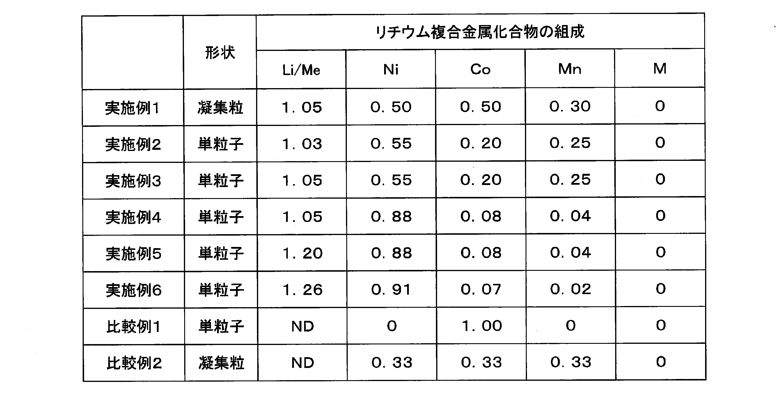


評価の結果、実施例1~6の正極活物質を用いた全固体リチウムイオン電池は、いずれも高い初期充電容量を示したのに対し、比較例1,2の正極活物質は、初期充電容量が低かった。
実施例、比較例の正極活物質について、液系リチウムイオン二次電池を作成し、評価したところ、表4に示すように、いずれの正極活物質も良好に使用可能と評価できた。
このように、液系リチウムイオン二次電池においてはいずれも良好に動作する正極活物質であっても、全固体リチウムイオン電池とすると、電池性能に大きな差が生じ、本発明に係る全固体リチウムイオン電池用正極活物質は良好な電池性能を示すことが分かった。
以上より、本発明が有用であることが分かった。
100…積層体、110…正極、111…正極活物質層、112…正極集電体、113…外部端子、120…負極、121…負極電解質層、122…負極集電体、123…外部端子、130…固体電解質層、200…外装体、200a…開口部、1000…全固体リチウムイオン電池
Claims (14)
- リチウム金属複合酸化物の結晶を含む粒子からなる全固体リチウムイオン電池用正極活物質であって、
前記リチウム金属複合酸化物は、層状構造を有し、且つ少なくともLiと遷移金属とを含有し、
前記粒子は、レーザー回折式粒度分布測定によって測定される体積基準の累積粒度分布について、小粒子側からの累積割合が10%、50%、90%となる粒子径をそれぞれD10、D50、D90としたとき、関係式(D90-D10)/D50≧0.90が成り立ち、
前記結晶は、CuKα線を使用したX線回折測定において2θ=18.7±2°の範囲内のピークにおける結晶子サイズαと、2θ=44.6±2°の範囲内のピークにおける結晶子サイズβとの比α/βが1.0以上である全固体リチウムイオン電池用正極活物質。 - 酸化物固体電解質を含む全固体リチウムイオン電池に用いられる請求項1の全固体リチウムイオン電池用正極活物質。
- 前記遷移金属が、Ni、Co、Mn、Ti、Fe、V及びWからなる群から選ばれる少なくとも1種である請求項1又は2に記載の全固体リチウムイオン電池用正極活物質。
- 前記リチウム金属複合酸化物は、下記式(1)で表される請求項3に記載の全固体リチウムイオン電池用正極活物質。
Li[Lix(Ni(1-y-z-w)CoyMnzMw)1-x]O2 (1)
(ただし、MはFe、Cu、Ti、Mg、Al、W、B、Mo、Nb、Zn、Sn、Zr、Ga及びVからなる群より選択される1種以上の元素であり、-0.10≦x≦0.30、0<y≦0.40、0≦z≦0.40及び0≦w≦0.10を満たす。) - 上記式(1)において1-y-z-w≧0.50、かつy≦0.30を満たす請求項4に記載の全固体リチウムイオン電池用正極活物質。
- 前記粒子は、一次粒子と、前記一次粒子が凝集して形成された二次粒子と、前記一次粒子及び前記二次粒子とは独立して存在する単粒子と、から構成され、
前記粒子における前記単粒子の含有率は、20%以上である請求項1から5のいずれか1項に記載の全固体リチウムイオン電池用正極活物質。 - 前記粒子は、前記粒子の表面に金属複合酸化物からなる被覆層を有する請求項1から6のいずれか1項に記載の全固体リチウムイオン電池用正極活物質。
- 請求項1から7のいずれか1項に記載の全固体リチウムイオン電池用正極活物質を含む電極。
- 固体電解質をさらに含む請求項8に記載の電極。
- 正極と、負極と、前記正極と前記負極とに挟持された固体電解質層と、を有し、
前記固体電解質層は、第1の固体電解質を含み、
前記正極は、前記固体電解質層に接する正極活物質層と、前記正極活物質層が積層された集電体と、を有し、
前記正極活物質層は、請求項1から7のいずれか1項に記載の全固体リチウムイオン電池用正極活物質又は請求項8もしくは9に記載の電極を含む全固体リチウムイオン電池。 - 前記正極活物質層は、前記全固体リチウムイオン電池用正極活物質と、第2の固体電解質とを含む請求項10に記載の全固体リチウムイオン電池。
- 前記第1の固体電解質と、前記第2の固体電解質とが同じ物質である請求項11に記載の全固体リチウムイオン電池。
- 前記第1の固体電解質は、非晶質構造を有する請求項10から12のいずれか1項に記載の全固体リチウムイオン電池。
- 前記第1の固体電解質は、酸化物固体電解質である請求項10から13のいずれか1項に記載の全固体リチウムイオン電池。
Priority Applications (4)
| Application Number | Priority Date | Filing Date | Title |
|---|---|---|---|
| EP20727134.7A EP3920275A4 (en) | 2019-03-29 | 2020-01-17 | ACTIVE MATERIAL OF POSITIVE ELECTRODE FOR ALL-SOLID LITHIUM-ION BATTERIES, ELECTRODE AND ALL-SOLID LITHIUM-ION BATTERY |
| KR1020207015125A KR102247128B1 (ko) | 2019-03-29 | 2020-01-17 | 전고체 리튬 이온 전지용 정극 활물질, 전극 및 전고체 리튬 이온 전지 |
| CN202080000842.0A CN111971821A (zh) | 2019-03-29 | 2020-01-17 | 全固态锂离子电池用正极活性物质、电极以及全固态锂离子电池 |
| US16/886,363 US20200313183A1 (en) | 2019-03-29 | 2020-05-28 | Positive electrode active material for all-solid-state lithium-ion battery, electrode, and all-solid-state lithium-ion battery |
Applications Claiming Priority (2)
| Application Number | Priority Date | Filing Date | Title |
|---|---|---|---|
| JP2019066770A JP6650064B1 (ja) | 2019-03-29 | 2019-03-29 | 全固体リチウムイオン電池用正極活物質、電極および全固体リチウムイオン電池 |
| JP2019-066770 | 2019-03-29 |
Related Child Applications (1)
| Application Number | Title | Priority Date | Filing Date |
|---|---|---|---|
| US16/886,363 Continuation US20200313183A1 (en) | 2019-03-29 | 2020-05-28 | Positive electrode active material for all-solid-state lithium-ion battery, electrode, and all-solid-state lithium-ion battery |
Publications (1)
| Publication Number | Publication Date |
|---|---|
| WO2020202708A1 true WO2020202708A1 (ja) | 2020-10-08 |
Family
ID=69568263
Family Applications (1)
| Application Number | Title | Priority Date | Filing Date |
|---|---|---|---|
| PCT/JP2020/001480 WO2020202708A1 (ja) | 2019-03-29 | 2020-01-17 | 全固体リチウムイオン電池用正極活物質、電極及び全固体リチウムイオン電池 |
Country Status (5)
| Country | Link |
|---|---|
| EP (1) | EP3920275A4 (ja) |
| JP (1) | JP6650064B1 (ja) |
| KR (1) | KR102247128B1 (ja) |
| CN (1) | CN111971821A (ja) |
| WO (1) | WO2020202708A1 (ja) |
Cited By (2)
| Publication number | Priority date | Publication date | Assignee | Title |
|---|---|---|---|---|
| US20210135281A1 (en) * | 2019-11-05 | 2021-05-06 | Seiko Epson Corporation | Solid composition and method for producing solid electrolyte |
| CN114804118A (zh) * | 2021-01-29 | 2022-07-29 | 中国科学技术大学 | 一种改性氧化亚硅材料及其制备方法,以及锂离子电池 |
Families Citing this family (11)
| Publication number | Priority date | Publication date | Assignee | Title |
|---|---|---|---|---|
| JP7198170B2 (ja) * | 2019-07-30 | 2022-12-28 | Jx金属株式会社 | 全固体リチウムイオン電池用正極活物質、全固体リチウムイオン電池用正極活物質の製造方法及び全固体リチウムイオン電池 |
| JP6857752B1 (ja) * | 2020-01-09 | 2021-04-14 | 住友化学株式会社 | リチウム金属複合酸化物、リチウム二次電池用正極活物質、リチウム二次電池用正極、リチウム二次電池及びリチウム金属複合酸化物の製造方法 |
| JP6734491B1 (ja) * | 2020-01-17 | 2020-08-05 | 住友化学株式会社 | 全固体リチウムイオン電池用正極活物質、電極及び全固体リチウムイオン電池 |
| JP2023551994A (ja) * | 2020-12-07 | 2023-12-13 | エルジー エナジー ソリューション リミテッド | リチウム二次電池用正極材、その製造方法及びこれを含むリチウム二次電池 |
| CN112591805B (zh) * | 2020-12-14 | 2023-09-26 | 荆门市格林美新材料有限公司 | 一种提高镍钴锰三元前驱体粒度分布宽度的方法 |
| JP7269266B2 (ja) * | 2021-01-25 | 2023-05-08 | プライムプラネットエナジー&ソリューションズ株式会社 | 非水電解質二次電池 |
| CN115548277A (zh) * | 2021-06-30 | 2022-12-30 | 北京当升材料科技股份有限公司 | 正极材料及其制备方法与应用、锂离子电池正极极片以及锂离子电池 |
| CN113972369B (zh) * | 2021-10-29 | 2023-06-30 | 宁波容百新能源科技股份有限公司 | 一种高压实密度三元正极材料 |
| KR20230070683A (ko) * | 2021-11-15 | 2023-05-23 | 에스케이온 주식회사 | 황화물계 전고체 전지용 양극 활물질, 이의 제조 방법, 이를 포함하는 양극 복합체 및 양극 복합체의 제조방법 |
| WO2023167235A1 (ja) * | 2022-03-03 | 2023-09-07 | 株式会社Gsユアサ | 蓄電素子及び蓄電装置 |
| WO2023238580A1 (ja) * | 2022-06-10 | 2023-12-14 | パナソニックホールディングス株式会社 | 被覆活物質、それを用いた電池、および、被覆活物質の製造方法 |
Citations (12)
| Publication number | Priority date | Publication date | Assignee | Title |
|---|---|---|---|---|
| JP2002201028A (ja) | 2000-11-06 | 2002-07-16 | Tanaka Chemical Corp | 高密度コバルトマンガン共沈水酸化ニッケル及びその製造法 |
| WO2007004590A1 (ja) * | 2005-07-01 | 2007-01-11 | National Institute For Materials Science | 全固体リチウム電池 |
| JP2009266728A (ja) * | 2008-04-28 | 2009-11-12 | Toyota Motor Corp | 抵抗層形成抑制コート層被覆正極活物質およびそれを用いた全固体リチウム二次電池 |
| JP2010245038A (ja) * | 2009-03-18 | 2010-10-28 | Idemitsu Kosan Co Ltd | 正極合材及びリチウム電池 |
| CN102544481A (zh) * | 2012-02-20 | 2012-07-04 | 东莞新能源科技有限公司 | 锂离子电池及其正极材料 |
| JP2014022204A (ja) * | 2012-07-19 | 2014-02-03 | Hitachi Ltd | リチウムイオン二次電池用活物質粒子およびそれを用いたリチウムイオン二次電池 |
| JP2015018678A (ja) * | 2013-07-10 | 2015-01-29 | 株式会社田中化学研究所 | リチウム二次電池用正極活物質、正極および二次電池 |
| WO2015182665A1 (ja) * | 2014-05-29 | 2015-12-03 | 住友化学株式会社 | リチウム二次電池用正極活物質、リチウム二次電池用正極及びリチウム二次電池 |
| JP2016024916A (ja) * | 2014-07-17 | 2016-02-08 | トヨタ自動車株式会社 | 全固体電池用電極及びその製造方法 |
| WO2016060105A1 (ja) * | 2014-10-15 | 2016-04-21 | 住友化学株式会社 | リチウム二次電池用正極活物質、リチウム二次電池用正極及びリチウム二次電池 |
| JP2018014317A (ja) | 2016-07-06 | 2018-01-25 | 富士フイルム株式会社 | 固体電解質組成物、固体電解質含有シートおよび全固体二次電池ならびに固体電解質含有シートおよび全固体二次電池の製造方法 |
| JP2019066770A (ja) | 2017-10-04 | 2019-04-25 | シャープ株式会社 | 表示駆動装置および表示装置 |
Family Cites Families (3)
| Publication number | Priority date | Publication date | Assignee | Title |
|---|---|---|---|---|
| WO2010101306A2 (ja) * | 2009-06-25 | 2010-09-10 | 日本碍子株式会社 | 正極活物質及びリチウム二次電池 |
| US8795902B2 (en) * | 2010-04-13 | 2014-08-05 | Toyota Jidosha Kabushiki Kaisha | Solid electrolyte material, lithium battery, and method of producing solid electrolyte material |
| CN109643790B (zh) * | 2016-08-30 | 2022-01-04 | 富士胶片株式会社 | 固体电解质组合物、含固体电解质的片材及全固态二次电池以及含固体电解质的片材及全固态二次电池的制造方法 |
-
2019
- 2019-03-29 JP JP2019066770A patent/JP6650064B1/ja active Active
-
2020
- 2020-01-17 KR KR1020207015125A patent/KR102247128B1/ko active IP Right Grant
- 2020-01-17 CN CN202080000842.0A patent/CN111971821A/zh active Pending
- 2020-01-17 EP EP20727134.7A patent/EP3920275A4/en active Pending
- 2020-01-17 WO PCT/JP2020/001480 patent/WO2020202708A1/ja unknown
Patent Citations (12)
| Publication number | Priority date | Publication date | Assignee | Title |
|---|---|---|---|---|
| JP2002201028A (ja) | 2000-11-06 | 2002-07-16 | Tanaka Chemical Corp | 高密度コバルトマンガン共沈水酸化ニッケル及びその製造法 |
| WO2007004590A1 (ja) * | 2005-07-01 | 2007-01-11 | National Institute For Materials Science | 全固体リチウム電池 |
| JP2009266728A (ja) * | 2008-04-28 | 2009-11-12 | Toyota Motor Corp | 抵抗層形成抑制コート層被覆正極活物質およびそれを用いた全固体リチウム二次電池 |
| JP2010245038A (ja) * | 2009-03-18 | 2010-10-28 | Idemitsu Kosan Co Ltd | 正極合材及びリチウム電池 |
| CN102544481A (zh) * | 2012-02-20 | 2012-07-04 | 东莞新能源科技有限公司 | 锂离子电池及其正极材料 |
| JP2014022204A (ja) * | 2012-07-19 | 2014-02-03 | Hitachi Ltd | リチウムイオン二次電池用活物質粒子およびそれを用いたリチウムイオン二次電池 |
| JP2015018678A (ja) * | 2013-07-10 | 2015-01-29 | 株式会社田中化学研究所 | リチウム二次電池用正極活物質、正極および二次電池 |
| WO2015182665A1 (ja) * | 2014-05-29 | 2015-12-03 | 住友化学株式会社 | リチウム二次電池用正極活物質、リチウム二次電池用正極及びリチウム二次電池 |
| JP2016024916A (ja) * | 2014-07-17 | 2016-02-08 | トヨタ自動車株式会社 | 全固体電池用電極及びその製造方法 |
| WO2016060105A1 (ja) * | 2014-10-15 | 2016-04-21 | 住友化学株式会社 | リチウム二次電池用正極活物質、リチウム二次電池用正極及びリチウム二次電池 |
| JP2018014317A (ja) | 2016-07-06 | 2018-01-25 | 富士フイルム株式会社 | 固体電解質組成物、固体電解質含有シートおよび全固体二次電池ならびに固体電解質含有シートおよび全固体二次電池の製造方法 |
| JP2019066770A (ja) | 2017-10-04 | 2019-04-25 | シャープ株式会社 | 表示駆動装置および表示装置 |
Non-Patent Citations (2)
| Title |
|---|
| See also references of EP3920275A4 |
| YOSHIO WASEDAEIICHIRO MATSUBARA: "X-ray structural analysis-determining arrangement of atoms", 30 April 2002 |
Cited By (3)
| Publication number | Priority date | Publication date | Assignee | Title |
|---|---|---|---|---|
| US20210135281A1 (en) * | 2019-11-05 | 2021-05-06 | Seiko Epson Corporation | Solid composition and method for producing solid electrolyte |
| CN114804118A (zh) * | 2021-01-29 | 2022-07-29 | 中国科学技术大学 | 一种改性氧化亚硅材料及其制备方法,以及锂离子电池 |
| CN114804118B (zh) * | 2021-01-29 | 2023-08-29 | 中国科学技术大学 | 一种改性氧化亚硅材料及其制备方法,以及锂离子电池 |
Also Published As
| Publication number | Publication date |
|---|---|
| JP6650064B1 (ja) | 2020-02-19 |
| CN111971821A (zh) | 2020-11-20 |
| KR20200117977A (ko) | 2020-10-14 |
| EP3920275A4 (en) | 2022-06-01 |
| EP3920275A1 (en) | 2021-12-08 |
| JP2020167042A (ja) | 2020-10-08 |
| KR102247128B1 (ko) | 2021-04-30 |
Similar Documents
| Publication | Publication Date | Title |
|---|---|---|
| WO2020202708A1 (ja) | 全固体リチウムイオン電池用正極活物質、電極及び全固体リチウムイオン電池 | |
| JP6742547B1 (ja) | 全固体リチウムイオン電池用正極活物質、電極及び全固体リチウムイオン電池 | |
| JP6780140B1 (ja) | 全固体リチウムイオン電池用混合粉末、全固体リチウムイオン電池用混合ペースト、電極および全固体リチウムイオン電池 | |
| JP6705068B1 (ja) | 全固体リチウムイオン電池用正極活物質、電極および全固体リチウムイオン電池 | |
| US20200313183A1 (en) | Positive electrode active material for all-solid-state lithium-ion battery, electrode, and all-solid-state lithium-ion battery | |
| WO2021145438A1 (ja) | 全固体リチウムイオン電池用正極活物質、電極及び全固体リチウムイオン電池 | |
| WO2021145444A1 (ja) | 全固体リチウムイオン電池用正極活物質、電極及び全固体リチウムイオン電池 | |
| JP7194703B2 (ja) | 全固体リチウムイオン電池用正極活物質、電極および全固体リチウムイオン電池 | |
| JP6810287B1 (ja) | 全固体リチウムイオン電池用正極活物質、電極及び全固体リチウムイオン電池 | |
| JP6850375B1 (ja) | 全固体リチウムイオン電池用正極活物質、電極及び全固体リチウムイオン電池 | |
| WO2021225095A1 (ja) | リチウム金属複合酸化物、リチウム二次電池用正極活物質、リチウム二次電池用正極及びリチウム二次電池 | |
| WO2021225094A1 (ja) | リチウム二次電池用正極活物質前駆体、リチウム二次電池用正極活物質前駆体の製造方法及びリチウム二次電池用正極活物質の製造方法 |
Legal Events
| Date | Code | Title | Description |
|---|---|---|---|
| 121 | Ep: the epo has been informed by wipo that ep was designated in this application |
Ref document number: 20727134 Country of ref document: EP Kind code of ref document: A1 |
|
| NENP | Non-entry into the national phase |
Ref country code: DE |
|
| ENP | Entry into the national phase |
Ref document number: 2020727134 Country of ref document: EP Effective date: 20211029 |