WO2020171157A1 - ホルダ、切削工具、切削加工物の製造方法及びデータの収集方法 - Google Patents
ホルダ、切削工具、切削加工物の製造方法及びデータの収集方法 Download PDFInfo
- Publication number
- WO2020171157A1 WO2020171157A1 PCT/JP2020/006694 JP2020006694W WO2020171157A1 WO 2020171157 A1 WO2020171157 A1 WO 2020171157A1 JP 2020006694 W JP2020006694 W JP 2020006694W WO 2020171157 A1 WO2020171157 A1 WO 2020171157A1
- Authority
- WO
- WIPO (PCT)
- Prior art keywords
- antenna member
- cutting tool
- antenna
- resin member
- main body
- Prior art date
- Legal status (The legal status is an assumption and is not a legal conclusion. Google has not performed a legal analysis and makes no representation as to the accuracy of the status listed.)
- Ceased
Links
Images




Classifications
-
- B—PERFORMING OPERATIONS; TRANSPORTING
- B23—MACHINE TOOLS; METAL-WORKING NOT OTHERWISE PROVIDED FOR
- B23B—TURNING; BORING
- B23B27/00—Tools for turning or boring machines; Tools of a similar kind in general; Accessories therefor
- B23B27/14—Cutting tools of which the bits or tips or cutting inserts are of special material
-
- B—PERFORMING OPERATIONS; TRANSPORTING
- B23—MACHINE TOOLS; METAL-WORKING NOT OTHERWISE PROVIDED FOR
- B23Q—DETAILS, COMPONENTS, OR ACCESSORIES FOR MACHINE TOOLS, e.g. ARRANGEMENTS FOR COPYING OR CONTROLLING; MACHINE TOOLS IN GENERAL CHARACTERISED BY THE CONSTRUCTION OF PARTICULAR DETAILS OR COMPONENTS; COMBINATIONS OR ASSOCIATIONS OF METAL-WORKING MACHINES, NOT DIRECTED TO A PARTICULAR RESULT
- B23Q17/00—Arrangements for observing, indicating or measuring on machine tools
- B23Q17/09—Arrangements for observing, indicating or measuring on machine tools for indicating or measuring cutting pressure or for determining cutting-tool condition, e.g. cutting ability, load on tool
- B23Q17/0952—Arrangements for observing, indicating or measuring on machine tools for indicating or measuring cutting pressure or for determining cutting-tool condition, e.g. cutting ability, load on tool during machining
- B23Q17/0971—Arrangements for observing, indicating or measuring on machine tools for indicating or measuring cutting pressure or for determining cutting-tool condition, e.g. cutting ability, load on tool during machining by measuring mechanical vibrations of parts of the machine
-
- B—PERFORMING OPERATIONS; TRANSPORTING
- B23—MACHINE TOOLS; METAL-WORKING NOT OTHERWISE PROVIDED FOR
- B23Q—DETAILS, COMPONENTS, OR ACCESSORIES FOR MACHINE TOOLS, e.g. ARRANGEMENTS FOR COPYING OR CONTROLLING; MACHINE TOOLS IN GENERAL CHARACTERISED BY THE CONSTRUCTION OF PARTICULAR DETAILS OR COMPONENTS; COMBINATIONS OR ASSOCIATIONS OF METAL-WORKING MACHINES, NOT DIRECTED TO A PARTICULAR RESULT
- B23Q17/00—Arrangements for observing, indicating or measuring on machine tools
- B23Q17/09—Arrangements for observing, indicating or measuring on machine tools for indicating or measuring cutting pressure or for determining cutting-tool condition, e.g. cutting ability, load on tool
- B23Q17/0952—Arrangements for observing, indicating or measuring on machine tools for indicating or measuring cutting pressure or for determining cutting-tool condition, e.g. cutting ability, load on tool during machining
- B23Q17/0985—Arrangements for observing, indicating or measuring on machine tools for indicating or measuring cutting pressure or for determining cutting-tool condition, e.g. cutting ability, load on tool during machining by measuring temperature
-
- B—PERFORMING OPERATIONS; TRANSPORTING
- B23—MACHINE TOOLS; METAL-WORKING NOT OTHERWISE PROVIDED FOR
- B23B—TURNING; BORING
- B23B2260/00—Details of constructional elements
- B23B2260/128—Sensors
-
- B—PERFORMING OPERATIONS; TRANSPORTING
- B23—MACHINE TOOLS; METAL-WORKING NOT OTHERWISE PROVIDED FOR
- B23B—TURNING; BORING
- B23B2260/00—Details of constructional elements
- B23B2260/128—Sensors
- B23B2260/1285—Vibration sensors
-
- B—PERFORMING OPERATIONS; TRANSPORTING
- B23—MACHINE TOOLS; METAL-WORKING NOT OTHERWISE PROVIDED FOR
- B23B—TURNING; BORING
- B23B29/00—Holders for non-rotary cutting tools; Boring bars or boring heads; Accessories for tool holders
- B23B29/04—Tool holders for a single cutting tool
- B23B29/12—Special arrangements on tool holders
Definitions
- the present disclosure generally relates to a holder capable of measuring the state of cutting in cutting of a work material. More specifically, the present invention relates to a holder capable of communicating the measured cutting state with the outside.
- Patent Document 1 As a cutting tool used when cutting a work material such as metal, for example, a cutting tool described in JP 2012-20359 A (Patent Document 1) is known.
- the cutting tool described in Patent Document 1 includes a main body portion, a cutting blade, a sensor portion, a cable member, and a communication portion. The state of cutting can be measured by detachably connecting the communication part to the cable member.
- the communication unit is connected to the main body via the cable member. Therefore, the number of wirings increases together with the power wiring for supplying power to the communication unit, and the handling of the wirings becomes complicated.
- a holder has a body, an antenna member and a sensor.
- the main body has a rod shape extending from the first end toward the second end along the central axis. Further, the main body has a metal member and a first resin member.
- the metal member has a pocket into which an insert having a cutting edge can be attached.
- the first resin member is located closer to the second end than the metal member.
- the antenna member is covered with the first resin member.
- the sensor is located closer to the pocket than the antenna member, is wired to the antenna member, and can measure the state of the main body.
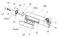
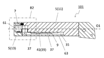
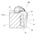
- FIG. 8 It is a perspective view which shows the cutting tool of an example which is not limited. It is a disassembled perspective view of the cutting tool shown in FIG. It is an enlarged view of the area
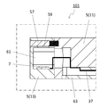
- FIG. It is an enlarged view of the area
- the cutting tool 101 having the holders 1 of the plurality of embodiments without limitation of the present disclosure will be described in detail with reference to the drawings.
- the cutting tool 101 may include any component not shown in the referenced figures.
- the dimensions of the members in each drawing do not faithfully represent the actual dimensions of the constituent members and the dimensional ratios of the respective members.
- the cutting tool 101 may include, for example, a turning tool, a rolling tool, a drill, and the like.
- Turning tools may include outer diameter machining tools, inner diameter machining tools, grooving tools and parting tools. Milling tools, end mills and the like may be mentioned as milling tools.
- the cutting tool 101 of the non-limiting embodiment may include the holder 1 and the cutting insert 3 (hereinafter, also simply referred to as the insert 3).
- the cutting tool 101 in the non-limiting example shown in FIG. 1 is a turning tool. As described above, there is no problem even if the cutting tool 101 is a rolling tool or a drill.
- the holder 1 of the non-limiting embodiment may include the main body 5, the antenna member 7, and the sensor 9.
- the body 5 in a non-limiting embodiment may be rod-shaped extending from the first end 1a to the second end 1b.
- the first end 1a is the front end and the second end 1b is the rear end.
- the body 5 may be square pole shaped.
- the main body 5 has the central axis O1 and can be said to extend along the central axis O1.
- the main body 5 may be composed of a plurality of members. For example, as shown in FIG. 1, you may have the metal member 11 located in the 1st end 1a side, and the 1st resin member 13 located nearer the 2nd end than the metal member 11.
- the metal member 11 may include the first end 1a as in a non-limiting example shown in FIG. Further, the first resin member 13 may include the second end 1b as in a non-limiting example shown in FIG.
- the first resin member 13 may contact the metal member 11. Further, the first resin member 13 may be separated from the metal member 11 by positioning another member between the first resin member 13 and the metal member 11. When the first resin member 13 contacts the metal member 11, the first resin member 13 may be bonded to the metal member 11 or may simply contact.
- the main body 5 may have a first end surface 15, a second end surface 17, a first side surface 19, a second side surface 21, a third side surface 23, and a fourth side surface 25.
- the first end surface 15 may be located at the first end 1a.
- the second end surface 17 may be located at the second end 1b.
- the first side surface 19, the second side surface 21, the third side surface 23, and the fourth side surface 25 may each extend from the first end 1a to the second end 1b.
- the second side surface 21 may be located on the opposite side of the first side surface 19.
- the third side surface 23 and the fourth side surface 25 may be located between the first side surface 19 and the second side surface 21, respectively.
- the fourth side surface 25 may be located on the opposite side of the third side surface 23.
- the third side surface 23 and the fourth side surface 25 may be orthogonal to the first side surface 19 and the second side surface 21, respectively.
- the metal member 11 in the non-limiting embodiment may have the pocket 27.
- An insert 3 having a cutting edge 29 can be attached to the pocket 27.
- the pocket 27 may be located on the side of the first end 1a.
- the pocket 27 in the non-limiting example shown in FIG. 1 may be open to the first end surface 15, the first side surface 19 and the third side surface 23.
- the insert 3 has a cutting edge 29, and may have a function of cutting a work material during cutting.
- the insert 3 may have a rectangular plate shape and have a first surface 31 and a second surface 33.
- the first surface 31 may have a first region 31a in which chips flow.
- the first region 31a is generally called a rake face.
- the second surface 33 may be adjacent to the first surface 31.
- the second surface 33 may have a second region 33a facing the processed surface of the work material.
- the second region 33a is generally called a flank.
- the cutting edge 29 may be located at at least a part of the intersection of the first surface 31 and the second surface 33.
- the first surface 31 of the insert 3 may be positioned substantially parallel to the third side surface 23 of the body 5 as in a non-limiting example shown in FIG.
- the first surface 31 may be positioned so as to be substantially orthogonal to the first side surface 19 and the second side surface 21.
- the main component force is easily applied to the cutting tool 101 in a direction substantially orthogonal to the third side surface 23.
- the shape of the insert 3 is not limited to the above form.
- the insert 3 of the non-limiting embodiment may have a rectangular plate shape in which the shape of the first surface 31 is a quadrangle.
- the shape of the first surface 31 may be, for example, triangular, pentagonal or hexagonal. That is, the insert 3 may have, for example, a triangular plate shape, a pentagonal plate shape, or a hexagonal plate shape.
- the size of the insert 3 is not particularly limited.
- the length of one side of the first surface 31 may be set to about 3 to 20 mm.
- the height of the insert 3 shown in the direction orthogonal to the first surface 31 may be set to about 5 to 20 mm.
- the material of the insert 3 may include, for example, cemented carbide and cermet.
- the composition of the cemented carbide may include, for example, WC-Co, WC-TiC-Co and WC-TiC-TaC-Co.
- WC, TiC, and TaC may be hard particles
- Co may be a binder phase.
- the cermet may be a sintered composite material in which a metal is combined with a ceramic component.
- the cermet may include a titanium compound containing titanium carbide (TiC) and/or titanium nitride (TiN) as a main component.
- TiC titanium carbide
- TiN titanium nitride
- the material of the insert 3 is not limited to the above composition.
- the surface of the insert 3 may be coated with a film using a chemical vapor deposition (CVD) method or a physical vapor deposition (PVD) method.
- the coating composition may include titanium carbide (TiC), titanium nitride (TiN), titanium carbonitride (TiCN), alumina (Al 2 O 3 ), and the like.
- the size of the main body 5 is not particularly limited.
- the length from the first end 1a to the second end 1b may be set to about 50 to 200 mm.
- the distance between the first side surface 19 and the second side surface 21 may be set to about 5 to 30 mm.
- the distance between the third side surface 23 and the fourth side surface 25 may be set to about 5 to 30 mm.
- the antenna member 7 may be covered with the first resin member 13 and may be connected to the sensor 9.
- the information of the main body 5 measured by the sensor 9 is transmitted to the antenna member 7, and the antenna member 7 can wirelessly communicate with the outside.
- the antenna member 7 in the non-limiting embodiment is located inside the body 5 rather than being connected to the body 5 by a cable member. Therefore, a cable member for connecting the sensor 9 and the antenna member 7 is unnecessary, and the holder 1 can be easily handled.
- the antenna member 7 is located inside the main body 5 while being covered with the first resin member 13.
- the first resin member 13 is located near the second end 1b.
- the second end 1b is opposite to the side of the first end 1a where the pocket 27 is located. That is, the antenna member 7 located near the second end 1b is largely separated from the pocket 27 located on the first end 1a side.
- Chips are generated at the cutting edge 29 during cutting of a work material for manufacturing a cut product. Further, a cooling liquid (coolant) may be jetted toward the cutting edge 29.
- a cooling liquid coolant
- the antenna member 7 is less likely to be affected by the scattering of chips and the injection of the cooling liquid. Therefore, the durability of the antenna member 7 is high.
- the antenna member 7 when the antenna member 7 is not only largely separated from the pocket 27 but also the antenna member 7 is covered with the first resin member 13, the first resin member 13 can function as a cover for the antenna member 7. It is possible. Therefore, the antenna member 7 is less likely to be affected by the scattering of chips and the injection of the cooling liquid, and the durability of the antenna member 7 is further enhanced.
- a cutting load may be applied to the holder 1 from the first end 1a side to the second end 1b side during cutting.
- a back force may be applied from the first end 1a side toward the second end 1b side.
- the holder 1 can be supported by the first resin member 13 instead of the antenna member 7. Therefore, the displacement of the holder 1 is unlikely to occur.
- the antenna member 7 has a flat plate shape having a pair of main surfaces 7a.
- the pair of main surfaces 7a may be parallel to the central axis O1.
- the radio signal from the antenna member 7 has directivity
- the radio signal from the antenna member 7 easily travels in the direction orthogonal to the pair of main surfaces.
- the wireless signal from the antenna member 7 has characteristics in all directions, the antenna characteristics are improved because it is easy to ensure that there is no metal around.
- the sensor 9 is located closer to the pocket 27 than the antenna member 7.
- the sensor 9 may be located on the surface of the main body 5 or may be located inside the main body 5.
- the first side surface 19 of the body 5 has a recess 35 in which the sensor 9 is located.
- the recess 35 is located between the pocket 27 and the second end surface 17 on the first side surface 19.
- the sensor 9 is attached to the main body 5 more than when the sensor 9 is located inside the main body 5. It's easy. Further, as compared with the case where the sensor 9 is simply located on the surface of the main body 5, the sensor 9 is less likely to be affected by the scattering of chips and the injection of the cooling liquid.
- the sensor 9 is a member that can measure the state of the main body 5 during cutting.
- Examples of the state of the main body 5 may include physical quantities such as temperature, acceleration, vibration, strain, internal stress, and wear.
- Measuring the state of the main body 5 means measuring at least one information of the physical quantities represented by the above in the main body 5.
- the measurement target is not limited to information in a static state, but may be information in a dynamic state, that is, a change in state.
- the information of the measurement target is the temperature. Further, it is assumed that the temperature of the main body 5 before cutting is 20° and the temperature of the main body 5 rises to 80° during cutting. At this time, 20°, which is the temperature of the main body 5 before cutting, is information in a static state regarding the temperature. Further, the rise in the temperature of the main body 5 from 20° to 80° is the information in the dynamic state regarding the temperature. Either one of these pieces of information may be measured, or both of them may be measured.
- the holder 1 when the holder 1 has a thermocouple as the sensor 9, it is possible to measure the temperature of the main body 5. Even when the holder 1 has a piezoelectric sensor using a piezo element, it is possible to measure acceleration, vibration, strain, internal stress, and the like. Further, the holder 1 may have a wiring circuit that functions as the sensor 9. Specifically, when the wiring circuit wears with the wear of the main body 5 and the resistance value of the circuit changes, the wear state of the main body 5 may be measured by the change in the resistance value.
- the state of the main body 5 that can be measured by the sensor 9 is not limited to the above physical property values. Further, the sensor 9 is not limited to the above specific example, and other elements not particularly described may be used as long as they can measure the physical property values of the main body 5 exemplified above. For example, a camera and a microphone may be mentioned.
- the state of the cutting edge 29 of the insert 3 can be evaluated.
- the state of the insert 3 is easily evaluated with high accuracy.
- first distance L1 is shorter than the distance from the sensor 9 to the second end 1b (second distance L2)
- second distance L2 the state of the insert 3 is more accurate. Easy to be evaluated. This is because the sensor 9 is located near the insert 3 located in the pocket 27 due to the relatively short distance from the sensor 9 to the pocket 27.
- the holder 1 may have a cover member 63.
- the cover member 63 may be located at the opening of the recess 35 as in a non-limiting example shown in FIG. In other words, the cover member 63 is located above the sensor 9.
- the sensor 9 is less likely to be damaged during cutting. In addition, it can have waterproofness against coolant.
- the sensor 9 is wired to the antenna member 7.
- the holder 1 of the non-limiting embodiment has a connecting portion 37 that connects the sensor 9 and the antenna member 7 by wire.
- the connection part 37 may include, for example, a wiring and a circuit using a conductor. Note that the transmission of information from the sensor 9 to the antenna member 7 is not limited to the above, and may be performed using optical wiring, for example.
- the second distance L2 may be longer than the third distance L3 or shorter than the third distance L3.
- the second distance L2 is shorter than the third distance L3, that is, when the sensor 9 is located closer to the second end 1b than the pocket 27, the connecting portion 37 is unlikely to be longer than necessary. Therefore, deterioration of durability due to deterioration of the connecting portion 37 is easily avoided. Moreover, the connection state of the sensor 9 and the antenna member 7 is easily stabilized.
- the sensor 9 and the antenna member 7 may be directly connected to each other, but may be wired to each other via, for example, the module 41 including the first control unit 39.
- the module 41 including the first control unit 39.
- a detection unit 45 that detects the first signal 43 based on the physical quantity measured by the sensor 9, and a first control unit 39 that controls the first signal 43 detected by the detection unit 45.
- the output unit 49 that outputs the signal controlled by the first control unit 39 to the antenna member 7 as the second signal 47.
- the wireless communication unit 51 When the external member that wirelessly communicates with the antenna member 7 is the wireless communication unit 51, the information of the main body 5 measured by the sensor 9 is transmitted from the antenna member 7 and is received by the wireless communication unit 51. The information of the main body 5 received by the wireless communication unit 51 is transmitted to the evaluation unit 53. The evaluation unit 53 evaluates the state of the main body 5.
- the processing conditions such as the feed amount, the cutting amount, the rotation speed of the work material, and the injection amount of the coolant (coolant) may be changed.
- the cutting process may be stopped in some cases.
- the cutting tool 101 in the non-limiting example of the embodiment is a turning tool, but when the cutting tool 101 is a rolling tool or a drill, the rotation speed of the cutting tool 101 can also be mentioned as a processing condition that can be changed. ..
- the wireless communication described above is not limited to transmission of information from the antenna member 7 to the wireless communication unit 51, and is a concept including transmission of information from the wireless communication unit 51 to the antenna member 7.
- the wireless communication described above may be bidirectional information transmission/reception between the antenna member 7 and the wireless communication unit 51.
- the material of the metal member 11 may be, for example, steel, cast iron or the like. From the viewpoint of enhancing the toughness of the metal member 11, steel may be used among these materials.
- the main body 5 When the metal member 11 and the first resin member 13 are in contact with each other, the main body 5 may have a cavity 61 surrounded by the metal member 11 and the first resin member 13.
- the antenna member 7 may be located in this cavity 61.
- the cutting load transmitted to the antenna member 7 when a cutting load is applied to the holder 1 from the first end 1a side to the second end 1b side during cutting, as in the above-described back force component. Are easily released in the cavity 61. Therefore, the antenna member 7 is less likely to be crushed by the metal member 11 and the first resin member 13.
- the antenna member 7 may be in contact with the metal member 11 or may be separated from the metal member 11. In other words, there may be a gap between the metal member 11 and the antenna member 7. The back force described above is easily released in this gap. Therefore, the antenna member 7 is less likely to be crushed by the metal member 11 and the first resin member 13.
- the holder 1 may further include a second resin member 55 in addition to the first resin member 13 as in a non-limiting example shown in FIG.
- the second resin member 55 may be located between the metal member 11 and the first resin member 13 as in a non-limiting example shown in FIG.
- the second resin member 55 may be an annular shape that surrounds the antenna member 7 when seen in a plan view from the second end 1b side.
- the antenna member 7 is less likely to deteriorate, and the influence on the wireless communication between the antenna member 7 and the outside is small.
- the hardness of the first resin member 13 may be higher than the hardness of the second resin member 55.
- the first resin member 13 facilitates stable support of the holder 1.
- the hardness of the second resin member 55 is relatively low, the airtightness of the antenna member 7 is enhanced by elastically deforming the second resin member 55 while maintaining the shape of the first resin member 13.
- the hardness of the first resin member 13 and the second resin member 55 can be evaluated by, for example, performing a Rockwell hardness test (JIS Z 2245:2016).
- the first resin member 13 and the second resin member 55 are not limited to particular resins.
- resins one selected from polycarbonate resin, polyethylene terephthalate resin, acrylic resin, polyvinyl chloride resin, silicone resin and epoxy resin may be used.
- the first resin member 13 may be bonded to the metal member 11 with an adhesive, or may be fixed with a screw member 57. When the first resin member 13 is bonded to the metal member 11 with an adhesive, the airtightness of the antenna member 7 is likely to be enhanced.
- the antenna member 7 can be easily replaced, for example, when the antenna member 7 deteriorates.
- the first resin member 13 may be fixed to the metal member 11 by the screw member 57.
- the first resin member 13 may have one or a plurality of through holes 59 extending from the second end 1b side toward the first end 1a along the central axis O1.
- the holder 1 may further include one or a plurality of screw members 57 that are inserted into the through holes 59 and fix the first resin member 13 to the metal member 11.
- the one or more through holes 59 may be located on the outer peripheral side of the second resin member 55 when seen in a plan view from the second end 1b side.
- the pressing force generated when screwing is easily transmitted from the first resin member 13 to the second resin member 55, but difficult to be transmitted to the antenna member 7. Therefore, the airtightness of the antenna member 7 is easily enhanced, and the antenna member 7 is less likely to be crushed.
- the insert 3 in the cutting tool 101 may have the cutting edge 29.
- the antenna member 7 may be separated from the cutting edge 29 when seen in a plan view from the first end 1a side. During cutting, a cutting load is generated on the cutting edge 29, and this cutting load is transmitted to the holder 1.
- the antenna member 7 is separated from the cutting edge 29 when seen through the plane from the first end 1a side, the above-mentioned back force is hard to be transmitted to the antenna member 7. Therefore, the durability of the antenna member 7 is high.
- the cutting edge 29 projects in the first direction (leftward in FIG. 5) from the main body 5, and the antenna member 7 is based on the central axis O1.
- the durability of the antenna member 7 is further enhanced when the antenna member 7 is located on the side opposite to the first direction (right side in FIG. 5).
- Electric power may be supplied to the antenna member 7 and the module 41 from an external power source, or the holder 1 may have a battery and electric power may be supplied from this battery.
- the holder 1 may have a battery and electric power may be supplied from this battery.
- the cut product 201 can be produced by cutting the work material 203.
- the method for manufacturing the machined product 201 in the non-limiting embodiment may include the following steps. That is, (1) a step of rotating the work material 203, (2) a step of bringing the cutting material 101 represented by the above-described non-limiting embodiment into contact with the rotating work material 203, (3) a step of separating the cutting tool 101 from the work material 203, Equipped with.
- the work material 203 may be rotated around the axis O2 and the cutting tool 101 may be relatively brought close to the work material 203.
- the cutting edge of the cutting tool 101 may be brought into contact with the work material 203 to cut the work material 203.
- the cutting tool 101 may be relatively separated from the work material 203.
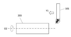
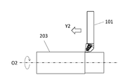
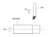
- the cutting tool 101 may be moved in the Y1 direction while the shaft O2 is fixed and the work material 203 is rotated to move the work material 203 closer to the work material 203. Further, in FIG. 12, the work material 203 may be cut by bringing the cutting edge of the insert into contact with the rotating work material 203. In addition, in FIG. 13, the cutting tool 101 may be moved away in the Y2 direction while the work material 203 is being rotated.
- the cutting tool 101 in each step, is moved to bring the cutting tool 101 into contact with the work material 203, or the cutting tool 101 is removed from the work material 203. Although separated, it is of course not limited to such a form.
- the work material 203 may be brought close to the cutting tool 101.
- the work material 203 may be moved away from the cutting tool 101.
- the process of keeping the workpiece 203 rotated and bringing the cutting edge of the insert into contact with different portions of the workpiece 203 may be repeated.
- carbon steel, alloy steel, stainless steel, cast iron, non-ferrous metal, etc. can be cited as typical examples of the material of the work material 203.
- the state of the main body 5 is changed by cutting the work material 203 in the above step (2). For example, since a cutting load is applied to the cutting tool 101 during cutting, the main body 5 vibrates, and strain and internal stress occur in the main body 5. Further, the temperature of the main body 5 rises due to the cutting work, and the vibration mode of the main body 5 changes due to wear of the cutting edge.
- the sensor 9 when the sensor 9 is a thermocouple, the temperature of the main body 5 can be measured.
- the sensor 9 is a piezoelectric sensor, vibration, strain and internal stress of the main body 5 can be measured. In this way, the sensor 9 has a measuring means for measuring the state of the main body 5.
- Information measured by the sensor 9 may be transmitted from the sensor 9 to the antenna member 7. That is, the sensor 9 may have the first transmission means C1 that transmits the measured information to the antenna member 7, as shown in FIG.
- the information transmitted from the sensor 9 may be transmitted to the outside from the antenna member 7. That is, the antenna member 7 may include the second transmission unit C2 that wirelessly communicates the information transmitted from the sensor 9 with the outside.
- the information transmitted from the antenna member 7 to the outside may be received by the wireless communication unit 51 and transmitted to the evaluation unit 53, for example.
- the information transmitted to the evaluation unit 53 can be compared with the information based on the previously measured result, and the state of the main body 5 can be evaluated. That is, the evaluation unit 53 has first evaluation means for evaluating the state of the main body 5.
- the processing conditions such as the feed amount, the rotation speed of the work material 203, and the injection amount of the cooling liquid may be changed.
- the changed machining conditions may be transmitted to the second controller of the machine tool. That is, the evaluation unit 53 sends the second evaluation unit that evaluates the processing condition based on the result evaluated by the first evaluation unit and the changed processing condition evaluated by the second evaluation unit to the wireless communication unit 51. And a third transmitting means C3 for transmitting.
- the wireless communication unit 51 may include a fourth transmission unit C4 that transmits information to the second control unit of the machine tool.
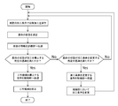
- the modified processing conditions described above may be transmitted to the second control unit by the fourth transmission unit C4. Then, as shown in FIG. 15, the cutting process may be continued or the cutting process may be stopped depending on the changed processing conditions. By the above process, cutting can be performed under appropriate processing conditions.
- the evaluation unit 53 may also include a third evaluation unit that evaluates whether or not the cutting tool 101 has been separated from the work material 203. In the step (3) described above, the cutting tool 101 is separated from the work material 203. Therefore, the vibration, strain and/or internal stress of the main body 5 can be almost zero.
- the cutting tool 101 may be evaluated that the cutting tool 101 has been separated from the work material 203 when the information regarding vibration, strain, internal stress, etc. has fallen below a predetermined strength for a certain period of time.
- wireless communication between the antenna member 7 and the outside is temporarily performed in order to suppress power consumption of the battery. May be stopped at.
- the wireless communication between the antenna member 7 and the outside may be temporarily stopped by transmitting a signal for temporarily stopping the wireless communication from the wireless communication unit 51 to the second control unit.
- the machine tool has exemplified the configuration having two control units, that is, the first control unit 39 and the second control unit.
- the machine tool is configured to have only one controller having the functions of the first controller 39 and the second controller.
Landscapes
- Engineering & Computer Science (AREA)
- Mechanical Engineering (AREA)
- Cutting Tools, Boring Holders, And Turrets (AREA)
- Milling Processes (AREA)
- Machine Tool Sensing Apparatuses (AREA)
- Drilling Tools (AREA)
Abstract
ホルダ(1)は、本体(5)、アンテナ部材(7)及びセンサ(9)を有する。本体(5)は、中心軸に沿って、第1端から第2端に向かって延びた棒形状である。また、本体(5)は、金属部材(11)及び第1樹脂部材(13)を有する。金属部材(11)は、切刃(29)を有するインサート(3)を取り付けることが可能なポケット(27)を有する。第1樹脂部材(13)は、金属部材(11)よりも第2端の近くに位置する。アンテナ部材(7)は、第1樹脂部材(13)に覆われる。センサ(9)は、アンテナ部材(7)よりもポケット(27)の近くに位置して、アンテナ部材(7)に有線接続され、且つ、本体(5)の状態を測定することが可能である。そして、この構成により配線の取り扱いが煩雑になるという課題を解決できる。
Description
本出願は、2019年2月20日に出願された日本国特許出願2019-028711号の優先権を主張するものであり、この先の出願の開示全体を、ここに参照のために取り込む。
本開示は、一般的には、被削材の切削加工において切削加工の状態を測定することが可能なホルダに関する。より具体的には、測定した切削加工の状態を外部との間で通信可能なホルダに関する。
金属などの被削材を切削加工する際に用いられる切削工具として、例えば特開2012-20359号公報(特許文献1)に記載の切削工具が知られる。特許文献1に記載された切削工具は、本体部、切削刃、センサ部、ケーブル部材及び通信部を備える。通信部がケーブル部材に着脱可能に接続されることによって、切削加工の状態を測定することが可能である。
特許文献1に記載の切削工具においては、通信部がケーブル部材を介して本体部に接続される。そのため、通信部に電力を供給するための電源配線と併せて配線の数が増加し、配線の取り扱いが煩雑になる。
本開示の限定されない態様に基づくホルダは、本体、アンテナ部材及びセンサを有する。本体は、中心軸に沿って、第1端から第2端に向かって延びた棒形状である。また、本体は、金属部材及び第1樹脂部材を有する。金属部材は、切刃を有するインサートを取り付けることが可能なポケットを有する。第1樹脂部材は、金属部材よりも第2端の近くに位置する。アンテナ部材は、第1樹脂部材に覆われる。センサは、アンテナ部材よりもポケットの近くに位置して、アンテナ部材に有線接続され、且つ、本体の状態を測定することが可能である。
以下、本開示の限定されない複数の実施形態のホルダ1を有する切削工具101について、図面を用いて詳細に説明する。但し、以下で参照する各図では、説明の便宜上、各実施形態を説明する上で必要な主要部材のみが簡略化して示される。したがって、切削工具101は、参照する各図に示されていない任意の構成部材を備え得る。また、各図中の部材の寸法は、実際の構成部材の寸法及び各部材の寸法比率等を忠実に表したものではない。
<切削工具>
切削工具101としては、例えば、旋削工具、転削工具及びドリルなどが挙げられ得る。旋削工具としては、外径加工用工具、内径加工用工具、溝入れ工具及び突っ切り工具などが挙げられ得る。転削工具としては、フライス工具及びエンドミルなどが挙げられ得る。
切削工具101としては、例えば、旋削工具、転削工具及びドリルなどが挙げられ得る。旋削工具としては、外径加工用工具、内径加工用工具、溝入れ工具及び突っ切り工具などが挙げられ得る。転削工具としては、フライス工具及びエンドミルなどが挙げられ得る。
限定されない実施形態の切削工具101は、ホルダ1及び切削インサート3(以下、単にインサート3とも言う。)を有してもよい。図1に示す限定されない一例における切削工具101は、旋削工具である。上記のように切削工具101が、転削工具又はドリルであっても何ら問題ない。
限定されない実施形態のホルダ1は、本体5、アンテナ部材7及びセンサ9を有してもよい。限定されない実施形態における本体5は、第1端1aから第2端1bに向かって延びた棒形状であってもよい。一般的には、第1端1aが先端であり、第2端1bが後端である。図1に示す限定されない一例のように、本体5は、四角柱形状であってもよい。第1端1aから第2端1bに向かって延びた仮想直線を中心軸O1としたとき、本体5は、中心軸O1を有し、この中心軸O1に沿って延びているとも言える。
本体5は、複数の部材によって構成されてもよい。例えば、図1に示すように、第1端1aの側に位置する金属部材11と、金属部材11よりも第2端の近くに位置する第1樹脂部材13とを有してもよい。金属部材11は、図1に示す限定されない一例のように第1端1aを含んでもよい。また、第1樹脂部材13は、図1に示す限定されない一例のように第2端1bを含んでもよい。
第1樹脂部材13は、金属部材11に接してもよい。また、第1樹脂部材13及び金属部材11の間に別の部材が位置することによって、第1樹脂部材13が金属部材11から離れてもよい。第1樹脂部材13が金属部材11に接する場合において、第1樹脂部材13は金属部材11に接合されてもよく、また、単に当接していてもよい。
本体5は、第1端面15、第2端面17、第1側面19、第2側面21、第3側面23及び第4側面25を有してもよい。第1端面15は、第1端1aに位置してもよい。第2端面17は、第2端1bに位置してもよい。
第1側面19、第2側面21、第3側面23及び第4側面25は、それぞれ第1端1aから第2端1bに向かって延びてもよい。第2側面21は、第1側面19の反対側に位置してもよい。第3側面23及び第4側面25は、それぞれ第1側面19及び第2側面21の間に位置してもよい。第4側面25は、第3側面23の反対側に位置してもよい。第3側面23及び第4側面25は、それぞれ第1側面19及び第2側面21に対して直交してもよい。
限定されない実施形態における金属部材11は、ポケット27を有してもよい。ポケット27には、切刃29を有するインサート3を取り付けることが可能である。ポケット27は、第1端1aの側に位置してもよい。図1に示す限定されない一例におけるポケット27は、第1端面15、第1側面19及び第3側面23に対して開口してもよい。
インサート3は切刃29を有しており、切削加工時に被削材を切削する機能を有してもよい。図1に示す限定されない一例のように、インサート3は、四角板形状であって、第1面31及び第2面33を有してもよい。第1面31は、切屑が流れる第1領域31aを有してもよい。第1領域31aは、一般的にすくい面と呼ばれる。
第2面33は、第1面31に隣接してもよい。第2面33は、被削材の加工面と対向する第2領域33aを有してもよい。第2領域33aは、一般的に逃げ面と呼ばれる。切刃29は、第1面31及び第2面33の交わりの少なくとも一部に位置してもよい。
インサート3の第1面31は、図3に示す限定されない一例のように本体5の第3側面23に対して概ね平行に位置してもよい。言い換えれば、第1面31が、第1側面19及び第2側面21に対して概ね直交するように位置してもよい。この場合には、概ね第3側面23に直交する方向に切削工具101に対して主分力が加わり易い。
なお、インサート3の形状は、上記の形態に限定されない。限定されない実施形態のインサート3は、第1面31の形状が四角形である四角板形状であってもよい。しかしながら、第1面31の形状は、例えば三角形、五角形又は六角形であってもよい。すなわち、インサート3は、例えば三角板形状、五角板形状又は六角板形状であってもよい。
インサート3の大きさは特に限定されない。例えば、第1面31の一辺の長さは、3~20mm程度に設定されてもよい。また、第1面31に直交する方向で示されるインサート3の高さは、5~20mm程度に設定されてもよい。
インサート3の材質としては、例えば、超硬合金及びサーメットなどが挙げられ得る。超硬合金の組成としては、例えば、WC-Co、WC-TiC-Co及びWC-TiC-TaC-Coが挙げられ得る。ここで、WC、TiC、TaCは硬質粒子であり、Coは結合相であってもよい。
また、サーメットは、セラミック成分に金属を複合させた焼結複合材料であってもよい。具体的には、サーメットとして、炭化チタン(TiC)及び/又は窒化チタン(TiN)を主成分としたチタン化合物が挙げられ得る。ただし、インサート3の材質が上記の組成に限定されないことは言うまでもない。
インサート3の表面は、化学蒸着(CVD)法、又は物理蒸着(PVD)法を用いて被膜でコーティングされていてもよい。被膜の組成としては、炭化チタン(TiC)、窒化チタン(TiN)、炭窒化チタン(TiCN)及びアルミナ(Al2O3)などが挙げられ得る。
本体5の大きさは特に限定されない。例えば、第1端1aから第2端1bまでの長さは、50~200mm程度に設定されてもよい。第1側面19及び第2側面21の間隔は、5~30mm程度に設定されてもよい。第3側面23及び第4側面25の間隔は、5~30mm程度に設定されてもよい。
アンテナ部材7は、第1樹脂部材13に覆われてもよく、且つ、センサ9に接続されてもよい。センサ9で測定された本体5の情報がアンテナ部材7へと伝達され、アンテナ部材7において外部との間で無線通信され得る。
限定されない実施形態におけるアンテナ部材7は、ケーブル部材によって本体5に接続されているのではなく、本体5の内部に位置する。そのため、センサ9及びアンテナ部材7を接続するケーブル部材が不要であり、ホルダ1の取り扱いが容易である。
ここで、図2に示す限定されない一例のように、アンテナ部材7は、第1樹脂部材13に覆われた状態で本体5の内部に位置する。第1樹脂部材13は、第2端1bの近くに位置する。第2端1bは、ポケット27が位置する第1端1aの側とは反対側である。すなわち、第2端1bの近くに位置するアンテナ部材7は、第1端1aの側に位置するポケット27から大きく離れる。
切削加工物を製造するための被削材の切削加工時において、切刃29で切屑が生じる。また、切刃29に向かって冷却液(クーラント)が噴射される場合がある。しかしながら、アンテナ部材7がポケット27から大きく離れている場合には、切屑の飛散及び冷却液の噴射による影響をアンテナ部材7が受けにくい。そのため、アンテナ部材7の耐久性が高い。
さらに、単にアンテナ部材7がポケット27から大きく離れているだけでなく、アンテナ部材7が第1樹脂部材13に覆われる場合には、第1樹脂部材13がアンテナ部材7に対するカバーとして機能することが可能である。そのため、切屑の飛散及び冷却液の噴射による影響をアンテナ部材7が一層受けにくく、アンテナ部材7の耐久性がさらに高い。
また、切削加工時にホルダ1に対して第1端1aの側から第2端1bの側に向かって切削負荷が加わる場合がある。例えば、図8に示すような切削工具101においては、第1端1aの側から第2端1bの側に向かって背分力が加わる場合がある。このような場合において、アンテナ部材7ではなく第1樹脂部材13によってホルダ1を支持することが可能である。そのため、ホルダ1の位置ずれが生じにくい。
図6に示す限定されない一例のように、アンテナ部材7は、一対の主面7aを有する平板形状である。このようにアンテナ部材が平板形状である場合において、一対の主面7aが、中心軸O1に平行であってもよい。アンテナ部材7が上記のように位置している場合には、金属部材11などにおける無線通信の伝搬の損失が抑えられ易い。
例えば、アンテナ部材7からの無線信号に指向性がある場合には、アンテナ部材7からの無線信号が一対の主面に直交する方向に進行し易い。また、アンテナ部材7からの無線信号が全方位に特性を持つ場合にも、金属が周囲にない状態が確保され易いためアンテナ特性が向上する。
センサ9は、アンテナ部材7よりもポケット27の近くに位置している。センサ9は、本体5の表面上に位置してもよく、また、本体5の内部に位置してもよい。図2に示す限定されない一例のように、本体5の第1側面19が凹部35を有し、この凹部35内にセンサ9が位置している。具体的には、第1側面19におけるポケット27及び第2端面17の間に凹部35が位置している。
本体5が凹部35を有し、この凹部35内にセンサ9が位置している場合には、センサ9が本体5の内部に位置する場合と比較して、本体5へのセンサ9の取り付けが容易である。また、センサ9が単に本体5の表面に位置する場合と比較して、切屑の飛散及び冷却液の噴射による影響をセンサ9が受けにくい。
センサ9は、切削加工時における本体5の状態を測定することが可能な部材である。本体5の状態としては、例えば、温度、加速度、振動、ひずみ、内部応力及び損耗などの物理量が挙げられ得る。本体5の状態を測定するとは、本体5における上記に代表される物理量の少なくともいずれか1つの情報を測定することを意味する。また、測定の対象は、静的な状態での情報に限定されず、動的な状態での情報、すなわち、状態の変化であってもよい。
例えば、測定対象の情報を温度とする。また、切削加工前の本体5の温度が20°であって、切削加工時に本体5の温度が80°に上昇したとする。このとき、切削加工前の本体5の温度である20°が、温度に関する静的な状態での情報である。また、20°から80°への本体5の温度の上昇が、温度に関する動的な状態での情報である。これらの情報のいずれか一方が測定されてもよく、また、両方が測定されてもよい。
例えば、ホルダ1がセンサ9として熱電対を有している場合には、本体5の温度を測定することが可能である。ホルダ1がピエゾ素子を用いた圧電センサを有している場合にも、加速度、振動、ひずみ及び内部応力などを測定することが可能である。また、ホルダ1がセンサ9として機能する配線回路を有してもよい。具体的には、本体5の損耗に伴って配線回路が損耗し、この回路の抵抗値が変化した場合に、この抵抗値の変化によって本体5の損耗状態を測定してもよい。
なお、センサ9で測定され得る本体5の状態は上記の物性値に限定されない。また、センサ9は上記の具体例に限定されず、上に例示した本体5の物性値を測定できるものであれば、特に記載していない他の素子を用いてもよい。例えば、カメラ及びマイクが挙げられ得る。
また、本体5の状態を測定することによって、例えばインサート3の切刃29の状態を評価することが可能である。センサ9がアンテナ部材7よりもポケット27の近くに位置している場合には、インサート3の状態が高い精度で評価され易い。特に、センサ9からポケット27までの距離(第1距離L1)が、センサ9から第2端1bまでの距離(第2距離L2)よりも短い場合には、インサート3の状態がより高い精度で評価され易い。センサ9からポケット27までの距離が相対的に短いことによって、ポケット27に位置するインサート3の近くにセンサ9が位置することになるからである。
ホルダ1は、カバー部材63を有してもよい。図8に示す限定されない一例のように、カバー部材63が凹部35の開口部に位置してもよい。カバー部材63がセンサ9の上に位置する、と言い換えてもよい。このようなカバー部材63をホルダ1が有する場合には、切削加工時にセンサ9が傷つきにくい。また、クーラントに対する防水性を有することができる。
センサ9は、アンテナ部材7に有線接続されている。具体的には、限定されない実施形態のホルダ1は、センサ9及びアンテナ部材7を有線接続する接続部37を有している。接続部37としては、例えば、導体を用いた配線及び回路が挙げられ得る。なお、センサ9からアンテナ部材7への情報の伝達は、上記に限定されず、例えば、光配線を用いて行われてもよい。
ポケット27から第2端1bまでの距離を第3距離L3としたとき、第2距離L2は、第3距離L3より長くてもよく、また、第3距離L3より短くてもよい。第2距離L2が第3距離L3よりも短い、すなわち、センサ9がポケット27よりも前記第2端1bの近くに位置する場合には、接続部37が必要以上に長くなりにくい。そのため、接続部37の劣化による耐久性の低下が避けられ易い。また、センサ9及びアンテナ部材7の接続状態が安定し易い。
センサ9及びアンテナ部材7は、直接に接続されていてもよいが、例えば第1制御部39などを有するモジュール41を介して有線接続されていてもよい。モジュール41の構成の限定されない一例として、センサ9で測定された物理量に基づく第1信号43を検出する検出部45と、検出部45で検出された第1信号43を制御する第1制御部39と、第1制御部39によって制御された信号を第2信号47としてアンテナ部材7へと出力する出力部49とを有する構成が挙げられ得る。
アンテナ部材7と無線通信を行う外部の部材が無線通信部51である場合においては、センサ9で測定された本体5の情報がアンテナ部材7から送信され、無線通信部51が受信する。無線通信部51が受信した本体5の情報は、評価部53へ伝達される。評価部53において本体5の状態が評価される。
評価結果に基づいて、例えば、送り量、切込み量、被削材の回転速度、及び、冷却液(クーラント)の噴射量などの加工条件が変更されてもよい。また、場合によっては切削加工が停止されてもよい。なお、実施形態の限定されない一例における切削工具101は旋削工具であるが、切削工具101が転削工具又はドリルである場合には、変更され得る加工条件として切削工具101の回転速度も挙げられ得る。
なお、上記における無線通信とは、アンテナ部材7から無線通信部51への情報の送信に限定されず、無線通信部51からアンテナ部材7への情報の送信を含む概念である。また、上記における無線通信とは、アンテナ部材7及び無線通信部51の双方向での情報の送受信であってもよい。
金属部材11の材質としては、例えば、鋼、鋳鉄などが挙げられ得る。金属部材11の靭性を高める観点から、これらの材質の中で鋼が用いられてもよい。
金属部材11及び第1樹脂部材13が接する場合において、本体5は、金属部材11及び第1樹脂部材13で囲まれた空洞61を有してもよい。そして、この空洞61にアンテナ部材7が位置してもよい。上記した背分力のように、切削加工時にホルダ1に対して第1端1aの側から第2端1bの側に向かって切削負荷が加わった場合において、アンテナ部材7へと伝わった切削負荷が上記の空洞61で解放され易い。そのため、アンテナ部材7が、金属部材11及び第1樹脂部材13によって押しつぶされにくい。
また、アンテナ部材7は、金属部材11に接していてもよく、また、金属部材11から離れていてもよい。言い換えれば、金属部材11及びアンテナ部材7の間に隙間があってもよい。この隙間で上記した背分力が解放され易い。そのため、アンテナ部材7が、金属部材11及び第1樹脂部材13によって押しつぶされにくい。
また、ホルダ1は、図2に示す限定されない一例のように第1樹脂部材13に加えて、第2樹脂部材55をさらに有してもよい。図2に示す限定されない一例のように第2樹脂部材55は、金属部材11及び第1樹脂部材13の間に位置してもよい。また、図6に示す限定されない一例のように第2樹脂部材55は、第2端1bの側から平面透視した場合に、アンテナ部材7を囲む環状であってもよい。
上記のような第2樹脂部材55を有している場合には、アンテナ部材7及び第1樹脂部材13の間に、例えば冷却液などが入り込みにくい。そのため、アンテナ部材7が劣化しにくく、また、アンテナ部材7における外部との間での無線通信への影響が小さい。
このとき、第1樹脂部材13の硬度が第2樹脂部材55の硬度より高くてもよい。第1樹脂部材13の硬度が相対的に高い場合には、第1樹脂部材13によってホルダ1を安定して支持し易い。また、第2樹脂部材55の硬度が相対的に低い場合には、第1樹脂部材13の形状を保ちつつ第2樹脂部材55が弾性変形することによって、アンテナ部材7の気密性が高められる。第1樹脂部材13及び第2樹脂部材55の硬度は、例えばロックウェル硬さ試験(JIS Z 2245:2016)を行うことで評価できる。
第1樹脂部材13及び第2樹脂部材55は特定の樹脂に限定されない。例えば、これらの樹脂部材の材質として、ポリカーボネート樹脂、ポリエチレンテレフタレート樹脂、アクリル樹脂、ポリ塩化ビニル樹脂、シリコン樹脂及びエポキシ樹脂から選ばれる1つを用いてもよい。
第1樹脂部材13は金属部材11に接着剤を用いて接合されてもよく、また、ネジ部材57を用いて固定されてもよい。第1樹脂部材13が接着剤を用いて金属部材11に接合されている場合には、アンテナ部材7の気密性が高められ易い。
一方、第1樹脂部材13がネジ部材57を用いて金属部材11に固定されている場合には、例えばアンテナ部材7が劣化した場合などにおいて、アンテナ部材7の交換が容易である。図6に示す限定されない一例のように、第1樹脂部材13がネジ部材57によって金属部材11に固定されてもよい。
具体的には、第1樹脂部材13は、中心軸O1に沿って第2端1bの側から第1端1aに向かって延びた1又は複数の貫通孔59を有してもよい。そして、ホルダ1が、貫通孔59に挿入され、第1樹脂部材13を金属部材11に固定する1又は複数のネジ部材57をさらに有してもよい。
ここで、1又は複数の貫通孔59は、第2端1bの側から平面透視した場合に、第2樹脂部材55より外周側に位置してもよい。ネジ止めする際に生じる押圧力が第1樹脂部材13から第2樹脂部材55へと伝わり易い一方で、アンテナ部材7へは伝わりにくい。そのため、アンテナ部材7の気密性が高められ易く、かつ、アンテナ部材7が押しつぶされにくい。
上記した通り、切削工具101におけるインサート3は切刃29を有してもよい。ここで、図5に示す一例のように、第1端1aの側から平面透視した場合に、アンテナ部材7は切刃29から離れてもよい。切削加工時において、切刃29で切削負荷が生じ、この切削負荷がホルダ1へと伝わる。ここで、第1端1aの側から平面透視した場合にアンテナ部材7が切刃29から離れている場合には、上記した背分力がアンテナ部材7へと伝わりにくい。そのため、アンテナ部材7の耐久性が高い。
例えば、第1端1aの側から平面透視した場合に、切刃29が本体5よりも第1方向(図5における左方向)に向かって突出し、且つ、アンテナ部材7が中心軸O1を基準として第1方向とは反対側(図5における右側)に偏って位置する場合には、アンテナ部材7の耐久性がさらに高い。
アンテナ部材7及びモジュール41に対しては、外部の電源から電力が供給されてもよく、また、ホルダ1がバッテリーを有し、このバッテリーから電力が供給されてもよい。外部の電源からアンテナ部材7に電力が供給される場合には、ホルダ1にバッテリーを搭載するスペースを確保する必要がない。
また、バッテリーからアンテナ部材7及びモジュール41に電力が供給される場合には、例えば、上記の電源及びアンテナ部材7を電気的に接続するケーブル部材を工作機械に設ける必要がない。そのため、既存の工作機械が用いられ易い。
<切削加工物の製造方法>
次に、限定されない実施形態の切削加工物の製造方法について図面を用いて説明する。
次に、限定されない実施形態の切削加工物の製造方法について図面を用いて説明する。
切削加工物201は、被削材203を切削加工することによって作製され得る。限定されない実施形態における切削加工物201の製造方法は、以下の工程を備えてもよい。すなわち、
(1)被削材203を回転させる工程と、
(2)回転している被削材203に上記の限定されない実施形態に代表される切削工具101を接触させる工程と、
(3)切削工具101を被削材203から離す工程と、
を備えている。
(1)被削材203を回転させる工程と、
(2)回転している被削材203に上記の限定されない実施形態に代表される切削工具101を接触させる工程と、
(3)切削工具101を被削材203から離す工程と、
を備えている。
より具体的には、まず、図11に示すように、被削材203を軸O2の周りで回転させるとともに、被削材203に切削工具101を相対的に近付けてもよい。次に、図12に示すように、切削工具101における切刃を被削材203に接触させて、被削材203を切削してもよい。そして、図13に示すように、切削工具101を被削材203から相対的に遠ざけてもよい。
限定されない実施形態においては、軸O2を固定するとともに被削材203を回転させた状態で切削工具101をY1方向に移動させることによって被削材203に近づけてもよい。また、図12においては、回転している被削材203にインサートにおける切刃を接触させることによって被削材203を切削してもよい。また、図13においては、被削材203を回転させた状態で切削工具101をY2方向に移動させることによって遠ざけてもよい。
なお、限定されない実施形態の製造方法における切削加工では、それぞれの工程において、切削工具101を動かすことによって、切削工具101を被削材203に接触させる、あるいは、切削工具101を被削材203から離しているが、当然ながらこのような形態に限定されない。
例えば、(1)の工程において、被削材203を切削工具101に近づけてもよい。同様に、(3)の工程において、被削材203を切削工具101から遠ざけてもよい。切削加工を継続する場合には、被削材203を回転させた状態を維持して、被削材203の異なる箇所にインサートにおける切刃を接触させる工程を繰り返してもよい。
なお、被削材203の材質の代表例としては、炭素鋼、合金鋼、ステンレス、鋳鉄、又は非鉄金属などが挙げられ得る。
<切削加工の制御方法>
次に、限定されない実施形態の切削加工の制御方法について図面を用いて説明する。
次に、限定されない実施形態の切削加工の制御方法について図面を用いて説明する。
上記した(2)の工程において被削材203を切削することにより、本体5の状態が変化する。例えば、切削加工時に切削工具101に対して切削負荷が加わるため、本体5が振動し、また、本体5にひずみ及び内部応力が生じる。また、切削加工を行うことによって本体5の温度が上昇し、また、切刃が損耗することによって本体5の振動モードが変化する。
例えば、センサ9が熱電対である場合には、本体5の温度を測定できる。また、センサ9が圧電センサである場合には、本体5の振動、ひずみ及び内部応力を測定できる。このように、センサ9が本体5の状態を測定する測定手段を有している。
センサ9において測定された情報は、センサ9からアンテナ部材7へと伝達されてもよい。すなわち、センサ9は、図14に示すように、測定された情報をアンテナ部材7へと伝達する第1伝達手段C1を有してもよい。センサ9から伝達された情報は、アンテナ部材7から外部へと送信されてもよい。すなわち、アンテナ部材7は、センサ9から伝達された情報を外部との間で無線通信する第2伝達手段C2を有してもよい。
アンテナ部材7から外部へと送信された情報は、例えば、上記した無線通信部51において受信され、評価部53へと伝達されてもよい。評価部53へ伝達された情報が、予め測定された結果に基づく情報と比較され、本体5の状態が評価され得る。すなわち、評価部53は、本体5の状態を評価する第1評価手段を有している。
上記により評価された本体5の状態が所定の条件を満たした場合に、送り量、被削材203の回転速度、及び、冷却液の噴射量などの加工条件が変更されてもよい。変更された加工条件が工作機械における第2制御部へ伝達されてもよい。すなわち、評価部53が、第1評価手段によって評価された結果に基づいて加工条件を評価する第2評価手段と、第2評価手段によって評価された変更後の加工条件を無線通信部51へと伝達する第3伝達手段C3と、を有してもよい。
無線通信部51は、工作機械における第2制御部へと情報を伝達する第4伝達手段C4を有してもよい。この第4伝達手段C4によって、上記した変更後の加工条件が第2制御部へと伝達されてもよい。そして、図15に示すように、変更後の加工条件によって切削加工が継続される、或いは、切削加工が停止されてもよい。以上のプロセスにより、適切な加工条件で切削加工を行うことができる。
また、評価部53は、切削工具101が被削材203から離されたか否かを評価する第3評価手段を有してもよい。上記した(3)の工程において、切削工具101が被削材203から離される。そのため、本体5の振動、ひずみ及び/又は内部応力がほぼ0になり得る。
例えば、振動、ひずみ及び内部応力などに関する情報が一定時間、所定の強度を下回ったことによって、切削工具101が被削材203から離されたと評価されてもよい。
切削工具101が被削材203から離されたと第3評価手段によって評価部53において評価された場合には、バッテリーの電力消費を抑えるため、アンテナ部材7及び外部の間での無線通信が一時的に停止されてもよい。例えば、無線通信部51から第2制御部へと無線通信を一時的に停止する信号が送信されることによって、アンテナ部材7及び外部の間での無線通信が一時的に停止されてもよい。
また、上記の限定されない実施形態では、工作機械が、第1制御部39及び第2制御部の2つの制御部を有する構成について例示した。しかしながら、工作機械が、第1制御部39及び第2制御部の機能を有する1つの制御部のみを有する構成であっても何ら問題ない。
101・・・切削工具
1・・・ホルダ
1a・・第1端
1b・・第2端
3・・・切削インサート(インサート)
5・・・本体
O1・・・中心軸
7・・・アンテナ部材
7a・・主面
9・・・センサ
11・・・金属部材
13・・・第1樹脂部材
15・・・第1端面
17・・・第2端面
19・・・第1側面
21・・・第2側面
23・・・第3側面
25・・・第4側面
27・・・ポケット
29・・・切刃
31・・・第1面
31a・・第1領域
33・・・第2面
33a・・第2領域
35・・・凹部
L1・・・第1距離
L2・・・第2距離
L3・・・第3距離
37・・・接続部
39・・・第1制御部
41・・・モジュール
43・・・第1信号
45・・・検出部
47・・・第2信号
49・・・出力部
51・・・無線通信部
53・・・評価部
55・・・第2樹脂部材
57・・・ネジ部材
59・・・貫通孔
61・・・空洞
63・・・カバー部材
101・・・切削加工物
103・・・被削材
1・・・ホルダ
1a・・第1端
1b・・第2端
3・・・切削インサート(インサート)
5・・・本体
O1・・・中心軸
7・・・アンテナ部材
7a・・主面
9・・・センサ
11・・・金属部材
13・・・第1樹脂部材
15・・・第1端面
17・・・第2端面
19・・・第1側面
21・・・第2側面
23・・・第3側面
25・・・第4側面
27・・・ポケット
29・・・切刃
31・・・第1面
31a・・第1領域
33・・・第2面
33a・・第2領域
35・・・凹部
L1・・・第1距離
L2・・・第2距離
L3・・・第3距離
37・・・接続部
39・・・第1制御部
41・・・モジュール
43・・・第1信号
45・・・検出部
47・・・第2信号
49・・・出力部
51・・・無線通信部
53・・・評価部
55・・・第2樹脂部材
57・・・ネジ部材
59・・・貫通孔
61・・・空洞
63・・・カバー部材
101・・・切削加工物
103・・・被削材
Claims (13)
- 中心軸に沿って、第1端から第2端に向かって延びた棒形状であって、
切刃を有するインサートを取り付けることが可能なポケットを有する金属部材と、
前記金属部材よりも前記第2端の近くに位置する第1樹脂部材と、
を有する本体と、
前記第1樹脂部材に覆われたアンテナ部材と、
前記アンテナ部材よりも前記ポケットの近くに位置して、前記アンテナ部材に有線接続され、且つ、前記本体の状態を測定することが可能なセンサと、
を有するホルダ。 - 前記本体は、前記金属部材及び前記第1樹脂部材で囲まれた空洞を有し、
前記アンテナ部材は、前記空洞に位置している、請求項1に記載のホルダ。 - 前記アンテナ部材は、一対の主面を有する平板形状であって、
前記一対の主面が、前記中心軸に平行である、請求項1又は2に記載のホルダ。 - 前記金属部材は、前記アンテナ部材から離れている、請求項1~3のいずれか1つに記載のホルダ。
- 前記金属部材及び前記第1樹脂部材の間に位置して、前記第2端の側から平面透視した場合に、前記アンテナ部材を囲む環状の第2樹脂部材をさらに有している、請求項1~4のいずれか1つに記載のホルダ。
- 前記第1樹脂部材の硬度が、前記第2樹脂部材の硬度よりも高い、請求項5に記載のホルダ。
- 前記第2端の側から平面透視した場合に、前記第1樹脂部材は、前記第2樹脂部材よりも外周側に位置しており、前記中心軸に沿って前記第2端の側から前記第1端に向かって延びた1又は複数の貫通孔を有し、
前記貫通孔に挿入され、前記第1樹脂部材を前記金属部材に固定する1又は複数のネジ部材をさらに有する、請求項5又は6に記載のホルダ。 - 前記本体は、前記ポケット及び前記端面の間に位置する凹部を有し、
前記センサは、前記凹部に位置している、請求項1~7のいずれか1つに記載のホルダ。 - 請求項1~8のいずれか1つに記載のホルダと、
前記ポケットに位置する前記インサートと、を有する切削工具。 - 前記第1端の側から平面透視した場合に、
前記アンテナ部材は、前記切刃から離れている、請求項9に記載の切削工具。 - 前記第1端の側から平面透視した場合に、
前記切刃は、前記本体よりも第1方向に向かって突出しており、
前記アンテナ部材は、前記中心軸を基準として前記第1方向とは反対側に偏って位置している、請求項10に記載の切削工具。 - 被削材を回転させ、
回転している前記被削材に請求項9~11のいずれか1つに記載の切削工具を接触させ、
前記切削工具を前記被削材から離す、ことを備えた切削加工物の製造方法。 - 被削材を回転させ、
前記被削材に請求項9~11のいずれか1つに記載の切削工具を接触させ、
前記センサが前記本体の状態を測定し、
前記センサにおいて測定された情報を、前記アンテナ部材を介して外部との間で無線通信する、ことを備えたデータの収集方法。
Priority Applications (4)
| Application Number | Priority Date | Filing Date | Title |
|---|---|---|---|
| CN202080013329.5A CN113453827B (zh) | 2019-02-20 | 2020-02-20 | 刀柄、切削刀具、切削加工物的制造方法以及数据的收集方法 |
| DE112020000882.7T DE112020000882T5 (de) | 2019-02-20 | 2020-02-20 | Halter, schneidwerkzeug, verfahren zur herstellung eines maschinell bearbeiteten produkts und verfahren zur datenerfassung |
| JP2021502125A JP7198340B2 (ja) | 2019-02-20 | 2020-02-20 | ホルダ、切削工具、切削加工物の製造方法及びデータの収集方法 |
| US17/432,480 US12103088B2 (en) | 2019-02-20 | 2020-02-20 | Holder, cutting tool, method for manufacturing machined product, and method for collecting data |
Applications Claiming Priority (2)
| Application Number | Priority Date | Filing Date | Title |
|---|---|---|---|
| JP2019028711 | 2019-02-20 | ||
| JP2019-028711 | 2019-12-25 |
Publications (1)
| Publication Number | Publication Date |
|---|---|
| WO2020171157A1 true WO2020171157A1 (ja) | 2020-08-27 |
Family
ID=72144489
Family Applications (1)
| Application Number | Title | Priority Date | Filing Date |
|---|---|---|---|
| PCT/JP2020/006694 Ceased WO2020171157A1 (ja) | 2019-02-20 | 2020-02-20 | ホルダ、切削工具、切削加工物の製造方法及びデータの収集方法 |
Country Status (5)
| Country | Link |
|---|---|
| US (1) | US12103088B2 (ja) |
| JP (1) | JP7198340B2 (ja) |
| CN (1) | CN113453827B (ja) |
| DE (1) | DE112020000882T5 (ja) |
| WO (1) | WO2020171157A1 (ja) |
Cited By (8)
| Publication number | Priority date | Publication date | Assignee | Title |
|---|---|---|---|---|
| WO2022230148A1 (ja) * | 2021-04-28 | 2022-11-03 | 住友電気工業株式会社 | 切削工具 |
| JP2022176183A (ja) * | 2021-05-13 | 2022-11-25 | 住友電気工業株式会社 | 加工条件管理システム、加工制御装置、加工システム、および加工プログラム |
| WO2023238404A1 (ja) * | 2022-06-10 | 2023-12-14 | 住友電気工業株式会社 | 切削工具 |
| JPWO2024024550A1 (ja) * | 2022-07-25 | 2024-02-01 | ||
| US20240173777A1 (en) * | 2021-03-26 | 2024-05-30 | Mitsubishi Materials Corporation | Turning tool |
| US12037872B2 (en) | 2019-08-22 | 2024-07-16 | Interwell Norway As | Well tool device |
| JP7616498B1 (ja) * | 2024-02-27 | 2025-01-17 | 住友電気工業株式会社 | 旋削工具 |
| US12269137B2 (en) | 2022-08-24 | 2025-04-08 | Kennametal Inc. | System and method for real-time monitoring and predicting wear of a cutting tool |
Families Citing this family (5)
| Publication number | Priority date | Publication date | Assignee | Title |
|---|---|---|---|---|
| US12220779B2 (en) * | 2019-08-09 | 2025-02-11 | Sumitomo Electric Industries, Ltd. | Cutting tool, cutting tool holder, tool system, and communication method |
| EP3967449A1 (de) * | 2020-09-09 | 2022-03-16 | Hartmetall-Werkzeugfabrik Paul Horn GmbH | Werkzeughalter und werkzeugsystem mit einem solchen werkzeughalter |
| US20250073939A1 (en) * | 2021-07-20 | 2025-03-06 | Sumitomo Electric Industries, Ltd. | Cutting tool and cutting apparatus |
| CN114274225B (zh) * | 2021-12-24 | 2024-02-06 | 杭州电子科技大学 | 用于ptfe切削加工的瞬态测温刀具及其使用方法 |
| CN114669770B (zh) * | 2022-04-20 | 2022-12-02 | 浙江浪潮精密机械有限公司 | 一种智能化切削刀具结构及使用方法 |
Citations (10)
| Publication number | Priority date | Publication date | Assignee | Title |
|---|---|---|---|---|
| JPS544492U (ja) * | 1977-06-14 | 1979-01-12 | ||
| JPH0241851A (ja) * | 1988-08-03 | 1990-02-13 | Kubota Ltd | マシニングセンタ用プルスタッド |
| JPH10225847A (ja) * | 1997-02-14 | 1998-08-25 | N T Eng Kk | 作業機械およびその通信方法 |
| DE102007036002A1 (de) * | 2007-07-30 | 2009-02-05 | Genesis Adaptive Systeme Deutschland Gmbh | In-Prozess-Überwachungsvorrichtung für ein Bearbeitungswerkzeug |
| JP2012020359A (ja) * | 2010-07-13 | 2012-02-02 | Kowa Dennetsu Keiki:Kk | 切削工具および切削加工評価装置 |
| JP2014104578A (ja) * | 2012-11-22 | 2014-06-09 | Sandvik Intellectual Property Ab | 被削材の回転切り屑除去機械加工のプロセスを制御する装置及び回転切り屑除去機械加工のための切削工具 |
| WO2015011489A1 (en) * | 2013-07-25 | 2015-01-29 | Brunel University | Cutting tool with surface acoustic wave sensor |
| CN106736857A (zh) * | 2016-11-30 | 2017-05-31 | 太原科技大学 | 切削力自感知的梯度压电陶瓷智能切削刀具装置 |
| WO2017094531A1 (ja) * | 2015-12-01 | 2017-06-08 | 三菱日立ツール株式会社 | 刃先交換式切削工具 |
| WO2018029308A1 (en) * | 2016-08-12 | 2018-02-15 | Big Kaiser Präzisionswerkzeuge Ag | Boring head with an electronic unit |
Family Cites Families (59)
| Publication number | Priority date | Publication date | Assignee | Title |
|---|---|---|---|---|
| GB8316428D0 (en) * | 1983-06-16 | 1983-07-20 | Ae Plc | Machine tools |
| DE3323502C1 (de) * | 1983-06-30 | 1985-01-03 | Index-Werke Kg Hahn & Tessky, 7300 Esslingen | Revolver-Drehautomat |
| US4555955A (en) * | 1984-01-27 | 1985-12-03 | Eaton Corporation | Combination loading transducer |
| US5810528A (en) * | 1996-06-17 | 1998-09-22 | The United States Of America As Represented By The Secretary Of The Army | Automatically tuneable anti-vibration boring system |
| DE19640280C2 (de) * | 1996-09-30 | 1999-04-22 | Samson Ag | Werkzeugkopf für das spanende Feinbearbeiten einer Fläche eines Werkstückes während einer Drehbewegung des Werkzeugkopfes oder des Werkstückes |
| US6609441B1 (en) * | 1996-12-13 | 2003-08-26 | Citizen Watch Co., Ltd. | Indexing device |
| JP3030093B2 (ja) * | 1996-12-13 | 2000-04-10 | シチズン時計株式会社 | 割出装置及び同装置の割出駆動方法 |
| US6122999A (en) * | 1997-04-17 | 2000-09-26 | Novartis Ag | Lathe apparatus and method |
| US6257109B1 (en) * | 1997-08-29 | 2001-07-10 | Citizen Watch Co., Ltd. | Automatic lathe and method of controlling same |
| JP2001157902A (ja) * | 1999-09-21 | 2001-06-12 | Mitsubishi Materials Corp | 切削工具 |
| US6352496B1 (en) * | 2000-01-28 | 2002-03-05 | Imta Manufacturing Technology & Automation Company | High-speed milling machine with rotary table |
| US7357197B2 (en) * | 2000-11-07 | 2008-04-15 | Halliburton Energy Services, Inc. | Method and apparatus for monitoring the condition of a downhole drill bit, and communicating the condition to the surface |
| US20020146296A1 (en) * | 2001-02-26 | 2002-10-10 | National Institute Of Standards And Technology | Method and device for avoiding chatter during machine tool operation |
| DE10125722A1 (de) * | 2001-05-18 | 2002-12-05 | Sauter Kg Feinmechanik | Werkzeugrevolver |
| JP2003200333A (ja) * | 2001-12-28 | 2003-07-15 | Kenji Shiba | 切削工具の摩耗検出装置 |
| US8069756B2 (en) * | 2002-11-29 | 2011-12-06 | Marposs Societa' Per Azioni | Apparatus for automatically detecting the position of the cutting tool in the computerized numerically controlled lathe |
| US7264430B2 (en) * | 2004-02-26 | 2007-09-04 | Federal Mogul World Wide, Inc | Magnetically levitated high-speed spindle for shaping irregular surfaces |
| DE102004051145C5 (de) * | 2004-10-20 | 2021-03-18 | Marposs Monitoring Solutions Gmbh | Sensorsystem für eine spanabhebende Werkzeugmaschine und spanabhebende Werkzeugmaschine mit einem Sensorsystem |
| DE112005003148T5 (de) * | 2004-12-17 | 2007-10-31 | Milwaukee Electric Tool Corp., Brookfield | Intelligentes Zubehör für Elektrowerkzeuge |
| US7568409B2 (en) * | 2005-03-30 | 2009-08-04 | Federal-Mogul World Wide, Inc | Hybrid orbiting spindle for shaping non-circular holes |
| US7861625B2 (en) * | 2007-10-26 | 2011-01-04 | Pro-Cut Licensing Company, Llc | Dynamic alignment monitoring system for on-vehicle disk brake lathe |
| JP2009125856A (ja) * | 2007-11-22 | 2009-06-11 | Murata Mach Ltd | 工作機械、センサモジュール、および計測方法 |
| US8316742B2 (en) * | 2007-12-11 | 2012-11-27 | Kennametal Inc. | Cutting tool with integrated circuit chip |
| EP2271462A2 (en) * | 2008-03-17 | 2011-01-12 | Christopher A. Suprock | Smart machining system and smart tool holder therefor |
| DE102008015005A1 (de) * | 2008-03-19 | 2009-09-24 | Mtu Aero Engines Gmbh | Spannfutter-integriertes Kraftmesssystem |
| JP5279820B2 (ja) * | 2008-03-31 | 2013-09-04 | 京セラ株式会社 | 光レセプタクルおよびこれを用いた光モジュール |
| RU2424877C2 (ru) * | 2009-08-20 | 2011-07-27 | Михаил Владимирович Ведель | Устройство для сверления или растачивания отверстий |
| US9857497B2 (en) * | 2010-01-22 | 2018-01-02 | Halliburton Energy Services, Inc. | Method and apparatus for making resistivity measurements in a wellbore |
| NO333697B1 (no) * | 2011-03-11 | 2013-08-26 | Teeness Asa | Anordning for innvendig sponskjaerende bearbeiding med en dyse for spyling av skjaervaeske mot skjaeret |
| CN102601399B (zh) * | 2012-03-30 | 2013-10-23 | 哈尔滨工业大学 | 多物理量实时监测加工状态的智能刀具 |
| FR3003486B1 (fr) * | 2013-03-25 | 2015-05-22 | Ct Tech De L Ind Du Decolletage | Porte-plaquette pour machine-outil |
| JP6001518B2 (ja) * | 2013-10-17 | 2016-10-05 | 株式会社神戸製鋼所 | 状態計測装置及び状態計測システム |
| US9724795B2 (en) * | 2013-11-07 | 2017-08-08 | Apex Brands, Inc. | Tooling system with visual identification of attached component |
| US10330823B2 (en) * | 2013-12-05 | 2019-06-25 | Pile Dynamics, Inc. | Borehole testing device |
| US9919112B2 (en) * | 2014-06-30 | 2018-03-20 | Elwha Llc | Active lubrication of penetrating devices |
| CN107532953A (zh) * | 2015-03-31 | 2018-01-02 | 株式会社NejiLaw | 带通电路径的部件和通电路径的图案化方法及部件变化测量方法 |
| EP3091406B1 (en) * | 2015-05-08 | 2017-12-20 | Sandvik Intellectual Property AB | A method of determining pull-out of a cutting tool and a rotatable tool holder for a cutting tool |
| EP3106260B1 (en) * | 2015-06-16 | 2018-11-28 | Sandvik Intellectual Property AB | A cutting insert and a tool for cutting, milling or drilling of metal |
| US20180178293A1 (en) * | 2015-06-27 | 2018-06-28 | Yamamoto Metal Technos Co., Ltd. | Rotary machine tool equipped with sensor for real-time detection of state |
| DE102015220533A1 (de) * | 2015-10-21 | 2017-04-27 | Haimer Gmbh | Werkzeughalter mit integrierter Sensorik |
| EP3184237B1 (en) * | 2015-12-22 | 2020-05-27 | Sandvik Intellectual Property AB | Sensor module and tool holder for a cutting tool |
| US10207379B2 (en) * | 2016-01-21 | 2019-02-19 | Colibri Spindles Ltd. | Live tool collar having wireless sensor |
| EP3292929B2 (en) * | 2016-09-09 | 2025-07-02 | Sandvik Intellectual Property AB | Estimation of orientation of a cutting tool |
| JP7233068B2 (ja) * | 2016-09-09 | 2023-03-06 | 株式会社NejiLaw | ブレーキパッド |
| WO2018047834A1 (ja) * | 2016-09-09 | 2018-03-15 | 株式会社NejiLaw | 切削ヘッド、切削バイト、切削加工システム |
| IT201700013072A1 (it) * | 2017-02-07 | 2018-08-07 | Algra S P A | Dispositivo per il bloccaggio dei porta-utensili su torni |
| CN107008959B (zh) * | 2017-05-12 | 2020-04-07 | 北京航空航天大学 | 一种非接触感应供电的椭圆超声加工装置 |
| IT201700052288A1 (it) * | 2017-05-15 | 2018-11-15 | Algra S P A | Dispositivo per il bloccaggio automatico di porta-utensili su torni e macchine che effettuano lavorazioni per asportazione di truciolo |
| JP6314296B1 (ja) | 2017-07-30 | 2018-04-25 | 株式会社グリーナー | 廃棄物処理管理システム、廃棄物処理管理サーバ、廃棄物処理管理方法、及びプログラム |
| US10675689B2 (en) * | 2017-10-31 | 2020-06-09 | Mackay Manufacturing, Inc. | Metal lathe and tooling calibration |
| JPWO2020070907A1 (ja) * | 2018-10-01 | 2021-02-15 | 京セラ株式会社 | ホルダ、切削工具及び切削加工物の製造方法 |
| JP7298131B2 (ja) * | 2018-10-10 | 2023-06-27 | 株式会社ジェイテクト | 工作機械 |
| DE102019209191B4 (de) * | 2019-06-25 | 2025-05-22 | Dmg Mori Ultrasonic Lasertec Gmbh | Verfahren und vorrichtung zum steuern einer ultraschall-werkzeugeinheit für die spanende bearbeitung an einer werkzeugmaschine |
| JP7331108B2 (ja) * | 2019-08-05 | 2023-08-22 | 京セラ株式会社 | センサシステム及び無線通信機器 |
| WO2021025011A1 (ja) * | 2019-08-05 | 2021-02-11 | 京セラ株式会社 | 切削工具、データ収集システム及び切削工具用ホルダ |
| US12350778B2 (en) * | 2019-08-29 | 2025-07-08 | Kyocera Corporation | Cutting tool, cutting structure, data collection system, and cutting tool holder |
| US11346207B1 (en) * | 2021-03-22 | 2022-05-31 | Saudi Arabian Oil Company | Drilling bit nozzle-based sensing system |
| US20240198432A1 (en) * | 2021-04-28 | 2024-06-20 | Sumitomo Electric Industries, Ltd. | Cutting tool |
| US12269137B2 (en) * | 2022-08-24 | 2025-04-08 | Kennametal Inc. | System and method for real-time monitoring and predicting wear of a cutting tool |
-
2020
- 2020-02-20 US US17/432,480 patent/US12103088B2/en active Active
- 2020-02-20 CN CN202080013329.5A patent/CN113453827B/zh active Active
- 2020-02-20 WO PCT/JP2020/006694 patent/WO2020171157A1/ja not_active Ceased
- 2020-02-20 JP JP2021502125A patent/JP7198340B2/ja active Active
- 2020-02-20 DE DE112020000882.7T patent/DE112020000882T5/de active Pending
Patent Citations (10)
| Publication number | Priority date | Publication date | Assignee | Title |
|---|---|---|---|---|
| JPS544492U (ja) * | 1977-06-14 | 1979-01-12 | ||
| JPH0241851A (ja) * | 1988-08-03 | 1990-02-13 | Kubota Ltd | マシニングセンタ用プルスタッド |
| JPH10225847A (ja) * | 1997-02-14 | 1998-08-25 | N T Eng Kk | 作業機械およびその通信方法 |
| DE102007036002A1 (de) * | 2007-07-30 | 2009-02-05 | Genesis Adaptive Systeme Deutschland Gmbh | In-Prozess-Überwachungsvorrichtung für ein Bearbeitungswerkzeug |
| JP2012020359A (ja) * | 2010-07-13 | 2012-02-02 | Kowa Dennetsu Keiki:Kk | 切削工具および切削加工評価装置 |
| JP2014104578A (ja) * | 2012-11-22 | 2014-06-09 | Sandvik Intellectual Property Ab | 被削材の回転切り屑除去機械加工のプロセスを制御する装置及び回転切り屑除去機械加工のための切削工具 |
| WO2015011489A1 (en) * | 2013-07-25 | 2015-01-29 | Brunel University | Cutting tool with surface acoustic wave sensor |
| WO2017094531A1 (ja) * | 2015-12-01 | 2017-06-08 | 三菱日立ツール株式会社 | 刃先交換式切削工具 |
| WO2018029308A1 (en) * | 2016-08-12 | 2018-02-15 | Big Kaiser Präzisionswerkzeuge Ag | Boring head with an electronic unit |
| CN106736857A (zh) * | 2016-11-30 | 2017-05-31 | 太原科技大学 | 切削力自感知的梯度压电陶瓷智能切削刀具装置 |
Cited By (14)
| Publication number | Priority date | Publication date | Assignee | Title |
|---|---|---|---|---|
| US12037872B2 (en) | 2019-08-22 | 2024-07-16 | Interwell Norway As | Well tool device |
| US20240173777A1 (en) * | 2021-03-26 | 2024-05-30 | Mitsubishi Materials Corporation | Turning tool |
| JP7205665B1 (ja) * | 2021-04-28 | 2023-01-17 | 住友電気工業株式会社 | 切削工具 |
| CN117042896A (zh) * | 2021-04-28 | 2023-11-10 | 住友电气工业株式会社 | 切削工具 |
| WO2022230148A1 (ja) * | 2021-04-28 | 2022-11-03 | 住友電気工業株式会社 | 切削工具 |
| JP2022176183A (ja) * | 2021-05-13 | 2022-11-25 | 住友電気工業株式会社 | 加工条件管理システム、加工制御装置、加工システム、および加工プログラム |
| JP7811889B2 (ja) | 2021-05-13 | 2026-02-06 | 住友電気工業株式会社 | 加工条件管理システム、加工制御装置、加工システム、および加工プログラム |
| WO2023238404A1 (ja) * | 2022-06-10 | 2023-12-14 | 住友電気工業株式会社 | 切削工具 |
| WO2024024550A1 (ja) * | 2022-07-25 | 2024-02-01 | 京セラ株式会社 | 切削工具、及び切削加工物の製造方法 |
| JP7784554B2 (ja) | 2022-07-25 | 2025-12-11 | 京セラ株式会社 | 切削工具、及び切削加工物の製造方法 |
| JPWO2024024550A1 (ja) * | 2022-07-25 | 2024-02-01 | ||
| US12269137B2 (en) | 2022-08-24 | 2025-04-08 | Kennametal Inc. | System and method for real-time monitoring and predicting wear of a cutting tool |
| JP7616498B1 (ja) * | 2024-02-27 | 2025-01-17 | 住友電気工業株式会社 | 旋削工具 |
| WO2025181891A1 (ja) * | 2024-02-27 | 2025-09-04 | 住友電気工業株式会社 | 旋削工具 |
Also Published As
| Publication number | Publication date |
|---|---|
| US20220143710A1 (en) | 2022-05-12 |
| JPWO2020171157A1 (ja) | 2021-12-16 |
| DE112020000882T5 (de) | 2021-11-11 |
| US12103088B2 (en) | 2024-10-01 |
| JP7198340B2 (ja) | 2022-12-28 |
| CN113453827A (zh) | 2021-09-28 |
| CN113453827B (zh) | 2023-12-15 |
Similar Documents
| Publication | Publication Date | Title |
|---|---|---|
| JP7198340B2 (ja) | ホルダ、切削工具、切削加工物の製造方法及びデータの収集方法 | |
| JP2020062746A (ja) | ホルダ、切削工具及び切削加工物の製造方法 | |
| JP7199506B2 (ja) | ホルダ、切削工具、切削加工物の製造方法及びデータの収集方法 | |
| US12350778B2 (en) | Cutting tool, cutting structure, data collection system, and cutting tool holder | |
| JP7299985B2 (ja) | 切削工具、データ収集システム及び切削工具用ホルダ | |
| JP7200369B2 (ja) | 切削工具本体、切削工具及びデータ収集システム | |
| JP7304989B2 (ja) | 切削インサート、切削工具及び切削加工物の製造方法 | |
| WO2017073590A1 (ja) | 切削インサート、切削工具及び切削加工物の製造方法 | |
| JP7204896B2 (ja) | 旋削工具本体、旋削工具及びデータ収集システム | |
| CN114378643A (zh) | 具有测量装置的刀具架 | |
| JP2020185629A (ja) | 工作機械及び切削加工物の製造方法 | |
| CN114378642A (zh) | 带测量装置的刀具架的状态监测 | |
| JP7258189B2 (ja) | 切削工具、切削工具用ホルダ及び被削材切削方法 | |
| JP2025062462A (ja) | ホルダ、切削工具及び切削加工物の製造方法 | |
| JP7784553B2 (ja) | 切削工具、及び切削加工物の製造方法 | |
| US20260034587A1 (en) | Cutting tool, and method for manufacturing machined product | |
| JP7361783B2 (ja) | 切削構造体及びデータ収集システム | |
| JPWO2020027171A1 (ja) | 切削工具及び切削加工物の製造方法 | |
| WO2021015239A1 (ja) | 工具保持具、工作機械及びデータ収集システム | |
| WO2025182084A1 (ja) | センサモジュールおよびシステム |
Legal Events
| Date | Code | Title | Description |
|---|---|---|---|
| 121 | Ep: the epo has been informed by wipo that ep was designated in this application |
Ref document number: 20759114 Country of ref document: EP Kind code of ref document: A1 |
|
| ENP | Entry into the national phase |
Ref document number: 2021502125 Country of ref document: JP Kind code of ref document: A |
|
| 122 | Ep: pct application non-entry in european phase |
Ref document number: 20759114 Country of ref document: EP Kind code of ref document: A1 |