WO2020162096A1 - Échangeur de chaleur - Google Patents
Échangeur de chaleur Download PDFInfo
- Publication number
- WO2020162096A1 WO2020162096A1 PCT/JP2020/000491 JP2020000491W WO2020162096A1 WO 2020162096 A1 WO2020162096 A1 WO 2020162096A1 JP 2020000491 W JP2020000491 W JP 2020000491W WO 2020162096 A1 WO2020162096 A1 WO 2020162096A1
- Authority
- WO
- WIPO (PCT)
- Prior art keywords
- core portion
- vertical direction
- vehicle
- heat
- heat exchanger
- Prior art date
Links
Images


Classifications
-
- B—PERFORMING OPERATIONS; TRANSPORTING
- B60—VEHICLES IN GENERAL
- B60K—ARRANGEMENT OR MOUNTING OF PROPULSION UNITS OR OF TRANSMISSIONS IN VEHICLES; ARRANGEMENT OR MOUNTING OF PLURAL DIVERSE PRIME-MOVERS IN VEHICLES; AUXILIARY DRIVES FOR VEHICLES; INSTRUMENTATION OR DASHBOARDS FOR VEHICLES; ARRANGEMENTS IN CONNECTION WITH COOLING, AIR INTAKE, GAS EXHAUST OR FUEL SUPPLY OF PROPULSION UNITS IN VEHICLES
- B60K11/00—Arrangement in connection with cooling of propulsion units
- B60K11/08—Air inlets for cooling; Shutters or blinds therefor
-
- B—PERFORMING OPERATIONS; TRANSPORTING
- B60—VEHICLES IN GENERAL
- B60K—ARRANGEMENT OR MOUNTING OF PROPULSION UNITS OR OF TRANSMISSIONS IN VEHICLES; ARRANGEMENT OR MOUNTING OF PLURAL DIVERSE PRIME-MOVERS IN VEHICLES; AUXILIARY DRIVES FOR VEHICLES; INSTRUMENTATION OR DASHBOARDS FOR VEHICLES; ARRANGEMENTS IN CONNECTION WITH COOLING, AIR INTAKE, GAS EXHAUST OR FUEL SUPPLY OF PROPULSION UNITS IN VEHICLES
- B60K11/00—Arrangement in connection with cooling of propulsion units
- B60K11/02—Arrangement in connection with cooling of propulsion units with liquid cooling
- B60K11/04—Arrangement or mounting of radiators, radiator shutters, or radiator blinds
-
- B—PERFORMING OPERATIONS; TRANSPORTING
- B60—VEHICLES IN GENERAL
- B60L—PROPULSION OF ELECTRICALLY-PROPELLED VEHICLES; SUPPLYING ELECTRIC POWER FOR AUXILIARY EQUIPMENT OF ELECTRICALLY-PROPELLED VEHICLES; ELECTRODYNAMIC BRAKE SYSTEMS FOR VEHICLES IN GENERAL; MAGNETIC SUSPENSION OR LEVITATION FOR VEHICLES; MONITORING OPERATING VARIABLES OF ELECTRICALLY-PROPELLED VEHICLES; ELECTRIC SAFETY DEVICES FOR ELECTRICALLY-PROPELLED VEHICLES
- B60L3/00—Electric devices on electrically-propelled vehicles for safety purposes; Monitoring operating variables, e.g. speed, deceleration or energy consumption
-
- B—PERFORMING OPERATIONS; TRANSPORTING
- B60—VEHICLES IN GENERAL
- B60L—PROPULSION OF ELECTRICALLY-PROPELLED VEHICLES; SUPPLYING ELECTRIC POWER FOR AUXILIARY EQUIPMENT OF ELECTRICALLY-PROPELLED VEHICLES; ELECTRODYNAMIC BRAKE SYSTEMS FOR VEHICLES IN GENERAL; MAGNETIC SUSPENSION OR LEVITATION FOR VEHICLES; MONITORING OPERATING VARIABLES OF ELECTRICALLY-PROPELLED VEHICLES; ELECTRIC SAFETY DEVICES FOR ELECTRICALLY-PROPELLED VEHICLES
- B60L50/00—Electric propulsion with power supplied within the vehicle
- B60L50/50—Electric propulsion with power supplied within the vehicle using propulsion power supplied by batteries or fuel cells
-
- F—MECHANICAL ENGINEERING; LIGHTING; HEATING; WEAPONS; BLASTING
- F01—MACHINES OR ENGINES IN GENERAL; ENGINE PLANTS IN GENERAL; STEAM ENGINES
- F01P—COOLING OF MACHINES OR ENGINES IN GENERAL; COOLING OF INTERNAL-COMBUSTION ENGINES
- F01P3/00—Liquid cooling
- F01P3/18—Arrangements or mounting of liquid-to-air heat-exchangers
-
- F—MECHANICAL ENGINEERING; LIGHTING; HEATING; WEAPONS; BLASTING
- F28—HEAT EXCHANGE IN GENERAL
- F28F—DETAILS OF HEAT-EXCHANGE AND HEAT-TRANSFER APPARATUS, OF GENERAL APPLICATION
- F28F9/00—Casings; Header boxes; Auxiliary supports for elements; Auxiliary members within casings
- F28F9/26—Arrangements for connecting different sections of heat-exchange elements, e.g. of radiators
- F28F9/262—Arrangements for connecting different sections of heat-exchange elements, e.g. of radiators for radiators
-
- F—MECHANICAL ENGINEERING; LIGHTING; HEATING; WEAPONS; BLASTING
- F28—HEAT EXCHANGE IN GENERAL
- F28D—HEAT-EXCHANGE APPARATUS, NOT PROVIDED FOR IN ANOTHER SUBCLASS, IN WHICH THE HEAT-EXCHANGE MEDIA DO NOT COME INTO DIRECT CONTACT
- F28D1/00—Heat-exchange apparatus having stationary conduit assemblies for one heat-exchange medium only, the media being in contact with different sides of the conduit wall, in which the other heat-exchange medium is a large body of fluid, e.g. domestic or motor car radiators
- F28D1/02—Heat-exchange apparatus having stationary conduit assemblies for one heat-exchange medium only, the media being in contact with different sides of the conduit wall, in which the other heat-exchange medium is a large body of fluid, e.g. domestic or motor car radiators with heat-exchange conduits immersed in the body of fluid
- F28D1/04—Heat-exchange apparatus having stationary conduit assemblies for one heat-exchange medium only, the media being in contact with different sides of the conduit wall, in which the other heat-exchange medium is a large body of fluid, e.g. domestic or motor car radiators with heat-exchange conduits immersed in the body of fluid with tubular conduits
- F28D1/053—Heat-exchange apparatus having stationary conduit assemblies for one heat-exchange medium only, the media being in contact with different sides of the conduit wall, in which the other heat-exchange medium is a large body of fluid, e.g. domestic or motor car radiators with heat-exchange conduits immersed in the body of fluid with tubular conduits the conduits being straight
- F28D1/0535—Heat-exchange apparatus having stationary conduit assemblies for one heat-exchange medium only, the media being in contact with different sides of the conduit wall, in which the other heat-exchange medium is a large body of fluid, e.g. domestic or motor car radiators with heat-exchange conduits immersed in the body of fluid with tubular conduits the conduits being straight the conduits having a non-circular cross-section
- F28D1/05366—Assemblies of conduits connected to common headers, e.g. core type radiators
-
- F—MECHANICAL ENGINEERING; LIGHTING; HEATING; WEAPONS; BLASTING
- F28—HEAT EXCHANGE IN GENERAL
- F28D—HEAT-EXCHANGE APPARATUS, NOT PROVIDED FOR IN ANOTHER SUBCLASS, IN WHICH THE HEAT-EXCHANGE MEDIA DO NOT COME INTO DIRECT CONTACT
- F28D21/00—Heat-exchange apparatus not covered by any of the groups F28D1/00 - F28D20/00
- F28D2021/0019—Other heat exchangers for particular applications; Heat exchange systems not otherwise provided for
- F28D2021/008—Other heat exchangers for particular applications; Heat exchange systems not otherwise provided for for vehicles
- F28D2021/0091—Radiators
-
- F—MECHANICAL ENGINEERING; LIGHTING; HEATING; WEAPONS; BLASTING
- F28—HEAT EXCHANGE IN GENERAL
- F28F—DETAILS OF HEAT-EXCHANGE AND HEAT-TRANSFER APPARATUS, OF GENERAL APPLICATION
- F28F1/00—Tubular elements; Assemblies of tubular elements
- F28F1/10—Tubular elements and assemblies thereof with means for increasing heat-transfer area, e.g. with fins, with projections, with recesses
- F28F1/12—Tubular elements and assemblies thereof with means for increasing heat-transfer area, e.g. with fins, with projections, with recesses the means being only outside the tubular element
- F28F1/126—Tubular elements and assemblies thereof with means for increasing heat-transfer area, e.g. with fins, with projections, with recesses the means being only outside the tubular element consisting of zig-zag shaped fins
-
- Y—GENERAL TAGGING OF NEW TECHNOLOGICAL DEVELOPMENTS; GENERAL TAGGING OF CROSS-SECTIONAL TECHNOLOGIES SPANNING OVER SEVERAL SECTIONS OF THE IPC; TECHNICAL SUBJECTS COVERED BY FORMER USPC CROSS-REFERENCE ART COLLECTIONS [XRACs] AND DIGESTS
- Y02—TECHNOLOGIES OR APPLICATIONS FOR MITIGATION OR ADAPTATION AGAINST CLIMATE CHANGE
- Y02T—CLIMATE CHANGE MITIGATION TECHNOLOGIES RELATED TO TRANSPORTATION
- Y02T10/00—Road transport of goods or passengers
- Y02T10/60—Other road transportation technologies with climate change mitigation effect
- Y02T10/70—Energy storage systems for electromobility, e.g. batteries
Definitions
- the fin 16 is, for example, a corrugated fin made of a thin plate made of an aluminum alloy.
- the fins 16 play a role of promoting heat exchange between the cooling water flowing in the tubes 15 and the air.
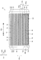
- first header tank 21 an internal space is formed in the first header tank 21, and the internal space communicates with all the tubes 15. Further, the first header tank 21 is provided with an inflow port 211 which communicates with the internal space of the first header tank 21 and into which cooling water flows.
- the inflow port 211 of the first header tank 21 is arranged so that a large amount of the cooling water is biased to the opening overlapping range 141 in the entire core portion 14 and flows.
- the outlet 221 of the second header tank 22 is also arranged in the same manner. That is, the inflow port 211 and the outflow port 221 of the present embodiment are arranged so that a large amount of the cooling water flows in the opening overlapping range 141 in the entire core portion 14 in a biased manner.
- the position of the upper end 141a of the opening overlapping range 141 in the vehicle vertical direction DR2 is within the width Ws occupied by the inlet 211 in the vehicle vertical direction DR2 (that is, the vertical width Ws of the inlet 211).
- the inflow port 211 is arranged so that a large amount of the cooling water flows in the opening overlapping range 141 in the entire core portion 14 in a biased manner.
- the fact that the inflow port 211 and the outflow port 221 are arranged so that a large amount of the cooling water flows in the opening overlapping range 141 in the entire core portion 14 can be said to be the following. .. That is, it can be said that the inflow port 211 and the outflow port 221 are located below the center position of the core portion 14 in the vehicle vertical direction DR2.
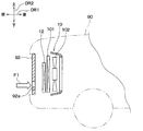
- the vehicle 95 of the comparative example is also provided with a front grill 96 corresponding to the front grill 92 of the present embodiment and a radiator 97 corresponding to the radiator 12 of the present embodiment.
- the front grill 96 in the comparative example of FIG. 3 is formed with a plurality of ventilation openings 96a so as to be entirely opened with respect to the core portion of the radiator 97.
- the ventilation opening 92a of the front grill 92 is only partially provided with respect to the core portion 14 of the radiator 12 on the front side of the radiator 12 in the vehicle front-rear direction DR1.
- the core portion 14 has an opening overlapping range 141 that overlaps the ventilation opening 92a of the front grill 92 on the rear side of the vehicle front-rear direction DR1 and is a partial range of the entire core portion 14.
- the inflow port 211 of the first header tank 21 is arranged so that a large amount of the cooling water flows toward the opening overlapping range 141 in the entire core portion 14 in a biased manner.
- the flow rate distribution of the cooling water in the core portion 14 is changed to the flow rate of the cooling water in the opening overlapping range 141 in accordance with the increase in the air volume of the opening overlapping range 141 in the air amount distribution of the air passing through the core portion 14.
- the distribution can be increased. Therefore, it is possible to increase the heat exchange rate in the heat exchange between the cooling water and the air, compared to the case where the flow rate distribution of the cooling water is uniform in the entire core portion 14, for example.
- the flow velocity of the cooling water in the overlapping opening range 141 becomes higher due to the uneven distribution of the flow rate of the cooling water. Therefore, in the opening overlapping range 141, the heat transfer coefficient between the tube 15 and the cooling water becomes high. This also makes it possible to increase the heat exchange rate in heat exchange between the cooling water and the air, as compared with the case where the flow rate distribution of the cooling water is uniform in the entire core portion 14.
- the size of the radiator 12 can be reduced, and the weight of the radiator 12 alone and the weight of the cooling water in the radiator 12 can be reduced to save power when the vehicle is traveling.
- the discharge flow rate of the water pump can be reduced to reduce the power consumption of the water pump, and it is possible to improve the running performance of the vehicle 90, especially the cruising range.
- the pressure of the cooling water also decreases, so it is possible to design with reduced pressure resistance in the piping for flowing the cooling water.
- the pressure resistance of the hose included in the piping for flowing the cooling water the thickness of the reserve tank can be reduced, and the cost of piping for the cooling water can be reduced. It is easy to reduce the amount.
- the inflow port 211 and the outflow port 221 are arranged so that the cooling water flows in a large amount in the opening overlapping range 141 in the entire core portion 14. Therefore, as compared with the case where the outlet 221 is arranged regardless of the flow rate distribution of the cooling water in the core portion 14, it is possible to flow a large amount of cooling water in the opening overlapping range 141.
- the inflow port 211 is within the stacking direction width Wrg of the opening overlapping range 141 in the tube stacking direction DRs. Therefore, since the inflow port 211 is arranged near the opening overlapping range 141, it is possible to bias the cooling water in the opening overlapping range 141 in the entire core portion 14 in a large amount.
- the arrangement of the inflow port 211 and the arrangement of the opening overlapping range 141 of the core portion 14 are the same as those in the first embodiment. However, the arrangement of the outlets 221 of this embodiment is different from that of the first embodiment.
- the outflow port 221 is located above the center position of the core portion 14 in the vehicle vertical direction DR2. Therefore, as in the first embodiment, the inflow port 211 is arranged so that a large amount of the cooling water is biased to the opening overlapping range 141 in the entire core portion 14 and flows. On the other hand, unlike the first embodiment, the outflow port 221 is not arranged so that a large amount of the cooling water is biased to the opening overlapping range 141 in the entire core portion 14 and flows.
- the present embodiment is the same as the first embodiment except that described above. Then, in the present embodiment, it is possible to obtain the same effect as that of the first embodiment, which is achieved by the configuration common to the first embodiment.
- the heat exchanger according to the present disclosure is the radiator 12 that heat-exchanges the running air and the cooling water, but the heat exchanger is not limited thereto.
- the heat medium flowing in the tube 15 may be a fluid other than cooling water, and the air that is heat-exchanged with the heat medium need not be traveling wind.
- the one direction in the present disclosure may not be the vehicle front-rear direction DR1.
- the vehicle 90 on which the radiator 12 is mounted is an electric vehicle, but is not limited to this.
- the vehicle 90 may be a hybrid vehicle or an engine vehicle that has an engine for traveling but does not have a motor for traveling.
- the capacitor 101 is arranged on the rear side of the radiator 12 in the vehicle front-rear direction DR1, but this is an example.
- the capacitor 101 may be arranged between the front grill 92 and the radiator 12 in the vehicle front-rear direction DR1. That is, the capacitor 101 may be disposed on the front side of the radiator 12 in the vehicle front-rear direction DR1. Furthermore, it can be considered that the capacitor 101 is not provided.
- the heat exchange is performed with respect to the wall body in which the ventilation opening through which the air flowing with one side of one direction as the air flow downstream side is formed is formed.
- the container is arranged on one side of the one direction.
- the first header tank is formed with an inflow port into which the heat medium flows, and the inflow port is arranged such that the heat medium flows mainly in the opening overlapping range in the entire core portion.
- the second header tank is formed with an outlet through which the heat medium flows out, and the heat inlet and the outlet are mostly concentrated in the overlapping area of the opening in the entire core portion. It is arranged to flow. With this configuration, it is possible to flow a large amount of the heat medium in the overlapping opening range as compared with the case where the outlets are arranged regardless of the flow rate distribution of the heat medium in the core portion.
- a plurality of tubes are stacked in a tube stacking direction that intersects the one direction. At least a part of the inflow port is within the width occupied by the opening overlapping range in the tube stacking direction.
- the heat exchanger is mounted on the vehicle.
- the heat medium is a liquid
- the one direction is a direction intersecting the vertical direction of the vehicle
- the plurality of tubes are stacked in the vertical direction.
- the opening overlapping range is formed as a range of the core portion that is biased downward in the vertical direction
- the inlet is located below the center position of the core portion in the vertical direction.
- the heat exchanger is mounted on the vehicle.
- the heat medium is a liquid
- the one direction is a direction intersecting the vertical direction of the vehicle
- the plurality of tubes are stacked in the vertical direction.
- the opening overlapping range is formed as a range that is biased downward in the vertical direction of the core portion, and the inlet and the outlet are located below in the vertical direction as compared with the center position of the core portion. ..
- the heat medium is biased to the opening overlapping range of the entire core portion due to the synergistic effect of the inlet and the outlet being arranged near the opening overlapping range and the gravity acting on the heat medium. It is possible to let it flow a lot.
- the heat exchanger is mounted on the vehicle.
- the heat medium is a liquid
- the one direction is a direction intersecting the vertical direction of the vehicle
- the plurality of tubes are stacked in the vertical direction.
- the opening overlapping range is formed as a range that is biased downward in the vertical direction of the core portion, and the position of the upper end of the opening overlapping range in the vertical direction is within the width occupied by the inlet in the vertical direction.
Landscapes
- Engineering & Computer Science (AREA)
- Mechanical Engineering (AREA)
- Transportation (AREA)
- Combustion & Propulsion (AREA)
- Chemical & Material Sciences (AREA)
- Physics & Mathematics (AREA)
- General Engineering & Computer Science (AREA)
- Thermal Sciences (AREA)
- Sustainable Energy (AREA)
- Power Engineering (AREA)
- Sustainable Development (AREA)
- Life Sciences & Earth Sciences (AREA)
- Geometry (AREA)
- Cooling, Air Intake And Gas Exhaust, And Fuel Tank Arrangements In Propulsion Units (AREA)
- Details Of Heat-Exchange And Heat-Transfer (AREA)
- Heat-Exchange Devices With Radiators And Conduit Assemblies (AREA)
- Electric Propulsion And Braking For Vehicles (AREA)
Abstract
La présente invention concerne un échangeur de chaleur disposé d'un côté dans une certaine direction par rapport à un corps de paroi dans lequel une ouverture de ventilation (92a), à travers laquelle un courant d'air passe, est formée, ledit côté dans ladite direction étant le côté aval du courant d'air. L'échangeur de chaleur comprend : un ensemble faisceau (14) ; un premier collecteur (21) ; un second collecteur (22). L'ensemble faisceau est conçu pour comprendre une pluralité de tubes (15) dans lesquels circule un agent caloporteur, chaque tube ayant une première extrémité (151) de tube et une seconde extrémité (152) de tube, et un échange de chaleur est effectué entre l'air ayant traversé l'ouverture de ventilation et l'agent caloporteur dans la pluralité de tubes. Les premières extrémités de tube sont reliées au premier collecteur, et une entrée d'écoulement (211), à travers laquelle coule l'agent caloporteur, est formée dans le premier collecteur. Les secondes extrémités de tube sont reliées au second collecteur pour faire circuler l'agent caloporteur. En outre, l'ensemble faisceau possède, dans une partie de tout l'ensemble faisceau, une plage de chevauchement d'ouverture (141) destinée à chevaucher l'ouverture de ventilation sur ledit côté dans ladite direction. L'entrée d'écoulement est disposée de sorte que l'agent caloporteur coule plus vers la région de chevauchement d'ouverture à l'intérieur de tout l'ensemble faisceau.
Priority Applications (2)
| Application Number | Priority Date | Filing Date | Title |
|---|---|---|---|
| CN202080012656.9A CN113412407A (zh) | 2019-02-06 | 2020-01-09 | 热交换器 |
| US17/369,647 US20210331579A1 (en) | 2019-02-06 | 2021-07-07 | Heat exchanger |
Applications Claiming Priority (2)
| Application Number | Priority Date | Filing Date | Title |
|---|---|---|---|
| JP2019-020001 | 2019-02-06 | ||
| JP2019020001A JP7255215B2 (ja) | 2019-02-06 | 2019-02-06 | 熱交換器 |
Related Child Applications (1)
| Application Number | Title | Priority Date | Filing Date |
|---|---|---|---|
| US17/369,647 Continuation US20210331579A1 (en) | 2019-02-06 | 2021-07-07 | Heat exchanger |
Publications (1)
| Publication Number | Publication Date |
|---|---|
| WO2020162096A1 true WO2020162096A1 (fr) | 2020-08-13 |
Family
ID=71947814
Family Applications (1)
| Application Number | Title | Priority Date | Filing Date |
|---|---|---|---|
| PCT/JP2020/000491 WO2020162096A1 (fr) | 2019-02-06 | 2020-01-09 | Échangeur de chaleur |
Country Status (4)
| Country | Link |
|---|---|
| US (1) | US20210331579A1 (fr) |
| JP (1) | JP7255215B2 (fr) |
| CN (1) | CN113412407A (fr) |
| WO (1) | WO2020162096A1 (fr) |
Families Citing this family (2)
| Publication number | Priority date | Publication date | Assignee | Title |
|---|---|---|---|---|
| USD957465S1 (en) * | 2020-10-16 | 2022-07-12 | Resource Intl Inc. | Intercooler for automotive applications |
| USD957461S1 (en) * | 2021-01-11 | 2022-07-12 | Resource Intl Inc. | Intercooler for automotive applications |
Citations (6)
| Publication number | Priority date | Publication date | Assignee | Title |
|---|---|---|---|---|
| JP2006015980A (ja) * | 2004-06-03 | 2006-01-19 | Denso Corp | 車両放熱用熱交換器の通風構造 |
| JP2006056421A (ja) * | 2004-08-20 | 2006-03-02 | Toyota Motor Corp | 車両用熱交換器 |
| JP3195404U (ja) * | 2014-10-31 | 2015-01-15 | 株式会社ヴァレオジャパン | 冷媒凝縮器 |
| WO2015178097A1 (fr) * | 2014-05-19 | 2015-11-26 | 三菱電機株式会社 | Dispositif de climatisation |
| EP2993418A2 (fr) * | 2014-08-14 | 2016-03-09 | LG Electronics Inc. | Climatiseur |
| WO2018173256A1 (fr) * | 2017-03-24 | 2018-09-27 | 三菱電機株式会社 | Dispositif de climatisation |
Family Cites Families (20)
| Publication number | Priority date | Publication date | Assignee | Title |
|---|---|---|---|---|
| JP2801373B2 (ja) * | 1990-07-02 | 1998-09-21 | サンデン株式会社 | 熱交換器 |
| US5205354A (en) * | 1992-01-28 | 1993-04-27 | Lesage Philip G | Vehicle radiator and method of making |
| US5257662A (en) * | 1992-03-27 | 1993-11-02 | The Allen Group Inc. | Heat exchanger assembly |
| US5570737A (en) * | 1993-10-07 | 1996-11-05 | Showa Aluminum Corporation | Heat exchanger |
| US20010004010A1 (en) * | 1998-02-09 | 2001-06-21 | Immanuel Halm | Heat exchanger having snap-on bracket |
| JP3577018B2 (ja) * | 2001-08-31 | 2004-10-13 | 本田技研工業株式会社 | 車両のフロントグリル周りの吸気構造 |
| JP2003089313A (ja) * | 2001-09-18 | 2003-03-25 | Denso Corp | 車両用空調装置 |
| JP2004098814A (ja) * | 2002-09-09 | 2004-04-02 | Fuji Heavy Ind Ltd | 車両の熱交換器取付構造 |
| KR100532053B1 (ko) * | 2002-12-31 | 2005-12-01 | 모딘코리아 유한회사 | 증발기 |
| US7260893B2 (en) * | 2004-01-09 | 2007-08-28 | Delphi Technologies, Inc. | Method of attaching a transmission oil cooler to an aluminum tank |
| CN100443812C (zh) * | 2006-07-12 | 2008-12-17 | 福建工程学院 | 回风调温轿车空调 |
| JP2011064388A (ja) * | 2009-09-17 | 2011-03-31 | Keihin Corp | 熱交換器に装着されるセンサの取付構造 |
| FR2975764B1 (fr) * | 2011-05-26 | 2013-07-12 | Valeo Systemes Thermiques | Boite collectrice, echangeur de chaleur comprenant ladite boite collectrice et procede de sertissage d'une telle boite. |
| WO2013123355A1 (fr) * | 2012-02-16 | 2013-08-22 | Delphi Technologies, Inc. | Adaptateur de plomberie de face pour un ensemble échangeur de chaleur |
| JP5626254B2 (ja) * | 2012-04-05 | 2014-11-19 | ダイキン工業株式会社 | 熱交換器 |
| JP6051935B2 (ja) * | 2013-02-26 | 2016-12-27 | 株式会社デンソー | 熱交換器 |
| JP6079477B2 (ja) * | 2013-06-28 | 2017-02-15 | 株式会社デンソー | 車両用空調装置 |
| US10005353B2 (en) * | 2014-10-29 | 2018-06-26 | Denso International America, Inc. | Mounting structure for in-tank oil cooler and radiator |
| JP6451387B2 (ja) * | 2015-02-17 | 2019-01-16 | 株式会社デンソー | 車両用送風装置 |
| CN206339110U (zh) * | 2016-11-04 | 2017-07-18 | 洛阳隆华传热节能股份有限公司 | 一种带有尖峰冷却功能的电力乏汽冷凝器 |
-
2019
- 2019-02-06 JP JP2019020001A patent/JP7255215B2/ja active Active
-
2020
- 2020-01-09 CN CN202080012656.9A patent/CN113412407A/zh active Pending
- 2020-01-09 WO PCT/JP2020/000491 patent/WO2020162096A1/fr active Application Filing
-
2021
- 2021-07-07 US US17/369,647 patent/US20210331579A1/en not_active Abandoned
Patent Citations (6)
| Publication number | Priority date | Publication date | Assignee | Title |
|---|---|---|---|---|
| JP2006015980A (ja) * | 2004-06-03 | 2006-01-19 | Denso Corp | 車両放熱用熱交換器の通風構造 |
| JP2006056421A (ja) * | 2004-08-20 | 2006-03-02 | Toyota Motor Corp | 車両用熱交換器 |
| WO2015178097A1 (fr) * | 2014-05-19 | 2015-11-26 | 三菱電機株式会社 | Dispositif de climatisation |
| EP2993418A2 (fr) * | 2014-08-14 | 2016-03-09 | LG Electronics Inc. | Climatiseur |
| JP3195404U (ja) * | 2014-10-31 | 2015-01-15 | 株式会社ヴァレオジャパン | 冷媒凝縮器 |
| WO2018173256A1 (fr) * | 2017-03-24 | 2018-09-27 | 三菱電機株式会社 | Dispositif de climatisation |
Also Published As
| Publication number | Publication date |
|---|---|
| CN113412407A (zh) | 2021-09-17 |
| JP7255215B2 (ja) | 2023-04-11 |
| JP2020125896A (ja) | 2020-08-20 |
| US20210331579A1 (en) | 2021-10-28 |
Similar Documents
| Publication | Publication Date | Title |
|---|---|---|
| US20080121385A1 (en) | Heat dissipation fin for heat exchangers | |
| JP2010121604A (ja) | 冷却システム | |
| WO2020162096A1 (fr) | Échangeur de chaleur | |
| JP2007232287A (ja) | 熱交換器および一体型熱交換器 | |
| JP2013002758A (ja) | 車両用冷却装置 | |
| JP2019081509A (ja) | 車両の冷却構造 | |
| JP2012001060A (ja) | 車両用熱交換器 | |
| ES2231594T3 (es) | Disposicion para la refrigeracion. | |
| JP2007186047A (ja) | 車両用熱交換器 | |
| JP6296439B2 (ja) | 車両用ラジエータ | |
| JP6589790B2 (ja) | 複合型熱交換器 | |
| WO2020170651A1 (fr) | Échangeur de chaleur composé | |
| JP2018034759A (ja) | 車両の前部構造 | |
| JP2006316747A (ja) | 車両用熱交換装置 | |
| JP2012117689A (ja) | 第2熱交換器の収納構造 | |
| WO2018037838A1 (fr) | Échangeur de chaleur de type combiné | |
| JP4276893B2 (ja) | 車両用熱交換装置 | |
| JP2018058531A (ja) | 冷却システム | |
| JP2006207944A (ja) | 熱交換器 | |
| JP2006266114A (ja) | 熱交換装置 | |
| JP2016102600A (ja) | 車載熱交換器 | |
| JP2006248333A (ja) | 車両用のクーリングシステム | |
| JP2019190685A (ja) | 冷却ユニット | |
| JP4420689B2 (ja) | 自動車のフロント構造 | |
| JP2014162369A (ja) | 車両用空調装置 |
Legal Events
| Date | Code | Title | Description |
|---|---|---|---|
| 121 | Ep: the epo has been informed by wipo that ep was designated in this application |
Ref document number: 20752605 Country of ref document: EP Kind code of ref document: A1 |
|
| NENP | Non-entry into the national phase |
Ref country code: DE |
|
| 122 | Ep: pct application non-entry in european phase |
Ref document number: 20752605 Country of ref document: EP Kind code of ref document: A1 |