WO2020162096A1 - Heat exchanger - Google Patents
Heat exchanger Download PDFInfo
- Publication number
- WO2020162096A1 WO2020162096A1 PCT/JP2020/000491 JP2020000491W WO2020162096A1 WO 2020162096 A1 WO2020162096 A1 WO 2020162096A1 JP 2020000491 W JP2020000491 W JP 2020000491W WO 2020162096 A1 WO2020162096 A1 WO 2020162096A1
- Authority
- WO
- WIPO (PCT)
- Prior art keywords
- core portion
- vertical direction
- vehicle
- heat
- heat exchanger
- Prior art date
Links
Images


Classifications
-
- B—PERFORMING OPERATIONS; TRANSPORTING
- B60—VEHICLES IN GENERAL
- B60K—ARRANGEMENT OR MOUNTING OF PROPULSION UNITS OR OF TRANSMISSIONS IN VEHICLES; ARRANGEMENT OR MOUNTING OF PLURAL DIVERSE PRIME-MOVERS IN VEHICLES; AUXILIARY DRIVES FOR VEHICLES; INSTRUMENTATION OR DASHBOARDS FOR VEHICLES; ARRANGEMENTS IN CONNECTION WITH COOLING, AIR INTAKE, GAS EXHAUST OR FUEL SUPPLY OF PROPULSION UNITS IN VEHICLES
- B60K11/00—Arrangement in connection with cooling of propulsion units
- B60K11/08—Air inlets for cooling; Shutters or blinds therefor
-
- B—PERFORMING OPERATIONS; TRANSPORTING
- B60—VEHICLES IN GENERAL
- B60K—ARRANGEMENT OR MOUNTING OF PROPULSION UNITS OR OF TRANSMISSIONS IN VEHICLES; ARRANGEMENT OR MOUNTING OF PLURAL DIVERSE PRIME-MOVERS IN VEHICLES; AUXILIARY DRIVES FOR VEHICLES; INSTRUMENTATION OR DASHBOARDS FOR VEHICLES; ARRANGEMENTS IN CONNECTION WITH COOLING, AIR INTAKE, GAS EXHAUST OR FUEL SUPPLY OF PROPULSION UNITS IN VEHICLES
- B60K11/00—Arrangement in connection with cooling of propulsion units
- B60K11/02—Arrangement in connection with cooling of propulsion units with liquid cooling
- B60K11/04—Arrangement or mounting of radiators, radiator shutters, or radiator blinds
-
- B—PERFORMING OPERATIONS; TRANSPORTING
- B60—VEHICLES IN GENERAL
- B60L—PROPULSION OF ELECTRICALLY-PROPELLED VEHICLES; SUPPLYING ELECTRIC POWER FOR AUXILIARY EQUIPMENT OF ELECTRICALLY-PROPELLED VEHICLES; ELECTRODYNAMIC BRAKE SYSTEMS FOR VEHICLES IN GENERAL; MAGNETIC SUSPENSION OR LEVITATION FOR VEHICLES; MONITORING OPERATING VARIABLES OF ELECTRICALLY-PROPELLED VEHICLES; ELECTRIC SAFETY DEVICES FOR ELECTRICALLY-PROPELLED VEHICLES
- B60L3/00—Electric devices on electrically-propelled vehicles for safety purposes; Monitoring operating variables, e.g. speed, deceleration or energy consumption
-
- B—PERFORMING OPERATIONS; TRANSPORTING
- B60—VEHICLES IN GENERAL
- B60L—PROPULSION OF ELECTRICALLY-PROPELLED VEHICLES; SUPPLYING ELECTRIC POWER FOR AUXILIARY EQUIPMENT OF ELECTRICALLY-PROPELLED VEHICLES; ELECTRODYNAMIC BRAKE SYSTEMS FOR VEHICLES IN GENERAL; MAGNETIC SUSPENSION OR LEVITATION FOR VEHICLES; MONITORING OPERATING VARIABLES OF ELECTRICALLY-PROPELLED VEHICLES; ELECTRIC SAFETY DEVICES FOR ELECTRICALLY-PROPELLED VEHICLES
- B60L50/00—Electric propulsion with power supplied within the vehicle
- B60L50/50—Electric propulsion with power supplied within the vehicle using propulsion power supplied by batteries or fuel cells
-
- F—MECHANICAL ENGINEERING; LIGHTING; HEATING; WEAPONS; BLASTING
- F01—MACHINES OR ENGINES IN GENERAL; ENGINE PLANTS IN GENERAL; STEAM ENGINES
- F01P—COOLING OF MACHINES OR ENGINES IN GENERAL; COOLING OF INTERNAL-COMBUSTION ENGINES
- F01P3/00—Liquid cooling
- F01P3/18—Arrangements or mounting of liquid-to-air heat-exchangers
-
- F—MECHANICAL ENGINEERING; LIGHTING; HEATING; WEAPONS; BLASTING
- F28—HEAT EXCHANGE IN GENERAL
- F28F—DETAILS OF HEAT-EXCHANGE AND HEAT-TRANSFER APPARATUS, OF GENERAL APPLICATION
- F28F9/00—Casings; Header boxes; Auxiliary supports for elements; Auxiliary members within casings
- F28F9/26—Arrangements for connecting different sections of heat-exchange elements, e.g. of radiators
- F28F9/262—Arrangements for connecting different sections of heat-exchange elements, e.g. of radiators for radiators
-
- F—MECHANICAL ENGINEERING; LIGHTING; HEATING; WEAPONS; BLASTING
- F28—HEAT EXCHANGE IN GENERAL
- F28D—HEAT-EXCHANGE APPARATUS, NOT PROVIDED FOR IN ANOTHER SUBCLASS, IN WHICH THE HEAT-EXCHANGE MEDIA DO NOT COME INTO DIRECT CONTACT
- F28D1/00—Heat-exchange apparatus having stationary conduit assemblies for one heat-exchange medium only, the media being in contact with different sides of the conduit wall, in which the other heat-exchange medium is a large body of fluid, e.g. domestic or motor car radiators
- F28D1/02—Heat-exchange apparatus having stationary conduit assemblies for one heat-exchange medium only, the media being in contact with different sides of the conduit wall, in which the other heat-exchange medium is a large body of fluid, e.g. domestic or motor car radiators with heat-exchange conduits immersed in the body of fluid
- F28D1/04—Heat-exchange apparatus having stationary conduit assemblies for one heat-exchange medium only, the media being in contact with different sides of the conduit wall, in which the other heat-exchange medium is a large body of fluid, e.g. domestic or motor car radiators with heat-exchange conduits immersed in the body of fluid with tubular conduits
- F28D1/053—Heat-exchange apparatus having stationary conduit assemblies for one heat-exchange medium only, the media being in contact with different sides of the conduit wall, in which the other heat-exchange medium is a large body of fluid, e.g. domestic or motor car radiators with heat-exchange conduits immersed in the body of fluid with tubular conduits the conduits being straight
- F28D1/0535—Heat-exchange apparatus having stationary conduit assemblies for one heat-exchange medium only, the media being in contact with different sides of the conduit wall, in which the other heat-exchange medium is a large body of fluid, e.g. domestic or motor car radiators with heat-exchange conduits immersed in the body of fluid with tubular conduits the conduits being straight the conduits having a non-circular cross-section
- F28D1/05366—Assemblies of conduits connected to common headers, e.g. core type radiators
-
- F—MECHANICAL ENGINEERING; LIGHTING; HEATING; WEAPONS; BLASTING
- F28—HEAT EXCHANGE IN GENERAL
- F28D—HEAT-EXCHANGE APPARATUS, NOT PROVIDED FOR IN ANOTHER SUBCLASS, IN WHICH THE HEAT-EXCHANGE MEDIA DO NOT COME INTO DIRECT CONTACT
- F28D21/00—Heat-exchange apparatus not covered by any of the groups F28D1/00 - F28D20/00
- F28D2021/0019—Other heat exchangers for particular applications; Heat exchange systems not otherwise provided for
- F28D2021/008—Other heat exchangers for particular applications; Heat exchange systems not otherwise provided for for vehicles
- F28D2021/0091—Radiators
-
- F—MECHANICAL ENGINEERING; LIGHTING; HEATING; WEAPONS; BLASTING
- F28—HEAT EXCHANGE IN GENERAL
- F28F—DETAILS OF HEAT-EXCHANGE AND HEAT-TRANSFER APPARATUS, OF GENERAL APPLICATION
- F28F1/00—Tubular elements; Assemblies of tubular elements
- F28F1/10—Tubular elements and assemblies thereof with means for increasing heat-transfer area, e.g. with fins, with projections, with recesses
- F28F1/12—Tubular elements and assemblies thereof with means for increasing heat-transfer area, e.g. with fins, with projections, with recesses the means being only outside the tubular element
- F28F1/126—Tubular elements and assemblies thereof with means for increasing heat-transfer area, e.g. with fins, with projections, with recesses the means being only outside the tubular element consisting of zig-zag shaped fins
-
- Y—GENERAL TAGGING OF NEW TECHNOLOGICAL DEVELOPMENTS; GENERAL TAGGING OF CROSS-SECTIONAL TECHNOLOGIES SPANNING OVER SEVERAL SECTIONS OF THE IPC; TECHNICAL SUBJECTS COVERED BY FORMER USPC CROSS-REFERENCE ART COLLECTIONS [XRACs] AND DIGESTS
- Y02—TECHNOLOGIES OR APPLICATIONS FOR MITIGATION OR ADAPTATION AGAINST CLIMATE CHANGE
- Y02T—CLIMATE CHANGE MITIGATION TECHNOLOGIES RELATED TO TRANSPORTATION
- Y02T10/00—Road transport of goods or passengers
- Y02T10/60—Other road transportation technologies with climate change mitigation effect
- Y02T10/70—Energy storage systems for electromobility, e.g. batteries
Definitions
- the fin 16 is, for example, a corrugated fin made of a thin plate made of an aluminum alloy.
- the fins 16 play a role of promoting heat exchange between the cooling water flowing in the tubes 15 and the air.
- first header tank 21 an internal space is formed in the first header tank 21, and the internal space communicates with all the tubes 15. Further, the first header tank 21 is provided with an inflow port 211 which communicates with the internal space of the first header tank 21 and into which cooling water flows.
- the inflow port 211 of the first header tank 21 is arranged so that a large amount of the cooling water is biased to the opening overlapping range 141 in the entire core portion 14 and flows.
- the outlet 221 of the second header tank 22 is also arranged in the same manner. That is, the inflow port 211 and the outflow port 221 of the present embodiment are arranged so that a large amount of the cooling water flows in the opening overlapping range 141 in the entire core portion 14 in a biased manner.
- the position of the upper end 141a of the opening overlapping range 141 in the vehicle vertical direction DR2 is within the width Ws occupied by the inlet 211 in the vehicle vertical direction DR2 (that is, the vertical width Ws of the inlet 211).
- the inflow port 211 is arranged so that a large amount of the cooling water flows in the opening overlapping range 141 in the entire core portion 14 in a biased manner.
- the fact that the inflow port 211 and the outflow port 221 are arranged so that a large amount of the cooling water flows in the opening overlapping range 141 in the entire core portion 14 can be said to be the following. .. That is, it can be said that the inflow port 211 and the outflow port 221 are located below the center position of the core portion 14 in the vehicle vertical direction DR2.
- the vehicle 95 of the comparative example is also provided with a front grill 96 corresponding to the front grill 92 of the present embodiment and a radiator 97 corresponding to the radiator 12 of the present embodiment.
- the front grill 96 in the comparative example of FIG. 3 is formed with a plurality of ventilation openings 96a so as to be entirely opened with respect to the core portion of the radiator 97.
- the ventilation opening 92a of the front grill 92 is only partially provided with respect to the core portion 14 of the radiator 12 on the front side of the radiator 12 in the vehicle front-rear direction DR1.
- the core portion 14 has an opening overlapping range 141 that overlaps the ventilation opening 92a of the front grill 92 on the rear side of the vehicle front-rear direction DR1 and is a partial range of the entire core portion 14.
- the inflow port 211 of the first header tank 21 is arranged so that a large amount of the cooling water flows toward the opening overlapping range 141 in the entire core portion 14 in a biased manner.
- the flow rate distribution of the cooling water in the core portion 14 is changed to the flow rate of the cooling water in the opening overlapping range 141 in accordance with the increase in the air volume of the opening overlapping range 141 in the air amount distribution of the air passing through the core portion 14.
- the distribution can be increased. Therefore, it is possible to increase the heat exchange rate in the heat exchange between the cooling water and the air, compared to the case where the flow rate distribution of the cooling water is uniform in the entire core portion 14, for example.
- the flow velocity of the cooling water in the overlapping opening range 141 becomes higher due to the uneven distribution of the flow rate of the cooling water. Therefore, in the opening overlapping range 141, the heat transfer coefficient between the tube 15 and the cooling water becomes high. This also makes it possible to increase the heat exchange rate in heat exchange between the cooling water and the air, as compared with the case where the flow rate distribution of the cooling water is uniform in the entire core portion 14.
- the size of the radiator 12 can be reduced, and the weight of the radiator 12 alone and the weight of the cooling water in the radiator 12 can be reduced to save power when the vehicle is traveling.
- the discharge flow rate of the water pump can be reduced to reduce the power consumption of the water pump, and it is possible to improve the running performance of the vehicle 90, especially the cruising range.
- the pressure of the cooling water also decreases, so it is possible to design with reduced pressure resistance in the piping for flowing the cooling water.
- the pressure resistance of the hose included in the piping for flowing the cooling water the thickness of the reserve tank can be reduced, and the cost of piping for the cooling water can be reduced. It is easy to reduce the amount.
- the inflow port 211 and the outflow port 221 are arranged so that the cooling water flows in a large amount in the opening overlapping range 141 in the entire core portion 14. Therefore, as compared with the case where the outlet 221 is arranged regardless of the flow rate distribution of the cooling water in the core portion 14, it is possible to flow a large amount of cooling water in the opening overlapping range 141.
- the inflow port 211 is within the stacking direction width Wrg of the opening overlapping range 141 in the tube stacking direction DRs. Therefore, since the inflow port 211 is arranged near the opening overlapping range 141, it is possible to bias the cooling water in the opening overlapping range 141 in the entire core portion 14 in a large amount.
- the arrangement of the inflow port 211 and the arrangement of the opening overlapping range 141 of the core portion 14 are the same as those in the first embodiment. However, the arrangement of the outlets 221 of this embodiment is different from that of the first embodiment.
- the outflow port 221 is located above the center position of the core portion 14 in the vehicle vertical direction DR2. Therefore, as in the first embodiment, the inflow port 211 is arranged so that a large amount of the cooling water is biased to the opening overlapping range 141 in the entire core portion 14 and flows. On the other hand, unlike the first embodiment, the outflow port 221 is not arranged so that a large amount of the cooling water is biased to the opening overlapping range 141 in the entire core portion 14 and flows.
- the present embodiment is the same as the first embodiment except that described above. Then, in the present embodiment, it is possible to obtain the same effect as that of the first embodiment, which is achieved by the configuration common to the first embodiment.
- the heat exchanger according to the present disclosure is the radiator 12 that heat-exchanges the running air and the cooling water, but the heat exchanger is not limited thereto.
- the heat medium flowing in the tube 15 may be a fluid other than cooling water, and the air that is heat-exchanged with the heat medium need not be traveling wind.
- the one direction in the present disclosure may not be the vehicle front-rear direction DR1.
- the vehicle 90 on which the radiator 12 is mounted is an electric vehicle, but is not limited to this.
- the vehicle 90 may be a hybrid vehicle or an engine vehicle that has an engine for traveling but does not have a motor for traveling.
- the capacitor 101 is arranged on the rear side of the radiator 12 in the vehicle front-rear direction DR1, but this is an example.
- the capacitor 101 may be arranged between the front grill 92 and the radiator 12 in the vehicle front-rear direction DR1. That is, the capacitor 101 may be disposed on the front side of the radiator 12 in the vehicle front-rear direction DR1. Furthermore, it can be considered that the capacitor 101 is not provided.
- the heat exchange is performed with respect to the wall body in which the ventilation opening through which the air flowing with one side of one direction as the air flow downstream side is formed is formed.
- the container is arranged on one side of the one direction.
- the first header tank is formed with an inflow port into which the heat medium flows, and the inflow port is arranged such that the heat medium flows mainly in the opening overlapping range in the entire core portion.
- the second header tank is formed with an outlet through which the heat medium flows out, and the heat inlet and the outlet are mostly concentrated in the overlapping area of the opening in the entire core portion. It is arranged to flow. With this configuration, it is possible to flow a large amount of the heat medium in the overlapping opening range as compared with the case where the outlets are arranged regardless of the flow rate distribution of the heat medium in the core portion.
- a plurality of tubes are stacked in a tube stacking direction that intersects the one direction. At least a part of the inflow port is within the width occupied by the opening overlapping range in the tube stacking direction.
- the heat exchanger is mounted on the vehicle.
- the heat medium is a liquid
- the one direction is a direction intersecting the vertical direction of the vehicle
- the plurality of tubes are stacked in the vertical direction.
- the opening overlapping range is formed as a range of the core portion that is biased downward in the vertical direction
- the inlet is located below the center position of the core portion in the vertical direction.
- the heat exchanger is mounted on the vehicle.
- the heat medium is a liquid
- the one direction is a direction intersecting the vertical direction of the vehicle
- the plurality of tubes are stacked in the vertical direction.
- the opening overlapping range is formed as a range that is biased downward in the vertical direction of the core portion, and the inlet and the outlet are located below in the vertical direction as compared with the center position of the core portion. ..
- the heat medium is biased to the opening overlapping range of the entire core portion due to the synergistic effect of the inlet and the outlet being arranged near the opening overlapping range and the gravity acting on the heat medium. It is possible to let it flow a lot.
- the heat exchanger is mounted on the vehicle.
- the heat medium is a liquid
- the one direction is a direction intersecting the vertical direction of the vehicle
- the plurality of tubes are stacked in the vertical direction.
- the opening overlapping range is formed as a range that is biased downward in the vertical direction of the core portion, and the position of the upper end of the opening overlapping range in the vertical direction is within the width occupied by the inlet in the vertical direction.
Abstract
This heat exchanger is disposed on one side in one direction relative to a wall body in which a ventilation opening (92a) through which flowing air passes is formed, the one side in the one direction being the downstream side of the flow of air. The heat exchanger comprises: a core unit (14); a first header tank (21); and a second header tank (22). The core unit is configured to include a plurality of tubes (15) in which a heat medium circulates, each tube having a tube first end (151) and a tube second end (152), and heat exchange is performed between the air which has passed through the ventilation opening and the heat medium in the plurality of tubes. The tube first ends are connected to the first header tank, and a flow inlet (211) through which the heat medium flows is formed in the first header tank. The tube second ends are connected to the second header tank to circulate the heat medium. Further, the core unit has, in a portion of the entire core unit, an opening overlap range (141) which overlaps with the ventilation opening on the one side in the one direction. The flow inlet is disposed so that the heat medium flows more toward the opening overlap region within the entire core unit.
Description
本出願は、2019年2月6日に出願された日本特許出願番号2019-20001号に基づくもので、ここにその記載内容が参照により組み入れられる。
This application is based on Japanese Patent Application No. 2019-20001 filed on February 6, 2019, the description of which is incorporated herein by reference.
本開示は、空気と熱媒体とを熱交換させる熱交換器に関するものである。
The present disclosure relates to a heat exchanger that exchanges heat between air and a heat medium.
例えば、この種の熱交換器である第1~第3空冷熱交換器を備えた冷却システムが、特許文献1に記載されている。その特許文献1によれば、第3空冷熱交換器のコア幅が第1空冷熱交換器のコア幅より狭くされている。これにより、第3空冷熱交換器は、第1空冷熱交換器の冷却水タンクの間に入り込むことが可能な構成となっている。そのため、冷却システムを冷却風方向に薄くしてコンパクトに構成できる。
For example, Patent Document 1 describes a cooling system including first to third air-cooling heat exchangers, which are heat exchangers of this type. According to Patent Document 1, the core width of the third air-cooling heat exchanger is narrower than the core width of the first air-cooling heat exchanger. As a result, the third air-cooling heat exchanger is configured to be able to enter between the cooling water tanks of the first air-cooling heat exchanger. Therefore, the cooling system can be made thin by being thin in the cooling air direction.
近年、電気自動車などの電動系の車種においては、走行時の空気抵抗低減を狙って、車両前方に設けられたフロントグリルのグリル開口が小さくなっている。このようにグリル開口が小さくなると、そのフロントグリルに対する空気流れ下流側に配置された熱交換器において、冷却風がコア部全体に満遍なく行き渡りにくくなる。
また、熱交換器において熱媒体が流入する流入口の設置場所によっては、熱交換器のコア部における熱媒体の流通に偏りが生じる場合がある。例えば、熱交換器のコア部において熱媒体の流量分布が、コア部を通過する冷却風の風量分布に対し大幅にずれている場合には、そうでない場合と比較して熱交換器の熱交換率が下がることになる。発明者の詳細な検討の結果、以上のようなことが見出された。 In recent years, in electric vehicle models such as electric vehicles, a grill opening of a front grill provided in front of the vehicle has become smaller in order to reduce air resistance during traveling. If the grille opening becomes smaller in this way, in the heat exchanger arranged on the downstream side of the air flow with respect to the front grille, it becomes difficult for the cooling air to spread evenly over the entire core portion.
Further, depending on the installation location of the inflow port into which the heat medium flows in the heat exchanger, the distribution of the heat medium in the core portion of the heat exchanger may be uneven. For example, if the flow rate distribution of the heat medium in the core part of the heat exchanger deviates significantly from the air flow rate distribution of the cooling air passing through the core part, the heat exchange of the heat exchanger will be greater than that in the other case. The rate will decrease. As a result of a detailed study by the inventor, the above has been found.
本開示は、上記に例示した事情等に鑑みてなされたものであり、コア部を通過する空気の風量分布に偏りがある場合に熱交換率を高めることが可能な熱交換器を提供することを目的とする。
The present disclosure has been made in view of the above-exemplified circumstances and the like, and provides a heat exchanger capable of increasing the heat exchange rate when there is a deviation in the air volume distribution of the air passing through the core portion. With the goal.
上記目的を達成するため、本開示の1つの観点によれば、熱交換器は、
一方向の一方側を空気流れ下流側として流れる空気が通過する通風開口が形成された壁体に対し、上記一方向の一方側に配置される熱交換器であって、
熱媒体が流通しチューブ一端とチューブ他端とを有する複数本のチューブを含んで構成され、通風開口を通過した空気と複数本のチューブ内の熱媒体とを熱交換させるコア部と、
チューブ一端が接続され、熱媒体が流入する流入口が形成された第1ヘッダタンクと、
チューブ他端が接続され、熱媒体が流通する第2ヘッダタンクとを備え、
コア部は、通風開口に対し上記一方向の一方側に重なる開口重複範囲を、コア部全体のうちの部分的な範囲として有し、
流入口は、熱媒体がコア部全体のうち開口重複範囲に偏って多く流れるように配置されている。 To achieve the above object, according to one aspect of the present disclosure, a heat exchanger includes:
A heat exchanger arranged on one side of the one direction with respect to a wall body in which a ventilation opening through which air flowing as one side of the one direction of the air flow passes is formed,
A core portion configured to include a plurality of tubes in which the heat medium flows and has a tube one end and a tube other end, and a heat exchange between the air that has passed through the ventilation openings and the heat medium in the plurality of tubes.
A first header tank in which one end of the tube is connected and an inflow port through which the heat medium flows is formed;
The other end of the tube is connected, and a second header tank through which a heat medium flows is provided,
The core portion has an opening overlapping range that overlaps one side of the one direction with respect to the ventilation opening as a partial range of the entire core portion,
The inflow port is arranged so that a large amount of the heat medium flows toward the opening overlapping range in the entire core portion.
このようにすれば、コア部を通過する空気の風量分布において開口重複範囲で空気の風量が多くなることに合わせて、コア部における熱媒体の流量分布を、開口重複範囲で熱媒体の流量が多くなる分布にすることができる。従って、例えばコア部全体で熱媒体の流量分布が均一である場合と比較して、熱媒体と空気との熱交換における熱交換率を高めることが可能である。
By doing so, the flow rate distribution of the heat medium in the core overlaps with the flow rate distribution of the heat medium in the overlapping opening range in accordance with the increase in the air flow rate in the overlapping opening range in the air volume distribution of the air passing through the core section. The distribution can be increased. Therefore, it is possible to increase the heat exchange rate in the heat exchange between the heat medium and air, as compared with the case where the flow rate distribution of the heat medium is uniform over the entire core portion.
なお、各構成要素等に付された括弧付きの参照符号は、その構成要素等と後述する実施形態に記載の具体的な構成要素等との対応関係の一例を示すものである。
Note that the reference numerals in parentheses attached to the respective constituent elements and the like indicate an example of a correspondence relationship between the constituent elements and the like and specific constituent elements and the like described in the embodiments described later.
以下、図面を参照しながら、各実施形態を説明する。なお、以下の各実施形態相互において、互いに同一もしくは均等である部分には、図中、同一符号を付してある。
Each embodiment will be described below with reference to the drawings. In each of the following embodiments, the same or equivalent parts are designated by the same reference numerals in the drawings.
(第1実施形態)
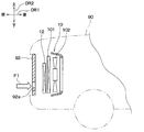
図1に示すように、本実施形態の熱交換器であるラジエータ12は、車両90に搭載される冷却システム10の一部を構成している。本実施形態において、その車両90は、エンジンを有さずモータで走行する電気自動車である。 (First embodiment)
As shown in FIG. 1, theradiator 12 which is the heat exchanger of the present embodiment constitutes a part of the cooling system 10 mounted on the vehicle 90. In the present embodiment, the vehicle 90 is an electric vehicle that does not have an engine and is driven by a motor.
図1に示すように、本実施形態の熱交換器であるラジエータ12は、車両90に搭載される冷却システム10の一部を構成している。本実施形態において、その車両90は、エンジンを有さずモータで走行する電気自動車である。 (First embodiment)
As shown in FIG. 1, the
図1の冷却システム10は、車両90の前方部分に設けられ、車両90が有するフロントグリル92に対し車両前後方向DR1の後側に配置されている。なお、図1および図2の各矢印DR1、DR2、DR3は、車両90の向きを示す。すなわち、図1の矢印DR1は車両前後方向DR1を示し、矢印DR2は車両上下方向DR2を示し、図2の矢印DR3は車両左右方向DR3すなわち車両幅方向DR3を示している。これらの方向DR1、DR2、DR3は互いに交差する方向、厳密に言えば互いに直交する方向である。
The cooling system 10 of FIG. 1 is provided in the front portion of the vehicle 90, and is disposed on the rear side of the vehicle front-rear direction DR1 with respect to the front grill 92 of the vehicle 90. Each arrow DR1, DR2, DR3 in FIGS. 1 and 2 indicates the direction of the vehicle 90. That is, the arrow DR1 in FIG. 1 indicates the vehicle front-rear direction DR1, the arrow DR2 indicates the vehicle vertical direction DR2, and the arrow DR3 in FIG. 2 indicates the vehicle left-right direction DR3, that is, the vehicle width direction DR3. These directions DR1, DR2, DR3 are directions intersecting with each other, or strictly speaking, directions orthogonal to each other.
フロントグリル92は、車両前方に向かって車外に露出するように配置された壁状の壁体である。フロントグリル92には、車両前後方向DR1に貫通した貫通孔である通風開口92aが形成されている。
The front grill 92 is a wall-shaped wall body that is arranged so as to be exposed to the outside of the vehicle toward the front of the vehicle. The front grill 92 has a ventilation opening 92a which is a through hole penetrating in the vehicle front-rear direction DR1.
従って、一方向の一方側を空気流れ下流側として流れる空気である走行風は、図1の矢印F1で示すように、フロントグリル92の通風開口92aを通過してフロントグリル92に対する空気流れ下流側へと流れる。その一方向とは車両前後方向DR1であり、一方向の一方側とは、車両前後方向DR1の後側である。なお、走行風は、フロントグリル92のうち通風開口92aを除いた部分を通過することはできない。
Therefore, the traveling wind, which is the air flowing on one side in one direction with the air flow downstream side, passes through the ventilation opening 92a of the front grill 92, as shown by the arrow F1 in FIG. Flows to. The one direction is the vehicle front-rear direction DR1 and one side of the one direction is the rear side of the vehicle front-rear direction DR1. The traveling wind cannot pass through the portion of the front grill 92 other than the ventilation openings 92a.
冷却システム10は、ラジエータ12のほかに、車室内の空調を行うための冷凍サイクル装置の一部を構成するコンデンサ101と、送風機102とを有している。ラジエータ12は、フロントグリル92に対し車両前後方向DR1の後側に配置されている。また、コンデンサ101は、ラジエータ12に対し車両前後方向DR1の後側に配置されている。また、送風機102は、コンデンサ101に対し車両前後方向DR1の後側に配置されている。
The cooling system 10 includes, in addition to the radiator 12, a condenser 101 that constitutes a part of a refrigeration cycle device for performing air conditioning in the vehicle compartment, and a blower 102. The radiator 12 is arranged on the rear side of the front grill 92 in the vehicle front-rear direction DR1. Further, the condenser 101 is arranged on the rear side of the radiator 12 in the vehicle front-rear direction DR1. The blower 102 is arranged on the rear side of the condenser 101 in the vehicle front-rear direction DR1.
送風機102は適宜作動させられる。送風機102は、その作動により、車両前後方向DR1の前側から後側へ空気流れを生じさせ、ラジエータ12とコンデンサ101とに空気を流す。
The blower 102 is operated appropriately. Due to its operation, the blower 102 causes an air flow from the front side to the rear side in the vehicle front-rear direction DR1, and causes the air to flow through the radiator 12 and the condenser 101.
本実施形態のラジエータ12は、車両90に搭載されたインバータやバッテリーを冷却するための低水温用ラジエータである。ラジエータ12内を流通する熱媒体は液体であり、本実施形態の熱媒体としては、冷却水が用いられる。ラジエータ12は、その冷却水と外気である走行風とを熱交換させることにより冷却水の熱を外気へ放出させる。従って、その走行風は、冷却水を冷却するための冷却風として機能する。ラジエータ12の冷却水の循環は、例えば不図示の電動ウォータポンプによって行われる。
The radiator 12 of the present embodiment is a low water temperature radiator for cooling an inverter and a battery mounted on the vehicle 90. The heat medium flowing through the radiator 12 is a liquid, and cooling water is used as the heat medium in this embodiment. The radiator 12 causes the heat of the cooling water to be released to the outside air by exchanging heat between the cooling water and the traveling wind that is the outside air. Therefore, the traveling wind functions as a cooling wind for cooling the cooling water. The cooling water of the radiator 12 is circulated by, for example, an electric water pump (not shown).
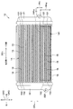
図2に示すように、ラジエータ12は、コア部14と第1ヘッダタンク21と第2ヘッダタンク22とを有している。
As shown in FIG. 2, the radiator 12 has a core portion 14, a first header tank 21, and a second header tank 22.
ラジエータ12のコア部14は、複数本のチューブ15と複数のフィン16とを含んで構成されている。コア部14は、ラジエータ12のうち、空気(例えば走行風)と複数本のチューブ15内の冷却水とを熱交換させる部分である。
The core portion 14 of the radiator 12 is configured to include a plurality of tubes 15 and a plurality of fins 16. The core portion 14 is a portion of the radiator 12 that exchanges heat between air (for example, traveling wind) and the cooling water in the plurality of tubes 15.
複数本のチューブ15と複数のフィン16は、チューブ積層方向DRsに交互に積層されるように配置されている。そのチューブ積層方向DRsは、本実施形態では車両上下方向DR2に一致している。
The plurality of tubes 15 and the plurality of fins 16 are arranged so as to be alternately stacked in the tube stacking direction DRs. The tube stacking direction DRs corresponds to the vehicle vertical direction DR2 in this embodiment.
複数本のチューブ15はそれぞれ、例えば扁平断面形状を有するアルミニウム合金製の管であり、チューブ延伸方向DRtに延伸している。そのチューブ延伸方向DRtは、本実施形態では車両幅方向DR3に一致している。
Each of the plurality of tubes 15 is, for example, an aluminum alloy tube having a flat cross-sectional shape, and is stretched in the tube stretching direction DRt. The tube extending direction DRt corresponds to the vehicle width direction DR3 in the present embodiment.
チューブ15の内部には冷却水が流通し、その冷却水と熱交換させられる空気(例えば、走行風)は、チューブ15の相互間に流通する。そして、チューブ15は、チューブ延伸方向DRtの一方側(すなわち、車両幅方向DR3の右側)に位置するチューブ一端151と、チューブ延伸方向DRtの他方側(すなわち、車両幅方向DR3の左側)に位置するチューブ他端152とを有している。
Cooling water flows inside the tubes 15, and air (for example, running wind) that is heat-exchanged with the cooling water flows between the tubes 15. The tube 15 is located on one side of the tube extending direction DRt (that is, on the right side in the vehicle width direction DR3) and on the other side of the tube extending direction DRt (that is, on the left side in the vehicle width direction DR3). The other end 152 of the tube.
フィン16は、例えば、アルミニウム合金製の薄板から成るコルゲートフィンである。フィン16は、チューブ15内を流通する冷却水と空気との熱交換を促進する役割を果たす。
The fin 16 is, for example, a corrugated fin made of a thin plate made of an aluminum alloy. The fins 16 play a role of promoting heat exchange between the cooling water flowing in the tubes 15 and the air.
コア部14は、このような構成により、フロントグリル92の通風開口92a(図1参照)を通過した空気(例えば走行風)と複数本のチューブ15内の冷却水とを熱交換させる。
With such a configuration, the core portion 14 exchanges heat between the air (eg, traveling wind) that has passed through the ventilation openings 92a (see FIG. 1) of the front grill 92 and the cooling water in the plurality of tubes 15.
第1ヘッダタンク21は、コア部14に対しチューブ延伸方向DRtの一方側(すなわち、車両幅方向DR3の右側)に配置されている。第1ヘッダタンク21には、全てのチューブ15のチューブ一端151がそれぞれ接続されている。第1ヘッダタンク21は、チューブ積層方向DRsに延びた形状を有している。
The first header tank 21 is arranged on one side of the core portion 14 in the tube extending direction DRt (that is, on the right side in the vehicle width direction DR3). The tube ends 151 of all the tubes 15 are connected to the first header tank 21, respectively. The first header tank 21 has a shape extending in the tube stacking direction DRs.
また、第1ヘッダタンク21には内部空間が形成されており、その内部空間は全てのチューブ15と連通している。また、第1ヘッダタンク21には、その第1ヘッダタンク21の内部空間に連通し冷却水が流入する流入口211が形成されている。
Also, an internal space is formed in the first header tank 21, and the internal space communicates with all the tubes 15. Further, the first header tank 21 is provided with an inflow port 211 which communicates with the internal space of the first header tank 21 and into which cooling water flows.
第1ヘッダタンク21の流入口211には、ラジエータ12へ冷却水を供給する冷却水供給管が連結される。従って、第1ヘッダタンク21の内部空間には冷却水が流通し、第1ヘッダタンク21は、冷却水供給管から供給された冷却水を各チューブ15へ分配する役割を果たす。
A cooling water supply pipe for supplying cooling water to the radiator 12 is connected to the inflow port 211 of the first header tank 21. Therefore, the cooling water flows in the internal space of the first header tank 21, and the first header tank 21 serves to distribute the cooling water supplied from the cooling water supply pipe to the tubes 15.
第2ヘッダタンク22は、コア部14に対しチューブ延伸方向DRtの他方側(すなわち、車両幅方向DR3の左側)に配置されている。第2ヘッダタンク22には、全てのチューブ15のチューブ他端152がそれぞれ接続されている。第2ヘッダタンク22は、チューブ積層方向DRsに延びた形状を有している。
The second header tank 22 is arranged on the other side of the core portion 14 in the tube extending direction DRt (that is, on the left side in the vehicle width direction DR3). The tube other ends 152 of all the tubes 15 are connected to the second header tank 22, respectively. The second header tank 22 has a shape extending in the tube stacking direction DRs.
また、第2ヘッダタンク22には内部空間が形成されており、その内部空間は全てのチューブ15と連通している。また、第2ヘッダタンク22には、その第2ヘッダタンク22の内部空間に連通し冷却水が流出する流出口221が形成されている。その流出口221は、車両上下方向DR2において、流入口211に対し下側に配置されている。
Also, an internal space is formed in the second header tank 22, and the internal space communicates with all the tubes 15. Further, the second header tank 22 is formed with an outlet 221 that communicates with the internal space of the second header tank 22 and through which cooling water flows out. The outflow port 221 is arranged below the inflow port 211 in the vehicle vertical direction DR2.
第2ヘッダタンク22の流出口221には、ラジエータ12から冷却水を流出させる冷却水流出管が連結される。従って、第2ヘッダタンク22の内部空間には冷却水が流通し、第2ヘッダタンク22は、各チューブ15から流出した冷却水を集合させてラジエータ12の外部へ流出させる役割を果たす。
A cooling water outflow pipe for outflowing the cooling water from the radiator 12 is connected to the outlet 221 of the second header tank 22. Therefore, the cooling water flows in the internal space of the second header tank 22, and the second header tank 22 plays a role of collecting the cooling water flowing out from each tube 15 and flowing it to the outside of the radiator 12.
ラジエータ12が上述のように構成されることにより、流入口211から第1ヘッダタンク21内へ流入した熱媒体としての冷却水は、第1ヘッダタンク21にて各チューブ15へ分配される。その分配された冷却水は、各チューブ15において第1ヘッダタンク21側から第2ヘッダタンク22側へ流れ、第2ヘッダタンク22にて集合する。そして、流出口221からラジエータ12の外部(具体的には、冷却水流出管)へ流出する。
With the radiator 12 configured as described above, the cooling water as the heat medium that has flowed into the first header tank 21 from the inflow port 211 is distributed to the tubes 15 in the first header tank 21. The distributed cooling water flows from the first header tank 21 side to the second header tank 22 side in each tube 15 and collects in the second header tank 22. Then, it flows out from the outlet 221 to the outside of the radiator 12 (specifically, a cooling water outflow pipe).
ここで、図1および図2に示すように、ラジエータ12に対する車両前後方向DR1の前側にはフロントグリル92が配置されている。そのため、コア部14は、フロントグリル92の通風開口92aに対し車両前後方向DR1の後側に重なる開口重複範囲141を、コア部14全体のうちの部分的な範囲として有している。この開口重複範囲141は、別言すれば、ラジエータ12に対して通風開口92aを車両前後方向DR1に沿って投影して得られる投影範囲である。例えば本実施形態では、開口重複範囲141は、コア部14のうち車両上下方向DR2での下側に偏った範囲として形成されている。図2では、開口重複範囲141は、車両上下方向DR2において、コア部14の中心位置よりも下側に形成されている。
Here, as shown in FIG. 1 and FIG. 2, a front grill 92 is arranged on the front side of the radiator 12 in the vehicle front-rear direction DR1. Therefore, the core portion 14 has an opening overlapping range 141 overlapping the rear side of the vehicle front-rear direction DR1 with respect to the ventilation opening 92a of the front grill 92 as a partial range of the entire core portion 14. In other words, the opening overlapping range 141 is a projection range obtained by projecting the ventilation opening 92a on the radiator 12 along the vehicle front-rear direction DR1. For example, in this embodiment, the opening overlapping range 141 is formed as a range of the core portion 14 that is biased downward in the vehicle vertical direction DR2. In FIG. 2, the opening overlapping range 141 is formed below the center position of the core portion 14 in the vehicle vertical direction DR2.
このように開口重複範囲141がコア部14全体のうちの部分的な範囲であるので、フロントグリル92の通風開口92aを通った走行風はコア部14全体に満遍なく拡がって通過するのではなく、コア部14における走行風の風量に偏りが生じる。具体的に、その通風開口92aを通った走行風は、コア部14のうち開口重複範囲141に偏って多く流れる。
Since the opening overlapping range 141 is a partial range of the entire core portion 14 as described above, the traveling wind passing through the ventilation opening 92a of the front grill 92 does not spread evenly over the entire core portion 14 and passes therethrough. The air volume of the traveling wind in the core portion 14 is uneven. Specifically, a large amount of traveling wind that has passed through the ventilation opening 92a is biased toward the opening overlapping range 141 of the core portion 14.
そこで、第1ヘッダタンク21の流入口211は、冷却水がコア部14全体のうち開口重複範囲141に偏って多く流れるように配置されている。そして、第2ヘッダタンク22の流出口221も、それと同様に配置されている。すなわち、本実施形態の流入口211と流出口221は、冷却水がコア部14全体のうち開口重複範囲141に偏って多く流れるように配置されている。
Therefore, the inflow port 211 of the first header tank 21 is arranged so that a large amount of the cooling water is biased to the opening overlapping range 141 in the entire core portion 14 and flows. The outlet 221 of the second header tank 22 is also arranged in the same manner. That is, the inflow port 211 and the outflow port 221 of the present embodiment are arranged so that a large amount of the cooling water flows in the opening overlapping range 141 in the entire core portion 14 in a biased manner.
要するに、第1ヘッダタンク21における流入口211の設置位置は、冷却水がコア部14全体のうち開口重複範囲141に偏って多く流れる位置になっている。そして、第2ヘッダタンク22における流出口221の設置位置も、冷却水がコア部14全体のうち開口重複範囲141に偏って多く流れる位置になっている。
In short, the installation position of the inflow port 211 in the first header tank 21 is such that a large amount of cooling water flows toward the opening overlapping range 141 in the entire core portion 14 in a biased manner. Further, the installation position of the outflow port 221 in the second header tank 22 is also a position where the cooling water flows mainly in the opening overlapping range 141 in the entire core portion 14 in a biased manner.
具体的に言うと、流入口211のうちの少なくとも一部は、チューブ積層方向DRsにおいて開口重複範囲141が占める幅Wrg(すなわち、開口重複範囲141の積層方向幅Wrg)内に入っている。これにより、流入口211は、上記のように、冷却水がコア部14全体のうち開口重複範囲141に偏って多く流れるように配置されていることになる。
Specifically, at least a part of the inflow port 211 is within the width Wrg occupied by the opening overlapping range 141 in the tube stacking direction DRs (that is, the width Wrg of the opening overlapping range 141 in the stacking direction). As a result, as described above, the inflow port 211 is arranged so that a large amount of the cooling water flows in the opening overlapping range 141 in the entire core portion 14 in a biased manner.
従って、冷却水がコア部14全体のうち開口重複範囲141に偏って多く流れるように流入口211が配置されていることとは、本実施形態では次のことであると言える。すなわち、そのこととは、流入口211のうちの少なくとも一部が、チューブ積層方向DRsにおいて開口重複範囲141の積層方向幅Wrg内に入っていることであると言える。図2では、流入口211の全部ではなく一部が、開口重複範囲141の積層方向幅Wrg内に入っている。
Therefore, in the present embodiment, it can be said that the inflow port 211 is arranged so that the cooling water is concentrated in the opening overlapping range 141 in the entire core portion 14 and flows in large amounts. That is, it can be said that at least part of the inflow port 211 is within the stacking direction width Wrg of the opening overlapping range 141 in the tube stacking direction DRs. In FIG. 2, not all of the inflow port 211 but part of the inflow port 211 is within the stacking direction width Wrg of the opening overlapping range 141.
また、別言すれば、車両上下方向DR2における開口重複範囲141の上端141aの位置は、流入口211が車両上下方向DR2に占める幅Ws(すなわち、流入口211の上下幅Ws)内に入っている。これにより、流入口211は、上記のように、冷却水がコア部14全体のうち開口重複範囲141に偏って多く流れるように配置されていることになる。
In other words, the position of the upper end 141a of the opening overlapping range 141 in the vehicle vertical direction DR2 is within the width Ws occupied by the inlet 211 in the vehicle vertical direction DR2 (that is, the vertical width Ws of the inlet 211). There is. As a result, as described above, the inflow port 211 is arranged so that a large amount of the cooling water flows in the opening overlapping range 141 in the entire core portion 14 in a biased manner.
従って、冷却水がコア部14全体のうち開口重複範囲141に偏って多く流れるように流入口211が配置されていることとは、本実施形態では次のことであるとも言える。すなわち、そのこととは、車両上下方向DR2における開口重複範囲141の上端141aの位置が流入口211の上下幅Ws内に入っていることであるとも言える。
Therefore, it can be said that, in the present embodiment, the fact that the inlet 211 is arranged so that a large amount of the cooling water flows in the opening overlapping range 141 in the entire core portion 14 in a biased manner. That is, it can be said that the position of the upper end 141a of the opening overlapping range 141 in the vehicle vertical direction DR2 is within the vertical width Ws of the inflow port 211.
また、流入口211と流出口221との両方に着目すると、流入口211と流出口221は、車両上下方向DR2において、コア部14の中心位置と比較して下側に位置している。これにより、流入口211および流出口221は、上記のように、冷却水がコア部14全体のうち開口重複範囲141に偏って多く流れるように配置されていることになる。
Further, focusing on both the inflow port 211 and the outflow port 221, the inflow port 211 and the outflow port 221 are located below the center position of the core portion 14 in the vehicle vertical direction DR2. As a result, the inflow port 211 and the outflow port 221 are arranged such that the cooling water is biased to the opening overlapping range 141 in the entire core portion 14 in a large amount, as described above.
従って、冷却水がコア部14全体のうち開口重複範囲141に偏って多く流れるように流入口211と流出口221とが配置されていることとは、本実施形態では次のことであると言える。すなわち、そのこととは、流入口211と流出口221とが、車両上下方向DR2において、コア部14の中心位置と比較して下側に位置していることであると言える。
Therefore, in the present embodiment, the fact that the inflow port 211 and the outflow port 221 are arranged so that a large amount of the cooling water flows in the opening overlapping range 141 in the entire core portion 14 can be said to be the following. .. That is, it can be said that the inflow port 211 and the outflow port 221 are located below the center position of the core portion 14 in the vehicle vertical direction DR2.
ここで、本実施形態と比較するための図3の比較例について説明する。その図3に示すように、比較例の車両95でも、本実施形態のフロントグリル92に対応するフロントグリル96と、本実施形態のラジエータ12に対応するラジエータ97とが設けられている。但し、本実施形態とは異なり、図3の比較例におけるフロントグリル96には、ラジエータ97のコア部に対し全体的に開口するするように複数の通風開口96aが形成されている。
Here, a comparative example of FIG. 3 for comparison with the present embodiment will be described. As shown in FIG. 3, the vehicle 95 of the comparative example is also provided with a front grill 96 corresponding to the front grill 92 of the present embodiment and a radiator 97 corresponding to the radiator 12 of the present embodiment. However, unlike the present embodiment, the front grill 96 in the comparative example of FIG. 3 is formed with a plurality of ventilation openings 96a so as to be entirely opened with respect to the core portion of the radiator 97.
これに対し、本実施形態では図1および図2に示すように、フロントグリル92の通風開口92aは、ラジエータ12に対する車両前後方向DR1の前側において、ラジエータ12のコア部14に対し部分的にしか開口していない。そのため、本実施形態のラジエータ12において、コア部14は、フロントグリル92の通風開口92aに対し車両前後方向DR1の後側に重なる開口重複範囲141を、コア部14全体のうちの部分的な範囲として有している。そして、第1ヘッダタンク21の流入口211は、冷却水がコア部14全体のうち開口重複範囲141に偏って多く流れるように配置されている。
On the other hand, in the present embodiment, as shown in FIGS. 1 and 2, the ventilation opening 92a of the front grill 92 is only partially provided with respect to the core portion 14 of the radiator 12 on the front side of the radiator 12 in the vehicle front-rear direction DR1. Not open. Therefore, in the radiator 12 of the present embodiment, the core portion 14 has an opening overlapping range 141 that overlaps the ventilation opening 92a of the front grill 92 on the rear side of the vehicle front-rear direction DR1 and is a partial range of the entire core portion 14. Have as. Then, the inflow port 211 of the first header tank 21 is arranged so that a large amount of the cooling water flows toward the opening overlapping range 141 in the entire core portion 14 in a biased manner.
これにより、コア部14を通過する空気の風量分布において開口重複範囲141で空気の風量が多くなることに合わせて、コア部14における冷却水の流量分布を、開口重複範囲141で冷却水の流量が多くなる分布にすることができる。従って、例えばコア部14全体で冷却水の流量分布が均一である場合と比較して、冷却水と空気との熱交換における熱交換率を高めることが可能である。
As a result, the flow rate distribution of the cooling water in the core portion 14 is changed to the flow rate of the cooling water in the opening overlapping range 141 in accordance with the increase in the air volume of the opening overlapping range 141 in the air amount distribution of the air passing through the core portion 14. The distribution can be increased. Therefore, it is possible to increase the heat exchange rate in the heat exchange between the cooling water and the air, compared to the case where the flow rate distribution of the cooling water is uniform in the entire core portion 14, for example.
また、コア部14全体で冷却水の流量分布が均一である場合と比較して、上記の冷却水の流量分布の偏りにより、開口重複範囲141における冷却水の流速は高くなる。そのため、開口重複範囲141では、チューブ15と冷却水との間の熱伝達率が高くなる。このことによっても、コア部14全体で冷却水の流量分布が均一である場合と比較して、冷却水と空気との熱交換における熱交換率を高めることが可能である。
Further, compared to the case where the flow rate distribution of the cooling water is uniform over the entire core portion 14, the flow velocity of the cooling water in the overlapping opening range 141 becomes higher due to the uneven distribution of the flow rate of the cooling water. Therefore, in the opening overlapping range 141, the heat transfer coefficient between the tube 15 and the cooling water becomes high. This also makes it possible to increase the heat exchange rate in heat exchange between the cooling water and the air, as compared with the case where the flow rate distribution of the cooling water is uniform in the entire core portion 14.
このようにラジエータ12の熱交換率が高まることによって、次に示すような効果が得られる。例えば、ラジエータ12の体格を小さくすることができ、ラジエータ12単体での軽量化およびラジエータ12内にある冷却水の軽量化により、車両走行時の省動力化を図ることができる。また、冷却水を循環させるウォータポンプの体格拡大を抑え、そのウォータポンプの軽量化を図ることができ、延いては車両走行時の省動力化を図ることができる。また、ウォータポンプの吐出流量を下げてそのウォータポンプの消費電力を抑えることができ、車両90の走行性能の向上、特に航続距離の向上を図ることが可能である。
By increasing the heat exchange rate of the radiator 12 in this way, the following effects can be obtained. For example, the size of the radiator 12 can be reduced, and the weight of the radiator 12 alone and the weight of the cooling water in the radiator 12 can be reduced to save power when the vehicle is traveling. In addition, it is possible to suppress the expansion of the size of the water pump that circulates the cooling water, to reduce the weight of the water pump, and to reduce the power consumption when the vehicle is traveling. In addition, the discharge flow rate of the water pump can be reduced to reduce the power consumption of the water pump, and it is possible to improve the running performance of the vehicle 90, especially the cruising range.
また、ウォータポンプの吐出流量低下は冷却水の圧力低下になるので、冷却水を流す配管等における耐圧を下げた設計を行うことが可能になる。そのように耐圧を下げた設計を行うことにより、冷却水を流す配管等に含まれるホースの耐圧引下げやリザーブタンクの板厚の薄肉化を図り、延いては、冷却水を流す配管等においてコスト低減を図りやすくなる。
Also, as the discharge flow rate of the water pump decreases, the pressure of the cooling water also decreases, so it is possible to design with reduced pressure resistance in the piping for flowing the cooling water. By lowering the pressure resistance in such a way, the pressure resistance of the hose included in the piping for flowing the cooling water, the thickness of the reserve tank can be reduced, and the cost of piping for the cooling water can be reduced. It is easy to reduce the amount.
また、本実施形態によれば、流入口211と流出口221は、冷却水がコア部14全体のうち開口重複範囲141に偏って多く流れるように配置されている。従って、コア部14における冷却水の流量分布とは無関係に流出口221が配置される場合と比較して、多くの冷却水を開口重複範囲141に流すことが可能である。
Further, according to the present embodiment, the inflow port 211 and the outflow port 221 are arranged so that the cooling water flows in a large amount in the opening overlapping range 141 in the entire core portion 14. Therefore, as compared with the case where the outlet 221 is arranged regardless of the flow rate distribution of the cooling water in the core portion 14, it is possible to flow a large amount of cooling water in the opening overlapping range 141.
また、本実施形態によれば、流入口211のうちの少なくとも一部は、チューブ積層方向DRsにおいて開口重複範囲141の積層方向幅Wrg内に入っている。従って、流入口211が開口重複範囲141の近くに配置されるので、コア部14全体のうち開口重複範囲141に冷却水を偏らせて多く流すことが可能である。
Further, according to the present embodiment, at least part of the inflow port 211 is within the stacking direction width Wrg of the opening overlapping range 141 in the tube stacking direction DRs. Therefore, since the inflow port 211 is arranged near the opening overlapping range 141, it is possible to bias the cooling water in the opening overlapping range 141 in the entire core portion 14 in a large amount.
また、本実施形態によれば、開口重複範囲141は、コア部14のうち車両上下方向DR2での下側に偏った範囲として形成されている。そして、流入口211は、車両上下方向DR2において、コア部14の中心位置と比較して下側に位置している。従って、流入口211が開口重複範囲141の近くに配置されることと、冷却水に作用する重力との相乗効果により、コア部14全体のうち開口重複範囲141に冷却水を偏らせて多く流すことが可能である。
Further, according to the present embodiment, the opening overlapping range 141 is formed as a range of the core portion 14 that is biased downward in the vehicle vertical direction DR2. The inflow port 211 is located below the center position of the core portion 14 in the vehicle vertical direction DR2. Therefore, due to the synergistic effect of the inflow port 211 being arranged near the overlapping opening range 141 and the gravity acting on the cooling water, a large amount of the cooling water is biased to the overlapping opening range 141 in the entire core portion 14. It is possible.
また、本実施形態によれば、流入口211だけでなく流出口221も、車両上下方向DR2において、コア部14の中心位置と比較して下側に位置している。従って、流入口211と流出口221とが開口重複範囲141の近くに配置されることと、冷却水に作用する重力との相乗効果により、コア部14全体のうち開口重複範囲141に冷却水を偏らせて多く流すことが可能である。
Further, according to the present embodiment, not only the inflow port 211 but also the outflow port 221 is located below the center position of the core portion 14 in the vehicle vertical direction DR2. Therefore, due to the synergistic effect of the inflow port 211 and the outflow port 221 being arranged near the opening overlapping range 141 and the gravity acting on the cooling water, the cooling water is supplied to the opening overlapping range 141 of the entire core portion 14. It is possible to bias and flow a large amount.
また、流入口211の位置と流出口221の位置との上下方向差が縮小するので、それに伴ってコア部14の開口重複範囲141における冷却水の流速が高まり、開口重複範囲141においてチューブ15と冷却水との間の熱伝達率が高くなる。これによって、ラジエータ12での冷却水と空気との熱交換における熱交換率が高くなるという作用効果を得ることが可能である。特に、本実施形態では開口重複範囲141がコア部14のうち車両上下方向DR2での下側に偏った範囲として形成されているので、重力の兼ね合いから上記作用効果は顕著である。
Further, since the vertical difference between the position of the inflow port 211 and the position of the outflow port 221 decreases, the flow velocity of the cooling water in the opening overlapping range 141 of the core portion 14 increases accordingly, and the tube 15 in the opening overlapping range 141 becomes The heat transfer coefficient with the cooling water is high. As a result, it is possible to obtain the effect of increasing the heat exchange rate in the heat exchange between the cooling water and the air in the radiator 12. In particular, in the present embodiment, the opening overlapping range 141 is formed in the core portion 14 as a range that is biased downward in the vehicle up-down direction DR2.
また、本実施形態によれば、開口重複範囲141の上端141aの位置は、車両上下方向DR2において流入口211の上下幅Ws内に入っている。従って、流入口211が開口重複範囲141の近くに配置されることと、冷却水に作用する重力との相乗効果により、コア部14全体のうち開口重複範囲141に冷却水を偏らせて多く流すことが可能である。そして、流入口211から入った冷却水を、開口重複範囲141の上側部分から重力を利用して開口重複範囲141の全体に行き渡らせ易いというメリットがある。
Further, according to the present embodiment, the position of the upper end 141a of the opening overlapping range 141 is within the vertical width Ws of the inflow port 211 in the vehicle vertical direction DR2. Therefore, due to the synergistic effect of the inflow port 211 being arranged near the overlapping opening range 141 and the gravity acting on the cooling water, a large amount of the cooling water is biased to the overlapping opening range 141 in the entire core portion 14. It is possible. Then, there is an advantage that the cooling water entering from the inflow port 211 can be easily spread over the entire opening overlapping range 141 from the upper portion of the opening overlapping range 141 by using gravity.
(第2実施形態)
次に、第2実施形態について説明する。本実施形態では、前述の第1実施形態と異なる点を主として説明する。また、前述の実施形態と同一または均等な部分については省略または簡略化して説明する。このことは、後述の実施形態の説明においても同様である。 (Second embodiment)
Next, a second embodiment will be described. In the present embodiment, points different from the first embodiment described above will be mainly described. Further, the same or equivalent portions as those of the above-described embodiment will be omitted or simplified for the description. This also applies to the description of the embodiments described later.
図4に示すように、本実施形態のラジエータ12において流入口211の配置、およびコア部14の開口重複範囲141の配置は、第1実施形態と同じである。しかし、本実施形態の流出口221の配置は第1実施形態と異なっている。
As shown in FIG. 4, in the radiator 12 of the present embodiment, the arrangement of the inflow port 211 and the arrangement of the opening overlapping range 141 of the core portion 14 are the same as those in the first embodiment. However, the arrangement of the outlets 221 of this embodiment is different from that of the first embodiment.
具体的に本実施形態では、流出口221は、車両上下方向DR2において、コア部14の中心位置と比較して上側に位置している。従って、流入口211は、第1実施形態と同様に、冷却水がコア部14全体のうち開口重複範囲141に偏って多く流れるように配置されている。これに対し、流出口221は、第1実施形態と異なり、冷却水がコア部14全体のうち開口重複範囲141に偏って多く流れるようには配置されていない。
Specifically, in the present embodiment, the outflow port 221 is located above the center position of the core portion 14 in the vehicle vertical direction DR2. Therefore, as in the first embodiment, the inflow port 211 is arranged so that a large amount of the cooling water is biased to the opening overlapping range 141 in the entire core portion 14 and flows. On the other hand, unlike the first embodiment, the outflow port 221 is not arranged so that a large amount of the cooling water is biased to the opening overlapping range 141 in the entire core portion 14 and flows.
以上説明したことを除き、本実施形態は第1実施形態と同様である。そして、本実施形態では、前述の第1実施形態と共通の構成から奏される効果を第1実施形態と同様に得ることができる。
The present embodiment is the same as the first embodiment except that described above. Then, in the present embodiment, it is possible to obtain the same effect as that of the first embodiment, which is achieved by the configuration common to the first embodiment.
(他の実施形態)
(1)上述の第1実施形態では図2に示すように、流入口211の一部が、チューブ積層方向DRsにおいて開口重複範囲141の積層方向幅Wrg内に入っているが、これは一例である。例えば、その流入口211の全部が、チューブ積層方向DRsにおいて開口重複範囲141の積層方向幅Wrg内に入っていても差し支えない。 (Other embodiments)
(1) In the above-described first embodiment, as shown in FIG. 2, part of theinflow port 211 is within the stacking direction width Wrg of the opening overlapping range 141 in the tube stacking direction DRs, but this is an example. is there. For example, all of the inflow ports 211 may be within the stacking direction width Wrg of the opening overlapping range 141 in the tube stacking direction DRs.
(1)上述の第1実施形態では図2に示すように、流入口211の一部が、チューブ積層方向DRsにおいて開口重複範囲141の積層方向幅Wrg内に入っているが、これは一例である。例えば、その流入口211の全部が、チューブ積層方向DRsにおいて開口重複範囲141の積層方向幅Wrg内に入っていても差し支えない。 (Other embodiments)
(1) In the above-described first embodiment, as shown in FIG. 2, part of the
(2)上述の各実施形態では図1および図2に示すように、本開示の熱交換器は、走行風と冷却水とを熱交換させるラジエータ12であるが、それに限られるものではない。例えば、チューブ15内に流通する熱媒体は冷却水以外の流体でもよく、その熱媒体と熱交換させられる空気は走行風である必要もない。また、本開示における一方向は車両前後方向DR1でなくてもよい。
(2) In each of the above-described embodiments, as shown in FIGS. 1 and 2, the heat exchanger according to the present disclosure is the radiator 12 that heat-exchanges the running air and the cooling water, but the heat exchanger is not limited thereto. For example, the heat medium flowing in the tube 15 may be a fluid other than cooling water, and the air that is heat-exchanged with the heat medium need not be traveling wind. Further, the one direction in the present disclosure may not be the vehicle front-rear direction DR1.
(3)上述の各実施形態では図1に示すように、ラジエータ12が搭載される車両90は電気自動車であるが、これに限らない。例えば、その車両90は、ハイブリッド車両、または、走行用のエンジンを有するが走行用のモータを有さないエンジン車両であっても差し支えない。
(3) In each of the above-described embodiments, as shown in FIG. 1, the vehicle 90 on which the radiator 12 is mounted is an electric vehicle, but is not limited to this. For example, the vehicle 90 may be a hybrid vehicle or an engine vehicle that has an engine for traveling but does not have a motor for traveling.
(4)上述の各実施形態では図1に示すように、コンデンサ101は、ラジエータ12に対し車両前後方向DR1の後側に配置されているが、これは一例である。例えば、コンデンサ101は、車両前後方向DR1においてフロントグリル92とラジエータ12との間に配置されていても差し支えない。すなわち、コンデンサ101は、ラジエータ12に対し車両前後方向DR1の前側に配置されていても差し支えない。更に言えば、コンデンサ101が設けられていないことも考え得る。
(4) In each of the above-described embodiments, as shown in FIG. 1, the capacitor 101 is arranged on the rear side of the radiator 12 in the vehicle front-rear direction DR1, but this is an example. For example, the capacitor 101 may be arranged between the front grill 92 and the radiator 12 in the vehicle front-rear direction DR1. That is, the capacitor 101 may be disposed on the front side of the radiator 12 in the vehicle front-rear direction DR1. Furthermore, it can be considered that the capacitor 101 is not provided.
(5)なお、本開示は、上述の実施形態に限定されることなく、種々変形して実施することができる。また、上記各実施形態において、実施形態を構成する要素は、特に必須であると明示した場合および原理的に明らかに必須であると考えられる場合等を除き、必ずしも必須のものではないことは言うまでもない。
(5) Note that the present disclosure is not limited to the above-described embodiment, and can be implemented with various modifications. Further, in each of the above-described embodiments, it goes without saying that the elements constituting the embodiment are not necessarily essential, except when explicitly specified as being essential and when it is considered to be obviously essential in principle. Yes.
また、上記各実施形態において、実施形態の構成要素の個数、数値、量、範囲等の数値が言及されている場合、特に必須であると明示した場合および原理的に明らかに特定の数に限定される場合等を除き、その特定の数に限定されるものではない。また、上記各実施形態において、構成要素等の材質、形状、位置関係等に言及するときは、特に明示した場合および原理的に特定の材質、形状、位置関係等に限定される場合等を除き、その材質、形状、位置関係等に限定されるものではない。
Further, in each of the above-mentioned embodiments, when numerical values such as the number of components of the embodiment, numerical values, amounts, ranges, etc. are mentioned, it is clearly limited to a particular number when explicitly stated as being essential. The number is not limited to the specific number, except in the case of being. Further, in each of the above-mentioned embodiments, when referring to the material, shape, positional relationship, etc. of the constituent elements, etc., unless specifically stated or in principle limited to a specific material, shape, positional relationship, etc. However, the material, shape, positional relationship, etc. are not limited.
(まとめ)
上記各実施形態の一部または全部で示された第1の観点によれば、一方向の一方側を空気流れ下流側として流れる空気が通過する通風開口が形成された壁体に対し、熱交換器は、上記一方向の一方側に配置される。そして、第1ヘッダタンクには、熱媒体が流入する流入口が形成され、その流入口は、熱媒体がコア部全体のうち開口重複範囲に偏って多く流れるように配置されている。 (Summary)
According to the first aspect shown in part or all of each of the above-described embodiments, the heat exchange is performed with respect to the wall body in which the ventilation opening through which the air flowing with one side of one direction as the air flow downstream side is formed is formed. The container is arranged on one side of the one direction. Then, the first header tank is formed with an inflow port into which the heat medium flows, and the inflow port is arranged such that the heat medium flows mainly in the opening overlapping range in the entire core portion.
また、第2の観点によれば、第2ヘッダタンクには、熱媒体が流出する流出口が形成され、流入口および流出口は、熱媒体がコア部全体のうち開口重複範囲に偏って多く流れるように配置されている。このようにすれば、コア部における熱媒体の流量分布とは無関係に流出口が配置される場合と比較して、多くの熱媒体を開口重複範囲に流すことが可能である。
Further, according to the second aspect, the second header tank is formed with an outlet through which the heat medium flows out, and the heat inlet and the outlet are mostly concentrated in the overlapping area of the opening in the entire core portion. It is arranged to flow. With this configuration, it is possible to flow a large amount of the heat medium in the overlapping opening range as compared with the case where the outlets are arranged regardless of the flow rate distribution of the heat medium in the core portion.
また、第3の観点によれば、複数本のチューブは、上記一方向に対して交差するチューブ積層方向に積層される。そして、流入口のうちの少なくとも一部は、チューブ積層方向において開口重複範囲が占める幅内に入っている。このようにすれば、流入口が開口重複範囲の近くに配置されるので、コア部全体のうち開口重複範囲に熱媒体を偏らせて多く流すことが可能である。
Also, according to the third aspect, a plurality of tubes are stacked in a tube stacking direction that intersects the one direction. At least a part of the inflow port is within the width occupied by the opening overlapping range in the tube stacking direction. With this configuration, since the inflow port is arranged near the opening overlapping range, it is possible to bias a large amount of the heat medium to the opening overlapping range in the entire core portion and flow the heat medium.
また、第4の観点によれば、熱交換器は車両に搭載される。熱媒体は液体であり、上記一方向は車両の上下方向に対して交差する方向であり、複数本のチューブはその上下方向に積層される。そして、開口重複範囲は、コア部のうち上下方向での下側に偏った範囲として形成され、流入口は、上下方向において、コア部の中心位置と比較して下側に位置する。このようにすれば、流入口が開口重複範囲の近くに配置されることと、熱媒体に作用する重力との相乗効果により、コア部全体のうち開口重複範囲に熱媒体を偏らせて多く流すことが可能である。
Also, according to the fourth aspect, the heat exchanger is mounted on the vehicle. The heat medium is a liquid, the one direction is a direction intersecting the vertical direction of the vehicle, and the plurality of tubes are stacked in the vertical direction. The opening overlapping range is formed as a range of the core portion that is biased downward in the vertical direction, and the inlet is located below the center position of the core portion in the vertical direction. With this configuration, the heat inlet is arranged near the overlapping opening range and the synergistic effect of gravity acting on the heating medium causes a large amount of the heating medium to be biased in the overlapping opening range in the entire core portion. It is possible.
また、第5の観点によれば、熱交換器は車両に搭載される。熱媒体は液体であり、上記一方向は車両の上下方向に対して交差する方向であり、複数本のチューブはその上下方向に積層される。そして、開口重複範囲は、コア部のうち上下方向での下側に偏った範囲として形成され、流入口および流出口は、上下方向において、コア部の中心位置と比較して下側に位置する。このようにすれば、流入口と流出口とが開口重複範囲の近くに配置されることと、熱媒体に作用する重力との相乗効果により、コア部全体のうち開口重複範囲に熱媒体を偏らせて多く流すことが可能である。
Also, according to the fifth aspect, the heat exchanger is mounted on the vehicle. The heat medium is a liquid, the one direction is a direction intersecting the vertical direction of the vehicle, and the plurality of tubes are stacked in the vertical direction. The opening overlapping range is formed as a range that is biased downward in the vertical direction of the core portion, and the inlet and the outlet are located below in the vertical direction as compared with the center position of the core portion. .. With this configuration, the heat medium is biased to the opening overlapping range of the entire core portion due to the synergistic effect of the inlet and the outlet being arranged near the opening overlapping range and the gravity acting on the heat medium. It is possible to let it flow a lot.
また、第6の観点によれば、熱交換器は車両に搭載される。熱媒体は液体であり、上記一方向は車両の上下方向に対して交差する方向であり、複数本のチューブはその上下方向に積層される。そして、開口重複範囲は、コア部のうち上下方向での下側に偏った範囲として形成され、上下方向における開口重複範囲の上端の位置は、流入口が上下方向に占める幅内に入る。このようにすれば、流入口が開口重複範囲の近くに配置されることと、熱媒体に作用する重力との相乗効果により、コア部全体のうち開口重複範囲に熱媒体を偏らせて多く流すことが可能である。
Also, according to the sixth aspect, the heat exchanger is mounted on the vehicle. The heat medium is a liquid, the one direction is a direction intersecting the vertical direction of the vehicle, and the plurality of tubes are stacked in the vertical direction. The opening overlapping range is formed as a range that is biased downward in the vertical direction of the core portion, and the position of the upper end of the opening overlapping range in the vertical direction is within the width occupied by the inlet in the vertical direction. With this configuration, the heat inlet is arranged near the overlapping opening range and the synergistic effect of gravity acting on the heating medium causes a large amount of the heating medium to be biased in the overlapping opening range in the entire core portion. It is possible.
Claims (6)
- 一方向(DR1)の一方側を空気流れ下流側として流れる空気が通過する通風開口(92a)が形成された壁体(92)に対し、前記一方向の前記一方側に配置される熱交換器であって、
熱媒体が流通しチューブ一端(151)とチューブ他端(152)とを有する複数本のチューブ(15)を含んで構成され、前記通風開口を通過した空気と前記複数本のチューブ内の前記熱媒体とを熱交換させるコア部(14)と、
前記チューブ一端が接続され、前記熱媒体が流入する流入口(211)が形成された第1ヘッダタンク(21)と、
前記チューブ他端が接続され、前記熱媒体が流通する第2ヘッダタンク(22)とを備え、
前記コア部は、前記通風開口に対し前記一方向の前記一方側に重なる開口重複範囲(141)を、前記コア部全体のうちの部分的な範囲として有し、
前記流入口は、前記熱媒体が前記コア部全体のうち前記開口重複範囲に偏って多く流れるように配置されている、熱交換器。 A heat exchanger arranged on the one side of the one direction (DR1) with respect to the wall body (92) having the ventilation opening (92a) through which the air flowing as the downstream side of the air flow passes. And
The heat medium circulates and includes a plurality of tubes (15) having one tube end (151) and the other tube end (152), the air passing through the ventilation opening and the heat in the plurality of tubes. A core part (14) for exchanging heat with the medium;
A first header tank (21) having one end of the tube connected thereto and having an inlet (211) through which the heat medium flows in;
The other end of the tube is connected, and a second header tank (22) through which the heat medium flows is provided,
The core portion has an opening overlapping range (141) overlapping the one side in the one direction with respect to the ventilation opening, as a partial range of the entire core portion,
The said heat inlet is a heat exchanger arrange|positioned so that the said heat carrier may flow so that it may concentrate on the said opening overlapping range among the said whole core parts. - 前記第2ヘッダタンクには、前記熱媒体が流出する流出口(221)が形成され、
前記流入口および前記流出口は、前記熱媒体が前記コア部全体のうち前記開口重複範囲に偏って多く流れるように配置されている、請求項1に記載の熱交換器。 An outlet (221) through which the heat medium flows out is formed in the second header tank,
The heat exchanger according to claim 1, wherein the inflow port and the outflow port are arranged such that a large amount of the heat medium flows toward the opening overlapping range in the entire core portion. - 前記複数本のチューブは、前記一方向に対して交差するチューブ積層方向(DRs)に積層され、
前記流入口のうちの少なくとも一部は、前記チューブ積層方向において前記開口重複範囲が占める幅(Wrg)内に入っている、請求項1または2に記載の熱交換器。 The plurality of tubes are stacked in a tube stacking direction (DRs) that intersects the one direction,
The heat exchanger according to claim 1, wherein at least a part of the inflow port is within a width (Wrg) occupied by the opening overlapping range in the tube stacking direction. - 車両(90)に搭載される熱交換器であって、
前記熱媒体は液体であり、
前記一方向は、前記車両の上下方向(DR2)に対して交差する方向であり、
前記複数本のチューブは前記上下方向に積層され、
前記開口重複範囲は、前記コア部のうち前記上下方向での下側に偏った範囲として形成され、
前記流入口は、前記上下方向において、前記コア部の中心位置と比較して下側に位置する、請求項1または2に記載の熱交換器。 A heat exchanger mounted on a vehicle (90),
The heat medium is a liquid,
The one direction is a direction intersecting with a vertical direction (DR2) of the vehicle,
The plurality of tubes are stacked in the vertical direction,
The opening overlapping range is formed as a range that is biased downward in the vertical direction of the core portion,
The heat exchanger according to claim 1 or 2, wherein the inlet is located below the center of the core portion in the vertical direction. - 車両(90)に搭載される熱交換器であって、
前記熱媒体は液体であり、
前記一方向は、前記車両の上下方向(DR2)に対して交差する方向であり、
前記複数本のチューブは前記上下方向に積層され、
前記開口重複範囲は、前記コア部のうち前記上下方向での下側に偏った範囲として形成され、
前記流入口および前記流出口は、前記上下方向において、前記コア部の中心位置と比較して下側に位置する、請求項2に記載の熱交換器。 A heat exchanger mounted on a vehicle (90),
The heat medium is a liquid,
The one direction is a direction intersecting with a vertical direction (DR2) of the vehicle,
The plurality of tubes are stacked in the vertical direction,
The opening overlapping range is formed as a range that is biased downward in the vertical direction of the core portion,
The heat exchanger according to claim 2, wherein the inflow port and the outflow port are located below the center position of the core portion in the vertical direction. - 車両(90)に搭載される熱交換器であって、
前記熱媒体は液体であり、
前記一方向は、前記車両の上下方向(DR2)に対して交差する方向であり、
前記複数本のチューブは前記上下方向に積層され、
前記開口重複範囲は、前記コア部のうち前記上下方向での下側に偏った範囲として形成され、
前記上下方向における前記開口重複範囲の上端(141a)の位置は、前記流入口が前記上下方向に占める幅(Ws)内に入る、請求項1または2に記載の熱交換器。 A heat exchanger mounted on a vehicle (90),
The heat medium is a liquid,
The one direction is a direction intersecting with a vertical direction (DR2) of the vehicle,
The plurality of tubes are stacked in the vertical direction,
The opening overlapping range is formed as a range that is biased downward in the vertical direction of the core portion,
The heat exchanger according to claim 1 or 2, wherein a position of an upper end (141a) of the opening overlapping range in the vertical direction falls within a width (Ws) occupied by the inlet in the vertical direction.
Priority Applications (2)
| Application Number | Priority Date | Filing Date | Title |
|---|---|---|---|
| CN202080012656.9A CN113412407A (en) | 2019-02-06 | 2020-01-09 | Heat exchanger |
| US17/369,647 US20210331579A1 (en) | 2019-02-06 | 2021-07-07 | Heat exchanger |
Applications Claiming Priority (2)
| Application Number | Priority Date | Filing Date | Title |
|---|---|---|---|
| JP2019-020001 | 2019-02-06 | ||
| JP2019020001A JP7255215B2 (en) | 2019-02-06 | 2019-02-06 | Heat exchanger |
Related Child Applications (1)
| Application Number | Title | Priority Date | Filing Date |
|---|---|---|---|
| US17/369,647 Continuation US20210331579A1 (en) | 2019-02-06 | 2021-07-07 | Heat exchanger |
Publications (1)
| Publication Number | Publication Date |
|---|---|
| WO2020162096A1 true WO2020162096A1 (en) | 2020-08-13 |
Family
ID=71947814
Family Applications (1)
| Application Number | Title | Priority Date | Filing Date |
|---|---|---|---|
| PCT/JP2020/000491 WO2020162096A1 (en) | 2019-02-06 | 2020-01-09 | Heat exchanger |
Country Status (4)
| Country | Link |
|---|---|
| US (1) | US20210331579A1 (en) |
| JP (1) | JP7255215B2 (en) |
| CN (1) | CN113412407A (en) |
| WO (1) | WO2020162096A1 (en) |
Families Citing this family (2)
| Publication number | Priority date | Publication date | Assignee | Title |
|---|---|---|---|---|
| USD957465S1 (en) * | 2020-10-16 | 2022-07-12 | Resource Intl Inc. | Intercooler for automotive applications |
| USD957461S1 (en) * | 2021-01-11 | 2022-07-12 | Resource Intl Inc. | Intercooler for automotive applications |
Citations (6)
| Publication number | Priority date | Publication date | Assignee | Title |
|---|---|---|---|---|
| JP2006015980A (en) * | 2004-06-03 | 2006-01-19 | Denso Corp | Ventilation structure of heat exchanger for heat radiation of vehicle |
| JP2006056421A (en) * | 2004-08-20 | 2006-03-02 | Toyota Motor Corp | Heat exchanger for vehicle |
| JP3195404U (en) * | 2014-10-31 | 2015-01-15 | 株式会社ヴァレオジャパン | Refrigerant condenser |
| WO2015178097A1 (en) * | 2014-05-19 | 2015-11-26 | 三菱電機株式会社 | Air-conditioning device |
| EP2993418A2 (en) * | 2014-08-14 | 2016-03-09 | LG Electronics Inc. | Air conditioner |
| WO2018173256A1 (en) * | 2017-03-24 | 2018-09-27 | 三菱電機株式会社 | Air conditioning device |
Family Cites Families (20)
| Publication number | Priority date | Publication date | Assignee | Title |
|---|---|---|---|---|
| JP2801373B2 (en) * | 1990-07-02 | 1998-09-21 | サンデン株式会社 | Heat exchanger |
| US5205354A (en) * | 1992-01-28 | 1993-04-27 | Lesage Philip G | Vehicle radiator and method of making |
| US5257662A (en) * | 1992-03-27 | 1993-11-02 | The Allen Group Inc. | Heat exchanger assembly |
| US5570737A (en) * | 1993-10-07 | 1996-11-05 | Showa Aluminum Corporation | Heat exchanger |
| US20010004010A1 (en) * | 1998-02-09 | 2001-06-21 | Immanuel Halm | Heat exchanger having snap-on bracket |
| JP3577018B2 (en) * | 2001-08-31 | 2004-10-13 | 本田技研工業株式会社 | Air intake structure around the front grill of the vehicle |
| JP2003089313A (en) * | 2001-09-18 | 2003-03-25 | Denso Corp | Air conditioner for vehicle |
| JP2004098814A (en) * | 2002-09-09 | 2004-04-02 | Fuji Heavy Ind Ltd | Heat exchanger mounting structure of vehicle |
| KR100532053B1 (en) * | 2002-12-31 | 2005-12-01 | 모딘코리아 유한회사 | Evaporator |
| US7260893B2 (en) * | 2004-01-09 | 2007-08-28 | Delphi Technologies, Inc. | Method of attaching a transmission oil cooler to an aluminum tank |
| CN100443812C (en) * | 2006-07-12 | 2008-12-17 | 福建工程学院 | Air return temperature regulating sedan air conditioner |
| JP2011064388A (en) * | 2009-09-17 | 2011-03-31 | Keihin Corp | Mounting structure for sensor attached to heat exchanger |
| FR2975764B1 (en) * | 2011-05-26 | 2013-07-12 | Valeo Systemes Thermiques | COLLECTOR BOX, HEAT EXCHANGER COMPRISING SAID COLLECTOR BOX AND METHOD FOR CRIMPING SUCH BOX. |
| US9879923B2 (en) * | 2012-02-16 | 2018-01-30 | Mahle International Gmbh | Face plumbing adapter for a heat exchanger assembly |
| JP5626254B2 (en) * | 2012-04-05 | 2014-11-19 | ダイキン工業株式会社 | Heat exchanger |
| JP6051935B2 (en) * | 2013-02-26 | 2016-12-27 | 株式会社デンソー | Heat exchanger |
| JP6079477B2 (en) * | 2013-06-28 | 2017-02-15 | 株式会社デンソー | Air conditioner for vehicles |
| US10005353B2 (en) * | 2014-10-29 | 2018-06-26 | Denso International America, Inc. | Mounting structure for in-tank oil cooler and radiator |
| JP6451387B2 (en) * | 2015-02-17 | 2019-01-16 | 株式会社デンソー | Blower for vehicle |
| CN206339110U (en) * | 2016-11-04 | 2017-07-18 | 洛阳隆华传热节能股份有限公司 | A kind of electric power exhaust steam condenser with spike refrigerating function |
-
2019
- 2019-02-06 JP JP2019020001A patent/JP7255215B2/en active Active
-
2020
- 2020-01-09 CN CN202080012656.9A patent/CN113412407A/en active Pending
- 2020-01-09 WO PCT/JP2020/000491 patent/WO2020162096A1/en active Application Filing
-
2021
- 2021-07-07 US US17/369,647 patent/US20210331579A1/en not_active Abandoned
Patent Citations (6)
| Publication number | Priority date | Publication date | Assignee | Title |
|---|---|---|---|---|
| JP2006015980A (en) * | 2004-06-03 | 2006-01-19 | Denso Corp | Ventilation structure of heat exchanger for heat radiation of vehicle |
| JP2006056421A (en) * | 2004-08-20 | 2006-03-02 | Toyota Motor Corp | Heat exchanger for vehicle |
| WO2015178097A1 (en) * | 2014-05-19 | 2015-11-26 | 三菱電機株式会社 | Air-conditioning device |
| EP2993418A2 (en) * | 2014-08-14 | 2016-03-09 | LG Electronics Inc. | Air conditioner |
| JP3195404U (en) * | 2014-10-31 | 2015-01-15 | 株式会社ヴァレオジャパン | Refrigerant condenser |
| WO2018173256A1 (en) * | 2017-03-24 | 2018-09-27 | 三菱電機株式会社 | Air conditioning device |
Also Published As
| Publication number | Publication date |
|---|---|
| JP7255215B2 (en) | 2023-04-11 |
| US20210331579A1 (en) | 2021-10-28 |
| JP2020125896A (en) | 2020-08-20 |
| CN113412407A (en) | 2021-09-17 |
Similar Documents
| Publication | Publication Date | Title |
|---|---|---|
| KR101405234B1 (en) | Radiator for vehicle | |
| JP6545277B2 (en) | Outdoor unit of air conditioner | |
| US20080121385A1 (en) | Heat dissipation fin for heat exchangers | |
| WO2020162096A1 (en) | Heat exchanger | |
| JP2007232287A (en) | Heat exchanger and integral type heat exchanger | |
| JP2013002758A (en) | Cooling device for vehicle | |
| JP2019081509A (en) | Vehicle cooling structure | |
| ES2231594T3 (en) | PROVISION FOR REFRIGERATION. | |
| JP2012001060A (en) | Heat exchanger for vehicle | |
| JP2005343221A (en) | Cooling device structure of vehicle | |
| JP2007186047A (en) | Vehicular heat exchanger | |
| JP6296439B2 (en) | Vehicle radiator | |
| JP6589790B2 (en) | Combined heat exchanger | |
| WO2020170651A1 (en) | Compound heat exchanger | |
| JP2018034759A (en) | Front structure of vehicle | |
| JP2006316747A (en) | Heat exchange device for vehicle | |
| JP2012117689A (en) | Structure for housing second heat exchanger | |
| WO2018037838A1 (en) | Combined type heat exchanger | |
| JP4276893B2 (en) | Vehicle heat exchange device | |
| JP2018058531A (en) | Cooling system | |
| JP2006207944A (en) | Heat exchanger | |
| JP2006266114A (en) | Heat exchanging device | |
| JP2006248333A (en) | Cooling system for vehicle | |
| JP2019190685A (en) | Cooling unit | |
| JP4420689B2 (en) | Automobile front structure |
Legal Events
| Date | Code | Title | Description |
|---|---|---|---|
| 121 | Ep: the epo has been informed by wipo that ep was designated in this application |
Ref document number: 20752605 Country of ref document: EP Kind code of ref document: A1 |
|
| NENP | Non-entry into the national phase |
Ref country code: DE |
|
| 122 | Ep: pct application non-entry in european phase |
Ref document number: 20752605 Country of ref document: EP Kind code of ref document: A1 |