WO2015178097A1 - Dispositif de climatisation - Google Patents
Dispositif de climatisation Download PDFInfo
- Publication number
- WO2015178097A1 WO2015178097A1 PCT/JP2015/059095 JP2015059095W WO2015178097A1 WO 2015178097 A1 WO2015178097 A1 WO 2015178097A1 JP 2015059095 W JP2015059095 W JP 2015059095W WO 2015178097 A1 WO2015178097 A1 WO 2015178097A1
- Authority
- WO
- WIPO (PCT)
- Prior art keywords
- refrigerant
- gas
- heat exchanger
- liquid
- liquid header
- Prior art date
Links
Images


Classifications
-
- F—MECHANICAL ENGINEERING; LIGHTING; HEATING; WEAPONS; BLASTING
- F25—REFRIGERATION OR COOLING; COMBINED HEATING AND REFRIGERATION SYSTEMS; HEAT PUMP SYSTEMS; MANUFACTURE OR STORAGE OF ICE; LIQUEFACTION SOLIDIFICATION OF GASES
- F25B—REFRIGERATION MACHINES, PLANTS OR SYSTEMS; COMBINED HEATING AND REFRIGERATION SYSTEMS; HEAT PUMP SYSTEMS
- F25B41/00—Fluid-circulation arrangements
- F25B41/20—Disposition of valves, e.g. of on-off valves or flow control valves
-
- F—MECHANICAL ENGINEERING; LIGHTING; HEATING; WEAPONS; BLASTING
- F25—REFRIGERATION OR COOLING; COMBINED HEATING AND REFRIGERATION SYSTEMS; HEAT PUMP SYSTEMS; MANUFACTURE OR STORAGE OF ICE; LIQUEFACTION SOLIDIFICATION OF GASES
- F25B—REFRIGERATION MACHINES, PLANTS OR SYSTEMS; COMBINED HEATING AND REFRIGERATION SYSTEMS; HEAT PUMP SYSTEMS
- F25B1/00—Compression machines, plants or systems with non-reversible cycle
-
- F—MECHANICAL ENGINEERING; LIGHTING; HEATING; WEAPONS; BLASTING
- F25—REFRIGERATION OR COOLING; COMBINED HEATING AND REFRIGERATION SYSTEMS; HEAT PUMP SYSTEMS; MANUFACTURE OR STORAGE OF ICE; LIQUEFACTION SOLIDIFICATION OF GASES
- F25B—REFRIGERATION MACHINES, PLANTS OR SYSTEMS; COMBINED HEATING AND REFRIGERATION SYSTEMS; HEAT PUMP SYSTEMS
- F25B13/00—Compression machines, plants or systems, with reversible cycle
-
- F—MECHANICAL ENGINEERING; LIGHTING; HEATING; WEAPONS; BLASTING
- F25—REFRIGERATION OR COOLING; COMBINED HEATING AND REFRIGERATION SYSTEMS; HEAT PUMP SYSTEMS; MANUFACTURE OR STORAGE OF ICE; LIQUEFACTION SOLIDIFICATION OF GASES
- F25B—REFRIGERATION MACHINES, PLANTS OR SYSTEMS; COMBINED HEATING AND REFRIGERATION SYSTEMS; HEAT PUMP SYSTEMS
- F25B39/00—Evaporators; Condensers
- F25B39/02—Evaporators
-
- F—MECHANICAL ENGINEERING; LIGHTING; HEATING; WEAPONS; BLASTING
- F25—REFRIGERATION OR COOLING; COMBINED HEATING AND REFRIGERATION SYSTEMS; HEAT PUMP SYSTEMS; MANUFACTURE OR STORAGE OF ICE; LIQUEFACTION SOLIDIFICATION OF GASES
- F25B—REFRIGERATION MACHINES, PLANTS OR SYSTEMS; COMBINED HEATING AND REFRIGERATION SYSTEMS; HEAT PUMP SYSTEMS
- F25B49/00—Arrangement or mounting of control or safety devices
- F25B49/02—Arrangement or mounting of control or safety devices for compression type machines, plants or systems
-
- F—MECHANICAL ENGINEERING; LIGHTING; HEATING; WEAPONS; BLASTING
- F28—HEAT EXCHANGE IN GENERAL
- F28D—HEAT-EXCHANGE APPARATUS, NOT PROVIDED FOR IN ANOTHER SUBCLASS, IN WHICH THE HEAT-EXCHANGE MEDIA DO NOT COME INTO DIRECT CONTACT
- F28D1/00—Heat-exchange apparatus having stationary conduit assemblies for one heat-exchange medium only, the media being in contact with different sides of the conduit wall, in which the other heat-exchange medium is a large body of fluid, e.g. domestic or motor car radiators
- F28D1/02—Heat-exchange apparatus having stationary conduit assemblies for one heat-exchange medium only, the media being in contact with different sides of the conduit wall, in which the other heat-exchange medium is a large body of fluid, e.g. domestic or motor car radiators with heat-exchange conduits immersed in the body of fluid
- F28D1/04—Heat-exchange apparatus having stationary conduit assemblies for one heat-exchange medium only, the media being in contact with different sides of the conduit wall, in which the other heat-exchange medium is a large body of fluid, e.g. domestic or motor car radiators with heat-exchange conduits immersed in the body of fluid with tubular conduits
- F28D1/047—Heat-exchange apparatus having stationary conduit assemblies for one heat-exchange medium only, the media being in contact with different sides of the conduit wall, in which the other heat-exchange medium is a large body of fluid, e.g. domestic or motor car radiators with heat-exchange conduits immersed in the body of fluid with tubular conduits the conduits being bent, e.g. in a serpentine or zig-zag
-
- F—MECHANICAL ENGINEERING; LIGHTING; HEATING; WEAPONS; BLASTING
- F25—REFRIGERATION OR COOLING; COMBINED HEATING AND REFRIGERATION SYSTEMS; HEAT PUMP SYSTEMS; MANUFACTURE OR STORAGE OF ICE; LIQUEFACTION SOLIDIFICATION OF GASES
- F25B—REFRIGERATION MACHINES, PLANTS OR SYSTEMS; COMBINED HEATING AND REFRIGERATION SYSTEMS; HEAT PUMP SYSTEMS
- F25B2313/00—Compression machines, plants or systems with reversible cycle not otherwise provided for
- F25B2313/023—Compression machines, plants or systems with reversible cycle not otherwise provided for using multiple indoor units
- F25B2313/0233—Compression machines, plants or systems with reversible cycle not otherwise provided for using multiple indoor units in parallel arrangements
-
- F—MECHANICAL ENGINEERING; LIGHTING; HEATING; WEAPONS; BLASTING
- F25—REFRIGERATION OR COOLING; COMBINED HEATING AND REFRIGERATION SYSTEMS; HEAT PUMP SYSTEMS; MANUFACTURE OR STORAGE OF ICE; LIQUEFACTION SOLIDIFICATION OF GASES
- F25B—REFRIGERATION MACHINES, PLANTS OR SYSTEMS; COMBINED HEATING AND REFRIGERATION SYSTEMS; HEAT PUMP SYSTEMS
- F25B2313/00—Compression machines, plants or systems with reversible cycle not otherwise provided for
- F25B2313/029—Control issues
- F25B2313/0294—Control issues related to the outdoor fan, e.g. controlling speed
-
- F—MECHANICAL ENGINEERING; LIGHTING; HEATING; WEAPONS; BLASTING
- F25—REFRIGERATION OR COOLING; COMBINED HEATING AND REFRIGERATION SYSTEMS; HEAT PUMP SYSTEMS; MANUFACTURE OR STORAGE OF ICE; LIQUEFACTION SOLIDIFICATION OF GASES
- F25B—REFRIGERATION MACHINES, PLANTS OR SYSTEMS; COMBINED HEATING AND REFRIGERATION SYSTEMS; HEAT PUMP SYSTEMS
- F25B2400/00—General features or devices for refrigeration machines, plants or systems, combined heating and refrigeration systems or heat-pump systems, i.e. not limited to a particular subgroup of F25B
- F25B2400/23—Separators
-
- F—MECHANICAL ENGINEERING; LIGHTING; HEATING; WEAPONS; BLASTING
- F25—REFRIGERATION OR COOLING; COMBINED HEATING AND REFRIGERATION SYSTEMS; HEAT PUMP SYSTEMS; MANUFACTURE OR STORAGE OF ICE; LIQUEFACTION SOLIDIFICATION OF GASES
- F25B—REFRIGERATION MACHINES, PLANTS OR SYSTEMS; COMBINED HEATING AND REFRIGERATION SYSTEMS; HEAT PUMP SYSTEMS
- F25B2500/00—Problems to be solved
- F25B2500/09—Improving heat transfers
-
- F—MECHANICAL ENGINEERING; LIGHTING; HEATING; WEAPONS; BLASTING
- F25—REFRIGERATION OR COOLING; COMBINED HEATING AND REFRIGERATION SYSTEMS; HEAT PUMP SYSTEMS; MANUFACTURE OR STORAGE OF ICE; LIQUEFACTION SOLIDIFICATION OF GASES
- F25B—REFRIGERATION MACHINES, PLANTS OR SYSTEMS; COMBINED HEATING AND REFRIGERATION SYSTEMS; HEAT PUMP SYSTEMS
- F25B2600/00—Control issues
- F25B2600/25—Control of valves
- F25B2600/2501—Bypass valves
-
- F—MECHANICAL ENGINEERING; LIGHTING; HEATING; WEAPONS; BLASTING
- F25—REFRIGERATION OR COOLING; COMBINED HEATING AND REFRIGERATION SYSTEMS; HEAT PUMP SYSTEMS; MANUFACTURE OR STORAGE OF ICE; LIQUEFACTION SOLIDIFICATION OF GASES
- F25B—REFRIGERATION MACHINES, PLANTS OR SYSTEMS; COMBINED HEATING AND REFRIGERATION SYSTEMS; HEAT PUMP SYSTEMS
- F25B2600/00—Control issues
- F25B2600/25—Control of valves
- F25B2600/2511—Evaporator distribution valves
-
- F—MECHANICAL ENGINEERING; LIGHTING; HEATING; WEAPONS; BLASTING
- F25—REFRIGERATION OR COOLING; COMBINED HEATING AND REFRIGERATION SYSTEMS; HEAT PUMP SYSTEMS; MANUFACTURE OR STORAGE OF ICE; LIQUEFACTION SOLIDIFICATION OF GASES
- F25B—REFRIGERATION MACHINES, PLANTS OR SYSTEMS; COMBINED HEATING AND REFRIGERATION SYSTEMS; HEAT PUMP SYSTEMS
- F25B39/00—Evaporators; Condensers
- F25B39/02—Evaporators
- F25B39/028—Evaporators having distributing means
Definitions
- the indoor heat exchanger 3 functions as a condenser during the heating operation, and functions as an evaporator during the cooling operation.
- the outdoor heat exchanger 8 functions as an evaporator during heating operation and functions as a condenser during cooling operation.
- the four-way valve 2 is not particularly necessary.
- the air conditioner 300 includes a first gas-liquid separator 5 that separates the two-phase refrigerant that has flowed out of the expansion valve 4 during heating operation into a gas refrigerant and a liquid refrigerant,
- a bypass circuit 10 that connects the gas-liquid separator 5 and the suction side of the compressor 1 and adjusts the amount of gas refrigerant separated by the first gas-liquid separator 5 to be returned to the suction side of the compressor 1; I have.
- the bypass circuit 10 connects the first gas-liquid separator 5 and the suction side of the compressor 1, and returns the gas refrigerant separated by the first gas-liquid separator 5 to the suction side of the compressor 1.
- 1 bypass pipe 10a, and a flow rate control mechanism 11 (for example, a flow rate control valve) that adjusts the flow rate of the gas refrigerant flowing through the first bypass pipe 10a.
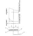
- the cross-sectional area of the branch portion connected to the liquid header portion 7a at the other end (each branch portion) of the flow path formed in the main body portion 6a is determined as the liquid header. It may be formed larger than the cross-sectional area of the branch portion connected to the portion 7b, and the cross-sectional area of the flow channel connected to the liquid header portion 7a may be larger than the cross-sectional area of the flow channel connected to the liquid header portion 7b. Further, for example, as shown in FIG. 4B, an orifice 14 is provided at a branch portion connected to the liquid header portion 7b at the other end (each branch portion) of the flow path formed in the main body portion 6a.
- the two-phase refrigerant is separated into a gas refrigerant and a liquid refrigerant by the first gas / liquid separator 5, and the flow rate of the gas refrigerant is controlled by the flow rate control mechanism 11 and is returned to the suction side of the compressor 1 through the bypass circuit 10.
- the two-phase refrigerant whose dryness is controlled by bypassing the gas refrigerant in the first gas-liquid separator 5 flows into the flow divider 6. That is, the two-phase refrigerant in which the amount of the gas refrigerant is adjusted flows into the flow divider 6.
- the two-phase refrigerant that has flowed into the flow divider 6 is supplied to the liquid header portion 7a and the liquid header portion 7b that are divided into two.
- Embodiment 2 FIG.
- the liquid header portions 7a and 7b are formed in the same shape. Not only this but the shape of the liquid header part 7a and the liquid header part 7b may be varied.
- the inner diameters of the liquid header portion 7a and the liquid header portion 7b may be different as follows. Configurations not described in the second embodiment are the same as those in the first embodiment, and the same configurations as those in the first embodiment are denoted by the same reference numerals as those in the first embodiment.
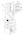
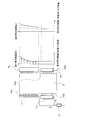
- the solenoid valves 130a, 130b, and 130c provided in the branch pipes 21a, 21b, and 21c are controlled to be closed, and are connected to the indoor units 103a, 103b, and 103c from the second connection pipe 22.
- the solenoid valves 120a, 120b, 120c provided in the pipes are controlled to be open.
- the piping and equipment represented by the solid line indicate the path through which the refrigerant circulates, and the path indicated by the dotted line indicates that the refrigerant does not flow.
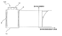
- the two-phase refrigerant that has flowed into the flow divider 6 is supplied to the liquid header portion 7a and the liquid header portion 7b that are divided into two. Then, the two-phase liquid refrigerant supplied to the liquid header portion 7a is converted into each heat transfer tube 15 connected to the liquid header portion 7a (each heat transfer tube 15 arranged in the upper divided region in the outdoor heat exchanger 8). Distributed to. In addition, the two-phase refrigerant supplied to the liquid header portion 7b is distributed to each heat transfer tube 15 (each heat transfer tube 15 disposed in the lower divided region in the outdoor heat exchanger 8) connected to the liquid header portion 7b. Is done.
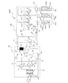
- the gas header 9 connected to a position on the refrigerant outflow side of the outdoor heat exchanger 8 has a plurality of vertical directions. Divided into gas header parts. In FIG. 17, the gas header 9 is divided into two gas header portions 9a and 9b in the vertical direction. Further, the gas header portions 9 a and 9 b are connected to the four-way valve 2 by a refrigerant outlet pipe 46. Specifically, the gas header portion 9a is connected to the four-way valve 2 by a refrigerant outlet pipe 46a. The gas header portion 9b is connected to the four-way valve 2 by a refrigerant outlet pipe 46b.
Landscapes
- Engineering & Computer Science (AREA)
- Physics & Mathematics (AREA)
- Mechanical Engineering (AREA)
- Thermal Sciences (AREA)
- General Engineering & Computer Science (AREA)
- Other Air-Conditioning Systems (AREA)
- Air Conditioning Control Device (AREA)
Abstract
Priority Applications (4)
| Application Number | Priority Date | Filing Date | Title |
|---|---|---|---|
| JP2016520985A JP6058219B2 (ja) | 2014-05-19 | 2015-03-25 | 空気調和装置 |
| EP15796237.4A EP3147591B1 (fr) | 2014-05-19 | 2015-03-25 | Dispositif de climatisation |
| US15/310,875 US10976085B2 (en) | 2014-05-19 | 2015-03-25 | Air-conditioning apparatus |
| CN201580026937.9A CN106461296B (zh) | 2014-05-19 | 2015-03-25 | 空调装置 |
Applications Claiming Priority (2)
| Application Number | Priority Date | Filing Date | Title |
|---|---|---|---|
| JP2014-102954 | 2014-05-19 | ||
| JP2014102954 | 2014-05-19 |
Publications (1)
| Publication Number | Publication Date |
|---|---|
| WO2015178097A1 true WO2015178097A1 (fr) | 2015-11-26 |
Family
ID=54553774
Family Applications (1)
| Application Number | Title | Priority Date | Filing Date |
|---|---|---|---|
| PCT/JP2015/059095 WO2015178097A1 (fr) | 2014-05-19 | 2015-03-25 | Dispositif de climatisation |
Country Status (5)
| Country | Link |
|---|---|
| US (1) | US10976085B2 (fr) |
| EP (1) | EP3147591B1 (fr) |
| JP (1) | JP6058219B2 (fr) |
| CN (1) | CN106461296B (fr) |
| WO (1) | WO2015178097A1 (fr) |
Cited By (11)
| Publication number | Priority date | Publication date | Assignee | Title |
|---|---|---|---|---|
| CN106196507A (zh) * | 2016-08-19 | 2016-12-07 | 芜湖美智空调设备有限公司 | 空调器和空调器的控制方法 |
| JP2017155993A (ja) * | 2016-02-29 | 2017-09-07 | 三菱重工サーマルシステムズ株式会社 | 熱交換器及び空気調和機 |
| JP2017223405A (ja) * | 2016-06-15 | 2017-12-21 | 日立ジョンソンコントロールズ空調株式会社 | 室外機および冷凍サイクル装置 |
| WO2018047416A1 (fr) * | 2016-09-12 | 2018-03-15 | 三菱電機株式会社 | Climatiseur |
| WO2018173256A1 (fr) * | 2017-03-24 | 2018-09-27 | 三菱電機株式会社 | Dispositif de climatisation |
| WO2019021457A1 (fr) * | 2017-07-28 | 2019-01-31 | 三菱電機株式会社 | Distributeur de réfrigérant et dispositif de pompe à chaleur doté de ce distributeur |
| JPWO2018047511A1 (ja) * | 2016-09-12 | 2019-06-24 | 三菱電機株式会社 | 熱交換器および空気調和装置 |
| WO2020162096A1 (fr) * | 2019-02-06 | 2020-08-13 | 株式会社デンソー | Échangeur de chaleur |
| JPWO2019043935A1 (ja) * | 2017-09-04 | 2020-10-01 | 三菱電機株式会社 | 温度調整装置、中継装置、負荷装置、および冷凍サイクル装置 |
| WO2021095439A1 (fr) * | 2019-11-14 | 2021-05-20 | ダイキン工業株式会社 | Échangeur de chaleur |
| US11592193B2 (en) | 2016-09-12 | 2023-02-28 | Mitsubishi Electric Corporation | Air-conditioning apparatus and method of using air-conditioning apparatus |
Families Citing this family (11)
| Publication number | Priority date | Publication date | Assignee | Title |
|---|---|---|---|---|
| CN104748261B (zh) * | 2015-03-31 | 2019-12-03 | 广东美的暖通设备有限公司 | 多联机系统 |
| JP6520353B2 (ja) * | 2015-04-27 | 2019-05-29 | ダイキン工業株式会社 | 熱交換器及び空気調和機 |
| JP6755396B2 (ja) * | 2017-06-13 | 2020-09-16 | 三菱電機株式会社 | 空気調和装置 |
| CN109114838B (zh) * | 2017-06-22 | 2021-07-06 | 青岛海尔新能源电器有限公司 | 一种空气源热泵系统、热水器及控制方法 |
| CN107763774A (zh) * | 2017-11-09 | 2018-03-06 | 青岛海尔空调器有限总公司 | 空调制冷循环系统及空调器 |
| WO2019106755A1 (fr) * | 2017-11-29 | 2019-06-06 | 三菱電機株式会社 | Climatiseur |
| CN110686429A (zh) * | 2018-07-04 | 2020-01-14 | 浙江盾安热工科技有限公司 | 微通道换热器 |
| JP7196187B2 (ja) * | 2018-09-28 | 2022-12-26 | 三菱電機株式会社 | 冷凍サイクル装置の室外機、冷凍サイクル装置、及び空気調和装置 |
| CN110082066B (zh) * | 2019-05-29 | 2024-07-12 | 天津商业大学 | 受下游非均匀换热影响的分流性能测试实验系统 |
| WO2021149222A1 (fr) * | 2020-01-23 | 2021-07-29 | 三菱電機株式会社 | Unité extérieure pour dispositif à cycle de réfrigération |
| CN112628890A (zh) * | 2020-12-21 | 2021-04-09 | 青岛海尔空调电子有限公司 | 热泵系统及空调器 |
Citations (4)
| Publication number | Priority date | Publication date | Assignee | Title |
|---|---|---|---|---|
| JPH07318276A (ja) * | 1994-05-19 | 1995-12-08 | Matsushita Refrig Co Ltd | フィン付き蒸発器 |
| WO2010047420A1 (fr) * | 2008-10-23 | 2010-04-29 | サンデン株式会社 | Système frigorifique à injection de gaz |
| JP2010127601A (ja) * | 2008-12-01 | 2010-06-10 | Fujitsu General Ltd | 空気調和機 |
| JP2012021679A (ja) * | 2010-07-13 | 2012-02-02 | Mitsubishi Electric Corp | 冷媒分配器、それを備えた熱交換器、及び、その熱交換器を搭載した空気調和機 |
Family Cites Families (36)
| Publication number | Priority date | Publication date | Assignee | Title |
|---|---|---|---|---|
| CN1135341C (zh) * | 1994-05-30 | 2004-01-21 | 三菱电机株式会社 | 制冷循环系统 |
| JP3216960B2 (ja) * | 1994-09-19 | 2001-10-09 | 株式会社日立製作所 | 空気調和機の室外機、室内機及びそれらに用いられる冷媒分配器 |
| JP3219014B2 (ja) | 1997-03-27 | 2001-10-15 | ダイキン工業株式会社 | 空調機用熱交換器 |
| KR100332773B1 (ko) * | 1999-09-13 | 2002-04-17 | 구자홍 | 히트 펌프의 증발기 유량 분배장치 |
| JP4180801B2 (ja) | 2001-01-11 | 2008-11-12 | 三菱電機株式会社 | 冷凍空調サイクル装置 |
| JP4554144B2 (ja) * | 2001-06-18 | 2010-09-29 | 昭和電工株式会社 | 蒸発器 |
| JP2004239592A (ja) * | 2002-12-11 | 2004-08-26 | Calsonic Kansei Corp | 車両用熱交換器 |
| ATE354775T1 (de) * | 2003-08-06 | 2007-03-15 | Shell Int Research | Vorrichtung und verfahren zum kühlen von heissgas |
| US7752864B2 (en) * | 2004-08-02 | 2010-07-13 | Daikin Industries, Ltd. | Refrigeration apparatus |
| US7784529B2 (en) * | 2004-11-30 | 2010-08-31 | Showa Denko K.K. | Heat exchanger |
| JP4922669B2 (ja) * | 2006-06-09 | 2012-04-25 | 日立アプライアンス株式会社 | 空気調和機及び空気調和機の熱交換器 |
| JP4766256B2 (ja) * | 2006-07-24 | 2011-09-07 | 株式会社富士通ゼネラル | 空気調和機の制御方法 |
| KR101157799B1 (ko) * | 2007-11-30 | 2012-06-20 | 다이킨 고교 가부시키가이샤 | 냉동 장치 |
| JP5018823B2 (ja) | 2008-07-22 | 2012-09-05 | ブラザー工業株式会社 | シート搬送装置および画像形成装置 |
| KR20100081621A (ko) * | 2009-01-06 | 2010-07-15 | 엘지전자 주식회사 | 공기조화기 및 공기조화기의 제상운전방법 |
| KR20110139283A (ko) * | 2009-03-19 | 2011-12-28 | 다이킨 고교 가부시키가이샤 | 공기 조화 장치 |
| KR101233209B1 (ko) * | 2010-11-18 | 2013-02-15 | 엘지전자 주식회사 | 히트 펌프 |
| JP2012193872A (ja) | 2011-03-15 | 2012-10-11 | Daikin Industries Ltd | 熱交換器および空気調和機 |
| DK177329B1 (en) * | 2011-06-16 | 2013-01-14 | Advansor As | Refrigeration system |
| JP5257491B2 (ja) * | 2011-06-30 | 2013-08-07 | ダイキン工業株式会社 | 冷凍装置の室外機 |
| KR101288745B1 (ko) * | 2011-10-27 | 2013-07-23 | 엘지전자 주식회사 | 공기조화기 |
| MX359679B (es) | 2011-11-21 | 2018-10-05 | Hill Phoenix Inc | Sistema de refrigeracion con dioxido de carbono (co2) con deshielo con gas caliente. |
| EP2792970B1 (fr) * | 2011-12-09 | 2018-10-31 | Daikin Industries, Ltd. | Dispositif de réfrigération de conteneur |
| EP2629030A1 (fr) * | 2011-12-12 | 2013-08-21 | Samsung Electronics Co., Ltd | Climatiseur |
| JP5929450B2 (ja) * | 2012-04-16 | 2016-06-08 | 三菱電機株式会社 | 冷凍サイクル装置 |
| KR101425043B1 (ko) * | 2012-07-26 | 2014-08-01 | 엘지전자 주식회사 | 실외 열교환기 |
| JP5772904B2 (ja) * | 2013-09-02 | 2015-09-02 | ダイキン工業株式会社 | 熱回収型冷凍装置 |
| JP5549773B1 (ja) * | 2013-09-30 | 2014-07-16 | 株式会社富士通ゼネラル | 空気調和装置 |
| JP5747968B2 (ja) * | 2013-10-07 | 2015-07-15 | ダイキン工業株式会社 | 熱回収型冷凍装置 |
| JP6180338B2 (ja) * | 2014-01-29 | 2017-08-16 | ジョンソンコントロールズ ヒタチ エア コンディショニング テクノロジー(ホンコン)リミテッド | 空気調和機 |
| KR101550549B1 (ko) * | 2014-08-01 | 2015-09-04 | 엘지전자 주식회사 | 공기 조화기 |
| US20160123645A1 (en) * | 2014-10-29 | 2016-05-05 | Lg Electronics Inc. | Air conditioner and method of controlling the same |
| JP2017053515A (ja) * | 2015-09-08 | 2017-03-16 | ジョンソンコントロールズ ヒタチ エア コンディショニング テクノロジー(ホンコン)リミテッド | 空気調和機 |
| EP3367021B1 (fr) * | 2015-10-20 | 2022-02-23 | Mitsubishi Electric Corporation | Dispositif à cycle de réfrigération |
| WO2017145219A1 (fr) * | 2016-02-22 | 2017-08-31 | 三菱電機株式会社 | Appareil à cycle frigorifique |
| WO2018051409A1 (fr) * | 2016-09-13 | 2018-03-22 | 三菱電機株式会社 | Appareil à cycle de réfrigération |
-
2015
- 2015-03-25 JP JP2016520985A patent/JP6058219B2/ja active Active
- 2015-03-25 US US15/310,875 patent/US10976085B2/en active Active
- 2015-03-25 CN CN201580026937.9A patent/CN106461296B/zh active Active
- 2015-03-25 EP EP15796237.4A patent/EP3147591B1/fr active Active
- 2015-03-25 WO PCT/JP2015/059095 patent/WO2015178097A1/fr active Application Filing
Patent Citations (4)
| Publication number | Priority date | Publication date | Assignee | Title |
|---|---|---|---|---|
| JPH07318276A (ja) * | 1994-05-19 | 1995-12-08 | Matsushita Refrig Co Ltd | フィン付き蒸発器 |
| WO2010047420A1 (fr) * | 2008-10-23 | 2010-04-29 | サンデン株式会社 | Système frigorifique à injection de gaz |
| JP2010127601A (ja) * | 2008-12-01 | 2010-06-10 | Fujitsu General Ltd | 空気調和機 |
| JP2012021679A (ja) * | 2010-07-13 | 2012-02-02 | Mitsubishi Electric Corp | 冷媒分配器、それを備えた熱交換器、及び、その熱交換器を搭載した空気調和機 |
Non-Patent Citations (1)
| Title |
|---|
| See also references of EP3147591A4 * |
Cited By (21)
| Publication number | Priority date | Publication date | Assignee | Title |
|---|---|---|---|---|
| JP2017155993A (ja) * | 2016-02-29 | 2017-09-07 | 三菱重工サーマルシステムズ株式会社 | 熱交換器及び空気調和機 |
| JP2017223405A (ja) * | 2016-06-15 | 2017-12-21 | 日立ジョンソンコントロールズ空調株式会社 | 室外機および冷凍サイクル装置 |
| CN106196507A (zh) * | 2016-08-19 | 2016-12-07 | 芜湖美智空调设备有限公司 | 空调器和空调器的控制方法 |
| GB2569898B (en) * | 2016-09-12 | 2021-02-03 | Mitsubishi Electric Corp | Air-conditioning apparatus |
| WO2018047416A1 (fr) * | 2016-09-12 | 2018-03-15 | 三菱電機株式会社 | Climatiseur |
| WO2018047330A1 (fr) * | 2016-09-12 | 2018-03-15 | 三菱電機株式会社 | Climatiseur |
| US11592193B2 (en) | 2016-09-12 | 2023-02-28 | Mitsubishi Electric Corporation | Air-conditioning apparatus and method of using air-conditioning apparatus |
| US11156412B2 (en) | 2016-09-12 | 2021-10-26 | Mitsubishi Electric Corporation | Heat exchanger and air-conditioning apparatus |
| JPWO2018047416A1 (ja) * | 2016-09-12 | 2019-04-25 | 三菱電機株式会社 | 空気調和装置 |
| JPWO2018047511A1 (ja) * | 2016-09-12 | 2019-06-24 | 三菱電機株式会社 | 熱交換器および空気調和装置 |
| GB2569898A (en) * | 2016-09-12 | 2019-07-03 | Mitsubishi Electric Corp | Air conditioner |
| JPWO2018173256A1 (ja) * | 2017-03-24 | 2019-11-07 | 三菱電機株式会社 | 空気調和装置 |
| US11543185B2 (en) | 2017-03-24 | 2023-01-03 | Mitsubishi Electric Corporation | Air-conditioning apparatus |
| WO2018173256A1 (fr) * | 2017-03-24 | 2018-09-27 | 三菱電機株式会社 | Dispositif de climatisation |
| WO2019021457A1 (fr) * | 2017-07-28 | 2019-01-31 | 三菱電機株式会社 | Distributeur de réfrigérant et dispositif de pompe à chaleur doté de ce distributeur |
| JPWO2019043935A1 (ja) * | 2017-09-04 | 2020-10-01 | 三菱電機株式会社 | 温度調整装置、中継装置、負荷装置、および冷凍サイクル装置 |
| JP2020125896A (ja) * | 2019-02-06 | 2020-08-20 | 株式会社デンソー | 熱交換器 |
| WO2020162096A1 (fr) * | 2019-02-06 | 2020-08-13 | 株式会社デンソー | Échangeur de chaleur |
| JP7255215B2 (ja) | 2019-02-06 | 2023-04-11 | 株式会社デンソー | 熱交換器 |
| WO2021095439A1 (fr) * | 2019-11-14 | 2021-05-20 | ダイキン工業株式会社 | Échangeur de chaleur |
| JP2021081076A (ja) * | 2019-11-14 | 2021-05-27 | ダイキン工業株式会社 | 熱交換器 |
Also Published As
| Publication number | Publication date |
|---|---|
| US10976085B2 (en) | 2021-04-13 |
| CN106461296B (zh) | 2019-03-05 |
| EP3147591A1 (fr) | 2017-03-29 |
| JPWO2015178097A1 (ja) | 2017-04-20 |
| JP6058219B2 (ja) | 2017-01-11 |
| EP3147591A4 (fr) | 2018-01-31 |
| US20170082332A1 (en) | 2017-03-23 |
| EP3147591B1 (fr) | 2022-04-13 |
| CN106461296A (zh) | 2017-02-22 |
Similar Documents
| Publication | Publication Date | Title |
|---|---|---|
| JP6058219B2 (ja) | 空気調和装置 | |
| JP6685409B2 (ja) | 空気調和装置 | |
| CN109328287B (zh) | 制冷循环装置 | |
| WO2014083867A1 (fr) | Dispositif de conditionnement d'air | |
| WO2015059792A1 (fr) | Climatiseur | |
| JP6045695B2 (ja) | 空気調和装置 | |
| WO2015063853A1 (fr) | Cycle de réfrigération et climatiseur | |
| JP5774216B2 (ja) | 多室型空気調和装置 | |
| JP6715929B2 (ja) | 冷凍サイクル装置およびそれを備えた空気調和装置 | |
| WO2018029817A1 (fr) | Dispositif à cycle de réfrigération | |
| JP2017101855A (ja) | 空気調和装置 | |
| WO2016208042A1 (fr) | Dispositif de climatisation | |
| JP2020020576A (ja) | 冷凍サイクル装置およびそれを備えた空気調和装置 | |
| JP6576603B1 (ja) | 空気調和装置 | |
| JP2015010816A (ja) | 冷媒回路および空気調和装置 | |
| JPWO2020174619A1 (ja) | 空気調和装置 | |
| JP2017101854A (ja) | 空気調和装置 | |
| JP5968540B2 (ja) | 冷媒回路および空気調和装置 | |
| JP7065681B2 (ja) | 空気調和装置 | |
| JP2017142027A (ja) | 空気調和装置 | |
| WO2023238181A1 (fr) | Dispositif de climatisation | |
| JP7433470B2 (ja) | 冷凍サイクル装置 | |
| JP7146077B2 (ja) | 熱交換器及び空気調和装置 | |
| JP2018128167A (ja) | 空気調和装置 |
Legal Events
| Date | Code | Title | Description |
|---|---|---|---|
| 121 | Ep: the epo has been informed by wipo that ep was designated in this application |
Ref document number: 15796237 Country of ref document: EP Kind code of ref document: A1 |
|
| ENP | Entry into the national phase |
Ref document number: 2016520985 Country of ref document: JP Kind code of ref document: A |
|
| WWE | Wipo information: entry into national phase |
Ref document number: 15310875 Country of ref document: US |
|
| REEP | Request for entry into the european phase |
Ref document number: 2015796237 Country of ref document: EP |
|
| WWE | Wipo information: entry into national phase |
Ref document number: 2015796237 Country of ref document: EP |
|
| NENP | Non-entry into the national phase |
Ref country code: DE |