EP3147591B1 - Dispositif de climatisation - Google Patents
Dispositif de climatisation Download PDFInfo
- Publication number
- EP3147591B1 EP3147591B1 EP15796237.4A EP15796237A EP3147591B1 EP 3147591 B1 EP3147591 B1 EP 3147591B1 EP 15796237 A EP15796237 A EP 15796237A EP 3147591 B1 EP3147591 B1 EP 3147591B1
- Authority
- EP
- European Patent Office
- Prior art keywords
- refrigerant
- gas
- liquid
- heat exchanger
- air
- Prior art date
- Legal status (The legal status is an assumption and is not a legal conclusion. Google has not performed a legal analysis and makes no representation as to the accuracy of the status listed.)
- Active
Links
- 238000004378 air conditioning Methods 0.000 title claims description 103
- 239000003507 refrigerant Substances 0.000 claims description 396
- 239000007788 liquid Substances 0.000 claims description 378
- 238000010438 heat treatment Methods 0.000 claims description 69
- 238000001816 cooling Methods 0.000 claims description 48
- 230000007246 mechanism Effects 0.000 claims description 17
- 239000000203 mixture Substances 0.000 claims description 8
- 230000004907 flux Effects 0.000 claims description 7
- 238000005057 refrigeration Methods 0.000 claims description 7
- 230000003247 decreasing effect Effects 0.000 claims description 6
- 230000007423 decrease Effects 0.000 claims description 4
- 239000012071 phase Substances 0.000 description 55
- 238000010586 diagram Methods 0.000 description 16
- 230000000694 effects Effects 0.000 description 5
- 238000000034 method Methods 0.000 description 3
- 238000009835 boiling Methods 0.000 description 2
- 238000007599 discharging Methods 0.000 description 2
- 230000008569 process Effects 0.000 description 2
- 230000009467 reduction Effects 0.000 description 2
- 238000000926 separation method Methods 0.000 description 2
- 230000002528 anti-freeze Effects 0.000 description 1
- 230000005494 condensation Effects 0.000 description 1
- 238000009833 condensation Methods 0.000 description 1
- 239000000470 constituent Substances 0.000 description 1
- 230000001419 dependent effect Effects 0.000 description 1
- 230000006866 deterioration Effects 0.000 description 1
- 238000011161 development Methods 0.000 description 1
- 230000018109 developmental process Effects 0.000 description 1
- 238000005265 energy consumption Methods 0.000 description 1
- 238000001704 evaporation Methods 0.000 description 1
- 230000008020 evaporation Effects 0.000 description 1
- 230000006872 improvement Effects 0.000 description 1
- 239000007791 liquid phase Substances 0.000 description 1
- 230000000116 mitigating effect Effects 0.000 description 1
- XLYOFNOQVPJJNP-UHFFFAOYSA-N water Substances O XLYOFNOQVPJJNP-UHFFFAOYSA-N 0.000 description 1
Images


Classifications
-
- F—MECHANICAL ENGINEERING; LIGHTING; HEATING; WEAPONS; BLASTING
- F25—REFRIGERATION OR COOLING; COMBINED HEATING AND REFRIGERATION SYSTEMS; HEAT PUMP SYSTEMS; MANUFACTURE OR STORAGE OF ICE; LIQUEFACTION SOLIDIFICATION OF GASES
- F25B—REFRIGERATION MACHINES, PLANTS OR SYSTEMS; COMBINED HEATING AND REFRIGERATION SYSTEMS; HEAT PUMP SYSTEMS
- F25B41/00—Fluid-circulation arrangements
- F25B41/20—Disposition of valves, e.g. of on-off valves or flow control valves
-
- F—MECHANICAL ENGINEERING; LIGHTING; HEATING; WEAPONS; BLASTING
- F25—REFRIGERATION OR COOLING; COMBINED HEATING AND REFRIGERATION SYSTEMS; HEAT PUMP SYSTEMS; MANUFACTURE OR STORAGE OF ICE; LIQUEFACTION SOLIDIFICATION OF GASES
- F25B—REFRIGERATION MACHINES, PLANTS OR SYSTEMS; COMBINED HEATING AND REFRIGERATION SYSTEMS; HEAT PUMP SYSTEMS
- F25B1/00—Compression machines, plants or systems with non-reversible cycle
-
- F—MECHANICAL ENGINEERING; LIGHTING; HEATING; WEAPONS; BLASTING
- F25—REFRIGERATION OR COOLING; COMBINED HEATING AND REFRIGERATION SYSTEMS; HEAT PUMP SYSTEMS; MANUFACTURE OR STORAGE OF ICE; LIQUEFACTION SOLIDIFICATION OF GASES
- F25B—REFRIGERATION MACHINES, PLANTS OR SYSTEMS; COMBINED HEATING AND REFRIGERATION SYSTEMS; HEAT PUMP SYSTEMS
- F25B13/00—Compression machines, plants or systems, with reversible cycle
-
- F—MECHANICAL ENGINEERING; LIGHTING; HEATING; WEAPONS; BLASTING
- F25—REFRIGERATION OR COOLING; COMBINED HEATING AND REFRIGERATION SYSTEMS; HEAT PUMP SYSTEMS; MANUFACTURE OR STORAGE OF ICE; LIQUEFACTION SOLIDIFICATION OF GASES
- F25B—REFRIGERATION MACHINES, PLANTS OR SYSTEMS; COMBINED HEATING AND REFRIGERATION SYSTEMS; HEAT PUMP SYSTEMS
- F25B39/00—Evaporators; Condensers
- F25B39/02—Evaporators
-
- F—MECHANICAL ENGINEERING; LIGHTING; HEATING; WEAPONS; BLASTING
- F25—REFRIGERATION OR COOLING; COMBINED HEATING AND REFRIGERATION SYSTEMS; HEAT PUMP SYSTEMS; MANUFACTURE OR STORAGE OF ICE; LIQUEFACTION SOLIDIFICATION OF GASES
- F25B—REFRIGERATION MACHINES, PLANTS OR SYSTEMS; COMBINED HEATING AND REFRIGERATION SYSTEMS; HEAT PUMP SYSTEMS
- F25B49/00—Arrangement or mounting of control or safety devices
- F25B49/02—Arrangement or mounting of control or safety devices for compression type machines, plants or systems
-
- F—MECHANICAL ENGINEERING; LIGHTING; HEATING; WEAPONS; BLASTING
- F28—HEAT EXCHANGE IN GENERAL
- F28D—HEAT-EXCHANGE APPARATUS, NOT PROVIDED FOR IN ANOTHER SUBCLASS, IN WHICH THE HEAT-EXCHANGE MEDIA DO NOT COME INTO DIRECT CONTACT
- F28D1/00—Heat-exchange apparatus having stationary conduit assemblies for one heat-exchange medium only, the media being in contact with different sides of the conduit wall, in which the other heat-exchange medium is a large body of fluid, e.g. domestic or motor car radiators
- F28D1/02—Heat-exchange apparatus having stationary conduit assemblies for one heat-exchange medium only, the media being in contact with different sides of the conduit wall, in which the other heat-exchange medium is a large body of fluid, e.g. domestic or motor car radiators with heat-exchange conduits immersed in the body of fluid
- F28D1/04—Heat-exchange apparatus having stationary conduit assemblies for one heat-exchange medium only, the media being in contact with different sides of the conduit wall, in which the other heat-exchange medium is a large body of fluid, e.g. domestic or motor car radiators with heat-exchange conduits immersed in the body of fluid with tubular conduits
- F28D1/047—Heat-exchange apparatus having stationary conduit assemblies for one heat-exchange medium only, the media being in contact with different sides of the conduit wall, in which the other heat-exchange medium is a large body of fluid, e.g. domestic or motor car radiators with heat-exchange conduits immersed in the body of fluid with tubular conduits the conduits being bent, e.g. in a serpentine or zig-zag
-
- F—MECHANICAL ENGINEERING; LIGHTING; HEATING; WEAPONS; BLASTING
- F25—REFRIGERATION OR COOLING; COMBINED HEATING AND REFRIGERATION SYSTEMS; HEAT PUMP SYSTEMS; MANUFACTURE OR STORAGE OF ICE; LIQUEFACTION SOLIDIFICATION OF GASES
- F25B—REFRIGERATION MACHINES, PLANTS OR SYSTEMS; COMBINED HEATING AND REFRIGERATION SYSTEMS; HEAT PUMP SYSTEMS
- F25B2313/00—Compression machines, plants or systems with reversible cycle not otherwise provided for
- F25B2313/023—Compression machines, plants or systems with reversible cycle not otherwise provided for using multiple indoor units
- F25B2313/0233—Compression machines, plants or systems with reversible cycle not otherwise provided for using multiple indoor units in parallel arrangements
-
- F—MECHANICAL ENGINEERING; LIGHTING; HEATING; WEAPONS; BLASTING
- F25—REFRIGERATION OR COOLING; COMBINED HEATING AND REFRIGERATION SYSTEMS; HEAT PUMP SYSTEMS; MANUFACTURE OR STORAGE OF ICE; LIQUEFACTION SOLIDIFICATION OF GASES
- F25B—REFRIGERATION MACHINES, PLANTS OR SYSTEMS; COMBINED HEATING AND REFRIGERATION SYSTEMS; HEAT PUMP SYSTEMS
- F25B2313/00—Compression machines, plants or systems with reversible cycle not otherwise provided for
- F25B2313/029—Control issues
- F25B2313/0294—Control issues related to the outdoor fan, e.g. controlling speed
-
- F—MECHANICAL ENGINEERING; LIGHTING; HEATING; WEAPONS; BLASTING
- F25—REFRIGERATION OR COOLING; COMBINED HEATING AND REFRIGERATION SYSTEMS; HEAT PUMP SYSTEMS; MANUFACTURE OR STORAGE OF ICE; LIQUEFACTION SOLIDIFICATION OF GASES
- F25B—REFRIGERATION MACHINES, PLANTS OR SYSTEMS; COMBINED HEATING AND REFRIGERATION SYSTEMS; HEAT PUMP SYSTEMS
- F25B2400/00—General features or devices for refrigeration machines, plants or systems, combined heating and refrigeration systems or heat-pump systems, i.e. not limited to a particular subgroup of F25B
- F25B2400/23—Separators
-
- F—MECHANICAL ENGINEERING; LIGHTING; HEATING; WEAPONS; BLASTING
- F25—REFRIGERATION OR COOLING; COMBINED HEATING AND REFRIGERATION SYSTEMS; HEAT PUMP SYSTEMS; MANUFACTURE OR STORAGE OF ICE; LIQUEFACTION SOLIDIFICATION OF GASES
- F25B—REFRIGERATION MACHINES, PLANTS OR SYSTEMS; COMBINED HEATING AND REFRIGERATION SYSTEMS; HEAT PUMP SYSTEMS
- F25B2500/00—Problems to be solved
- F25B2500/09—Improving heat transfers
-
- F—MECHANICAL ENGINEERING; LIGHTING; HEATING; WEAPONS; BLASTING
- F25—REFRIGERATION OR COOLING; COMBINED HEATING AND REFRIGERATION SYSTEMS; HEAT PUMP SYSTEMS; MANUFACTURE OR STORAGE OF ICE; LIQUEFACTION SOLIDIFICATION OF GASES
- F25B—REFRIGERATION MACHINES, PLANTS OR SYSTEMS; COMBINED HEATING AND REFRIGERATION SYSTEMS; HEAT PUMP SYSTEMS
- F25B2600/00—Control issues
- F25B2600/25—Control of valves
- F25B2600/2501—Bypass valves
-
- F—MECHANICAL ENGINEERING; LIGHTING; HEATING; WEAPONS; BLASTING
- F25—REFRIGERATION OR COOLING; COMBINED HEATING AND REFRIGERATION SYSTEMS; HEAT PUMP SYSTEMS; MANUFACTURE OR STORAGE OF ICE; LIQUEFACTION SOLIDIFICATION OF GASES
- F25B—REFRIGERATION MACHINES, PLANTS OR SYSTEMS; COMBINED HEATING AND REFRIGERATION SYSTEMS; HEAT PUMP SYSTEMS
- F25B2600/00—Control issues
- F25B2600/25—Control of valves
- F25B2600/2511—Evaporator distribution valves
-
- F—MECHANICAL ENGINEERING; LIGHTING; HEATING; WEAPONS; BLASTING
- F25—REFRIGERATION OR COOLING; COMBINED HEATING AND REFRIGERATION SYSTEMS; HEAT PUMP SYSTEMS; MANUFACTURE OR STORAGE OF ICE; LIQUEFACTION SOLIDIFICATION OF GASES
- F25B—REFRIGERATION MACHINES, PLANTS OR SYSTEMS; COMBINED HEATING AND REFRIGERATION SYSTEMS; HEAT PUMP SYSTEMS
- F25B39/00—Evaporators; Condensers
- F25B39/02—Evaporators
- F25B39/028—Evaporators having distributing means
Definitions
- the present invention relates to an air-conditioning apparatus.
- Distribution of the wind speed (air quantity) of the air passing through a heat exchanger is generally not uniform but is distributed.
- the wind speed in the outdoor heat exchanger is distributed in such a manner that the wind speed of the upper side increases and the wind speed in the lower side decreases.
- the performance of the heat exchanger may not be drawn out.
- the heat exchanger is an evaporator
- the refrigerant cannot be evaporated completely at a portion of a heat transfer tube where air quantity passing through is small, so that the performance of the heat exchanger cannot be drawn out.
- Patent Literature 2 relates to a refrigeration system using CO2 as a refrigerant includes a receiver having a liquid outlet connected to expansion valves, which are connected to evaporators, which are connected to the suction side of the compressor.
- the receiver includes a second gas outlet connected to a second pressure reduction device, to reduce the energy consumption in CO2 cooling systems and to protect the compressors against liquid CO2 by heating the suction gas.
- the second pressure reduction device is connected by tubing to a first heat exchanging device, which is integrated in the receiver, so that gas that is evaporated in the top of a receiver can be used for cooling the liquid part of the same receiver.
- Patent Literature 3 relates to a C02 refrigeration system has an LT system with LT compressors and LT evaporators, and an MT system with MT compressors and MT evaporators, operating in a refrigeration mode and a defrost mode using C02 hot gas discharge from the MT and/or the LT compressors to defrost the LT evaporators.
- a C02 refrigerant circuit directs C02 refrigerant through the system and has an LT compressor discharge line with a hot gas discharge valve, a C02 hot gas defrost supply header directing C02 hot gas discharge from the LT and/or the MT compressors to the LT evaporators, a flash tank supplying C02 refrigerant to the MT and LT evaporators during the refrigeration mode, and receiving the C02 hot gas discharge from the LT evaporators during the defrost mode, and a control system directing the C02 hot gas discharge through the LT evaporators and to the flash tank during the defrost mode.
- Patent Literature 4 relates to an air conditioner which connects an outdoor unit 13 comprising compressors 1, 2, a four-way valve 3, a heat source side heat exchanger 4, an outdoor motor-operated valve 6 and an outdoor blower 8, to an indoor unit 12 comprising a motor-operated expansion valve 9, a utilization side heat exchanger 10 and an indoor blower 11, by liquid connection piping 14 and gas connection piping 15.
- the heat source side heat exchanger is a fin tube type heat exchanger structured to have three or more rows of heat exchangers.
- the heat source side heat exchanger is to have condensation opposed flow in air-conditioning and evaporation parallel flow in heating to the air flow of the blower, and refrigerant distribution adjustment can be made considering the blower air flow for every heat exchange path.
- An object of the present invention is to achieve an air-conditioning apparatus that enables allocation of two-phase refrigerant according to the distribution of the wind speed in a divided region of an outdoor heat exchanger, and enables improvement of performance of the outdoor heat exchanger.
- two-phase refrigerant in which the quality is adjusted by the first gas-liquid separator is supplied to the shunt.
- the speed of gas refrigerant flowing in each liquid header portion can be adjusted.
- the shunt supplies, to each liquid header portion, the two-phase refrigerant of the amount corresponding to the divided region of the outdoor heat exchanger to which each liquid header portion is connected.
- the amount of liquid refrigerant lifted upward by the gas refrigerant in the liquid header portion can be adjusted according to the wind speed distribution, and the refrigerant can be supplied to the divided region along the wind speed distribution, whereby it is possible to improve the performance of the outdoor heat exchanger sufficiently.
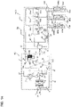
- FIG. 1 is a refrigerant circuit diagram of an air-conditioning apparatus according to Embodiment 1 of the present invention.
- An air-conditioning apparatus 300 of Embodiment 1 includes a compressor 1, a four-way valve 2, an indoor heat exchanger 3, an expansion valve 4, and an outdoor heat exchanger 8. This means that at the time of heating operation, the refrigeration cycle of the air-conditioning apparatus 300 is configured such that the compressor 1, the four-way valve 2, the indoor heat exchanger 3, the expansion valve 4, and the outdoor heat exchanger 8 are connected in this order.
- the refrigeration cycle of the air-conditioning apparatus 300 is configured such that the compressor 1, the four-way valve 2, the outdoor heat exchanger 8, the expansion valve 4, and the indoor heat exchanger 3 are connected in this order.
- the indoor heat exchanger 3 functions as a condenser at the time of heating operation, and functions as an evaporator at the time of cooling operation.
- the outdoor heat exchanger 8 functions as an evaporator at the time of heating operation, and functions as a condenser at the time of cooling operation.
- the four-way valve 2 is not particularly required.
- the outdoor heat exchanger 8 is configured of a plurality of fins 16 and a plurality of heat transfer tubes 15, as described below.
- One end portion (end portion of a refrigerant inflow side at the time of heating operation) of each heat transfer tube 15 is connected with a liquid header 7, and the other end portion (end portion of a refrigerant outflow side at the time of heating operation) of each heat transfer tube 15 is connected with a gas header 9.
- the liquid header 7 is divided into two liquid header portions 7a and 7b in an up and down direction.
- the air-conditioning apparatus 300 of Embodiment 1 includes a first gas-liquid separator 5 for separating two-phase refrigerant, having flowed out of the expansion valve 4, into gas refrigerant and liquid refrigerant at the time of heating operation, and a bypass 10 that connects the first gas-liquid separator 5 and the suction side of the compressor 1 and adjusts the quantity of the gas refrigerant, separated by the first gas-liquid separator 5, to be returned to the suction side of the compressor 1.
- the bypass 10 connects the first gas-liquid separator 5 and the suction side of the compressor 1, and is configured of a first bypass pipe 10a for returning gas refrigerant, separated by the first gas-liquid separator 5, to the suction side of the compressor 1, and a flow rate control mechanism 11 (flow rate control valve, for example) that adjust the flow rate of the gas refrigerant flowing in the first bypass pipe 10a.
- a flow rate control mechanism 11 flow rate control valve, for example
- the air-conditioning apparatus 300 of Embodiment 1 further includes a shunt 6 that connects the first gas-liquid separator 5 and lower portions, for example, of the respective liquid header portions 7a and 7b, and supplies the two-phase refrigerant, in which the quality is adjusted by the first gas-liquid separator 5, to the liquid header portions 7a and 7b, respectively.
- a shunt 6 that connects the first gas-liquid separator 5 and lower portions, for example, of the respective liquid header portions 7a and 7b, and supplies the two-phase refrigerant, in which the quality is adjusted by the first gas-liquid separator 5, to the liquid header portions 7a and 7b, respectively.
- the above-described constituent elements, constituting the air-conditioning apparatus 300, are stored in an outdoor unit 100 and an indoor unit 200.
- the compressor 1, the four-way valve 2, the expansion valve 4, the first gas-liquid separator 5, the shunt 6, the liquid header 7, the outdoor heat exchanger 8, the gas header 9, and the bypass 10 are stored.
- the indoor heat exchanger 3 is stored.
- the outdoor unit 100 is also provided with a fan 12 that supplies air (outdoor air), to which heat exchange is applied, to the outdoor heat exchanger 8. The configuration of storing the fan 12 in the outdoor unit 100 will be described below.
- the air-conditioning apparatus 300 of Embodiment 1 also includes a controller 20 configured of a microcomputer, for example.
- the controller 20 controls the rotation speed of the compressor 1, the flow channel of the four-way valve 2, the opening degree of the expansion valve 4, the opening degree of the flow rate control mechanism 11, the rotation speed (air quantity) of the fan 12, and the like.
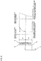
- FIG. 2 is a vertical sectional view of an outdoor unit of the air-conditioning apparatus according to Embodiment 1 of the present invention.
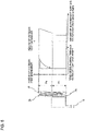
- FIG. 3 illustrates an outdoor heat exchanger of the air-conditioning apparatus according to Embodiment 1 of the present invention. It should be noted that in FIG. 2 , wind speed distribution passing through the outdoor heat exchanger 8 is also shown.
- (a) is a plan view
- (b) is a side view.
- the outdoor unit 100 according to Embodiment 1 includes an approximately rectangular parallelepiped casing 13. At least one side face of the casing 13 has an air inlet, and the outdoor heat exchanger 8 is provided to face the air inlet. It should be noted that in Embodiment 1, air inlets are formed in three side faces of the casing 13. As such, as shown in FIG. 3 , the outdoor heat exchanger 8 according to Embodiment 1 is formed in a U shape in a plan view. It should be noted that air inlets may be formed in four side faces, rather than three side faces, of the casing 13, and the outdoor heat exchanger 8 may be formed in a square shape in a plan view, for example.
- the outdoor heat exchanger 8 is configured of a plurality of fins 16 and a plurality of heat transfer tubes 15.
- the fins 16 are in a substantially rectangular shape extended in the up and down direction, and the respective fins 16 are arranged in parallel in a horizontal direction at predetermined intervals.
- the heat transfer tubes 15 are formed in a U shape in a plan view, and the respective heat transfer tubes 15 are arranged in parallel at predetermined intervals in the up and down direction so as to penetrate the fins 16. It should be noted that the heat transfer tube 15 of Embodiment 1 is formed in a U shape, and at an end portion of one side of the U shape, it is folded to be in a U shape again.
- both an end potion of the liquid header 7 (liquid header portions 7a and 7b) side and an end portion of the gas header 9 side of the heat transfer tube 15 are arranged at an end portion of one side of the U shape.
- the arrangement method may not be limited to an end portion of one side.
- the end portions of the liquid header 7 (liquid header portions 7a and 7b) side and the gas header 9 side may be arranged at end portions on both sides of the U shape.
- the outdoor unit 100 of Embodiment 1 has an air outlet formed in an upper portion of the casing 13, and the fan 12 equivalent to an outdoor fan of the present invention is provided below the air outlet.
- the outdoor unit 100 of Embodiment 1 is configured such that the air sucked into the casing 13 by the fan 12 exchanges heat with the outdoor heat exchanger 8 and then discharged from the upper portion of the casing 13. As such, as shown in FIG. 2 , as the wind speed is faster at a portion near the fan 12, the wind speed (air quantity) passing through the outdoor heat exchanger 8 increases as it comes close to the fan 12.
- the liquid header 7 has a pipe structure that is divided into two liquid header portions 7a and 7b in an up and down direction so as to extend upward and downward.
- the heat transfer tubes 15 arranged in an upper portion of the outdoor heat exchanger 8 are connected with the liquid header portion 7a, and the heat transfer tubes 15 arranged in the lower portion of the outdoor heat exchanger 8 are connected with the liquid header portion 7b.
- the outdoor heat exchanger 8 is divided into a plurality of divided regions in the up and down direction, and different liquid header portions are connected with the respective different regions.
- the shunt 6 supplies two-phase refrigerant of the amount corresponding to the air quantity of the divided regions connected with the liquid header portion 7a and 7b, with respect to the respective liquid header portion 7a and 7b. Specifically, the shunt 6 supplies the two-phase refrigerant to the respective liquid header portions 7a and 7b such that an average refrigerant flow rate of the heat transfer tubes 15 connected with the liquid header portion 7a (flow rate of two-phase refrigerant supplied to the liquid header portion 7a / the number of heat transfer tubes 15 connected with the liquid header portion 7a) becomes larger than an average refrigerant flow rate of the heat transfer tubes 15 connected with the liquid header portion 7b (flow rate of two-phase refrigerant supplied to the liquid header portion 7b / the number of heat transfer tubes 15 connected with the liquid header portion 7b).
- the shunt 6 of Embodiment 1 is formed such that the inner diameter of the flow channels connected with the liquid header portions 7a and 7b differs according to each liquid header portion. Thereby, the amount of two-phase refrigerant supplied to each of the liquid header portions 7a and 7b can be changed.
- FIG. 4 is a sectional view illustrating an example of the shunt in the air-conditioning apparatus according to Embodiment 1 of the present invention.
- the shunt 6 includes a main body 6a and connection pipes 6b of the same number as the number of liquid header portions.
- the main body 6a has a flow channel in which one end is connected with the first gas-liquid separator 5, and the other end is branched to be in the same number as the number of the liquid header portions.
- the connection pipe 6b is configured such that one end thereof is connected with another end (each branched portion) of the flow channel formed in the main body 6a, and the other end is connected with each of the liquid header portions 7a and 7b.
- the sectional area of the branched portion connected with the liquid header portion 7a is formed to be larger than the sectional area of the branched portion connected with the liquid header portion 7b, and that the sectional area of the flow channel connected with the liquid header portion 7a is formed to be larger than the sectional area of the flow channel connected with the liquid header portion 7b.
- an orifice 14 is provided to the branched portion connected with the liquid header portion 7b, and that the sectional area of the flow channel connected with the liquid header portion 7a is formed to be larger than the sectional area of the flow channel connected with the liquid header portion 7b.
- the sectional area of the connection pipe 6b connected with the liquid header portion 7a is formed to be larger than the sectional area of the connection pipe 6b connected with the liquid header portion 7b, and that the sectional area of the flow channel connected with the liquid header portion 7a is formed to be larger than the sectional area of the flow channel connected with the liquid header portion 7b.
- a larger amount of refrigerant can be supplied to the liquid header portion 7a side connected with a divided region of larger air quantity.
- the length of the connection pipe unit 6b connected with the liquid header portion 7a may be formed to be longer than the length of the connection pipe unit 6b connected with the liquid header portion 7b. Even such a configuration, a larger amount of refrigerant can be supplied to the liquid header portion 7a side connected with a divided region of a large air quantity.
- the flow dividing ratio of the refrigerant supplied to the liquid header portion 7a and the liquid header portion 7b may be fixed according to the air quantity distribution in an operating state where the air quantity distribution is biased most. Further, as shown in FIG. 8 or FIG. 9 described below, in the case where the liquid header 7 is divided into three or more, it is only necessary to increase the number of the branched portions of the flow channel formed in the main body 6a and the number of the connection pipes 6b.
- gas refrigerant compressed to be high temperature and high pressure by the compressor 1 flows into the indoor heat exchanger 3 along with the solid line of the four-way valve 2, and exchanges heat with the indoor air and discharges heat to the indoor by an air sending means such as a fan not shown, whereby the gas refrigerant is condensed to be high-temperature and high-pressure liquid refrigerant.
- the high-temperature and high-pressure liquid refrigerant is decompressed by the expansion valve 4 to be two-phase refrigerant, and flows into the first gas-liquid separator 5.
- the two-phase refrigerant is separated into gas refrigerant and liquid refrigerant.
- the flow rate thereof is controlled by the flow rate control mechanism 11, and the gas refrigerant is returned to the suction side of the compressor 1 through the bypass 10.
- the two-phase refrigerant in which the quality is controlled by bypassing the gas refrigerant in the first gas-liquid separator 5, flows into the shunt 6.
- the two-phase refrigerant in which the amount of gas refrigerant is adjusted, flows into the shunt 6.
- the two-phase refrigerant having flowed in the shunt 6 is supplied to the liquid header portion 7a and the liquid header portion 7b that are divided into two.
- the two-phase refrigerant supplied to the liquid header portion 7a is allocated to the respective heat transfer tubes 15 connected with the liquid header portion 7a (respective heat transfer tubes 15 arranged in the upper divided region in the outdoor heat exchanger 8). Further, the two-phase refrigerant supplied to the liquid header portion 7b is allocated to the respective heat transfer tubes 15 connected with the liquid header portion 7b (respective heat transfer tubes 15 arranged in the lower divided region in the outdoor heat exchanger 8).
- refrigerant is allocated to the respective heat transfer tubes 15 as shown in FIG. 5 .
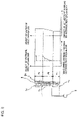
- FIG. 5 illustrates distribution of refrigerant allocation in the outdoor heat exchanger of the air-conditioning apparatus according to Embodiment 1 of the present invention.
- the shunt 6 supplies, to the respective liquid header portions 7a and 7b, two-phase refrigerant of the amount corresponding to the air quantities of the divided regions connected with the liquid header portions 7a and 7b.
- a larger amount of two-phase refrigerant is supplied to the liquid header portion 7a connected with the upper divided region of the outdoor heat exchanger 8 of a larger air quantity, than that supplied to the liquid header portion 7b connected with the lower divided region of the outdoor heat exchanger 8 of a smaller air quantity.
- the outdoor heat exchanger 8 can be used efficiently.
- two-phase refrigerant in which the amount of gas refrigerant is adjusted, flows into the liquid header portions 7a and 7b.
- the refrigerant in which the gas refrigerant speed is adjusted, flows into the liquid header portions 7a and 7b.
- the liquid refrigerant in the liquid header portions 7a and 7b is lifted upward accompanied by the gas refrigerant. Accordingly, with respect to the heat transfer tube 15 of a divided region, refrigerant can be supplied along with the wind speed distribution (air quantity distribution) of the divided region. As such, the performance of the outdoor heat exchanger 8 can be further improved.
- the opening degree of the flow rate control mechanism 11 may be decreased to increase the amount of gas refrigerant flowing into the liquid header portions 7a and 7b to increase the gas refrigerant speed in the liquid header portions 7a and 7b.
- the amount of liquid refrigerant lifted upward is increased, which enables the refrigerant to be allocated according to the wind speed distribution in the divided region.
- the opening degree of the flow rate control mechanism 11 may be increased to decrease the amount of gas refrigerant flowing into the liquid header portions 7a and 7b to decrease the gas refrigerant speed in the liquid header portions 7a and 7b. Thereby, the amount of liquid refrigerant lifted upward is decreased, which enables the refrigerant to be allocated according to the wind speed distribution in the divided region.
- the two-phase refrigerant flowing into the respective heat transfer tubes 15 of the outdoor heat exchanger 8 as described above, exchanges heat with the outdoor air and absorbs heat from the outdoor and evaporates to be low-pressure gas refrigerant, passes through the four-way valve 2 and returns to the suction side of the compressor 1.
- the gas refrigerant compressed to be high temperature and high pressure by the compressor 1 flows into the outdoor heat exchanger 8 along with the broken line of the four-way valve 2.
- the refrigerant is single-phase gas, it is allocated and supplied almost equally to the refrigerant heat transfer tubes of the outdoor heat exchanger 8 by the gas header 9.
- the gas refrigerant having flowed therein, exchanges heat with the outdoor air by the fan 12 and discharges heat to the outdoor, and is condensed to high-temperature and high-pressure liquid refrigerant.
- the high-temperature and high-pressure liquid refrigerant passes through the first gas-liquid separator 5 and decompressed by the expansion valve 4 to be two-phase refrigerant, and flows into the indoor heat exchanger 3.
- the flow rate control mechanism 11 is closed to prevent the refrigerant from returning from the first gas-liquid separator 5 to the suction side of the compressor 1.
- the refrigerant exchanges heat with the indoor air and absorbs heat from the inside of the room to evaporate to become low-pressure gas refrigerant that passes through the four-way valve 2 to return to the suction side of the compressor 1.
- the air-conditioning apparatus 300 configured as Embodiment 1
- two-phase refrigerant in which the quality is adjusted by the first gas-liquid separator 5, is supplied to the shunt 6.
- the air-conditioning apparatus 300 of Embodiment 1 is able to adjust the gas refrigerant speed flowing in the respective liquid header portions 7a and 7b.
- the shunt 6 supplies, to the respective liquid header portions 7a and 7b, two-phase refrigerant of the amount corresponding to the divided regions of the outdoor heat exchanger 8 connected with the respective liquid header portions 7a and 7b.
- the air-conditioning apparatus 300 of Embodiment 1 is able to adjust the amount of liquid refrigerant lifted upward in the liquid header portion by the gas refrigerant according to the wind speed distribution, the performance of the outdoor heat exchanger 8 can be improved sufficiently.
- the liquid header portions 7a and 7b are formed to be in the same shape.
- the shapes of the liquid header portion 7a and the liquid header portion 7b may be different.
- the inner diameters of the liquid header portion 7a and the liquid header portion 7b may be different.
- FIG. 6 illustrates distribution of refrigerant allocation in an outdoor heat exchanger of an air-conditioning apparatus according to Embodiment 2 of the present invention.
- the distribution of the wind speed in the upper divided region is more biased compared with the distribution of the wind speed in the lower divided region. It should be noted that in the outdoor heat exchanger 8 of Embodiment 2, the distribution of the wind speed is constant in the lower divided region.
- an inner diameter D7a of the liquid header portion 7a is formed to be smaller than an inner diameter D7b of the liquid header portion 7b.
- the liquid refrigerant in the liquid header portion 7a is lifted upward accompanied by the gas refrigerant.
- the refrigerant can be supplied to the heat transfer tubes 15 of the divided region along the distribution of the wind speed (distribution of air quantity) of the divided region.
- the capacity of a portion of the outdoor heat exchanger 8 connected with the liquid header portion 7a arranged at a position close to the fan 12 is smaller.
- a refrigerant flow rate G7a flowing in the liquid header portion 7a arranged at a position closer to the fan 12 is less than a refrigerant flow rate G7b flowing in the liquid header portion 7b.
- Ha:Hb G7a:G7b is satisfied, in proportion to the heights of the liquid header portions 7a and 7b.
- the inner diameter of the liquid header portion 7a at a position close to the fan 12 is D7a', which is smaller than the inner diameter D7b of the liquid header portion 7b at a position far from the fan 12.
- Embodiment 2 is not simply the size of the inner diameters of the liquid header portions 7a and 7b, but setting the inner diameter D7a of the liquid header portion 7a at a position close to the fan 12 to satisfy D7a ⁇ D7a', considering a diameter equivalent to the refrigerant mass flux. This also applies to the case of Ha > Hb.
- the liquid header portion 7a corresponds to a first liquid header portion of the present invention.
- the liquid header portion 7b corresponds to a second liquid header portion of the present invention.
- D7a' corresponds to D1 of the present invention, and D7a corresponds to D of the present invention.
- Embodiment 2 by forming the inner diameter of the liquid header portion 7a arranged at a position close to the fan 12 (connected with a divided region where distribution of the wind speed is more biased) to be smaller than the inner diameter of the liquid header portion 7b arranged at a position away from the fan 12 (connected with a divided region where distribution of the wind speed is less biased) as in Embodiment 2, it is possible to realize refrigerant allocation along the distribution of the wind speed more, and to further improve the capability of the outdoor heat exchanger 8.
- the heights of the liquid header portion 7a and the liquid header portion 7b may be different. It should be noted that the configurations not described in Embodiment 3 are the same as those of Embodiment 1 or Embodiment 2, and the configurations that are same as those of the above-described embodiments are denoted by the same reference numerals.
- FIG. 7 illustrates distribution of refrigerant allocation in an outdoor heat exchanger of an air-conditioning apparatus according to Embodiment 3 of the present invention.
- the width in the up and down direction of the upper divided region, where the distribution of the wind speed distribution is more biased is larger than the width in the up and down direction of the lower divided region where the distribution of the wind speed is less biased (constant in FIG. 7 ).
- the liquid header 7 is divided into two liquid header portions 7a and 7b.
- the number of divisions of the liquid header 7 is not limited to two. It is obvious that the liquid header 7 may be divided into three or more as in the case of Embodiment 4. It should be noted that the configurations not described in Embodiment 4 are the same as those in any of Embodiments 1 to 3, and the configurations that are same as those of the above-described embodiments are denoted by the same reference numerals.
- FIG. 8 illustrates distribution of refrigerant allocation in an outdoor heat exchanger of an air-conditioning apparatus according to Embodiment 4 of the present invention.
- the liquid header 7 is divided into three, namely a liquid header portion 7a arranged in an upper portion, a liquid header portion 7b arranged in an intermediate portion, and a liquid header portion 7c arranged in a lower portion. Then, the inner diameter of the liquid header portion 7a connected with the upper divided region, where the distribution of the wind speed is most biased, is formed to be the smallest, the inner diameter of the liquid header portion 7b connected with the intermediate divided region, where the distribution of the wind speed is secondly biased, is formed to be the second smallest, and the inner diameter of the liquid header portion 7c connected with the lower divided region, where the distribution of the wind speed is least biased (constant), is formed to be the largest.
- Embodiments 2 to 4 as the distribution of the wind speed is most biased in the upper divided region of the outdoor heat exchanger 8, the inner diameter of the liquid header portion 7a arranged in an upper portion (that is, arranged at a position closest to the fan 12) is formed to be the smallest.
- the liquid header 7 may be configured as described below. It should be noted that the configurations not described in Embodiment 5 are the same as those in any of Embodiments 1 to 4, and the configurations that are the same as those of the above-described embodiments are denoted by the same reference numerals.
- FIG. 9 illustrates distribution of refrigerant allocation in an outdoor heat exchanger of an air-conditioning apparatus according to Embodiment 5 of the present invention.
- the outdoor heat exchanger 8 is configured such that an outdoor heat exchanger 8a is added to a part thereof and the number of columns of the heat exchangers is increased.
- an outdoor heat exchanger 8a is added to a part thereof and the number of columns of the heat exchangers is increased.
- distribution of the wind speed is leveled.
- distribution of the wind speed is less biased (constant) in the upper and lower divided regions of the outdoor heat exchanger 8, and distribution of the wind speed is more biased in the central divided region of the outdoor heat exchanger 8.
- the liquid header 7 is divided into three, namely the liquid header portion 7a arranged in the upper portion, the liquid header portion 7b arranged in the intermediate portion, and the liquid header portion 7c arranged in the lower portion. Then, the inner diameter of the liquid header portion 7b connected with the central divided region, where distribution of the wind speed is more biased, is formed to be smaller, and the inner diameters of the liquid header portions 7a and 7c connected with the upper and lower divided regions, where distribution of the wind speed is less biased (constant), are formed to be larger.
- the inner diameter of the liquid header portion 7b By forming the inner diameter of the liquid header portion 7b to be smaller than the inner diameters of the liquid header portions 7a and 7c, it is possible to supply refrigerant that is uniform in the height direction of the outdoor heat exchanger 8 to a portion where distribution of the air quantity is constant, and to supply refrigerant to a portion where distribution of the wind speed is increased along the distribution of the wind speed of the outdoor heat exchanger 8. As such, performance of the outdoor heat exchanger 8 can be improved sufficiently.
- FIG. 9 shows the case where the number of columns of the heat exchangers is increased, besides this, distribution of the wind speed is leveled at such a position by reducing the fin pitch of the outdoor heat exchanger 8, increasing the arrangement density of the heat transfer tubes 15 of the outdoor heat exchanger 8, or the like.
- the present invention is also applicable to a multi-split type air-conditioning apparatus in which a plurality of indoor units are connected with a heat source unit (outdoor unit), and cooling or heating can be performed selectively by each indoor unit in such a manner that cooling can be performed in one indoor unit while heating can be performed in another indoor unit simultaneously.
- a heat source unit outdoor unit
- cooling or heating can be performed selectively by each indoor unit in such a manner that cooling can be performed in one indoor unit while heating can be performed in another indoor unit simultaneously.
- An air-conditioning apparatus (multi-split type air-conditioning apparatus) according to Embodiment 6 includes the outdoor unit having at least the compressor, a four-way valve, the liquid header divided into the liquid header portions in the up and down direction, the shunt, the outdoor heat exchanger, and the outdoor fan; a relay unit connected with the outdoor unit by a first connection pipe and a second connection pipe; and a plurality of indoor units each having at least an indoor heat exchanger and connected with the relay unit in parallel with each other.
- the outdoor unit includes a first path for guiding refrigerant, discharged from the compressor, to the second connection pipe through the four-way valve, the liquid header, and the outdoor heat exchanger; and a second path for guiding the refrigerant to the second connection pipe through the four-way valve while bypassing the liquid header and the outdoor heat exchanger, according respective operation modes of cooling, heating, cooling main, and heating main.
- the relay unit includes a second gas-liquid separator connected to the middle of the second connection pipe; a switching unit that selectively connects each of the indoor units and either the first connection pipe or the second connection pipe; a second bypass pipe connecting the second gas-liquid separator and each of other indoor units; a third bypass pipe connecting the first connection pipe and the second bypass pipe; and a bypass pipe flow rate control device interposed in the third bypass pipe and functioning as the expansion valve.
- the air conditioning apparatus further includes a third gas-liquid separator connected with the first connection pipe and functioning as the first gas-liquid separator in the heating operation mode and the heating main operation mode; a gas side outlet pipe and a flow rate control mechanism connecting the third gas-liquid separator and the suction side of the compressor, and functioning as the bypass in the heating operation mode and the heating main operation mode; and a third path for supplying two-phase refrigerant, in which quality is adjusted by the third gas-liquid separator, to the shunt, in the heating operation mode and the heating main operation mode.
- the indoor unit includes an indoor heat exchanger functioning as the condenser when the indoor unit performs heating, and a first flow rate control device functioning as the expansion valve.
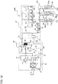
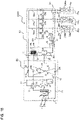
- FIG. 10 is a refrigerant circuit diagram illustrating an example of a refrigerant circuit configuration of a multi-split type air-conditioning apparatus 10000 according to Embodiment 6 of the present invention. Based on FIG. 10 , a refrigerant circuit configuration of the multi-split type air-conditioning apparatus 10000 will be described.
- the multi-split type air-conditioning apparatus 10000 according to Embodiment 6 includes an outdoor unit (also referred to as a heat source unit) 101, a relay unit 102, and a plurality of indoor units 103 (103a, 103b, and 103c). It should be noted that while description is given on the case where one outdoor unit is connected with one relay unit and three indoor units in this embodiment, the case of connecting two or more outdoor units, two or more relay units, and two or more indoor units is the same.
- the outdoor unit 101 includes therein a compressor 1 that compresses and discharges refrigerant, a four-way valve 2 that is a switching valve for switching the refrigerant flow direction in the outdoor unit 101, a gas header 9, an outdoor heat exchanger 8, a liquid header 7 (liquid header portions 7a and 7b), a shunt 6, an accumulator 44, and a third gas-liquid separator 140.
- the inlet of the third gas-liquid separator 140 is connected with a first connection pipe 21 provided inside a relay unit 102 described below.
- a liquid side outlet pipe 25 for discharging liquid refrigerant in which gas and liquid are separated by the third gas-liquid separator 140, or two-phase refrigerant in which the quality is adjusted, is connected with the four-way valve via a check valve 160.
- the check valve 160 allows liquid refrigerant to flow only from the third gas-liquid separator 140 to the four-way valve 2. Further, a gas side outlet pipe 26 for discharging gas refrigerant in which gas and liquid are separated by the third gas-liquid separator 140, is connected with the inlet or the inside of the accumulator 44 via a gas side bypass flow channel resistance 150 functioning as a flow rate control mechanism. In this way, it is configured that the refrigerant in the third gas-liquid separator 140 flows in one direction to the suction side of the compressor 1.
- the compressor 1, the four-way valve 2, the gas header 9, the outdoor heat exchanger 8, (the liquid header portions 7a and 7b), and the shunt 6 are connected in this order by the discharge pipe 31. Further, the outdoor heat exchanger 8 is connected with the relay unit 102 via the second connection pipe 22 narrower than the first connection pipe 21, by the refrigerant pipe 32 in which the check valve 190 is provided.
- the check valve 190 has a function of allowing refrigerant to flow only from the outdoor heat exchanger 8 to the second connection pipe 22.
- the liquid side outlet pipe 25 and the refrigerant pipe 32 are connected with each other by a short-circuit pipe 33 having a check valve 170 and a short-circuit pipe 34 having a check valve 180. Both the check valve 170 and the check valve 180 allow refrigerant to flow only from the liquid side outlet pipe 25 to the refrigerant pipe 32.
- the circuits having the check valves 160, 170, 180, and 190 constitute a flow channel switching circuit 35 on the outdoor unit side.
- the outlet of the accumulator 44 and the suction port of the compressor 1 are connected with each other by a suction pipe 36, and the four-way valve 2 and the accumulator 44 are connected with each other by a refrigerant pipe 37.
- the outdoor unit 101 is provided with a fan 12 (not shown in FIG. 10 , see FIG. 2 ) that supplies air (outdoor air) on which heat exchange is to be performed, to the outdoor heat exchanger 8.
- a fan 12 (not shown in FIG. 10 , see FIG. 2 ) that supplies air (outdoor air) on which heat exchange is to be performed, to the outdoor heat exchanger 8.
- the outdoor unit 101 and the relay unit 102 are connected with each other by the first connection pipe 21 that is a wide pipe, and the second connection pipe 22 that is a pipe narrower than the first connection pipe 21.
- the relay unit 102 includes a second gas-liquid separation device (intra-relay unit gas-liquid separation device) 50 connected to the middle of the second connection pipe 22.
- a gas phase portion of the second gas-liquid separator 50 is connected with branch pipes 21a, 21b, and 21c of the indoor units 103a, 103b, and 103c connected parallel to each other, via solenoid valves 120a, 120b, and 120c, respectively.
- the branch pipes 21a, 21b, and 21c are connected with indoor heat exchangers 1000a, 1000b, and 1000c of the indoor units 103a, 103b, and 103c. Further, the branch pipes 21a, 21b, and 21c are provided with the solenoid valves 130a, 130b, and 130c.
- a circuit configured of the solenoid valves 120a, 120b, 120c and solenoid valves 130a, 130b, and 130c is called a switching unit 104.
- liquid phase portion of the second gas-liquid separator 50 is connected with a second bypass pipe 23, and the second bypass pipe 23 is connected with the indoor units 103a, 103b, and 103c via branch pipes 22a, 22b, and 22c, respectively.
- the branch pipes 22a, 22b, and 22c are provided with first flow rate control devices 110a, 110b, and 110c.
- a third bypass pipe 24 branching from the first connection pipe 21 is provided, and the other end of the third bypass pipe 24 is connected with the second bypass pipe 23.
- a first heat exchanger 60 and a second heat exchanger 70 are provided between the second bypass pipe 23 and the third bypass pipe 24, for exchanging heat between refrigerant flowing in the second bypass pipe 23 and refrigerant flowing in the third bypass pipe 24, are provided.
- the second bypass pipe 23, located between the first heat exchanger 60 and second heat exchanger 70, is provided with an openable/closable third flow rate control device 85. Further, between the second heat exchanger 70 and the other end connecting portion of the third bypass pipe 24 (connecting portion with the second bypass pipe 23), an openable/closable second flow rate control device 90 (bypass pipe flow rate control device) is provided.
- the indoor units 103a, 103b, and 103c are connected with each other to allow refrigerant to circulate through the branch pipes 21a, 21b, and 21c branching from the first connection pipe 21 of the relay unit 102 and the branch pipes 22a, 22b, and 22c branching from the second bypass pipe 23.
- the respective indoor units 103a, 103b, and 103c include indoor heat exchangers 1000a, 1000b, and 1000c, and the openable/closable first flow rate control devices 110a, 110b, and 110c, respectively.
- the first flow rate control devices 110a, 110b, and 110c are connected in the vicinity of the indoor heat exchangers 1000a, 1000b, and 1000c, and at the time of cooling, they are controlled according to the degree of superheat of the outlet side of the indoor heat exchangers 1000a, 1000b, and 1000c, and at the time of heating, they are controlled according to the degree of subcooling.
- Operational actions at the time of various types of operation performed by the multi-split type air-conditioning apparatus 10000 will be described.
- Operational actions by the multi-split type air-conditioning apparatus 10000 include four operation modes, namely cooling, heating, cooling main, and heating main.
- a cooling operation mode is an operation mode in which all operating indoor units perform cooling
- a heating operation mode is an operation mode in which all operating indoor units perform heating.
- a cooling main operation mode is an operation mode in which an indoor unit performing cooling operation and an indoor unit performing heating operation are mixed, and the cooling load is larger than the heating load.
- a heating main operation mode is an operation mode in which an indoor unit performing cooling operation and an indoor unit performing heating operation are mixed, and the heating load is larger than the cooling load.
- the outdoor heat exchanger 8 is connected to the discharge side of the compressor 1, and acts as a condenser (radiator).
- the outdoor heat exchanger 8 is connected to the suction side of the compressor 1, and acts as an evaporator.
- the flow of refrigerant in each operation mode will be described.
- FIG. 11 is a refrigerant circuit diagram illustrating a flow of refrigerant at the time of heating operation in the multi-split type air-conditioning apparatus of Embodiment 6.
- description will be given on the case where all of the indoor units 103a, 103b, and 103c attempt to perform heating.
- the four-way valve 2 is switched such that the refrigerant discharged from the compressor 1 passes through the second connection pipe 22 to flow into the switching unit 104 configured of the solenoid valves 120a, 120b, and 120c and the solenoid valves 130a, 130b, and 130c, without bypassing through the outdoor heat exchanger 8 and the liquid header 7.
- the solenoid valves 130a, 130b, and 130c provided to the branch pipes 21a, 21b, and 21c are controlled to be in a closed state
- the solenoid valves 120a, 120b, and 120c provided to the pipes connected from the second connection pipe 22 to the indoor units 103a, 103b, and 103c are controlled to be in an open state.
- the pipes and devices shown by the solid lines indicate paths through which the refrigerant circulates, and the paths indicated by the dotted lines indicate that the refrigerant does not flow therethrough.
- the refrigerant in the low-temperature and low-pressure two-phase gas-liquid state having flowed out of the second flow rate control device 90, flows into the third gas-liquid separator 140 in the outdoor unit 101 via the third bypass pipe 24 and the first connection pipe 21.
- the gas refrigerant, in which gas and liquid are separated by the third gas-liquid separator 140 flows into the inlet or the inside of the accumulator 44 via the gas side outlet pipe 26 and the gas side bypass flow channel resistance 150.
- the two-phase refrigerant in which gas and liquid are separated and the quality is controlled by the third gas-liquid separator 140, flows from the liquid side outlet pipe 25 through the short circuit pipe 33 and the check valve 170, and then flows into the shunt 6.
- the two-phase refrigerant, flowing in the shunt 6, is supplied to the liquid header portion 7a and the liquid header portion 7b that are divided into two.
- the two-phase refrigerant, supplied to the liquid header portion 7a is allocated to the respective heat transfer tubes 15 connected with the liquid header portion 7a (respective heat transfer tubes 15 arranged in the upper divided region of the outdoor heat exchanger 8). Further, the two-phase refrigerant, supplied to the liquid header portion 7b, is allocated to the respective heat transfer tubes 15 connected with the liquid header portion 7b (respective heat transfer tubes 15 arranged in the lower divided portion of the outdoor heat exchanger 8).
- the refrigerant flowing in the outdoor heat exchanger 8 is heated, while cooling the outdoor air, to be low-temperature and low-pressure gas refrigerant.
- the low-temperature and low-pressure gas refrigerant having flowed out of the outdoor heat exchanger 8, passes through the four-way valve 2 via the gas header 9, and joins the gas refrigerant, in which gas and liquid are separated by the third gas-liquid separator 140, at the inlet or the inside of the accumulator 44, and flows into the compressor 1 and is compressed. Afterwards, the refrigerant circulates the same path as described above.
- FIG. 12 is a refrigerant circuit diagram illustrating a flow of refrigerant at the time of cooling operation in the multi-split type air-conditioning apparatus according to Embodiment 6 of the present invention.
- description will be given on the case where all of the indoor units 103a, 103b, and 103c attempt to perform cooling.
- the four-way valve 2 is switched such that the refrigerant, discharged from the compressor 1, flows into the outdoor heat exchanger 8.
- the solenoid valves 130a, 130b, and 130c connected with the indoor units 103a, 103b, and 103c are controlled to be in an open state
- the solenoid valves 120a, 120b, and 120c are controlled to be in a closed state.
- the pipes and devices shown by the solid lines indicate paths in which the refrigerant circulates, and the paths shown by the dotted lines indicate that refrigerant does not flow therethrough.
- the high-temperature and high-pressure gas refrigerant discharged from the compressor 1, flows into the outdoor heat exchanger 8 via the four-way valve 2. At this time, the refrigerant is cooled, while heating the outdoor air, to be medium-temperature and high-pressure liquid refrigerant.
- the liquid refrigerant cooled by the first heat exchanger 60 and the second heat exchanger 70 flows into the second branch portion 105 configured of the branch pipes 22a, 22b, and 22c, while allowing a part of the refrigerant to bypass to flow into the third bypass pipe 24.
- the high-pressure liquid refrigerant flowing in the second branch portion 105 branches at the second branch portion 105 and the respective portions of the refrigerant flow into the first flow rate control devices 110a, 110b, and 110c. Then, the high-pressure liquid refrigerant is throttled by the first flow rate control devices 110a, 110b, and 110c to be expanded and compressed to be in a low-temperature and low-pressure two-phase gas-liquid state.
- the gas refrigerant passing through the first connection pipe 21 flows into the third gas-liquid separator 140, and flows out while branching to the two paths, namely the gas side outlet pipe 26 and the liquid side outlet pipe 25.
- the gas refrigerant, flowing to the gas side outlet pipe 26, passes through the gas side bypass flow channel resistance 150 and flows into the inlet or the inside of the accumulator 44.
- the gas refrigerant, flowing to the liquid side outlet pipe 25, passes through the check valve 160 and flows into the accumulator 44 via the four-way valve 2.
- FIG. 13 is a refrigerant circuit diagram illustrating a flow of refrigerant at the time of heating main operation in the multi-split type air-conditioning apparatus according to Embodiment 6 of the present invention.
- the indoor unit 103c performs cooling and the indoor units 103a and 103b perform heating.
- the four-way valve 2 is switched such that the refrigerant discharged from the compressor 1 passes through the second connection pipe 22 and flows into the switching unit 104 configured of the solenoid valves 120a, 120b, and 120c and the solenoid valves 130a, 130b, and 130c.
- the solenoid valves 130a, 130b, and 120c connected with the indoor units 103a, 103b, and 103c are controlled to be in a closed state, and the solenoid valves 120a, 120b, and 130c are controlled to be in an open state.
- the pipes and the devices shown by the solid lines indicate paths in which refrigerant flows, and the paths shown by the dotted lines indicate that refrigerant does not flow therethrough.
- the refrigerant in the low-temperature and low-pressure two-phase gas-liquid state having flowed out of the first flow rate control device 110c, flows into the indoor heat exchanger 1000c. Then, the refrigerant is heated, while cooling the indoor air, to be low-temperature and low-pressure gas refrigerant.
- the residual of the high-pressure liquid refrigerant flowing from the indoor heat exchangers 1000a and 1000b, performing heating, to the second branch portion 105 flows into the second flow rate control device 90.
- the high-pressure liquid refrigerant is throttled by the second flow rate control device 90 to be expanded (decompressed) to be in a low-temperature and low-pressure two-phase gas-liquid.
- the refrigerant in the low-temperature and low-pressure two-phase gas-liquid state, having flowed out of the second flow rate control device 90 passes through the third bypass pipe 24 and flows into the first connection pipe 21, and joins the refrigerant in a low-temperature and low-pressure vapor state having flowing from the indoor heat exchanger 1000c that performs cooling.
- the two-phase refrigerant, in which gas and liquid are separated and the quality is controlled by the third gas-liquid separator 140 flows from the liquid side outlet pipe 25 through the short circuit pipe 33 and the check valve 170, into the shunt 6.
- the two-phase refrigerant flowing in the shunt 6 is supplied to the liquid header portion 7a and the liquid header portion 7b that are divided into two. Then, the two-phase liquid refrigerant, supplied to the liquid header portion 7a, is allocated to the respective heat transfer tubes 15 connected with the liquid header portion 7a (respective heat transfer tubes 15 arranged in the upper divided region of the outdoor heat exchanger 8).
- the two-phase refrigerant, supplied to the liquid header portion 7b, is allocated to the respective heat transfer tubes 15 connected with the liquid header portion 7b (respective heat transfer tubes 15 arranged in the lower divided portion of the outdoor heat exchanger 8).
- the refrigerant having flowed into the outdoor heat exchanger 8 absorbs heat from the outdoor air and is heated, while cooling the outdoor air, to be low-temperature and low-pressure gas refrigerant.
- the low-temperature and low-pressure gas refrigerant having flowed out of the outdoor heat exchanger 8, passes through the four-way valve 2, joins the gas refrigerant, in which gas and liquid are separated by the third gas-liquid separator 140, at the inlet or the inside of the accumulator 44, and the refrigerant flows into the compressor 1 and is compressed. At this time, by allowing a part of gas refrigerant to bypass by the third gas-liquid separator 140, it is possible to reduce a pressure loss of the outdoor heat exchanger 8.
- FIG. 14 is a refrigerant circuit diagram illustrating a flow of refrigerant at the time of cooling main operation in the multi-split type air-conditioning apparatus according to Embodiment 6 of the present invention.
- the indoor units 103b and 103c perform cooling and the indoor unit 103a performs heating.
- the four-way valve 2 is switched such that the refrigerant, discharged from the compressor 1, flows into the outdoor heat exchanger 8.
- the solenoid valves 120a, 130b, and 130c connected with the indoor units 103a, 103b, and 103c are controlled to be in an open state, and the solenoid valves 130a, 120b, and 120c are controlled to be in a closed state.
- the pipes and the devices shown by the solid lines indicate paths in which refrigerant flows, and the paths shown by the dotted lines indicate that refrigerant does not flow therethrough.
- the high-temperature and high-pressure gas refrigerant discharged from the compressor 1 flows into the outdoor heat exchanger 8 via the four-way valve 2. At this time, in the outdoor heat exchanger 8, the refrigerant is cooled while heating the outdoor air, remaining the amount of heat required for heating, to be in a medium-temperature and high-pressure two-phase gas-liquid state.
- the liquid refrigerant, separated by the second gas-liquid separator 50 flows into the first heat exchanger 60, and exchanges heat with the low-pressure refrigerant flowing in the third bypass pipe 24 to be cooled.
- the refrigerant having flowed out of the indoor heat exchanger 1000a that performs heating and the refrigerant having flowed out of the first heat exchanger 60 pass through the first flow rate control device 110a and the third flow rate control device 85, and the second heat exchanger 70, respectively, and join.
- the joined liquid refrigerant branches at the second branch portion 105 configured of the branch pipes 22a, 22b, and 22c, while allowing a portion of the refrigerant to bypass to flow into the third bypass pipe 24, and the respective portions of the refrigerant flow into the first flow rate control devices 110b and 110c of the indoor units 103b and 103c that perform cooling. Then, the high-pressure liquid refrigerant is throttled by the first flow rate control devices 110b and 110c and expanded and decompressed to be in a low-temperature and low-pressure two-phase gas-liquid state. Changes in the state of the respective portions of the refrigerant by the first flow rate control devices 110b and 110c are performed under a condition that enthalpy is constant.
- the sectional area of the flow channel from the third gas-liquid separator 140 to the accumulator 44 is increased, whereby it is possible to reduce a pressure loss in the path.
- the compressor suction temperature is maintained at a high level, and the performance of the compressor 1 is improved.
- the shunt 6 supplies, to the respective liquid header portions 7a and 7b, two-phase refrigerant of the amount corresponding to the divided regions of the outdoor heat exchanger 8 to which the respective liquid header portions 7a and 7b are connected.
- the amount of liquid refrigerant lifted upward by the gas refrigerant in the liquid header portion can be adjusted according to the distribution of the wind speed, and the refrigerant can be supplied to the divided region along the distribution of the wind speed. As such, performance of the outdoor heat exchanger 8 can be improved sufficiently.
- Embodiment 6 describes an example using the outdoor heat exchanger 8 and the liquid header 7 shown in Embodiment 1, the outdoor heat exchanger 8 and the liquid header 7 described in Embodiments 2 to 5 may be used. The effects described in Embodiments 2 to 5 can be achieved.
- first heat exchanger 60, the second heat exchanger 70, and the third flow rate control device 85, provided to the second bypass pipe 23, are used for increasing the degree of subcooling of the liquid refrigerant flowing out of the second gas-liquid separator 50.
- the first heat exchanger 60, the second heat exchanger 70, and the third flow rate control device 85 are not indispensable configurations in the present invention.
- the multi-split type air-conditioning apparatus 10000 in which the present invention can be implemented, is not limited to the multi-split type air-conditioning apparatus 10000 described in Embodiment 6. It may be configured as described below. It should be noted that the configurations not described in Embodiment 7 are the same as those in any of Embodiments 1 to 6, and the configurations that are the same as those of the above-described embodiments are denoted by the same reference numerals.
- the relay unit includes a plurality of intermediate heat exchangers functioning as the condensers when the indoor units perform heating, and a plurality of first flow rate control devices connected with the respective intermediate heat exchangers and functioning as the expansion valves.
- the indoor unit includes an indoor heat exchanger connected with the intermediate heat exchanger.
- a closed first refrigerant circuit is configured, and to allow refrigerant other than the above-described refrigerant to flow in the indoor unit and the intermediate heat exchanger of the relay unit, a closed second refrigerant circuit is configured.
- FIG. 15 is a refrigerant circuit diagram illustrating an example of a refrigerant circuit of the multi-split type air-conditioning apparatus according to Embodiment 7 of the present invention. States of the four-way valve 2 and the solenoid valves 120a, 120b, 120c, 130a, 130b, and 130c in the respective operation modes will be described below.
- FIG. 15 shows the orientation of the four-way valve 2 at the time of cooling operation.
- the solenoid valves 120a, 120b, and 120c in the relay unit 102 are controlled to be in a closed state, and the solenoid valves 130a, 130b, and 130c are controlled to be in an open state.
- the four-way valve 2 is switched such that the refrigerant flows from the compressor 1 to the indoor unit 103, and the solenoid valves 120a, 120b, and 120c in the relay unit 102 are controlled to be in an open state, and the solenoid valves 130a, 130b, and 130c are controlled to be in a closed state.
- the four-way valve 2 is switched such that the refrigerant flows from the compressor 1 to the outdoor heat exchanger 8, the solenoid valves 130a, 130b, and 120c in the relay unit 102 are controlled to be in an open state, and the solenoid valves 120a, 120b, and 130c are controlled to be in a closed state.
- the four-way valve 2 is switched such that the refrigerant flows from the compressor 1 to the indoor unit 103, the solenoid valves 120a, 120b, and 130c in the relay unit 102 are controlled to be in an open state, and the solenoid valves 130a, 130b, and 120c are controlled to be in a closed state.
- a relay unit side refrigerant circuit 41 (41a, 41b, and 41c) and an indoor unit side refrigerant circuit 42 (42a, 42b, and 42c), in which different kinds of refrigerants circulate as described below, are configured, and an intermediate heat exchanger 40 (40a, 40b, and 40c) is interposed between the two refrigerant circuits 41 and 42.
- branch pipes 22a, 22b, and 22c and the branch pipes 21a, 21b, and 21c are connected with each other such that the refrigerant circulates the outdoor unit 101 and the intermediate heat exchanger 40 (40a, 40b, and 40c) of the relay unit 102 connected with the outdoor unit 101 by the first connection pipe 21 and the second connection pipe 22, to form the closed refrigerant circuits 41a, 41b, and 41c. Then, the refrigerant circuits 41a, 41b, and 41c are provided with first flow rate control devices 110a, 110b, and 110c, respectively.
- the refrigerant circuits 42a, 42b, and 42c are configured to be closed such that refrigerant (water or antifreeze, for example) other than the above-described refrigerant circulates the indoor heat exchangers 1000a, 1000b, and 1000c of the indoor units 103a, 103b, and 103c and the intermediate heat exchangers 40 (40a, 40b, and 40c) of the relay unit 102.
- refrigerant water or antifreeze, for example
- the refrigerant circuits 42a, 42b, and 42c are provided with pumps 43a, 43b, and 43c, and the intermediate heat exchangers 40a, 40b, and 40c are interposed between the relay unit side refrigerant circuits 41a, 41b, and 41c and the indoor unit side refrigerant circuits 42a, 42b, and 42c, to allow the refrigerant flowing in the refrigerant circuit 41 and the refrigerant flowing in the refrigerant circuit 42 to exchange heat with each other by the intermediate heat exchanger 40.
- the other functions and configurations are the same as those of Embodiment 6.
- the third gas-liquid separator 140 is provided to the outdoor unit 101.
- the third gas-liquid separator 140 may be provided to the relay unit 102.
- an example in which the installment position of the third gas-liquid separator 140 is changed in the multi-split type air-conditioning apparatus 10000 shown in Embodiment 6 will be given.
- FIG. 16 is a refrigerant circuit diagram illustrating an example of a refrigerant circuit configuration of a multi-split type air-conditioning apparatus according to Embodiment 8 of the present invention.
- the third gas-liquid separator 140 is connected to the middle of the first connection pipe 21, and the third gas-liquid separator 140 is installed in the relay unit 102.
- the third gas-liquid separator 140 By installing the third gas-liquid separator 140 in the relay unit 102 in this way, as gas refrigerant or liquid refrigerant, in which gas and liquid are separated, flows in the first connection pipe 21, it is possible to significantly reduce a pressure loss caused by the extension pipe between the outdoor unit 101 and the relay unit 102.
- the other functions and configurations are the same as those of Embodiment 6 and Embodiment 7.
- gas refrigerant in which gas and liquid are separated is allowed to bypass as gas refrigerant by the third gas-liquid separator 140, and liquid refrigerant, in which gas and liquid are separated, flows out as a zeotropic refrigerant mixture in which composition ratio is biased to refrigerant having a high boiling point with the inlet of the third gas-liquid separator 140.
- zeotropic refrigerant mixture for example, R404A, R407C, or the like
- single refrigerant for example, R22 or the like
- azeotropic refrigerant mixture for example, R502, R507A, or the like
- Embodiments 1 to 9 details of a connection configuration between the liquid header portion and the outdoor heat exchanger 8 (in more detail, heat transfer tube 15) are not described particularly.
- the configurations not described in Embodiment 10 are the same as those in any of Embodiments 1 to 9, and the configurations that are the same as those of the above-described embodiments are denoted by the same reference numerals.
- FIG. 17 illustrates an outdoor heat exchanger of an air-conditioning apparatus according to Embodiment 10 of the present invention. It should be noted that in FIG. 17 , distribution of the wind speed passing through the outdoor heat exchanger 8 and the amount of refrigerant (refrigerant distribution) supplied to the outdoor heat exchanger 8 are also shown.
- respective liquid header portions 7a and 7b and the heat transfer tubes 15 of the outdoor heat exchanger 8 are connected by a plurality of branch pipes 45.
- the liquid header portion 7a arranged in an upper portion (connected with the heat transfer tubes 15 of a divided region having larger distribution of wind speed) is connected with the heat transfer tubes 15 of the outdoor heat exchanger 8 by the branch pipes 45a.
- the liquid header portion 7b arranged in a lower portion (connected with the heat transfer tubes 15 of a divided region having a smaller distribution of wind speed) is connected with the heat transfer tubes 15 of the outdoor heat exchanger 8 by the branch pipes 45b.
- the liquid header portion 7a arranged in the upper portion has a configuration in which a larger number of branch pipes 45 are connected to a region of the same area.
- the number of the branch pipes 45a is larger than the number of the branch pipes 45b.
- the gas header 9 connected to a position which is a refrigerant outflow side of the outdoor heat exchanger 8 is divided into a plurality of gas header portions in the up and down direction.
- the gas header 9 is divided into two gas header portions 9a and 9b in the up and down direction. Further, the gas header portions 9a and 9b are connected with the four-way valve 2 by a refrigerant outlet pipe 46.
- the gas header portion 9a is connected with the four-way valve 2 by a refrigerant outlet pipe 46a.
- the gas header portion 9b is connected with the four-way valve 2 by a refrigerant outlet pipe 46b.
- the refrigerant outlet pipe 46 (refrigerant outlet pipes 46a and 46b) connects the gas header 9 (gas header portions 9a and 9b) and the suction side of the compressor 1, when the outdoor heat exchanger 8 functions as an evaporator.
- the liquid header portion 7a arranged in the upper portion has a configuration in which a larger number of branch pipes 45 are connected to a region of the same area.
- the flow resistance of the refrigerant, flowing into the heat transfer tube 15 of a divided region having larger distribution of the wind speed is smaller. Accordingly, a larger amount of refrigerant can be supplied to a divided region having larger wind speed distribution.
- largely biased wind speed distribution can be managed.
- Embodiments 1 to 10 by configuring the gas header 9 as described below, it is possible to supply a larger amount of refrigerant to a divided region having larger wind speed distribution. It should be noted that the configurations not described in Embodiment 11 are the same as those in any of Embodiments 1 to 10, and the configurations that are the same as those of the above-described embodiments are denoted by the same reference numerals.
- FIG. 18 illustrates an outdoor heat exchanger of an air-conditioning apparatus according to Embodiment 11 of the present invention. It should be noted that FIG. 18 also illustrates distribution of the wind speed passing through the outdoor heat exchanger 8 and the amount of refrigerant (refrigerant distribution) supplied to the outdoor heat exchanger 8.
- the gas header 9 is divided into a plurality of gas header portions in the up and down direction.
- the gas header 9 is divided into two gas header portions 9a and 9b in the up and down direction.
- the inner diameter of the gas header portion 9a arranged in an upper portion is larger than the inner diameter of the gas header portion 9b arranged in a lower portion (connected with the heat transfer tubes 15 of a divided region of smaller wind speed distribution).
- Embodiments 1 to 11 even by configuring the gas header 9 as described below, it is possible to supply a larger amount of refrigerant to a divided region having larger wind speed distribution. It should be noted that the configurations not described in Embodiment 12 are the same as those in any of Embodiments 1 to 11, and the configurations that are the same as those of the above-described embodiments are denoted by the same reference numerals.
- FIG. 19 illustrates an outdoor heat exchanger of an air-conditioning apparatus according to Embodiment 12 of the present invention. It should be noted that in FIG. 19 , distribution of the wind speed passing through the outdoor heat exchanger 8 and the amount of refrigerant (refrigerant distribution) supplied to the outdoor heat exchanger 8 are also shown.
- the gas header 9 is divided into a plurality of gas header portions in the up and down direction.
- the gas header 9 is divided into two gas header portions 9a and 9b in the up and down direction.
- a larger number of refrigerant outlet pipes 46 are connected, compared with that of the gas header portion 9b arranged in a lower portion (connected with the heat transfer tubes 15 of a divided region having smaller wind speed distribution).
Landscapes
- Engineering & Computer Science (AREA)
- Physics & Mathematics (AREA)
- Mechanical Engineering (AREA)
- Thermal Sciences (AREA)
- General Engineering & Computer Science (AREA)
- Other Air-Conditioning Systems (AREA)
- Air Conditioning Control Device (AREA)
Claims (14)
- Appareil de climatisation (300, 10000), comprenant:- un cycle de réfrigération incluant un compresseur (1), un condenseur, une soupape de détente (4), un échangeur de chaleur extérieur (8) servant d'évaporateur et un collecteur de liquide (7) relié à une position qui est un côté entrée de réfrigérant de l'échangeur de chaleur extérieur (8) lorsque l'échangeur de chaleur extérieur (8) sert d'évaporateur;- un ventilateur extérieur (12) configuré pour fournir de l'air à l'échangeur de chaleur extérieur (8),- l'échangeur de chaleur extérieur (8) comprenant des tubes de transfert de chaleur (15), l'échangeur de chaleur extérieur (8) étant prévu sur un boîtier (13) d'une unité extérieure (100, 101) de telle sorte que les tubes de transfert de chaleur (15) sont disposés en parallèle dans une direction ascendante et descendante,- l'air aspiré dans le boîtier (13) de l'unité extérieure (100, 101) par le ventilateur extérieur (12) étant déchargé depuis une partie supérieure du boîtier (13) après avoir échangé de la chaleur dans l'échangeur de chaleur extérieur (8),- le collecteur de liquide (7) étant divisé en une pluralité de parties de collecteur de liquide (7a, 7b, 7c) dans la direction ascendante et descendante,- chacune des parties de collecteur de liquide (7a, 7b, 7c) étant configurée pour être reliée à chacun des tubes de transfert de chaleur (15) des régions divisées formées en divisant l'échangeur de chaleur extérieur (8) dans la direction ascendante et descendante,- un premier séparateur gaz-liquide (5) configuré pour séparer le réfrigérant à deux phases, s'écoulant de la soupape de détente (4), en réfrigérant gazeux et réfrigérant liquide;- une dérivation (10) reliant le premier séparateur gaz-liquide (5) et un côté aspiration du compresseur (1), la dérivation (10) étant configurée pour ajuster une quantité du réfrigérant gazeux, séparé par le premier séparateur gaz-liquide (5), à renvoyer au côté aspiration du compresseur (1); et- un shunt (6) reliant le premier séparateur gaz-liquide (5) et chacune des parties de collecteur de liquide (7a, 7b, 7c),
dans lequel le shunt (6) est configuré pour fournir le réfrigérant à deux phases, dans lequel la quantité de réfrigérant gazeux dans le réfrigérant à deux phases est ajustée par le premier séparateur gaz-liquide (5), à chacune des parties de collecteur de liquide (7a, 7b, 7c) et est configuré pour fournir une plus grande quantité du réfrigérant à deux phases à l'une des parties de collecteur de liquide (7a, 7b, 7c) reliée à la région divisée de la partie supérieure de l'échangeur de chaleur extérieur (8) ayant une plus grande quantité d'air, qu'à une autre des parties de collecteur de liquide (7a, 7b, 7c) reliée à la région divisée de la partie inférieure de l'échangeur de chaleur extérieur (8) ayant une plus petite quantité d'air. - Appareil de climatisation (300, 10000) selon la revendication 1,dans lequel, dans au moins certaines parties de collecteur de liquide (7a, 7b) des parties de collecteur de liquide (7a, 7b, 7c),lorsqu'il est défini que l'une des parties de collecteur de liquide (7a, 7b) est une première partie de collecteur de liquide (7a), une autre des parties de collecteur de liquide (7a, 7b) disposée sous la première partie de collecteur de liquide (7a) est une deuxième partie de collecteur de liquide (7b), et qu'un diamètre intérieur de la première partie de collecteur de liquide (7a) où le flux massique de réfrigérant de la première partie de collecteur de liquide (7a) et le flux massique de réfrigérant de la deuxième partie de collecteur de liquide (7b) sont identiques est D1,un diamètre intérieur D de la première partie de collecteur de liquide (7a) satisfait à D < D 1.
- Appareil de climatisation (300, 10000) selon la revendication 1,
dans lequel un diamètre intérieur de l'une des parties de collecteur de liquide (7a, 7b) reliée à un tube de transfert de chaleur (15) des tubes de transfert de chaleur (15) dans l'une des régions divisées, dans laquelle la vitesse du vent est plus grande, est plus petit qu'un diamètre intérieur d'une autre des parties de collecteur de liquide (7b, 7c) reliée à un tube de transfert de chaleur (15) des tubes de transfert de chaleur (15) dans une autre des régions divisées dans laquelle la vitesse du vent est plus petite que la vitesse du vent de ladite une des régions divisées. - Appareil de climatisation (300, 10000) selon l'une quelconque des revendications 1 à 3,
dans lequel, comme un diamètre intérieur d'un canal d'écoulement (6b) du shunt (6) relié à chacune des parties de collecteur de liquide (7a, 7b, 7c) est formé pour être différent pour chacune des parties de collecteur de liquide (7a, 7b, 7c), le shunt (6) est configuré pour changer la quantité de réfrigérant à deux phases fournie à chacune des parties de collecteur de liquide (7a, 7b, 7c). - Appareil de climatisation (300, 10000) selon l'une quelconque des revendications 1 à 3,
dans lequel, comme une longueur d'un canal d'écoulement (6b) du shunt (6) relié à chacune des parties de collecteur de liquide (7a, 7b, 7c) est formée pour être différente pour chacune des parties de collecteur de liquide (7a, 7b, 7c), le shunt (6) est configuré pour changer la quantité de réfrigérant à deux phases fournie à chacune des parties de collecteur de liquide (7a, 7b, 7c). - Appareil de climatisation (300, 10000) selon l'une quelconque des revendications 1 à 5, comprenant en outre:- un premier tuyau de dérivation (10a) et un mécanisme de commande de débit (11) constituant la dérivation (10), le premier tuyau de dérivation (10a) reliant le premier séparateur gaz-liquide (5) et le côté aspiration du compresseur (1) et permettant au réfrigérant gazeux séparé par le premier séparateur gaz-liquide (5) de retourner au côté aspiration du compresseur (1), le mécanisme de commande de débit (11) ajustant un débit du réfrigérant gazeux s'écoulant dans le premier tuyau de dérivation (10a); et- un dispositif de commande (20) configuré pour commander la quantité d'air du ventilateur extérieur (12) et un degré d'ouverture du mécanisme de commande de débit (11),
dans lequel le dispositif de commande (20) diminue le degré d'ouverture du mécanisme de commande de débit (11) lorsqu'il augmente la quantité d'air du ventilateur extérieur (12) et augmente le degré d'ouverture du mécanisme de commande de débit (11) lorsqu'il diminue la quantité d'air du ventilateur extérieur (12). - Appareil de climatisation (10000) selon l'une quelconque des revendications 1 à 6, comprenant en outre:- l'unité extérieure (101) incluant au moins le compresseur (1), une vanne à quatre voies (2), le collecteur de liquide (7) divisé en la pluralité de parties de collecteur de liquide (7a, 7b, 7c) dans la direction ascendante et descendante, le shunt (6), l'échangeur de chaleur extérieur (8) et le ventilateur extérieur (12);- une unité de relais (102) reliée à l'unité extérieure (101) par un premier tuyau de liaison (21) et un deuxième tuyau de liaison (22);- une pluralité d'unités intérieures (103) présentant chacune au moins un échangeur de chaleur intérieur (1000a, 1000b, 1000c), les unités intérieures (103) étant reliées à l'unité de relais (102) en parallèle les unes avec les autres,- l'unité extérieure (101) incluant un premier chemin guidant le réfrigérant déchargé du compresseur (1) vers le deuxième tuyau de liaison (22) via la vanne à quatre voies (2), le collecteur de liquide (7) et l'échangeur de chaleur extérieur (8) selon des modes de fonctionnement respectifs incluant : refroidissement, chauffage, principalement en refroidissement et principalement en chauffage, et un deuxième chemin guidant le réfrigérant vers le deuxième tuyau de liaison (22) via la vanne à quatre voies (2) sans passer par le collecteur de liquide (7) et l'échangeur de chaleur extérieur (8),- l'unité de relais (102) incluant un deuxième séparateur gaz-liquide (50) relié à un milieu du deuxième tuyau de liaison (22), une unité de commutation (104) configurée pour relier sélectivement chacune des unités intérieures (103) et l'un du premier tuyau de liaison (21) et du deuxième tuyau de liaison (22), un deuxième tuyau de dérivation (23) reliant le deuxième séparateur gaz-liquide (50) et chacune des unités intérieures (103), un troisième tuyau de dérivation (24) reliant le premier tuyau de liaison (21) et le deuxième tuyau de dérivation (23), et un dispositif de commande de débit de tuyau de dérivation (90) interposé dans le troisième tuyau de dérivation (24) et servant de soupape de détente (4),- un troisième séparateur gaz-liquide (140) relié au premier tuyau de liaison (21) et servant de premier séparateur gaz-liquide (5) dans un mode de fonctionnement en chauffage et un mode de fonctionnement principalement en chauffage;- un tuyau de sortie côté gaz (26) et un mécanisme de commande de débit (150) reliant le troisième séparateur gaz-liquide (140) et le côté aspiration du compresseur (1) et servant de dérivation (10) dans le mode de fonctionnement en chauffage et le mode de fonctionnement principalement en chauffage; et- un troisième chemin pour fournir du réfrigérant à deux phases, dans lequel la quantité de réfrigérant gazeux dans le réfrigérant à deux phases est ajustée par le troisième séparateur gaz-liquide (140), au shunt (6) dans le mode de fonctionnement en chauffage et le mode de fonctionnement principalement en chauffage.
- Appareil de climatisation (10000) selon la revendication 7,
dans lequel le troisième séparateur gaz-liquide (140) est prévu sur l'unité de relais (102). - Appareil de climatisation (10000) selon la revendication 7 ou 8,
dans lequel l'unité intérieure (103) inclut un échangeur de chaleur intérieur (1000a, 1000b, 1000c) servant de condenseur lorsque l'unité intérieure (103) effectue un chauffage et un premier dispositif de commande de débit (110a, 110b, 110c) servant de soupape de détente (4). - Appareil de climatisation (10000) selon la revendication 7 ou 8,dans lequel l'unité de relais (102) inclut une pluralité d'échangeurs de chaleur intermédiaires (40) servant chacun de condenseur lorsque l'unité intérieure (103) effectue un chauffage et une pluralité de premiers dispositifs de commande de débit (110a, 110b, 110c) reliés chacun à chacun des échangeurs de chaleur intermédiaires (40) et servant de soupape de détente (4),l'unité intérieure (103) inclut un échangeur de chaleur intérieur (1000a, 1000b, 1000c) relié aux échangeurs de chaleur intermédiaires (40),un premier circuit de réfrigérant (41) qui est fermé est configuré pour permettre à un type de réfrigérant de s'écouler dans l'unité extérieure (101) et les échangeurs de chaleur intermédiaires (40) de l'unité de relais (102), etun deuxième circuit de réfrigérant (42) qui est fermé est configuré pour permettre à un autre type de réfrigérant de s'écouler dans l'unité intérieure (103) et les échangeurs de chaleur intermédiaires (40) de l'unité de relais (102).
- Appareil de climatisation (300, 10000) selon l'une quelconque des revendications 1 à 10,
dans lequel le réfrigérant s'écoulant dans l'unité extérieure (100, 101) est un mélange réfrigérant zéotrope. - Appareil de climatisation (300, 10000) selon l'une quelconque des revendications 1 à 11,comprenant en outre une pluralité de tuyaux de branchement (45) reliant les parties de collecteur de liquide respectives (7a, 7b, 7c) et les tubes de transfert de chaleur (15) de l'échangeur de chaleur extérieur (8),dans lequel la partie de collecteur de liquide (7a) reliée à la région divisée dans laquelle la vitesse du vent est plus grande présente un plus grand nombre de tuyaux de branchement (45) reliés à une région de même taille, par rapport à la partie de collecteur de liquide (7b) reliée à la région divisée dans laquelle la vitesse du vent est plus petite.
- Appareil de climatisation (300, 10000) selon l'une quelconque des revendications 1 à 12, comprenant en outreun collecteur de gaz (9) relié à une position qui est un côté sortie de réfrigérant de l'échangeur de chaleur extérieur (8) lorsque l'échangeur de chaleur extérieur (8) sert d'évaporateur,dans lequel le collecteur de gaz (9) est divisé en une pluralité de parties de collecteur de gaz (9a, 9b) dans la direction ascendante et descendante,un diamètre intérieur d'une partie de collecteur de gaz (9a) de la pluralité de parties de collecteur de gaz (9a, 9b) reliée à un tube de transfert de chaleur (15) des tubes de transfert de chaleur (15) de l'une des régions divisées, dans laquelle la vitesse du vent est plus grande, est plus grand qu'un diamètre intérieur d'une partie de collecteur de gaz (9b) de la pluralité de parties de collecteur de gaz (9a, 9b) reliée à un tube de transfert de chaleur (15) des tubes de transfert de chaleur (15) d'une autre des régions divisées dans laquelle la vitesse du vent est plus petite que la vitesse du vent de l'une des régions divisées.
- Appareil de climatisation (300, 10000) selon l'une quelconque des revendications 1 à 13, comprenant en outre:- un collecteur de gaz (9) relié à une position qui est un côté sortie de réfrigérant de l'échangeur de chaleur extérieur (8) lorsque l'échangeur de chaleur extérieur (8) sert d'évaporateur; et- une pluralité de tuyaux de sortie de réfrigérant (46) reliant le collecteur de gaz (9) et le côté aspiration du compresseur (1) lorsque l'échangeur de chaleur extérieur (8) sert d'évaporateur,dans lequel le collecteur de gaz (9) est divisé en une pluralité de parties de collecteur de gaz (9a, 9b) dans la direction ascendante et descendante, etune partie de collecteur de gaz (9a) de la pluralité de parties de collecteur de gaz (9a, 9b) reliée à un tube de transfert de chaleur (15) des tubes de transfert de chaleur (15) de l'une des régions divisées, dans laquelle la vitesse du vent est plus grande, présente un plus grand nombre de tuyaux de sortie de réfrigérant (46) par rapport à une partie de collecteur de gaz (9b) de la pluralité de parties de collecteur de gaz (9a, 9b) reliée à un tube de transfert de chaleur (15) des tubes de transfert de chaleur (15) d'une autre des régions divisées dans laquelle la vitesse du vent est plus petite que la vitesse du vent de l'une des régions divisées.
Applications Claiming Priority (2)
| Application Number | Priority Date | Filing Date | Title |
|---|---|---|---|
| JP2014102954 | 2014-05-19 | ||
| PCT/JP2015/059095 WO2015178097A1 (fr) | 2014-05-19 | 2015-03-25 | Dispositif de climatisation |
Publications (3)
| Publication Number | Publication Date |
|---|---|
| EP3147591A1 EP3147591A1 (fr) | 2017-03-29 |
| EP3147591A4 EP3147591A4 (fr) | 2018-01-31 |
| EP3147591B1 true EP3147591B1 (fr) | 2022-04-13 |
Family
ID=54553774
Family Applications (1)
| Application Number | Title | Priority Date | Filing Date |
|---|---|---|---|
| EP15796237.4A Active EP3147591B1 (fr) | 2014-05-19 | 2015-03-25 | Dispositif de climatisation |
Country Status (5)
| Country | Link |
|---|---|
| US (1) | US10976085B2 (fr) |
| EP (1) | EP3147591B1 (fr) |
| JP (1) | JP6058219B2 (fr) |
| CN (1) | CN106461296B (fr) |
| WO (1) | WO2015178097A1 (fr) |
Families Citing this family (22)
| Publication number | Priority date | Publication date | Assignee | Title |
|---|---|---|---|---|
| CN104748261B (zh) * | 2015-03-31 | 2019-12-03 | 广东美的暖通设备有限公司 | 多联机系统 |
| JP6520353B2 (ja) * | 2015-04-27 | 2019-05-29 | ダイキン工業株式会社 | 熱交換器及び空気調和機 |
| JP6742112B2 (ja) * | 2016-02-29 | 2020-08-19 | 三菱重工サーマルシステムズ株式会社 | 熱交換器及び空気調和機 |
| JP2017223405A (ja) * | 2016-06-15 | 2017-12-21 | 日立ジョンソンコントロールズ空調株式会社 | 室外機および冷凍サイクル装置 |
| CN106196507A (zh) * | 2016-08-19 | 2016-12-07 | 芜湖美智空调设备有限公司 | 空调器和空调器的控制方法 |
| WO2018047330A1 (fr) * | 2016-09-12 | 2018-03-15 | 三菱電機株式会社 | Climatiseur |
| US20190234626A1 (en) * | 2016-09-12 | 2019-08-01 | Mitsubishi Electric Corporation | Header, heat exchanger, and air-conditioning apparatus |
| WO2018047511A1 (fr) | 2016-09-12 | 2018-03-15 | 三菱電機株式会社 | Échangeur de chaleur et climatiseur |
| EP3605000B1 (fr) | 2017-03-24 | 2023-01-11 | Mitsubishi Electric Corporation | Dispositif de climatisation |
| CN110709648B (zh) * | 2017-06-13 | 2021-06-22 | 三菱电机株式会社 | 空调装置 |
| CN109114838B (zh) * | 2017-06-22 | 2021-07-06 | 青岛海尔新能源电器有限公司 | 一种空气源热泵系统、热水器及控制方法 |
| WO2019021457A1 (fr) * | 2017-07-28 | 2019-01-31 | 三菱電機株式会社 | Distributeur de réfrigérant et dispositif de pompe à chaleur doté de ce distributeur |
| US11333366B2 (en) * | 2017-09-04 | 2022-05-17 | Mitsubishi Electric Corporation | Temperature adjustment apparatus, intermediary apparatus, load apparatus, and refrigeration cycle apparatus |
| CN107763774A (zh) * | 2017-11-09 | 2018-03-06 | 青岛海尔空调器有限总公司 | 空调制冷循环系统及空调器 |
| CN111373205B (zh) * | 2017-11-29 | 2021-08-10 | 三菱电机株式会社 | 空调机 |
| CN110686429A (zh) * | 2018-07-04 | 2020-01-14 | 浙江盾安热工科技有限公司 | 微通道换热器 |
| WO2020065999A1 (fr) * | 2018-09-28 | 2020-04-02 | 三菱電機株式会社 | Unité extérieure pour dispositif à cycle frigorifique, dispositif à cycle frigorifique, et dispositif de climatisation |
| JP7255215B2 (ja) * | 2019-02-06 | 2023-04-11 | 株式会社デンソー | 熱交換器 |
| CN110082066B (zh) * | 2019-05-29 | 2024-07-12 | 天津商业大学 | 受下游非均匀换热影响的分流性能测试实验系统 |
| JP6939869B2 (ja) * | 2019-11-14 | 2021-09-22 | ダイキン工業株式会社 | 熱交換器 |
| CN114938658B (zh) * | 2020-01-23 | 2024-07-05 | 三菱电机株式会社 | 制冷循环装置的室外机 |
| CN112628890A (zh) * | 2020-12-21 | 2021-04-09 | 青岛海尔空调电子有限公司 | 热泵系统及空调器 |
Family Cites Families (40)
| Publication number | Priority date | Publication date | Assignee | Title |
|---|---|---|---|---|
| JPH07318276A (ja) * | 1994-05-19 | 1995-12-08 | Matsushita Refrig Co Ltd | フィン付き蒸発器 |
| DE69533120D1 (de) * | 1994-05-30 | 2004-07-15 | Mitsubishi Electric Corp | Kühlmittelumlaufsystem |
| JP3216960B2 (ja) * | 1994-09-19 | 2001-10-09 | 株式会社日立製作所 | 空気調和機の室外機、室内機及びそれらに用いられる冷媒分配器 |
| JP3219014B2 (ja) | 1997-03-27 | 2001-10-15 | ダイキン工業株式会社 | 空調機用熱交換器 |
| KR100332773B1 (ko) * | 1999-09-13 | 2002-04-17 | 구자홍 | 히트 펌프의 증발기 유량 분배장치 |
| JP4180801B2 (ja) | 2001-01-11 | 2008-11-12 | 三菱電機株式会社 | 冷凍空調サイクル装置 |
| JP4554144B2 (ja) * | 2001-06-18 | 2010-09-29 | 昭和電工株式会社 | 蒸発器 |
| JP2004239592A (ja) * | 2002-12-11 | 2004-08-26 | Calsonic Kansei Corp | 車両用熱交換器 |
| US7610951B2 (en) * | 2003-08-06 | 2009-11-03 | Shell Oil Company | Apparatus and process for cooling hot gas |
| WO2006013834A1 (fr) * | 2004-08-02 | 2006-02-09 | Daikin Industries, Ltd. | Appareil de congélation |
| JP4810203B2 (ja) * | 2004-11-30 | 2011-11-09 | 昭和電工株式会社 | 熱交換器 |
| JP4922669B2 (ja) * | 2006-06-09 | 2012-04-25 | 日立アプライアンス株式会社 | 空気調和機及び空気調和機の熱交換器 |
| JP4766256B2 (ja) * | 2006-07-24 | 2011-09-07 | 株式会社富士通ゼネラル | 空気調和機の制御方法 |
| KR101157799B1 (ko) * | 2007-11-30 | 2012-06-20 | 다이킨 고교 가부시키가이샤 | 냉동 장치 |
| JP5018823B2 (ja) | 2008-07-22 | 2012-09-05 | ブラザー工業株式会社 | シート搬送装置および画像形成装置 |
| JP2010101552A (ja) * | 2008-10-23 | 2010-05-06 | Sanden Corp | ガスインジェクション冷凍システム |
| JP5071685B2 (ja) * | 2008-12-01 | 2012-11-14 | 株式会社富士通ゼネラル | 空気調和機 |
| KR20100081621A (ko) * | 2009-01-06 | 2010-07-15 | 엘지전자 주식회사 | 공기조화기 및 공기조화기의 제상운전방법 |
| KR20110139283A (ko) * | 2009-03-19 | 2011-12-28 | 다이킨 고교 가부시키가이샤 | 공기 조화 장치 |
| JP2012021679A (ja) * | 2010-07-13 | 2012-02-02 | Mitsubishi Electric Corp | 冷媒分配器、それを備えた熱交換器、及び、その熱交換器を搭載した空気調和機 |
| KR101233209B1 (ko) * | 2010-11-18 | 2013-02-15 | 엘지전자 주식회사 | 히트 펌프 |
| JP2012193872A (ja) | 2011-03-15 | 2012-10-11 | Daikin Industries Ltd | 熱交換器および空気調和機 |
| DK177329B1 (en) * | 2011-06-16 | 2013-01-14 | Advansor As | Refrigeration system |
| JP5257491B2 (ja) * | 2011-06-30 | 2013-08-07 | ダイキン工業株式会社 | 冷凍装置の室外機 |
| KR101288745B1 (ko) * | 2011-10-27 | 2013-07-23 | 엘지전자 주식회사 | 공기조화기 |
| US9377236B2 (en) | 2011-11-21 | 2016-06-28 | Hilll Phoenix, Inc. | CO2 refrigeration system with hot gas defrost |
| WO2013084501A1 (fr) * | 2011-12-09 | 2013-06-13 | ダイキン工業株式会社 | Dispositif de réfrigération de conteneur |
| EP2629030A1 (fr) * | 2011-12-12 | 2013-08-21 | Samsung Electronics Co., Ltd | Climatiseur |
| JP5929450B2 (ja) * | 2012-04-16 | 2016-06-08 | 三菱電機株式会社 | 冷凍サイクル装置 |
| KR101425043B1 (ko) * | 2012-07-26 | 2014-08-01 | 엘지전자 주식회사 | 실외 열교환기 |
| JP5772904B2 (ja) * | 2013-09-02 | 2015-09-02 | ダイキン工業株式会社 | 熱回収型冷凍装置 |
| JP5549773B1 (ja) * | 2013-09-30 | 2014-07-16 | 株式会社富士通ゼネラル | 空気調和装置 |
| JP5747968B2 (ja) * | 2013-10-07 | 2015-07-15 | ダイキン工業株式会社 | 熱回収型冷凍装置 |
| JP6180338B2 (ja) * | 2014-01-29 | 2017-08-16 | ジョンソンコントロールズ ヒタチ エア コンディショニング テクノロジー(ホンコン)リミテッド | 空気調和機 |
| KR101550549B1 (ko) * | 2014-08-01 | 2015-09-04 | 엘지전자 주식회사 | 공기 조화기 |
| EP3015793B1 (fr) * | 2014-10-29 | 2018-01-10 | LG Electronics Inc. | Climatisation et procédé de commande correspondant |
| JP2017053515A (ja) * | 2015-09-08 | 2017-03-16 | ジョンソンコントロールズ ヒタチ エア コンディショニング テクノロジー(ホンコン)リミテッド | 空気調和機 |
| JP6479203B2 (ja) * | 2015-10-20 | 2019-03-06 | 三菱電機株式会社 | 冷凍サイクル装置 |
| JP6605117B2 (ja) * | 2016-02-22 | 2019-11-13 | 三菱電機株式会社 | 冷凍サイクル装置 |
| EP3514461B1 (fr) * | 2016-09-13 | 2024-01-24 | Mitsubishi Electric Corporation | Appareil à cycle de réfrigération |
-
2015
- 2015-03-25 WO PCT/JP2015/059095 patent/WO2015178097A1/fr active Application Filing
- 2015-03-25 EP EP15796237.4A patent/EP3147591B1/fr active Active
- 2015-03-25 JP JP2016520985A patent/JP6058219B2/ja active Active
- 2015-03-25 US US15/310,875 patent/US10976085B2/en active Active
- 2015-03-25 CN CN201580026937.9A patent/CN106461296B/zh active Active
Also Published As
| Publication number | Publication date |
|---|---|
| EP3147591A4 (fr) | 2018-01-31 |
| CN106461296B (zh) | 2019-03-05 |
| US20170082332A1 (en) | 2017-03-23 |
| CN106461296A (zh) | 2017-02-22 |
| US10976085B2 (en) | 2021-04-13 |
| WO2015178097A1 (fr) | 2015-11-26 |
| JPWO2015178097A1 (ja) | 2017-04-20 |
| EP3147591A1 (fr) | 2017-03-29 |
| JP6058219B2 (ja) | 2017-01-11 |
Similar Documents
| Publication | Publication Date | Title |
|---|---|---|
| EP3147591B1 (fr) | Dispositif de climatisation | |
| US10760832B2 (en) | Air-conditioning apparatus | |
| US10591192B2 (en) | Heat exchange apparatus and air conditioner using same | |
| JP6644154B2 (ja) | 空気調和装置 | |
| EP3062031B1 (fr) | Climatiseur | |
| CN109328287B (zh) | 制冷循环装置 | |
| JP5709844B2 (ja) | 空気調和装置 | |
| JPWO2009040889A1 (ja) | 空気調和装置 | |
| EP3499142B1 (fr) | Dispositif à cycle de réfrigération | |
| EP3483523A1 (fr) | Appareil de cycle de réfrigération et appareil de climatisation équipé de celui-ci | |
| JP6448780B2 (ja) | 空気調和装置 | |
| EP2896911A1 (fr) | Appareil de climatisation | |
| JP2015010816A (ja) | 冷媒回路および空気調和装置 | |
| RU2732947C2 (ru) | Устройство сопряжения для тепловой сети | |
| JP5968540B2 (ja) | 冷媒回路および空気調和装置 | |
| JP2017089904A (ja) | ヒートポンプシステム | |
| KR20200007771A (ko) | 냉동 장치 및 온도 제어 장치 | |
| JP6391832B2 (ja) | 空気調和装置及び熱源機 | |
| JP2013204952A (ja) | 冷凍サイクル装置 | |
| WO2023238181A1 (fr) | Dispositif de climatisation | |
| JP7146077B2 (ja) | 熱交換器及び空気調和装置 | |
| WO2023170743A1 (fr) | Dispositif à cycle frigorifique | |
| WO2024023991A1 (fr) | Dispositif à cycle de réfrigération | |
| CN117433075A (zh) | 混合多联空调系统 | |
| KR20210106772A (ko) | 공기조화기 |
Legal Events
| Date | Code | Title | Description |
|---|---|---|---|
| STAA | Information on the status of an ep patent application or granted ep patent |
Free format text: STATUS: THE INTERNATIONAL PUBLICATION HAS BEEN MADE |
|
| PUAI | Public reference made under article 153(3) epc to a published international application that has entered the european phase |
Free format text: ORIGINAL CODE: 0009012 |
|
| STAA | Information on the status of an ep patent application or granted ep patent |
Free format text: STATUS: REQUEST FOR EXAMINATION WAS MADE |
|
| 17P | Request for examination filed |
Effective date: 20161118 |
|
| AK | Designated contracting states |
Kind code of ref document: A1 Designated state(s): AL AT BE BG CH CY CZ DE DK EE ES FI FR GB GR HR HU IE IS IT LI LT LU LV MC MK MT NL NO PL PT RO RS SE SI SK SM TR |
|
| AX | Request for extension of the european patent |
Extension state: BA ME |
|
| DAV | Request for validation of the european patent (deleted) | ||
| DAX | Request for extension of the european patent (deleted) | ||
| A4 | Supplementary search report drawn up and despatched |
Effective date: 20180105 |
|
| RIC1 | Information provided on ipc code assigned before grant |
Ipc: F25B 39/02 20060101AFI20171222BHEP Ipc: F25B 1/00 20060101ALI20171222BHEP Ipc: F28D 1/047 20060101ALI20171222BHEP |
|
| STAA | Information on the status of an ep patent application or granted ep patent |
Free format text: STATUS: EXAMINATION IS IN PROGRESS |
|
| 17Q | First examination report despatched |
Effective date: 20210211 |
|
| GRAP | Despatch of communication of intention to grant a patent |
Free format text: ORIGINAL CODE: EPIDOSNIGR1 |
|
| STAA | Information on the status of an ep patent application or granted ep patent |
Free format text: STATUS: GRANT OF PATENT IS INTENDED |
|
| GRAJ | Information related to disapproval of communication of intention to grant by the applicant or resumption of examination proceedings by the epo deleted |
Free format text: ORIGINAL CODE: EPIDOSDIGR1 |
|
| GRAP | Despatch of communication of intention to grant a patent |
Free format text: ORIGINAL CODE: EPIDOSNIGR1 |
|
| STAA | Information on the status of an ep patent application or granted ep patent |
Free format text: STATUS: GRANT OF PATENT IS INTENDED |
|
| INTG | Intention to grant announced |
Effective date: 20211013 |
|
| INTG | Intention to grant announced |
Effective date: 20211029 |
|
| GRAS | Grant fee paid |
Free format text: ORIGINAL CODE: EPIDOSNIGR3 |
|
| GRAA | (expected) grant |
Free format text: ORIGINAL CODE: 0009210 |
|
| STAA | Information on the status of an ep patent application or granted ep patent |
Free format text: STATUS: THE PATENT HAS BEEN GRANTED |
|
| AK | Designated contracting states |
Kind code of ref document: B1 Designated state(s): AL AT BE BG CH CY CZ DE DK EE ES FI FR GB GR HR HU IE IS IT LI LT LU LV MC MK MT NL NO PL PT RO RS SE SI SK SM TR |
|
| REG | Reference to a national code |
Ref country code: GB Ref legal event code: FG4D |
|
| REG | Reference to a national code |
Ref country code: CH Ref legal event code: EP |
|
| REG | Reference to a national code |
Ref country code: DE Ref legal event code: R096 Ref document number: 602015078231 Country of ref document: DE |
|
| REG | Reference to a national code |
Ref country code: IE Ref legal event code: FG4D |
|
| REG | Reference to a national code |
Ref country code: AT Ref legal event code: REF Ref document number: 1483692 Country of ref document: AT Kind code of ref document: T Effective date: 20220515 |
|
| REG | Reference to a national code |
Ref country code: LT Ref legal event code: MG9D |
|
| REG | Reference to a national code |
Ref country code: NL Ref legal event code: MP Effective date: 20220413 |
|
| REG | Reference to a national code |
Ref country code: AT Ref legal event code: MK05 Ref document number: 1483692 Country of ref document: AT Kind code of ref document: T Effective date: 20220413 |
|
| PG25 | Lapsed in a contracting state [announced via postgrant information from national office to epo] |
Ref country code: NL Free format text: LAPSE BECAUSE OF FAILURE TO SUBMIT A TRANSLATION OF THE DESCRIPTION OR TO PAY THE FEE WITHIN THE PRESCRIBED TIME-LIMIT Effective date: 20220413 |
|
| PG25 | Lapsed in a contracting state [announced via postgrant information from national office to epo] |
Ref country code: SE Free format text: LAPSE BECAUSE OF FAILURE TO SUBMIT A TRANSLATION OF THE DESCRIPTION OR TO PAY THE FEE WITHIN THE PRESCRIBED TIME-LIMIT Effective date: 20220413 Ref country code: PT Free format text: LAPSE BECAUSE OF FAILURE TO SUBMIT A TRANSLATION OF THE DESCRIPTION OR TO PAY THE FEE WITHIN THE PRESCRIBED TIME-LIMIT Effective date: 20220816 Ref country code: NO Free format text: LAPSE BECAUSE OF FAILURE TO SUBMIT A TRANSLATION OF THE DESCRIPTION OR TO PAY THE FEE WITHIN THE PRESCRIBED TIME-LIMIT Effective date: 20220713 Ref country code: LT Free format text: LAPSE BECAUSE OF FAILURE TO SUBMIT A TRANSLATION OF THE DESCRIPTION OR TO PAY THE FEE WITHIN THE PRESCRIBED TIME-LIMIT Effective date: 20220413 Ref country code: HR Free format text: LAPSE BECAUSE OF FAILURE TO SUBMIT A TRANSLATION OF THE DESCRIPTION OR TO PAY THE FEE WITHIN THE PRESCRIBED TIME-LIMIT Effective date: 20220413 Ref country code: GR Free format text: LAPSE BECAUSE OF FAILURE TO SUBMIT A TRANSLATION OF THE DESCRIPTION OR TO PAY THE FEE WITHIN THE PRESCRIBED TIME-LIMIT Effective date: 20220714 Ref country code: FI Free format text: LAPSE BECAUSE OF FAILURE TO SUBMIT A TRANSLATION OF THE DESCRIPTION OR TO PAY THE FEE WITHIN THE PRESCRIBED TIME-LIMIT Effective date: 20220413 Ref country code: ES Free format text: LAPSE BECAUSE OF FAILURE TO SUBMIT A TRANSLATION OF THE DESCRIPTION OR TO PAY THE FEE WITHIN THE PRESCRIBED TIME-LIMIT Effective date: 20220413 Ref country code: BG Free format text: LAPSE BECAUSE OF FAILURE TO SUBMIT A TRANSLATION OF THE DESCRIPTION OR TO PAY THE FEE WITHIN THE PRESCRIBED TIME-LIMIT Effective date: 20220713 Ref country code: AT Free format text: LAPSE BECAUSE OF FAILURE TO SUBMIT A TRANSLATION OF THE DESCRIPTION OR TO PAY THE FEE WITHIN THE PRESCRIBED TIME-LIMIT Effective date: 20220413 |
|
| PG25 | Lapsed in a contracting state [announced via postgrant information from national office to epo] |
Ref country code: RS Free format text: LAPSE BECAUSE OF FAILURE TO SUBMIT A TRANSLATION OF THE DESCRIPTION OR TO PAY THE FEE WITHIN THE PRESCRIBED TIME-LIMIT Effective date: 20220413 Ref country code: PL Free format text: LAPSE BECAUSE OF FAILURE TO SUBMIT A TRANSLATION OF THE DESCRIPTION OR TO PAY THE FEE WITHIN THE PRESCRIBED TIME-LIMIT Effective date: 20220413 Ref country code: LV Free format text: LAPSE BECAUSE OF FAILURE TO SUBMIT A TRANSLATION OF THE DESCRIPTION OR TO PAY THE FEE WITHIN THE PRESCRIBED TIME-LIMIT Effective date: 20220413 Ref country code: IS Free format text: LAPSE BECAUSE OF FAILURE TO SUBMIT A TRANSLATION OF THE DESCRIPTION OR TO PAY THE FEE WITHIN THE PRESCRIBED TIME-LIMIT Effective date: 20220813 |
|
| REG | Reference to a national code |
Ref country code: DE Ref legal event code: R097 Ref document number: 602015078231 Country of ref document: DE |
|
| PG25 | Lapsed in a contracting state [announced via postgrant information from national office to epo] |
Ref country code: SM Free format text: LAPSE BECAUSE OF FAILURE TO SUBMIT A TRANSLATION OF THE DESCRIPTION OR TO PAY THE FEE WITHIN THE PRESCRIBED TIME-LIMIT Effective date: 20220413 Ref country code: SK Free format text: LAPSE BECAUSE OF FAILURE TO SUBMIT A TRANSLATION OF THE DESCRIPTION OR TO PAY THE FEE WITHIN THE PRESCRIBED TIME-LIMIT Effective date: 20220413 Ref country code: RO Free format text: LAPSE BECAUSE OF FAILURE TO SUBMIT A TRANSLATION OF THE DESCRIPTION OR TO PAY THE FEE WITHIN THE PRESCRIBED TIME-LIMIT Effective date: 20220413 Ref country code: EE Free format text: LAPSE BECAUSE OF FAILURE TO SUBMIT A TRANSLATION OF THE DESCRIPTION OR TO PAY THE FEE WITHIN THE PRESCRIBED TIME-LIMIT Effective date: 20220413 Ref country code: DK Free format text: LAPSE BECAUSE OF FAILURE TO SUBMIT A TRANSLATION OF THE DESCRIPTION OR TO PAY THE FEE WITHIN THE PRESCRIBED TIME-LIMIT Effective date: 20220413 Ref country code: CZ Free format text: LAPSE BECAUSE OF FAILURE TO SUBMIT A TRANSLATION OF THE DESCRIPTION OR TO PAY THE FEE WITHIN THE PRESCRIBED TIME-LIMIT Effective date: 20220413 |
|
| PLBE | No opposition filed within time limit |
Free format text: ORIGINAL CODE: 0009261 |
|
| STAA | Information on the status of an ep patent application or granted ep patent |
Free format text: STATUS: NO OPPOSITION FILED WITHIN TIME LIMIT |
|
| 26N | No opposition filed |
Effective date: 20230116 |
|
| PG25 | Lapsed in a contracting state [announced via postgrant information from national office to epo] |
Ref country code: AL Free format text: LAPSE BECAUSE OF FAILURE TO SUBMIT A TRANSLATION OF THE DESCRIPTION OR TO PAY THE FEE WITHIN THE PRESCRIBED TIME-LIMIT Effective date: 20220413 |
|
| PG25 | Lapsed in a contracting state [announced via postgrant information from national office to epo] |
Ref country code: SI Free format text: LAPSE BECAUSE OF FAILURE TO SUBMIT A TRANSLATION OF THE DESCRIPTION OR TO PAY THE FEE WITHIN THE PRESCRIBED TIME-LIMIT Effective date: 20220413 |
|
| P01 | Opt-out of the competence of the unified patent court (upc) registered |
Effective date: 20230512 |
|
| PG25 | Lapsed in a contracting state [announced via postgrant information from national office to epo] |
Ref country code: MC Free format text: LAPSE BECAUSE OF FAILURE TO SUBMIT A TRANSLATION OF THE DESCRIPTION OR TO PAY THE FEE WITHIN THE PRESCRIBED TIME-LIMIT Effective date: 20220413 |
|
| REG | Reference to a national code |
Ref country code: CH Ref legal event code: PL |
|
| REG | Reference to a national code |
Ref country code: BE Ref legal event code: MM Effective date: 20230331 |
|
| PG25 | Lapsed in a contracting state [announced via postgrant information from national office to epo] |
Ref country code: LU Free format text: LAPSE BECAUSE OF NON-PAYMENT OF DUE FEES Effective date: 20230325 |
|
| REG | Reference to a national code |
Ref country code: IE Ref legal event code: MM4A |
|
| PG25 | Lapsed in a contracting state [announced via postgrant information from national office to epo] |
Ref country code: LI Free format text: LAPSE BECAUSE OF NON-PAYMENT OF DUE FEES Effective date: 20230331 Ref country code: IT Free format text: LAPSE BECAUSE OF FAILURE TO SUBMIT A TRANSLATION OF THE DESCRIPTION OR TO PAY THE FEE WITHIN THE PRESCRIBED TIME-LIMIT Effective date: 20220413 Ref country code: IE Free format text: LAPSE BECAUSE OF NON-PAYMENT OF DUE FEES Effective date: 20230325 Ref country code: FR Free format text: LAPSE BECAUSE OF NON-PAYMENT OF DUE FEES Effective date: 20230331 Ref country code: CH Free format text: LAPSE BECAUSE OF NON-PAYMENT OF DUE FEES Effective date: 20230331 |
|
| PG25 | Lapsed in a contracting state [announced via postgrant information from national office to epo] |
Ref country code: BE Free format text: LAPSE BECAUSE OF NON-PAYMENT OF DUE FEES Effective date: 20230331 |
|
| PGFP | Annual fee paid to national office [announced via postgrant information from national office to epo] |
Ref country code: DE Payment date: 20240130 Year of fee payment: 10 Ref country code: GB Payment date: 20240201 Year of fee payment: 10 |