EP3147591B1 - Air-conditioning device - Google Patents
Air-conditioning device Download PDFInfo
- Publication number
- EP3147591B1 EP3147591B1 EP15796237.4A EP15796237A EP3147591B1 EP 3147591 B1 EP3147591 B1 EP 3147591B1 EP 15796237 A EP15796237 A EP 15796237A EP 3147591 B1 EP3147591 B1 EP 3147591B1
- Authority
- EP
- European Patent Office
- Prior art keywords
- refrigerant
- gas
- liquid
- heat exchanger
- air
- Prior art date
- Legal status (The legal status is an assumption and is not a legal conclusion. Google has not performed a legal analysis and makes no representation as to the accuracy of the status listed.)
- Active
Links
- 238000004378 air conditioning Methods 0.000 title claims description 103
- 239000003507 refrigerant Substances 0.000 claims description 396
- 239000007788 liquid Substances 0.000 claims description 378
- 238000010438 heat treatment Methods 0.000 claims description 69
- 238000001816 cooling Methods 0.000 claims description 48
- 230000007246 mechanism Effects 0.000 claims description 17
- 239000000203 mixture Substances 0.000 claims description 8
- 230000004907 flux Effects 0.000 claims description 7
- 238000005057 refrigeration Methods 0.000 claims description 7
- 230000003247 decreasing effect Effects 0.000 claims description 6
- 230000007423 decrease Effects 0.000 claims description 4
- 239000012071 phase Substances 0.000 description 55
- 238000010586 diagram Methods 0.000 description 16
- 230000000694 effects Effects 0.000 description 5
- 238000000034 method Methods 0.000 description 3
- 238000009835 boiling Methods 0.000 description 2
- 238000007599 discharging Methods 0.000 description 2
- 230000008569 process Effects 0.000 description 2
- 230000009467 reduction Effects 0.000 description 2
- 238000000926 separation method Methods 0.000 description 2
- 230000002528 anti-freeze Effects 0.000 description 1
- 230000005494 condensation Effects 0.000 description 1
- 238000009833 condensation Methods 0.000 description 1
- 239000000470 constituent Substances 0.000 description 1
- 230000001419 dependent effect Effects 0.000 description 1
- 230000006866 deterioration Effects 0.000 description 1
- 238000011161 development Methods 0.000 description 1
- 230000018109 developmental process Effects 0.000 description 1
- 238000005265 energy consumption Methods 0.000 description 1
- 238000001704 evaporation Methods 0.000 description 1
- 230000008020 evaporation Effects 0.000 description 1
- 230000006872 improvement Effects 0.000 description 1
- 239000007791 liquid phase Substances 0.000 description 1
- 230000000116 mitigating effect Effects 0.000 description 1
- XLYOFNOQVPJJNP-UHFFFAOYSA-N water Substances O XLYOFNOQVPJJNP-UHFFFAOYSA-N 0.000 description 1
Images


Classifications
-
- F—MECHANICAL ENGINEERING; LIGHTING; HEATING; WEAPONS; BLASTING
- F25—REFRIGERATION OR COOLING; COMBINED HEATING AND REFRIGERATION SYSTEMS; HEAT PUMP SYSTEMS; MANUFACTURE OR STORAGE OF ICE; LIQUEFACTION SOLIDIFICATION OF GASES
- F25B—REFRIGERATION MACHINES, PLANTS OR SYSTEMS; COMBINED HEATING AND REFRIGERATION SYSTEMS; HEAT PUMP SYSTEMS
- F25B41/00—Fluid-circulation arrangements
- F25B41/20—Disposition of valves, e.g. of on-off valves or flow control valves
-
- F—MECHANICAL ENGINEERING; LIGHTING; HEATING; WEAPONS; BLASTING
- F25—REFRIGERATION OR COOLING; COMBINED HEATING AND REFRIGERATION SYSTEMS; HEAT PUMP SYSTEMS; MANUFACTURE OR STORAGE OF ICE; LIQUEFACTION SOLIDIFICATION OF GASES
- F25B—REFRIGERATION MACHINES, PLANTS OR SYSTEMS; COMBINED HEATING AND REFRIGERATION SYSTEMS; HEAT PUMP SYSTEMS
- F25B1/00—Compression machines, plants or systems with non-reversible cycle
-
- F—MECHANICAL ENGINEERING; LIGHTING; HEATING; WEAPONS; BLASTING
- F25—REFRIGERATION OR COOLING; COMBINED HEATING AND REFRIGERATION SYSTEMS; HEAT PUMP SYSTEMS; MANUFACTURE OR STORAGE OF ICE; LIQUEFACTION SOLIDIFICATION OF GASES
- F25B—REFRIGERATION MACHINES, PLANTS OR SYSTEMS; COMBINED HEATING AND REFRIGERATION SYSTEMS; HEAT PUMP SYSTEMS
- F25B13/00—Compression machines, plants or systems, with reversible cycle
-
- F—MECHANICAL ENGINEERING; LIGHTING; HEATING; WEAPONS; BLASTING
- F25—REFRIGERATION OR COOLING; COMBINED HEATING AND REFRIGERATION SYSTEMS; HEAT PUMP SYSTEMS; MANUFACTURE OR STORAGE OF ICE; LIQUEFACTION SOLIDIFICATION OF GASES
- F25B—REFRIGERATION MACHINES, PLANTS OR SYSTEMS; COMBINED HEATING AND REFRIGERATION SYSTEMS; HEAT PUMP SYSTEMS
- F25B39/00—Evaporators; Condensers
- F25B39/02—Evaporators
-
- F—MECHANICAL ENGINEERING; LIGHTING; HEATING; WEAPONS; BLASTING
- F25—REFRIGERATION OR COOLING; COMBINED HEATING AND REFRIGERATION SYSTEMS; HEAT PUMP SYSTEMS; MANUFACTURE OR STORAGE OF ICE; LIQUEFACTION SOLIDIFICATION OF GASES
- F25B—REFRIGERATION MACHINES, PLANTS OR SYSTEMS; COMBINED HEATING AND REFRIGERATION SYSTEMS; HEAT PUMP SYSTEMS
- F25B49/00—Arrangement or mounting of control or safety devices
- F25B49/02—Arrangement or mounting of control or safety devices for compression type machines, plants or systems
-
- F—MECHANICAL ENGINEERING; LIGHTING; HEATING; WEAPONS; BLASTING
- F28—HEAT EXCHANGE IN GENERAL
- F28D—HEAT-EXCHANGE APPARATUS, NOT PROVIDED FOR IN ANOTHER SUBCLASS, IN WHICH THE HEAT-EXCHANGE MEDIA DO NOT COME INTO DIRECT CONTACT
- F28D1/00—Heat-exchange apparatus having stationary conduit assemblies for one heat-exchange medium only, the media being in contact with different sides of the conduit wall, in which the other heat-exchange medium is a large body of fluid, e.g. domestic or motor car radiators
- F28D1/02—Heat-exchange apparatus having stationary conduit assemblies for one heat-exchange medium only, the media being in contact with different sides of the conduit wall, in which the other heat-exchange medium is a large body of fluid, e.g. domestic or motor car radiators with heat-exchange conduits immersed in the body of fluid
- F28D1/04—Heat-exchange apparatus having stationary conduit assemblies for one heat-exchange medium only, the media being in contact with different sides of the conduit wall, in which the other heat-exchange medium is a large body of fluid, e.g. domestic or motor car radiators with heat-exchange conduits immersed in the body of fluid with tubular conduits
- F28D1/047—Heat-exchange apparatus having stationary conduit assemblies for one heat-exchange medium only, the media being in contact with different sides of the conduit wall, in which the other heat-exchange medium is a large body of fluid, e.g. domestic or motor car radiators with heat-exchange conduits immersed in the body of fluid with tubular conduits the conduits being bent, e.g. in a serpentine or zig-zag
-
- F—MECHANICAL ENGINEERING; LIGHTING; HEATING; WEAPONS; BLASTING
- F25—REFRIGERATION OR COOLING; COMBINED HEATING AND REFRIGERATION SYSTEMS; HEAT PUMP SYSTEMS; MANUFACTURE OR STORAGE OF ICE; LIQUEFACTION SOLIDIFICATION OF GASES
- F25B—REFRIGERATION MACHINES, PLANTS OR SYSTEMS; COMBINED HEATING AND REFRIGERATION SYSTEMS; HEAT PUMP SYSTEMS
- F25B2313/00—Compression machines, plants or systems with reversible cycle not otherwise provided for
- F25B2313/023—Compression machines, plants or systems with reversible cycle not otherwise provided for using multiple indoor units
- F25B2313/0233—Compression machines, plants or systems with reversible cycle not otherwise provided for using multiple indoor units in parallel arrangements
-
- F—MECHANICAL ENGINEERING; LIGHTING; HEATING; WEAPONS; BLASTING
- F25—REFRIGERATION OR COOLING; COMBINED HEATING AND REFRIGERATION SYSTEMS; HEAT PUMP SYSTEMS; MANUFACTURE OR STORAGE OF ICE; LIQUEFACTION SOLIDIFICATION OF GASES
- F25B—REFRIGERATION MACHINES, PLANTS OR SYSTEMS; COMBINED HEATING AND REFRIGERATION SYSTEMS; HEAT PUMP SYSTEMS
- F25B2313/00—Compression machines, plants or systems with reversible cycle not otherwise provided for
- F25B2313/029—Control issues
- F25B2313/0294—Control issues related to the outdoor fan, e.g. controlling speed
-
- F—MECHANICAL ENGINEERING; LIGHTING; HEATING; WEAPONS; BLASTING
- F25—REFRIGERATION OR COOLING; COMBINED HEATING AND REFRIGERATION SYSTEMS; HEAT PUMP SYSTEMS; MANUFACTURE OR STORAGE OF ICE; LIQUEFACTION SOLIDIFICATION OF GASES
- F25B—REFRIGERATION MACHINES, PLANTS OR SYSTEMS; COMBINED HEATING AND REFRIGERATION SYSTEMS; HEAT PUMP SYSTEMS
- F25B2400/00—General features or devices for refrigeration machines, plants or systems, combined heating and refrigeration systems or heat-pump systems, i.e. not limited to a particular subgroup of F25B
- F25B2400/23—Separators
-
- F—MECHANICAL ENGINEERING; LIGHTING; HEATING; WEAPONS; BLASTING
- F25—REFRIGERATION OR COOLING; COMBINED HEATING AND REFRIGERATION SYSTEMS; HEAT PUMP SYSTEMS; MANUFACTURE OR STORAGE OF ICE; LIQUEFACTION SOLIDIFICATION OF GASES
- F25B—REFRIGERATION MACHINES, PLANTS OR SYSTEMS; COMBINED HEATING AND REFRIGERATION SYSTEMS; HEAT PUMP SYSTEMS
- F25B2500/00—Problems to be solved
- F25B2500/09—Improving heat transfers
-
- F—MECHANICAL ENGINEERING; LIGHTING; HEATING; WEAPONS; BLASTING
- F25—REFRIGERATION OR COOLING; COMBINED HEATING AND REFRIGERATION SYSTEMS; HEAT PUMP SYSTEMS; MANUFACTURE OR STORAGE OF ICE; LIQUEFACTION SOLIDIFICATION OF GASES
- F25B—REFRIGERATION MACHINES, PLANTS OR SYSTEMS; COMBINED HEATING AND REFRIGERATION SYSTEMS; HEAT PUMP SYSTEMS
- F25B2600/00—Control issues
- F25B2600/25—Control of valves
- F25B2600/2501—Bypass valves
-
- F—MECHANICAL ENGINEERING; LIGHTING; HEATING; WEAPONS; BLASTING
- F25—REFRIGERATION OR COOLING; COMBINED HEATING AND REFRIGERATION SYSTEMS; HEAT PUMP SYSTEMS; MANUFACTURE OR STORAGE OF ICE; LIQUEFACTION SOLIDIFICATION OF GASES
- F25B—REFRIGERATION MACHINES, PLANTS OR SYSTEMS; COMBINED HEATING AND REFRIGERATION SYSTEMS; HEAT PUMP SYSTEMS
- F25B2600/00—Control issues
- F25B2600/25—Control of valves
- F25B2600/2511—Evaporator distribution valves
-
- F—MECHANICAL ENGINEERING; LIGHTING; HEATING; WEAPONS; BLASTING
- F25—REFRIGERATION OR COOLING; COMBINED HEATING AND REFRIGERATION SYSTEMS; HEAT PUMP SYSTEMS; MANUFACTURE OR STORAGE OF ICE; LIQUEFACTION SOLIDIFICATION OF GASES
- F25B—REFRIGERATION MACHINES, PLANTS OR SYSTEMS; COMBINED HEATING AND REFRIGERATION SYSTEMS; HEAT PUMP SYSTEMS
- F25B39/00—Evaporators; Condensers
- F25B39/02—Evaporators
- F25B39/028—Evaporators having distributing means
Definitions
- the present invention relates to an air-conditioning apparatus.
- Distribution of the wind speed (air quantity) of the air passing through a heat exchanger is generally not uniform but is distributed.
- the wind speed in the outdoor heat exchanger is distributed in such a manner that the wind speed of the upper side increases and the wind speed in the lower side decreases.
- the performance of the heat exchanger may not be drawn out.
- the heat exchanger is an evaporator
- the refrigerant cannot be evaporated completely at a portion of a heat transfer tube where air quantity passing through is small, so that the performance of the heat exchanger cannot be drawn out.
- Patent Literature 2 relates to a refrigeration system using CO2 as a refrigerant includes a receiver having a liquid outlet connected to expansion valves, which are connected to evaporators, which are connected to the suction side of the compressor.
- the receiver includes a second gas outlet connected to a second pressure reduction device, to reduce the energy consumption in CO2 cooling systems and to protect the compressors against liquid CO2 by heating the suction gas.
- the second pressure reduction device is connected by tubing to a first heat exchanging device, which is integrated in the receiver, so that gas that is evaporated in the top of a receiver can be used for cooling the liquid part of the same receiver.
- Patent Literature 3 relates to a C02 refrigeration system has an LT system with LT compressors and LT evaporators, and an MT system with MT compressors and MT evaporators, operating in a refrigeration mode and a defrost mode using C02 hot gas discharge from the MT and/or the LT compressors to defrost the LT evaporators.
- a C02 refrigerant circuit directs C02 refrigerant through the system and has an LT compressor discharge line with a hot gas discharge valve, a C02 hot gas defrost supply header directing C02 hot gas discharge from the LT and/or the MT compressors to the LT evaporators, a flash tank supplying C02 refrigerant to the MT and LT evaporators during the refrigeration mode, and receiving the C02 hot gas discharge from the LT evaporators during the defrost mode, and a control system directing the C02 hot gas discharge through the LT evaporators and to the flash tank during the defrost mode.
- Patent Literature 4 relates to an air conditioner which connects an outdoor unit 13 comprising compressors 1, 2, a four-way valve 3, a heat source side heat exchanger 4, an outdoor motor-operated valve 6 and an outdoor blower 8, to an indoor unit 12 comprising a motor-operated expansion valve 9, a utilization side heat exchanger 10 and an indoor blower 11, by liquid connection piping 14 and gas connection piping 15.
- the heat source side heat exchanger is a fin tube type heat exchanger structured to have three or more rows of heat exchangers.
- the heat source side heat exchanger is to have condensation opposed flow in air-conditioning and evaporation parallel flow in heating to the air flow of the blower, and refrigerant distribution adjustment can be made considering the blower air flow for every heat exchange path.
- An object of the present invention is to achieve an air-conditioning apparatus that enables allocation of two-phase refrigerant according to the distribution of the wind speed in a divided region of an outdoor heat exchanger, and enables improvement of performance of the outdoor heat exchanger.
- two-phase refrigerant in which the quality is adjusted by the first gas-liquid separator is supplied to the shunt.
- the speed of gas refrigerant flowing in each liquid header portion can be adjusted.
- the shunt supplies, to each liquid header portion, the two-phase refrigerant of the amount corresponding to the divided region of the outdoor heat exchanger to which each liquid header portion is connected.
- the amount of liquid refrigerant lifted upward by the gas refrigerant in the liquid header portion can be adjusted according to the wind speed distribution, and the refrigerant can be supplied to the divided region along the wind speed distribution, whereby it is possible to improve the performance of the outdoor heat exchanger sufficiently.
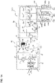
- FIG. 1 is a refrigerant circuit diagram of an air-conditioning apparatus according to Embodiment 1 of the present invention.
- An air-conditioning apparatus 300 of Embodiment 1 includes a compressor 1, a four-way valve 2, an indoor heat exchanger 3, an expansion valve 4, and an outdoor heat exchanger 8. This means that at the time of heating operation, the refrigeration cycle of the air-conditioning apparatus 300 is configured such that the compressor 1, the four-way valve 2, the indoor heat exchanger 3, the expansion valve 4, and the outdoor heat exchanger 8 are connected in this order.
- the refrigeration cycle of the air-conditioning apparatus 300 is configured such that the compressor 1, the four-way valve 2, the outdoor heat exchanger 8, the expansion valve 4, and the indoor heat exchanger 3 are connected in this order.
- the indoor heat exchanger 3 functions as a condenser at the time of heating operation, and functions as an evaporator at the time of cooling operation.
- the outdoor heat exchanger 8 functions as an evaporator at the time of heating operation, and functions as a condenser at the time of cooling operation.
- the four-way valve 2 is not particularly required.
- the outdoor heat exchanger 8 is configured of a plurality of fins 16 and a plurality of heat transfer tubes 15, as described below.
- One end portion (end portion of a refrigerant inflow side at the time of heating operation) of each heat transfer tube 15 is connected with a liquid header 7, and the other end portion (end portion of a refrigerant outflow side at the time of heating operation) of each heat transfer tube 15 is connected with a gas header 9.
- the liquid header 7 is divided into two liquid header portions 7a and 7b in an up and down direction.
- the air-conditioning apparatus 300 of Embodiment 1 includes a first gas-liquid separator 5 for separating two-phase refrigerant, having flowed out of the expansion valve 4, into gas refrigerant and liquid refrigerant at the time of heating operation, and a bypass 10 that connects the first gas-liquid separator 5 and the suction side of the compressor 1 and adjusts the quantity of the gas refrigerant, separated by the first gas-liquid separator 5, to be returned to the suction side of the compressor 1.
- the bypass 10 connects the first gas-liquid separator 5 and the suction side of the compressor 1, and is configured of a first bypass pipe 10a for returning gas refrigerant, separated by the first gas-liquid separator 5, to the suction side of the compressor 1, and a flow rate control mechanism 11 (flow rate control valve, for example) that adjust the flow rate of the gas refrigerant flowing in the first bypass pipe 10a.
- a flow rate control mechanism 11 flow rate control valve, for example
- the air-conditioning apparatus 300 of Embodiment 1 further includes a shunt 6 that connects the first gas-liquid separator 5 and lower portions, for example, of the respective liquid header portions 7a and 7b, and supplies the two-phase refrigerant, in which the quality is adjusted by the first gas-liquid separator 5, to the liquid header portions 7a and 7b, respectively.
- a shunt 6 that connects the first gas-liquid separator 5 and lower portions, for example, of the respective liquid header portions 7a and 7b, and supplies the two-phase refrigerant, in which the quality is adjusted by the first gas-liquid separator 5, to the liquid header portions 7a and 7b, respectively.
- the above-described constituent elements, constituting the air-conditioning apparatus 300, are stored in an outdoor unit 100 and an indoor unit 200.
- the compressor 1, the four-way valve 2, the expansion valve 4, the first gas-liquid separator 5, the shunt 6, the liquid header 7, the outdoor heat exchanger 8, the gas header 9, and the bypass 10 are stored.
- the indoor heat exchanger 3 is stored.
- the outdoor unit 100 is also provided with a fan 12 that supplies air (outdoor air), to which heat exchange is applied, to the outdoor heat exchanger 8. The configuration of storing the fan 12 in the outdoor unit 100 will be described below.
- the air-conditioning apparatus 300 of Embodiment 1 also includes a controller 20 configured of a microcomputer, for example.
- the controller 20 controls the rotation speed of the compressor 1, the flow channel of the four-way valve 2, the opening degree of the expansion valve 4, the opening degree of the flow rate control mechanism 11, the rotation speed (air quantity) of the fan 12, and the like.
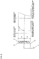
- FIG. 2 is a vertical sectional view of an outdoor unit of the air-conditioning apparatus according to Embodiment 1 of the present invention.
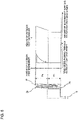
- FIG. 3 illustrates an outdoor heat exchanger of the air-conditioning apparatus according to Embodiment 1 of the present invention. It should be noted that in FIG. 2 , wind speed distribution passing through the outdoor heat exchanger 8 is also shown.
- (a) is a plan view
- (b) is a side view.
- the outdoor unit 100 according to Embodiment 1 includes an approximately rectangular parallelepiped casing 13. At least one side face of the casing 13 has an air inlet, and the outdoor heat exchanger 8 is provided to face the air inlet. It should be noted that in Embodiment 1, air inlets are formed in three side faces of the casing 13. As such, as shown in FIG. 3 , the outdoor heat exchanger 8 according to Embodiment 1 is formed in a U shape in a plan view. It should be noted that air inlets may be formed in four side faces, rather than three side faces, of the casing 13, and the outdoor heat exchanger 8 may be formed in a square shape in a plan view, for example.
- the outdoor heat exchanger 8 is configured of a plurality of fins 16 and a plurality of heat transfer tubes 15.
- the fins 16 are in a substantially rectangular shape extended in the up and down direction, and the respective fins 16 are arranged in parallel in a horizontal direction at predetermined intervals.
- the heat transfer tubes 15 are formed in a U shape in a plan view, and the respective heat transfer tubes 15 are arranged in parallel at predetermined intervals in the up and down direction so as to penetrate the fins 16. It should be noted that the heat transfer tube 15 of Embodiment 1 is formed in a U shape, and at an end portion of one side of the U shape, it is folded to be in a U shape again.
- both an end potion of the liquid header 7 (liquid header portions 7a and 7b) side and an end portion of the gas header 9 side of the heat transfer tube 15 are arranged at an end portion of one side of the U shape.
- the arrangement method may not be limited to an end portion of one side.
- the end portions of the liquid header 7 (liquid header portions 7a and 7b) side and the gas header 9 side may be arranged at end portions on both sides of the U shape.
- the outdoor unit 100 of Embodiment 1 has an air outlet formed in an upper portion of the casing 13, and the fan 12 equivalent to an outdoor fan of the present invention is provided below the air outlet.
- the outdoor unit 100 of Embodiment 1 is configured such that the air sucked into the casing 13 by the fan 12 exchanges heat with the outdoor heat exchanger 8 and then discharged from the upper portion of the casing 13. As such, as shown in FIG. 2 , as the wind speed is faster at a portion near the fan 12, the wind speed (air quantity) passing through the outdoor heat exchanger 8 increases as it comes close to the fan 12.
- the liquid header 7 has a pipe structure that is divided into two liquid header portions 7a and 7b in an up and down direction so as to extend upward and downward.
- the heat transfer tubes 15 arranged in an upper portion of the outdoor heat exchanger 8 are connected with the liquid header portion 7a, and the heat transfer tubes 15 arranged in the lower portion of the outdoor heat exchanger 8 are connected with the liquid header portion 7b.
- the outdoor heat exchanger 8 is divided into a plurality of divided regions in the up and down direction, and different liquid header portions are connected with the respective different regions.
- the shunt 6 supplies two-phase refrigerant of the amount corresponding to the air quantity of the divided regions connected with the liquid header portion 7a and 7b, with respect to the respective liquid header portion 7a and 7b. Specifically, the shunt 6 supplies the two-phase refrigerant to the respective liquid header portions 7a and 7b such that an average refrigerant flow rate of the heat transfer tubes 15 connected with the liquid header portion 7a (flow rate of two-phase refrigerant supplied to the liquid header portion 7a / the number of heat transfer tubes 15 connected with the liquid header portion 7a) becomes larger than an average refrigerant flow rate of the heat transfer tubes 15 connected with the liquid header portion 7b (flow rate of two-phase refrigerant supplied to the liquid header portion 7b / the number of heat transfer tubes 15 connected with the liquid header portion 7b).
- the shunt 6 of Embodiment 1 is formed such that the inner diameter of the flow channels connected with the liquid header portions 7a and 7b differs according to each liquid header portion. Thereby, the amount of two-phase refrigerant supplied to each of the liquid header portions 7a and 7b can be changed.
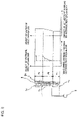
- FIG. 4 is a sectional view illustrating an example of the shunt in the air-conditioning apparatus according to Embodiment 1 of the present invention.
- the shunt 6 includes a main body 6a and connection pipes 6b of the same number as the number of liquid header portions.
- the main body 6a has a flow channel in which one end is connected with the first gas-liquid separator 5, and the other end is branched to be in the same number as the number of the liquid header portions.
- the connection pipe 6b is configured such that one end thereof is connected with another end (each branched portion) of the flow channel formed in the main body 6a, and the other end is connected with each of the liquid header portions 7a and 7b.
- the sectional area of the branched portion connected with the liquid header portion 7a is formed to be larger than the sectional area of the branched portion connected with the liquid header portion 7b, and that the sectional area of the flow channel connected with the liquid header portion 7a is formed to be larger than the sectional area of the flow channel connected with the liquid header portion 7b.
- an orifice 14 is provided to the branched portion connected with the liquid header portion 7b, and that the sectional area of the flow channel connected with the liquid header portion 7a is formed to be larger than the sectional area of the flow channel connected with the liquid header portion 7b.
- the sectional area of the connection pipe 6b connected with the liquid header portion 7a is formed to be larger than the sectional area of the connection pipe 6b connected with the liquid header portion 7b, and that the sectional area of the flow channel connected with the liquid header portion 7a is formed to be larger than the sectional area of the flow channel connected with the liquid header portion 7b.
- a larger amount of refrigerant can be supplied to the liquid header portion 7a side connected with a divided region of larger air quantity.
- the length of the connection pipe unit 6b connected with the liquid header portion 7a may be formed to be longer than the length of the connection pipe unit 6b connected with the liquid header portion 7b. Even such a configuration, a larger amount of refrigerant can be supplied to the liquid header portion 7a side connected with a divided region of a large air quantity.
- the flow dividing ratio of the refrigerant supplied to the liquid header portion 7a and the liquid header portion 7b may be fixed according to the air quantity distribution in an operating state where the air quantity distribution is biased most. Further, as shown in FIG. 8 or FIG. 9 described below, in the case where the liquid header 7 is divided into three or more, it is only necessary to increase the number of the branched portions of the flow channel formed in the main body 6a and the number of the connection pipes 6b.
- gas refrigerant compressed to be high temperature and high pressure by the compressor 1 flows into the indoor heat exchanger 3 along with the solid line of the four-way valve 2, and exchanges heat with the indoor air and discharges heat to the indoor by an air sending means such as a fan not shown, whereby the gas refrigerant is condensed to be high-temperature and high-pressure liquid refrigerant.
- the high-temperature and high-pressure liquid refrigerant is decompressed by the expansion valve 4 to be two-phase refrigerant, and flows into the first gas-liquid separator 5.
- the two-phase refrigerant is separated into gas refrigerant and liquid refrigerant.
- the flow rate thereof is controlled by the flow rate control mechanism 11, and the gas refrigerant is returned to the suction side of the compressor 1 through the bypass 10.
- the two-phase refrigerant in which the quality is controlled by bypassing the gas refrigerant in the first gas-liquid separator 5, flows into the shunt 6.
- the two-phase refrigerant in which the amount of gas refrigerant is adjusted, flows into the shunt 6.
- the two-phase refrigerant having flowed in the shunt 6 is supplied to the liquid header portion 7a and the liquid header portion 7b that are divided into two.
- the two-phase refrigerant supplied to the liquid header portion 7a is allocated to the respective heat transfer tubes 15 connected with the liquid header portion 7a (respective heat transfer tubes 15 arranged in the upper divided region in the outdoor heat exchanger 8). Further, the two-phase refrigerant supplied to the liquid header portion 7b is allocated to the respective heat transfer tubes 15 connected with the liquid header portion 7b (respective heat transfer tubes 15 arranged in the lower divided region in the outdoor heat exchanger 8).
- refrigerant is allocated to the respective heat transfer tubes 15 as shown in FIG. 5 .
- FIG. 5 illustrates distribution of refrigerant allocation in the outdoor heat exchanger of the air-conditioning apparatus according to Embodiment 1 of the present invention.
- the shunt 6 supplies, to the respective liquid header portions 7a and 7b, two-phase refrigerant of the amount corresponding to the air quantities of the divided regions connected with the liquid header portions 7a and 7b.
- a larger amount of two-phase refrigerant is supplied to the liquid header portion 7a connected with the upper divided region of the outdoor heat exchanger 8 of a larger air quantity, than that supplied to the liquid header portion 7b connected with the lower divided region of the outdoor heat exchanger 8 of a smaller air quantity.
- the outdoor heat exchanger 8 can be used efficiently.
- two-phase refrigerant in which the amount of gas refrigerant is adjusted, flows into the liquid header portions 7a and 7b.
- the refrigerant in which the gas refrigerant speed is adjusted, flows into the liquid header portions 7a and 7b.
- the liquid refrigerant in the liquid header portions 7a and 7b is lifted upward accompanied by the gas refrigerant. Accordingly, with respect to the heat transfer tube 15 of a divided region, refrigerant can be supplied along with the wind speed distribution (air quantity distribution) of the divided region. As such, the performance of the outdoor heat exchanger 8 can be further improved.
- the opening degree of the flow rate control mechanism 11 may be decreased to increase the amount of gas refrigerant flowing into the liquid header portions 7a and 7b to increase the gas refrigerant speed in the liquid header portions 7a and 7b.
- the amount of liquid refrigerant lifted upward is increased, which enables the refrigerant to be allocated according to the wind speed distribution in the divided region.
- the opening degree of the flow rate control mechanism 11 may be increased to decrease the amount of gas refrigerant flowing into the liquid header portions 7a and 7b to decrease the gas refrigerant speed in the liquid header portions 7a and 7b. Thereby, the amount of liquid refrigerant lifted upward is decreased, which enables the refrigerant to be allocated according to the wind speed distribution in the divided region.
- the two-phase refrigerant flowing into the respective heat transfer tubes 15 of the outdoor heat exchanger 8 as described above, exchanges heat with the outdoor air and absorbs heat from the outdoor and evaporates to be low-pressure gas refrigerant, passes through the four-way valve 2 and returns to the suction side of the compressor 1.
- the gas refrigerant compressed to be high temperature and high pressure by the compressor 1 flows into the outdoor heat exchanger 8 along with the broken line of the four-way valve 2.
- the refrigerant is single-phase gas, it is allocated and supplied almost equally to the refrigerant heat transfer tubes of the outdoor heat exchanger 8 by the gas header 9.
- the gas refrigerant having flowed therein, exchanges heat with the outdoor air by the fan 12 and discharges heat to the outdoor, and is condensed to high-temperature and high-pressure liquid refrigerant.
- the high-temperature and high-pressure liquid refrigerant passes through the first gas-liquid separator 5 and decompressed by the expansion valve 4 to be two-phase refrigerant, and flows into the indoor heat exchanger 3.
- the flow rate control mechanism 11 is closed to prevent the refrigerant from returning from the first gas-liquid separator 5 to the suction side of the compressor 1.
- the refrigerant exchanges heat with the indoor air and absorbs heat from the inside of the room to evaporate to become low-pressure gas refrigerant that passes through the four-way valve 2 to return to the suction side of the compressor 1.
- the air-conditioning apparatus 300 configured as Embodiment 1
- two-phase refrigerant in which the quality is adjusted by the first gas-liquid separator 5, is supplied to the shunt 6.
- the air-conditioning apparatus 300 of Embodiment 1 is able to adjust the gas refrigerant speed flowing in the respective liquid header portions 7a and 7b.
- the shunt 6 supplies, to the respective liquid header portions 7a and 7b, two-phase refrigerant of the amount corresponding to the divided regions of the outdoor heat exchanger 8 connected with the respective liquid header portions 7a and 7b.
- the air-conditioning apparatus 300 of Embodiment 1 is able to adjust the amount of liquid refrigerant lifted upward in the liquid header portion by the gas refrigerant according to the wind speed distribution, the performance of the outdoor heat exchanger 8 can be improved sufficiently.
- the liquid header portions 7a and 7b are formed to be in the same shape.
- the shapes of the liquid header portion 7a and the liquid header portion 7b may be different.
- the inner diameters of the liquid header portion 7a and the liquid header portion 7b may be different.
- FIG. 6 illustrates distribution of refrigerant allocation in an outdoor heat exchanger of an air-conditioning apparatus according to Embodiment 2 of the present invention.
- the distribution of the wind speed in the upper divided region is more biased compared with the distribution of the wind speed in the lower divided region. It should be noted that in the outdoor heat exchanger 8 of Embodiment 2, the distribution of the wind speed is constant in the lower divided region.
- an inner diameter D7a of the liquid header portion 7a is formed to be smaller than an inner diameter D7b of the liquid header portion 7b.
- the liquid refrigerant in the liquid header portion 7a is lifted upward accompanied by the gas refrigerant.
- the refrigerant can be supplied to the heat transfer tubes 15 of the divided region along the distribution of the wind speed (distribution of air quantity) of the divided region.
- the capacity of a portion of the outdoor heat exchanger 8 connected with the liquid header portion 7a arranged at a position close to the fan 12 is smaller.
- a refrigerant flow rate G7a flowing in the liquid header portion 7a arranged at a position closer to the fan 12 is less than a refrigerant flow rate G7b flowing in the liquid header portion 7b.
- Ha:Hb G7a:G7b is satisfied, in proportion to the heights of the liquid header portions 7a and 7b.
- the inner diameter of the liquid header portion 7a at a position close to the fan 12 is D7a', which is smaller than the inner diameter D7b of the liquid header portion 7b at a position far from the fan 12.
- Embodiment 2 is not simply the size of the inner diameters of the liquid header portions 7a and 7b, but setting the inner diameter D7a of the liquid header portion 7a at a position close to the fan 12 to satisfy D7a ⁇ D7a', considering a diameter equivalent to the refrigerant mass flux. This also applies to the case of Ha > Hb.
- the liquid header portion 7a corresponds to a first liquid header portion of the present invention.
- the liquid header portion 7b corresponds to a second liquid header portion of the present invention.
- D7a' corresponds to D1 of the present invention, and D7a corresponds to D of the present invention.
- Embodiment 2 by forming the inner diameter of the liquid header portion 7a arranged at a position close to the fan 12 (connected with a divided region where distribution of the wind speed is more biased) to be smaller than the inner diameter of the liquid header portion 7b arranged at a position away from the fan 12 (connected with a divided region where distribution of the wind speed is less biased) as in Embodiment 2, it is possible to realize refrigerant allocation along the distribution of the wind speed more, and to further improve the capability of the outdoor heat exchanger 8.
- the heights of the liquid header portion 7a and the liquid header portion 7b may be different. It should be noted that the configurations not described in Embodiment 3 are the same as those of Embodiment 1 or Embodiment 2, and the configurations that are same as those of the above-described embodiments are denoted by the same reference numerals.
- FIG. 7 illustrates distribution of refrigerant allocation in an outdoor heat exchanger of an air-conditioning apparatus according to Embodiment 3 of the present invention.
- the width in the up and down direction of the upper divided region, where the distribution of the wind speed distribution is more biased is larger than the width in the up and down direction of the lower divided region where the distribution of the wind speed is less biased (constant in FIG. 7 ).
- the liquid header 7 is divided into two liquid header portions 7a and 7b.
- the number of divisions of the liquid header 7 is not limited to two. It is obvious that the liquid header 7 may be divided into three or more as in the case of Embodiment 4. It should be noted that the configurations not described in Embodiment 4 are the same as those in any of Embodiments 1 to 3, and the configurations that are same as those of the above-described embodiments are denoted by the same reference numerals.
- FIG. 8 illustrates distribution of refrigerant allocation in an outdoor heat exchanger of an air-conditioning apparatus according to Embodiment 4 of the present invention.
- the liquid header 7 is divided into three, namely a liquid header portion 7a arranged in an upper portion, a liquid header portion 7b arranged in an intermediate portion, and a liquid header portion 7c arranged in a lower portion. Then, the inner diameter of the liquid header portion 7a connected with the upper divided region, where the distribution of the wind speed is most biased, is formed to be the smallest, the inner diameter of the liquid header portion 7b connected with the intermediate divided region, where the distribution of the wind speed is secondly biased, is formed to be the second smallest, and the inner diameter of the liquid header portion 7c connected with the lower divided region, where the distribution of the wind speed is least biased (constant), is formed to be the largest.
- Embodiments 2 to 4 as the distribution of the wind speed is most biased in the upper divided region of the outdoor heat exchanger 8, the inner diameter of the liquid header portion 7a arranged in an upper portion (that is, arranged at a position closest to the fan 12) is formed to be the smallest.
- the liquid header 7 may be configured as described below. It should be noted that the configurations not described in Embodiment 5 are the same as those in any of Embodiments 1 to 4, and the configurations that are the same as those of the above-described embodiments are denoted by the same reference numerals.
- FIG. 9 illustrates distribution of refrigerant allocation in an outdoor heat exchanger of an air-conditioning apparatus according to Embodiment 5 of the present invention.
- the outdoor heat exchanger 8 is configured such that an outdoor heat exchanger 8a is added to a part thereof and the number of columns of the heat exchangers is increased.
- an outdoor heat exchanger 8a is added to a part thereof and the number of columns of the heat exchangers is increased.
- distribution of the wind speed is leveled.
- distribution of the wind speed is less biased (constant) in the upper and lower divided regions of the outdoor heat exchanger 8, and distribution of the wind speed is more biased in the central divided region of the outdoor heat exchanger 8.
- the liquid header 7 is divided into three, namely the liquid header portion 7a arranged in the upper portion, the liquid header portion 7b arranged in the intermediate portion, and the liquid header portion 7c arranged in the lower portion. Then, the inner diameter of the liquid header portion 7b connected with the central divided region, where distribution of the wind speed is more biased, is formed to be smaller, and the inner diameters of the liquid header portions 7a and 7c connected with the upper and lower divided regions, where distribution of the wind speed is less biased (constant), are formed to be larger.
- the inner diameter of the liquid header portion 7b By forming the inner diameter of the liquid header portion 7b to be smaller than the inner diameters of the liquid header portions 7a and 7c, it is possible to supply refrigerant that is uniform in the height direction of the outdoor heat exchanger 8 to a portion where distribution of the air quantity is constant, and to supply refrigerant to a portion where distribution of the wind speed is increased along the distribution of the wind speed of the outdoor heat exchanger 8. As such, performance of the outdoor heat exchanger 8 can be improved sufficiently.
- FIG. 9 shows the case where the number of columns of the heat exchangers is increased, besides this, distribution of the wind speed is leveled at such a position by reducing the fin pitch of the outdoor heat exchanger 8, increasing the arrangement density of the heat transfer tubes 15 of the outdoor heat exchanger 8, or the like.
- the present invention is also applicable to a multi-split type air-conditioning apparatus in which a plurality of indoor units are connected with a heat source unit (outdoor unit), and cooling or heating can be performed selectively by each indoor unit in such a manner that cooling can be performed in one indoor unit while heating can be performed in another indoor unit simultaneously.
- a heat source unit outdoor unit
- cooling or heating can be performed selectively by each indoor unit in such a manner that cooling can be performed in one indoor unit while heating can be performed in another indoor unit simultaneously.
- An air-conditioning apparatus (multi-split type air-conditioning apparatus) according to Embodiment 6 includes the outdoor unit having at least the compressor, a four-way valve, the liquid header divided into the liquid header portions in the up and down direction, the shunt, the outdoor heat exchanger, and the outdoor fan; a relay unit connected with the outdoor unit by a first connection pipe and a second connection pipe; and a plurality of indoor units each having at least an indoor heat exchanger and connected with the relay unit in parallel with each other.
- the outdoor unit includes a first path for guiding refrigerant, discharged from the compressor, to the second connection pipe through the four-way valve, the liquid header, and the outdoor heat exchanger; and a second path for guiding the refrigerant to the second connection pipe through the four-way valve while bypassing the liquid header and the outdoor heat exchanger, according respective operation modes of cooling, heating, cooling main, and heating main.
- the relay unit includes a second gas-liquid separator connected to the middle of the second connection pipe; a switching unit that selectively connects each of the indoor units and either the first connection pipe or the second connection pipe; a second bypass pipe connecting the second gas-liquid separator and each of other indoor units; a third bypass pipe connecting the first connection pipe and the second bypass pipe; and a bypass pipe flow rate control device interposed in the third bypass pipe and functioning as the expansion valve.
- the air conditioning apparatus further includes a third gas-liquid separator connected with the first connection pipe and functioning as the first gas-liquid separator in the heating operation mode and the heating main operation mode; a gas side outlet pipe and a flow rate control mechanism connecting the third gas-liquid separator and the suction side of the compressor, and functioning as the bypass in the heating operation mode and the heating main operation mode; and a third path for supplying two-phase refrigerant, in which quality is adjusted by the third gas-liquid separator, to the shunt, in the heating operation mode and the heating main operation mode.
- the indoor unit includes an indoor heat exchanger functioning as the condenser when the indoor unit performs heating, and a first flow rate control device functioning as the expansion valve.
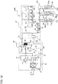
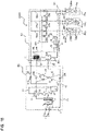
- FIG. 10 is a refrigerant circuit diagram illustrating an example of a refrigerant circuit configuration of a multi-split type air-conditioning apparatus 10000 according to Embodiment 6 of the present invention. Based on FIG. 10 , a refrigerant circuit configuration of the multi-split type air-conditioning apparatus 10000 will be described.
- the multi-split type air-conditioning apparatus 10000 according to Embodiment 6 includes an outdoor unit (also referred to as a heat source unit) 101, a relay unit 102, and a plurality of indoor units 103 (103a, 103b, and 103c). It should be noted that while description is given on the case where one outdoor unit is connected with one relay unit and three indoor units in this embodiment, the case of connecting two or more outdoor units, two or more relay units, and two or more indoor units is the same.
- the outdoor unit 101 includes therein a compressor 1 that compresses and discharges refrigerant, a four-way valve 2 that is a switching valve for switching the refrigerant flow direction in the outdoor unit 101, a gas header 9, an outdoor heat exchanger 8, a liquid header 7 (liquid header portions 7a and 7b), a shunt 6, an accumulator 44, and a third gas-liquid separator 140.
- the inlet of the third gas-liquid separator 140 is connected with a first connection pipe 21 provided inside a relay unit 102 described below.
- a liquid side outlet pipe 25 for discharging liquid refrigerant in which gas and liquid are separated by the third gas-liquid separator 140, or two-phase refrigerant in which the quality is adjusted, is connected with the four-way valve via a check valve 160.
- the check valve 160 allows liquid refrigerant to flow only from the third gas-liquid separator 140 to the four-way valve 2. Further, a gas side outlet pipe 26 for discharging gas refrigerant in which gas and liquid are separated by the third gas-liquid separator 140, is connected with the inlet or the inside of the accumulator 44 via a gas side bypass flow channel resistance 150 functioning as a flow rate control mechanism. In this way, it is configured that the refrigerant in the third gas-liquid separator 140 flows in one direction to the suction side of the compressor 1.
- the compressor 1, the four-way valve 2, the gas header 9, the outdoor heat exchanger 8, (the liquid header portions 7a and 7b), and the shunt 6 are connected in this order by the discharge pipe 31. Further, the outdoor heat exchanger 8 is connected with the relay unit 102 via the second connection pipe 22 narrower than the first connection pipe 21, by the refrigerant pipe 32 in which the check valve 190 is provided.
- the check valve 190 has a function of allowing refrigerant to flow only from the outdoor heat exchanger 8 to the second connection pipe 22.
- the liquid side outlet pipe 25 and the refrigerant pipe 32 are connected with each other by a short-circuit pipe 33 having a check valve 170 and a short-circuit pipe 34 having a check valve 180. Both the check valve 170 and the check valve 180 allow refrigerant to flow only from the liquid side outlet pipe 25 to the refrigerant pipe 32.
- the circuits having the check valves 160, 170, 180, and 190 constitute a flow channel switching circuit 35 on the outdoor unit side.
- the outlet of the accumulator 44 and the suction port of the compressor 1 are connected with each other by a suction pipe 36, and the four-way valve 2 and the accumulator 44 are connected with each other by a refrigerant pipe 37.
- the outdoor unit 101 is provided with a fan 12 (not shown in FIG. 10 , see FIG. 2 ) that supplies air (outdoor air) on which heat exchange is to be performed, to the outdoor heat exchanger 8.
- a fan 12 (not shown in FIG. 10 , see FIG. 2 ) that supplies air (outdoor air) on which heat exchange is to be performed, to the outdoor heat exchanger 8.
- the outdoor unit 101 and the relay unit 102 are connected with each other by the first connection pipe 21 that is a wide pipe, and the second connection pipe 22 that is a pipe narrower than the first connection pipe 21.
- the relay unit 102 includes a second gas-liquid separation device (intra-relay unit gas-liquid separation device) 50 connected to the middle of the second connection pipe 22.
- a gas phase portion of the second gas-liquid separator 50 is connected with branch pipes 21a, 21b, and 21c of the indoor units 103a, 103b, and 103c connected parallel to each other, via solenoid valves 120a, 120b, and 120c, respectively.
- the branch pipes 21a, 21b, and 21c are connected with indoor heat exchangers 1000a, 1000b, and 1000c of the indoor units 103a, 103b, and 103c. Further, the branch pipes 21a, 21b, and 21c are provided with the solenoid valves 130a, 130b, and 130c.
- a circuit configured of the solenoid valves 120a, 120b, 120c and solenoid valves 130a, 130b, and 130c is called a switching unit 104.
- liquid phase portion of the second gas-liquid separator 50 is connected with a second bypass pipe 23, and the second bypass pipe 23 is connected with the indoor units 103a, 103b, and 103c via branch pipes 22a, 22b, and 22c, respectively.
- the branch pipes 22a, 22b, and 22c are provided with first flow rate control devices 110a, 110b, and 110c.
- a third bypass pipe 24 branching from the first connection pipe 21 is provided, and the other end of the third bypass pipe 24 is connected with the second bypass pipe 23.
- a first heat exchanger 60 and a second heat exchanger 70 are provided between the second bypass pipe 23 and the third bypass pipe 24, for exchanging heat between refrigerant flowing in the second bypass pipe 23 and refrigerant flowing in the third bypass pipe 24, are provided.
- the second bypass pipe 23, located between the first heat exchanger 60 and second heat exchanger 70, is provided with an openable/closable third flow rate control device 85. Further, between the second heat exchanger 70 and the other end connecting portion of the third bypass pipe 24 (connecting portion with the second bypass pipe 23), an openable/closable second flow rate control device 90 (bypass pipe flow rate control device) is provided.
- the indoor units 103a, 103b, and 103c are connected with each other to allow refrigerant to circulate through the branch pipes 21a, 21b, and 21c branching from the first connection pipe 21 of the relay unit 102 and the branch pipes 22a, 22b, and 22c branching from the second bypass pipe 23.
- the respective indoor units 103a, 103b, and 103c include indoor heat exchangers 1000a, 1000b, and 1000c, and the openable/closable first flow rate control devices 110a, 110b, and 110c, respectively.
- the first flow rate control devices 110a, 110b, and 110c are connected in the vicinity of the indoor heat exchangers 1000a, 1000b, and 1000c, and at the time of cooling, they are controlled according to the degree of superheat of the outlet side of the indoor heat exchangers 1000a, 1000b, and 1000c, and at the time of heating, they are controlled according to the degree of subcooling.
- Operational actions at the time of various types of operation performed by the multi-split type air-conditioning apparatus 10000 will be described.
- Operational actions by the multi-split type air-conditioning apparatus 10000 include four operation modes, namely cooling, heating, cooling main, and heating main.
- a cooling operation mode is an operation mode in which all operating indoor units perform cooling
- a heating operation mode is an operation mode in which all operating indoor units perform heating.
- a cooling main operation mode is an operation mode in which an indoor unit performing cooling operation and an indoor unit performing heating operation are mixed, and the cooling load is larger than the heating load.
- a heating main operation mode is an operation mode in which an indoor unit performing cooling operation and an indoor unit performing heating operation are mixed, and the heating load is larger than the cooling load.
- the outdoor heat exchanger 8 is connected to the discharge side of the compressor 1, and acts as a condenser (radiator).
- the outdoor heat exchanger 8 is connected to the suction side of the compressor 1, and acts as an evaporator.
- the flow of refrigerant in each operation mode will be described.
- FIG. 11 is a refrigerant circuit diagram illustrating a flow of refrigerant at the time of heating operation in the multi-split type air-conditioning apparatus of Embodiment 6.
- description will be given on the case where all of the indoor units 103a, 103b, and 103c attempt to perform heating.
- the four-way valve 2 is switched such that the refrigerant discharged from the compressor 1 passes through the second connection pipe 22 to flow into the switching unit 104 configured of the solenoid valves 120a, 120b, and 120c and the solenoid valves 130a, 130b, and 130c, without bypassing through the outdoor heat exchanger 8 and the liquid header 7.
- the solenoid valves 130a, 130b, and 130c provided to the branch pipes 21a, 21b, and 21c are controlled to be in a closed state
- the solenoid valves 120a, 120b, and 120c provided to the pipes connected from the second connection pipe 22 to the indoor units 103a, 103b, and 103c are controlled to be in an open state.
- the pipes and devices shown by the solid lines indicate paths through which the refrigerant circulates, and the paths indicated by the dotted lines indicate that the refrigerant does not flow therethrough.
- the refrigerant in the low-temperature and low-pressure two-phase gas-liquid state having flowed out of the second flow rate control device 90, flows into the third gas-liquid separator 140 in the outdoor unit 101 via the third bypass pipe 24 and the first connection pipe 21.
- the gas refrigerant, in which gas and liquid are separated by the third gas-liquid separator 140 flows into the inlet or the inside of the accumulator 44 via the gas side outlet pipe 26 and the gas side bypass flow channel resistance 150.
- the two-phase refrigerant in which gas and liquid are separated and the quality is controlled by the third gas-liquid separator 140, flows from the liquid side outlet pipe 25 through the short circuit pipe 33 and the check valve 170, and then flows into the shunt 6.
- the two-phase refrigerant, flowing in the shunt 6, is supplied to the liquid header portion 7a and the liquid header portion 7b that are divided into two.
- the two-phase refrigerant, supplied to the liquid header portion 7a is allocated to the respective heat transfer tubes 15 connected with the liquid header portion 7a (respective heat transfer tubes 15 arranged in the upper divided region of the outdoor heat exchanger 8). Further, the two-phase refrigerant, supplied to the liquid header portion 7b, is allocated to the respective heat transfer tubes 15 connected with the liquid header portion 7b (respective heat transfer tubes 15 arranged in the lower divided portion of the outdoor heat exchanger 8).
- the refrigerant flowing in the outdoor heat exchanger 8 is heated, while cooling the outdoor air, to be low-temperature and low-pressure gas refrigerant.
- the low-temperature and low-pressure gas refrigerant having flowed out of the outdoor heat exchanger 8, passes through the four-way valve 2 via the gas header 9, and joins the gas refrigerant, in which gas and liquid are separated by the third gas-liquid separator 140, at the inlet or the inside of the accumulator 44, and flows into the compressor 1 and is compressed. Afterwards, the refrigerant circulates the same path as described above.
- FIG. 12 is a refrigerant circuit diagram illustrating a flow of refrigerant at the time of cooling operation in the multi-split type air-conditioning apparatus according to Embodiment 6 of the present invention.
- description will be given on the case where all of the indoor units 103a, 103b, and 103c attempt to perform cooling.
- the four-way valve 2 is switched such that the refrigerant, discharged from the compressor 1, flows into the outdoor heat exchanger 8.
- the solenoid valves 130a, 130b, and 130c connected with the indoor units 103a, 103b, and 103c are controlled to be in an open state
- the solenoid valves 120a, 120b, and 120c are controlled to be in a closed state.
- the pipes and devices shown by the solid lines indicate paths in which the refrigerant circulates, and the paths shown by the dotted lines indicate that refrigerant does not flow therethrough.
- the high-temperature and high-pressure gas refrigerant discharged from the compressor 1, flows into the outdoor heat exchanger 8 via the four-way valve 2. At this time, the refrigerant is cooled, while heating the outdoor air, to be medium-temperature and high-pressure liquid refrigerant.
- the liquid refrigerant cooled by the first heat exchanger 60 and the second heat exchanger 70 flows into the second branch portion 105 configured of the branch pipes 22a, 22b, and 22c, while allowing a part of the refrigerant to bypass to flow into the third bypass pipe 24.
- the high-pressure liquid refrigerant flowing in the second branch portion 105 branches at the second branch portion 105 and the respective portions of the refrigerant flow into the first flow rate control devices 110a, 110b, and 110c. Then, the high-pressure liquid refrigerant is throttled by the first flow rate control devices 110a, 110b, and 110c to be expanded and compressed to be in a low-temperature and low-pressure two-phase gas-liquid state.
- the gas refrigerant passing through the first connection pipe 21 flows into the third gas-liquid separator 140, and flows out while branching to the two paths, namely the gas side outlet pipe 26 and the liquid side outlet pipe 25.
- the gas refrigerant, flowing to the gas side outlet pipe 26, passes through the gas side bypass flow channel resistance 150 and flows into the inlet or the inside of the accumulator 44.
- the gas refrigerant, flowing to the liquid side outlet pipe 25, passes through the check valve 160 and flows into the accumulator 44 via the four-way valve 2.
- FIG. 13 is a refrigerant circuit diagram illustrating a flow of refrigerant at the time of heating main operation in the multi-split type air-conditioning apparatus according to Embodiment 6 of the present invention.
- the indoor unit 103c performs cooling and the indoor units 103a and 103b perform heating.
- the four-way valve 2 is switched such that the refrigerant discharged from the compressor 1 passes through the second connection pipe 22 and flows into the switching unit 104 configured of the solenoid valves 120a, 120b, and 120c and the solenoid valves 130a, 130b, and 130c.
- the solenoid valves 130a, 130b, and 120c connected with the indoor units 103a, 103b, and 103c are controlled to be in a closed state, and the solenoid valves 120a, 120b, and 130c are controlled to be in an open state.
- the pipes and the devices shown by the solid lines indicate paths in which refrigerant flows, and the paths shown by the dotted lines indicate that refrigerant does not flow therethrough.
- the refrigerant in the low-temperature and low-pressure two-phase gas-liquid state having flowed out of the first flow rate control device 110c, flows into the indoor heat exchanger 1000c. Then, the refrigerant is heated, while cooling the indoor air, to be low-temperature and low-pressure gas refrigerant.
- the residual of the high-pressure liquid refrigerant flowing from the indoor heat exchangers 1000a and 1000b, performing heating, to the second branch portion 105 flows into the second flow rate control device 90.
- the high-pressure liquid refrigerant is throttled by the second flow rate control device 90 to be expanded (decompressed) to be in a low-temperature and low-pressure two-phase gas-liquid.
- the refrigerant in the low-temperature and low-pressure two-phase gas-liquid state, having flowed out of the second flow rate control device 90 passes through the third bypass pipe 24 and flows into the first connection pipe 21, and joins the refrigerant in a low-temperature and low-pressure vapor state having flowing from the indoor heat exchanger 1000c that performs cooling.
- the two-phase refrigerant, in which gas and liquid are separated and the quality is controlled by the third gas-liquid separator 140 flows from the liquid side outlet pipe 25 through the short circuit pipe 33 and the check valve 170, into the shunt 6.
- the two-phase refrigerant flowing in the shunt 6 is supplied to the liquid header portion 7a and the liquid header portion 7b that are divided into two. Then, the two-phase liquid refrigerant, supplied to the liquid header portion 7a, is allocated to the respective heat transfer tubes 15 connected with the liquid header portion 7a (respective heat transfer tubes 15 arranged in the upper divided region of the outdoor heat exchanger 8).
- the two-phase refrigerant, supplied to the liquid header portion 7b, is allocated to the respective heat transfer tubes 15 connected with the liquid header portion 7b (respective heat transfer tubes 15 arranged in the lower divided portion of the outdoor heat exchanger 8).
- the refrigerant having flowed into the outdoor heat exchanger 8 absorbs heat from the outdoor air and is heated, while cooling the outdoor air, to be low-temperature and low-pressure gas refrigerant.
- the low-temperature and low-pressure gas refrigerant having flowed out of the outdoor heat exchanger 8, passes through the four-way valve 2, joins the gas refrigerant, in which gas and liquid are separated by the third gas-liquid separator 140, at the inlet or the inside of the accumulator 44, and the refrigerant flows into the compressor 1 and is compressed. At this time, by allowing a part of gas refrigerant to bypass by the third gas-liquid separator 140, it is possible to reduce a pressure loss of the outdoor heat exchanger 8.
- FIG. 14 is a refrigerant circuit diagram illustrating a flow of refrigerant at the time of cooling main operation in the multi-split type air-conditioning apparatus according to Embodiment 6 of the present invention.
- the indoor units 103b and 103c perform cooling and the indoor unit 103a performs heating.
- the four-way valve 2 is switched such that the refrigerant, discharged from the compressor 1, flows into the outdoor heat exchanger 8.
- the solenoid valves 120a, 130b, and 130c connected with the indoor units 103a, 103b, and 103c are controlled to be in an open state, and the solenoid valves 130a, 120b, and 120c are controlled to be in a closed state.
- the pipes and the devices shown by the solid lines indicate paths in which refrigerant flows, and the paths shown by the dotted lines indicate that refrigerant does not flow therethrough.
- the high-temperature and high-pressure gas refrigerant discharged from the compressor 1 flows into the outdoor heat exchanger 8 via the four-way valve 2. At this time, in the outdoor heat exchanger 8, the refrigerant is cooled while heating the outdoor air, remaining the amount of heat required for heating, to be in a medium-temperature and high-pressure two-phase gas-liquid state.
- the liquid refrigerant, separated by the second gas-liquid separator 50 flows into the first heat exchanger 60, and exchanges heat with the low-pressure refrigerant flowing in the third bypass pipe 24 to be cooled.
- the refrigerant having flowed out of the indoor heat exchanger 1000a that performs heating and the refrigerant having flowed out of the first heat exchanger 60 pass through the first flow rate control device 110a and the third flow rate control device 85, and the second heat exchanger 70, respectively, and join.
- the joined liquid refrigerant branches at the second branch portion 105 configured of the branch pipes 22a, 22b, and 22c, while allowing a portion of the refrigerant to bypass to flow into the third bypass pipe 24, and the respective portions of the refrigerant flow into the first flow rate control devices 110b and 110c of the indoor units 103b and 103c that perform cooling. Then, the high-pressure liquid refrigerant is throttled by the first flow rate control devices 110b and 110c and expanded and decompressed to be in a low-temperature and low-pressure two-phase gas-liquid state. Changes in the state of the respective portions of the refrigerant by the first flow rate control devices 110b and 110c are performed under a condition that enthalpy is constant.
- the sectional area of the flow channel from the third gas-liquid separator 140 to the accumulator 44 is increased, whereby it is possible to reduce a pressure loss in the path.
- the compressor suction temperature is maintained at a high level, and the performance of the compressor 1 is improved.
- the shunt 6 supplies, to the respective liquid header portions 7a and 7b, two-phase refrigerant of the amount corresponding to the divided regions of the outdoor heat exchanger 8 to which the respective liquid header portions 7a and 7b are connected.
- the amount of liquid refrigerant lifted upward by the gas refrigerant in the liquid header portion can be adjusted according to the distribution of the wind speed, and the refrigerant can be supplied to the divided region along the distribution of the wind speed. As such, performance of the outdoor heat exchanger 8 can be improved sufficiently.
- Embodiment 6 describes an example using the outdoor heat exchanger 8 and the liquid header 7 shown in Embodiment 1, the outdoor heat exchanger 8 and the liquid header 7 described in Embodiments 2 to 5 may be used. The effects described in Embodiments 2 to 5 can be achieved.
- first heat exchanger 60, the second heat exchanger 70, and the third flow rate control device 85, provided to the second bypass pipe 23, are used for increasing the degree of subcooling of the liquid refrigerant flowing out of the second gas-liquid separator 50.
- the first heat exchanger 60, the second heat exchanger 70, and the third flow rate control device 85 are not indispensable configurations in the present invention.
- the multi-split type air-conditioning apparatus 10000 in which the present invention can be implemented, is not limited to the multi-split type air-conditioning apparatus 10000 described in Embodiment 6. It may be configured as described below. It should be noted that the configurations not described in Embodiment 7 are the same as those in any of Embodiments 1 to 6, and the configurations that are the same as those of the above-described embodiments are denoted by the same reference numerals.
- the relay unit includes a plurality of intermediate heat exchangers functioning as the condensers when the indoor units perform heating, and a plurality of first flow rate control devices connected with the respective intermediate heat exchangers and functioning as the expansion valves.
- the indoor unit includes an indoor heat exchanger connected with the intermediate heat exchanger.
- a closed first refrigerant circuit is configured, and to allow refrigerant other than the above-described refrigerant to flow in the indoor unit and the intermediate heat exchanger of the relay unit, a closed second refrigerant circuit is configured.
- FIG. 15 is a refrigerant circuit diagram illustrating an example of a refrigerant circuit of the multi-split type air-conditioning apparatus according to Embodiment 7 of the present invention. States of the four-way valve 2 and the solenoid valves 120a, 120b, 120c, 130a, 130b, and 130c in the respective operation modes will be described below.
- FIG. 15 shows the orientation of the four-way valve 2 at the time of cooling operation.
- the solenoid valves 120a, 120b, and 120c in the relay unit 102 are controlled to be in a closed state, and the solenoid valves 130a, 130b, and 130c are controlled to be in an open state.
- the four-way valve 2 is switched such that the refrigerant flows from the compressor 1 to the indoor unit 103, and the solenoid valves 120a, 120b, and 120c in the relay unit 102 are controlled to be in an open state, and the solenoid valves 130a, 130b, and 130c are controlled to be in a closed state.
- the four-way valve 2 is switched such that the refrigerant flows from the compressor 1 to the outdoor heat exchanger 8, the solenoid valves 130a, 130b, and 120c in the relay unit 102 are controlled to be in an open state, and the solenoid valves 120a, 120b, and 130c are controlled to be in a closed state.
- the four-way valve 2 is switched such that the refrigerant flows from the compressor 1 to the indoor unit 103, the solenoid valves 120a, 120b, and 130c in the relay unit 102 are controlled to be in an open state, and the solenoid valves 130a, 130b, and 120c are controlled to be in a closed state.
- a relay unit side refrigerant circuit 41 (41a, 41b, and 41c) and an indoor unit side refrigerant circuit 42 (42a, 42b, and 42c), in which different kinds of refrigerants circulate as described below, are configured, and an intermediate heat exchanger 40 (40a, 40b, and 40c) is interposed between the two refrigerant circuits 41 and 42.
- branch pipes 22a, 22b, and 22c and the branch pipes 21a, 21b, and 21c are connected with each other such that the refrigerant circulates the outdoor unit 101 and the intermediate heat exchanger 40 (40a, 40b, and 40c) of the relay unit 102 connected with the outdoor unit 101 by the first connection pipe 21 and the second connection pipe 22, to form the closed refrigerant circuits 41a, 41b, and 41c. Then, the refrigerant circuits 41a, 41b, and 41c are provided with first flow rate control devices 110a, 110b, and 110c, respectively.
- the refrigerant circuits 42a, 42b, and 42c are configured to be closed such that refrigerant (water or antifreeze, for example) other than the above-described refrigerant circulates the indoor heat exchangers 1000a, 1000b, and 1000c of the indoor units 103a, 103b, and 103c and the intermediate heat exchangers 40 (40a, 40b, and 40c) of the relay unit 102.
- refrigerant water or antifreeze, for example
- the refrigerant circuits 42a, 42b, and 42c are provided with pumps 43a, 43b, and 43c, and the intermediate heat exchangers 40a, 40b, and 40c are interposed between the relay unit side refrigerant circuits 41a, 41b, and 41c and the indoor unit side refrigerant circuits 42a, 42b, and 42c, to allow the refrigerant flowing in the refrigerant circuit 41 and the refrigerant flowing in the refrigerant circuit 42 to exchange heat with each other by the intermediate heat exchanger 40.
- the other functions and configurations are the same as those of Embodiment 6.
- the third gas-liquid separator 140 is provided to the outdoor unit 101.
- the third gas-liquid separator 140 may be provided to the relay unit 102.
- an example in which the installment position of the third gas-liquid separator 140 is changed in the multi-split type air-conditioning apparatus 10000 shown in Embodiment 6 will be given.
- FIG. 16 is a refrigerant circuit diagram illustrating an example of a refrigerant circuit configuration of a multi-split type air-conditioning apparatus according to Embodiment 8 of the present invention.
- the third gas-liquid separator 140 is connected to the middle of the first connection pipe 21, and the third gas-liquid separator 140 is installed in the relay unit 102.
- the third gas-liquid separator 140 By installing the third gas-liquid separator 140 in the relay unit 102 in this way, as gas refrigerant or liquid refrigerant, in which gas and liquid are separated, flows in the first connection pipe 21, it is possible to significantly reduce a pressure loss caused by the extension pipe between the outdoor unit 101 and the relay unit 102.
- the other functions and configurations are the same as those of Embodiment 6 and Embodiment 7.
- gas refrigerant in which gas and liquid are separated is allowed to bypass as gas refrigerant by the third gas-liquid separator 140, and liquid refrigerant, in which gas and liquid are separated, flows out as a zeotropic refrigerant mixture in which composition ratio is biased to refrigerant having a high boiling point with the inlet of the third gas-liquid separator 140.
- zeotropic refrigerant mixture for example, R404A, R407C, or the like
- single refrigerant for example, R22 or the like
- azeotropic refrigerant mixture for example, R502, R507A, or the like
- Embodiments 1 to 9 details of a connection configuration between the liquid header portion and the outdoor heat exchanger 8 (in more detail, heat transfer tube 15) are not described particularly.
- the configurations not described in Embodiment 10 are the same as those in any of Embodiments 1 to 9, and the configurations that are the same as those of the above-described embodiments are denoted by the same reference numerals.
- FIG. 17 illustrates an outdoor heat exchanger of an air-conditioning apparatus according to Embodiment 10 of the present invention. It should be noted that in FIG. 17 , distribution of the wind speed passing through the outdoor heat exchanger 8 and the amount of refrigerant (refrigerant distribution) supplied to the outdoor heat exchanger 8 are also shown.
- respective liquid header portions 7a and 7b and the heat transfer tubes 15 of the outdoor heat exchanger 8 are connected by a plurality of branch pipes 45.
- the liquid header portion 7a arranged in an upper portion (connected with the heat transfer tubes 15 of a divided region having larger distribution of wind speed) is connected with the heat transfer tubes 15 of the outdoor heat exchanger 8 by the branch pipes 45a.
- the liquid header portion 7b arranged in a lower portion (connected with the heat transfer tubes 15 of a divided region having a smaller distribution of wind speed) is connected with the heat transfer tubes 15 of the outdoor heat exchanger 8 by the branch pipes 45b.
- the liquid header portion 7a arranged in the upper portion has a configuration in which a larger number of branch pipes 45 are connected to a region of the same area.
- the number of the branch pipes 45a is larger than the number of the branch pipes 45b.
- the gas header 9 connected to a position which is a refrigerant outflow side of the outdoor heat exchanger 8 is divided into a plurality of gas header portions in the up and down direction.
- the gas header 9 is divided into two gas header portions 9a and 9b in the up and down direction. Further, the gas header portions 9a and 9b are connected with the four-way valve 2 by a refrigerant outlet pipe 46.
- the gas header portion 9a is connected with the four-way valve 2 by a refrigerant outlet pipe 46a.
- the gas header portion 9b is connected with the four-way valve 2 by a refrigerant outlet pipe 46b.
- the refrigerant outlet pipe 46 (refrigerant outlet pipes 46a and 46b) connects the gas header 9 (gas header portions 9a and 9b) and the suction side of the compressor 1, when the outdoor heat exchanger 8 functions as an evaporator.
- the liquid header portion 7a arranged in the upper portion has a configuration in which a larger number of branch pipes 45 are connected to a region of the same area.
- the flow resistance of the refrigerant, flowing into the heat transfer tube 15 of a divided region having larger distribution of the wind speed is smaller. Accordingly, a larger amount of refrigerant can be supplied to a divided region having larger wind speed distribution.
- largely biased wind speed distribution can be managed.
- Embodiments 1 to 10 by configuring the gas header 9 as described below, it is possible to supply a larger amount of refrigerant to a divided region having larger wind speed distribution. It should be noted that the configurations not described in Embodiment 11 are the same as those in any of Embodiments 1 to 10, and the configurations that are the same as those of the above-described embodiments are denoted by the same reference numerals.
- FIG. 18 illustrates an outdoor heat exchanger of an air-conditioning apparatus according to Embodiment 11 of the present invention. It should be noted that FIG. 18 also illustrates distribution of the wind speed passing through the outdoor heat exchanger 8 and the amount of refrigerant (refrigerant distribution) supplied to the outdoor heat exchanger 8.
- the gas header 9 is divided into a plurality of gas header portions in the up and down direction.
- the gas header 9 is divided into two gas header portions 9a and 9b in the up and down direction.
- the inner diameter of the gas header portion 9a arranged in an upper portion is larger than the inner diameter of the gas header portion 9b arranged in a lower portion (connected with the heat transfer tubes 15 of a divided region of smaller wind speed distribution).
- Embodiments 1 to 11 even by configuring the gas header 9 as described below, it is possible to supply a larger amount of refrigerant to a divided region having larger wind speed distribution. It should be noted that the configurations not described in Embodiment 12 are the same as those in any of Embodiments 1 to 11, and the configurations that are the same as those of the above-described embodiments are denoted by the same reference numerals.
- FIG. 19 illustrates an outdoor heat exchanger of an air-conditioning apparatus according to Embodiment 12 of the present invention. It should be noted that in FIG. 19 , distribution of the wind speed passing through the outdoor heat exchanger 8 and the amount of refrigerant (refrigerant distribution) supplied to the outdoor heat exchanger 8 are also shown.
- the gas header 9 is divided into a plurality of gas header portions in the up and down direction.
- the gas header 9 is divided into two gas header portions 9a and 9b in the up and down direction.
- a larger number of refrigerant outlet pipes 46 are connected, compared with that of the gas header portion 9b arranged in a lower portion (connected with the heat transfer tubes 15 of a divided region having smaller wind speed distribution).
Description
- The present invention relates to an air-conditioning apparatus.
- Distribution of the wind speed (air quantity) of the air passing through a heat exchanger is generally not uniform but is distributed. For example, in the case of an air-conditioning apparatus in which the air, taken into the casing of an outdoor unit by an outdoor fan, exchanges heat in an outdoor heat exchanger and then the air is discharged from an upper portion of the casing, the wind speed in the outdoor heat exchanger is distributed in such a manner that the wind speed of the upper side increases and the wind speed in the lower side decreases.
- When the distribution of refrigerant supplied to the heat exchanger and the distribution of the wind speed (air quantity) do not match, the performance of the heat exchanger may not be drawn out. For example, in the case where the heat exchanger is an evaporator, the refrigerant cannot be evaporated completely at a portion of a heat transfer tube where air quantity passing through is small, so that the performance of the heat exchanger cannot be drawn out.
- To solve such a problem, as a conventional air-conditioning apparatus in which the air, taken into the casing of an outdoor unit by an outdoor fan, exchanges heat with an outdoor heat exchanger and then the air is discharged from an upper portion of the casing, one in which an outdoor heat exchanger is divided into a plurality of divided regions in an up and down direction, and for each divided region, a two-phase refrigerant of the amount corresponding to the air quantity is supplied using a distributor, has been proposed (for example, see Patent Literature 1).
-
Patent Literature 2 relates to a refrigeration system using CO2 as a refrigerant includes a receiver having a liquid outlet connected to expansion valves, which are connected to evaporators, which are connected to the suction side of the compressor. The receiver includes a second gas outlet connected to a second pressure reduction device, to reduce the energy consumption in CO2 cooling systems and to protect the compressors against liquid CO2 by heating the suction gas. The second pressure reduction device is connected by tubing to a first heat exchanging device, which is integrated in the receiver, so that gas that is evaporated in the top of a receiver can be used for cooling the liquid part of the same receiver. -
Patent Literature 3 relates to a C02 refrigeration system has an LT system with LT compressors and LT evaporators, and an MT system with MT compressors and MT evaporators, operating in a refrigeration mode and a defrost mode using C02 hot gas discharge from the MT and/or the LT compressors to defrost the LT evaporators. A C02 refrigerant circuit directs C02 refrigerant through the system and has an LT compressor discharge line with a hot gas discharge valve, a C02 hot gas defrost supply header directing C02 hot gas discharge from the LT and/or the MT compressors to the LT evaporators, a flash tank supplying C02 refrigerant to the MT and LT evaporators during the refrigeration mode, and receiving the C02 hot gas discharge from the LT evaporators during the defrost mode, and a control system directing the C02 hot gas discharge through the LT evaporators and to the flash tank during the defrost mode. - Patent Literature 4 relates to an air conditioner which connects an
outdoor unit 13 comprisingcompressors way valve 3, a heat source side heat exchanger 4, an outdoor motor-operatedvalve 6 and anoutdoor blower 8, to anindoor unit 12 comprising a motor-operatedexpansion valve 9, a utilizationside heat exchanger 10 and anindoor blower 11, byliquid connection piping 14 andgas connection piping 15. The heat source side heat exchanger is a fin tube type heat exchanger structured to have three or more rows of heat exchangers. The heat source side heat exchanger is to have condensation opposed flow in air-conditioning and evaporation parallel flow in heating to the air flow of the blower, and refrigerant distribution adjustment can be made considering the blower air flow for every heat exchange path. -
- Patent Literature 1:
Japanese Unexamined Patent Application Publication JP 2010-127 601 A - Patent Literature 2:
US 2013/145791 A1 - Patent Literature 3:
WO 2013/078088 A1 - Patent Literature 4:
JP 2007 327707 A - In the air-conditioning apparatus described in
Patent Literature 1, a two-phase refrigerant, having flowed out of the expansion valve, is distributed to each divided region of the outdoor heat exchanger by a distributor. As such, in the divided region, as the refrigerant is equally distributed to the respective heat transfer tubes, there is a problem that the refrigerant cannot be distributed corresponding to the distribution of the wind speed in the divided region, so that the performance of the outdoor heat exchanger cannot be improved sufficiently. - The present invention has been made to solve such a problem. An object of the present invention is to achieve an air-conditioning apparatus that enables allocation of two-phase refrigerant according to the distribution of the wind speed in a divided region of an outdoor heat exchanger, and enables improvement of performance of the outdoor heat exchanger.
- According to the invention, the problem is solved by means of an air-conditioning apparatus as defined in
independent claim 1. Advantageous further developments of the air conditioning apparatus according to the invention are set forth in the dependent claims. - In the air-conditioning apparatus of the present invention, two-phase refrigerant in which the quality is adjusted by the first gas-liquid separator is supplied to the shunt. As such, in the air-conditioning apparatus of the present invention, the speed of gas refrigerant flowing in each liquid header portion can be adjusted. Further, in the air-conditioning apparatus of the present invention, the shunt supplies, to each liquid header portion, the two-phase refrigerant of the amount corresponding to the divided region of the outdoor heat exchanger to which each liquid header portion is connected.
- As such, in the air-conditioning apparatus of the present invention, the amount of liquid refrigerant lifted upward by the gas refrigerant in the liquid header portion can be adjusted according to the wind speed distribution, and the refrigerant can be supplied to the divided region along the wind speed distribution, whereby it is possible to improve the performance of the outdoor heat exchanger sufficiently.
-
- FIG. 1
- is a refrigerant circuit diagram of an air-conditioning apparatus according to
Embodiment 1 of the present invention. - FIG. 2
- is a vertical sectional view illustrating an outdoor unit of the air-conditioning apparatus according to
Embodiment 1 of the present invention. - FIG. 3
- illustrates an outdoor heat exchanger of the air-conditioning apparatus of according to
Embodiment 1 of the present invention. - FIG. 4
- is a sectional view illustrating an example of a shunt in the air-conditioning apparatus of according to
Embodiment 1 of the present invention. - FIG. 5
- illustrates distribution of refrigerant allocation in the outdoor heat exchanger of the air-conditioning apparatus according to
Embodiment 1 of the present invention. - FIG. 6
- illustrates distribution of refrigerant allocation in an outdoor heat exchanger of an air-conditioning apparatus according to
Embodiment 2 of the present invention. - FIG. 7
- illustrates distribution of refrigerant allocation in an outdoor heat exchanger of an air-conditioning apparatus according to
Embodiment 3 of the present invention. - FIG. 8
- illustrates distribution of refrigerant allocation in an outdoor heat exchanger of an air-conditioning apparatus according to Embodiment 4 of the present invention.
- FIG. 9
- illustrates distribution of refrigerant allocation in an outdoor heat exchanger of an air-conditioning apparatus according to
Embodiment 5 of the present invention. - FIG. 10
- is a refrigerant circuit diagram illustrating an exemplary refrigerant circuit of a multi-split type air-conditioning apparatus according to
Embodiment 6 of the present invention. - FIG. 11
- is a refrigerant circuit diagram illustrating a flow of refrigerant at the time of heating operation in the multi-split type air-conditioning apparatus according to
Embodiment 6 of the present invention. - FIG. 12
- is a refrigerant circuit diagram illustrating a flow of refrigerant at the time of cooling operation in the multi-split type air-conditioning apparatus according to
Embodiment 6 of the present invention. - FIG. 13
- is a refrigerant circuit diagram illustrating a flow of refrigerant at the time of heating main operation in the multi-split type air-conditioning apparatus according to
Embodiment 6 of the present invention. - FIG. 14
- is a refrigerant circuit diagram illustrating a flow of refrigerant at the time of cooling main operation in the multi-split type air-conditioning apparatus according to
Embodiment 6 of the present invention. - FIG. 15
- is a refrigerant circuit diagram illustrating an exemplary refrigerant circuit configuration of a multi-split type air-conditioning apparatus according to
Embodiment 7 of the present invention. - FIG. 16
- is a refrigerant circuit diagram illustrating an exemplary refrigerant circuit configuration of a multi-split type air-conditioning apparatus according to
Embodiment 8 of the present invention. - FIG. 17
- illustrates an outdoor heat exchanger of an air-conditioning apparatus according to
Embodiment 10 of the present invention. - FIG. 18
- illustrates an outdoor heat exchanger of an air-conditioning apparatus according to
Embodiment 11 of the present invention. - FIG. 19
- illustrates an outdoor heat exchanger of an air-conditioning apparatus according to
Embodiment 12 of the present invention. - Hereinafter, embodiments of an air-conditioning apparatus according to the present invention will be described based on the drawings. It should be noted that the present invention is not limited to the embodiments described below.
-
FIG. 1 is a refrigerant circuit diagram of an air-conditioning apparatus according toEmbodiment 1 of the present invention. - An air-
conditioning apparatus 300 ofEmbodiment 1 includes acompressor 1, a four-way valve 2, anindoor heat exchanger 3, an expansion valve 4, and anoutdoor heat exchanger 8. This means that at the time of heating operation, the refrigeration cycle of the air-conditioning apparatus 300 is configured such that thecompressor 1, the four-way valve 2, theindoor heat exchanger 3, the expansion valve 4, and theoutdoor heat exchanger 8 are connected in this order. - Further, at the time of cooling operation, the refrigeration cycle of the air-
conditioning apparatus 300 is configured such that thecompressor 1, the four-way valve 2, theoutdoor heat exchanger 8, the expansion valve 4, and theindoor heat exchanger 3 are connected in this order. As such, theindoor heat exchanger 3 functions as a condenser at the time of heating operation, and functions as an evaporator at the time of cooling operation. Theoutdoor heat exchanger 8 functions as an evaporator at the time of heating operation, and functions as a condenser at the time of cooling operation. - It should be noted that in the case where the air-
conditioning apparatus 300 only performs either heating operation or cooling operation, the four-way valve 2 is not particularly required. - Further, the
outdoor heat exchanger 8 is configured of a plurality offins 16 and a plurality ofheat transfer tubes 15, as described below. One end portion (end portion of a refrigerant inflow side at the time of heating operation) of eachheat transfer tube 15 is connected with aliquid header 7, and the other end portion (end portion of a refrigerant outflow side at the time of heating operation) of eachheat transfer tube 15 is connected with agas header 9. - It should be noted that in
Embodiment 1, theliquid header 7 is divided into twoliquid header portions - Further, the air-
conditioning apparatus 300 ofEmbodiment 1 includes a first gas-liquid separator 5 for separating two-phase refrigerant, having flowed out of the expansion valve 4, into gas refrigerant and liquid refrigerant at the time of heating operation, and abypass 10 that connects the first gas-liquid separator 5 and the suction side of thecompressor 1 and adjusts the quantity of the gas refrigerant, separated by the first gas-liquid separator 5, to be returned to the suction side of thecompressor 1. - The
bypass 10 connects the first gas-liquid separator 5 and the suction side of thecompressor 1, and is configured of afirst bypass pipe 10a for returning gas refrigerant, separated by the first gas-liquid separator 5, to the suction side of thecompressor 1, and a flow rate control mechanism 11 (flow rate control valve, for example) that adjust the flow rate of the gas refrigerant flowing in thefirst bypass pipe 10a. - The air-
conditioning apparatus 300 ofEmbodiment 1 further includes ashunt 6 that connects the first gas-liquid separator 5 and lower portions, for example, of the respectiveliquid header portions liquid separator 5, to theliquid header portions - The above-described constituent elements, constituting the air-
conditioning apparatus 300, are stored in anoutdoor unit 100 and anindoor unit 200. - In more detail, in the
outdoor unit 100, thecompressor 1, the four-way valve 2, the expansion valve 4, the first gas-liquid separator 5, theshunt 6, theliquid header 7, theoutdoor heat exchanger 8, thegas header 9, and the bypass 10 (first bypass pipe 10a, flow rate control mechanism 11) are stored. Further, in theindoor unit 200, theindoor heat exchanger 3 is stored. It should be noted that theoutdoor unit 100 is also provided with afan 12 that supplies air (outdoor air), to which heat exchange is applied, to theoutdoor heat exchanger 8. The configuration of storing thefan 12 in theoutdoor unit 100 will be described below. - The air-
conditioning apparatus 300 ofEmbodiment 1 also includes acontroller 20 configured of a microcomputer, for example. Thecontroller 20 controls the rotation speed of thecompressor 1, the flow channel of the four-way valve 2, the opening degree of the expansion valve 4, the opening degree of the flowrate control mechanism 11, the rotation speed (air quantity) of thefan 12, and the like. - Next, the details of the
outdoor unit 100 will be described. -
FIG. 2 is a vertical sectional view of an outdoor unit of the air-conditioning apparatus according toEmbodiment 1 of the present invention. Further,FIG. 3 illustrates an outdoor heat exchanger of the air-conditioning apparatus according toEmbodiment 1 of the present invention. It should be noted that inFIG. 2 , wind speed distribution passing through theoutdoor heat exchanger 8 is also shown. InFIG. 3, (a) is a plan view, and (b) is a side view. - The
outdoor unit 100 according toEmbodiment 1 includes an approximatelyrectangular parallelepiped casing 13. At least one side face of thecasing 13 has an air inlet, and theoutdoor heat exchanger 8 is provided to face the air inlet. It should be noted that inEmbodiment 1, air inlets are formed in three side faces of thecasing 13. As such, as shown inFIG. 3 , theoutdoor heat exchanger 8 according toEmbodiment 1 is formed in a U shape in a plan view. It should be noted that air inlets may be formed in four side faces, rather than three side faces, of thecasing 13, and theoutdoor heat exchanger 8 may be formed in a square shape in a plan view, for example. - In more detail, the
outdoor heat exchanger 8 is configured of a plurality offins 16 and a plurality ofheat transfer tubes 15. Thefins 16 are in a substantially rectangular shape extended in the up and down direction, and therespective fins 16 are arranged in parallel in a horizontal direction at predetermined intervals. Theheat transfer tubes 15 are formed in a U shape in a plan view, and the respectiveheat transfer tubes 15 are arranged in parallel at predetermined intervals in the up and down direction so as to penetrate thefins 16. It should be noted that theheat transfer tube 15 ofEmbodiment 1 is formed in a U shape, and at an end portion of one side of the U shape, it is folded to be in a U shape again. - As such, both an end potion of the liquid header 7 (
liquid header portions gas header 9 side of theheat transfer tube 15 are arranged at an end portion of one side of the U shape. It should be noted that the arrangement method may not be limited to an end portion of one side. For example, by allowing the refrigerant to flow in theheat transfer tubes 15 in parallel rather than folding back theheat transfer tube 15, the end portions of the liquid header 7 (liquid header portions gas header 9 side may be arranged at end portions on both sides of the U shape. - Further, the
outdoor unit 100 ofEmbodiment 1 has an air outlet formed in an upper portion of thecasing 13, and thefan 12 equivalent to an outdoor fan of the present invention is provided below the air outlet. This means that theoutdoor unit 100 ofEmbodiment 1 is configured such that the air sucked into thecasing 13 by thefan 12 exchanges heat with theoutdoor heat exchanger 8 and then discharged from the upper portion of thecasing 13. As such, as shown inFIG. 2 , as the wind speed is faster at a portion near thefan 12, the wind speed (air quantity) passing through theoutdoor heat exchanger 8 increases as it comes close to thefan 12. - Accordingly, in
Embodiment 1, theliquid header 7 has a pipe structure that is divided into twoliquid header portions heat transfer tubes 15 arranged in an upper portion of theoutdoor heat exchanger 8 are connected with theliquid header portion 7a, and theheat transfer tubes 15 arranged in the lower portion of theoutdoor heat exchanger 8 are connected with theliquid header portion 7b. In other words, theoutdoor heat exchanger 8 is divided into a plurality of divided regions in the up and down direction, and different liquid header portions are connected with the respective different regions. - Then, in
Embodiment 1, theshunt 6 supplies two-phase refrigerant of the amount corresponding to the air quantity of the divided regions connected with theliquid header portion liquid header portion shunt 6 supplies the two-phase refrigerant to the respectiveliquid header portions heat transfer tubes 15 connected with theliquid header portion 7a (flow rate of two-phase refrigerant supplied to theliquid header portion 7a / the number ofheat transfer tubes 15 connected with theliquid header portion 7a) becomes larger than an average refrigerant flow rate of theheat transfer tubes 15 connected with theliquid header portion 7b (flow rate of two-phase refrigerant supplied to theliquid header portion 7b / the number ofheat transfer tubes 15 connected with theliquid header portion 7b). - It should be noted that as shown in
FIG. 5 described below, inEmbodiment 1, theliquid header portions liquid header portions heat transfer tubes 15. Accordingly, inEmbodiment 1, by theshunt 6, a larger amount of two-phase refrigerant is supplied to theliquid header portion 7a connected with the divided region of the upper portion of theoutdoor heat exchanger 8 having a larger air quantity, than that supplied to theliquid header portion 7b connected with the divided region of the lower portion of theoutdoor heat exchanger 8 having a smaller air quantity. - To enable allocation of refrigerant to the
liquid header portions shunt 6 ofEmbodiment 1 is formed such that the inner diameter of the flow channels connected with theliquid header portions liquid header portions -
FIG. 4 is a sectional view illustrating an example of the shunt in the air-conditioning apparatus according toEmbodiment 1 of the present invention. - The
shunt 6 includes amain body 6a andconnection pipes 6b of the same number as the number of liquid header portions. Themain body 6a has a flow channel in which one end is connected with the first gas-liquid separator 5, and the other end is branched to be in the same number as the number of the liquid header portions. Theconnection pipe 6b is configured such that one end thereof is connected with another end (each branched portion) of the flow channel formed in themain body 6a, and the other end is connected with each of theliquid header portions - In this case, as shown in
FIG. 4(a) , for example, it is acceptable that in the other end (respective branched portions) of the flow channel formed in themain body 6a, the sectional area of the branched portion connected with theliquid header portion 7a is formed to be larger than the sectional area of the branched portion connected with theliquid header portion 7b, and that the sectional area of the flow channel connected with theliquid header portion 7a is formed to be larger than the sectional area of the flow channel connected with theliquid header portion 7b. - Meanwhile, as shown in
FIG. 4(b) , it is acceptable that in the other end (respective branched portions) of the flow channel formed in themain body 6a, anorifice 14 is provided to the branched portion connected with theliquid header portion 7b, and that the sectional area of the flow channel connected with theliquid header portion 7a is formed to be larger than the sectional area of the flow channel connected with theliquid header portion 7b. - Meanwhile, as shown in
FIG. 4(c) , it is acceptable that the sectional area of theconnection pipe 6b connected with theliquid header portion 7a is formed to be larger than the sectional area of theconnection pipe 6b connected with theliquid header portion 7b, and that the sectional area of the flow channel connected with theliquid header portion 7a is formed to be larger than the sectional area of the flow channel connected with theliquid header portion 7b. In any case, a larger amount of refrigerant can be supplied to theliquid header portion 7a side connected with a divided region of larger air quantity. - Further, although not shown, the length of the
connection pipe unit 6b connected with theliquid header portion 7a may be formed to be longer than the length of theconnection pipe unit 6b connected with theliquid header portion 7b. Even such a configuration, a larger amount of refrigerant can be supplied to theliquid header portion 7a side connected with a divided region of a large air quantity. - It should be noted that the flow dividing ratio of the refrigerant supplied to the
liquid header portion 7a and theliquid header portion 7b may be fixed according to the air quantity distribution in an operating state where the air quantity distribution is biased most. Further, as shown inFIG. 8 orFIG. 9 described below, in the case where theliquid header 7 is divided into three or more, it is only necessary to increase the number of the branched portions of the flow channel formed in themain body 6a and the number of theconnection pipes 6b. - Next, operation of the air-
conditioning apparatus 300 according toEmbodiment 1 will be described. - When the air-
conditioning apparatus 300 performs heating operation, gas refrigerant, compressed to be high temperature and high pressure by thecompressor 1, flows into theindoor heat exchanger 3 along with the solid line of the four-way valve 2, and exchanges heat with the indoor air and discharges heat to the indoor by an air sending means such as a fan not shown, whereby the gas refrigerant is condensed to be high-temperature and high-pressure liquid refrigerant. The high-temperature and high-pressure liquid refrigerant is decompressed by the expansion valve 4 to be two-phase refrigerant, and flows into the first gas-liquid separator 5. - In the first gas-
liquid separator 5, the two-phase refrigerant is separated into gas refrigerant and liquid refrigerant. Regarding the gas refrigerant, the flow rate thereof is controlled by the flowrate control mechanism 11, and the gas refrigerant is returned to the suction side of thecompressor 1 through thebypass 10. The two-phase refrigerant, in which the quality is controlled by bypassing the gas refrigerant in the first gas-liquid separator 5, flows into theshunt 6. This means that the two-phase refrigerant, in which the amount of gas refrigerant is adjusted, flows into theshunt 6. The two-phase refrigerant having flowed in theshunt 6 is supplied to theliquid header portion 7a and theliquid header portion 7b that are divided into two. - Then, the two-phase refrigerant supplied to the
liquid header portion 7a is allocated to the respectiveheat transfer tubes 15 connected with theliquid header portion 7a (respectiveheat transfer tubes 15 arranged in the upper divided region in the outdoor heat exchanger 8). Further, the two-phase refrigerant supplied to theliquid header portion 7b is allocated to the respectiveheat transfer tubes 15 connected with theliquid header portion 7b (respectiveheat transfer tubes 15 arranged in the lower divided region in the outdoor heat exchanger 8). - Here, in the air-
conditioning apparatus 300 according toEmbodiment 1, refrigerant is allocated to the respectiveheat transfer tubes 15 as shown inFIG. 5 . -
FIG. 5 illustrates distribution of refrigerant allocation in the outdoor heat exchanger of the air-conditioning apparatus according toEmbodiment 1 of the present invention. - As described above, the
shunt 6 supplies, to the respectiveliquid header portions liquid header portions Fig 5 , a larger amount of two-phase refrigerant is supplied to theliquid header portion 7a connected with the upper divided region of theoutdoor heat exchanger 8 of a larger air quantity, than that supplied to theliquid header portion 7b connected with the lower divided region of theoutdoor heat exchanger 8 of a smaller air quantity. - By dividing the refrigerant amount according to the air quantity, as it is possible to process a larger amount of refrigerant in the portion of a larger air quantity and to process a corresponding amount in the portion of a smaller air quantity, the
outdoor heat exchanger 8 can be used efficiently. - Further, in
Embodiment 1, two-phase refrigerant, in which the amount of gas refrigerant is adjusted, flows into theliquid header portions liquid header portions liquid header portions heat transfer tube 15 of a divided region, refrigerant can be supplied along with the wind speed distribution (air quantity distribution) of the divided region. As such, the performance of theoutdoor heat exchanger 8 can be further improved. - It should be noted that when the wind speed distribution of the
outdoor heat exchanger 8 is changed such as a case where the air quantity of thefan 12 is changed according to variation of the air conditioning load, for example, it is only necessary to adjust the amount of gas refrigerant (that is, gas refrigerant speed) supplied to theliquid header portions rate control mechanism 11. - For example, when the air quantity of the
fan 12 is increased so that the wind speed distribution in the divided region is largely biased, the opening degree of the flowrate control mechanism 11 may be decreased to increase the amount of gas refrigerant flowing into theliquid header portions liquid header portions - Meanwhile, when the air quantity of the
fan 12 is reduced so that the bias of the wind speed distribution in the divided region is decreased, the opening degree of the flowrate control mechanism 11 may be increased to decrease the amount of gas refrigerant flowing into theliquid header portions liquid header portions - As described above, the two-phase refrigerant, flowing into the respective
heat transfer tubes 15 of theoutdoor heat exchanger 8 as described above, exchanges heat with the outdoor air and absorbs heat from the outdoor and evaporates to be low-pressure gas refrigerant, passes through the four-way valve 2 and returns to the suction side of thecompressor 1. - When the air-
conditioning apparatus 300 performs the cooling operation, the gas refrigerant compressed to be high temperature and high pressure by thecompressor 1 flows into theoutdoor heat exchanger 8 along with the broken line of the four-way valve 2. As the refrigerant is single-phase gas, it is allocated and supplied almost equally to the refrigerant heat transfer tubes of theoutdoor heat exchanger 8 by thegas header 9. The gas refrigerant, having flowed therein, exchanges heat with the outdoor air by thefan 12 and discharges heat to the outdoor, and is condensed to high-temperature and high-pressure liquid refrigerant. - The high-temperature and high-pressure liquid refrigerant passes through the first gas-
liquid separator 5 and decompressed by the expansion valve 4 to be two-phase refrigerant, and flows into theindoor heat exchanger 3. Here, the flowrate control mechanism 11 is closed to prevent the refrigerant from returning from the first gas-liquid separator 5 to the suction side of thecompressor 1. In theindoor heat exchanger 3, the refrigerant exchanges heat with the indoor air and absorbs heat from the inside of the room to evaporate to become low-pressure gas refrigerant that passes through the four-way valve 2 to return to the suction side of thecompressor 1. - As described above, in the air-
conditioning apparatus 300 configured asEmbodiment 1, two-phase refrigerant, in which the quality is adjusted by the first gas-liquid separator 5, is supplied to theshunt 6. As such, the air-conditioning apparatus 300 ofEmbodiment 1 is able to adjust the gas refrigerant speed flowing in the respectiveliquid header portions conditioning apparatus 300 according toEmbodiment 1, theshunt 6 supplies, to the respectiveliquid header portions outdoor heat exchanger 8 connected with the respectiveliquid header portions - As such, as the air-
conditioning apparatus 300 ofEmbodiment 1 is able to adjust the amount of liquid refrigerant lifted upward in the liquid header portion by the gas refrigerant according to the wind speed distribution, the performance of theoutdoor heat exchanger 8 can be improved sufficiently. - In
Embodiment 1, theliquid header portions liquid header portion 7a and theliquid header portion 7b may be different. For example, the inner diameters of theliquid header portion 7a and theliquid header portion 7b may be different. It should be noted that the configurations not described inEmbodiment 2 are the same as those ofEmbodiment 1, and the configurations that are the same as those ofEmbodiment 1 are denoted by the same reference numerals. -
FIG. 6 illustrates distribution of refrigerant allocation in an outdoor heat exchanger of an air-conditioning apparatus according toEmbodiment 2 of the present invention. - As shown in
FIG. 6 , even in theoutdoor heat exchanger 8 ofEmbodiment 2, the wind speed (air quantity) passing through theoutdoor heat exchanger 8 increases as it comes close to thefan 12. In such anoutdoor heat exchanger 8, the distribution of the wind speed in the upper divided region is more biased compared with the distribution of the wind speed in the lower divided region. It should be noted that in theoutdoor heat exchanger 8 ofEmbodiment 2, the distribution of the wind speed is constant in the lower divided region. - As such, in
Embodiment 2, an inner diameter D7a of theliquid header portion 7a, arranged at a position close to thefan 12, is formed to be smaller than an inner diameter D7b of theliquid header portion 7b. By forming the inner diameter of theliquid header portion 7a to be smaller, the speed of gas refrigerant flowing in theliquid header portion 7a can be faster. - As the flow velocity of the gas refrigerant in the
liquid header portion 7a is faster, the liquid refrigerant in theliquid header portion 7a is lifted upward accompanied by the gas refrigerant. As such, even in the case where the distribution of the wind speed in a divided region is largely biased, the refrigerant can be supplied to theheat transfer tubes 15 of the divided region along the distribution of the wind speed (distribution of air quantity) of the divided region. - It should be noted that while the
liquid header portions Embodiment 2 are in the same height (Ha = Hb) as in the case ofEmbodiment 1, the present invention is not limited to this. For example, when Ha < Hb, the capacity of a portion of theoutdoor heat exchanger 8 connected with theliquid header portion 7b arranged at a position far from thefan 12, of the entire capacity of theoutdoor heat exchanger 8, is larger, compared with the case of Ha = Hb. On the other hand, the capacity of a portion of theoutdoor heat exchanger 8 connected with theliquid header portion 7a arranged at a position close to thefan 12 is smaller. - In that case, a refrigerant flow rate G7a flowing in the
liquid header portion 7a arranged at a position closer to thefan 12 is less than a refrigerant flow rate G7b flowing in theliquid header portion 7b. For example, Ha:Hb = G7a:G7b is satisfied, in proportion to the heights of theliquid header portions liquid header portion 7a arranged at a position close to thefan 12 in that case, is defined by the following Expression (1), for example:
- Similarly, a refrigerant mass flux G7b', flowing in the
liquid header portion 7b arranged at a position far from thefan 12, is defined by the following Expression (2), for example:
- At this time, when the inner diameter D7a of the
liquid header portion 7a of Expression (1) is replaced with D7a', there is D7a' in which the refrigerant mass flux flowing to theliquid header portion 7a and the refrigerant mass flux flowing to theliquid header portion 7b become equal. This means that there is D7a' satisfying G7a' = G7b'. D7a' satisfies D7a' < D7b. As such, in the case of determining the inner diameters of theliquid header portions liquid header portion 7a at a position close to thefan 12 is D7a', which is smaller than the inner diameter D7b of theliquid header portion 7b at a position far from thefan 12. - However, the argument point in
Embodiment 2 is not simply the size of the inner diameters of theliquid header portions liquid header portion 7a at a position close to thefan 12 to satisfy D7a < D7a', considering a diameter equivalent to the refrigerant mass flux. This also applies to the case of Ha > Hb. - Here, the
liquid header portion 7a corresponds to a first liquid header portion of the present invention. Theliquid header portion 7b corresponds to a second liquid header portion of the present invention. D7a' corresponds to D1 of the present invention, and D7a corresponds to D of the present invention. - As described above, by forming the inner diameter of the
liquid header portion 7a arranged at a position close to the fan 12 (connected with a divided region where distribution of the wind speed is more biased) to be smaller than the inner diameter of theliquid header portion 7b arranged at a position away from the fan 12 (connected with a divided region where distribution of the wind speed is less biased) as inEmbodiment 2, it is possible to realize refrigerant allocation along the distribution of the wind speed more, and to further improve the capability of theoutdoor heat exchanger 8. - In the case of forming the
liquid header portion 7a and theliquid header portion 7b to have different shapes, the heights of theliquid header portion 7a and theliquid header portion 7b may be different. It should be noted that the configurations not described inEmbodiment 3 are the same as those ofEmbodiment 1 orEmbodiment 2, and the configurations that are same as those of the above-described embodiments are denoted by the same reference numerals. -
FIG. 7 illustrates distribution of refrigerant allocation in an outdoor heat exchanger of an air-conditioning apparatus according toEmbodiment 3 of the present invention. - As shown in
FIG. 7 , in theoutdoor heat exchanger 8 ofEmbodiment 3, the width in the up and down direction of the upper divided region, where the distribution of the wind speed distribution is more biased, is larger than the width in the up and down direction of the lower divided region where the distribution of the wind speed is less biased (constant inFIG. 7 ). In such a case, as shown inFIG. 7 , it is only necessary to make the height Ha of theliquid header portion 7a higher than the height Hb of theliquid header portion 7b, that is, Ha > Hb. - As described above, when the width in the up and down direction of the upper divided region, where the distribution of the wind speed is more biased, is larger, by forming the height Ha of the
liquid header portion 7a connected with the divided region to be higher, it is possible to supply more refrigerant to such a divided region, which enables refrigerant allocation along the distribution of the wind speed. Accordingly, the performance of theoutdoor heat exchanger 8 can be further improved. - In
Embodiments 1 to 3, theliquid header 7 is divided into twoliquid header portions liquid header 7 is not limited to two. It is obvious that theliquid header 7 may be divided into three or more as in the case of Embodiment 4. It should be noted that the configurations not described in Embodiment 4 are the same as those in any ofEmbodiments 1 to 3, and the configurations that are same as those of the above-described embodiments are denoted by the same reference numerals. -
FIG. 8 illustrates distribution of refrigerant allocation in an outdoor heat exchanger of an air-conditioning apparatus according to Embodiment 4 of the present invention. - In Embodiment 4, the
liquid header 7 is divided into three, namely aliquid header portion 7a arranged in an upper portion, aliquid header portion 7b arranged in an intermediate portion, and aliquid header portion 7c arranged in a lower portion. Then, the inner diameter of theliquid header portion 7a connected with the upper divided region, where the distribution of the wind speed is most biased, is formed to be the smallest, the inner diameter of theliquid header portion 7b connected with the intermediate divided region, where the distribution of the wind speed is secondly biased, is formed to be the second smallest, and the inner diameter of theliquid header portion 7c connected with the lower divided region, where the distribution of the wind speed is least biased (constant), is formed to be the largest. - In the case where the distribution of the wind speed in the up and down direction of the
outdoor heat exchanger 8 is suddenly increased near thefan 12, by dividing theliquid header 7 into three and forming the inner diameters of theliquid header 7 to be smaller in the order of theliquid header portion 7c, theliquid header portion 7b, and theliquid header portion 7a, as in the case of Embodiment 4, it is possible to supply a larger amount of refrigerant to the divided region of a larger air quantity, along the distribution of the air quantity. Accordingly, the performance of theoutdoor heat exchanger 8 can be further improved. - In
Embodiments 2 to 4, as the distribution of the wind speed is most biased in the upper divided region of theoutdoor heat exchanger 8, the inner diameter of theliquid header portion 7a arranged in an upper portion (that is, arranged at a position closest to the fan 12) is formed to be the smallest. However, depending on the specification of theoutdoor heat exchanger 8, there is a case where the distribution of the wind speed is most biased at a position other than the upper portion of theoutdoor heat exchanger 8. In that case, theliquid header 7 may be configured as described below. It should be noted that the configurations not described inEmbodiment 5 are the same as those in any ofEmbodiments 1 to 4, and the configurations that are the same as those of the above-described embodiments are denoted by the same reference numerals. -
FIG. 9 illustrates distribution of refrigerant allocation in an outdoor heat exchanger of an air-conditioning apparatus according toEmbodiment 5 of the present invention. - For example, as shown in
FIG. 9 , theoutdoor heat exchanger 8 is configured such that anoutdoor heat exchanger 8a is added to a part thereof and the number of columns of the heat exchangers is increased. As such, in theoutdoor heat exchanger 8 ofEmbodiment 5, as a pressure loss of the air passing through theoutdoor heat exchanger 8 is larger at a position where theoutdoor heat exchanger 8a is added, distribution of the wind speed is leveled. As such, inEmbodiment 5, distribution of the wind speed is less biased (constant) in the upper and lower divided regions of theoutdoor heat exchanger 8, and distribution of the wind speed is more biased in the central divided region of theoutdoor heat exchanger 8. - As such, in
Embodiment 5, theliquid header 7 is divided into three, namely theliquid header portion 7a arranged in the upper portion, theliquid header portion 7b arranged in the intermediate portion, and theliquid header portion 7c arranged in the lower portion. Then, the inner diameter of theliquid header portion 7b connected with the central divided region, where distribution of the wind speed is more biased, is formed to be smaller, and the inner diameters of theliquid header portions - By forming the inner diameter of the
liquid header portion 7b to be smaller than the inner diameters of theliquid header portions outdoor heat exchanger 8 to a portion where distribution of the air quantity is constant, and to supply refrigerant to a portion where distribution of the wind speed is increased along the distribution of the wind speed of theoutdoor heat exchanger 8. As such, performance of theoutdoor heat exchanger 8 can be improved sufficiently. - It should be noted that while
FIG. 9 shows the case where the number of columns of the heat exchangers is increased, besides this, distribution of the wind speed is leveled at such a position by reducing the fin pitch of theoutdoor heat exchanger 8, increasing the arrangement density of theheat transfer tubes 15 of theoutdoor heat exchanger 8, or the like. - The present invention is also applicable to a multi-split type air-conditioning apparatus in which a plurality of indoor units are connected with a heat source unit (outdoor unit), and cooling or heating can be performed selectively by each indoor unit in such a manner that cooling can be performed in one indoor unit while heating can be performed in another indoor unit simultaneously. It should be noted that the configurations not described in
Embodiment 6 are the same as those in any ofEmbodiments 1 to 5, and the configurations that are same as those of the above-described embodiments are denoted by the same reference numerals. - An air-conditioning apparatus (multi-split type air-conditioning apparatus) according to
Embodiment 6 includes the outdoor unit having at least the compressor, a four-way valve, the liquid header divided into the liquid header portions in the up and down direction, the shunt, the outdoor heat exchanger, and the outdoor fan; a relay unit connected with the outdoor unit by a first connection pipe and a second connection pipe; and a plurality of indoor units each having at least an indoor heat exchanger and connected with the relay unit in parallel with each other. - The outdoor unit includes a first path for guiding refrigerant, discharged from the compressor, to the second connection pipe through the four-way valve, the liquid header, and the outdoor heat exchanger; and a second path for guiding the refrigerant to the second connection pipe through the four-way valve while bypassing the liquid header and the outdoor heat exchanger, according respective operation modes of cooling, heating, cooling main, and heating main.
- The relay unit includes a second gas-liquid separator connected to the middle of the second connection pipe; a switching unit that selectively connects each of the indoor units and either the first connection pipe or the second connection pipe; a second bypass pipe connecting the second gas-liquid separator and each of other indoor units; a third bypass pipe connecting the first connection pipe and the second bypass pipe; and a bypass pipe flow rate control device interposed in the third bypass pipe and functioning as the expansion valve.
- The air conditioning apparatus further includes a third gas-liquid separator connected with the first connection pipe and functioning as the first gas-liquid separator in the heating operation mode and the heating main operation mode; a gas side outlet pipe and a flow rate control mechanism connecting the third gas-liquid separator and the suction side of the compressor, and functioning as the bypass in the heating operation mode and the heating main operation mode; and a third path for supplying two-phase refrigerant, in which quality is adjusted by the third gas-liquid separator, to the shunt, in the heating operation mode and the heating main operation mode.
- Further, in the air-conditioning apparatus of
Embodiment 6, the indoor unit includes an indoor heat exchanger functioning as the condenser when the indoor unit performs heating, and a first flow rate control device functioning as the expansion valve. -
FIG. 10 is a refrigerant circuit diagram illustrating an example of a refrigerant circuit configuration of a multi-split type air-conditioning apparatus 10000 according toEmbodiment 6 of the present invention. Based onFIG. 10 , a refrigerant circuit configuration of the multi-split type air-conditioning apparatus 10000 will be described. - The multi-split type air-
conditioning apparatus 10000 according toEmbodiment 6 includes an outdoor unit (also referred to as a heat source unit) 101, arelay unit 102, and a plurality of indoor units 103 (103a, 103b, and 103c). It should be noted that while description is given on the case where one outdoor unit is connected with one relay unit and three indoor units in this embodiment, the case of connecting two or more outdoor units, two or more relay units, and two or more indoor units is the same. - Hereinafter, configuration of each device will be described in more detail.
- The
outdoor unit 101 includes therein acompressor 1 that compresses and discharges refrigerant, a four-way valve 2 that is a switching valve for switching the refrigerant flow direction in theoutdoor unit 101, agas header 9, anoutdoor heat exchanger 8, a liquid header 7 (liquid header portions shunt 6, anaccumulator 44, and a third gas-liquid separator 140. The inlet of the third gas-liquid separator 140 is connected with afirst connection pipe 21 provided inside arelay unit 102 described below. A liquidside outlet pipe 25 for discharging liquid refrigerant in which gas and liquid are separated by the third gas-liquid separator 140, or two-phase refrigerant in which the quality is adjusted, is connected with the four-way valve via acheck valve 160. - The
check valve 160 allows liquid refrigerant to flow only from the third gas-liquid separator 140 to the four-way valve 2. Further, a gasside outlet pipe 26 for discharging gas refrigerant in which gas and liquid are separated by the third gas-liquid separator 140, is connected with the inlet or the inside of theaccumulator 44 via a gas side bypassflow channel resistance 150 functioning as a flow rate control mechanism. In this way, it is configured that the refrigerant in the third gas-liquid separator 140 flows in one direction to the suction side of thecompressor 1. - The
compressor 1, the four-way valve 2, thegas header 9, theoutdoor heat exchanger 8, (theliquid header portions shunt 6 are connected in this order by thedischarge pipe 31. Further, theoutdoor heat exchanger 8 is connected with therelay unit 102 via thesecond connection pipe 22 narrower than thefirst connection pipe 21, by therefrigerant pipe 32 in which thecheck valve 190 is provided. Thecheck valve 190 has a function of allowing refrigerant to flow only from theoutdoor heat exchanger 8 to thesecond connection pipe 22. - The liquid
side outlet pipe 25 and therefrigerant pipe 32 are connected with each other by a short-circuit pipe 33 having acheck valve 170 and a short-circuit pipe 34 having acheck valve 180. Both thecheck valve 170 and thecheck valve 180 allow refrigerant to flow only from the liquidside outlet pipe 25 to therefrigerant pipe 32. The circuits having thecheck valves channel switching circuit 35 on the outdoor unit side. - The outlet of the
accumulator 44 and the suction port of thecompressor 1 are connected with each other by asuction pipe 36, and the four-way valve 2 and theaccumulator 44 are connected with each other by arefrigerant pipe 37. - The
outdoor unit 101 is provided with a fan 12 (not shown inFIG. 10 , seeFIG. 2 ) that supplies air (outdoor air) on which heat exchange is to be performed, to theoutdoor heat exchanger 8. - The
outdoor unit 101 and therelay unit 102, configured as described above, are connected with each other by thefirst connection pipe 21 that is a wide pipe, and thesecond connection pipe 22 that is a pipe narrower than thefirst connection pipe 21. - The
relay unit 102 includes a second gas-liquid separation device (intra-relay unit gas-liquid separation device) 50 connected to the middle of thesecond connection pipe 22. A gas phase portion of the second gas-liquid separator 50 is connected withbranch pipes indoor units solenoid valves branch pipes indoor heat exchangers indoor units branch pipes solenoid valves solenoid valves solenoid valves switching unit 104. - Further, the liquid phase portion of the second gas-
liquid separator 50 is connected with asecond bypass pipe 23, and thesecond bypass pipe 23 is connected with theindoor units branch pipes branch pipes rate control devices - Further, a
third bypass pipe 24 branching from thefirst connection pipe 21 is provided, and the other end of thethird bypass pipe 24 is connected with thesecond bypass pipe 23. Between thesecond bypass pipe 23 and thethird bypass pipe 24, afirst heat exchanger 60 and asecond heat exchanger 70, for exchanging heat between refrigerant flowing in thesecond bypass pipe 23 and refrigerant flowing in thethird bypass pipe 24, are provided. - Further, the
second bypass pipe 23, located between thefirst heat exchanger 60 andsecond heat exchanger 70, is provided with an openable/closable third flowrate control device 85. Further, between thesecond heat exchanger 70 and the other end connecting portion of the third bypass pipe 24 (connecting portion with the second bypass pipe 23), an openable/closable second flow rate control device 90 (bypass pipe flow rate control device) is provided. - The
indoor units branch pipes first connection pipe 21 of therelay unit 102 and thebranch pipes second bypass pipe 23. The respectiveindoor units indoor heat exchangers rate control devices - The first flow
rate control devices indoor heat exchangers indoor heat exchangers - Operational actions at the time of various types of operation performed by the multi-split type air-
conditioning apparatus 10000 will be described. Operational actions by the multi-split type air-conditioning apparatus 10000 include four operation modes, namely cooling, heating, cooling main, and heating main. - In this embodiment, a cooling operation mode is an operation mode in which all operating indoor units perform cooling, and a heating operation mode is an operation mode in which all operating indoor units perform heating. A cooling main operation mode is an operation mode in which an indoor unit performing cooling operation and an indoor unit performing heating operation are mixed, and the cooling load is larger than the heating load. A heating main operation mode is an operation mode in which an indoor unit performing cooling operation and an indoor unit performing heating operation are mixed, and the heating load is larger than the cooling load.
- In the cooling main operation mode, the
outdoor heat exchanger 8 is connected to the discharge side of thecompressor 1, and acts as a condenser (radiator). In the heating main operation mode, theoutdoor heat exchanger 8 is connected to the suction side of thecompressor 1, and acts as an evaporator. Hereinafter, the flow of refrigerant in each operation mode will be described. -
FIG. 11 is a refrigerant circuit diagram illustrating a flow of refrigerant at the time of heating operation in the multi-split type air-conditioning apparatus ofEmbodiment 6. Here, description will be given on the case where all of theindoor units - In the case of performing heating operation, the four-
way valve 2 is switched such that the refrigerant discharged from thecompressor 1 passes through thesecond connection pipe 22 to flow into theswitching unit 104 configured of thesolenoid valves solenoid valves outdoor heat exchanger 8 and theliquid header 7. - Further, in the
switching unit 104, thesolenoid valves branch pipes solenoid valves second connection pipe 22 to theindoor units FIG. 11 , the pipes and devices shown by the solid lines indicate paths through which the refrigerant circulates, and the paths indicated by the dotted lines indicate that the refrigerant does not flow therethrough. - The high-temperature and high-pressure gas refrigerant, discharged from the
compressor 1, passes through the four-way valve 2, the short-circuit pipe 34, and thecheck valve 180, and flows into theswitching unit 104 via thesecond connection pipe 22 and the second gas-liquid separator 50. The high-temperature and high-pressure gas refrigerant, flowing in theswitching unit 104, branches by theswitching unit 104, and the respective portions of the refrigerant flow into theindoor heat exchangers solenoid valves - The respective portions of medium-temperature and high-pressure liquid refrigerant, having flowed out of the
indoor heat exchangers rate control devices second branch portion 105 configured of thebranch pipes rate control device 90. Then, the high-pressure liquid refrigerant is throttled by the second flowrate control device 90 to be expanded and decompressed to be in a low-temperature and low-pressure two-phase gas-liquid state. - The refrigerant in the low-temperature and low-pressure two-phase gas-liquid state, having flowed out of the second flow
rate control device 90, flows into the third gas-liquid separator 140 in theoutdoor unit 101 via thethird bypass pipe 24 and thefirst connection pipe 21. The gas refrigerant, in which gas and liquid are separated by the third gas-liquid separator 140, flows into the inlet or the inside of theaccumulator 44 via the gasside outlet pipe 26 and the gas side bypassflow channel resistance 150. - Further, the two-phase refrigerant, in which gas and liquid are separated and the quality is controlled by the third gas-
liquid separator 140, flows from the liquidside outlet pipe 25 through theshort circuit pipe 33 and thecheck valve 170, and then flows into theshunt 6. The two-phase refrigerant, flowing in theshunt 6, is supplied to theliquid header portion 7a and theliquid header portion 7b that are divided into two. - Then, the two-phase refrigerant, supplied to the
liquid header portion 7a, is allocated to the respectiveheat transfer tubes 15 connected with theliquid header portion 7a (respectiveheat transfer tubes 15 arranged in the upper divided region of the outdoor heat exchanger 8). Further, the two-phase refrigerant, supplied to theliquid header portion 7b, is allocated to the respectiveheat transfer tubes 15 connected with theliquid header portion 7b (respectiveheat transfer tubes 15 arranged in the lower divided portion of the outdoor heat exchanger 8). The refrigerant flowing in theoutdoor heat exchanger 8 is heated, while cooling the outdoor air, to be low-temperature and low-pressure gas refrigerant. - The low-temperature and low-pressure gas refrigerant, having flowed out of the
outdoor heat exchanger 8, passes through the four-way valve 2 via thegas header 9, and joins the gas refrigerant, in which gas and liquid are separated by the third gas-liquid separator 140, at the inlet or the inside of theaccumulator 44, and flows into thecompressor 1 and is compressed. Afterwards, the refrigerant circulates the same path as described above. -
FIG. 12 is a refrigerant circuit diagram illustrating a flow of refrigerant at the time of cooling operation in the multi-split type air-conditioning apparatus according toEmbodiment 6 of the present invention. Here, description will be given on the case where all of theindoor units - In the case of performing cooling, the four-
way valve 2 is switched such that the refrigerant, discharged from thecompressor 1, flows into theoutdoor heat exchanger 8. Further, in theswitching unit 104, thesolenoid valves indoor units solenoid valves FIG. 12 , the pipes and devices shown by the solid lines indicate paths in which the refrigerant circulates, and the paths shown by the dotted lines indicate that refrigerant does not flow therethrough. - The high-temperature and high-pressure gas refrigerant, discharged from the
compressor 1, flows into theoutdoor heat exchanger 8 via the four-way valve 2. At this time, the refrigerant is cooled, while heating the outdoor air, to be medium-temperature and high-pressure liquid refrigerant. - The medium-temperature and high-pressure liquid refrigerant, having flowed out of the
outdoor heat exchanger 8, passes through thesecond connection pipe 22, the second gas-liquid separator 50 and thesecond bypass pipe 23, and the third flowrate control device 85, via thecheck valve 190, and in thefirst heat exchanger 60 and thesecond heat exchanger 70, exchanges heat with the refrigerant flowing in thethird bypass pipe 24 to be cooled. - The liquid refrigerant cooled by the
first heat exchanger 60 and thesecond heat exchanger 70 flows into thesecond branch portion 105 configured of thebranch pipes third bypass pipe 24. The high-pressure liquid refrigerant flowing in thesecond branch portion 105 branches at thesecond branch portion 105 and the respective portions of the refrigerant flow into the first flowrate control devices rate control devices - The respective portions of the refrigerant in the low-temperature and low-pressure two-phase gas-liquid state, having flowed out of the first flow
rate control device indoor heat exchangers - The respective portions of the low-temperature and low-pressure gas refrigerant, having flowed out of the
indoor heat exchangers solenoid valves first heat exchanger 60 and thesecond heat exchanger 70 of thethird bypass pipe 24, and the refrigerant flows into thefirst connection pipe 21. - At this time, in the refrigerant circuit of the present embodiment, as the flow of the refrigerant at the inlet of the second gas-
liquid separator 50 is in one direction, the gas refrigerant passing through thefirst connection pipe 21 flows into the third gas-liquid separator 140, and flows out while branching to the two paths, namely the gasside outlet pipe 26 and the liquidside outlet pipe 25. The gas refrigerant, flowing to the gasside outlet pipe 26, passes through the gas side bypassflow channel resistance 150 and flows into the inlet or the inside of theaccumulator 44. The gas refrigerant, flowing to the liquidside outlet pipe 25, passes through thecheck valve 160 and flows into theaccumulator 44 via the four-way valve 2. - The respective portions of gas refrigerant, branched by the third gas-
liquid separator 140, join at the inlet or the inside of theaccumulator 44, and the refrigerant flows into thecompressor 1 and is compressed. At this time, as the gas refrigerant, having flowed in through thefirst connection pipe 21, is branched by the third gas-liquid separator 140, the sectional area of the flow channel in the path from the third gas-liquid separator 140 to theaccumulator 44 is increased, whereby it is possible to reduce the pressure loss in the path. As such, the compressor suction temperature is maintained at a high level, so that the performance of thecompressor 1 is improved. -
FIG. 13 is a refrigerant circuit diagram illustrating a flow of refrigerant at the time of heating main operation in the multi-split type air-conditioning apparatus according toEmbodiment 6 of the present invention. Here, description will be given on the case where theindoor unit 103c performs cooling and theindoor units way valve 2 is switched such that the refrigerant discharged from thecompressor 1 passes through thesecond connection pipe 22 and flows into theswitching unit 104 configured of thesolenoid valves solenoid valves - Further, in the
switching unit 104, thesolenoid valves indoor units solenoid valves FIG. 13 , the pipes and the devices shown by the solid lines indicate paths in which refrigerant flows, and the paths shown by the dotted lines indicate that refrigerant does not flow therethrough. - The high-temperature and high-pressure gas refrigerant, discharged from the
compressor 1, passes through the four-way valve 2, the short-circuit pipe 34, and thecheck valve 180, and flows into theswitching unit 104 via thesecond connection pipe 22 and the second gas-liquid separator 50. The high-temperature and high-pressure gas refrigerant, flowing in theswitching unit 104, is branched by theswitching unit 104, and the respective portions of the refrigerant pass through thesolenoid valves indoor heat exchangers - The respective portions of the medium-temperature and high-pressure liquid refrigerant, having flowed out of the
indoor heat exchangers rate control devices second branch portion 105 configured of thebranch pipes second branch portion 105, flows into the first flowrate control device 110c connected with theindoor unit 103c that performs cooling. Then, the high-pressure liquid refrigerant is throttled by the first flowrate control device 110c and expanded to be in a low-temperature and low-pressure two-phase gas-liquid state. - The refrigerant in the low-temperature and low-pressure two-phase gas-liquid state, having flowed out of the first flow
rate control device 110c, flows into theindoor heat exchanger 1000c. Then, the refrigerant is heated, while cooling the indoor air, to be low-temperature and low-pressure gas refrigerant. The low-temperature and low-pressure gas refrigerant, having flowed out of theindoor heat exchanger 1000c, passes through thesolenoid valve 130c and flows into thefirst connection pipe 21. - On the other hand, the residual of the high-pressure liquid refrigerant flowing from the
indoor heat exchangers second branch portion 105 flows into the second flowrate control device 90. Then, the high-pressure liquid refrigerant is throttled by the second flowrate control device 90 to be expanded (decompressed) to be in a low-temperature and low-pressure two-phase gas-liquid. The refrigerant in the low-temperature and low-pressure two-phase gas-liquid state, having flowed out of the second flowrate control device 90, passes through thethird bypass pipe 24 and flows into thefirst connection pipe 21, and joins the refrigerant in a low-temperature and low-pressure vapor state having flowing from theindoor heat exchanger 1000c that performs cooling. - The refrigerant in the low-temperature and low-pressure two-phase gas-liquid state, joined at the
first connection pipe 21, flows into the third gas-liquid separator 140 in theoutdoor unit 101. The gas refrigerant, in which gas and liquid are separated by the third gas-liquid separator 140, flows into the inlet or the inside of theaccumulator 44, via the gasside outlet pipe 26 and the gas side bypassflow channel resistance 150. The two-phase refrigerant, in which gas and liquid are separated and the quality is controlled by the third gas-liquid separator 140, flows from the liquidside outlet pipe 25 through theshort circuit pipe 33 and thecheck valve 170, into theshunt 6. - The two-phase refrigerant flowing in the
shunt 6 is supplied to theliquid header portion 7a and theliquid header portion 7b that are divided into two. Then, the two-phase liquid refrigerant, supplied to theliquid header portion 7a, is allocated to the respectiveheat transfer tubes 15 connected with theliquid header portion 7a (respectiveheat transfer tubes 15 arranged in the upper divided region of the outdoor heat exchanger 8). - Further, the two-phase refrigerant, supplied to the
liquid header portion 7b, is allocated to the respectiveheat transfer tubes 15 connected with theliquid header portion 7b (respectiveheat transfer tubes 15 arranged in the lower divided portion of the outdoor heat exchanger 8). The refrigerant having flowed into theoutdoor heat exchanger 8 absorbs heat from the outdoor air and is heated, while cooling the outdoor air, to be low-temperature and low-pressure gas refrigerant. - The low-temperature and low-pressure gas refrigerant, having flowed out of the
outdoor heat exchanger 8, passes through the four-way valve 2, joins the gas refrigerant, in which gas and liquid are separated by the third gas-liquid separator 140, at the inlet or the inside of theaccumulator 44, and the refrigerant flows into thecompressor 1 and is compressed. At this time, by allowing a part of gas refrigerant to bypass by the third gas-liquid separator 140, it is possible to reduce a pressure loss of theoutdoor heat exchanger 8. - It should be noted that a configuration without the
accumulator 44 may be possible. In that case, the gasside outlet pipe 26 is connected to the suction side of thecompressor 1. -
FIG. 14 is a refrigerant circuit diagram illustrating a flow of refrigerant at the time of cooling main operation in the multi-split type air-conditioning apparatus according toEmbodiment 6 of the present invention. Here, description will be given on the case where theindoor units indoor unit 103a performs heating. In that case, the four-way valve 2 is switched such that the refrigerant, discharged from thecompressor 1, flows into theoutdoor heat exchanger 8. - Further, in the
switching unit 104, thesolenoid valves indoor units solenoid valves FIG. 14 , the pipes and the devices shown by the solid lines indicate paths in which refrigerant flows, and the paths shown by the dotted lines indicate that refrigerant does not flow therethrough. - The high-temperature and high-pressure gas refrigerant discharged from the
compressor 1 flows into theoutdoor heat exchanger 8 via the four-way valve 2. At this time, in theoutdoor heat exchanger 8, the refrigerant is cooled while heating the outdoor air, remaining the amount of heat required for heating, to be in a medium-temperature and high-pressure two-phase gas-liquid state. - The medium-temperature and high-pressure two-phase gas-liquid refrigerant, having flowed out of the
outdoor heat exchanger 8, passes through thesecond connection pipe 22 via thecheck valve 190 and flows into the second gas-liquid separator 50. Then, in the second gas-liquid separator 50, it is separated into gas refrigerant and liquid refrigerant. - The gas refrigerant, separated by the second gas-
liquid separator 50, flows into theindoor heat exchanger 1000a that performs heating, via thesolenoid valve 120a. Then, the refrigerant is cooled, while heating the indoor air, to be medium-temperature and high-pressure gas refrigerant. - On the other hand, the liquid refrigerant, separated by the second gas-
liquid separator 50, flows into thefirst heat exchanger 60, and exchanges heat with the low-pressure refrigerant flowing in thethird bypass pipe 24 to be cooled. - The refrigerant having flowed out of the
indoor heat exchanger 1000a that performs heating and the refrigerant having flowed out of thefirst heat exchanger 60 pass through the first flowrate control device 110a and the third flowrate control device 85, and thesecond heat exchanger 70, respectively, and join. - The joined liquid refrigerant branches at the
second branch portion 105 configured of thebranch pipes third bypass pipe 24, and the respective portions of the refrigerant flow into the first flowrate control devices indoor units rate control devices rate control devices - The respective portions of the refrigerant in the low-temperature and low-pressure two-phase gas-liquid state, having flowed out of the first flow
rate control devices indoor heat exchangers - The respective portions of the low-temperature and low-pressure gas refrigerant, having flowed out of the
indoor heat exchanger solenoid valves first connection pipe 21. Then, the low-temperature and low-pressure gas refrigerant flowing in thefirst connection pipe 21 in a joined state, further joins the low-temperature and low-pressure gas refrigerant heated by thefirst heat exchanger 60 and thesecond heat exchanger 70 in thethird bypass pipe 24, and flows into thefirst connection pipe 21. - The gas refrigerant, passing through the
first connection pipe 21, flows into the third gas-liquid separator 140 in theoutdoor unit 101, and flows out while branching to two paths namely the gasside outlet pipe 26 and the liquidside outlet pipe 25. The gas refrigerant, having flowed out to the gasside outlet pipe 26, passes through the gas side bypassflow channel resistance 150 and flows into the inlet or the inside of theaccumulator 44. The gas refrigerant, having flowed out of the liquidside outlet pipe 25, passes through thecheck valve 160 and flows into theaccumulator 44 via the four-way valve 2. - The gas refrigerant, branched by the third gas-
liquid separator 140, joins at the inlet or the inside of theaccumulator 44, and the refrigerant flows into thecompressor 1 and is compressed. At this time, as the gas refrigerant having flowed in through thefirst connection pipe 21 is branched by the third gas-liquid separator 140, the sectional area of the flow channel from the third gas-liquid separator 140 to theaccumulator 44 is increased, whereby it is possible to reduce a pressure loss in the path. As such, the compressor suction temperature is maintained at a high level, and the performance of thecompressor 1 is improved. - As described above, even in the multi-split type air-
conditioning apparatus 10000 configured asEmbodiment 6, in the heating operation mode and the heating main operation mode, two-phase refrigerant in which quality is adjusted by the third gas-liquid separator 140 is supplied to theshunt 6. As such, even in the multi-split type air-conditioning apparatus 10000 ofEmbodiment 6, the speed of the gas refrigerant flowing through the respectiveliquid header portions conditioning apparatus 10000 according toEmbodiment 6, theshunt 6 supplies, to the respectiveliquid header portions outdoor heat exchanger 8 to which the respectiveliquid header portions - As such, even in the multi-split type air-
conditioning apparatus 10000 ofEmbodiment 6, the amount of liquid refrigerant lifted upward by the gas refrigerant in the liquid header portion can be adjusted according to the distribution of the wind speed, and the refrigerant can be supplied to the divided region along the distribution of the wind speed. As such, performance of theoutdoor heat exchanger 8 can be improved sufficiently. - It should be noted that while
Embodiment 6 describes an example using theoutdoor heat exchanger 8 and theliquid header 7 shown inEmbodiment 1, theoutdoor heat exchanger 8 and theliquid header 7 described inEmbodiments 2 to 5 may be used. The effects described inEmbodiments 2 to 5 can be achieved. - Further, the
first heat exchanger 60, thesecond heat exchanger 70, and the third flowrate control device 85, provided to thesecond bypass pipe 23, are used for increasing the degree of subcooling of the liquid refrigerant flowing out of the second gas-liquid separator 50. As such, thefirst heat exchanger 60, thesecond heat exchanger 70, and the third flowrate control device 85 are not indispensable configurations in the present invention. - The multi-split type air-
conditioning apparatus 10000, in which the present invention can be implemented, is not limited to the multi-split type air-conditioning apparatus 10000 described inEmbodiment 6. It may be configured as described below. It should be noted that the configurations not described inEmbodiment 7 are the same as those in any ofEmbodiments 1 to 6, and the configurations that are the same as those of the above-described embodiments are denoted by the same reference numerals. - In an air-conditioning apparatus (multi-split type air-conditioning apparatus) according to
Embodiment 7, the relay unit includes a plurality of intermediate heat exchangers functioning as the condensers when the indoor units perform heating, and a plurality of first flow rate control devices connected with the respective intermediate heat exchangers and functioning as the expansion valves. - The indoor unit includes an indoor heat exchanger connected with the intermediate heat exchanger. To allow the refrigerant to flow in the outdoor unit and the intermediate heat exchanger of the relay unit, a closed first refrigerant circuit is configured, and to allow refrigerant other than the above-described refrigerant to flow in the indoor unit and the intermediate heat exchanger of the relay unit, a closed second refrigerant circuit is configured.
-
FIG. 15 is a refrigerant circuit diagram illustrating an example of a refrigerant circuit of the multi-split type air-conditioning apparatus according toEmbodiment 7 of the present invention. States of the four-way valve 2 and thesolenoid valves -
FIG. 15 shows the orientation of the four-way valve 2 at the time of cooling operation. At the time of cooling operation, thesolenoid valves relay unit 102 are controlled to be in a closed state, and thesolenoid valves - At the time of heating operation, the four-
way valve 2 is switched such that the refrigerant flows from thecompressor 1 to the indoor unit 103, and thesolenoid valves relay unit 102 are controlled to be in an open state, and thesolenoid valves - At the time of cooling main operation, when the
indoor unit 103c performs heating operation and theindoor units way valve 2 is switched such that the refrigerant flows from thecompressor 1 to theoutdoor heat exchanger 8, thesolenoid valves relay unit 102 are controlled to be in an open state, and thesolenoid valves - In the heating main operation, when the
indoor unit 103c performs cooling operation and theindoor units way valve 2 is switched such that the refrigerant flows from thecompressor 1 to the indoor unit 103, thesolenoid valves relay unit 102 are controlled to be in an open state, and thesolenoid valves - Further, in
Embodiment 7, a relay unit side refrigerant circuit 41 (41a, 41b, and 41c) and an indoor unit side refrigerant circuit 42 (42a, 42b, and 42c), in which different kinds of refrigerants circulate as described below, are configured, and an intermediate heat exchanger 40 (40a, 40b, and 40c) is interposed between the two refrigerant circuits 41 and 42. This means that thebranch pipes branch pipes outdoor unit 101 and the intermediate heat exchanger 40 (40a, 40b, and 40c) of therelay unit 102 connected with theoutdoor unit 101 by thefirst connection pipe 21 and thesecond connection pipe 22, to form the closedrefrigerant circuits 41a, 41b, and 41c. Then, therefrigerant circuits 41a, 41b, and 41c are provided with first flowrate control devices - Meanwhile, the
refrigerant circuits 42a, 42b, and 42c are configured to be closed such that refrigerant (water or antifreeze, for example) other than the above-described refrigerant circulates theindoor heat exchangers indoor units relay unit 102. - The
refrigerant circuits 42a, 42b, and 42c are provided withpumps intermediate heat exchangers refrigerant circuits 41a, 41b, and 41c and the indoor unit siderefrigerant circuits 42a, 42b, and 42c, to allow the refrigerant flowing in the refrigerant circuit 41 and the refrigerant flowing in the refrigerant circuit 42 to exchange heat with each other by the intermediate heat exchanger 40. The other functions and configurations are the same as those ofEmbodiment 6. - As described above, even when different kinds of refrigerants flow in the relay unit side refrigerant circuit 41 and the indoor unit side refrigerant circuit 42, the same effect as that of
Embodiment 6 can be achieved. - In
Embodiment 6 andEmbodiment 7, the third gas-liquid separator 140 is provided to theoutdoor unit 101. However, the third gas-liquid separator 140 may be provided to therelay unit 102. In the below description, an example in which the installment position of the third gas-liquid separator 140 is changed in the multi-split type air-conditioning apparatus 10000 shown inEmbodiment 6 will be given. -
FIG. 16 is a refrigerant circuit diagram illustrating an example of a refrigerant circuit configuration of a multi-split type air-conditioning apparatus according toEmbodiment 8 of the present invention. - In
Embodiment 8, the third gas-liquid separator 140 is connected to the middle of thefirst connection pipe 21, and the third gas-liquid separator 140 is installed in therelay unit 102. By installing the third gas-liquid separator 140 in therelay unit 102 in this way, as gas refrigerant or liquid refrigerant, in which gas and liquid are separated, flows in thefirst connection pipe 21, it is possible to significantly reduce a pressure loss caused by the extension pipe between theoutdoor unit 101 and therelay unit 102. The other functions and configurations are the same as those ofEmbodiment 6 andEmbodiment 7. - Regarding the refrigerant flowing in the
outdoor units liquid separator 140, and liquid refrigerant, in which gas and liquid are separated, flows out as a zeotropic refrigerant mixture in which composition ratio is biased to refrigerant having a high boiling point with the inlet of the third gas-liquid separator 140. - As such, in addition to the effect of reducing a pressure loss in the
outdoor heat exchanger 8, there is an effect of mitigating temperature gradient (temperature glide) in a two-phase state that causes deterioration of performance of the zeotropic refrigerant mixture. The other functions and configurations are the same asEmbodiments 1 to 8. - In
Embodiments 1 to 9, details of a connection configuration between the liquid header portion and the outdoor heat exchanger 8 (in more detail, heat transfer tube 15) are not described particularly. By connecting the liquid header portion and theoutdoor heat exchanger 8 as described below, it is possible to allow refrigerant to flow in a larger amount to the liquid header portion connected with a divided region of theoutdoor heat exchanger 8 in which distribution of the wind speed is largely biased. It should be noted that the configurations not described inEmbodiment 10 are the same as those in any ofEmbodiments 1 to 9, and the configurations that are the same as those of the above-described embodiments are denoted by the same reference numerals. -
FIG. 17 illustrates an outdoor heat exchanger of an air-conditioning apparatus according toEmbodiment 10 of the present invention. It should be noted that inFIG. 17 , distribution of the wind speed passing through theoutdoor heat exchanger 8 and the amount of refrigerant (refrigerant distribution) supplied to theoutdoor heat exchanger 8 are also shown. - In
Embodiment 10, respectiveliquid header portions heat transfer tubes 15 of theoutdoor heat exchanger 8 are connected by a plurality of branch pipes 45. In detail, theliquid header portion 7a arranged in an upper portion (connected with theheat transfer tubes 15 of a divided region having larger distribution of wind speed) is connected with theheat transfer tubes 15 of theoutdoor heat exchanger 8 by thebranch pipes 45a. Further, theliquid header portion 7b arranged in a lower portion (connected with theheat transfer tubes 15 of a divided region having a smaller distribution of wind speed) is connected with theheat transfer tubes 15 of theoutdoor heat exchanger 8 by thebranch pipes 45b. - Compared with the
liquid header portion 7b arranged in the lower portion, theliquid header portion 7a arranged in the upper portion has a configuration in which a larger number of branch pipes 45 are connected to a region of the same area. In other words, considering the number of each of thebranch pipes branch pipes 45a is larger than the number of thebranch pipes 45b. - It should be noted that in
Embodiment 10, when theoutdoor heat exchanger 8 functions as an evaporator, thegas header 9 connected to a position which is a refrigerant outflow side of theoutdoor heat exchanger 8 is divided into a plurality of gas header portions in the up and down direction. InFIG. 17 , thegas header 9 is divided into twogas header portions gas header portions way valve 2 by a refrigerant outlet pipe 46. - In more detail, the
gas header portion 9a is connected with the four-way valve 2 by arefrigerant outlet pipe 46a. Further, thegas header portion 9b is connected with the four-way valve 2 by arefrigerant outlet pipe 46b. This means that the refrigerant outlet pipe 46 (refrigerant outlet pipes gas header portions compressor 1, when theoutdoor heat exchanger 8 functions as an evaporator. - As described above, in
Embodiment 10, compared with theliquid header portion 7b arranged in the lower portion, theliquid header portion 7a arranged in the upper portion has a configuration in which a larger number of branch pipes 45 are connected to a region of the same area. As such, the flow resistance of the refrigerant, flowing into theheat transfer tube 15 of a divided region having larger distribution of the wind speed, is smaller. Accordingly, a larger amount of refrigerant can be supplied to a divided region having larger wind speed distribution. As such, by connecting theliquid header portions outdoor heat exchanger 8 asEmbodiment 10, largely biased wind speed distribution can be managed. - In the configurations of
Embodiments 1 to 10, by configuring thegas header 9 as described below, it is possible to supply a larger amount of refrigerant to a divided region having larger wind speed distribution. It should be noted that the configurations not described inEmbodiment 11 are the same as those in any ofEmbodiments 1 to 10, and the configurations that are the same as those of the above-described embodiments are denoted by the same reference numerals. -
FIG. 18 illustrates an outdoor heat exchanger of an air-conditioning apparatus according toEmbodiment 11 of the present invention. It should be noted thatFIG. 18 also illustrates distribution of the wind speed passing through theoutdoor heat exchanger 8 and the amount of refrigerant (refrigerant distribution) supplied to theoutdoor heat exchanger 8. - In
Embodiment 11, thegas header 9 is divided into a plurality of gas header portions in the up and down direction. InFIG. 18 , thegas header 9 is divided into twogas header portions gas header portion 9a arranged in an upper portion (connected with theheat transfer tubes 15 of a divided region having larger wind speed distribution) is larger than the inner diameter of thegas header portion 9b arranged in a lower portion (connected with theheat transfer tubes 15 of a divided region of smaller wind speed distribution). - As such, as the flow resistance in the
gas header portion 9a is decreased, a larger amount of refrigerant can be supplied to the divided region having larger wind speed distribution. This means that by configuring thegas header 9 asEmbodiment 11, a larger amount of refrigerant can be supplied to a divided region having larger wind speed distribution, whereby larger bias of the wind speed can be handled. - In the configurations of
Embodiments 1 to 11, even by configuring thegas header 9 as described below, it is possible to supply a larger amount of refrigerant to a divided region having larger wind speed distribution. It should be noted that the configurations not described inEmbodiment 12 are the same as those in any ofEmbodiments 1 to 11, and the configurations that are the same as those of the above-described embodiments are denoted by the same reference numerals. -
FIG. 19 illustrates an outdoor heat exchanger of an air-conditioning apparatus according toEmbodiment 12 of the present invention. It should be noted that inFIG. 19 , distribution of the wind speed passing through theoutdoor heat exchanger 8 and the amount of refrigerant (refrigerant distribution) supplied to theoutdoor heat exchanger 8 are also shown. - In
Embodiment 12, thegas header 9 is divided into a plurality of gas header portions in the up and down direction. InFIG. 19 , thegas header 9 is divided into twogas header portions gas header portion 9a arranged in an upper portion (connected with theheat transfer tubes 15 of a divided region having larger wind speed distribution), a larger number of refrigerant outlet pipes 46 are connected, compared with that of thegas header portion 9b arranged in a lower portion (connected with theheat transfer tubes 15 of a divided region having smaller wind speed distribution). - In
FIG. 19 , to thegas header portion 9a arranged in the upper portion, tworefrigerant outlet pipes 46a are connected, and to thegas header portion 9b arranged in the lower portion, onerefrigerant outlet pipe 46b is connected. As such, as the flow resistance in thegas header portion 9a is decreased, a larger amount of refrigerant can be supplied to a divided region having larger wind speed distribution. This means that by configuring thegas header 9 asEmbodiment 12, a larger amount of refrigerant can be supplied to a divided region having larger wind speed distribution, whereby larger bias of the wind speed distribution can be handled. -
- 1
- compressor
- 2
- four-way valve
- 3
- indoor heat exchanger
- 4
- expansion valve
- 5
- first gas-liquid separator
- 6
- shunt
- 6a
- main body unit
- 6b
- connection pipe
- 7
- liquid header
- 7a to 7c
- liquid header portion
- 8
- outdoor heat exchanger
- 8a
- outdoor heat exchanger
- 9
- gas header
- 9a, 9b
- gas header portion
- 10
- bypass
- 10a
- first bypass pipe
- 11
- flow rate control mechanism
- 12
- fan
- 13
- casing
- 14
- orifice
- 15
- heat transfer tube
- 16
- fin
- 20
- controller
- 21
- first connection pipe
- 21a to 21c
- branch pipe
- 22
- second connection pipe
- 22a to 22c
- branch pipe
- 23
- second bypass pipe
- 24
- third bypass pipe
- 25
- liquid side outlet pipe
- 26
- gas side outlet pipe
- 31
- discharge pipe
- 32
- refrigerant pipe
- 33, 34
- short circuit pipe
- 35
- flow channel switching circuit
- 36
- suction pipe
- 37
- refrigerant pipe
- 40 (40a to 40c)
- intermediate heat exchanger
- 41 (41a to 41c)
- relay unit side refrigerant circuit
- 42 (42a to 42c)
- indoor unit side refrigerant circuit
- 43a to 43c
- pump
- 44
- accumulator
- 45 (45a, 45b)
- branch pipe
- 46 (46a, 46b)
- refrigerant outlet pipe
- 50
- second gas-liquid separator
- 60
- first heat exchanger
- 70
- second heat exchanger
- 85
- third flow rate control device
- 90
- second flow rate control device
- 100
- outdoor unit
- 101
- outdoor unit
- 102
- relay unit
- 103 (103a to 103c)
- indoor unit
- 104
- switching unit
- 105
- second branch portion
- 110a to 110c
- first flow rate control device
- 120a to 120c
- solenoid valve
- 30a to 130c
- solenoid valve
- 140
- third gas-liquid separator
- 150
- gas side bypass resistance
- 160 to 190
- check valve
- 200
- indoor unit
- 300
- air-conditioning apparatus
- 1000a to 1000c
- indoor heat exchanger
- 10000
- multi-split type air-conditioning apparatus.
Claims (14)
- An air-conditioning apparatus (300, 10000) comprising:- a refrigeration cycle including a compressor (1), a condenser, an expansion valve (4), an outdoor heat exchanger (8) serving as an evaporator, and a liquid header (7) connected to a position that is a refrigerant inflow side of the outdoor heat exchanger (8) when the outdoor heat exchanger (8) serves as the evaporator;- an outdoor fan (12) configured to supply air to the outdoor heat exchanger (8),- the outdoor heat exchanger (8) comprising heat transfer tubes (15), the outdoor heat exchanger (8) being provided to a casing (13) of an outdoor unit (100, 101) such that the heat transfer tubes (15) are arranged in parallel in an up and down direction,- the air, sucked into the casing (13) of the outdoor unit (100, 101) by the outdoor fan (12), being discharged from an upper portion of the casing (13) after exchanging heat in the outdoor heat exchanger (8),- the liquid header (7) being divided into a plurality of liquid header portions (7a, 7b, 7c) in the up and down direction,- each of the liquid header portions (7a, 7b, 7c) being configured to be connected with each of the heat transfer tubes (15) of divided regions formed by dividing the outdoor heat exchanger (8) in the up and down direction,- a first gas-liquid separator (5) configured to separate two-phase refrigerant, flowing out of the expansion valve (4), into gas refrigerant and liquid refrigerant;- a bypass (10) connecting the first gas-liquid separator (5) and a suction side of the compressor (1), the bypass (10) being configured to adjust an amount of the gas refrigerant, separated by the first gas-liquid separator (5), to be returned to the suction side of the compressor (1); and- a shunt (6) connecting the first gas-liquid separator (5) and each of the liquid header portions (7a, 7b, 7c),wherein the shunt (6) is configured to supply the two-phase refrigerant, in which amount of gas refrigerant in the two-phase refrigerant is adjusted by the first gas-liquid separator (5), to each of the liquid header portions (7a, 7b, 7c), and is configured to supply a larger amount of the two-phase refrigerant to one of the liquid header portions (7a, 7b, 7c) connected with the divided region of the upper portion of the outdoor heat exchanger (8) having a larger air quantity, than another one of the liquid header portions (7a, 7b, 7c) connected with the divided region of the lower portion of the outdoor heat exchanger (8) having a smaller air quantity.
- The air-conditioning apparatus (300, 10000) of claim 1,wherein in at least some liquid header portions (7a, 7b) of the liquid header portions (7a, 7b, 7c),when it is defined that one of the liquid header portions (7a, 7b) is a first liquid header portion (7a), another one of the liquid header portions (7a, 7b) arranged below the first liquid header portion (7a) is a second liquid header portion (7b), and an inner diameter of the first liquid header portion (7a) where refrigerant mass flux of the first liquid header portion (7a) and refrigerant mass flux of the second liquid header portion (7b) are same is Dl,an inner diameter D of the first liquid header portion (7a) satisfies D < D1.
- The air-conditioning apparatus (300, 10000) of claim 1,
wherein an inner diameter of one of the liquid header portions (7a, 7b) connected with a heat transfer tube (15) of the heat transfer tubes (15) in one of the divided regions, in which wind speed is larger, is smaller than an inner diameter of another one of the liquid header portions (7b, 7c) connected with a heat transfer tube (15) of the heat transfer tubes (15) in another one of the divided regions in which wind speed is smaller than the wind speed of the one of the divided regions. - The air-conditioning apparatus (300, 10000) of any one of claims 1 to 3, wherein as an inner diameter of a flow channel (6b) of the shunt (6) connected with each of the liquid header portions (7a, 7b, 7c) is formed to be different for each of the liquid header portions (7a, 7b, 7c), the shunt (6) is configured to change the amount of the two-phase refrigerant supplied to each of the liquid header portions (7a, 7b, 7c).
- The air-conditioning apparatus (300, 10000) of any one of claims 1 to 3, wherein as a length of a flow channel (6b) of the shunt (6) connected with the each of the liquid header portions (7a, 7b, 7c) is formed to be different for each of the liquid header portions (7a, 7b, 7c), the shunt (6) is configured to change the amount of the two-phase refrigerant supplied to each of the liquid header portions (7a, 7b, 7c).
- The air-conditioning apparatus (300, 10000) of any one of claims 1 to 5, further comprising:- a first bypass pipe (10a) and a flow rate control mechanism (11) constituting the bypass (10), the first bypass pipe (10a) connecting the first gas-liquid separator (5) and the suction side of the compressor (1) and allowing the gas refrigerant separated by the first gas-liquid separator (5) to return to the suction side of the compressor (1), the flow rate control mechanism (11) adjusting a flow rate of the gas refrigerant flowing in the first bypass pipe (10a); and- a controller (20) configured to control the air quantity of the outdoor fan (12) and an opening degree of the flow rate control mechanism (11), wherein the controller (20) decreases the opening degree of the flow rate control mechanism (11) when increasing the air quantity of the outdoor fan (12), and increases the opening degree of the flow rate control mechanism (11) when decreasing the air quantity of the outdoor fan (12).
- The air-conditioning apparatus (10000) of any one of claims 1 to 6, further comprising:- the outdoor unit (101) including at least the compressor (1), a four-way valve (2), the liquid header (7) divided into the plurality of the liquid header portions (7a, 7b, 7c) in the up and down direction, the shunt (6), the outdoor heat exchanger (8), and the outdoor fan (12);- a relay unit (102) connected with the outdoor unit (101) by a first connection pipe (21) and a second connection pipe (22);- a plurality of indoor units (103) each having at least an indoor heat exchanger (1000a, 1000b, 1000c), the indoor units (103) being connected with the relay unit (102) in parallel with each other,- the outdoor unit (101) including a first path guiding the refrigerant, discharged from the compressor (1), to the second connection pipe (22) via the four-way valve (2), the liquid header (7), and the outdoor heat exchanger (8), in accordance with respective operation modes including cooling, heating, cooling main, and heating main, and a second path guiding the refrigerant to the second connection pipe (22) via the four-way valve (2) without passing the liquid header (7) and the outdoor heat exchanger (8),- the relay unit (102) including a second gas-liquid separator (50) connected to a middle of the second connection pipe (22), a switching unit (104) configured to selectively connect each of the indoor units (103) and one of the first connection pipe (21) and the second connection pipe (22), a second bypass pipe (23) connecting the second gas-liquid separator (50) and each of the indoor units (103), a third bypass pipe (24) connecting the first connection pipe (21) and the second bypass pipe (23), and a bypass pipe flow rate control device (90) interposed in the third bypass pipe (24) and serving as the expansion valve (4),- a third gas-liquid separator (140) connected with the first connection pipe (21), and serving as the first gas-liquid separator (5) in a heating operation mode and a heating main operation mode;- a gas side outlet pipe (26) and a flow rate control mechanism (150) connecting the third gas-liquid separator (140) and the suction side of the compressor (1), and serving as the bypass (10) in the heating operation mode and the heating main operation mode; and- a third path for supplying two-phase refrigerant, in which amount of gas refrigerant in the two-phase refrigerant is adjusted by the third gas-liquid separator (140), to the shunt (6) in the heating operation mode and the heating main operation mode.
- The air-conditioning apparatus (10000) of claim 7,
wherein the third gas-liquid separator (140) is provided to the relay unit (102). - The air-conditioning apparatus (10000) of claim 7 or 8,
wherein the indoor unit (103) includes an indoor heat exchanger (1000a, 1000b, 1000c) serving as the condenser when the indoor unit (103) performs heating, and a first flow rate control device (110a, 110b, 110c) serving as the expansion valve (4). - The air-conditioning apparatus (10000) of claim 7 or 8,wherein the relay unit (102) includes a plurality of intermediate heat exchangers (40) each serving as the condenser when the indoor unit (103) performs heating, and a plurality of first flow rate control devices (110a, 110b, 110c) each connected with each of the intermediate heat exchangers (40) and serving as the expansion valve (4),the indoor unit (103) includes an indoor heat exchanger (1000a, 1000b, 1000c) connected with the intermediate heat exchangers (40),a first refrigerant circuit (41) that is closed is configured to allow a kind of refrigerant to flow in the outdoor unit (101) and the intermediate heat exchangers (40) of the relay unit (102), anda second refrigerant circuit (42) that is closed is configured to allow another kind of refrigerant to flow in the indoor unit (103) and the intermediate heat exchangers (40) of the relay unit (102).
- The air-conditioning apparatus (300, 10000) of any one of claims 1 to 10, wherein the refrigerant flowing in the outdoor unit (100, 101) is a zeotropic refrigerant mixture.
- The air-conditioning apparatus (300, 10000) of any one of claims 1 to 11, further comprising a plurality of branch pipes (45) connecting the respective liquid header portions (7a, 7b, 7c) and the heat transfer tubes (15) of the outdoor heat exchanger (8),
wherein the liquid header portion (7a) connected with the divided region in which wind speed is larger has a larger number of the branch pipes (45) connected with a region of a same size, compared with the liquid header portion (7b) connected with the divided region in which wind speed is smaller. - The air-conditioning apparatus (300, 10000) of any one of claims 1 to 12, further comprising a gas header (9) connected to a position that is a refrigerant outflow side of the outdoor heat exchanger (8) when the outdoor heat exchanger (8) serves as an evaporator,wherein the gas header (9) is divided into a plurality of gas header portions (9a, 9b) in the up and down direction,an inner diameter of a gas header portion (9a) of the plurality of gas header portions (9a, 9b) connected with a heat transfer tube (15) of the heat transfer tubes (15) of one of the divided regions, in which wind speed is larger, is larger than an inner diameter of a gas header portion (9b) of the plurality of gas header portions (9a, 9b) connected with a heat transfer tube (15) of the heat transfer tubes (15) of another one of the divided regions in which wind speed is smaller than the wind speed of the one of the divided regions.
- The air-conditioning apparatus (300, 10000) of any one of claims 1 to 13, further comprising:- a gas header (9) connected to a position that is a refrigerant outlet side of the outdoor heat exchanger (8) when the outdoor heat exchanger (8) serves as an evaporator; and- a plurality of refrigerant outlet pipes (46) connecting the gas header (9) and the suction side of the compressor (1) when the outdoor heat exchanger (8) serves as the evaporator,wherein the gas header (9) is divided into a plurality of gas header portions (9a, 9b) in the up and down direction, anda gas header portion (9a) of the plurality of gas header portions (9a, 9b) connected with a heat transfer tube (15) of the heat transfer tubes (15) of one of the divided regions, in which wind speed is larger, has a larger number of the refrigerant outlet pipes (46), compared with a gas header portion (9b) of the plurality of gas header portions (9a, 9b) connected with a heat transfer tube (15) of the heat transfer tubes (15) of another one of the divided regions in which wind speed is smaller than the wind speed of the one of the divided regions.
Applications Claiming Priority (2)
| Application Number | Priority Date | Filing Date | Title |
|---|---|---|---|
| JP2014102954 | 2014-05-19 | ||
| PCT/JP2015/059095 WO2015178097A1 (en) | 2014-05-19 | 2015-03-25 | Air-conditioning device |
Publications (3)
| Publication Number | Publication Date |
|---|---|
| EP3147591A1 EP3147591A1 (en) | 2017-03-29 |
| EP3147591A4 EP3147591A4 (en) | 2018-01-31 |
| EP3147591B1 true EP3147591B1 (en) | 2022-04-13 |
Family
ID=54553774
Family Applications (1)
| Application Number | Title | Priority Date | Filing Date |
|---|---|---|---|
| EP15796237.4A Active EP3147591B1 (en) | 2014-05-19 | 2015-03-25 | Air-conditioning device |
Country Status (5)
| Country | Link |
|---|---|
| US (1) | US10976085B2 (en) |
| EP (1) | EP3147591B1 (en) |
| JP (1) | JP6058219B2 (en) |
| CN (1) | CN106461296B (en) |
| WO (1) | WO2015178097A1 (en) |
Families Citing this family (22)
| Publication number | Priority date | Publication date | Assignee | Title |
|---|---|---|---|---|
| CN104748261B (en) * | 2015-03-31 | 2019-12-03 | 广东美的暖通设备有限公司 | Multi-line system |
| JP6520353B2 (en) * | 2015-04-27 | 2019-05-29 | ダイキン工業株式会社 | Heat exchanger and air conditioner |
| JP6742112B2 (en) * | 2016-02-29 | 2020-08-19 | 三菱重工サーマルシステムズ株式会社 | Heat exchanger and air conditioner |
| JP2017223405A (en) * | 2016-06-15 | 2017-12-21 | 日立ジョンソンコントロールズ空調株式会社 | Outdoor machine and refrigeration cycle device |
| CN106196507A (en) * | 2016-08-19 | 2016-12-07 | 芜湖美智空调设备有限公司 | Air-conditioner and the control method of air-conditioner |
| CN109690211B (en) * | 2016-09-12 | 2020-10-30 | 三菱电机株式会社 | Heat exchanger and air conditioner |
| WO2018047332A1 (en) | 2016-09-12 | 2018-03-15 | 三菱電機株式会社 | Header, heat exchanger, and air conditioner |
| WO2018047330A1 (en) * | 2016-09-12 | 2018-03-15 | 三菱電機株式会社 | Air conditioner |
| WO2018173256A1 (en) * | 2017-03-24 | 2018-09-27 | 三菱電機株式会社 | Air conditioning device |
| CN110709648B (en) * | 2017-06-13 | 2021-06-22 | 三菱电机株式会社 | Air conditioner |
| CN109114838B (en) * | 2017-06-22 | 2021-07-06 | 青岛海尔新能源电器有限公司 | Air source heat pump system, water heater and control method |
| WO2019021457A1 (en) * | 2017-07-28 | 2019-01-31 | 三菱電機株式会社 | Refrigerant distributor and heat pump device having said refrigerant distributor |
| US11333366B2 (en) * | 2017-09-04 | 2022-05-17 | Mitsubishi Electric Corporation | Temperature adjustment apparatus, intermediary apparatus, load apparatus, and refrigeration cycle apparatus |
| CN107763774A (en) * | 2017-11-09 | 2018-03-06 | 青岛海尔空调器有限总公司 | Air conditioner cooling cycle system and air conditioner |
| EP3719408A4 (en) * | 2017-11-29 | 2020-12-23 | Mitsubishi Electric Corporation | Air conditioner |
| CN110686429A (en) * | 2018-07-04 | 2020-01-14 | 浙江盾安热工科技有限公司 | Micro-channel heat exchanger |
| WO2020065999A1 (en) * | 2018-09-28 | 2020-04-02 | 三菱電機株式会社 | Outdoor unit for refrigeration cycle device, refrigeration cycle device, and air conditioning device |
| JP7255215B2 (en) * | 2019-02-06 | 2023-04-11 | 株式会社デンソー | Heat exchanger |
| CN110082066A (en) * | 2019-05-29 | 2019-08-02 | 天津商业大学 | The shunting performance testing experimental system influenced by the non-homogeneous heat exchange in downstream |
| JP6939869B2 (en) * | 2019-11-14 | 2021-09-22 | ダイキン工業株式会社 | Heat exchanger |
| JP7262625B2 (en) * | 2020-01-23 | 2023-04-21 | 三菱電機株式会社 | Outdoor unit of refrigeration cycle equipment |
| CN112628890A (en) * | 2020-12-21 | 2021-04-09 | 青岛海尔空调电子有限公司 | Heat pump system and air conditioner |
Family Cites Families (40)
| Publication number | Priority date | Publication date | Assignee | Title |
|---|---|---|---|---|
| JPH07318276A (en) * | 1994-05-19 | 1995-12-08 | Matsushita Refrig Co Ltd | Evaporator with fins |
| DE69533120D1 (en) * | 1994-05-30 | 2004-07-15 | Mitsubishi Electric Corp | Coolant circulation system |
| JP3216960B2 (en) * | 1994-09-19 | 2001-10-09 | 株式会社日立製作所 | Outdoor unit and indoor unit of air conditioner and refrigerant distributor used for them |
| JP3219014B2 (en) | 1997-03-27 | 2001-10-15 | ダイキン工業株式会社 | Heat exchanger for air conditioner |
| KR100332773B1 (en) * | 1999-09-13 | 2002-04-17 | 구자홍 | Evaporator flow distribution device for heat pump |
| JP4180801B2 (en) | 2001-01-11 | 2008-11-12 | 三菱電機株式会社 | Refrigeration and air conditioning cycle equipment |
| JP4554144B2 (en) * | 2001-06-18 | 2010-09-29 | 昭和電工株式会社 | Evaporator |
| JP2004239592A (en) * | 2002-12-11 | 2004-08-26 | Calsonic Kansei Corp | Vehicular heat exchanger |
| KR20060060678A (en) * | 2003-08-06 | 2006-06-05 | 쉘 인터내셔날 리써취 마트샤피지 비.브이. | Apparatus and process for cooling hot gas |
| JP3925545B2 (en) * | 2004-08-02 | 2007-06-06 | ダイキン工業株式会社 | Refrigeration equipment |
| US7784529B2 (en) * | 2004-11-30 | 2010-08-31 | Showa Denko K.K. | Heat exchanger |
| JP4922669B2 (en) * | 2006-06-09 | 2012-04-25 | 日立アプライアンス株式会社 | Air conditioner and heat exchanger for air conditioner |
| JP4766256B2 (en) * | 2006-07-24 | 2011-09-07 | 株式会社富士通ゼネラル | Control method of air conditioner |
| EP2230472B1 (en) * | 2007-11-30 | 2018-07-25 | Daikin Industries, Ltd. | Refrigeration apparatus |
| JP5018823B2 (en) | 2008-07-22 | 2012-09-05 | ブラザー工業株式会社 | Sheet conveying apparatus and image forming apparatus |
| JP2010101552A (en) * | 2008-10-23 | 2010-05-06 | Sanden Corp | Gas injection refrigeration system |
| JP5071685B2 (en) * | 2008-12-01 | 2012-11-14 | 株式会社富士通ゼネラル | Air conditioner |
| KR20100081621A (en) * | 2009-01-06 | 2010-07-15 | 엘지전자 주식회사 | Air conditioner and defrosting driving method of the same |
| EP2410263A4 (en) * | 2009-03-19 | 2015-03-25 | Daikin Ind Ltd | Air conditioning device |
| JP2012021679A (en) * | 2010-07-13 | 2012-02-02 | Mitsubishi Electric Corp | Refrigerant distribution device, heat exchange device with the same, and air conditioning apparatus with the heat exchange device |
| KR101233209B1 (en) * | 2010-11-18 | 2013-02-15 | 엘지전자 주식회사 | Heat pump |
| JP2012193872A (en) | 2011-03-15 | 2012-10-11 | Daikin Industries Ltd | Heat exchanger and air conditioner |
| DK177329B1 (en) * | 2011-06-16 | 2013-01-14 | Advansor As | Refrigeration system |
| JP5257491B2 (en) * | 2011-06-30 | 2013-08-07 | ダイキン工業株式会社 | Refrigeration equipment outdoor unit |
| KR101288745B1 (en) * | 2011-10-27 | 2013-07-23 | 엘지전자 주식회사 | Air conditioner |
| US9377236B2 (en) | 2011-11-21 | 2016-06-28 | Hilll Phoenix, Inc. | CO2 refrigeration system with hot gas defrost |
| DK2792970T3 (en) * | 2011-12-09 | 2019-02-18 | Daikin Ind Ltd | CONTAINER COOLING DEVICES |
| EP2629030A1 (en) * | 2011-12-12 | 2013-08-21 | Samsung Electronics Co., Ltd | Air Conditioner |
| JP5929450B2 (en) * | 2012-04-16 | 2016-06-08 | 三菱電機株式会社 | Refrigeration cycle equipment |
| KR101425043B1 (en) * | 2012-07-26 | 2014-08-01 | 엘지전자 주식회사 | Outdoor heat exchanger |
| JP5772904B2 (en) * | 2013-09-02 | 2015-09-02 | ダイキン工業株式会社 | Heat recovery type refrigeration system |
| JP5549773B1 (en) * | 2013-09-30 | 2014-07-16 | 株式会社富士通ゼネラル | Air conditioner |
| JP5747968B2 (en) * | 2013-10-07 | 2015-07-15 | ダイキン工業株式会社 | Heat recovery type refrigeration system |
| JP6180338B2 (en) * | 2014-01-29 | 2017-08-16 | ジョンソンコントロールズ ヒタチ エア コンディショニング テクノロジー(ホンコン)リミテッド | Air conditioner |
| KR101550549B1 (en) * | 2014-08-01 | 2015-09-04 | 엘지전자 주식회사 | An air conditioner |
| EP3015793B1 (en) * | 2014-10-29 | 2018-01-10 | LG Electronics Inc. | Air conditioner and method of controlling the same |
| JP2017053515A (en) * | 2015-09-08 | 2017-03-16 | ジョンソンコントロールズ ヒタチ エア コンディショニング テクノロジー(ホンコン)リミテッド | Air conditioner |
| WO2017068642A1 (en) * | 2015-10-20 | 2017-04-27 | 三菱電機株式会社 | Refrigeration cycle device |
| US10845099B2 (en) * | 2016-02-22 | 2020-11-24 | Mitsubishi Electric Corporation | Refrigeration cycle apparatus with path switching circuit |
| US11262106B2 (en) * | 2016-09-13 | 2022-03-01 | Mitsubishi Electric Corporation | Refrigeration cycle apparatus |
-
2015
- 2015-03-25 US US15/310,875 patent/US10976085B2/en active Active
- 2015-03-25 JP JP2016520985A patent/JP6058219B2/en active Active
- 2015-03-25 WO PCT/JP2015/059095 patent/WO2015178097A1/en active Application Filing
- 2015-03-25 EP EP15796237.4A patent/EP3147591B1/en active Active
- 2015-03-25 CN CN201580026937.9A patent/CN106461296B/en active Active
Also Published As
| Publication number | Publication date |
|---|---|
| US10976085B2 (en) | 2021-04-13 |
| US20170082332A1 (en) | 2017-03-23 |
| CN106461296A (en) | 2017-02-22 |
| JPWO2015178097A1 (en) | 2017-04-20 |
| EP3147591A1 (en) | 2017-03-29 |
| CN106461296B (en) | 2019-03-05 |
| JP6058219B2 (en) | 2017-01-11 |
| EP3147591A4 (en) | 2018-01-31 |
| WO2015178097A1 (en) | 2015-11-26 |
Similar Documents
| Publication | Publication Date | Title |
|---|---|---|
| EP3147591B1 (en) | Air-conditioning device | |
| US10760832B2 (en) | Air-conditioning apparatus | |
| US10591192B2 (en) | Heat exchange apparatus and air conditioner using same | |
| EP3062031B1 (en) | Air conditioner | |
| CN109328287B (en) | Refrigeration cycle device | |
| JP5709844B2 (en) | Air conditioner | |
| JP6644154B2 (en) | Air conditioner | |
| JPWO2009040889A1 (en) | Air conditioner | |
| EP3499142B1 (en) | Refrigeration cycle device | |
| EP3483523A1 (en) | Refrigeration cycle apparatus and air-conditioning apparatus provided with same | |
| JP6448780B2 (en) | Air conditioner | |
| EP2896911A1 (en) | Air conditioning apparatus | |
| JP2015010816A (en) | Refrigerant circuit and air conditioning equipment | |
| RU2732947C2 (en) | Thermal network interfacing device | |
| JP5968540B2 (en) | Refrigerant circuit and air conditioner | |
| JP2017089904A (en) | Heat pump system | |
| KR20200007771A (en) | Refrigeration unit and temperature control unit | |
| JP6391832B2 (en) | Air conditioner and heat source machine | |
| JP2013204952A (en) | Refrigeration cycle device | |
| WO2023238181A1 (en) | Air conditioning device | |
| JP7146077B2 (en) | heat exchangers and air conditioners | |
| WO2023170743A1 (en) | Refrigeration cycle device | |
| WO2024023991A1 (en) | Refrigeration cycle device | |
| CN117433075A (en) | Hybrid multi-connected air conditioning system | |
| KR20210106772A (en) | Air conditioner |
Legal Events
| Date | Code | Title | Description |
|---|---|---|---|
| STAA | Information on the status of an ep patent application or granted ep patent |
Free format text: STATUS: THE INTERNATIONAL PUBLICATION HAS BEEN MADE |
|
| PUAI | Public reference made under article 153(3) epc to a published international application that has entered the european phase |
Free format text: ORIGINAL CODE: 0009012 |
|
| STAA | Information on the status of an ep patent application or granted ep patent |
Free format text: STATUS: REQUEST FOR EXAMINATION WAS MADE |
|
| 17P | Request for examination filed |
Effective date: 20161118 |
|
| AK | Designated contracting states |
Kind code of ref document: A1 Designated state(s): AL AT BE BG CH CY CZ DE DK EE ES FI FR GB GR HR HU IE IS IT LI LT LU LV MC MK MT NL NO PL PT RO RS SE SI SK SM TR |
|
| AX | Request for extension of the european patent |
Extension state: BA ME |
|
| DAV | Request for validation of the european patent (deleted) | ||
| DAX | Request for extension of the european patent (deleted) | ||
| A4 | Supplementary search report drawn up and despatched |
Effective date: 20180105 |
|
| RIC1 | Information provided on ipc code assigned before grant |
Ipc: F25B 39/02 20060101AFI20171222BHEP Ipc: F25B 1/00 20060101ALI20171222BHEP Ipc: F28D 1/047 20060101ALI20171222BHEP |
|
| STAA | Information on the status of an ep patent application or granted ep patent |
Free format text: STATUS: EXAMINATION IS IN PROGRESS |
|
| 17Q | First examination report despatched |
Effective date: 20210211 |
|
| GRAP | Despatch of communication of intention to grant a patent |
Free format text: ORIGINAL CODE: EPIDOSNIGR1 |
|
| STAA | Information on the status of an ep patent application or granted ep patent |
Free format text: STATUS: GRANT OF PATENT IS INTENDED |
|
| GRAJ | Information related to disapproval of communication of intention to grant by the applicant or resumption of examination proceedings by the epo deleted |
Free format text: ORIGINAL CODE: EPIDOSDIGR1 |
|
| GRAP | Despatch of communication of intention to grant a patent |
Free format text: ORIGINAL CODE: EPIDOSNIGR1 |
|
| STAA | Information on the status of an ep patent application or granted ep patent |
Free format text: STATUS: GRANT OF PATENT IS INTENDED |
|
| INTG | Intention to grant announced |
Effective date: 20211013 |
|
| INTG | Intention to grant announced |
Effective date: 20211029 |
|
| GRAS | Grant fee paid |
Free format text: ORIGINAL CODE: EPIDOSNIGR3 |
|
| GRAA | (expected) grant |
Free format text: ORIGINAL CODE: 0009210 |
|
| STAA | Information on the status of an ep patent application or granted ep patent |
Free format text: STATUS: THE PATENT HAS BEEN GRANTED |
|
| AK | Designated contracting states |
Kind code of ref document: B1 Designated state(s): AL AT BE BG CH CY CZ DE DK EE ES FI FR GB GR HR HU IE IS IT LI LT LU LV MC MK MT NL NO PL PT RO RS SE SI SK SM TR |
|
| REG | Reference to a national code |
Ref country code: GB Ref legal event code: FG4D |
|
| REG | Reference to a national code |
Ref country code: CH Ref legal event code: EP |
|
| REG | Reference to a national code |
Ref country code: DE Ref legal event code: R096 Ref document number: 602015078231 Country of ref document: DE |
|
| REG | Reference to a national code |
Ref country code: IE Ref legal event code: FG4D |
|
| REG | Reference to a national code |
Ref country code: AT Ref legal event code: REF Ref document number: 1483692 Country of ref document: AT Kind code of ref document: T Effective date: 20220515 |
|
| REG | Reference to a national code |
Ref country code: LT Ref legal event code: MG9D |
|
| REG | Reference to a national code |
Ref country code: NL Ref legal event code: MP Effective date: 20220413 |
|
| REG | Reference to a national code |
Ref country code: AT Ref legal event code: MK05 Ref document number: 1483692 Country of ref document: AT Kind code of ref document: T Effective date: 20220413 |
|
| PG25 | Lapsed in a contracting state [announced via postgrant information from national office to epo] |
Ref country code: NL Free format text: LAPSE BECAUSE OF FAILURE TO SUBMIT A TRANSLATION OF THE DESCRIPTION OR TO PAY THE FEE WITHIN THE PRESCRIBED TIME-LIMIT Effective date: 20220413 |
|
| PG25 | Lapsed in a contracting state [announced via postgrant information from national office to epo] |
Ref country code: SE Free format text: LAPSE BECAUSE OF FAILURE TO SUBMIT A TRANSLATION OF THE DESCRIPTION OR TO PAY THE FEE WITHIN THE PRESCRIBED TIME-LIMIT Effective date: 20220413 Ref country code: PT Free format text: LAPSE BECAUSE OF FAILURE TO SUBMIT A TRANSLATION OF THE DESCRIPTION OR TO PAY THE FEE WITHIN THE PRESCRIBED TIME-LIMIT Effective date: 20220816 Ref country code: NO Free format text: LAPSE BECAUSE OF FAILURE TO SUBMIT A TRANSLATION OF THE DESCRIPTION OR TO PAY THE FEE WITHIN THE PRESCRIBED TIME-LIMIT Effective date: 20220713 Ref country code: LT Free format text: LAPSE BECAUSE OF FAILURE TO SUBMIT A TRANSLATION OF THE DESCRIPTION OR TO PAY THE FEE WITHIN THE PRESCRIBED TIME-LIMIT Effective date: 20220413 Ref country code: HR Free format text: LAPSE BECAUSE OF FAILURE TO SUBMIT A TRANSLATION OF THE DESCRIPTION OR TO PAY THE FEE WITHIN THE PRESCRIBED TIME-LIMIT Effective date: 20220413 Ref country code: GR Free format text: LAPSE BECAUSE OF FAILURE TO SUBMIT A TRANSLATION OF THE DESCRIPTION OR TO PAY THE FEE WITHIN THE PRESCRIBED TIME-LIMIT Effective date: 20220714 Ref country code: FI Free format text: LAPSE BECAUSE OF FAILURE TO SUBMIT A TRANSLATION OF THE DESCRIPTION OR TO PAY THE FEE WITHIN THE PRESCRIBED TIME-LIMIT Effective date: 20220413 Ref country code: ES Free format text: LAPSE BECAUSE OF FAILURE TO SUBMIT A TRANSLATION OF THE DESCRIPTION OR TO PAY THE FEE WITHIN THE PRESCRIBED TIME-LIMIT Effective date: 20220413 Ref country code: BG Free format text: LAPSE BECAUSE OF FAILURE TO SUBMIT A TRANSLATION OF THE DESCRIPTION OR TO PAY THE FEE WITHIN THE PRESCRIBED TIME-LIMIT Effective date: 20220713 Ref country code: AT Free format text: LAPSE BECAUSE OF FAILURE TO SUBMIT A TRANSLATION OF THE DESCRIPTION OR TO PAY THE FEE WITHIN THE PRESCRIBED TIME-LIMIT Effective date: 20220413 |
|
| PG25 | Lapsed in a contracting state [announced via postgrant information from national office to epo] |
Ref country code: RS Free format text: LAPSE BECAUSE OF FAILURE TO SUBMIT A TRANSLATION OF THE DESCRIPTION OR TO PAY THE FEE WITHIN THE PRESCRIBED TIME-LIMIT Effective date: 20220413 Ref country code: PL Free format text: LAPSE BECAUSE OF FAILURE TO SUBMIT A TRANSLATION OF THE DESCRIPTION OR TO PAY THE FEE WITHIN THE PRESCRIBED TIME-LIMIT Effective date: 20220413 Ref country code: LV Free format text: LAPSE BECAUSE OF FAILURE TO SUBMIT A TRANSLATION OF THE DESCRIPTION OR TO PAY THE FEE WITHIN THE PRESCRIBED TIME-LIMIT Effective date: 20220413 Ref country code: IS Free format text: LAPSE BECAUSE OF FAILURE TO SUBMIT A TRANSLATION OF THE DESCRIPTION OR TO PAY THE FEE WITHIN THE PRESCRIBED TIME-LIMIT Effective date: 20220813 |
|
| REG | Reference to a national code |
Ref country code: DE Ref legal event code: R097 Ref document number: 602015078231 Country of ref document: DE |
|
| PG25 | Lapsed in a contracting state [announced via postgrant information from national office to epo] |
Ref country code: SM Free format text: LAPSE BECAUSE OF FAILURE TO SUBMIT A TRANSLATION OF THE DESCRIPTION OR TO PAY THE FEE WITHIN THE PRESCRIBED TIME-LIMIT Effective date: 20220413 Ref country code: SK Free format text: LAPSE BECAUSE OF FAILURE TO SUBMIT A TRANSLATION OF THE DESCRIPTION OR TO PAY THE FEE WITHIN THE PRESCRIBED TIME-LIMIT Effective date: 20220413 Ref country code: RO Free format text: LAPSE BECAUSE OF FAILURE TO SUBMIT A TRANSLATION OF THE DESCRIPTION OR TO PAY THE FEE WITHIN THE PRESCRIBED TIME-LIMIT Effective date: 20220413 Ref country code: EE Free format text: LAPSE BECAUSE OF FAILURE TO SUBMIT A TRANSLATION OF THE DESCRIPTION OR TO PAY THE FEE WITHIN THE PRESCRIBED TIME-LIMIT Effective date: 20220413 Ref country code: DK Free format text: LAPSE BECAUSE OF FAILURE TO SUBMIT A TRANSLATION OF THE DESCRIPTION OR TO PAY THE FEE WITHIN THE PRESCRIBED TIME-LIMIT Effective date: 20220413 Ref country code: CZ Free format text: LAPSE BECAUSE OF FAILURE TO SUBMIT A TRANSLATION OF THE DESCRIPTION OR TO PAY THE FEE WITHIN THE PRESCRIBED TIME-LIMIT Effective date: 20220413 |
|
| PLBE | No opposition filed within time limit |
Free format text: ORIGINAL CODE: 0009261 |
|
| STAA | Information on the status of an ep patent application or granted ep patent |
Free format text: STATUS: NO OPPOSITION FILED WITHIN TIME LIMIT |
|
| 26N | No opposition filed |
Effective date: 20230116 |
|
| PG25 | Lapsed in a contracting state [announced via postgrant information from national office to epo] |
Ref country code: AL Free format text: LAPSE BECAUSE OF FAILURE TO SUBMIT A TRANSLATION OF THE DESCRIPTION OR TO PAY THE FEE WITHIN THE PRESCRIBED TIME-LIMIT Effective date: 20220413 |
|
| PG25 | Lapsed in a contracting state [announced via postgrant information from national office to epo] |
Ref country code: SI Free format text: LAPSE BECAUSE OF FAILURE TO SUBMIT A TRANSLATION OF THE DESCRIPTION OR TO PAY THE FEE WITHIN THE PRESCRIBED TIME-LIMIT Effective date: 20220413 |
|
| PGFP | Annual fee paid to national office [announced via postgrant information from national office to epo] |
Ref country code: GB Payment date: 20230202 Year of fee payment: 9 Ref country code: DE Payment date: 20230131 Year of fee payment: 9 |
|
| P01 | Opt-out of the competence of the unified patent court (upc) registered |
Effective date: 20230512 |
|
| PG25 | Lapsed in a contracting state [announced via postgrant information from national office to epo] |
Ref country code: MC Free format text: LAPSE BECAUSE OF FAILURE TO SUBMIT A TRANSLATION OF THE DESCRIPTION OR TO PAY THE FEE WITHIN THE PRESCRIBED TIME-LIMIT Effective date: 20220413 |
|
| REG | Reference to a national code |
Ref country code: CH Ref legal event code: PL |
|
| REG | Reference to a national code |
Ref country code: BE Ref legal event code: MM Effective date: 20230331 |
|
| PG25 | Lapsed in a contracting state [announced via postgrant information from national office to epo] |
Ref country code: LU Free format text: LAPSE BECAUSE OF NON-PAYMENT OF DUE FEES Effective date: 20230325 |
|
| REG | Reference to a national code |
Ref country code: IE Ref legal event code: MM4A |
|
| PG25 | Lapsed in a contracting state [announced via postgrant information from national office to epo] |
Ref country code: LI Free format text: LAPSE BECAUSE OF NON-PAYMENT OF DUE FEES Effective date: 20230331 Ref country code: IT Free format text: LAPSE BECAUSE OF FAILURE TO SUBMIT A TRANSLATION OF THE DESCRIPTION OR TO PAY THE FEE WITHIN THE PRESCRIBED TIME-LIMIT Effective date: 20220413 Ref country code: IE Free format text: LAPSE BECAUSE OF NON-PAYMENT OF DUE FEES Effective date: 20230325 Ref country code: FR Free format text: LAPSE BECAUSE OF NON-PAYMENT OF DUE FEES Effective date: 20230331 Ref country code: CH Free format text: LAPSE BECAUSE OF NON-PAYMENT OF DUE FEES Effective date: 20230331 |
|
| PG25 | Lapsed in a contracting state [announced via postgrant information from national office to epo] |
Ref country code: BE Free format text: LAPSE BECAUSE OF NON-PAYMENT OF DUE FEES Effective date: 20230331 |