JP5772904B2 - Heat recovery type refrigeration system - Google Patents

Heat recovery type refrigeration system Download PDF

Info

Publication number
JP5772904B2
JP5772904B2 JP2013181493A JP2013181493A JP5772904B2 JP 5772904 B2 JP5772904 B2 JP 5772904B2 JP 2013181493 A JP2013181493 A JP 2013181493A JP 2013181493 A JP2013181493 A JP 2013181493A JP 5772904 B2 JP5772904 B2 JP 5772904B2
Authority
JP
Japan
Prior art keywords
heat
refrigerant
heat source
source side
heat exchanger
Prior art date
Legal status (The legal status is an assumption and is not a legal conclusion. Google has not performed a legal analysis and makes no representation as to the accuracy of the status listed.)
Active
Application number
JP2013181493A
Other languages
Japanese (ja)
Other versions
JP2015049000A (en
Inventor
聡 河野
聡 河野
知久 竹内
知久 竹内
紗弥子 木村
紗弥子 木村
松岡 慎也
慎也 松岡
Current Assignee (The listed assignees may be inaccurate. Google has not performed a legal analysis and makes no representation or warranty as to the accuracy of the list.)
Daikin Industries Ltd
Original Assignee
Daikin Industries Ltd
Priority date (The priority date is an assumption and is not a legal conclusion. Google has not performed a legal analysis and makes no representation as to the accuracy of the date listed.)
Filing date
Publication date
Application filed by Daikin Industries Ltd filed Critical Daikin Industries Ltd
Priority to JP2013181493A priority Critical patent/JP5772904B2/en
Priority to PCT/JP2014/072737 priority patent/WO2015030173A1/en
Priority to CN201480048228.6A priority patent/CN105492833A/en
Priority to AU2014312825A priority patent/AU2014312825B2/en
Priority to EP14839831.6A priority patent/EP3026355B1/en
Priority to US14/915,018 priority patent/US20160209084A1/en
Publication of JP2015049000A publication Critical patent/JP2015049000A/en
Application granted granted Critical
Publication of JP5772904B2 publication Critical patent/JP5772904B2/en
Active legal-status Critical Current
Anticipated expiration legal-status Critical

Links

Images

Classifications

    • FMECHANICAL ENGINEERING; LIGHTING; HEATING; WEAPONS; BLASTING
    • F25REFRIGERATION OR COOLING; COMBINED HEATING AND REFRIGERATION SYSTEMS; HEAT PUMP SYSTEMS; MANUFACTURE OR STORAGE OF ICE; LIQUEFACTION SOLIDIFICATION OF GASES
    • F25BREFRIGERATION MACHINES, PLANTS OR SYSTEMS; COMBINED HEATING AND REFRIGERATION SYSTEMS; HEAT PUMP SYSTEMS
    • F25B13/00Compression machines, plants or systems, with reversible cycle
    • FMECHANICAL ENGINEERING; LIGHTING; HEATING; WEAPONS; BLASTING
    • F24HEATING; RANGES; VENTILATING
    • F24FAIR-CONDITIONING; AIR-HUMIDIFICATION; VENTILATION; USE OF AIR CURRENTS FOR SCREENING
    • F24F1/00Room units for air-conditioning, e.g. separate or self-contained units or units receiving primary air from a central station
    • F24F1/06Separate outdoor units, e.g. outdoor unit to be linked to a separate room comprising a compressor and a heat exchanger
    • F24F1/14Heat exchangers specially adapted for separate outdoor units
    • F24F1/16Arrangement or mounting thereof
    • FMECHANICAL ENGINEERING; LIGHTING; HEATING; WEAPONS; BLASTING
    • F25REFRIGERATION OR COOLING; COMBINED HEATING AND REFRIGERATION SYSTEMS; HEAT PUMP SYSTEMS; MANUFACTURE OR STORAGE OF ICE; LIQUEFACTION SOLIDIFICATION OF GASES
    • F25BREFRIGERATION MACHINES, PLANTS OR SYSTEMS; COMBINED HEATING AND REFRIGERATION SYSTEMS; HEAT PUMP SYSTEMS
    • F25B39/00Evaporators; Condensers
    • FMECHANICAL ENGINEERING; LIGHTING; HEATING; WEAPONS; BLASTING
    • F25REFRIGERATION OR COOLING; COMBINED HEATING AND REFRIGERATION SYSTEMS; HEAT PUMP SYSTEMS; MANUFACTURE OR STORAGE OF ICE; LIQUEFACTION SOLIDIFICATION OF GASES
    • F25BREFRIGERATION MACHINES, PLANTS OR SYSTEMS; COMBINED HEATING AND REFRIGERATION SYSTEMS; HEAT PUMP SYSTEMS
    • F25B2313/00Compression machines, plants or systems with reversible cycle not otherwise provided for
    • F25B2313/007Compression machines, plants or systems with reversible cycle not otherwise provided for three pipes connecting the outdoor side to the indoor side with multiple indoor units
    • FMECHANICAL ENGINEERING; LIGHTING; HEATING; WEAPONS; BLASTING
    • F25REFRIGERATION OR COOLING; COMBINED HEATING AND REFRIGERATION SYSTEMS; HEAT PUMP SYSTEMS; MANUFACTURE OR STORAGE OF ICE; LIQUEFACTION SOLIDIFICATION OF GASES
    • F25BREFRIGERATION MACHINES, PLANTS OR SYSTEMS; COMBINED HEATING AND REFRIGERATION SYSTEMS; HEAT PUMP SYSTEMS
    • F25B2313/00Compression machines, plants or systems with reversible cycle not otherwise provided for
    • F25B2313/023Compression machines, plants or systems with reversible cycle not otherwise provided for using multiple indoor units
    • F25B2313/0231Compression machines, plants or systems with reversible cycle not otherwise provided for using multiple indoor units with simultaneous cooling and heating
    • FMECHANICAL ENGINEERING; LIGHTING; HEATING; WEAPONS; BLASTING
    • F25REFRIGERATION OR COOLING; COMBINED HEATING AND REFRIGERATION SYSTEMS; HEAT PUMP SYSTEMS; MANUFACTURE OR STORAGE OF ICE; LIQUEFACTION SOLIDIFICATION OF GASES
    • F25BREFRIGERATION MACHINES, PLANTS OR SYSTEMS; COMBINED HEATING AND REFRIGERATION SYSTEMS; HEAT PUMP SYSTEMS
    • F25B2313/00Compression machines, plants or systems with reversible cycle not otherwise provided for
    • F25B2313/023Compression machines, plants or systems with reversible cycle not otherwise provided for using multiple indoor units
    • F25B2313/0233Compression machines, plants or systems with reversible cycle not otherwise provided for using multiple indoor units in parallel arrangements
    • FMECHANICAL ENGINEERING; LIGHTING; HEATING; WEAPONS; BLASTING
    • F25REFRIGERATION OR COOLING; COMBINED HEATING AND REFRIGERATION SYSTEMS; HEAT PUMP SYSTEMS; MANUFACTURE OR STORAGE OF ICE; LIQUEFACTION SOLIDIFICATION OF GASES
    • F25BREFRIGERATION MACHINES, PLANTS OR SYSTEMS; COMBINED HEATING AND REFRIGERATION SYSTEMS; HEAT PUMP SYSTEMS
    • F25B2313/00Compression machines, plants or systems with reversible cycle not otherwise provided for
    • F25B2313/025Compression machines, plants or systems with reversible cycle not otherwise provided for using multiple outdoor units
    • F25B2313/0253Compression machines, plants or systems with reversible cycle not otherwise provided for using multiple outdoor units in parallel arrangements
    • FMECHANICAL ENGINEERING; LIGHTING; HEATING; WEAPONS; BLASTING
    • F25REFRIGERATION OR COOLING; COMBINED HEATING AND REFRIGERATION SYSTEMS; HEAT PUMP SYSTEMS; MANUFACTURE OR STORAGE OF ICE; LIQUEFACTION SOLIDIFICATION OF GASES
    • F25BREFRIGERATION MACHINES, PLANTS OR SYSTEMS; COMBINED HEATING AND REFRIGERATION SYSTEMS; HEAT PUMP SYSTEMS
    • F25B2313/00Compression machines, plants or systems with reversible cycle not otherwise provided for
    • F25B2313/027Compression machines, plants or systems with reversible cycle not otherwise provided for characterised by the reversing means
    • F25B2313/02743Compression machines, plants or systems with reversible cycle not otherwise provided for characterised by the reversing means using three four-way valves

Landscapes

  • Engineering & Computer Science (AREA)
  • Mechanical Engineering (AREA)
  • General Engineering & Computer Science (AREA)
  • Chemical & Material Sciences (AREA)
  • Combustion & Propulsion (AREA)
  • Physics & Mathematics (AREA)
  • Thermal Sciences (AREA)
  • Air Conditioning Control Device (AREA)
  • Compression-Type Refrigeration Machines With Reversible Cycles (AREA)
  • Other Air-Conditioning Systems (AREA)

Description

本発明は、熱回収型冷凍装置、特に、圧縮機と、複数の熱源側熱交換器と、複数の利用側熱交換器とを含んでおり、冷媒の放熱器として機能する利用側熱交換器から冷媒の蒸発器として機能する利用側熱交換器に冷媒を送ることで利用側熱交換器間において熱回収を行うことが可能な熱回収型冷凍装置に関する。   The present invention relates to a heat recovery type refrigeration apparatus, in particular, a compressor, a plurality of heat source side heat exchangers, and a plurality of usage side heat exchangers, and functions as a refrigerant radiator. The present invention relates to a heat recovery type refrigeration apparatus capable of recovering heat between use side heat exchangers by sending a refrigerant to a use side heat exchanger functioning as a refrigerant evaporator.

従来より、特許文献1(特開平5−332637号公報)に示すように、圧縮機と、2つの熱源側熱交換器としての室外熱交換器と、複数の利用側熱交換器としての室内熱交換器とを含んだ構成の熱回収型冷凍装置の一種である冷暖同時運転型空気調和装置がある。この熱回収型冷凍装置では、各利用側熱交換器が個別に冷媒の蒸発器又は放熱器として機能させる切り換えが可能になっており、冷媒の放熱器として機能する利用側熱交換器から冷媒の蒸発器として機能する利用側熱交換器に冷媒を送ることで利用側熱交換器間において熱回収を行うこと(ここでは、冷房運転と暖房運転とを同時に行う冷暖同時運転を行うこと)が可能である。しかも、この熱回収型冷凍装置では、2つの熱源側熱交換器が個別に冷媒の蒸発器又は放熱器として機能させる切り換えが可能になっており、上記の熱回収も考慮した複数の利用側熱交換器全体の熱負荷(蒸発負荷や放熱負荷)に応じて、2つの熱源側熱交換器を冷媒の蒸発器又は放熱器として機能させる切り換えを行うことが可能である。   Conventionally, as shown in patent document 1 (Unexamined-Japanese-Patent No. 5-332637), the compressor, the outdoor heat exchanger as two heat source side heat exchangers, and the indoor heat as several utilization side heat exchangers There is a cooling / heating simultaneous operation type air conditioner which is a kind of heat recovery type refrigeration apparatus including an exchanger. In this heat recovery type refrigeration system, each use side heat exchanger can be individually switched to function as a refrigerant evaporator or radiator, and from the use side heat exchanger functioning as a refrigerant radiator, It is possible to recover heat between the use side heat exchangers by sending the refrigerant to the use side heat exchanger functioning as an evaporator (here, simultaneous cooling and heating operation that performs both cooling operation and heating operation) is possible. It is. In addition, in this heat recovery type refrigeration apparatus, it is possible to switch the two heat source side heat exchangers individually to function as refrigerant evaporators or radiators, and a plurality of use side heats that take into account the above heat recovery. Depending on the heat load (evaporation load or heat radiation load) of the entire exchanger, it is possible to perform switching so that the two heat source side heat exchangers function as a refrigerant evaporator or a heat radiator.

ここで、上記従来の熱回収型冷凍装置では、利用側熱交換器間において熱回収が行われる場合に複数の利用側熱交換器全体の熱負荷が小さくなることがあるため、これに対応するために、2つの熱源側熱交換器全体の熱負荷を小さくできるようにすることが必要である。   Here, in the conventional heat recovery type refrigeration apparatus, when heat recovery is performed between the use side heat exchangers, the heat load of the plurality of use side heat exchangers as a whole may be reduced. Therefore, it is necessary to be able to reduce the heat load of the entire two heat source side heat exchangers.

これに対して、上記従来の熱回収型冷凍装置では、熱交換容量が異なる2つの熱源側熱交換器(ここでは、3.5馬力のものと5.0馬力のもの)が採用されている。そして、複数の利用側熱交換器全体の熱負荷が大きい場合には、2つの熱源側熱交換器の両方を冷媒の放熱器又は蒸発器として機能させるようにし、複数の利用側熱交換器全体の熱負荷が小さい場合には、熱交換容量が小さい熱源側熱交換器だけを冷媒の放熱器又は蒸発器として機能させるようにしている。   On the other hand, in the conventional heat recovery refrigeration apparatus, two heat source side heat exchangers (here, those of 3.5 hp and 5.0 hp) having different heat exchange capacities are employed. . And when the heat load of the whole several use side heat exchanger is large, it is made to function both of two heat source side heat exchangers as a heat radiator or evaporator of a refrigerant | coolant, and the whole some use side heat exchanger When the heat load is small, only the heat source side heat exchanger with a small heat exchange capacity is allowed to function as a refrigerant radiator or evaporator.

しかし、上記従来の2つの熱源側熱交換器は、両者の熱交換容量比が小さいため(熱交換容量が大きい熱源側熱交換器が熱交換容量の小さい熱源側熱交換器の約1.4倍であるため)、熱交換容量が小さい熱源側熱交換器だけを冷媒の放熱器又は蒸発器として機能させたとしても、熱負荷を小さくできる程度に限界がある。このため、上記従来の熱回収型冷凍装置では、熱交換容量が小さい熱源側熱交換器だけを冷媒の放熱器又は蒸発器として機能させたとしても、複数の利用側熱交換器全体の熱負荷が小さい場合に対応することが難しい。   However, the above two conventional heat source side heat exchangers have a small heat exchange capacity ratio (the heat source side heat exchanger with a large heat exchange capacity is about 1.4 times that of the heat source side heat exchanger with a small heat exchange capacity. Therefore, even if only the heat source side heat exchanger having a small heat exchange capacity is made to function as a refrigerant radiator or evaporator, there is a limit to the extent that the heat load can be reduced. For this reason, in the conventional heat recovery type refrigeration apparatus, even if only the heat source side heat exchanger having a small heat exchange capacity is made to function as a refrigerant radiator or evaporator, the heat load of the entire plurality of use side heat exchangers It is difficult to cope with small cases.

これに対して、上記従来の熱回収型冷凍装置では、2つの熱源側熱交換器の一方を冷媒の蒸発器として機能させ、かつ、他方を冷媒の放熱器として機能させて、両熱交換器の蒸発負荷と放熱負荷とを相殺することで、2つの熱源側熱交換器全体の熱負荷を小さくして、複数の利用側熱交換器全体の熱負荷が小さい場合に対応することが考えられる。   On the other hand, in the conventional heat recovery type refrigeration apparatus, one of the two heat source side heat exchangers functions as a refrigerant evaporator, and the other functions as a refrigerant radiator, It is conceivable that the heat load of the entire two heat source side heat exchangers can be reduced by offsetting the evaporation load and the heat radiation load of the heat exchanger to cope with the case where the heat loads of the plurality of use side heat exchangers are small. .

しかし、上記の2つの熱源側熱交換器の蒸発負荷と放熱負荷とを相殺させる対応では、2つの熱源側熱交換器を流れる冷媒の流量が大きくなるため、これに伴って、圧縮機の運転容量を大きくする必要があり、これにより、複数の利用側熱交換器全体の熱負荷が小さい場合における運転性能が低下するおそれがある。   However, in the response to canceling out the evaporation load and the heat radiation load of the two heat source side heat exchangers, the flow rate of the refrigerant flowing through the two heat source side heat exchangers becomes large. It is necessary to increase the capacity, and there is a concern that the operation performance may be deteriorated when the heat load of the entire plurality of use side heat exchangers is small.

本発明の課題は、圧縮機と、複数の熱源側熱交換器と、複数の利用側熱交換器とを含んでおり、利用側熱交換器間で熱回収を行うことが可能な熱回収型冷凍装置において、運転性能の低下を抑えつつ、複数の利用側熱交換器全体の熱負荷が小さい場合に対応できるようにすることにある。   An object of the present invention includes a compressor, a plurality of heat source side heat exchangers, and a plurality of usage side heat exchangers, and is capable of recovering heat between the usage side heat exchangers. An object of the refrigeration apparatus is to cope with a case where the thermal load of the entire plurality of use side heat exchangers is small while suppressing a decrease in operating performance.

第1の観点にかかる熱回収型冷凍装置は、圧縮機と、個別に冷媒の蒸発器又は放熱器として機能させる切り換えが可能な複数の熱源側熱交換器と、個別に冷媒の蒸発器又は放熱器として機能させる切り換えが可能な複数の利用側熱交換器とを含んでおり、冷媒の放熱器として機能する利用側熱交換器から冷媒の蒸発器として機能する利用側熱交換器に冷媒を送ることで利用側熱交換器間において熱回収を行うことが可能である。そして、複数の熱源側熱交換器は、第1熱源側熱交換器と、第1熱源側熱交換器の1.8倍〜4.0倍の熱交換容量を有する第2熱源側熱交換器とを有している。   A heat recovery type refrigeration apparatus according to a first aspect includes a compressor, a plurality of heat source side heat exchangers that can be switched to individually function as a refrigerant evaporator or a radiator, and an individual refrigerant evaporator or heat dissipation. A plurality of use-side heat exchangers that can be switched to function as a heat exchanger, and send refrigerant from a use-side heat exchanger that functions as a refrigerant radiator to a use-side heat exchanger that functions as a refrigerant evaporator Thus, it is possible to recover heat between the use side heat exchangers. The plurality of heat source side heat exchangers are a first heat source side heat exchanger and a second heat source side heat exchanger having a heat exchange capacity 1.8 times to 4.0 times that of the first heat source side heat exchanger. And have.

ここでは、上記のように、まず、第2熱源側熱交換器を第1熱源側熱交換器の熱交換容量の1.8倍以上にしている。このため、熱交換容量が小さい第1熱源側熱交換器だけを冷媒の放熱器又は蒸発器として機能させた場合において、熱負荷を小さくできる範囲を拡大することができる。これにより、複数の利用側熱交換器全体の熱負荷が小さい場合に対応することができる。しかも、ここでは、上記のように、第2熱源側熱交換器を第1熱源側熱交換器の熱交換容量の4.0倍以下にしている。このため、2つの熱源側熱交換器の一方を冷媒の蒸発器として機能させ、かつ、他方を冷媒の放熱器として機能させて、2つの熱源側熱交換器の蒸発負荷と放熱負荷とを相殺させる対応を行う場合において、2つの熱源側熱交換器を流れる冷媒の流量、ひいては圧縮機の運転容量をあまり大きくしないで済ませることができる。これにより、運転性能の低下を抑えつつ、複数の利用側熱交換器全体の熱負荷が小さい場合に対応することができる。   Here, as described above, first, the second heat source side heat exchanger is set to 1.8 times or more the heat exchange capacity of the first heat source side heat exchanger. For this reason, when only the first heat source side heat exchanger having a small heat exchange capacity is caused to function as a refrigerant radiator or evaporator, the range in which the heat load can be reduced can be expanded. Thereby, it can respond to the case where the thermal load of the whole some use side heat exchanger is small. Moreover, as described above, the second heat source side heat exchanger is set to 4.0 times or less the heat exchange capacity of the first heat source side heat exchanger. For this reason, one of the two heat source side heat exchangers functions as a refrigerant evaporator and the other functions as a refrigerant radiator, thereby canceling the evaporation load and the heat radiation load of the two heat source side heat exchangers. In the case of performing the countermeasure, the flow rate of the refrigerant flowing through the two heat source side heat exchangers, and hence the operating capacity of the compressor can be saved without being so large. Thereby, it can respond to the case where the thermal load of the whole some utilization side heat exchanger is small, suppressing the fall of driving performance.

このように、ここでは、運転性能の低下を抑えつつ、複数の利用側熱交換器全体の熱負荷が小さい場合に対応することができる。   As described above, here, it is possible to cope with a case where the thermal load of the entire plurality of use side heat exchangers is small while suppressing a decrease in operation performance.

しかも、ここでは、第1熱源側熱交換器のガス側に、第1熱源側熱交換器を構成する複数の伝熱管との間で冷媒の合流及び分岐を行うための第1ヘッダを設けており、第2熱源側熱交換器のガス側に、第2熱源側熱交換器を構成する複数の伝熱管との間で冷媒の合流及び分岐を行うための第2ヘッダを設けている。そして、第2ヘッダは、第1ヘッダよりも流路断面積が大きい。In addition, here, a first header is provided on the gas side of the first heat source side heat exchanger for merging and branching the refrigerant with the plurality of heat transfer tubes constituting the first heat source side heat exchanger. In addition, a second header is provided on the gas side of the second heat source side heat exchanger to merge and branch the refrigerant with the plurality of heat transfer tubes constituting the second heat source side heat exchanger. And the 2nd header has a channel cross-sectional area larger than the 1st header.

ここでは、上記のように、各熱源側熱交換器のガス側にヘッダを設けるにあたり、第2ヘッダを第1ヘッダの流路断面積よりも大きなものを使用するようにしている。これにより、各熱源側熱交換器の熱交換容量に応じて、各熱源側熱交換器を構成する複数の伝熱管とヘッダとの間で冷媒を適切に合流及び分岐を行うことができる。Here, as described above, when the header is provided on the gas side of each heat source side heat exchanger, the second header having a larger cross-sectional area than the flow path of the first header is used. Thereby, according to the heat exchange capacity | capacitance of each heat source side heat exchanger, a refrigerant | coolant can be appropriately joined and branched between the several heat exchanger tube and header which comprise each heat source side heat exchanger.

第2の観点にかかる熱回収型冷凍装置は、第1の観点にかかる熱回収型冷凍装置において、第1熱源側熱交換器を、第2熱源側熱交換器よりも上側に配置している。   The heat recovery refrigeration apparatus according to the second aspect is the heat recovery refrigeration apparatus according to the first aspect, in which the first heat source side heat exchanger is disposed above the second heat source side heat exchanger. .

ここでは、上記のように、まず、2つの熱源側熱交換器を上下に配置するようにしている。このとき、下側に配置された熱源側熱交換器には、上側に配置された熱源側熱交換器に比べて、ヘッド差の関係で液冷媒が溜まりやすい傾向がある。このため、仮に、第1熱源側熱交換器を下側に配置すると、熱交換容量が小さいために、第1熱源側熱交換器全体が液冷媒で満たされた状態(以下、「液没」とする)が発生して所望の熱交換性能が得られなくなるおそれがある。   Here, as described above, first, the two heat source side heat exchangers are arranged vertically. At this time, in the heat source side heat exchanger disposed on the lower side, liquid refrigerant tends to accumulate more easily due to the head difference than the heat source side heat exchanger disposed on the upper side. For this reason, if the first heat source side heat exchanger is disposed on the lower side, the heat exchange capacity is small, so that the entire first heat source side heat exchanger is filled with the liquid refrigerant (hereinafter referred to as “liquid immersion”). The desired heat exchange performance may not be obtained.

そこで、ここでは、上記のように、熱交換容量が小さい第1熱源側熱交換器を熱交換容量が大きい第2熱源側熱交換器よりも上側に配置するようにしている。このため、熱交換容量が大きい第2熱源側熱交換器が下側に配置されることになり、液没を発生しにくくすることができる。これにより、2つの熱源側熱交換器を上下に配置した場合において、両熱源側熱交換器において所望の熱交換性能を発揮させることができる。   Therefore, here, as described above, the first heat source side heat exchanger having a small heat exchange capacity is arranged above the second heat source side heat exchanger having a large heat exchange capacity. For this reason, the 2nd heat source side heat exchanger with large heat exchange capacity will be arranged below, and it can make it difficult to generate liquid immersion. Thereby, when two heat source side heat exchangers are arranged up and down, desired heat exchange performance can be exhibited in both heat source side heat exchangers.

第3の観点にかかる熱回収型冷凍装置は、第1又は第2の観点にかかる熱回収型冷凍装置において、第1熱源側熱交換器の液側に、開度調節が可能な第1熱源側流量調節弁を接続しており、第2熱源側熱交換器の液側に、開度調節が可能な第2熱源側流量調節弁を接続している。そして、第2熱源側流量調節弁は、第1熱源側流量調節弁よりも定格Cv値が大きい。   The heat recovery type refrigeration apparatus according to the third aspect is the first heat source capable of adjusting the opening degree on the liquid side of the first heat source side heat exchanger in the heat recovery type refrigeration apparatus according to the first or second aspect. A side flow rate adjustment valve is connected, and a second heat source side flow rate adjustment valve capable of opening adjustment is connected to the liquid side of the second heat source side heat exchanger. And the 2nd heat source side flow control valve has a larger rated Cv value than the 1st heat source side flow control valve.

ここでは、上記のように、各熱源側熱交換器の液側に熱源側流量調節弁を接続するにあたり、第2熱源側流量調節弁を第1熱源側流量調節弁の定格Cv値よりも大きなものを使用するようにしている。これにより、各熱源側熱交換器の熱交換容量に応じて、各熱源側熱交換器を流れる冷媒の流量を適切に調節することができる。   Here, as described above, in connecting the heat source side flow rate adjustment valve to the liquid side of each heat source side heat exchanger, the second heat source side flow rate adjustment valve is larger than the rated Cv value of the first heat source side flow rate adjustment valve. I try to use things. Thereby, according to the heat exchange capacity | capacitance of each heat source side heat exchanger, the flow volume of the refrigerant | coolant which flows through each heat source side heat exchanger can be adjusted appropriately.

以上の説明に述べたように、本発明によれば、以下の効果が得られる。   As described above, according to the present invention, the following effects can be obtained.

第1の観点にかかる熱回収型冷凍装置では、運転性能の低下を抑えつつ、複数の利用側熱交換器全体の熱負荷が小さい場合に対応することができる。しかも、各熱源側熱交換器の熱交換容量に応じて、各熱源側熱交換器を構成する複数の伝熱管とヘッダとの間で冷媒を適切に合流及び分岐を行うことができる。 In the heat recovery type refrigeration apparatus according to the first aspect, it is possible to cope with a case where the thermal load of the entire plurality of usage-side heat exchangers is small while suppressing a decrease in operating performance. And according to the heat exchange capacity | capacitance of each heat source side heat exchanger, a refrigerant | coolant can be appropriately joined and branched between the some heat exchanger tube and header which comprise each heat source side heat exchanger.

第2の観点にかかる熱回収型冷凍装置では、2つの熱源側熱交換器を上下に配置した場合において、両熱源側熱交換器において所望の熱交換性能を発揮させることができる。   In the heat recovery type refrigeration apparatus according to the second aspect, when two heat source side heat exchangers are arranged one above the other, desired heat exchange performance can be exhibited in both heat source side heat exchangers.

第3の観点にかかる熱回収型冷凍装置では、各熱源側熱交換器の熱交換容量に応じて、各熱源側熱交換器を流れる冷媒の流量を適切に調節することができる。   In the heat recovery refrigeration apparatus according to the third aspect, the flow rate of the refrigerant flowing through each heat source side heat exchanger can be appropriately adjusted according to the heat exchange capacity of each heat source side heat exchanger.

本発明にかかる熱回収型冷凍装置の一実施形態としての冷暖同時運転型空気調和装置の概略構成図である。1 is a schematic configuration diagram of a cooling and heating simultaneous operation type air conditioner as one embodiment of a heat recovery type refrigeration apparatus according to the present invention. 冷暖同時運転型空気調和装置を構成する熱源ユニットの概略の内部構造を示す図である。It is a figure which shows the general | schematic internal structure of the heat-source unit which comprises a cooling-heating simultaneous operation type air conditioning apparatus. 熱源側熱交換器の構造を模式的に示す図である。It is a figure which shows typically the structure of a heat source side heat exchanger. 冷暖同時運転型空気調和装置の冷房運転モード(蒸発負荷大)における動作(冷媒の流れ)を示す図である。It is a figure which shows the operation | movement (flow of a refrigerant | coolant) in the air_conditioning | cooling operation mode (large evaporation load) of a cooling / heating simultaneous operation type air conditioner. 冷暖同時運転型空気調和装置の冷房運転モード(蒸発負荷小)における動作(冷媒の流れ)を示す図である。It is a figure which shows the operation | movement (flow of a refrigerant | coolant) in the air_conditionaing | cooling operation mode (low evaporation load) of the cooling / heating simultaneous operation type air conditioner. 冷暖同時運転型空気調和装置の暖房運転モード(放熱負荷大)における動作(冷媒の流れ)を示す図である。It is a figure which shows the operation | movement (flow of a refrigerant | coolant) in the heating operation mode (large heat radiation load) of a cooling / heating simultaneous operation type air conditioner. 冷暖同時運転型空気調和装置の暖房運転モード(放熱負荷小)における動作(冷媒の流れ)を示す図である。It is a figure which shows the operation | movement (flow of a refrigerant | coolant) in the heating operation mode (small heat radiation load) of a cooling / heating simultaneous operation type air conditioner. 冷暖同時運転型空気調和装置の冷暖同時運転モード(蒸発負荷主体)における動作(冷媒の流れ)を示す図である。It is a figure which shows the operation | movement (flow of a refrigerant | coolant) in the cooling-heating simultaneous operation mode (evaporation load main body) of a cooling-heating simultaneous operation type air conditioner. 冷暖同時運転型空気調和装置の冷暖同時運転モード(放熱負荷主体)における動作(冷媒の流れ)を示す図である。It is a figure which shows the operation | movement (flow of a refrigerant | coolant) in the heating / cooling simultaneous operation mode (radiation load main body) of a cooling / heating simultaneous operation type air conditioner. 冷暖同時運転型空気調和装置の冷暖同時運転モード(蒸発・放熱負荷均衡)における動作(冷媒の流れ)を示す図である。It is a figure which shows the operation | movement (flow of a refrigerant | coolant) in the heating / cooling simultaneous operation mode (evaporation / heat radiation load balance) of a cooling / heating simultaneous operation type air conditioner.

以下、本発明にかかる熱回収型冷凍装置の実施形態について、図面に基づいて説明する。尚、本発明にかかる熱回収型冷凍装置の具体的な構成は、下記の実施形態及びその変形例に限られるものではなく、発明の要旨を逸脱しない範囲で変更可能である。   Hereinafter, an embodiment of a heat recovery type refrigeration apparatus according to the present invention will be described based on the drawings. In addition, the specific structure of the heat recovery refrigeration apparatus according to the present invention is not limited to the following embodiments and modifications thereof, and can be changed without departing from the gist of the invention.

(1)熱回収型冷凍装置(冷暖同時運転型空気調和装置)の構成
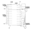
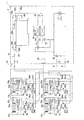
図1は、本発明にかかる熱回収型冷凍装置の一実施形態としての冷暖同時運転型空気調和装置1の概略構成図である。図2は、冷暖同時運転型空気調和装置1を構成する熱源ユニット2の概略の内部構造を示す図である。図3は、熱源側熱交換器24、25の構造を模式的に示す図である。冷暖同時運転型空気調和装置1は、蒸気圧縮式の冷凍サイクル運転を行うことによって、ビル等の室内の冷暖房に使用される装置である。
(1) Configuration of Heat Recovery Refrigeration Device (Cooling and Heating Simultaneous Operation Type Air Conditioner) FIG. 1 is a schematic configuration diagram of a cooling and heating simultaneous operation type air conditioning device 1 as an embodiment of a heat recovery type refrigeration device according to the present invention. It is. FIG. 2 is a diagram showing a schematic internal structure of the heat source unit 2 constituting the cooling / heating simultaneous operation type air conditioner 1. FIG. 3 is a diagram schematically showing the structure of the heat source side heat exchangers 24, 25. The cooling and heating simultaneous operation type air conditioner 1 is an apparatus used for air conditioning in a room such as a building by performing a vapor compression refrigeration cycle operation.

冷暖同時運転型空気調和装置1は、主として、1台の熱源ユニット2と、複数(ここでは、4台)の利用ユニット3a、3b、3c、3dと、各利用ユニット3a、3b、3c、3dに接続される接続ユニット4a、4b、4c、4dと、接続ユニット4a、4b、4c、4dを介して熱源ユニット2と利用ユニット3a、3b、3c、3dとを接続する冷媒連絡管7、8、9とを有している。すなわち、冷暖同時運転型空気調和装置1の蒸気圧縮式の冷媒回路10は、熱源ユニット2と、利用ユニット3a、3b、3c、3dと、接続ユニット4a、4b、4c、4dと、冷媒連絡管7、8、9とが接続されることによって構成されている。そして、冷暖同時運転型空気調和装置1は、各利用ユニット3a、3b、3c、3dが個別に冷房運転又は暖房運転を行うことが可能になっており、暖房運転を行う利用ユニットから冷房運転を行う利用ユニットに冷媒を送ることで利用ユニット間において熱回収を行うこと(ここでは、冷房運転と暖房運転とを同時に行う冷暖同時運転を行うこと)が可能になるように構成されている。しかも、冷暖同時運転型空気調和装置1では、上記の熱回収(冷暖同時運転)も考慮した複数の利用ユニット3a、3b、3c、3d全体の熱負荷に応じて、熱源ユニット2の熱負荷をバランスさせるように構成されている。   The cooling and heating simultaneous operation type air conditioner 1 mainly includes one heat source unit 2, a plurality of (here, four) use units 3 a, 3 b, 3 c, 3 d, and each use unit 3 a, 3 b, 3 c, 3 d. Connecting units 4a, 4b, 4c, and 4d connected to each other, and refrigerant communication tubes 7 and 8 that connect the heat source unit 2 and the utilization units 3a, 3b, 3c, and 3d via the connection units 4a, 4b, 4c, and 4d. , 9. That is, the vapor compression refrigerant circuit 10 of the cooling and heating simultaneous operation type air conditioner 1 includes a heat source unit 2, utilization units 3a, 3b, 3c, and 3d, connection units 4a, 4b, 4c, and 4d, and a refrigerant communication tube. 7, 8 and 9 are connected to each other. In the cooling / heating simultaneous operation type air conditioner 1, each of the use units 3a, 3b, 3c, and 3d can individually perform the cooling operation or the heating operation, and the cooling operation is performed from the use unit that performs the heating operation. Heat is recovered between the utilization units by sending the refrigerant to the utilization unit to be performed (here, simultaneous cooling / heating operation in which the cooling operation and the heating operation are performed simultaneously) is possible. In addition, in the cooling and heating simultaneous operation type air conditioner 1, the heat load of the heat source unit 2 is changed according to the heat loads of the plurality of utilization units 3a, 3b, 3c, and 3d in consideration of the heat recovery (simultaneous cooling and heating operation). It is configured to balance.

<利用ユニット>
利用ユニット3a、3b、3c、3dは、ビル等の室内の天井に埋め込みや吊り下げ等、又は、室内の壁面に壁掛け等により設置されている。利用ユニット3a、3b、3c、3dは、冷媒連絡管7、8、9及び接続ユニット4a、4b、4c、4dを介して熱源ユニット2に接続されており、冷媒回路10の一部を構成している。
<Usage unit>
The use units 3a, 3b, 3c, and 3d are installed by being embedded or suspended in a ceiling of a room such as a building, or by hanging on a wall surface of the room. The utilization units 3a, 3b, 3c, and 3d are connected to the heat source unit 2 via the refrigerant communication tubes 7, 8, and 9 and the connection units 4a, 4b, 4c, and 4d, and constitute a part of the refrigerant circuit 10. ing.

次に、利用ユニット3a、3b、3c、3dの構成について説明する。尚、利用ユニット3aと利用ユニット3b、3c、3dとは同様の構成であるため、ここでは、利用ユニット3aの構成のみ説明し、利用ユニット3b、3c、3dの構成については、それぞれ、利用ユニット3aの各部を示す符号の添字「a」の代わりに、「b」、「c」又は「d」の添字を付して、各部の説明を省略する。   Next, the configuration of the usage units 3a, 3b, 3c, and 3d will be described. Since the usage unit 3a and the usage units 3b, 3c, and 3d have the same configuration, only the configuration of the usage unit 3a will be described here, and the configuration of the usage units 3b, 3c, and 3d will be described respectively. Instead of the subscript “a” indicating the respective parts of 3a, the subscript “b”, “c” or “d” is attached, and the description of each part is omitted.

利用ユニット3aは、主として、冷媒回路10の一部を構成しており、利用側冷媒回路13a(利用ユニット3b、3c、3dでは、それぞれ、利用側冷媒回路13b、13c、13d)を有している。利用側冷媒回路13aは、主として、利用側流量調節弁51aと、利用側熱交換器52aとを有している。   The usage unit 3a mainly constitutes a part of the refrigerant circuit 10, and includes usage-side refrigerant circuits 13a (in the usage units 3b, 3c, and 3d, usage-side refrigerant circuits 13b, 13c, and 13d, respectively). Yes. The utilization side refrigerant circuit 13a mainly has a utilization side flow rate adjustment valve 51a and a utilization side heat exchanger 52a.

利用側流量調節弁51aは、利用側熱交換器52aを流れる冷媒の流量の調節等を行うために、利用側熱交換器52aの液側に接続された開度調節が可能な電動膨張弁である。   The usage-side flow rate adjustment valve 51a is an electric expansion valve that can adjust the opening degree connected to the liquid side of the usage-side heat exchanger 52a in order to adjust the flow rate of the refrigerant flowing through the usage-side heat exchanger 52a. is there.

利用側熱交換器52aは、冷媒と室内空気との熱交換を行うための機器であり、例えば、多数の伝熱管及びフィンによって構成されたフィン・アンド・チューブ型熱交換器からなる。ここで、利用ユニット3aは、ユニット内に室内空気を吸入して、熱交換した後に、供給空気として屋内に供給するための室内ファン53aを有しており、室内空気と利用側熱交換器32aを流れる冷媒とを熱交換させることが可能である。室内ファン53aは、室内ファンモータ54aによって駆動される。   The use-side heat exchanger 52a is a device for performing heat exchange between the refrigerant and the room air, and includes, for example, a fin-and-tube heat exchanger configured by a large number of heat transfer tubes and fins. Here, the utilization unit 3a has an indoor fan 53a for sucking indoor air into the unit and exchanging heat, and then supplying the indoor air as supply air to the indoor unit 53a. It is possible to exchange heat with the refrigerant flowing through The indoor fan 53a is driven by the indoor fan motor 54a.

また、利用ユニット3aは、利用ユニット3aを構成する各部51a、54aの動作を制御する利用側制御部50aを有している。そして、利用側制御部50aは、利用ユニット3aの制御を行うために設けられたマイクロコンピュータやメモリを有しており、リモコン(図示せず)との間で制御信号等のやりとりを行ったり、熱源ユニット2との間で制御信号等のやりとりを行うことができるようになっている。   In addition, the usage unit 3a includes a usage-side control unit 50a that controls the operations of the units 51a and 54a constituting the usage unit 3a. The use-side control unit 50a includes a microcomputer and a memory provided for controlling the use unit 3a, and exchanges control signals and the like with a remote controller (not shown). Control signals and the like can be exchanged with the heat source unit 2.

<熱源ユニット>
熱源ユニット2は、ビル等の屋上等に設置されており、冷媒連絡管7、8、9を介して利用ユニット3a、3b、3c、3dに接続されており、利用ユニット3a、3b、3c、3dとの間で冷媒回路10を構成している。
<Heat source unit>
The heat source unit 2 is installed on the rooftop of a building or the like, and is connected to the usage units 3a, 3b, 3c, and 3d via the refrigerant communication tubes 7, 8, and 9, and the usage units 3a, 3b, 3c, The refrigerant circuit 10 is configured with 3d.

次に、熱源ユニット2の構成について説明する。熱源ユニット2は、主として、冷媒回路10の一部を構成しており、熱源側冷媒回路12を有している。熱源側冷媒回路12は、主として、圧縮機21と、複数(ここでは、2つ)の熱交切換機構22、23と、複数(ここでは、2つ)の熱源側熱交換器24、25と、複数(ここでは、2つ)の熱源側流量調節弁26、27と、レシーバ28と、ブリッジ回路29と、高低圧切換機構30と、液側閉鎖弁31と、高低圧ガス側閉鎖弁32と、低圧ガス側閉鎖弁33とを有している。   Next, the configuration of the heat source unit 2 will be described. The heat source unit 2 mainly constitutes a part of the refrigerant circuit 10 and has a heat source side refrigerant circuit 12. The heat source side refrigerant circuit 12 mainly includes a compressor 21, a plurality (here, two) heat exchange switching mechanisms 22, 23, and a plurality (here, two) heat source side heat exchangers 24, 25, , A plurality of (here, two) heat source side flow control valves 26 and 27, a receiver 28, a bridge circuit 29, a high / low pressure switching mechanism 30, a liquid side closing valve 31, and a high / low pressure gas side closing valve 32. And a low-pressure gas side closing valve 33.

圧縮機21は、ここでは、冷媒を圧縮するための機器であり、例えば、圧縮機モータ21aをインバータ制御することで運転容量を可変することが可能なスクロール型等の容積式圧縮機からなる。   Here, the compressor 21 is a device for compressing the refrigerant, and includes, for example, a scroll type positive displacement compressor capable of changing the operation capacity by inverter-controlling the compressor motor 21a.

第1熱交切換機構22は、第1熱源側熱交換器24を冷媒の放熱器として機能させる場合(以下、「放熱運転状態」とする)には圧縮機21の吐出側と第1熱源側熱交換器24のガス側とを接続し(図1の第1熱交切換機構22の実線を参照)、第1熱源側熱交換器24を冷媒の蒸発器として機能させる場合(以下、「蒸発運転状態」とする)には圧縮機21の吸入側と第1熱源側熱交換器24のガス側とを接続するように(図1の第1熱交切換機構22の破線を参照)、熱源側冷媒回路12内における冷媒の流路を切り換えることが可能な機器であり、例えば、四路切換弁からなる。また、第2熱交切換機構23は、第2熱源側熱交換器25を冷媒の放熱器として機能させる場合(以下、「放熱運転状態」とする)には圧縮機21の吐出側と第2熱源側熱交換器25のガス側とを接続し(図1の第2熱交切換機構23の実線を参照)、第2熱源側熱交換器25を冷媒の蒸発器として機能させる場合(以下、「蒸発運転状態」とする)には圧縮機21の吸入側と第2熱源側熱交換器25のガス側とを接続するように(図1の第2熱交切換機構23の破線を参照)、熱源側冷媒回路12内における冷媒の流路を切り換えることが可能な機器であり、例えば、四路切換弁からなる。そして、第1熱交切換機構22及び第2熱交切換機構23の切り換え状態を変更することによって、第1熱源側熱交換器24及び第2熱源側熱交換器25は、個別に冷媒の蒸発器又は放熱器として機能させる切り換えが可能になっている。   When the first heat exchanger switching mechanism 22 causes the first heat source side heat exchanger 24 to function as a refrigerant radiator (hereinafter referred to as “heat dissipation operation state”), the discharge side and the first heat source side of the compressor 21 are used. When the gas side of the heat exchanger 24 is connected (see the solid line of the first heat exchange switching mechanism 22 in FIG. 1) and the first heat source side heat exchanger 24 functions as a refrigerant evaporator (hereinafter referred to as “evaporation”). In the “operating state”, the suction side of the compressor 21 and the gas side of the first heat source side heat exchanger 24 are connected (see the broken line of the first heat exchange switching mechanism 22 in FIG. 1). This is a device capable of switching the refrigerant flow path in the side refrigerant circuit 12, and is composed of, for example, a four-way switching valve. The second heat exchange switching mechanism 23 is connected to the discharge side of the compressor 21 and the second side when the second heat source side heat exchanger 25 functions as a refrigerant radiator (hereinafter referred to as “heat dissipation operation state”). When connecting the gas side of the heat source side heat exchanger 25 (see the solid line of the second heat exchange switching mechanism 23 in FIG. 1), and causing the second heat source side heat exchanger 25 to function as a refrigerant evaporator (hereinafter, referred to as a refrigerant evaporator) In the “evaporation operation state”, the suction side of the compressor 21 and the gas side of the second heat source side heat exchanger 25 are connected (see the broken line of the second heat exchange switching mechanism 23 in FIG. 1). The device is capable of switching the refrigerant flow path in the heat source side refrigerant circuit 12, and is composed of, for example, a four-way switching valve. Then, by changing the switching state of the first heat exchange switching mechanism 22 and the second heat exchange switching mechanism 23, the first heat source side heat exchanger 24 and the second heat source side heat exchanger 25 individually evaporate the refrigerant. Switching to function as a heat sink or a radiator is possible.

第1熱源側熱交換器24は、冷媒と室外空気との熱交換を行うための機器であり、例えば、多数の伝熱管及びフィンによって構成されたフィン・アンド・チューブ型熱交換器からなる。第1熱源側熱交換器24は、そのガス側が第1熱交切換機構22に接続され、その液側が第1熱源側流量調節弁26に接続されている。具体的には、第1熱源側熱交換器24のガス側は、第1熱源側熱交換器24を構成する複数の伝熱管との間で冷媒の合流及び分岐を行うための第1ヘッダ24aが設けられており、第1ヘッダ24aが第1熱交切換機構22に接続されている。第1熱源側熱交換器24の液側は、第1熱源側熱交換器24を構成する複数の伝熱管との間で冷媒の合流及び分岐を行うための第1分流器24bが設けられており、第1分流器24bが第1熱源側流量調節弁26に接続されている。また、第2熱源側熱交換器25は、冷媒と室外空気との熱交換を行うための機器であり、例えば、多数の伝熱管及びフィンによって構成されたフィン・アンド・チューブ型熱交換器からなる。第2熱源側熱交換器25は、そのガス側が第2熱交切換機構23に接続され、その液側が第2熱源側流量調節弁27に接続されている。具体的には、第2熱源側熱交換器25のガス側は、第2熱源側熱交換器25を構成する複数の伝熱管との間で冷媒の合流及び分岐を行うための第2ヘッダ25aが設けられており、第2ヘッダ25aが第2熱交切換機構23に接続されている。第2熱源側熱交換器25の液側は、第2熱源側熱交換器25を構成する複数の伝熱管との間で冷媒の合流及び分岐を行うための第2分流器25bが設けられており、第2分流器25bが第2熱源側流量調節弁27に接続されている。   The first heat source side heat exchanger 24 is a device for performing heat exchange between the refrigerant and the outdoor air, and includes, for example, a fin-and-tube heat exchanger constituted by a large number of heat transfer tubes and fins. The gas side of the first heat source side heat exchanger 24 is connected to the first heat exchange switching mechanism 22, and the liquid side thereof is connected to the first heat source side flow rate adjustment valve 26. Specifically, the gas side of the first heat source side heat exchanger 24 is a first header 24a for merging and branching refrigerant with a plurality of heat transfer tubes constituting the first heat source side heat exchanger 24. Is provided, and the first header 24 a is connected to the first heat exchange switching mechanism 22. The liquid side of the first heat source side heat exchanger 24 is provided with a first flow divider 24b for merging and branching the refrigerant with a plurality of heat transfer tubes constituting the first heat source side heat exchanger 24. The first flow divider 24b is connected to the first heat source side flow rate adjustment valve 26. The second heat source side heat exchanger 25 is a device for performing heat exchange between the refrigerant and the outdoor air. For example, the second heat source side heat exchanger 25 includes a fin-and-tube heat exchanger constituted by a large number of heat transfer tubes and fins. Become. The gas side of the second heat source side heat exchanger 25 is connected to the second heat exchange switching mechanism 23, and the liquid side thereof is connected to the second heat source side flow rate adjustment valve 27. Specifically, the gas side of the second heat source side heat exchanger 25 has a second header 25a for merging and branching the refrigerant with a plurality of heat transfer tubes constituting the second heat source side heat exchanger 25. The second header 25 a is connected to the second heat exchange switching mechanism 23. The liquid side of the second heat source side heat exchanger 25 is provided with a second flow divider 25b for merging and branching the refrigerant with a plurality of heat transfer tubes constituting the second heat source side heat exchanger 25. The second flow divider 25 b is connected to the second heat source side flow rate adjustment valve 27.

ここで、第1熱源側熱交換器24と第2熱源側熱交換器25とは、熱交換容量が異なっており、第1熱源側熱交換器24よりも第2熱源側熱交換器25の熱交換容量のほうが大きい。具体的には、第2熱源側熱交換器25は、第1熱源側熱交換器の1.8倍〜4.0倍の熱交換容量を有している。また、熱交換容量が小さい第1熱源側熱交換器24は、熱交換容量が大きい第2熱源側熱交換器25の上側に配置されている。具体的には、第1熱源側熱交換器24と第2熱源側熱交換器25とを一体の熱源側熱交換器として構成し、その上部を構成する伝熱管を第1ヘッダ24a及び第1分流器24bに接続することで第1熱源側熱交換器24として機能させ、その下部を構成する伝熱管を第2ヘッダ25a及び第2分流器25bに接続することで第2熱源側熱交換器25として機能させるようにしている。また、第2ヘッダ25aは、第1ヘッダ24aよりも流路断面積が大きい。具体的には、第2ヘッダ25aの内径サイズを第1ヘッダ24aの内径サイズよりも大きくしている。そして、熱源ユニット2は、ユニット内に室外空気を吸入して、熱交換した後に、ユニット外に排出するための室外ファン34を有しており、室外空気と熱源側熱交換器24、25を流れる冷媒とを熱交換させることが可能である。室外ファン34は、室外ファンモータ34aによって駆動される。ここで、熱源ユニット2の側面には、室外空気を吸入するための吸入口2aが形成されており、熱源ユニット2の天面には、室外空気を排出するための排出口2bが形成されており、室外ファン34は、熱源ユニット2の上部に配置されている。   Here, the first heat source side heat exchanger 24 and the second heat source side heat exchanger 25 have different heat exchange capacities, and the second heat source side heat exchanger 25 has a heat exchange capacity different from that of the first heat source side heat exchanger 24. The heat exchange capacity is larger. Specifically, the second heat source side heat exchanger 25 has a heat exchange capacity 1.8 times to 4.0 times that of the first heat source side heat exchanger. Moreover, the 1st heat source side heat exchanger 24 with a small heat exchange capacity | capacitance is arrange | positioned above the 2nd heat source side heat exchanger 25 with a large heat exchange capacity | capacitance. Specifically, the first heat source side heat exchanger 24 and the second heat source side heat exchanger 25 are configured as an integrated heat source side heat exchanger, and the heat transfer tubes constituting the upper part thereof are the first header 24a and the first heat exchanger tube. The second heat source side heat exchanger is made to function as the first heat source side heat exchanger 24 by connecting to the flow divider 24b, and the heat transfer tube constituting the lower part thereof is connected to the second header 25a and the second flow divider 25b. It is made to function as 25. Further, the second header 25a has a larger channel cross-sectional area than the first header 24a. Specifically, the inner diameter size of the second header 25a is made larger than the inner diameter size of the first header 24a. The heat source unit 2 has an outdoor fan 34 for sucking outdoor air into the unit, exchanging heat, and then discharging the air outside the unit. The outdoor air and the heat source side heat exchangers 24 and 25 are connected to the heat source unit 2. It is possible to exchange heat with the flowing refrigerant. The outdoor fan 34 is driven by an outdoor fan motor 34a. Here, a suction port 2 a for sucking outdoor air is formed on the side surface of the heat source unit 2, and a discharge port 2 b for discharging outdoor air is formed on the top surface of the heat source unit 2. The outdoor fan 34 is disposed on the upper part of the heat source unit 2.

第1熱源側流量調節弁26は、第1熱源側熱交換器24を流れる冷媒の流量の調節等を行うために、第1熱源側熱交換器24の液側に接続された開度調節が可能な電動膨張弁である。また、第2熱源側流量調節弁27は、第2熱源側熱交換器25を流れる冷媒の流量の調節等を行うために、第2熱源側熱交換器25の液側に接続された開度調節が可能な電動膨張弁である。ここで、第1熱源側流量調節弁26と第2熱源側流量調節弁27とは、定格Cv値が異なっており、第1熱源側流量調節弁26よりも第2熱源側流量調節弁27の定格Cv値のほうが大きい。   The first heat source side flow rate adjustment valve 26 is configured to adjust the opening degree connected to the liquid side of the first heat source side heat exchanger 24 in order to adjust the flow rate of the refrigerant flowing through the first heat source side heat exchanger 24. It is a possible electric expansion valve. The second heat source side flow rate adjustment valve 27 has an opening degree connected to the liquid side of the second heat source side heat exchanger 25 in order to adjust the flow rate of the refrigerant flowing through the second heat source side heat exchanger 25 and the like. It is an electric expansion valve that can be adjusted. Here, the first heat source side flow rate adjustment valve 26 and the second heat source side flow rate adjustment valve 27 have different rated Cv values, and the second heat source side flow rate adjustment valve 27 has a higher rated Cv value than the first heat source side flow rate adjustment valve 26. The rated Cv value is larger.

レシーバ28は、熱源側熱交換器24、25と利用側冷媒回路13a、13b、13c、13dとの間を流れる冷媒を一時的に溜めるための容器である。レシーバ28の上部には、レシーバ入口管28aが設けられており、レシーバ28の下部には、レシーバ出口管28bが設けられている。また、レシーバ入口管28aには、開閉制御が可能なレシーバ入口開閉弁28cが設けられている。そして、レシーバ28の入口管28a及び出口管28bは、ブリッジ回路29を介して、熱源側熱交換器24、25と液側閉鎖弁31との間に接続されている。   The receiver 28 is a container for temporarily storing the refrigerant flowing between the heat source side heat exchangers 24 and 25 and the use side refrigerant circuits 13a, 13b, 13c, and 13d. A receiver inlet pipe 28 a is provided in the upper part of the receiver 28, and a receiver outlet pipe 28 b is provided in the lower part of the receiver 28. The receiver inlet pipe 28a is provided with a receiver inlet on / off valve 28c capable of opening / closing control. The inlet pipe 28 a and the outlet pipe 28 b of the receiver 28 are connected between the heat source side heat exchangers 24 and 25 and the liquid side shut-off valve 31 via the bridge circuit 29.

ブリッジ回路29は、冷媒が熱源側熱交換器24、25側から液側閉鎖弁31側に向かって流れる場合、及び、冷媒が液側閉鎖弁31側から熱源側熱交換器24、25側に向かって流れる場合のいずれにおいても、レシーバ入口管28aを通じてレシーバ28内に冷媒を流入させ、レシーバ出口管28bを通じてレシーバ28内から冷媒を流出させる機能を有する回路である。ブリッジ回路29は、4つの逆止弁29a、29b、29c、29dを有している。そして、入口逆止弁29aは、熱源側熱交換器24、25側からレシーバ入口管28aへの冷媒の流通のみを許容する逆止弁である。入口逆止弁29bは、液側閉鎖弁31側からレシーバ入口管28aへの冷媒の流通のみを許容する逆止弁である。すなわち、入口逆止弁29a、29bは、熱源側熱交換器24、25側又は液側閉鎖弁31側からレシーバ入口管28aに冷媒を流通させる機能を有している。出口逆止弁29cは、レシーバ出口管28bから液側閉鎖弁31側への冷媒の流通のみを許容する逆止弁である。出口逆止弁29dは、レシーバ出口管28bから熱源側熱交換器24、25側への冷媒の流通のみを許容する逆止弁である。すなわち、出口逆止弁29c、29dは、レシーバ出口管28bから熱源側熱交換器24、25側又は液側閉鎖弁31側に冷媒を流通させる機能を有している。   In the bridge circuit 29, when the refrigerant flows from the heat source side heat exchangers 24, 25 toward the liquid side closing valve 31 side, and when the refrigerant flows from the liquid side closing valve 31 side to the heat source side heat exchangers 24, 25 side. In any case where the refrigerant flows in the direction, the refrigerant has a function of causing the refrigerant to flow into the receiver 28 through the receiver inlet pipe 28a and out of the receiver 28 through the receiver outlet pipe 28b. The bridge circuit 29 has four check valves 29a, 29b, 29c, and 29d. The inlet check valve 29a is a check valve that only allows the refrigerant to flow from the heat source side heat exchangers 24 and 25 to the receiver inlet pipe 28a. The inlet check valve 29b is a check valve that only allows refrigerant to flow from the liquid-side closing valve 31 side to the receiver inlet pipe 28a. That is, the inlet check valves 29a and 29b have a function of circulating the refrigerant from the heat source side heat exchangers 24 and 25 side or the liquid side closing valve 31 side to the receiver inlet pipe 28a. The outlet check valve 29c is a check valve that allows only the refrigerant to flow from the receiver outlet pipe 28b to the liquid side closing valve 31 side. The outlet check valve 29d is a check valve that only allows refrigerant to flow from the receiver outlet pipe 28b to the heat source side heat exchangers 24 and 25. That is, the outlet check valves 29c and 29d have a function of circulating the refrigerant from the receiver outlet pipe 28b to the heat source side heat exchangers 24 and 25 side or the liquid side closing valve 31 side.

高低圧切換機構30は、圧縮機21から吐出された高圧のガス冷媒を利用側冷媒回路13a、13b、13c、13dに送る場合(以下、「放熱負荷主体運転状態」とする)には、圧縮機21の吐出側と高低圧ガス側閉鎖弁32とを接続し(図1の高低圧切換機構30の破線を参照)、圧縮機21から吐出された高圧のガス冷媒を利用側冷媒回路13a、13b、13c、13dに送らない場合(以下、「蒸発負荷主体運転状態」とする)には、高低圧ガス側閉鎖弁32と圧縮機21の吸入側とを接続するように(図1の高低圧切換機構30の実線を参照)、熱源側冷媒回路12内における冷媒の流路を切り換えることが可能な機器であり、例えば、四路切換弁からなる。   The high / low pressure switching mechanism 30 compresses the high-pressure gas refrigerant discharged from the compressor 21 when the high-pressure gas refrigerant is sent to the use-side refrigerant circuits 13a, 13b, 13c, and 13d (hereinafter referred to as “radiation load main operation state”). The discharge side of the compressor 21 and the high / low pressure gas side shut-off valve 32 (see the broken line of the high / low pressure switching mechanism 30 in FIG. 1), and the high pressure gas refrigerant discharged from the compressor 21 is used on the use side refrigerant circuit 13a, When not sent to 13b, 13c, 13d (hereinafter referred to as "evaporative load main operation state"), the high / low pressure gas side shut-off valve 32 and the suction side of the compressor 21 are connected (high in FIG. 1). (Refer to the solid line of the low-pressure switching mechanism 30), which is a device capable of switching the refrigerant flow path in the heat source side refrigerant circuit 12, and includes, for example, a four-way switching valve.

液側閉鎖弁31、高低圧ガス側閉鎖弁32及び低圧ガス側閉鎖弁33は、外部の機器・配管(具体的には、冷媒連絡管7、8及び9)との接続口に設けられた弁である。液側閉鎖弁31は、ブリッジ回路29を介してレシーバ入口管28a又はレシーバ出口管28bに接続されている。高低圧ガス側閉鎖弁32は、高低圧切換機構30に接続されている。低圧ガス側閉鎖弁33は、圧縮機21の吸入側に接続されている。   The liquid side shut-off valve 31, the high-low pressure gas side shut-off valve 32, and the low-pressure gas side shut-off valve 33 are provided at the connection ports with external devices and piping (specifically, the refrigerant communication pipes 7, 8, and 9). It is a valve. The liquid side closing valve 31 is connected to the receiver inlet pipe 28a or the receiver outlet pipe 28b via the bridge circuit 29. The high / low pressure gas side closing valve 32 is connected to the high / low pressure switching mechanism 30. The low pressure gas side closing valve 33 is connected to the suction side of the compressor 21.

また、熱源ユニット2は、熱源ユニット2を構成する各部21a、22、23、26、27、28c、30、34aの動作を制御する熱源側制御部20を有している。そして、熱源側制御部20は、熱源ユニット2の制御を行うために設けられたマイクロコンピュータやメモリを有しており、利用ユニット3a、3b、3c、3dの利用側制御部50a、50b、50c、50dとの間で制御信号等のやりとりを行うことができるようになっている。   Further, the heat source unit 2 includes a heat source side control unit 20 that controls the operation of each unit 21 a, 22, 23, 26, 27, 28 c, 30, 34 a constituting the heat source unit 2. The heat source side control unit 20 includes a microcomputer and a memory provided to control the heat source unit 2, and uses side control units 50a, 50b, 50c of the usage units 3a, 3b, 3c, 3d. , 50d can exchange control signals and the like.

<接続ユニット>
接続ユニット4a、4b、4c、4dは、ビル等の室内に利用ユニット3a、3b、3c、3dとともに設置されている。接続ユニット4a、4b、4c、4dは、冷媒連絡管9、10、11とともに、利用ユニット3、4、5と熱源ユニット2との間に介在しており、冷媒回路10の一部を構成している。
<Connection unit>
The connection units 4a, 4b, 4c, and 4d are installed together with the use units 3a, 3b, 3c, and 3d in a room such as a building. The connection units 4 a, 4 b, 4 c, 4 d are interposed between the use units 3, 4, 5 and the heat source unit 2 together with the refrigerant communication tubes 9, 10, 11, and constitute a part of the refrigerant circuit 10. ing.

次に、接続ユニット4a、4b、4c、4dの構成について説明する。尚、接続ユニット4aと接続ユニット4b、4c、4dとは同様の構成であるため、ここでは、接続ユニット4aの構成のみ説明し、接続ユニット4b、4c、4dの構成については、それぞれ、接続ユニット4aの各部を示す符号の添字「a」の代わりに、「b」、「c」又は「d」の添字を付して、各部の説明を省略する。   Next, the configuration of the connection units 4a, 4b, 4c, and 4d will be described. Since the connection unit 4a and the connection units 4b, 4c, and 4d have the same configuration, only the configuration of the connection unit 4a will be described here, and the configuration of the connection units 4b, 4c, and 4d will be described respectively. In place of the subscript “a” indicating the respective parts of 4a, the subscript “b”, “c” or “d” is attached, and the description of each part is omitted.

接続ユニット4aは、主として、冷媒回路10の一部を構成しており、接続側冷媒回路14a(接続ユニット4b、4c、4dでは、それぞれ、接続側冷媒回路14b、14c、14d)を有している。接続側冷媒回路14aは、主として、液接続管61aと、ガス接続管62aとを有している。   The connection unit 4a mainly constitutes a part of the refrigerant circuit 10, and includes a connection side refrigerant circuit 14a (in the connection units 4b, 4c, and 4d, connection side refrigerant circuits 14b, 14c, and 14d, respectively). Yes. The connection side refrigerant circuit 14a mainly includes a liquid connection pipe 61a and a gas connection pipe 62a.

液接続管61aは、液冷媒連絡管7と利用側冷媒回路13aの利用側流量調節弁51aとを接続している。   The liquid connection pipe 61a connects the liquid refrigerant communication pipe 7 and the use side flow rate adjustment valve 51a of the use side refrigerant circuit 13a.

ガス接続管62aは、高低圧ガス冷媒連絡管8に接続された高圧ガス接続管63aと、低圧ガス冷媒連絡管9に接続された低圧ガス接続管64aと、高圧ガス接続管63aと低圧ガス接続管64aとを合流させる合流ガス接続管65aとを有している。合流ガス接続管65aは、利用側冷媒回路13aの利用側熱交換器52aのガス側に接続されている。高圧ガス接続管63aには、開閉制御が可能な高圧ガス開閉弁66aが設けられており、低圧ガス接続管64aには、開閉制御が可能な低圧ガス開閉弁67aが設けられている。   The gas connection pipe 62a includes a high pressure gas connection pipe 63a connected to the high and low pressure gas refrigerant communication pipe 8, a low pressure gas connection pipe 64a connected to the low pressure gas refrigerant communication pipe 9, and a high pressure gas connection pipe 63a and a low pressure gas connection. It has a merged gas connection pipe 65a that merges the pipe 64a. The merged gas connection pipe 65a is connected to the gas side of the use side heat exchanger 52a of the use side refrigerant circuit 13a. The high pressure gas connection pipe 63a is provided with a high pressure gas on / off valve 66a capable of opening / closing control, and the low pressure gas connection pipe 64a is provided with a low pressure gas on / off valve 67a capable of opening / closing control.

そして、接続ユニット4aは、利用ユニット3aが冷房運転を行う際には、低圧ガス開閉弁67aを開けた状態にして、液冷媒連絡管7を通じて液接続管61aに流入する冷媒を利用側冷媒回路13aの利用側流量調節弁51aを通じて利用側熱交換器52aに送り、利用側熱交換器52aにおいて室内空気との熱交換によって蒸発した冷媒を、合流ガス接続管65a及び低圧ガス接続管64aを通じて、低圧ガス冷媒連絡管9に戻すように機能することができる。また、接続ユニット4aは、利用ユニット3aが暖房運転を行う際には、低圧ガス開閉弁67aを閉止し、かつ、高圧ガス開閉弁66aを開けた状態にして、高低圧ガス冷媒連絡管8を通じて高圧ガス接続管63a及び合流ガス接続管65aに流入する冷媒を利用側冷媒回路13aの利用側熱交換器52aに送り、利用側熱交換器52aにおいて室内空気との熱交換によって放熱した冷媒を、利用側流量調節弁51a及び液接続管61aを通じて、液冷媒連絡管7に戻すように機能することができる。この機能は、接続ユニット4aだけでなく、接続ユニット4b、4c、4dも同様に有しているため、接続ユニット4a、4b、4c、4dによって、利用側熱交換器52a、52b、52c、52dは、個別に冷媒の蒸発器又は放熱器として機能させる切り換えが可能になっている。   When the use unit 3a performs the cooling operation, the connection unit 4a opens the low-pressure gas on / off valve 67a and allows the refrigerant flowing into the liquid connection pipe 61a through the liquid refrigerant communication pipe 7 to be used on the use-side refrigerant circuit. The refrigerant evaporated by heat exchange with the indoor air in the use side heat exchanger 52a through the use side flow rate adjustment valve 51a of 13a and through the combined gas connection pipe 65a and the low pressure gas connection pipe 64a is sent through the use side heat exchanger 52a. It can function to return to the low-pressure gas refrigerant communication tube 9. Further, the connection unit 4a closes the low pressure gas on / off valve 67a and opens the high pressure gas on / off valve 66a when the use unit 3a performs the heating operation, and passes through the high / low pressure gas refrigerant communication pipe 8. The refrigerant flowing into the high-pressure gas connection pipe 63a and the merged gas connection pipe 65a is sent to the use-side heat exchanger 52a of the use-side refrigerant circuit 13a, and the refrigerant radiated by heat exchange with room air in the use-side heat exchanger 52a is It can function to return to the liquid refrigerant communication pipe 7 through the use side flow rate adjustment valve 51a and the liquid connection pipe 61a. Since this function has not only the connection unit 4a but also the connection units 4b, 4c, and 4d, the use side heat exchangers 52a, 52b, 52c, and 52d are connected by the connection units 4a, 4b, 4c, and 4d. Can be switched individually to function as a refrigerant evaporator or radiator.

また、接続ユニット4aは、接続ユニット4aを構成する各部66a、67aの動作を制御する接続側制御部60aを有している。そして、接続側制御部60aは、接続ユニット60aの制御を行うために設けられたマイクロコンピュータやメモリを有しており、利用ユニット3aの利用側制御部50aとの間で制御信号等のやりとりを行うことができるようになっている。   Moreover, the connection unit 4a has the connection side control part 60a which controls operation | movement of each part 66a, 67a which comprises the connection unit 4a. The connection-side control unit 60a includes a microcomputer and a memory provided for controlling the connection unit 60a, and exchanges control signals and the like with the use-side control unit 50a of the use unit 3a. Can be done.

以上のように、利用側冷媒回路13a、13b、13c、13dと、熱源側冷媒回路12と、冷媒連絡管7、8、9と、接続側冷媒回路14a、14b、14c、14dとが接続されて、冷暖同時運転型空気調和装置1の冷媒回路10が構成されている。そして、冷暖同時運転型空気調和装置1では、例えば、利用ユニット3a、3bが冷房運転を行いつつ、利用ユニット3c、3dが暖房運転を行う冷暖同時運転を行うことが可能になっている。このとき、冷媒の放熱器として機能する利用側熱交換器52a、52bから冷媒の蒸発器として機能する利用側熱交換器52c、52dに冷媒を送ることで利用ユニット3a、3b、3c、3d間において熱回収が行われている。すなわち、冷暖同時運転型空気調和装置1は、圧縮機21と、個別に冷媒の蒸発器又は放熱器として機能させる切り換えが可能な複数(ここでは、2つ)の熱源側熱交換器24、25と、個別に冷媒の蒸発器又は放熱器として機能させる切り換えが可能な複数(ここでは、4つ)の利用側熱交換器52a、52b、52c、52dとを含んでおり、冷媒の放熱器として機能する利用側熱交換器から冷媒の蒸発器として機能する利用側熱交換器に冷媒を送ることで利用側熱交換器間において熱回収を行うことが可能な熱回収型冷凍装置を構成している。そして、ここでは、上記のように、第2熱源側熱交換器25を第1熱源側熱交換器24の熱交換容量の1.8倍以上にしている。   As described above, the use side refrigerant circuits 13a, 13b, 13c, 13d, the heat source side refrigerant circuit 12, the refrigerant communication tubes 7, 8, 9 and the connection side refrigerant circuits 14a, 14b, 14c, 14d are connected. Thus, the refrigerant circuit 10 of the cooling and heating simultaneous operation type air conditioner 1 is configured. In the cooling / heating simultaneous operation type air conditioner 1, for example, it is possible to perform the cooling / heating simultaneous operation in which the utilization units 3a, 3b perform the heating operation while the utilization units 3a, 3b perform the cooling operation. At this time, between the use units 3a, 3b, 3c and 3d by sending the refrigerant from the use side heat exchangers 52a and 52b functioning as a refrigerant radiator to the use side heat exchangers 52c and 52d functioning as a refrigerant evaporator Heat recovery is performed in That is, the cooling and heating simultaneous operation type air conditioner 1 has a compressor 21 and a plurality of (here, two) heat source side heat exchangers 24 and 25 that can be switched to function individually as refrigerant evaporators or radiators. And a plurality of (in this case, four) use-side heat exchangers 52a, 52b, 52c, and 52d that can be switched to function as refrigerant evaporators or radiators. Constructing a heat recovery refrigeration system capable of recovering heat between the use side heat exchangers by sending the refrigerant from the functioning use side heat exchanger to the use side heat exchanger functioning as a refrigerant evaporator Yes. Here, as described above, the second heat source side heat exchanger 25 is set to 1.8 times or more the heat exchange capacity of the first heat source side heat exchanger 24.

(2)熱回収型冷凍装置(冷暖同時運転型空気調和装置)の動作
次に、冷暖同時運転型空気調和装置1の動作について説明する。
(2) Operation of Heat Recovery Refrigeration Device (Cooling and Heating Simultaneous Operation Type Air Conditioner) Next, the operation of the cooling and heating simultaneous operation type air conditioner 1 will be described.

冷暖同時運転型空気調和装置1の運転モードは、冷房運転モード(蒸発負荷大)と、冷房運転モード(蒸発負荷小)と、暖房運転モード(放熱負荷大)と、暖房運転モード(放熱負荷小)と、冷暖同時運転モード(蒸発負荷主体)と、冷暖同時運転モード(放熱負荷主体)と、冷暖同時運転モード(蒸発・放熱負荷均衡)とに分けることができる。ここで、冷房運転モード(蒸発負荷大)は、冷房運転(すなわち、利用側熱交換器が冷媒の蒸発器として機能する運転)を行う利用ユニットだけが存在し、利用ユニット全体の蒸発負荷に対して熱源側熱交換器24、25の両方を冷媒の放熱器として機能させる運転モードである。冷房運転モード(蒸発負荷小)は、冷房運転(すなわち、利用側熱交換器が冷媒の蒸発器として機能する運転)を行う利用ユニットだけが存在し、利用ユニット全体の蒸発負荷に対して第1熱源側熱交換器24だけを冷媒の放熱器として機能させる運転モードである。暖房運転モード(放熱負荷大)は、暖房運転(すなわち、利用側熱交換器が冷媒の放熱器として機能する運転)を行う利用ユニットだけが存在し、利用ユニット全体の放熱負荷に対して熱源側熱交換器24、25の両方を冷媒の蒸発器として機能させる運転モードである。暖房運転モード(放熱負荷小)は、暖房運転(すなわち、利用側熱交換器が冷媒の放熱器として機能する運転)を行う利用ユニットだけが存在し、利用ユニット全体の放熱負荷に対して第1熱源側熱交換器24だけを冷媒の蒸発器として機能させる運転モードである。冷暖同時運転モード(蒸発負荷主体)は、冷房運転(すなわち、利用側熱交換器が冷媒の蒸発器として機能する運転)を行う利用ユニットと暖房運転(すなわち、利用側熱交換器が冷媒の放熱器として機能する運転)を行う利用ユニットとが混在し、利用ユニット全体の熱負荷が蒸発負荷主体である場合に、この利用ユニット全体の蒸発負荷に対して第1熱源側熱交換器24だけを冷媒の放熱器として機能させる運転モードである。冷暖同時運転モード(放熱負荷主体)は、冷房運転(すなわち、利用側熱交換器が冷媒の蒸発器として機能する運転)を行う利用ユニットと暖房運転(すなわち、利用側熱交換器が冷媒の放熱器として機能する運転)を行う利用ユニットとが混在し、利用ユニット全体の熱負荷が放熱負荷主体である場合に、この利用ユニット全体の放熱負荷に対して第1熱源側熱交換器24だけを冷媒の蒸発器として機能させる運転モードである。冷暖同時運転モード(蒸発・放熱負荷均衡)は、冷房運転(すなわち、利用側熱交換器が冷媒の蒸発器として機能する運転)を行う利用ユニットと暖房運転(すなわち、利用側熱交換器が冷媒の放熱器として機能する運転)を行う利用ユニットとが混在し、利用ユニット全体の蒸発負荷と放熱負荷とが均衡する場合に、第1熱源側熱交換器24を冷媒の放熱器として機能させ、かつ、第2熱源側熱交換器25を冷媒の蒸発器として機能させる運転モードである。   The operation modes of the cooling and heating simultaneous operation type air conditioner 1 are the cooling operation mode (large evaporation load), the cooling operation mode (low evaporation load), the heating operation mode (large heat radiation load), and the heating operation mode (low heat radiation load). ), Cooling / heating simultaneous operation mode (evaporation load main), cooling / heating simultaneous operation mode (heat dissipation load main), and cooling / heating simultaneous operation mode (evaporation / heat dissipation load balance). Here, in the cooling operation mode (large evaporation load), there is only a usage unit that performs a cooling operation (that is, an operation in which the use side heat exchanger functions as an evaporator of refrigerant), and the evaporation load of the entire usage unit is This is an operation mode in which both the heat source side heat exchangers 24 and 25 function as a refrigerant radiator. In the cooling operation mode (low evaporation load), there is only a usage unit that performs a cooling operation (that is, an operation in which the use side heat exchanger functions as a refrigerant evaporator). This is an operation mode in which only the heat source side heat exchanger 24 functions as a refrigerant radiator. In the heating operation mode (large heat radiation load), there is only a use unit that performs the heating operation (that is, the operation in which the use side heat exchanger functions as a refrigerant radiator), and the heat source side with respect to the heat radiation load of the entire use unit. This is an operation mode in which both the heat exchangers 24 and 25 function as a refrigerant evaporator. In the heating operation mode (small heat radiation load), there is only a utilization unit that performs a heating operation (that is, an operation in which the use-side heat exchanger functions as a refrigerant radiator). In this operation mode, only the heat source side heat exchanger 24 functions as a refrigerant evaporator. The cooling and heating simultaneous operation mode (evaporation load main) is a cooling unit (that is, an operation in which the use-side heat exchanger functions as a refrigerant evaporator) and a heating operation (that is, the use-side heat exchanger releases heat of the refrigerant). Use unit that performs an operation that functions as a heat exchanger), and the heat load of the entire use unit is mainly the evaporation load, only the first heat source side heat exchanger 24 is connected to the evaporation load of the entire use unit. This is an operation mode for functioning as a refrigerant radiator. The cooling and heating simultaneous operation mode (mainly a heat radiation load) is a mode in which a cooling unit (that is, an operation in which the use-side heat exchanger functions as a refrigerant evaporator) and a heating operation (that is, the use-side heat exchanger releases heat of the refrigerant). Use unit that performs an operation that functions as a heat exchanger), and the heat load of the entire use unit is mainly the heat radiation load, only the first heat source side heat exchanger 24 is connected to the heat radiation load of the whole use unit. This is an operation mode for functioning as a refrigerant evaporator. The cooling and heating simultaneous operation mode (evaporation / radiation load balance) is performed by using a cooling unit (that is, an operation in which the use side heat exchanger functions as a refrigerant evaporator) and a heating operation (ie, the use side heat exchanger is a refrigerant). Use unit that performs an operation that functions as a heat radiator), and when the evaporation load and the heat radiation load of the entire utilization unit are balanced, the first heat source side heat exchanger 24 functions as a refrigerant radiator, In addition, this is an operation mode in which the second heat source side heat exchanger 25 functions as a refrigerant evaporator.

尚、これらの運転モードを含む冷暖同時運転型空気調和装置1の動作は、上記の制御部20、50a、50b、50c、50d、60a、60b、60c、60dによって行われる。   In addition, operation | movement of the heating-and-cooling simultaneous operation type air conditioning apparatus 1 containing these operation modes is performed by said control part 20, 50a, 50b, 50c, 50d, 60a, 60b, 60c, 60d.

<冷房運転モード(蒸発負荷大)>
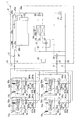
冷房運転モード(蒸発負荷大)の際、例えば、利用ユニット3a、3b、3c、3dの全てが冷房運転(すなわち、利用側熱交換器52a、52b、52c、52dの全てが冷媒の蒸発器として機能する運転)を行い、熱源側熱交換器24、25の両方が冷媒の放熱器として機能する際、空気調和装置1の冷媒回路10は、図4に示されるように構成される(冷媒の流れについては、図4の冷媒回路10に付された矢印を参照)。
<Cooling operation mode (high evaporation load)>
In the cooling operation mode (large evaporation load), for example, all of the usage units 3a, 3b, 3c, and 3d are in the cooling operation (that is, all of the usage side heat exchangers 52a, 52b, 52c, and 52d are refrigerant evaporators). When both the heat source side heat exchangers 24 and 25 function as refrigerant radiators, the refrigerant circuit 10 of the air conditioner 1 is configured as shown in FIG. (For the flow, see the arrow attached to the refrigerant circuit 10 in FIG. 4).

具体的には、熱源ユニット2においては、第1熱交切換機構22を放熱運転状態(図4の第1熱交切換機構22の実線で示された状態)に切り換え、第2熱交切換機構23を放熱運転状態(図4の第2熱交切換機構23の実線で示された状態)に切り換えることによって、熱源側熱交換器24、25の両方を冷媒の放熱器として機能させるようになっている。また、高低圧切換機構30を蒸発負荷主体運転状態(図4の高低圧切換機構30の実線で示された状態)に切り換えている。また、熱源側流量調節弁26、27は、開度調節され、レシーバ入口開閉弁28cは、開状態になっている。接続ユニット4a、4b、4c、4dにおいては、高圧ガス開閉弁66a、66b、66c、66d、及び、低圧ガス開閉弁67a、67b、67c、67dを開状態にすることによって、利用ユニット3a、3b、3c、3dの利用側熱交換器52a、52b、52c、52dの全てを冷媒の蒸発器として機能させるとともに、利用ユニット3a、3b、3c、3dの利用側熱交換器52a、52b、52c、52dの全てと熱源ユニット2の圧縮機21の吸入側とが高低圧ガス冷媒連絡管8及び低圧ガス冷媒連絡管9を介して接続された状態になっている。利用ユニット3a、3b、3c、3dにおいては、利用側流量調節弁51a、51b、51c、51dは、開度調節されている。   Specifically, in the heat source unit 2, the first heat exchange switching mechanism 22 is switched to the heat radiation operation state (the state indicated by the solid line of the first heat exchange switching mechanism 22 in FIG. 4), and the second heat exchange switching mechanism is selected. By switching 23 to the heat radiation operation state (the state indicated by the solid line of the second heat exchange switching mechanism 23 in FIG. 4), both the heat source side heat exchangers 24 and 25 function as a refrigerant radiator. ing. Further, the high / low pressure switching mechanism 30 is switched to the evaporative load main operation state (the state indicated by the solid line of the high / low pressure switching mechanism 30 in FIG. 4). Further, the opening amounts of the heat source side flow rate adjusting valves 26 and 27 are adjusted, and the receiver inlet opening / closing valve 28c is in an open state. In the connection units 4a, 4b, 4c and 4d, the use units 3a and 3b are opened by opening the high pressure gas on / off valves 66a, 66b, 66c and 66d and the low pressure gas on / off valves 67a, 67b, 67c and 67d. 3c, 3d use side heat exchangers 52a, 52b, 52c, 52d all function as refrigerant evaporators, and use units 3a, 3b, 3c, 3d use side heat exchangers 52a, 52b, 52c, All of 52d and the suction side of the compressor 21 of the heat source unit 2 are connected via the high and low pressure gas refrigerant communication pipe 8 and the low pressure gas refrigerant communication pipe 9. In the usage units 3a, 3b, 3c and 3d, the usage-side flow rate adjustment valves 51a, 51b, 51c and 51d are adjusted in opening.

このような冷媒回路10において、圧縮機21で圧縮され吐出された高圧のガス冷媒は、熱交切換機構22、23を通じて、熱源側熱交換器24、25の両方に送られる。そして、熱源側熱交換器24、25に送られた高圧のガス冷媒は、熱源側熱交換器24、25において、室外ファン34によって供給される熱源としての室外空気と熱交換を行うことによって放熱する。そして、熱源側熱交換器24、25において放熱した冷媒は、熱源側流量調節弁26、27において流量調節された後、合流して、入口逆止弁29a及びレシーバ入口開閉弁28cを通じて、レシーバ28に送られる。そして、レシーバ28に送られた冷媒は、レシーバ28内に一時的に溜められた後、出口逆止弁29c及び液側閉鎖弁31を通じて、液冷媒連絡管6に送られる。   In such a refrigerant circuit 10, the high-pressure gas refrigerant compressed and discharged by the compressor 21 is sent to both the heat source side heat exchangers 24 and 25 through the heat exchange switching mechanisms 22 and 23. The high-pressure gas refrigerant sent to the heat source side heat exchangers 24 and 25 radiates heat by exchanging heat with outdoor air as a heat source supplied by the outdoor fan 34 in the heat source side heat exchangers 24 and 25. To do. The refrigerant that has radiated heat in the heat source side heat exchangers 24 and 25 is adjusted in flow rate in the heat source side flow rate adjusting valves 26 and 27, and then merges and passes through the inlet check valve 29a and the receiver inlet on / off valve 28c. Sent to. The refrigerant sent to the receiver 28 is temporarily stored in the receiver 28, and then sent to the liquid refrigerant communication tube 6 through the outlet check valve 29 c and the liquid side closing valve 31.

そして、液冷媒連絡管6に送られた冷媒は、4つに分岐されて、各接続ユニット4a、4b、4c、4dの液接続管61a、61b、61c、61dに送られる。そして、液接続管61a、61b、61c、61dに送られた冷媒は、利用ユニット3a、3b、3c、3dの利用側流量調節弁51a、51b、51c、51dに送られる。   And the refrigerant | coolant sent to the liquid refrigerant communication pipe | tube 6 is branched into four, and is sent to the liquid connection pipes 61a, 61b, 61c, 61d of each connection unit 4a, 4b, 4c, 4d. The refrigerant sent to the liquid connection pipes 61a, 61b, 61c, 61d is sent to the usage-side flow rate adjustment valves 51a, 51b, 51c, 51d of the usage units 3a, 3b, 3c, 3d.

そして、利用側流量調節弁51a、51b、51c、51dに送られた冷媒は、利用側流量調節弁51a、51b、51c、51dにおいて流量調節された後、利用側熱交換器52a、52b、52c、52dにおいて、室内ファン53a、53b、53c、53dによって供給される室内空気と熱交換を行うことによって蒸発して低圧のガス冷媒となる。一方、室内空気は、冷却されて室内に供給されて、利用ユニット3a、3b、3c、3dの冷房運転が行われる。そして、低圧のガス冷媒は、接続ユニット4a、4b、4c、4dの合流ガス接続管65a、65b、65c、65dに送られる。   The refrigerant sent to the usage-side flow rate adjustment valves 51a, 51b, 51c, 51d is adjusted in flow rate at the usage-side flow rate adjustment valves 51a, 51b, 51c, 51d, and then used-side heat exchangers 52a, 52b, 52c. , 52d evaporates into a low-pressure gas refrigerant by exchanging heat with the indoor air supplied by the indoor fans 53a, 53b, 53c, 53d. On the other hand, the room air is cooled and supplied to the room, and the use units 3a, 3b, 3c, and 3d are cooled. Then, the low-pressure gas refrigerant is sent to the merged gas connection pipes 65a, 65b, 65c, and 65d of the connection units 4a, 4b, 4c, and 4d.

そして、合流ガス接続管65a、65b、65c、65dに送られた低圧のガス冷媒は、高圧ガス開閉弁66a、66b、66c、66d及び高圧ガス接続管63a、63b、63c、63dを通じて、高低圧ガス冷媒連絡管8に送られて合流するとともに、低圧ガス開閉弁67a、67b、67c、67d及び低圧ガス接続管64a、64b、64c、64dを通じて、低圧ガス冷媒連絡管9に送られて合流する。   The low-pressure gas refrigerant sent to the merged gas connection pipes 65a, 65b, 65c, 65d passes through the high-pressure gas on / off valves 66a, 66b, 66c, 66d and the high-pressure gas connection pipes 63a, 63b, 63c, 63d. The gas refrigerant communication pipe 8 is sent and merged, and the low pressure gas on / off valves 67a, 67b, 67c and 67d and the low pressure gas connection pipes 64a, 64b, 64c and 64d are sent to the low pressure gas refrigerant communication pipe 9 and merged. .

そして、ガス冷媒連絡管8、9に送られた低圧のガス冷媒は、ガス側閉鎖弁32、33及び高低圧切換機構30を通じて、圧縮機21の吸入側に戻される。   Then, the low-pressure gas refrigerant sent to the gas refrigerant communication pipes 8 and 9 is returned to the suction side of the compressor 21 through the gas-side stop valves 32 and 33 and the high-low pressure switching mechanism 30.

このようにして、冷房運転モード(蒸発負荷大)における動作が行われる。   In this way, the operation in the cooling operation mode (large evaporation load) is performed.

<冷房運転モード(蒸発負荷小)>
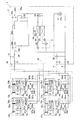
冷房運転モード(蒸発負荷小)、例えば、利用ユニット3aだけが冷房運転(すなわち、利用側熱交換器52aだけが冷媒の蒸発器として機能する運転)を行い、第1熱源側熱交換器24だけが冷媒の放熱器として機能する際、空気調和装置1の冷媒回路10は、図5に示されるように構成される(冷媒の流れについては、図5の冷媒回路10に付された矢印を参照)。
<Cooling operation mode (low evaporation load)>
In the cooling operation mode (low evaporation load), for example, only the use unit 3a performs the cooling operation (that is, only the use side heat exchanger 52a functions as a refrigerant evaporator), and only the first heat source side heat exchanger 24 is operated. 5 functions as a refrigerant radiator, the refrigerant circuit 10 of the air conditioner 1 is configured as shown in FIG. 5 (see the arrows attached to the refrigerant circuit 10 in FIG. 5 for the refrigerant flow). ).

具体的には、熱源ユニット2においては、第1熱交切換機構22を放熱運転状態(図5の第1熱交切換機構22の実線で示された状態)に切り換えることによって、第1熱源側熱交換器24だけを冷媒の放熱器として機能させるようになっている。また、高低圧切換機構30を蒸発負荷主体運転状態(図5の高低圧切換機構30の実線で示された状態)に切り換えている。また、第1熱源側流量調節弁26は、開度調節され、第2熱源側流量調節弁27は、閉状態になっており、レシーバ入口開閉弁28cは、開状態になっている。接続ユニット4a、4b、4c、4dにおいては、高圧ガス開閉弁66a、及び、低圧ガス開閉弁67aを開状態にし、かつ、高圧ガス開閉弁66b、66c、66d、及び、低圧ガス開閉弁67b、67c、67dを閉状態にすることによって、利用ユニット3aの利用側熱交換器52aだけを冷媒の蒸発器として機能させるとともに、利用ユニット3aの利用側熱交換器52aと熱源ユニット2の圧縮機21の吸入側とが高低圧ガス冷媒連絡管8及び低圧ガス冷媒連絡管9を介して接続された状態になっている。利用ユニット3aにおいては、利用側流量調節弁51aは、開度調節され、利用ユニット3b、3c、3dにおいては、利用側流量調節弁51b、51c、51dは、閉状態になっている。   Specifically, in the heat source unit 2, the first heat exchange switching mechanism 22 is switched to the heat radiation operation state (the state indicated by the solid line of the first heat exchange switching mechanism 22 in FIG. 5), thereby Only the heat exchanger 24 is made to function as a refrigerant radiator. Further, the high / low pressure switching mechanism 30 is switched to the evaporative load main operation state (the state shown by the solid line of the high / low pressure switching mechanism 30 in FIG. 5). Further, the opening degree of the first heat source side flow rate adjustment valve 26 is adjusted, the second heat source side flow rate adjustment valve 27 is in a closed state, and the receiver inlet on-off valve 28c is in an open state. In the connection units 4a, 4b, 4c and 4d, the high pressure gas on / off valve 66a and the low pressure gas on / off valve 67a are opened, and the high pressure gas on / off valves 66b, 66c and 66d and the low pressure gas on / off valve 67b By closing 67c and 67d, only the use side heat exchanger 52a of the use unit 3a functions as a refrigerant evaporator, and the use side heat exchanger 52a of the use unit 3a and the compressor 21 of the heat source unit 2 are used. Are connected via a high-low pressure gas refrigerant communication pipe 8 and a low-pressure gas refrigerant communication pipe 9. In the usage unit 3a, the usage-side flow rate adjustment valve 51a is adjusted in opening, and in the usage units 3b, 3c, and 3d, the usage-side flow rate adjustment valves 51b, 51c, and 51d are in a closed state.

このような冷媒回路10において、圧縮機21で圧縮され吐出された高圧のガス冷媒は、第1熱交切換機構22を通じて、第1熱源側熱交換器24だけに送られる。そして、第1熱源側熱交換器24に送られた高圧のガス冷媒は、第1熱源側熱交換器24において、室外ファン34によって供給される熱源としての室外空気と熱交換を行うことによって放熱する。そして、第1熱源側熱交換器24において放熱した冷媒は、第1熱源側流量調節弁26において流量調節された後、入口逆止弁29a及びレシーバ入口開閉弁28cを通じて、レシーバ28に送られる。そして、レシーバ28に送られた冷媒は、レシーバ28内に一時的に溜められた後、出口逆止弁29c及び液側閉鎖弁31を通じて、液冷媒連絡管6に送られる。   In such a refrigerant circuit 10, the high-pressure gas refrigerant compressed and discharged by the compressor 21 is sent only to the first heat source side heat exchanger 24 through the first heat exchange switching mechanism 22. The high-pressure gas refrigerant sent to the first heat source side heat exchanger 24 dissipates heat by exchanging heat with outdoor air as a heat source supplied by the outdoor fan 34 in the first heat source side heat exchanger 24. To do. The refrigerant that has radiated heat in the first heat source side heat exchanger 24 is adjusted in flow rate in the first heat source side flow rate adjustment valve 26 and then sent to the receiver 28 through the inlet check valve 29a and the receiver inlet opening / closing valve 28c. The refrigerant sent to the receiver 28 is temporarily stored in the receiver 28, and then sent to the liquid refrigerant communication tube 6 through the outlet check valve 29 c and the liquid side closing valve 31.

そして、液冷媒連絡管6に送られた冷媒は、接続ユニット4aの液接続管61aだけに送られる。そして、接続ユニット4aの液接続管61aに送られた冷媒は、利用ユニット3aの利用側流量調節弁51aに送られる。   The refrigerant sent to the liquid refrigerant communication pipe 6 is sent only to the liquid connection pipe 61a of the connection unit 4a. And the refrigerant | coolant sent to the liquid connection pipe | tube 61a of the connection unit 4a is sent to the utilization side flow control valve 51a of the utilization unit 3a.

そして、利用側流量調節弁51aに送られた冷媒は、利用側流量調節弁51aにおいて流量調節された後、利用側熱交換器52aにおいて、室内ファン53aによって供給される室内空気と熱交換を行うことによって蒸発して低圧のガス冷媒となる。一方、室内空気は、冷却されて室内に供給されて、利用ユニット3aだけの冷房運転が行われる。そして、低圧のガス冷媒は、接続ユニット4aの合流ガス接続管65aに送られる。   The refrigerant sent to the usage-side flow rate adjustment valve 51a is subjected to heat exchange with the indoor air supplied by the indoor fan 53a in the usage-side heat exchanger 52a after the flow rate is adjusted in the usage-side flow rate adjustment valve 51a. As a result, it evaporates into a low-pressure gas refrigerant. On the other hand, the room air is cooled and supplied to the room, and only the use unit 3a is cooled. Then, the low-pressure gas refrigerant is sent to the merged gas connection pipe 65a of the connection unit 4a.

そして、合流ガス接続管65aに送られた低圧のガス冷媒は、高圧ガス開閉弁66a及び高圧ガス接続管63aを通じて、高低圧ガス冷媒連絡管8に送られるとともに、低圧ガス開閉弁67a及び低圧ガス接続管64aを通じて、低圧ガス冷媒連絡管9に送られる。   The low-pressure gas refrigerant sent to the merged gas connection pipe 65a is sent to the high-low pressure gas refrigerant communication pipe 8 through the high-pressure gas on-off valve 66a and the high-pressure gas connection pipe 63a, and at the same time the low-pressure gas on-off valve 67a and low-pressure gas. It is sent to the low-pressure gas refrigerant communication pipe 9 through the connection pipe 64a.

そして、ガス冷媒連絡管8、9に送られた低圧のガス冷媒は、ガス側閉鎖弁32、33及び高低圧切換機構30を通じて、圧縮機21の吸入側に戻される。   Then, the low-pressure gas refrigerant sent to the gas refrigerant communication pipes 8 and 9 is returned to the suction side of the compressor 21 through the gas-side stop valves 32 and 33 and the high-low pressure switching mechanism 30.

このようにして、冷房運転モード(蒸発負荷小)における動作が行われる。   In this way, the operation in the cooling operation mode (low evaporation load) is performed.

<暖房運転モード(放熱負荷大)>
暖房運転モード(放熱負荷大)の際、例えば、利用ユニット3a、3b、3c、3dの全てが暖房運転(すなわち、利用側熱交換器52a、52b、52c、52dの全てが冷媒の放熱器として機能する運転)を行い、熱源側熱交換器24、25の両方が冷媒の蒸発器として機能する際、空気調和装置1の冷媒回路10は、図6に示されるように構成される(冷媒の流れについては、図6の冷媒回路10に付された矢印を参照)。
<Heating operation mode (high heat radiation load)>
In the heating operation mode (large heat radiation load), for example, all of the usage units 3a, 3b, 3c, and 3d are in the heating operation (that is, all of the usage-side heat exchangers 52a, 52b, 52c, and 52d are refrigerant radiators). When both the heat source side heat exchangers 24 and 25 function as refrigerant evaporators, the refrigerant circuit 10 of the air conditioner 1 is configured as shown in FIG. (For the flow, see the arrow attached to the refrigerant circuit 10 in FIG. 6).

具体的には、熱源ユニット2においては、第1熱交切換機構22を蒸発運転状態(図6の第1熱交切換機構22の破線で示された状態)に切り換え、第2熱交切換機構23を蒸発運転状態(図6の第2熱交切換機構23の破線で示された状態)に切り換えることによって、熱源側熱交換器24、25の両方を冷媒の蒸発器として機能させるようになっている。また、高低圧切換機構30を放熱負荷主体運転状態(図6の高低圧切換機構30の破線で示された状態)に切り換えている。また、熱源側流量調節弁26、27は、開度調節され、レシーバ入口開閉弁28cは、開状態になっている。接続ユニット4a、4b、4c、4dにおいては、高圧ガス開閉弁66a、66b、66c、66dを開状態にし、低圧ガス開閉弁67a、67b、67c、67dを閉状態にすることによって、利用ユニット3a、3b、3c、3dの利用側熱交換器52a、52b、52c、52dの全てを冷媒の放熱器として機能させるとともに、利用ユニット3a、3b、3c、3dの利用側熱交換器52a、52b、52c、52dの全てと熱源ユニット2の圧縮機21の吐出側とが高低圧ガス冷媒連絡管8を介して接続された状態になっている。利用ユニット3a、3b、3c、3dにおいては、利用側流量調節弁51a、51b、51c、51dは、開度調節されている。   Specifically, in the heat source unit 2, the first heat exchange switching mechanism 22 is switched to the evaporation operation state (the state indicated by the broken line of the first heat exchange switching mechanism 22 in FIG. 6), and the second heat exchange switching mechanism is selected. 23 is switched to the evaporation operation state (the state indicated by the broken line of the second heat exchange switching mechanism 23 in FIG. 6), so that both the heat source side heat exchangers 24 and 25 function as a refrigerant evaporator. ing. Further, the high / low pressure switching mechanism 30 is switched to the heat radiation load main operation state (the state indicated by the broken line of the high / low pressure switching mechanism 30 in FIG. 6). Further, the opening amounts of the heat source side flow rate adjusting valves 26 and 27 are adjusted, and the receiver inlet opening / closing valve 28c is in an open state. In the connection units 4a, 4b, 4c, and 4d, the high pressure gas on / off valves 66a, 66b, 66c, and 66d are opened, and the low pressure gas on / off valves 67a, 67b, 67c, and 67d are closed, thereby using the use unit 3a. 3b, 3c, 3d use side heat exchangers 52a, 52b, 52c, 52d all function as refrigerant radiators, and use units 3a, 3b, 3c, 3d use side heat exchangers 52a, 52b, All of 52c and 52d and the discharge side of the compressor 21 of the heat source unit 2 are connected via the high and low pressure gas refrigerant communication pipe 8. In the usage units 3a, 3b, 3c and 3d, the usage-side flow rate adjustment valves 51a, 51b, 51c and 51d are adjusted in opening.

このような冷媒回路10において、圧縮機21で圧縮され吐出された高圧のガス冷媒は、高低圧切換機構30及び高低圧ガス側閉鎖弁32を通じて、高低圧ガス冷媒連絡管8に送られる。   In such a refrigerant circuit 10, the high-pressure gas refrigerant compressed and discharged by the compressor 21 is sent to the high / low pressure gas refrigerant communication pipe 8 through the high / low pressure switching mechanism 30 and the high / low pressure gas side closing valve 32.

そして、高低圧ガス冷媒連絡管8に送られた高圧のガス冷媒は、4つに分岐されて、各接続ユニット4a、4b、4c、4dの高圧ガス接続管63a、63b、63c、63dに送られる。高圧ガス接続管63a、63b、63c、63dに送られた高圧のガス冷媒は、高圧ガス開閉弁66a、66b、66c、66d及び合流ガス接続管65a、65b、65c、65dを通じて、利用ユニット3a、3b、3c、3dの利用側熱交換器52a、52b、52c、52dに送られる。   The high-pressure gas refrigerant sent to the high-low pressure gas refrigerant communication pipe 8 is branched into four and sent to the high-pressure gas connection pipes 63a, 63b, 63c, 63d of the connection units 4a, 4b, 4c, 4d. It is done. The high-pressure gas refrigerant sent to the high-pressure gas connection pipes 63a, 63b, 63c, 63d passes through the high-pressure gas on / off valves 66a, 66b, 66c, 66d and the merged gas connection pipes 65a, 65b, 65c, 65d. It is sent to the use side heat exchangers 52a, 52b, 52c, 52d of 3b, 3c, 3d.

そして、利用側熱交換器52a、52b、52c、52dに送られた高圧のガス冷媒は、利用側熱交換器52a、52b、52c、52dにおいて、室内ファン53a、53b、53c、53dによって供給される室内空気と熱交換を行うことによって放熱する。一方、室内空気は、加熱されて室内に供給されて、利用ユニット3a、3b、3c、3dの暖房運転が行われる。利用側熱交換器52a、52b、52c、52dにおいて放熱した冷媒は、利用側流量調節弁51a、51b、51c、51dにおいて流量調節された後、接続ユニット4a、4b、4c、4dの液接続管61a、61b、61c、61dに送られる。   The high-pressure gas refrigerant sent to the use side heat exchangers 52a, 52b, 52c, and 52d is supplied by the indoor fans 53a, 53b, 53c, and 53d in the use side heat exchangers 52a, 52b, 52c, and 52d. Heat is dissipated by exchanging heat with indoor air. On the other hand, indoor air is heated and supplied indoors, and heating operation of utilization unit 3a, 3b, 3c, 3d is performed. The refrigerant radiated in the use side heat exchangers 52a, 52b, 52c, 52d is adjusted in flow rate in the use side flow rate adjusting valves 51a, 51b, 51c, 51d, and then the liquid connection pipes of the connection units 4a, 4b, 4c, 4d. 61a, 61b, 61c and 61d.

そして、液接続管61a、61b、61c、61dに送られた冷媒は、液冷媒連絡管6に送られて合流する。   Then, the refrigerant sent to the liquid connection pipes 61a, 61b, 61c, 61d is sent to the liquid refrigerant communication pipe 6 and merges.

そして、液冷媒連絡管6に送られた冷媒は、液側閉鎖弁31、入口逆止弁29b及びレシーバ入口開閉弁28cを通じて、レシーバ28に送られる。レシーバ28に送られた冷媒は、レシーバ28内に一時的に溜められた後、出口逆止弁29dを通じて、熱源側流量調節弁26、27の両方に送られる。そして、熱源側流量調節弁26、27に送られた冷媒は、熱源側流量調節弁26、27において流量調節された後、熱源側熱交換器24、25において、室外ファン34によって供給される室外空気と熱交換を行うことによって蒸発して低圧のガス冷媒になり、熱交切換機構22、23に送られる。そして、熱交切換機構22、23に送られた低圧のガス冷媒は、合流して、圧縮機21の吸入側に戻される。   Then, the refrigerant sent to the liquid refrigerant communication tube 6 is sent to the receiver 28 through the liquid side closing valve 31, the inlet check valve 29b, and the receiver inlet opening / closing valve 28c. The refrigerant sent to the receiver 28 is temporarily stored in the receiver 28 and then sent to both the heat source side flow rate adjustment valves 26 and 27 through the outlet check valve 29d. The refrigerant sent to the heat source side flow rate adjustment valves 26, 27 is adjusted in flow rate in the heat source side flow rate adjustment valves 26, 27, and then is supplied to the outdoor source 34 by the outdoor fan 34 in the heat source side heat exchangers 24, 25. By evaporating with air, it evaporates into a low-pressure gas refrigerant and is sent to the heat exchange switching mechanisms 22 and 23. The low-pressure gas refrigerant sent to the heat exchange switching mechanisms 22 and 23 merges and returns to the suction side of the compressor 21.

このようにして、暖房運転モード(放熱負荷大)における動作が行われる。   In this way, the operation in the heating operation mode (large heat radiation load) is performed.

<暖房運転モード(放熱負荷小)>
暖房運転モード(放熱負荷小)、例えば、利用ユニット3aだけが暖房運転(すなわち、利用側熱交換器52aだけが冷媒の放熱器として機能する運転)を行い、第1熱源側熱交換器24だけが冷媒の蒸発器として機能する際、空気調和装置1の冷媒回路10は、図7に示されるように構成される(冷媒の流れについては、図7の冷媒回路10に付された矢印を参照)。
<Heating operation mode (low heat radiation load)>
In the heating operation mode (small heat radiation load), for example, only the usage unit 3a performs the heating operation (that is, only the usage-side heat exchanger 52a functions as a refrigerant radiator), and only the first heat source-side heat exchanger 24 is operated. 7 functions as a refrigerant evaporator, the refrigerant circuit 10 of the air conditioner 1 is configured as shown in FIG. 7 (see the arrows attached to the refrigerant circuit 10 in FIG. 7 for the refrigerant flow). ).

具体的には、熱源ユニット2においては、第1熱交切換機構22を蒸発運転状態(図7の第1熱交切換機構22の破線で示された状態)に切り換えることによって、第1熱源側熱交換器24だけを冷媒の蒸発器として機能させるようになっている。また、高低圧切換機構30を放熱負荷主体運転状態(図7の高低圧切換機構30の破線で示された状態)に切り換えている。また、第1熱源側流量調節弁26は、開度調節され、第2熱源側流量調節弁27は、閉状態になっており、レシーバ入口開閉弁28cは、開状態になっている。接続ユニット4a、4b、4c、4dにおいては、高圧ガス開閉弁66aを開状態にし、高圧ガス開閉弁66b、66c、66d、及び、低圧ガス開閉弁67a、67b、67c、67dを閉状態にすることによって、利用ユニット3aの利用側熱交換器52aだけを冷媒の放熱器として機能させるとともに、利用ユニット3aの利用側熱交換器52aと熱源ユニット2の圧縮機21の吐出側とが高低圧ガス冷媒連絡管8を介して接続された状態になっている。利用ユニット3aにおいては、利用側流量調節弁51aは、開度調節され、利用ユニット3b、3c、3dにおいては、利用側流量調節弁51b、51c、51dは、閉状態になっている。   Specifically, in the heat source unit 2, the first heat source switching mechanism 22 is switched to the evaporation operation state (the state indicated by the broken line of the first heat exchange switching mechanism 22 in FIG. 7), thereby Only the heat exchanger 24 functions as a refrigerant evaporator. Further, the high / low pressure switching mechanism 30 is switched to the heat radiation load main operation state (the state indicated by the broken line of the high / low pressure switching mechanism 30 in FIG. 7). Further, the opening degree of the first heat source side flow rate adjustment valve 26 is adjusted, the second heat source side flow rate adjustment valve 27 is in a closed state, and the receiver inlet on-off valve 28c is in an open state. In the connection units 4a, 4b, 4c and 4d, the high pressure gas on / off valve 66a is opened, and the high pressure gas on / off valves 66b, 66c and 66d and the low pressure gas on / off valves 67a, 67b, 67c and 67d are closed. As a result, only the utilization side heat exchanger 52a of the utilization unit 3a functions as a refrigerant radiator, and the utilization side heat exchanger 52a of the utilization unit 3a and the discharge side of the compressor 21 of the heat source unit 2 have high and low pressure gas. It is in a connected state via the refrigerant communication pipe 8. In the usage unit 3a, the usage-side flow rate adjustment valve 51a is adjusted in opening, and in the usage units 3b, 3c, and 3d, the usage-side flow rate adjustment valves 51b, 51c, and 51d are in a closed state.

このような冷媒回路10において、圧縮機21で圧縮され吐出された高圧のガス冷媒は、高低圧切換機構30及び高低圧ガス側閉鎖弁32を通じて、高低圧ガス冷媒連絡管8に送られる。   In such a refrigerant circuit 10, the high-pressure gas refrigerant compressed and discharged by the compressor 21 is sent to the high / low pressure gas refrigerant communication pipe 8 through the high / low pressure switching mechanism 30 and the high / low pressure gas side closing valve 32.

そして、高低圧ガス冷媒連絡管8に送られた高圧のガス冷媒は、接続ユニット4aの高圧ガス接続管63aだけに送られる。高圧ガス接続管63aに送られた高圧のガス冷媒は、高圧ガス開閉弁66a及び合流ガス接続管65aを通じて、利用ユニット3aの利用側熱交換器52aに送られる。   The high-pressure gas refrigerant sent to the high-low pressure gas refrigerant communication pipe 8 is sent only to the high-pressure gas connection pipe 63a of the connection unit 4a. The high-pressure gas refrigerant sent to the high-pressure gas connection pipe 63a is sent to the use-side heat exchanger 52a of the use unit 3a through the high-pressure gas on-off valve 66a and the merged gas connection pipe 65a.

そして、利用側熱交換器52aに送られた高圧のガス冷媒は、利用側熱交換器52aにおいて、室内ファン53aによって供給される室内空気と熱交換を行うことによって放熱する。一方、室内空気は、加熱されて室内に供給されて、利用ユニット3aだけの暖房運転が行われる。利用側熱交換器52aにおいて放熱した冷媒は、利用側流量調節弁51aにおいて流量調節された後、接続ユニット4aの液接続管61aに送られる。   The high-pressure gas refrigerant sent to the usage-side heat exchanger 52a dissipates heat by exchanging heat with indoor air supplied by the indoor fan 53a in the usage-side heat exchanger 52a. On the other hand, indoor air is heated and supplied indoors, and only the utilization unit 3a is heated. The refrigerant radiated in the use side heat exchanger 52a is sent to the liquid connection pipe 61a of the connection unit 4a after the flow rate is adjusted in the use side flow rate adjustment valve 51a.

そして、液接続管61aに送られた冷媒は、液冷媒連絡管6に送られる。   The refrigerant sent to the liquid connection pipe 61 a is sent to the liquid refrigerant communication pipe 6.

そして、液冷媒連絡管6に送られた冷媒は、液側閉鎖弁31、入口逆止弁29b及びレシーバ入口開閉弁28cを通じて、レシーバ28に送られる。レシーバ28に送られた冷媒は、レシーバ28内に一時的に溜められた後、出口逆止弁29dを通じて、第1熱源側流量調節弁26だけに送られる。そして、第1熱源側流量調節弁26に送られた冷媒は、第1熱源側流量調節弁26において流量調節された後、第1熱源側熱交換器24において、室外ファン34によって供給される室外空気と熱交換を行うことによって蒸発して低圧のガス冷媒になり、第1熱交切換機構22に送られる。そして、第1熱交切換機構22に送られた低圧のガス冷媒は、圧縮機21の吸入側に戻される。   Then, the refrigerant sent to the liquid refrigerant communication tube 6 is sent to the receiver 28 through the liquid side closing valve 31, the inlet check valve 29b, and the receiver inlet opening / closing valve 28c. The refrigerant sent to the receiver 28 is temporarily stored in the receiver 28 and then sent only to the first heat source side flow rate adjustment valve 26 through the outlet check valve 29d. The refrigerant sent to the first heat source side flow rate adjustment valve 26 is adjusted in flow rate in the first heat source side flow rate adjustment valve 26, and then is supplied to the outdoor side supplied by the outdoor fan 34 in the first heat source side heat exchanger 24. By evaporating with air, it evaporates into a low-pressure gas refrigerant and is sent to the first heat exchange switching mechanism 22. Then, the low-pressure gas refrigerant sent to the first heat exchange switching mechanism 22 is returned to the suction side of the compressor 21.

このようにして、暖房運転モード(放熱負荷小)における動作が行われる。   Thus, the operation in the heating operation mode (small heat radiation load) is performed.

<冷暖同時運転モード(蒸発負荷主体)>
冷暖同時運転モード(蒸発負荷主体)、例えば、利用ユニット3a、3b、3cが冷房運転し、かつ、利用ユニット3dが暖房運転し(すなわち、利用側熱交換器52a、52b、52cが冷媒の蒸発器として機能し、かつ、利用側熱交換器52dが冷媒の放熱器として機能する運転)を行い、第1熱源側熱交換器24だけが冷媒の放熱器として機能する際、空気調和装置1の冷媒回路10は、図8に示されるように構成される(冷媒の流れについては、図8の冷媒回路10に付された矢印を参照)。
<Cooling and heating simultaneous operation mode (evaporation load mainly)>
Cooling and heating simultaneous operation mode (evaporation load main), for example, the usage units 3a, 3b, and 3c are in cooling operation, and the usage unit 3d is in heating operation (that is, the usage-side heat exchangers 52a, 52b, and 52c are evaporated of refrigerant) When the first heat source side heat exchanger 24 functions as a refrigerant radiator, the air conditioner 1 of the air conditioner 1 is operated. The refrigerant circuit 10 is configured as shown in FIG. 8 (refer to the arrows attached to the refrigerant circuit 10 in FIG. 8 for the refrigerant flow).

具体的には、熱源ユニット2においては、第1熱交切換機構22を放熱運転状態(図8の第1熱交切換機構22の実線で示された状態)に切り換えることによって、第1熱源側熱交換器24だけを冷媒の放熱器として機能させるようになっている。また、高低圧切換機構30を放熱負荷主体運転状態(図8の高低圧切換機構30の破線で示された状態)に切り換えている。また、第1熱源側流量調節弁26は、開度調節され、第2熱源側流量調節弁27は、閉状態になっており、レシーバ入口開閉弁28cは、開状態になっている。接続ユニット4a、4b、4c、4dにおいては、高圧ガス開閉弁66d、及び、低圧ガス開閉弁67a、67b、67cを開状態にし、かつ、高圧ガス開閉弁66a、66b、66c、及び、低圧ガス開閉弁67dを閉状態にすることによって、利用ユニット3a、3b、3cの利用側熱交換器52a、52b、52cを冷媒の蒸発器として機能させ、かつ、利用ユニット3dの利用側熱交換器52dを冷媒の放熱器として機能させるとともに、利用ユニット3a、3b、3cの利用側熱交換器52a、52b、52cと熱源ユニット2の圧縮機21の吸入側とが低圧ガス冷媒連絡管9を介して接続された状態になり、かつ、利用ユニット3dの利用側熱交換器52dと熱源ユニット2の圧縮機21の吐出側とが高低圧ガス冷媒連絡管8を介して接続された状態になっている。利用ユニット3a、3b、3c、3dにおいては、利用側流量調節弁51a、51b、51c、51dは、開度調節されている。   Specifically, in the heat source unit 2, the first heat exchange switching mechanism 22 is switched to the heat dissipation operation state (the state indicated by the solid line of the first heat exchange switching mechanism 22 in FIG. 8), thereby Only the heat exchanger 24 is made to function as a refrigerant radiator. Further, the high / low pressure switching mechanism 30 is switched to the heat radiation load main operation state (the state indicated by the broken line of the high / low pressure switching mechanism 30 in FIG. 8). Further, the opening degree of the first heat source side flow rate adjustment valve 26 is adjusted, the second heat source side flow rate adjustment valve 27 is in a closed state, and the receiver inlet on-off valve 28c is in an open state. In the connection units 4a, 4b, 4c, and 4d, the high-pressure gas on-off valve 66d and the low-pressure gas on-off valves 67a, 67b, and 67c are opened, and the high-pressure gas on-off valves 66a, 66b, 66c, and the low-pressure gas By closing the on-off valve 67d, the use side heat exchangers 52a, 52b, 52c of the use units 3a, 3b, 3c function as a refrigerant evaporator, and the use side heat exchanger 52d of the use unit 3d. Through the low-pressure gas refrigerant communication pipe 9 between the utilization side heat exchangers 52a, 52b, 52c of the utilization units 3a, 3b, 3c and the suction side of the compressor 21 of the heat source unit 2. The use side heat exchanger 52d of the use unit 3d and the discharge side of the compressor 21 of the heat source unit 2 are connected to the high / low pressure gas refrigerant communication pipe 8 in a connected state. To have become the connected state. In the usage units 3a, 3b, 3c and 3d, the usage-side flow rate adjustment valves 51a, 51b, 51c and 51d are adjusted in opening.

このような冷媒回路10において、圧縮機21で圧縮され吐出された高圧のガス冷媒は、その一部が、高低圧切換機構30及び高低圧ガス側閉鎖弁32を通じて、高低圧ガス冷媒連絡管8に送られ、残りが、第1熱交切換機構22を通じて、第1熱源側熱交換器24に送られる。   In such a refrigerant circuit 10, a part of the high-pressure gas refrigerant compressed and discharged by the compressor 21 passes through the high / low pressure switching mechanism 30 and the high / low pressure gas side shut-off valve 32. The remainder is sent to the first heat source side heat exchanger 24 through the first heat exchange switching mechanism 22.

そして、高低圧ガス冷媒連絡管8に送られた高圧のガス冷媒は、接続ユニット4dの高圧ガス接続管63dに送られる。高圧ガス接続管63dに送られた高圧のガス冷媒は、高圧ガス開閉弁66d及び合流ガス接続管65dを通じて、利用ユニット3dの利用側熱交換器52dに送られる。   Then, the high-pressure gas refrigerant sent to the high-low pressure gas refrigerant communication pipe 8 is sent to the high-pressure gas connection pipe 63d of the connection unit 4d. The high-pressure gas refrigerant sent to the high-pressure gas connection pipe 63d is sent to the use-side heat exchanger 52d of the use unit 3d through the high-pressure gas on-off valve 66d and the merged gas connection pipe 65d.

そして、利用側熱交換器52dに送られた高圧のガス冷媒は、利用側熱交換器52dにおいて、室内ファン53dによって供給される室内空気と熱交換を行うことによって放熱する。一方、室内空気は、加熱されて室内に供給されて、利用ユニット3dの暖房運転が行われる。利用側熱交換器52dにおいて放熱した冷媒は、利用側流量調節弁51dにおいて流量調節された後、接続ユニット4dの液接続管61dに送られる。   The high-pressure gas refrigerant sent to the use side heat exchanger 52d dissipates heat by exchanging heat with the indoor air supplied by the indoor fan 53d in the use side heat exchanger 52d. On the other hand, the indoor air is heated and supplied indoors, and the heating operation of the utilization unit 3d is performed. The refrigerant that has radiated heat in the use side heat exchanger 52d is sent to the liquid connection pipe 61d of the connection unit 4d after the flow rate is adjusted in the use side flow rate adjustment valve 51d.

また、第1熱源側熱交換器24に送られた高圧のガス冷媒は、第1熱源側熱交換器24において、室外ファン34によって供給される熱源としての室外空気と熱交換を行うことによって放熱する。そして、第1熱源側熱交換器24において放熱した冷媒は、第1熱源側流量調節弁26において流量調節された後、入口逆止弁29a及びレシーバ入口開閉弁28cを通じて、レシーバ28に送られる。そして、レシーバ28に送られた冷媒は、レシーバ28内に一時的に溜められた後、出口逆止弁29c及び液側閉鎖弁31を通じて、液冷媒連絡管6に送られる。   The high-pressure gas refrigerant sent to the first heat source side heat exchanger 24 dissipates heat by exchanging heat with outdoor air as a heat source supplied by the outdoor fan 34 in the first heat source side heat exchanger 24. To do. The refrigerant that has radiated heat in the first heat source side heat exchanger 24 is adjusted in flow rate in the first heat source side flow rate adjustment valve 26 and then sent to the receiver 28 through the inlet check valve 29a and the receiver inlet opening / closing valve 28c. The refrigerant sent to the receiver 28 is temporarily stored in the receiver 28, and then sent to the liquid refrigerant communication tube 6 through the outlet check valve 29 c and the liquid side closing valve 31.

そして、利用側熱交換器52dにおいて放熱して液接続管61dに送られた冷媒は、液冷媒連絡管6に送られて、第1熱源側熱交換器24において放熱して液冷媒連絡管6に送られた冷媒と合流する。   The refrigerant radiated in the use side heat exchanger 52d and sent to the liquid connection pipe 61d is sent to the liquid refrigerant communication pipe 6 and radiated in the first heat source side heat exchanger 24 to be radiated. It merges with the refrigerant sent to.

そして、液冷媒連絡管6において合流した冷媒は、3つに分岐されて、各接続ユニット4a、4b、4cの液接続管61a、61b、61cに送られる。そして、液接続管61a、61b、61cに送られた冷媒は、利用ユニット3a、3b、3cの利用側流量調節弁51a、51b、51cに送られる。   And the refrigerant | coolant merged in the liquid refrigerant connection pipe | tube 6 is branched into three, and is sent to the liquid connection pipes 61a, 61b, 61c of each connection unit 4a, 4b, 4c. Then, the refrigerant sent to the liquid connection pipes 61a, 61b, 61c is sent to the use side flow rate adjusting valves 51a, 51b, 51c of the use units 3a, 3b, 3c.

そして、利用側流量調節弁51a、51b、51cに送られた冷媒は、利用側流量調節弁51a、51b、51cにおいて流量調節された後、利用側熱交換器52a、52b、52cにおいて、室内ファン53a、53b、53cによって供給される室内空気と熱交換を行うことによって蒸発して低圧のガス冷媒となる。一方、室内空気は、冷却されて室内に供給されて、利用ユニット3a、3b、3cの冷房運転が行われる。そして、低圧のガス冷媒は、接続ユニット4a、4b、4cの合流ガス接続管65a、65b、65cに送られる。   The refrigerant sent to the usage-side flow rate adjustment valves 51a, 51b, 51c is adjusted in flow rate at the usage-side flow rate adjustment valves 51a, 51b, 51c, and then the indoor fan in the usage-side heat exchangers 52a, 52b, 52c. By exchanging heat with the indoor air supplied by 53a, 53b, 53c, it evaporates and becomes a low-pressure gas refrigerant. On the other hand, the room air is cooled and supplied to the room, and the use units 3a, 3b, and 3c are cooled. Then, the low-pressure gas refrigerant is sent to the merged gas connection pipes 65a, 65b, and 65c of the connection units 4a, 4b, and 4c.

そして、合流ガス接続管65a、65b、65cに送られた低圧のガス冷媒は、低圧ガス開閉弁67a、67b、67c及び低圧ガス接続管64a、64b、64cを通じて、低圧ガス冷媒連絡管9に送られて合流する。   The low-pressure gas refrigerant sent to the merged gas connection pipes 65a, 65b, 65c is sent to the low-pressure gas refrigerant communication pipe 9 through the low-pressure gas on-off valves 67a, 67b, 67c and the low-pressure gas connection pipes 64a, 64b, 64c. Be merged.

そして、低圧ガス冷媒連絡管9に送られた低圧のガス冷媒は、ガス側閉鎖弁33を通じて、圧縮機21の吸入側に戻される。   Then, the low-pressure gas refrigerant sent to the low-pressure gas refrigerant communication pipe 9 is returned to the suction side of the compressor 21 through the gas-side closing valve 33.

このようにして、冷暖同時運転モード(蒸発負荷主体)における動作が行われる。そして、冷暖同時運転モード(蒸発負荷主体)では、上記のように、冷媒の放熱器として機能する利用側熱交換器52dから冷媒の蒸発器として機能する利用側熱交換器52a、52b、52cに冷媒を送ることで利用側熱交換器52a、52b、52c、52d間において熱回収が行われるようになっている。   Thus, the operation in the cooling and heating simultaneous operation mode (evaporation load main body) is performed. In the cooling / heating simultaneous operation mode (mainly evaporation load), as described above, the use side heat exchangers 52a, 52b, 52c functioning as the refrigerant evaporator are changed from the use side heat exchanger 52d functioning as the refrigerant radiator. Heat is recovered between the use-side heat exchangers 52a, 52b, 52c, and 52d by sending the refrigerant.

<冷暖同時運転モード(放熱負荷主体)>
冷暖同時運転モード(放熱負荷主体)、例えば、利用ユニット3a、3b、3cが暖房運転し、かつ、利用ユニット3dが冷房運転し(すなわち、利用側熱交換器52a、52b、52cが冷媒の放熱器として機能し、かつ、利用側熱交換器52dが冷媒の蒸発器として機能する運転)を行い、第1熱源側熱交換器24だけが冷媒の蒸発器として機能する際、空気調和装置1の冷媒回路10は、図9に示されるように構成される(冷媒の流れについては、図9の冷媒回路10に付された矢印を参照)。
<Cooling and heating simultaneous operation mode (heat radiation load mainly)>
Simultaneous cooling and heating operation mode (mainly heat radiation load), for example, the usage units 3a, 3b, and 3c perform heating operation, and the usage unit 3d performs cooling operation (that is, the usage-side heat exchangers 52a, 52b, and 52c release heat from the refrigerant). When the use side heat exchanger 52d functions as a refrigerant evaporator and only the first heat source side heat exchanger 24 functions as a refrigerant evaporator, the air conditioner 1 The refrigerant circuit 10 is configured as shown in FIG. 9 (refer to the arrows attached to the refrigerant circuit 10 in FIG. 9 for the refrigerant flow).

具体的には、熱源ユニット2においては、第1熱交切換機構22を蒸発運転状態(図9の第1熱交切換機構22の破線で示された状態)に切り換えることによって、第1熱源側熱交換器24だけを冷媒の蒸発器として機能させるようになっている。また、高低圧切換機構30を放熱負荷主体運転状態(図9の高低圧切換機構30の破線で示された状態)に切り換えている。また、第1熱源側流量調節弁26は、開度調節され、第2熱源側流量調節弁27は、閉状態になっており、レシーバ入口開閉弁28cは、開状態になっている。接続ユニット4a、4b、4c、4dにおいては、高圧ガス開閉弁66a、66b、66c、及び、低圧ガス開閉弁67dを開状態にし、かつ、高圧ガス開閉弁66d、及び、低圧ガス開閉弁67a、67b、67cを閉状態にすることによって、利用ユニット3a、3b、3cの利用側熱交換器52a、52b、52cを冷媒の放熱器として機能させ、かつ、利用ユニット3dの利用側熱交換器52dを冷媒の蒸発器として機能させるとともに、利用ユニット3dの利用側熱交換器52dと熱源ユニット2の圧縮機21の吸入側とが低圧ガス冷媒連絡管9を介して接続された状態になり、かつ、利用ユニット3a、3b、3cの利用側熱交換器52a、52b、52cと熱源ユニット2の圧縮機21の吐出側とが高低圧ガス冷媒連絡管8を介して接続された状態になっている。利用ユニット3a、3b、3c、3dにおいては、利用側流量調節弁51a、51b、51c、51dは、開度調節されている。   Specifically, in the heat source unit 2, by switching the first heat exchange switching mechanism 22 to the evaporation operation state (the state indicated by the broken line of the first heat exchange switching mechanism 22 in FIG. 9), the first heat source switching mechanism 22 Only the heat exchanger 24 functions as a refrigerant evaporator. Further, the high / low pressure switching mechanism 30 is switched to the heat radiation load main operation state (the state indicated by the broken line of the high / low pressure switching mechanism 30 in FIG. 9). Further, the opening degree of the first heat source side flow rate adjustment valve 26 is adjusted, the second heat source side flow rate adjustment valve 27 is in a closed state, and the receiver inlet on-off valve 28c is in an open state. In the connection units 4a, 4b, 4c and 4d, the high pressure gas on / off valves 66a, 66b and 66c and the low pressure gas on / off valve 67d are opened, and the high pressure gas on / off valve 66d and the low pressure gas on / off valve 67a, By closing 67b and 67c, the utilization side heat exchangers 52a, 52b and 52c of the utilization units 3a, 3b and 3c function as refrigerant radiators, and the utilization side heat exchanger 52d of the utilization unit 3d. As a refrigerant evaporator, the utilization side heat exchanger 52d of the utilization unit 3d and the suction side of the compressor 21 of the heat source unit 2 are connected via the low-pressure gas refrigerant communication pipe 9, and The use side heat exchangers 52a, 52b, 52c of the use units 3a, 3b, 3c and the discharge side of the compressor 21 of the heat source unit 2 connect the high / low pressure gas refrigerant communication pipe 8. To have become the connected state. In the usage units 3a, 3b, 3c and 3d, the usage-side flow rate adjustment valves 51a, 51b, 51c and 51d are adjusted in opening.

このような冷媒回路10において、圧縮機21で圧縮され吐出された高圧のガス冷媒は、高低圧切換機構30及び高低圧ガス側閉鎖弁32を通じて、高低圧ガス冷媒連絡管8に送られる。   In such a refrigerant circuit 10, the high-pressure gas refrigerant compressed and discharged by the compressor 21 is sent to the high / low pressure gas refrigerant communication pipe 8 through the high / low pressure switching mechanism 30 and the high / low pressure gas side closing valve 32.

そして、高低圧ガス冷媒連絡管8に送られた高圧のガス冷媒は、3つに分岐されて、各接続ユニット4a、4b、4cの高圧ガス接続管63a、63b、63cに送られる。高圧ガス接続管63a、63b、63cに送られた高圧のガス冷媒は、高圧ガス開閉弁66a、66b、66c及び合流ガス接続管65a、65b、65cを通じて、利用ユニット3a、3b、3cの利用側熱交換器52a、52b、52cに送られる。   The high-pressure gas refrigerant sent to the high-low pressure gas refrigerant communication pipe 8 is branched into three and sent to the high-pressure gas connection pipes 63a, 63b, 63c of the connection units 4a, 4b, 4c. The high-pressure gas refrigerant sent to the high-pressure gas connection pipes 63a, 63b, and 63c passes through the high-pressure gas on / off valves 66a, 66b, and 66c and the merged gas connection pipes 65a, 65b, and 65c, and the use side of the use units 3a, 3b, and 3c. It is sent to the heat exchangers 52a, 52b, 52c.

そして、利用側熱交換器52a、52b、52cに送られた高圧のガス冷媒は、利用側熱交換器52a、52b、52cにおいて、室内ファン53a、53b、53cによって供給される室内空気と熱交換を行うことによって放熱する。一方、室内空気は、加熱されて室内に供給されて、利用ユニット3a、3b、3cの暖房運転が行われる。利用側熱交換器52a、52b、52cにおいて放熱した冷媒は、利用側流量調節弁51a、51b、51cにおいて流量調節された後、接続ユニット4a、4b、4cの液接続管61a、61b、61cに送られる。   The high-pressure gas refrigerant sent to the use side heat exchangers 52a, 52b, 52c exchanges heat with the indoor air supplied by the indoor fans 53a, 53b, 53c in the use side heat exchangers 52a, 52b, 52c. To dissipate heat. On the other hand, room air is heated and supplied indoors, and heating operation of utilization unit 3a, 3b, 3c is performed. The refrigerant that has dissipated heat in the usage-side heat exchangers 52a, 52b, and 52c is adjusted in flow rate in the usage-side flow rate adjustment valves 51a, 51b, and 51c, and then into the liquid connection pipes 61a, 61b, and 61c of the connection units 4a, 4b, and 4c. Sent.

そして、液接続管61a、61b、61c、61dに送られた冷媒は、液冷媒連絡管6に送られて合流する。   Then, the refrigerant sent to the liquid connection pipes 61a, 61b, 61c, 61d is sent to the liquid refrigerant communication pipe 6 and merges.

液冷媒連絡管6において合流した冷媒は、その一部が、接続ユニット4dの液接続管61dに送られ、残りが、液側閉鎖弁31、入口逆止弁29b及びレシーバ入口開閉弁28cを通じて、レシーバ28に送られる。   A part of the refrigerant merged in the liquid refrigerant communication pipe 6 is sent to the liquid connection pipe 61d of the connection unit 4d, and the rest passes through the liquid side closing valve 31, the inlet check valve 29b, and the receiver inlet opening / closing valve 28c. It is sent to the receiver 28.

そして、接続ユニット4dの液接続管61dに送られた冷媒は、利用ユニット3dの利用側流量調節弁51dに送られる。   The refrigerant sent to the liquid connection pipe 61d of the connection unit 4d is sent to the usage-side flow rate adjustment valve 51d of the usage unit 3d.

そして、利用側流量調節弁51dに送られた冷媒は、利用側流量調節弁51dにおいて流量調節された後、利用側熱交換器52dにおいて、室内ファン53dによって供給される室内空気と熱交換を行うことによって蒸発して低圧のガス冷媒となる。一方、室内空気は、冷却されて室内に供給されて、利用ユニット3dの冷房運転が行われる。そして、低圧のガス冷媒は、接続ユニット4dの合流ガス接続管65dに送られる。   The refrigerant sent to the use-side flow rate adjustment valve 51d is subjected to heat exchange with the indoor air supplied by the indoor fan 53d in the use-side heat exchanger 52d after the flow rate is adjusted in the use-side flow rate adjustment valve 51d. As a result, it evaporates into a low-pressure gas refrigerant. On the other hand, the indoor air is cooled and supplied to the room, and the cooling operation of the utilization unit 3d is performed. Then, the low-pressure gas refrigerant is sent to the merged gas connection pipe 65d of the connection unit 4d.

そして、合流ガス接続管65dに送られた低圧のガス冷媒は、低圧ガス開閉弁67d及び低圧ガス接続管64dを通じて、低圧ガス冷媒連絡管9に送られる。   The low-pressure gas refrigerant sent to the merged gas connection pipe 65d is sent to the low-pressure gas refrigerant communication pipe 9 through the low-pressure gas on-off valve 67d and the low-pressure gas connection pipe 64d.

そして、低圧ガス冷媒連絡管9に送られた低圧のガス冷媒は、ガス側閉鎖弁33を通じて、圧縮機21の吸入側に戻される。   Then, the low-pressure gas refrigerant sent to the low-pressure gas refrigerant communication pipe 9 is returned to the suction side of the compressor 21 through the gas-side closing valve 33.

また、レシーバ28に送られた冷媒は、レシーバ28内に一時的に溜められた後、出口逆止弁29dを通じて、第1熱源側流量調節弁26に送られる。そして、第1熱源側流量調節弁26に送られた冷媒は、第1熱源側流量調節弁26において流量調節された後、第1熱源側熱交換器24において、室外ファン34によって供給される室外空気と熱交換を行うことによって蒸発して低圧のガス冷媒になり、第1熱交切換機構22に送られる。そして、第1熱交切換機構22に送られた低圧のガス冷媒は、低圧ガス冷媒連絡管9及びガス側閉鎖弁33を通じて圧縮機21の吸入側に戻される低圧のガス冷媒と合流して、圧縮機21の吸入側に戻される。   The refrigerant sent to the receiver 28 is temporarily stored in the receiver 28 and then sent to the first heat source side flow rate adjustment valve 26 through the outlet check valve 29d. The refrigerant sent to the first heat source side flow rate adjustment valve 26 is adjusted in flow rate in the first heat source side flow rate adjustment valve 26, and then is supplied to the outdoor side supplied by the outdoor fan 34 in the first heat source side heat exchanger 24. By evaporating with air, it evaporates into a low-pressure gas refrigerant and is sent to the first heat exchange switching mechanism 22. The low-pressure gas refrigerant sent to the first heat exchange switching mechanism 22 merges with the low-pressure gas refrigerant returned to the suction side of the compressor 21 through the low-pressure gas refrigerant communication tube 9 and the gas-side shut-off valve 33, Returned to the suction side of the compressor 21.

このようにして、冷暖同時運転モード(放熱負荷主体)における動作が行われる。そして、冷暖同時運転モード(放熱負荷主体)では、上記のように、冷媒の放熱器として機能する利用側熱交換器52a、52b、52cから冷媒の蒸発器として機能する利用側熱交換器52dに冷媒を送ることで利用側熱交換器52a、52b、52c、52d間において熱回収が行われるようになっている。   In this way, the operation in the simultaneous cooling and heating operation mode (mainly heat radiation load) is performed. In the cooling / heating simultaneous operation mode (mainly heat radiation load), as described above, the use side heat exchangers 52a, 52b, 52c functioning as the refrigerant radiator are changed to the use side heat exchanger 52d functioning as the refrigerant evaporator. Heat is recovered between the use-side heat exchangers 52a, 52b, 52c, and 52d by sending the refrigerant.

<冷暖同時運転モード(蒸発・放熱負荷均衡)>
冷暖同時運転モード(蒸発・放熱負荷均衡)、例えば、利用ユニット3a、3bが冷房運転し、かつ、利用ユニット3c、3dが暖房運転し(すなわち、利用側熱交換器52a、52bが冷媒の蒸発器として機能し、かつ、利用側熱交換器52c、52dが冷媒の放熱器として機能する運転)を行い、第1熱源側熱交換器24が冷媒の放熱器として機能し、かつ、第2熱源側熱交換器25が冷媒の蒸発器として機能する際、空気調和装置1の冷媒回路10は、図10に示されるように構成される(冷媒の流れについては、図10の冷媒回路10に付された矢印を参照)。
<Simultaneous cooling and heating operation mode (evaporation / radiation load balance)>
Simultaneous cooling / heating operation mode (evaporation / radiation load balance), for example, the usage units 3a, 3b are in cooling operation, and the usage units 3c, 3d are in heating operation (that is, the usage-side heat exchangers 52a, 52b are evaporated). And the use side heat exchangers 52c and 52d function as a refrigerant radiator), the first heat source side heat exchanger 24 functions as a refrigerant radiator, and the second heat source. When the side heat exchanger 25 functions as a refrigerant evaporator, the refrigerant circuit 10 of the air conditioner 1 is configured as shown in FIG. 10 (the refrigerant flow is attached to the refrigerant circuit 10 of FIG. 10). (See the arrow that appears.)

具体的には、熱源ユニット2においては、第1熱交切換機構22を放熱運転状態(図10の第1熱交切換機構22の実線で示された状態)に切り換え、かつ、第2熱交切換機構23を蒸発運転状態(図10の第2熱交切換機構23の破線で示された状態)に切り換えることによって、第1熱源側熱交換器24を冷媒の放熱器として機能させ、かつ、第2熱源側熱交換器25を冷媒の蒸発器として機能させるようになっている。また、高低圧切換機構30を放熱負荷主体運転状態(図10の高低圧切換機構30の破線で示された状態)に切り換えている。また、熱源側流量調節弁26、27は、開度調節されている。接続ユニット4a、4b、4c、4dにおいては、高圧ガス開閉弁66c、66d、及び、低圧ガス開閉弁67a、67bを開状態にし、かつ、高圧ガス開閉弁66a、66b、及び、低圧ガス開閉弁67c、67dを閉状態にすることによって、利用ユニット3a、3bの利用側熱交換器52a、52bを冷媒の蒸発器として機能させ、かつ、利用ユニット3c、3dの利用側熱交換器52c、52dを冷媒の放熱器として機能させるとともに、利用ユニット3a、3bの利用側熱交換器52a、52bと熱源ユニット2の圧縮機21の吸入側とが低圧ガス冷媒連絡管9を介して接続された状態になり、かつ、利用ユニット3c、3dの利用側熱交換器52c、52dと熱源ユニット2の圧縮機21の吐出側とが高低圧ガス冷媒連絡管8を介して接続された状態になっている。利用ユニット3a、3b、3c、3dにおいては、利用側流量調節弁51a、51b、51c、51dは、開度調節されている。   Specifically, in the heat source unit 2, the first heat exchange switching mechanism 22 is switched to the heat dissipation operation state (the state indicated by the solid line of the first heat exchange switching mechanism 22 in FIG. 10), and the second heat exchange mechanism By switching the switching mechanism 23 to the evaporation operation state (the state indicated by the broken line of the second heat exchange switching mechanism 23 in FIG. 10), the first heat source side heat exchanger 24 functions as a refrigerant radiator, and The second heat source side heat exchanger 25 is made to function as a refrigerant evaporator. Further, the high / low pressure switching mechanism 30 is switched to the heat radiation load main operation state (the state indicated by the broken line of the high / low pressure switching mechanism 30 in FIG. 10). Moreover, the opening degree of the heat source side flow rate adjustment valves 26 and 27 is adjusted. In the connection units 4a, 4b, 4c and 4d, the high pressure gas on / off valves 66c and 66d and the low pressure gas on / off valves 67a and 67b are opened, and the high pressure gas on / off valves 66a and 66b and the low pressure gas on / off valve are opened. By closing 67c and 67d, the usage-side heat exchangers 52a and 52b of the usage units 3a and 3b function as a refrigerant evaporator, and the usage-side heat exchangers 52c and 52d of the usage units 3c and 3d And the use side heat exchangers 52a, 52b of the use units 3a, 3b and the suction side of the compressor 21 of the heat source unit 2 are connected via the low-pressure gas refrigerant communication pipe 9 And the use side heat exchangers 52c, 52d of the use units 3c, 3d and the discharge side of the compressor 21 of the heat source unit 2 connect the high / low pressure gas refrigerant communication pipe 8. To have become the connected state. In the usage units 3a, 3b, 3c and 3d, the usage-side flow rate adjustment valves 51a, 51b, 51c and 51d are adjusted in opening.

このような冷媒回路10において、圧縮機21で圧縮され吐出された高圧のガス冷媒は、その一部が、高低圧切換機構30及び高低圧ガス側閉鎖弁32を通じて、高低圧ガス冷媒連絡管8に送られ、残りが、第1熱交切換機構22を通じて、第1熱源側熱交換器24に送られる。   In such a refrigerant circuit 10, a part of the high-pressure gas refrigerant compressed and discharged by the compressor 21 passes through the high / low pressure switching mechanism 30 and the high / low pressure gas side shut-off valve 32. The remainder is sent to the first heat source side heat exchanger 24 through the first heat exchange switching mechanism 22.

そして、高低圧ガス冷媒連絡管8に送られた高圧のガス冷媒は、接続ユニット4c、4dの高圧ガス接続管63c、63dに送られる。高圧ガス接続管63c、63dに送られた高圧のガス冷媒は、高圧ガス開閉弁66c、66d及び合流ガス接続管65c、65dを通じて、利用ユニット3c、3dの利用側熱交換器52c、52dに送られる。   Then, the high-pressure gas refrigerant sent to the high-low pressure gas refrigerant communication pipe 8 is sent to the high-pressure gas connection pipes 63c, 63d of the connection units 4c, 4d. The high-pressure gas refrigerant sent to the high-pressure gas connection pipes 63c and 63d is sent to the use-side heat exchangers 52c and 52d of the use units 3c and 3d through the high-pressure gas on-off valves 66c and 66d and the merged gas connection pipes 65c and 65d. It is done.

そして、利用側熱交換器52c、52dに送られた高圧のガス冷媒は、利用側熱交換器52c、52dにおいて、室内ファン53c、53dによって供給される室内空気と熱交換を行うことによって放熱する。一方、室内空気は、加熱されて室内に供給されて、利用ユニット3c、3dの暖房運転が行われる。利用側熱交換器52c、52dにおいて放熱した冷媒は、利用側流量調節弁51c、51dにおいて流量調節された後、接続ユニット4c、4dの液接続管61c、61dに送られる。   The high-pressure gas refrigerant sent to the use side heat exchangers 52c and 52d dissipates heat by exchanging heat with the indoor air supplied by the indoor fans 53c and 53d in the use side heat exchangers 52c and 52d. . On the other hand, room air is heated and supplied indoors, and heating operation of utilization units 3c and 3d is performed. The refrigerant that has dissipated heat in the usage-side heat exchangers 52c and 52d is sent to the liquid connection pipes 61c and 61d of the connection units 4c and 4d after the flow rate is adjusted in the usage-side flow rate adjustment valves 51c and 51d.

そして、利用側熱交換器52c、52dにおいて放熱して液接続管61c、61dに送られた冷媒は、液冷媒連絡管6に送られて合流する。   And the refrigerant | coolant which thermally radiated in the utilization side heat exchangers 52c and 52d and was sent to the liquid connection pipes 61c and 61d is sent to the liquid refrigerant connection pipe 6, and merges.

そして、液冷媒連絡管6において合流した冷媒は、2つに分岐されて、各接続ユニット4a、4bの液接続管61a、61bに送られる。そして、液接続管61a、61bに送られた冷媒は、利用ユニット3a、3bの利用側流量調節弁51a、51bに送られる。   And the refrigerant | coolant merged in the liquid refrigerant connection pipe | tube 6 is branched into two, and is sent to the liquid connection pipes 61a and 61b of each connection unit 4a and 4b. Then, the refrigerant sent to the liquid connection pipes 61a and 61b is sent to the usage-side flow rate adjustment valves 51a and 51b of the usage units 3a and 3b.

そして、利用側流量調節弁51a、51bに送られた冷媒は、利用側流量調節弁51a、51bにおいて流量調節された後、利用側熱交換器52a、52bにおいて、室内ファン53a、53bによって供給される室内空気と熱交換を行うことによって蒸発して低圧のガス冷媒となる。一方、室内空気は、冷却されて室内に供給されて、利用ユニット3a、3bの冷房運転が行われる。そして、低圧のガス冷媒は、接続ユニット4a、4bの合流ガス接続管65a、65bに送られる。   The refrigerant sent to the usage-side flow rate adjustment valves 51a and 51b is adjusted by the usage-side flow rate adjustment valves 51a and 51b, and then supplied by the indoor fans 53a and 53b in the usage-side heat exchangers 52a and 52b. By exchanging heat with the indoor air, it evaporates and becomes a low-pressure gas refrigerant. On the other hand, the room air is cooled and supplied to the room, and the use units 3a and 3b are cooled. Then, the low-pressure gas refrigerant is sent to the merged gas connection pipes 65a and 65b of the connection units 4a and 4b.

そして、合流ガス接続管65a、65bに送られた低圧のガス冷媒は、低圧ガス開閉弁67a、67b及び低圧ガス接続管64a、64bを通じて、低圧ガス冷媒連絡管9に送られて合流する。   The low-pressure gas refrigerant sent to the merged gas connection pipes 65a and 65b is sent to and merged with the low-pressure gas refrigerant communication pipe 9 through the low-pressure gas on-off valves 67a and 67b and the low-pressure gas connection pipes 64a and 64b.

そして、低圧ガス冷媒連絡管9に送られた低圧のガス冷媒は、ガス側閉鎖弁33を通じて、圧縮機21の吸入側に戻される。   Then, the low-pressure gas refrigerant sent to the low-pressure gas refrigerant communication pipe 9 is returned to the suction side of the compressor 21 through the gas-side closing valve 33.

また、第1熱源側熱交換器24に送られた高圧のガス冷媒は、第1熱源側熱交換器24において、室外ファン34によって供給される熱源としての室外空気と熱交換を行うことによって放熱する。そして、第1熱源側熱交換器24において放熱した冷媒は、第1熱源側流量調節弁26を通過した後、そのほとんどが、第2熱源側流量調節弁27に送られる。このため、第1熱源側熱交換器24において放熱した冷媒が、レシーバ28、ブリッジ回路29及び液側閉鎖弁31を通じて、液冷媒連絡管6に送られない状態になっている。そして、第2熱源側流量調節弁27に送られた冷媒は、第2熱源側流量調節弁27において流量調節された後、第2熱源側熱交換器25において、室外ファン34によって供給される室外空気と熱交換を行うことによって蒸発して低圧のガス冷媒になり、第2熱交切換機構23に送られる。そして、第2熱交切換機構23に送られた低圧のガス冷媒は、低圧ガス冷媒連絡管9及びガス側閉鎖弁33を通じて圧縮機21の吸入側に戻される低圧のガス冷媒と合流して、圧縮機21の吸入側に戻される。   The high-pressure gas refrigerant sent to the first heat source side heat exchanger 24 dissipates heat by exchanging heat with outdoor air as a heat source supplied by the outdoor fan 34 in the first heat source side heat exchanger 24. To do. Then, most of the refrigerant radiated in the first heat source side heat exchanger 24 is sent to the second heat source side flow rate adjustment valve 27 after passing through the first heat source side flow rate adjustment valve 26. For this reason, the refrigerant dissipated in the first heat source side heat exchanger 24 is not sent to the liquid refrigerant communication tube 6 through the receiver 28, the bridge circuit 29, and the liquid side shut-off valve 31. The refrigerant sent to the second heat source side flow rate adjustment valve 27 is adjusted in flow rate in the second heat source side flow rate adjustment valve 27, and then is supplied outside by the outdoor fan 34 in the second heat source side heat exchanger 25. By performing heat exchange with air, it evaporates into a low-pressure gas refrigerant and is sent to the second heat exchange switching mechanism 23. The low-pressure gas refrigerant sent to the second heat exchange switching mechanism 23 merges with the low-pressure gas refrigerant returned to the suction side of the compressor 21 through the low-pressure gas refrigerant communication pipe 9 and the gas-side shut-off valve 33, Returned to the suction side of the compressor 21.

このようにして、冷暖同時運転モード(蒸発・放熱負荷均衡)における動作が行われる。そして、冷暖同時運転モード(蒸発・放熱負荷均衡)では、上記のように、冷媒の放熱器として機能する利用側熱交換器52c、52dから冷媒の蒸発器として機能する利用側熱交換器52a、52bに冷媒を送ることで利用側熱交換器52a、52b、52c、52d間において熱回収が行われるようになっている。また、冷暖同時運転モード(蒸発・放熱負荷均衡)では、上記のように、第1熱源側熱交換器24を冷媒の放熱器として機能させ、かつ、第2熱源側熱交換器25を冷媒の蒸発器として機能させることで、2つの熱源側熱交換器24、25の蒸発負荷と放熱負荷とを相殺させる対応が行われるようになっている。   Thus, the operation in the cooling and heating simultaneous operation mode (evaporation / heat radiation load balance) is performed. In the cooling / heating simultaneous operation mode (evaporation / heat radiation load balance), as described above, the use side heat exchangers 52a and 52d functioning as refrigerant refrigerants from the use side heat exchangers 52c and 52d functioning as refrigerant refrigerants, Heat is recovered between the use side heat exchangers 52a, 52b, 52c, and 52d by sending the refrigerant to 52b. In the cooling / heating simultaneous operation mode (evaporation / heat radiation load balance), as described above, the first heat source side heat exchanger 24 functions as a refrigerant radiator, and the second heat source side heat exchanger 25 is operated as a refrigerant. By making it function as an evaporator, the countermeasure which cancels | balances the evaporation load and heat radiation load of the two heat source side heat exchangers 24 and 25 is performed.

(3)熱回収型冷凍装置(冷暖同時運転型空気調和装置)の特徴
冷暖同時運転型空気調和装置1には、以下のような特徴がある。
(3) Features of the heat recovery type refrigeration apparatus (cooling / heating simultaneous operation type air conditioning apparatus) The cooling / heating simultaneous operation type air conditioning apparatus 1 has the following characteristics.

<A>
ここでは、上記のように、まず、第2熱源側熱交換器25を第1熱源側熱交換器24の熱交換容量の1.8倍以上にしている。このため、熱交換容量が小さい第1熱源側熱交換器24だけを冷媒の放熱器又は蒸発器として機能させた場合、例えば、上記の冷房運転モード(蒸発負荷小)や冷暖同時運転モード(蒸発負荷主体)、暖房運転モード(放熱負荷小)、冷暖同時運転モード(放熱負荷主体)において、従来のような両者の熱交換容量比が小さい場合に比べて、熱負荷を小さくできる範囲を拡大することができる。これにより、複数の利用側熱交換器52a、52b、52c、52d全体の熱負荷が小さい場合に対応することができる。しかも、ここでは、上記のように、第2熱源側熱交換器25を第1熱源側熱交換器24の熱交換容量の4.0倍以下にしている。このため、2つの熱源側熱交換器24、25の一方を冷媒の蒸発器として機能させ、かつ、他方を冷媒の放熱器として機能させて、2つの熱源側熱交換器24、25の蒸発負荷と放熱負荷とを相殺させる対応を行う場合、例えば、上記の冷暖同時運転モード(蒸発・放熱負荷均衡)において、2つの熱源側熱交換器24、25を流れる冷媒の流量、ひいては圧縮機21の運転容量をあまり大きくしないで済ませることができる。これにより、運転性能の低下を抑えつつ、複数の利用側熱交換器52a、52b、52c、52d全体の熱負荷が小さい場合に対応することができる。
<A>
Here, as described above, first, the second heat source side heat exchanger 25 is set to 1.8 times or more the heat exchange capacity of the first heat source side heat exchanger 24. For this reason, when only the first heat source side heat exchanger 24 having a small heat exchange capacity is made to function as a refrigerant radiator or evaporator, for example, the cooling operation mode (low evaporation load) or the cooling and heating simultaneous operation mode (evaporation) is performed. The range in which the heat load can be reduced is expanded compared to the conventional case where the ratio of heat exchange capacity is small in the heating operation mode (small heat radiation load) and the cooling / heating simultaneous operation mode (heat radiation load main). be able to. Thereby, it can respond to the case where the heat load of the whole some use side heat exchanger 52a, 52b, 52c, 52d is small. In addition, here, as described above, the second heat source side heat exchanger 25 is set to 4.0 times or less the heat exchange capacity of the first heat source side heat exchanger 24. For this reason, one of the two heat source side heat exchangers 24 and 25 functions as a refrigerant evaporator, and the other functions as a refrigerant radiator, thereby evaporating loads of the two heat source side heat exchangers 24 and 25. For example, in the cooling / heating simultaneous operation mode (evaporation / radiation load balance), the flow rate of the refrigerant flowing through the two heat source side heat exchangers 24 and 25, and the compressor 21 The operating capacity can be kept small. Thereby, it can respond to the case where the thermal load of the whole some use side heat exchanger 52a, 52b, 52c, 52d is small, suppressing the fall of driving performance.

このように、ここでは、運転性能の低下を抑えつつ、複数の利用側熱交換器52a、52b、52c、52d全体の熱負荷が小さい場合に対応することができる。   As described above, here, it is possible to cope with a case where the heat load of the entire plurality of use side heat exchangers 52a, 52b, 52c, and 52d is small while suppressing a decrease in operation performance.

<B>
ここでは、上記のように、まず、2つの熱源側熱交換器24、25を上下に配置するようにしている。このとき、下側に配置された熱源側熱交換器には、上側に配置された熱源側熱交換器に比べて、ヘッド差の関係で液冷媒が溜まりやすい傾向がある。このため、仮に、第1熱源側熱交換器24を下側に配置すると、熱交換容量が小さいために、第1熱源側熱交換器24全体が液冷媒で満たされた状態(以下、「液没」とする)が発生して所望の熱交換性能が得られなくなるおそれがある。
<B>
Here, as described above, first, the two heat source side heat exchangers 24 and 25 are arranged vertically. At this time, in the heat source side heat exchanger disposed on the lower side, liquid refrigerant tends to accumulate more easily due to the head difference than the heat source side heat exchanger disposed on the upper side. For this reason, if the first heat source side heat exchanger 24 is disposed on the lower side, since the heat exchange capacity is small, the entire first heat source side heat exchanger 24 is filled with the liquid refrigerant (hereinafter referred to as “liquid liquid”). There is a risk that desired heat exchange performance may not be obtained.

そこで、ここでは、上記のように、熱交換容量が小さい第1熱源側熱交換器24を熱交換容量が大きい第2熱源側熱交換器25よりも上側に配置するようにしている。このため、熱交換容量が大きい第2熱源側熱交換器25が下側に配置されることになり、液没を発生しにくくすることができる。これにより、2つの熱源側熱交換器24、25を上下に配置した場合において、両熱源側熱交換器24、25において所望の熱交換性能を発揮させることができる。   Therefore, here, as described above, the first heat source side heat exchanger 24 having a small heat exchange capacity is arranged above the second heat source side heat exchanger 25 having a large heat exchange capacity. For this reason, the 2nd heat source side heat exchanger 25 with large heat exchange capacity will be arranged below, and it can make it difficult to generate liquid immersion. Thereby, when the two heat source side heat exchangers 24 and 25 are arranged one above the other, the desired heat exchange performance can be exhibited in both the heat source side heat exchangers 24 and 25.

<C>
ここでは、上記のように、各熱源側熱交換器24、25の液側に熱源側流量調節弁26、27を接続するにあたり、第2熱源側流量調節弁27を第1熱源側流量調節弁26の定格Cv値よりも大きなものを使用するようにしている。これにより、各熱源側熱交換器24、25の熱交換容量に応じて、各熱源側熱交換器24、25を流れる冷媒の流量を適切に調節することができる。
<C>
Here, as described above, when the heat source side flow rate adjustment valves 26 and 27 are connected to the liquid side of the heat source side heat exchangers 24 and 25, the second heat source side flow rate adjustment valve 27 is replaced with the first heat source side flow rate adjustment valve. A value larger than the rated Cv value of 26 is used. Thereby, according to the heat exchange capacity | capacitance of each heat source side heat exchanger 24 and 25, the flow volume of the refrigerant | coolant which flows through each heat source side heat exchanger 24 and 25 can be adjusted appropriately.

<D>
ここでは、上記のように、各熱源側熱交換器24、25のガス側にヘッダを設けるにあたり、第2ヘッダ25aを第1ヘッダ24aの流路断面積よりも大きなものを使用するようにしている。これにより、各熱源側熱交換器24、25の熱交換容量に応じて、各熱源側熱交換器24、25を構成する複数の伝熱管とヘッダ24a、25aとの間で冷媒を適切に合流及び分岐を行うことができる。
<D>
Here, as described above, in providing the header on the gas side of each heat source side heat exchanger 24, 25, the second header 25a should be larger than the flow path cross-sectional area of the first header 24a. Yes. Thereby, according to the heat exchange capacity | capacitance of each heat source side heat exchanger 24,25, a refrigerant | coolant is appropriately merged between the some heat exchanger tube which comprises each heat source side heat exchanger 24,25, and header 24a, 25a. And branching can be performed.

(4)変形例
上記の実施形態では、本発明が適用される熱回収型冷凍装置として、冷暖同時運転型空気調和装置1の構成例に挙げて説明しているが、これに限定されるものではない。すなわち、圧縮機と、複数の熱源側熱交換器と、複数の利用側熱交換器とを含んでおり、冷媒の放熱器として機能する利用側熱交換器から冷媒の蒸発器として機能する利用側熱交換器に冷媒を送ることで利用側熱交換器間において熱回収を行うことが可能な構成であれば、本発明を適用することが可能である。
(4) Modifications In the above embodiment, the heat recovery type refrigeration apparatus to which the present invention is applied has been described with reference to the configuration example of the cooling and heating simultaneous operation type air conditioner 1, but the present invention is not limited thereto. is not. That is, the use side that functions as a refrigerant evaporator from the use side heat exchanger that functions as a refrigerant radiator includes a compressor, a plurality of heat source side heat exchangers, and a plurality of utilization side heat exchangers The present invention can be applied to any configuration that can recover heat between the use-side heat exchangers by sending a refrigerant to the heat exchanger.

本発明は、圧縮機と、複数の熱源側熱交換器と、複数の利用側熱交換器とを含んでおり、冷媒の放熱器として機能する利用側熱交換器から冷媒の蒸発器として機能する利用側熱交換器に冷媒を送ることで利用側熱交換器間において熱回収を行うことが可能な熱回収型冷凍装置に対して、広く適用可能である。   The present invention includes a compressor, a plurality of heat source side heat exchangers, and a plurality of utilization side heat exchangers, and functions as a refrigerant evaporator from a utilization side heat exchanger that functions as a refrigerant radiator. The present invention is widely applicable to a heat recovery type refrigeration apparatus capable of recovering heat between use side heat exchangers by sending a refrigerant to the use side heat exchanger.

1 冷暖同時運転型空気調和装置(熱回収型冷凍装置)
21 圧縮機
24 第1熱源側熱交換器
24a 第1ヘッダ
25 第2熱源側熱交換器
25a 第2ヘッダ
26 第1熱源側流量調節弁
27 第2熱源側流量調節弁
52a、52b、52c、52d 利用側熱交換器
1 Cooling and heating simultaneous operation type air conditioner (heat recovery type refrigeration system)
21 Compressor 24 1st heat source side heat exchanger 24a 1st header 25 2nd heat source side heat exchanger 25a 2nd header 26 1st heat source side flow control valve 27 2nd heat source side flow control valve 52a, 52b, 52c, 52d Use side heat exchanger

特開平5−332637号公報JP-A-5-332637

Claims (3)

圧縮機(21)と、個別に冷媒の蒸発器又は放熱器として機能させる切り換えが可能な複数の熱源側熱交換器(24、25)と、個別に冷媒の蒸発器又は放熱器として機能させる切り換えが可能な複数の利用側熱交換器(52a、52b、52c、52d)とを含んでおり、前記冷媒の放熱器として機能する利用側熱交換器から前記冷媒の蒸発器として機能する利用側熱交換器に冷媒を送ることで前記利用側熱交換器間において熱回収を行うことが可能な熱回収型冷凍装置において、
前記複数の熱源側熱交換器は、第1熱源側熱交換器と、前記第1熱源側熱交換器の1.8倍〜4.0倍の熱交換容量を有する第2熱源側熱交換器とを有しており、
前記第1熱源側熱交換器のガス側に、前記第1熱源側熱交換器を構成する複数の伝熱管との間で冷媒の合流及び分岐を行うための第1ヘッダ(24a)を設けており、
前記第2熱源側熱交換器のガス側に、前記第2熱源側熱交換器を構成する複数の伝熱管との間で冷媒の合流及び分岐を行うための第2ヘッダ(25a)を設けており、
前記第2ヘッダは、前記第1ヘッダよりも流路断面積が大きい、
熱回収型冷凍装置(1)。
Compressor (21), a plurality of heat source side heat exchangers (24, 25) capable of switching to individually function as a refrigerant evaporator or radiator, and switching to individually function as a refrigerant evaporator or radiator A plurality of usage-side heat exchangers (52a, 52b, 52c, 52d) capable of operating from the usage-side heat exchanger functioning as the refrigerant radiator to the usage-side heat functioning as the refrigerant evaporator. In the heat recovery type refrigeration apparatus capable of recovering heat between the use side heat exchangers by sending a refrigerant to the exchanger,
The plurality of heat source side heat exchangers are a first heat source side heat exchanger and a second heat source side heat exchanger having a heat exchange capacity 1.8 times to 4.0 times that of the first heat source side heat exchanger. It has a door,
Provided on the gas side of the first heat source side heat exchanger is a first header (24a) for merging and branching the refrigerant with a plurality of heat transfer tubes constituting the first heat source side heat exchanger. And
Provided on the gas side of the second heat source side heat exchanger is a second header (25a) for merging and branching the refrigerant with the plurality of heat transfer tubes constituting the second heat source side heat exchanger. And
The second header has a larger flow path cross-sectional area than the first header,
Heat recovery type refrigeration system (1).
前記第1熱源側熱交換器(24)を、前記第2熱源側熱交換器(25)よりも上側に配置している、
請求項1に記載の熱回収型冷凍装置(1)。
The first heat source side heat exchanger (24) is disposed above the second heat source side heat exchanger (25).
The heat recovery type refrigeration apparatus (1) according to claim 1.
前記第1熱源側熱交換器(24)の液側に、開度調節が可能な第1熱源側流量調節弁(26)を接続しており、
前記第2熱源側熱交換器(25)の液側に、開度調節が可能な第2熱源側流量調節弁(27)を接続しており、
前記第2熱源側流量調節弁は、前記第1熱源側流量調節弁よりも定格Cv値が大きい、
請求項1又は2に記載の熱回収型冷凍装置(1)。
A first heat source side flow rate adjustment valve (26) capable of adjusting the opening is connected to the liquid side of the first heat source side heat exchanger (24),
A second heat source side flow rate adjustment valve (27) capable of opening degree adjustment is connected to the liquid side of the second heat source side heat exchanger (25);
The second heat source side flow rate adjustment valve has a larger rated Cv value than the first heat source side flow rate adjustment valve,
The heat recovery type refrigeration apparatus (1) according to claim 1 or 2.
JP2013181493A 2013-09-02 2013-09-02 Heat recovery type refrigeration system Active JP5772904B2 (en)

Priority Applications (6)

Application Number Priority Date Filing Date Title
JP2013181493A JP5772904B2 (en) 2013-09-02 2013-09-02 Heat recovery type refrigeration system
PCT/JP2014/072737 WO2015030173A1 (en) 2013-09-02 2014-08-29 Heat recovery-type refrigeration device
CN201480048228.6A CN105492833A (en) 2013-09-02 2014-08-29 Heat recovery-type refrigeration device
AU2014312825A AU2014312825B2 (en) 2013-09-02 2014-08-29 Heat recovery refrigeration device
EP14839831.6A EP3026355B1 (en) 2013-09-02 2014-08-29 Heat recovery-type refrigeration device
US14/915,018 US20160209084A1 (en) 2013-09-02 2014-08-29 Heat recovery refrigeration device

Applications Claiming Priority (1)

Application Number Priority Date Filing Date Title
JP2013181493A JP5772904B2 (en) 2013-09-02 2013-09-02 Heat recovery type refrigeration system

Publications (2)

Publication Number Publication Date
JP2015049000A JP2015049000A (en) 2015-03-16
JP5772904B2 true JP5772904B2 (en) 2015-09-02

Family

ID=52586720

Family Applications (1)

Application Number Title Priority Date Filing Date
JP2013181493A Active JP5772904B2 (en) 2013-09-02 2013-09-02 Heat recovery type refrigeration system

Country Status (6)

Country Link
US (1) US20160209084A1 (en)
EP (1) EP3026355B1 (en)
JP (1) JP5772904B2 (en)
CN (1) CN105492833A (en)
AU (1) AU2014312825B2 (en)
WO (1) WO2015030173A1 (en)

Cited By (1)

* Cited by examiner, † Cited by third party
Publication number Priority date Publication date Assignee Title
US11384989B2 (en) 2016-08-26 2022-07-12 Inertech Ip Llc Cooling systems and methods using single-phase fluid

Families Citing this family (8)

* Cited by examiner, † Cited by third party
Publication number Priority date Publication date Assignee Title
EP3147591B1 (en) * 2014-05-19 2022-04-13 Mitsubishi Electric Corporation Air-conditioning device
JP5907212B2 (en) * 2014-05-28 2016-04-26 ダイキン工業株式会社 Heat recovery type refrigeration system
JP6700070B2 (en) * 2016-03-04 2020-05-27 高砂熱学工業株式会社 Water-to-steam heat exchange system and its operating method
CN107023948B (en) * 2017-04-01 2020-05-29 青岛海尔空调器有限总公司 Air conditioner and non-stop defrosting operation method thereof
WO2021005737A1 (en) * 2019-07-10 2021-01-14 三菱電機株式会社 Outdoor unit and air-conditioning apparatus
US20220307745A1 (en) * 2019-09-11 2022-09-29 Gd Midea Air-Conditioning Equipment Co., Ltd. Air conditioner and control method therefor
JP7260810B1 (en) * 2021-10-07 2023-04-19 ダイキン工業株式会社 Heat source unit and air conditioner
JP7185158B1 (en) * 2021-10-07 2022-12-07 ダイキン工業株式会社 Heat source unit and air conditioner

Family Cites Families (12)

* Cited by examiner, † Cited by third party
Publication number Priority date Publication date Assignee Title
JPH0464879A (en) * 1990-07-04 1992-02-28 Hitachi Ltd Condenser
JPH05332637A (en) * 1992-05-29 1993-12-14 Sanyo Electric Co Ltd Air conditioner
JP2001141379A (en) * 1999-11-11 2001-05-25 Showa Alum Corp Compound heat exchanger
KR100348710B1 (en) * 2000-04-17 2002-08-13 한국기계연구원 Modular multi-pass multi-row flat tube evaporator
CN100575855C (en) * 2002-09-10 2009-12-30 Gac株式会社 Heat exchanger and manufacture method thereof
JP4315714B2 (en) * 2003-03-19 2009-08-19 三洋電機株式会社 Air conditioning system and control method of air conditioning system
WO2006101569A2 (en) * 2005-03-18 2006-09-28 Carrier Commericial Refrigeration, Inc. Accumulator integration with exchanger header
KR101282565B1 (en) * 2006-07-29 2013-07-04 엘지전자 주식회사 Multi-type air conditioner for cooling/heating the same time
JP4675927B2 (en) * 2007-03-30 2011-04-27 三菱電機株式会社 Air conditioner
EP2163838A4 (en) * 2007-05-25 2013-11-06 Mitsubishi Electric Corp Refrigeration cycle device
US20110056668A1 (en) * 2008-04-29 2011-03-10 Carrier Corporation Modular heat exchanger
KR101233209B1 (en) * 2010-11-18 2013-02-15 엘지전자 주식회사 Heat pump

Cited By (2)

* Cited by examiner, † Cited by third party
Publication number Priority date Publication date Assignee Title
US11384989B2 (en) 2016-08-26 2022-07-12 Inertech Ip Llc Cooling systems and methods using single-phase fluid
US11940227B2 (en) 2016-08-26 2024-03-26 Inertech Ip Llc Cooling systems and methods using single-phase fluid

Also Published As

Publication number Publication date
US20160209084A1 (en) 2016-07-21
WO2015030173A1 (en) 2015-03-05
EP3026355A4 (en) 2016-12-21
JP2015049000A (en) 2015-03-16
EP3026355A1 (en) 2016-06-01
EP3026355B1 (en) 2020-11-18
AU2014312825A1 (en) 2016-04-28
CN105492833A (en) 2016-04-13
AU2014312825B2 (en) 2017-01-05

Similar Documents

Publication Publication Date Title
JP5772904B2 (en) Heat recovery type refrigeration system
JP5747968B2 (en) Heat recovery type refrigeration system
JP6385436B2 (en) Air conditioner
JP6323214B2 (en) Cooling and heating simultaneous operation type air conditioner
JP6394116B2 (en) Cooling and heating simultaneous operation type air conditioner
JPWO2014128961A1 (en) Air conditioner
JP6417750B2 (en) Cooling and heating simultaneous operation type air conditioner
JP5949831B2 (en) Refrigeration equipment
JP6120943B2 (en) Air conditioner
JP6576603B1 (en) Air conditioner
JP5907212B2 (en) Heat recovery type refrigeration system
JP5839084B2 (en) Refrigeration equipment
JP5985037B2 (en) Air conditioner
WO2015182484A1 (en) Freezer device
JP6429901B2 (en) Air conditioner
WO2015182587A1 (en) Freezer device
JP7473836B2 (en) Refrigeration Cycle System
WO2021225176A1 (en) Refrigeration cycle system, heat source unit, and refrigeration cycle device
WO2023007803A1 (en) Air-conditioning device
JP5983678B2 (en) Refrigeration equipment
AU2014333250B9 (en) Heat-recovery-type refrigerating apparatus
JP2017180921A (en) Air conditioning system

Legal Events

Date Code Title Description
A521 Written amendment

Free format text: JAPANESE INTERMEDIATE CODE: A523

Effective date: 20150115

TRDD Decision of grant or rejection written
A01 Written decision to grant a patent or to grant a registration (utility model)

Free format text: JAPANESE INTERMEDIATE CODE: A01

Effective date: 20150602

A61 First payment of annual fees (during grant procedure)

Free format text: JAPANESE INTERMEDIATE CODE: A61

Effective date: 20150615

R151 Written notification of patent or utility model registration

Ref document number: 5772904

Country of ref document: JP

Free format text: JAPANESE INTERMEDIATE CODE: R151