WO2020153307A1 - ウェーハ剥離洗浄装置 - Google Patents
ウェーハ剥離洗浄装置 Download PDFInfo
- Publication number
- WO2020153307A1 WO2020153307A1 PCT/JP2020/001753 JP2020001753W WO2020153307A1 WO 2020153307 A1 WO2020153307 A1 WO 2020153307A1 JP 2020001753 W JP2020001753 W JP 2020001753W WO 2020153307 A1 WO2020153307 A1 WO 2020153307A1
- Authority
- WO
- WIPO (PCT)
- Prior art keywords
- wafer
- peeling
- suction pad
- wafers
- suction
- Prior art date
- Legal status (The legal status is an assumption and is not a legal conclusion. Google has not performed a legal analysis and makes no representation as to the accuracy of the status listed.)
- Ceased
Links
Images





Classifications
-
- H—ELECTRICITY
- H10—SEMICONDUCTOR DEVICES; ELECTRIC SOLID-STATE DEVICES NOT OTHERWISE PROVIDED FOR
- H10P—GENERIC PROCESSES OR APPARATUS FOR THE MANUFACTURE OR TREATMENT OF DEVICES COVERED BY CLASS H10
- H10P72/00—Handling or holding of wafers, substrates or devices during manufacture or treatment thereof
- H10P72/30—Handling or holding of wafers, substrates or devices during manufacture or treatment thereof for conveying, e.g. between different workstations
- H10P72/32—Handling or holding of wafers, substrates or devices during manufacture or treatment thereof for conveying, e.g. between different workstations between different workstations
- H10P72/3202—Mechanical details, e.g. rollers or belts
-
- H—ELECTRICITY
- H10—SEMICONDUCTOR DEVICES; ELECTRIC SOLID-STATE DEVICES NOT OTHERWISE PROVIDED FOR
- H10P—GENERIC PROCESSES OR APPARATUS FOR THE MANUFACTURE OR TREATMENT OF DEVICES COVERED BY CLASS H10
- H10P72/00—Handling or holding of wafers, substrates or devices during manufacture or treatment thereof
- H10P72/04—Apparatus for manufacture or treatment
- H10P72/0442—Apparatus for placing on an insulating substrate, e.g. tape
-
- B—PERFORMING OPERATIONS; TRANSPORTING
- B28—WORKING CEMENT, CLAY, OR STONE
- B28D—WORKING STONE OR STONE-LIKE MATERIALS
- B28D5/00—Fine working of gems, jewels, crystals, e.g. of semiconductor material; apparatus or devices therefor
- B28D5/0058—Accessories specially adapted for use with machines for fine working of gems, jewels, crystals, e.g. of semiconductor material
- B28D5/0076—Accessories specially adapted for use with machines for fine working of gems, jewels, crystals, e.g. of semiconductor material for removing dust, e.g. by spraying liquids; for lubricating, cooling or cleaning tool or work
-
- B—PERFORMING OPERATIONS; TRANSPORTING
- B28—WORKING CEMENT, CLAY, OR STONE
- B28D—WORKING STONE OR STONE-LIKE MATERIALS
- B28D5/00—Fine working of gems, jewels, crystals, e.g. of semiconductor material; apparatus or devices therefor
- B28D5/0058—Accessories specially adapted for use with machines for fine working of gems, jewels, crystals, e.g. of semiconductor material
- B28D5/0082—Accessories specially adapted for use with machines for fine working of gems, jewels, crystals, e.g. of semiconductor material for supporting, holding, feeding, conveying or discharging work
- B28D5/0094—Accessories specially adapted for use with machines for fine working of gems, jewels, crystals, e.g. of semiconductor material for supporting, holding, feeding, conveying or discharging work the supporting or holding device being of the vacuum type
-
- B—PERFORMING OPERATIONS; TRANSPORTING
- B65—CONVEYING; PACKING; STORING; HANDLING THIN OR FILAMENTARY MATERIAL
- B65G—TRANSPORT OR STORAGE DEVICES, e.g. CONVEYORS FOR LOADING OR TIPPING, SHOP CONVEYOR SYSTEMS OR PNEUMATIC TUBE CONVEYORS
- B65G49/00—Conveying systems characterised by their application for specified purposes not otherwise provided for
- B65G49/05—Conveying systems characterised by their application for specified purposes not otherwise provided for for fragile or damageable materials or articles
- B65G49/07—Conveying systems characterised by their application for specified purposes not otherwise provided for for fragile or damageable materials or articles for semiconductor wafers Not used, see H10P72/00
-
- F—MECHANICAL ENGINEERING; LIGHTING; HEATING; WEAPONS; BLASTING
- F26—DRYING
- F26B—DRYING SOLID MATERIALS OR OBJECTS BY REMOVING LIQUID THEREFROM
- F26B21/00—Arrangements for supplying or controlling air or other gases for drying solid materials or objects
- F26B21/50—Ducting arrangements from the source of air or other gases to the materials or objects being dried
-
- H—ELECTRICITY
- H10—SEMICONDUCTOR DEVICES; ELECTRIC SOLID-STATE DEVICES NOT OTHERWISE PROVIDED FOR
- H10P—GENERIC PROCESSES OR APPARATUS FOR THE MANUFACTURE OR TREATMENT OF DEVICES COVERED BY CLASS H10
- H10P52/00—Grinding, lapping or polishing of wafers, substrates or parts of devices
-
- H—ELECTRICITY
- H10—SEMICONDUCTOR DEVICES; ELECTRIC SOLID-STATE DEVICES NOT OTHERWISE PROVIDED FOR
- H10P—GENERIC PROCESSES OR APPARATUS FOR THE MANUFACTURE OR TREATMENT OF DEVICES COVERED BY CLASS H10
- H10P72/00—Handling or holding of wafers, substrates or devices during manufacture or treatment thereof
- H10P72/04—Apparatus for manufacture or treatment
- H10P72/0402—Apparatus for fluid treatment
- H10P72/0406—Apparatus for fluid treatment for cleaning followed by drying, rinsing, stripping, blasting or the like
- H10P72/0411—Apparatus for fluid treatment for cleaning followed by drying, rinsing, stripping, blasting or the like for wet cleaning or washing
- H10P72/0414—Apparatus for fluid treatment for cleaning followed by drying, rinsing, stripping, blasting or the like for wet cleaning or washing using mainly spraying means, e.g. nozzles
-
- H—ELECTRICITY
- H10—SEMICONDUCTOR DEVICES; ELECTRIC SOLID-STATE DEVICES NOT OTHERWISE PROVIDED FOR
- H10P—GENERIC PROCESSES OR APPARATUS FOR THE MANUFACTURE OR TREATMENT OF DEVICES COVERED BY CLASS H10
- H10P72/00—Handling or holding of wafers, substrates or devices during manufacture or treatment thereof
- H10P72/04—Apparatus for manufacture or treatment
- H10P72/0402—Apparatus for fluid treatment
- H10P72/0406—Apparatus for fluid treatment for cleaning followed by drying, rinsing, stripping, blasting or the like
- H10P72/0411—Apparatus for fluid treatment for cleaning followed by drying, rinsing, stripping, blasting or the like for wet cleaning or washing
- H10P72/0416—Apparatus for fluid treatment for cleaning followed by drying, rinsing, stripping, blasting or the like for wet cleaning or washing with the semiconductor substrates being dipped in baths or vessels
-
- H—ELECTRICITY
- H10—SEMICONDUCTOR DEVICES; ELECTRIC SOLID-STATE DEVICES NOT OTHERWISE PROVIDED FOR
- H10P—GENERIC PROCESSES OR APPARATUS FOR THE MANUFACTURE OR TREATMENT OF DEVICES COVERED BY CLASS H10
- H10P72/00—Handling or holding of wafers, substrates or devices during manufacture or treatment thereof
- H10P72/30—Handling or holding of wafers, substrates or devices during manufacture or treatment thereof for conveying, e.g. between different workstations
-
- H—ELECTRICITY
- H10—SEMICONDUCTOR DEVICES; ELECTRIC SOLID-STATE DEVICES NOT OTHERWISE PROVIDED FOR
- H10P—GENERIC PROCESSES OR APPARATUS FOR THE MANUFACTURE OR TREATMENT OF DEVICES COVERED BY CLASS H10
- H10P72/00—Handling or holding of wafers, substrates or devices during manufacture or treatment thereof
- H10P72/70—Handling or holding of wafers, substrates or devices during manufacture or treatment thereof for supporting or gripping
- H10P72/78—Handling or holding of wafers, substrates or devices during manufacture or treatment thereof for supporting or gripping using vacuum or suction, e.g. Bernoulli chucks
Definitions
- the present invention relates to a wafer peeling/cleaning apparatus, and more particularly to a wafer peeling/cleaning apparatus that peels wafers in a batch state (bundled) that are simultaneously cut into a large number of pieces by a wire saw from a slice base, and separates the wafers.
- the wafer peeling/cleaning device is composed of a rough cleaning unit, a wafer peeling sheet unit, a cleaning unit, and a recovery unit.
- the wafer immediately after cutting is first transported to the rough cleaning unit for rough cleaning.
- the batch-wise roughly cleaned wafers are conveyed to the wafer separation sheet-fed portion, where they are separated one by one from the slice base to be separated into individual sheets.
- the wafer separated from the slice base is transferred to the single-wafer cleaning unit by the delivery device. Then, the sheet is washed separately, collected one by one in the collection unit, and stored in the cassette.
- a pair of separation suction pads are arranged at a predetermined interval, and the pair of separation suction pads holds the wafer by vacuum suction. It is known that the peeling suction pad is oscillated in the front-rear direction, and is vertically moved by a lifting rotary actuator to stop at a predetermined delivery position, which is described in Patent Document 1.
- the wafer is simply vacuum-adsorbed by the pair of peeling suction pads, swings in the front-back direction, and moves up and down, which is desirable in terms of efficiently peeling the wafer, but peeled It is not enough to reliably lift the wafer to the delivery suction pad at the delivery position.
- the wafer may be dropped or the posture of the wafer may become unstable and may be damaged.
- the wafer is tilted, there is a problem that it cannot be adsorbed well by the exfoliation adsorption pad.
- the wafers in a batch state are peeled one by one to be separated into single wafers, the wafer is sucked and held by bringing the second peeling suction pad into contact with the end surface of the wafer and then pulling the wafer. It is preferable that the peeling suction pad is used to suck the central axis of the wafer.
- a swinging rotary actuator that swings the first and second peeling suction pads in a direction along the axis of the wafer is provided, and the swinging rotary actuator is driven to drive the first and second peeling suction pads. It is desirable to peel the wafer from the slice base by rocking the pad.
- the air nozzle blows air from the lower side to the upper side of the wafer.
- the wafer peeling cleaning device can be obtained.
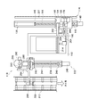
- Plan view showing the overall configuration of the wafer peeling cleaning device Plan view showing the configuration of the wafer separation sheet-fed portion
- the top view which shows the structure of a peeling apparatus.
- Front view showing the configuration of the delivery device
- Enlarged side view of the main part showing the details of the adsorption part for peeling
- Enlarged front view of essential parts showing details of adsorption section for peeling
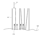
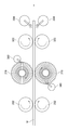
- Explanatory diagram of action of peeling work Side view showing the structure of the single-wafer cleaning unit
- Plan view showing the configuration of the transport unit
- the top view which shows the structure of a collection part
- the single-wafer pre-rinse unit 354 performs brush cleaning with a rotating brush while applying the pre-rinse liquid from the pre-rinse liquid nozzle to the back surface of the conveyed wafer. After cleaning, the compressed air is jetted to drain the liquid. Then, it is conveyed to the single-wafer rinse unit 356 in the next step.
- the wafer transfer robot 508 receives the wafer W from the detection unit 400, and sorts and stores the wafer W in the cassettes of the wafer recovery units 502, 504, and 506 based on the detection result.
- FIG. 2 is a plan view showing the structure of the wafer separation sheet-fed portion 100
- FIG. 3 is a plan view showing the structure of the separation device 114
- FIG. 4 is a plan partial sectional view showing the structure of the delivery device 118
- FIG. 6 is a side view showing the configuration of the stripping device 114
- FIG. 7 is a front view showing the configuration of the wafer stripping single-wafer unit 100
- FIG. 8 is a front view showing the configuration of the delivery device 118.
- 9 is a partial side sectional view showing the structure of the delivery device 118.
- the wafer-peeling single-wafer unit 100 is mainly composed of a hot water tank 112, a peeling device 114, and a delivery device 118.
- the configuration of the hot water tank 112 will be described.
- the hot water tank 112 is formed in a rectangular box shape, and the hot water 120 is stored therein.
- the wafer W separated from the slice base S is set in the work holding part 122 provided in the hot water tank 112. Then, the wafer W is set on the work holding part 122, so that the slice base S bonded to the wafer W is immersed in the hot water 120. At this time, it is preferable that not all of the wafer W is immersed in the hot water 120, but 2 to 3 cm above the portion of the wafer W fixed with wax.
- the schematic configuration of the peeling device 114 will be described mainly with reference to FIG.
- the peeling device 114 is a device that peels the wafers W set in the hot water tank 112 from the slice base S one by one.
- a pair of first guide rails 136, 136 are arranged near the right side portion of the hot water tank 112 along the longitudinal direction of the hot water tank 112.
- a first slide table (traveling body) 140 is slidably supported on the first guide rails 136 and 136 via linear guides 138 and 138 (FIG. 5).
- a stripping unit 150 for stripping the wafer W from the slice base S is provided on the first slide table 140. As shown in FIGS. 3, 5, and 6, the peeling unit 150 has a bearing block 152 provided on the first slide table 140. A support shaft 156 provided at the base end of the swing frame 154 is swingably supported by the bearing block 152.
- a swing rotary actuator 160 is installed on the first slide table 140 via a bracket 158, and a drive gear 162 is fixed to the output shaft of the swing rotary actuator 160.
- a driven gear 164 is meshed with the drive gear 162, and the driven gear 164 is fixed to the tip of the rotary shaft 168.
- the rotating shaft 168 is rotatably supported by a bearing member 170, and the bearing member 170 is supported by a support plate 172 fixed to the swing rotary actuator 160.
- a rotary plate 174 (FIGS. 5 and 6) formed in a disk shape is coaxially fixed to the driven gear 164, and one end of a connecting rod 176 is connected to the rotary plate 174 by a pin 178. .. The other end of the connecting rod 176 is connected to the swing frame 154 by a pin 180.
- the swing frame 154 swings around the support shaft 156 provided at the base end thereof by driving the swing rotary actuator 160. That is, when the swinging rotary actuator 160 is driven, the rotating plate 174 rotates reciprocally within the range of 180°, and the reciprocating rotation is transmitted to the swinging frame 154 via the connecting rod 176, and the swinging frame 154 swings.
- a bearing unit 182 is provided on the upper end of the swing frame 154, and two rotating shafts 186 and 188 are rotatably supported by the bearing unit 182. Arms 190 and 192 are fixed to the tip ends of the rotary shafts 186 and 188, respectively, and the tip ends of the arms 190 and 192 are connected to the pad support plate 198 via pins 194 and 196, respectively.
- a pair of first and second peeling suction pads 200 and 201 are arranged on the pad support plate 198 at a predetermined interval. The first and second peeling suction pads 200 and 201 vacuum-chuck the wafer W. And hold.
- a support plate 202 is attached to the back surface of the swing frame 154, and a lift rotary actuator 204 is installed on the support plate 202.
- a fan-shaped rotating plate 206 is fixed to the output shaft of the lifting rotary actuator 204, and one end of a connecting rod 208 is connected to the rotating plate 206 by a pin 210. The other end of the connecting rod 208 is connected to the one arm 190 by a pin 212.
- the first and second peeling suction pads 200, 201 provided on the pad support plate 198 are moved vertically upward and downward by driving the lifting rotary actuator 204. That is, when the lifting rotary actuator 204 is driven, the rotary plate 206 reciprocally rotates in the range of 180°, and the reciprocal rotation is transmitted to the arm 190 via the connecting rod 208, and one arm 190 moves vertically in a reciprocal angular motion. I do.
- the arm 192 on the other side also performs a reciprocating angular motion to make a reciprocating angular motion, and as a result, the first and second peeling suction pads 200, 201 provided on the pad support plate 198. Is lifted vertically upwards.
- the first and second peeling suction pads 200 and 201 that suction-hold the wafer W are moved up and down by driving the lift rotary actuator 204. Further, since the pad supporting plate 198 provided with the first and second peeling suction pads 200, 201 is connected to the swing frame 154 via the arms 190, 192, the swing frame 154 swings. By doing so, it swings back and forth.
- the first and second peeling suction pads 200, 201 swing in the front-rear direction by driving the swinging rotary actuator 160, and move up and down by driving the lifting rotary actuator 204. Then, the wafer W is peeled from the slice base S by the first and second peeling suction pads 200 and 201 as follows.
- the end surface of the wafer W set in the hot water tank 112 is sucked and held by the first and second peeling suction pads 200 and 201. Then, the swing rotary actuator 160 is driven to swing the first and second peeling suction pads 200, 201 in the front-rear direction (direction along the axis of the wafer).
- the adhesive that bonds the wafer W and the slice base S is immersed in the hot water 120, the adhesive is sufficiently softened. Therefore, the wafer W is separated from the slice base S by being shaken a plurality of times.
- the lift rotary actuator 204 is driven, and the first and second peeling suction pads 200 and 201 move upward while holding the peeled wafer W. Then, it stops at a predetermined delivery position.
- the wafer W transferred to the transfer position is transferred to the transfer device 118, then transferred to the shuttle conveyor 312 by the transfer device 118, and transferred to the next process by the shuttle conveyor 312.
- the first and second peeling suction pads 200, 201 after the transfer of the wafer W is finished are driven downward by being driven by the lifting rotary actuator 204 and returned to the original peeling work position.
- the wafer W is peeled from the slice base S by swinging the end surface of the wafer W by the first and second peeling suction pads 200 and 201.
- the first and second peeling suction pads are included. Some of them have been peeled off from the slice base S before being rocked by 200 and 201.
- a fall stop plate 214 for preventing the wafer W from falling forward is disposed at a position in front of the wafer W to be peeled off.
- the fall prevention plate 214 is provided on the support plate 202 on which the lifting rotary actuator 204 is installed, and swings together with the first and second peeling suction pads 200, 201.
- the first and second adsorption pads 200 and 201 for peeling move up and down through a passage 214a formed in the stop plate 214.
- a two-piece prevention plate 216 is fixed to the upper part of the fall prevention plate 214, and the wafer W separated from the slice base S passes through a slit 216 a formed in the two-piece prevention plate 216 and is predetermined. Will be transferred to the delivery position.
- the slit 216a is formed with a width that allows exactly one wafer W to pass through (for example, a width of 1.1 to 1.5 times the thickness of the wafer W), so that two wafers are peeled at the same time.
- the width of the slit 216a is 1.1 to 1.5 times the thickness of the wafer W to prevent simultaneous transfer of two wafers and prevent damage to the surface. it can.
- the surface of the stop plate 214 is water-repellent, such as fluororesin processed.
- the fall prevention plate 214 is not water-repellent processed, a water film is formed on the surface thereof, and the wafer W sticks to the fall prevention plate 214, so that when the wafer W is transferred to the delivery position through the slit 216a, This is because the first and second suction pads 200 and 201 for peeling may be displaced from or separated from each other, which makes it difficult to transfer. Since the water film is not formed by subjecting the surface of the stop plate 214 to the water repellent process, it is possible to prevent the wafer W from sticking to the stop plate 214.
- the surface of the fall-stop plate 214 not a mirror-finished state but rather a rough surface, it is possible to suppress or prevent the wafer W from being adsorbed to the fall-stop plate 214, and this and the water-repellent treatment By using them together, it is possible to more reliably prevent the wafer W from sticking to the stop plate 214.
- the two wafers are adhered to the first wafer when passing through the slit 216a of the two-piece prevention plate 216. Since the second wafer cannot pass through the slit 216a and falls, it can always be transferred one by one to the delivery position. In this case, since the wafer which cannot pass through the slit 216a and is dropped is prevented from falling forward by the stop plate 214, the wafer can be reliably collected at the next peeling.
- a column 274 is vertically installed on the second slide table 240 of the drive unit 222.
- a support frame 276 is vertically installed upright on the top of the column 274, and a rotary rotary actuator 278 is horizontally installed on the support frame 276.
- a drive gear 280 is meshed with the output shaft of the rotary rotary actuator 278, and a driven gear 282 fixed to the rotary shaft 284 is meshed with the drive gear 280.
- the swivel shaft 284 is rotatably supported by a bearing unit 286 installed on the top of the support frame 276, and swivels in a range of 180° by driving a swiveling rotary actuator 278.
- a swivel frame 288 is fixed to the base end of the swivel shaft 284, and a rotary shaft 290 is rotatably supported by the swivel frame 288.
- An output shaft of a direction changing rotary actuator 292 installed on the revolving frame 288 is fixed to a base end portion of the rotating shaft 290. By driving the direction changing rotary actuator 292, the rotation shaft is rotated within a range of 90°. Move.
- An L-shaped swivel arm 294 is fixed to the tip of the rotary shaft 290, and a support plate 296 is fixed to the tip of the swivel arm 294.
- a pad advancing/retreating cylinder 298 is provided on the support plate 296, and a delivery suction pad 300 is provided at the tip of the rod of the pad advancing/retreating cylinder 298.
- the wafer W peeled by the first and second peeling suction pads 200 and 201 of the peeling device 114 is transferred to a predetermined transfer position and then transferred to the transfer suction pad 300.
- the wafer W separated by the separation device 114 is received and the received wafer W is transferred onto the shuttle conveyor 312 as follows.
- the wafer W separated from the slice base S is lifted while being sucked and held by the first and second peeling suction pads 200 and 201, and is transferred to a predetermined delivery position.
- the delivery suction pad 300 is already on standby at the delivery position, and the wafer W is located coaxially with the axis of the delivery suction pad 300.
- the pad advancing/retreating cylinder 298 is then driven to advance the delivery suction pad 300 by a predetermined amount toward the wafer W.
- the delivery suction pad 300 comes into close contact with the end surface of the wafer W.
- the delivery suction pad 300 is driven, and the wafer W is suction-held by the delivery suction pad 300.
- the fact that the wafer W is suction-held on the delivery suction pad 300 is detected by a pressure switch (not shown) provided on the delivery suction pad 300 side.
- the pressure switch can be installed at any position where the pressure in the delivery suction pad 300 can be detected and at a position where suction of the wafer W is not hindered.
- the delivery suction pad 300 that has received the wafer W starts driving the pad advancing/retreating cylinder 298 in response to the detection signal from the pressure switch, and retracts from the first peeling suction pad 200.
- the first peeling suction pad 200 that has delivered the wafer W starts to descend by the detection signal from the pressure switch and returns to the original peeling work position.
- the delivery suction pad 300 moves backward, the rotary rotary actuator 278 is driven, and the rotary arm 294 pivots 180°.
- the wafer W is transferred to the position above the shuttle conveyor 312.
- a sensor, a device, or the like having a similar function such as a touch sensor can be used instead of the pressure switch.
- the first slide table 140 on which the peeling unit 150 is installed is located at one end (lower end in FIG. 2) of the first guide rail 136 (this position is referred to as a peeling work start position).
- the second slide table 240 on which the delivery device 118 is installed is located at the other end (upper end in FIG. 2) of the second guide rail 236.
- the wafer W multi-cut with a wire saw is set in the work holding part 122 provided in the hot water tank 112.
- the slice base S to which the wafer W is bonded is immersed in the hot water 120 stored in the hot water tank 112.
- the wafer W may be set manually by an operator, or may be automatically conveyed to the work holding unit 122 by a manipulator (not shown) and automatically set.
- the control device first drives the second feed motor 248 to move the second slide table 240 downward in FIG. Next, the second slide table 240 is positioned at a predetermined start position of the delivery work. Then, when the second slide table 240 is located at the start position of the delivery work, the peeling work of the wafer W is started.
- the control device drives the first feed motor 148 and the second feed motor 248 in synchronization with each other, and moves the first slide table 140 and the second slide table 240 forward (moves upward in FIG. 2).
- a non-contact type position sensor 214S is provided on the pad supporting plate 198 of the peeling device 114 provided on the first slide table 140, and the position sensor 214S has a predetermined distance to the end surface of the wafer W. It works when it reaches.
- the control device stops driving the first feed motor 148 and the second feed motor 248 by inputting the operation signal of the position sensor 214S, and stops the first slide table 140 and the second slide table 240.
- the first and second peeling suction pads 200 and 201 of the peeling device 114 provided on the first slide table 140 come into contact with the end surface of the wafer W.
- the control device drives the first and second peeling suction pads 200 and 201 that are in contact with the end surface of the wafer W, and causes the first and second peeling suction pads 200 and 201 to suck and hold the wafer W.
- FIG. 10 is an enlarged side view of a main part showing the details of the peeling adsorption portion
- FIG. 11 is an enlarged front view.
- the tilting plate 214 has the end surface side of the wafer W as a reference surface, and the pressing plate 214-1 made of resin for protecting the surface and the stainless plate 214 made of stainless steel on the opposite side for ensuring the flatness of the pressing plate 214-1. -2.
- the surface of the pressing plate 214-1 made of resin which is the surface on the side where the wafer W contacts, is preferably subjected to water repellent treatment such as fluororesin treatment as described above. It is more preferable that the surface is not a mirror surface and has a surface roughness such that the wafer W is not adsorbed.
- the wafer W is bonded to the slice base S with an adhesive, and is arranged so as to be on the upper side of the mounting plate M, and then set on the work holding portion 122 of the hot water tank 112.
- the adhesive is sufficiently softened.
- An air supply mechanism is provided beside the slice base S, and air nozzles 80 and 81 are provided on both lower side surfaces of the wafer W.
- the air nozzles 80 and 81 are installed so as to blow air from the lower side to the upper side of the side surface 2 of the wafer W, that is, to blow the air vigorously.
- a water supply nozzle (not shown) is provided vertically above the wafer W near the center of the wafer.
- the suction holding of the wafer W by the first and second peeling suction pads 200 and 201 is performed as follows. First, the second peeling suction pad 201 contacts the end surface of the wafer W.
- the second peeling suction pad 201 is arranged below the central axis of the wafer W, and can be expanded and contracted in the axial direction like a bellows type vacuum suction pad, so that the second peeling suction pad 201 is covered from a surface perpendicular to the axial direction. Even if the surface of the adsorbent is inclined to some extent, the adsorption part of the adsorption pad is of a type that can be inclined to the surface of the adsorbed object to some extent.
- FIG. 12 is an explanatory diagram of the operation of the peeling work.
- the air nozzles 80 and 81 are used to remove the wafer W from both sides as shown by arrows F and G. Air is blown from side to side.
- the water is supplied from the center, and it is possible to ensure a certain gap in the center. Then, by flowing air from both side surfaces of the wafer W, the gaps on both sides can be maintained in a well-balanced manner, and the edges between the wafers can be cut cleanly.
- the control device drives the swinging rotary actuator 160 to swing the swinging frame 154 back and forth to move the first and second peeling suction pads 200 and 201 back and forth (direction along the axis of the wafer). Rock to.
- the first and second peeling suction pads 200 and 201 swing around the bonded portion between the wafer W and the slice base S as the swing center. Therefore, the wafer W is swung a plurality of times by the first and second suction pads 200 and 201 for peeling, and is easily peeled from the slice base S. Further, the wafer W can be peeled from the root by swinging back and forth during peeling, and the wafer W can be efficiently peeled as a whole.
- the control device stops the driving of the swing rotary actuator 160 when the first and second peeling suction pads 200, 201 are swung a predetermined number of times.
- the lifting rotary actuator 204 is driven to rotate the arms 190 and 192 upward, and the first and second peeling suction pads 200 and 201 are moved upward.
- the central axis of the wafer W is firmly fixed by the first peeling suction pad 200.
- the stuck wafer W is slit when passing through the slit 216a. Since it is peeled off when passing through 216a, it is possible to always take out only one wafer W that is adsorbed by the first exfoliation adsorption pad 200.
- the fallen wafer that cannot pass through the slit 216a is prevented from falling forward by the fall prevention plate 214, so that it is reliably collected at the next peeling.
- the end surface side of the wafer W contacts the pressing plate 214-1 made of resin (for example, fluororesin) having extremely high surface lubricity, so that scratches are prevented.
- the first and second peeling suction pads 200, 201 that have moved upward stop using the chain line position in FIG. 8 as the delivery position.
- the delivery suction pad 300 of the delivery device 118 is on standby, and the wafer W whose end surface is suction-held by the first peeling suction pad 200 that firmly sucks the central axis of the wafer W is used for delivery. It is located coaxially with the axis of the suction pad 300.
- the delivery position is a position where the delivery suction pad 300 is substantially horizontal (the position where the revolving arm 294 is horizontal in FIG. 8) and the wafer W remains in the vertical state, so that the influence of wafer deflection due to gravity is exerted. It is a difficult position to receive. Further, after the transfer, the suction pads 200 and 201 can immediately return to the peeling operation of the next wafer W, and the efficient peeling work can be sequentially continued.
- the control device drives the pad advancing/retreating cylinder 298 to advance the delivery suction pad 300 toward the wafer W by a predetermined amount. ..
- the delivery suction pad 300 is in close contact with the back surface of the end surface of the wafer W sucked by the first peeling suction pad 200.
- the wafer W is suction-held by the delivery suction pad 300 on the back surface as well as the end surface on the first peeling suction pad 200 side.
- the fact that the wafer W is suction-held on the delivery suction pad 300 is detected by a pressure switch (not shown) provided on the delivery suction pad 300 side. Then, according to this detection signal, the vacuum suction of the first and second peeling suction pads 200, 201 is released, that is, air is introduced.
- the delivery suction pad 300 is a flat vacuum pad having a flat surface like the first peeling suction pad 200, and firmly sucks the central axis of the wafer W. As a result, the wafer W is transferred from the first peeling suction pad 200 to the delivery suction pad 300, and the central axis of the wafer W is firmly sucked by the delivery suction pad 300. Therefore, it becomes possible to handle the wafer W in a state suitable for transporting the wafer W, and it is possible to eliminate the risk of dropping during the process.
- the controller drives the pad advancing/retreating cylinder 298 to retract the delivery suction pad 300 from the first peeling suction pad 200.
- the control device drives the elevating rotary actuator 204 to rotate the arms 190 and 192 downward to move the first and second peeling suction pads 200 and 201 downward. , Return to the original peeling work position.
- control device drives the swiveling rotary actuator 278 after driving the pad advancing/retreating cylinder 298 to swivel the swivel arm 294 by 180° and transfers the wafer W to a position above the shuttle conveyor 312. After the transfer, the direction changing rotary actuator 292 is driven. The swivel arm 294 rotates 90° about the rotation axis 290.
- both end surfaces of the wafer W become parallel to the shuttle conveyor 312.
- the control device drives the pad advancing/retreating cylinder 298 to advance the delivery suction pad 300 toward the shuttle conveyor 312. As a result, the wafer W is placed on the shuttle conveyor 312. Next, the control device stops the driving of the transfer suction pad 300 and transfers the wafer W to the shuttle conveyor 312.
- the control device After stopping the driving of the delivery suction pad 300, the control device drives the pad advancing/retreating cylinder 298 to retract the delivery suction pad 300 from the shuttle conveyor 312, and drives the shuttle conveyor 312 to move the wafer W to the next position. Transfer to the process. After driving the pad advancing/retreating cylinder 298, the control device drives the direction changing rotary actuator 292 and the turning rotary actuator 278 to return the delivery suction pad 300 to the original delivery position.
- the suction pads 200, 201 are stripping the next wafer W, so the stripping operation for the second wafer W is completed. Therefore, the wasteful time is reduced and the efficient peeling work is sequentially continued.
- the delivery of the first wafer W is completed in a series of steps, and the suction pads 200 and 201 are returned to their original peeling work positions as the delivery suction pad 300 is retracted.
- the control device drives the first feed motor 148 and the second feed motor 248 in synchronization with each other to advance the first slide table 140 and the second slide table 240 by a predetermined amount.
- the first and second peeling suction pads 200, 201 come into contact with the end surface of the wafer W to be peeled off for the second sheet.
- the control device separates the second wafer W by the same method as described above.
- the wafer W adhered to the slice base S is sequentially peeled off as described above, and then conveyed to the next step, and the peeling work for one cycle is completed.
- the transfer unit 310 receives the wafer W separated and separated by the wafer separation and separation unit 100, and conveys the wafer W to the next single-wafer cleaning unit 350.
- the transfer section 310 is provided with a shuttle conveyor 312, and the wafer W is transferred to the single-wafer cleaning section 350 by the shuttle conveyor 312.
- the single-wafer cleaning unit 350 performs single-wafer cleaning of the wafers W separated and separated by the wafer separation/separation unit 100.
- the single-wafer cleaning unit 350 includes a single-wafer brush cleaning unit 352, a single-wafer pre-rinsing unit 354, and a single-wafer rinsing unit 356.
- the single-wafer rinsing unit 356 has substantially the same configuration as the single-wafer brush cleaning unit 352.
- the back surface of the wafer conveyed by the roller conveyor of the single-wafer rinsing unit is brush-cleaned by the rotary brush while applying the rinsing liquid from the rinsing liquid nozzle. After cleaning, the wafer W is transported to the next detection unit 400 by the roller conveyor.
- the detection unit 400 detects the presence or absence of cracks, chips, and adhesive residue for each wafer W that has been cleaned, and measures the thickness of each wafer W.
- the detection unit 400 lifts the transfer unit 402 for transferring the wafer W, which has been cleaned by the single-wafer cleaning unit 350, to a predetermined receiving position and the wafer W transferred to the receiving position to a predetermined detection position.
- a rotary drive unit that rotates, a thickness measurement unit that measures the thickness of the wafer W that is rotated by the rotary drive unit, and a crack, a chip, or an adhesive residue on the wafer W that is rotated by the rotary drive unit.
- the defective wafer detection unit is composed of a defective wafer detection unit and a delivery unit for delivering the detected wafer W to the wafer transfer robot of the next recovery unit 500.
- the round belt conveyor 411 At the end position of the round belt conveyor 411, five positioning pins 412, 412,... Are arranged so as to form an arc, as shown in FIG. 14, and the positioning pins 412, 412,.
- the wafer W conveyed by 411 is brought into contact with the wafer W so that the wafer W is positioned at a predetermined receiving position. Further, when the wafer W comes into contact with the positioning pins 412, 412,..., A sensor (not shown) is activated, and by driving this sensor, the driving of the round belt conveyor 411 is stopped. Then, the wafer W that has been detected is delivered to the wafer transfer robot 508 of the recovery unit 500.
- FIG. 15 is a plan view showing the configuration of the recovery unit 500, and the wafer recovery units 502A and 502B are respectively provided with upper and lower two-stage cassette holders (not shown).
- the cassette holder is supported by a cassette positioning mechanism (not shown) so as to be movable up and down, and two wafer recovery cassettes 510A and 510B for recovering the wafer W are set in the cassette holder two by two.
- the defective wafer recovery unit 504 and the adhesive remaining wafer recovery unit 506 each include a cassette holder (not shown), and the cassette holder is movably supported by a cassette positioning mechanism (not shown). ing. Then, a defective wafer recovery cassette 512 for recovering the defective wafer W and an adhesive residual wafer recovery cassette 514 for recovering the adhesive residual wafer W are set in the cassette holder.
- the wafer W mounted on the lifter is first transferred to the rough cleaning unit 10 by the lifter. Then, there is shower cleaning, and the slurry attached at the time of cutting is removed. The shower cleaning in the rough cleaning unit 10 is performed while being mounted on the lifter, and when the shower cleaning is completed, the wafer is transferred to the wafer-separated single-wafer unit 100.
- the wafer W transferred to the wafer-separating sheet-by-sheet unit 100 is first inverted upside down by an inversion mechanism provided in the lifter (the wafer W is placed above the mounting plate M). After that, it is set in the work holding part 122 of the hot water tank 112.
- the wafers W set in the work holding unit 122 are peeled from the slice base S one by one by the first and second peeling suction pads 200 and 201, and the peeled wafers W are sequentially transported by the shuttle conveyor of the transport unit 310. Transferred to 312. Then, it is conveyed to the single-wafer cleaning unit 350 by the shuttle conveyor 312.
- the wafer peeling/cleaning apparatus 1 can peel and clean sliced wafers cut by a multi-cutting method (a method of simultaneously cutting different types of ingots for one cutting). A case where a wafer cut by the multi-cutting method is peeled off and washed will be described.
- Wafers cut by the multi-cutting method need to be collected for each type of wafer, so they are processed as follows.
- the steps until the wafer is transferred to the wafer separation sheet-fed portion 100 are the same as those of the wafer cut by the above-described normal cutting method.
- a partition plate (not shown) of a partition device is set between lots of each wafer W. Then, when the partition plate is set, the peeling work by the first peeling suction pad 200 is started. The peeling operation is first performed from the first lot of wafers W, and the peeled wafers W are sequentially transferred onto the shuttle conveyor 312 of the transfer unit 310.
- the second partition plate (not shown) inserted between the second lot and the third lot is detected, and the control device detects the second partition plate. To do. After that, the wafer to be peeled is determined to be the wafer W of the third lot.
- the wafer peeling single-wafer unit 100 when the end face of the wafer is sucked and held by the peeling suction pad and peeled one by one, the air is blown by the air nozzle, so that the gap between the wafers in the batch state A good balance can be secured, damage to the wafer can be eliminated, and only one wafer can be efficiently lifted. Then, after that, the steps of the transport unit 310, the single-wafer cleaning unit 350, the detection unit 400, and the recovery unit 500 can be smoothly progressed, and an efficient wafer peeling and cleaning apparatus 1 can be provided.
- the present invention also includes the following.
- Appendix A Item 1 A large number of wafers in a batch state, which have been simultaneously cut, are separated from the slice base one by one at the wafer separation sheet-feeding section to be separated into single sheets, and the separated wafers are conveyed to a single-wafer cleaning section for single-wafer cleaning, and after cleaning ,
- the wafer separation sheet-fed portion is A hot water tank formed in a rectangular box shape and storing hot water, A work holding unit installed in the hot water tank to hold the wafer to be peeled, A peeling suction pad for sucking and holding one end surface of the wafer, A first guide rail arranged along the longitudinal direction of the hot water tank; A first feed motor for moving the peeling adsorption pad along the first guide rail along the longitudinal direction of the hot water tank; A lifting rotary actuator that vertically moves the peeling suction pad vertically, An air nozzle provided on the
- Appendix A Item 2 The wafer peeling and cleaning apparatus according to appendix A, wherein the air nozzles are provided on both side surfaces of the wafer.
- a water supply nozzle is provided above the wafer vertically, and when peeling the wafers one by one, hot water or water is supplied from near the center above the wafer vertically.
- the wafer peeling cleaning apparatus according to any one of 1.
- a swing rotary actuator that swings the peeling suction pad in the direction along the axis of the wafer is provided, and the peeling suction pad is swung to swing the peeling suction pad to move the wafer.
- the wafer peeling/cleaning apparatus according to any one of appendices A to 1, which is peeled from the slice base.
- the following problems of the invention described in Patent Document 1 can be solved.
- the invention described in Patent Document 1 since the wafer is rocked in the direction along the axis, it is desirable in terms of efficiently separating the wafer, but when the wafer is lifted at the wafer separation sheet-fed portion, the next wafer Can be lifted with him.
- the standby wafer next to the lifted wafer and the second standby wafer next to it may adhere to each other, which may cause damage such as cracks, chips, chipping, and microcracks on the wafer. ..
- the air nozzle is provided on the side surface of the wafer, and when the edge surface of the wafer is sucked and held by the suction pad for peeling and peeled one by one, air is blown by the air nozzle. It is possible to secure a well-balanced gap between batch-shaped wafers. Therefore, when the wafer is lifted, the next wafer is not lifted up together, and it is possible to efficiently lift one wafer without damaging the wafer.
- Appendix B Item 2 The wafer peeling/cleaning apparatus according to Appendix B, wherein the fall prevention plate is provided with a resin pressing plate on the end face side of the wafer.
- Appendix B Item 3 The wafer stripping and cleaning apparatus as described in appendix B, wherein a stainless steel plate made of stainless is provided on the opposite side of the pressing plate.
Landscapes
- Engineering & Computer Science (AREA)
- Mechanical Engineering (AREA)
- General Engineering & Computer Science (AREA)
- Container, Conveyance, Adherence, Positioning, Of Wafer (AREA)
- Mechanical Treatment Of Semiconductor (AREA)
- Cleaning Or Drying Semiconductors (AREA)
Abstract
【課題】ウェーハへのダメージを与えることなく、剥離作業から受渡装置によって枚葉洗浄部に搬送するまでの時間を短縮して全体として効率を向上する。 【解決手段】ウェーハ剥離洗浄装置において、ウェーハ剥離枚葉部100は、第1及び第2剥離用吸着パッド200、201と、倒止板214と、倒止板214の上部にスリット216aが形成された2枚取り防止板216と、を有し、受渡装置118は、受渡用吸着パッド300と、受渡用吸着パッド300にウェーハWが吸着保持されたこと検知する圧力スイッチと、を有し、圧力スイッチによる検知信号によって、第1及び第2剥離用吸着パッド200、201の真空吸着を解除すると共に、受渡用吸着パッド300の後退及び第1及び第2剥離用吸着パッド200、201の下降を開始する。
Description
本発明はウェーハ剥離洗浄装置に係り、特にワイヤソーで多数枚に同時切断され、バッチ状態(束ねられた)とされたウェーハをスライスベースから剥離して枚葉化し、洗浄するウェーハ剥離洗浄装置に関する。
ワイヤソーでインゴットを切断すると、ウェーハは全てスライスベースに接着された状態で切り出される。このため、ウェーハはスライスベースから剥離して枚葉化する必要がある。また、ワイヤソーで切断された直後のウェーハには、加工液等が付着しているため、洗浄して加工液を除去する必要がある。
従来、このウェーハの剥離作業と洗浄作業は、一台のウェーハ剥離洗浄装置で行っていた。また、ウェーハ剥離洗浄装置は、粗洗浄部、ウェーハ剥離枚葉部、洗浄部及び回収部で構成されており、切断直後のウェーハは、まず、粗洗浄部に搬送されて粗洗浄される。そして、粗洗浄されたバッチ状態のウェーハは、ウェーハ剥離枚葉部に搬送されて、そこで1枚ずつスライスベースから剥離されて枚葉化される。スライスベースから剥離されたウェーハは、受渡装置によって枚葉洗浄部に搬送される。そして、枚葉洗浄され、回収部において1枚ずつ回収されてカセットに収納される。
ウェーハ剥離枚葉部では、効率良くウェーハを剥離するため、所定の間隔をもって一対の剥離用吸着パッドを配設し、一対の剥離用吸着パッドによってウェーハを真空吸着して保持する。そして、剥離用吸着パットを前後方向に揺動し、昇降用ロータリーアクチュエータによって、昇降移動して所定の受渡位置で停止することが知られ、特許文献1に記載されている。
特許文献1に記載のものでは、単に、一対の剥離用吸着パッドによってウェーハを真空吸着して前後方向に揺動し、昇降移動するので、効率良くウェーハを剥離する点では望ましいが、剥離されたウェーハを持ち上げてから受渡位置で受渡用吸着パッドに確実に受け渡すには十分でない。特に、効率向上のために昇降移動の速度を上げると、途中でウェーハを落下、あるいはウェーハの姿勢が不安定になって傷つける恐れがある。
また、ウェーハが傾いていたとき、剥離用吸着パッドでうまく吸着できないという課題もあった。
また、ウェーハが傾いていたとき、剥離用吸着パッドでうまく吸着できないという課題もあった。
本発明の目的は、上記従来技術の課題を解決し、ウェーハが傾いていたとしても剥離用吸着パッドで確実にウェーハを吸着し、ウェーハを小さな力で簡単に1枚ずつ剥離すると共に、剥離したウェーハを受渡装置、あるいは枚葉洗浄部に確実に搬送することで、時間を短縮して全体として効率を向上したウェーハ剥離洗浄装置を得ることにある。
上記課題を解決するため、本発明は、多数枚同時に切断されたバッチ状態のウェーハをウェーハ剥離枚葉部において1枚ずつスライスベースから剥離して枚葉化し、剥離した前記ウェーハを枚葉洗浄部に搬送して枚葉洗浄し、洗浄後、回収部でカセットに回収するウェーハ剥離洗浄装置において、前記ウェーハ剥離枚葉部は、矩形の箱型に形成され熱水が貯留される熱水槽と、前記熱水槽内に設置され前記ウェーハを保持するワーク保持部と、該ワーク保持部に前記ウェーハが保持された状態で、中心軸が前記ウェーハの中心軸と一致するように配置された第1剥離用吸着パッドと、該第1剥離用吸着パッドより下側に配置され、軸方向に伸縮する第2剥離用吸着パッドと、前記熱水槽の長手方向に沿って配設された第1ガイドレールと、前記第1ガイドレールに沿って前記第1及び第2剥離用吸着パッドを前記熱水槽の長手方向に沿って移動させる第1送りモータと、前記第1及び第2剥離用吸着パッドを鉛直上方に昇降移動する昇降用ロータリーアクチュエータと、を備えたものである。
また、上記において、前記第2剥離用吸着パッドは、ベローズ型真空吸着パッドとされたことが望ましい。
さらに、前記第1剥離用吸着パッドは、表面がフラットな平形真空パッドとされ、前記第2剥離用吸着パッドより吸着力が強いことが望ましい。
さらに、バッチ状態の前記ウェーハから1枚ずつ剥離して枚葉化する際、前記ウェーハの吸着保持は、前記ウェーハの端面に前記第2剥離用吸着パッドが当接して引き寄せ、その後、前記第1剥離用吸着パッドにより前記ウェーハの中心軸を吸着することで行われることが望ましい。
さらに、バッチ状態の前記ウェーハから1枚ずつ剥離して枚葉化する際に前記ウェーハが前方に倒れるのを防止する倒止板を有し、前記第2剥離用吸着パッドはバッチ状態の前記ウェーハの接着部近傍を中心として前記ウェーハを前記倒止板側へ引き寄せることが望ましい。
さらに、前記第1及び第2剥離用吸着パッドを前記ウェーハの軸線に沿った方向に揺動させる揺動用ロータリーアクチュエータを設け、前記揺動用ロータリーアクチュエータを駆動して前記第1及び第2剥離用吸着パッドを揺動させることにより、前記ウェーハを前記スライスベースから剥離することが望ましい。
さらに、前記ウェーハの鉛直上方に水供給ノズルを設け、前記ウェーハを1枚ずつ剥離する際に、前記ウェーハの鉛直上方で中心付近から熱水又は水を供給することが望ましい。
さらに、前記ウェーハの両側面に設けられたエアノズルを有し、前記熱水槽にセットされた前記ウェーハの端面を前記第1及び第2剥離用吸着パッドで吸着保持して前記ウェーハを1枚ずつ剥離する際に、前記エアノズルにより前記ウェーハの側面にエアーをブロー供給することが望ましい。
さらに、前記エアノズルは、前記ウェーハの下側から上側に向かってエアーをブロー供給することが望ましい。
さらに、前記エアノズルは、前記ウェーハを1枚剥離する際に、バッチ状態の複数枚に対してエアーをブロー供給することが望ましい。
本発明によれば、ウェーハが傾いていたとしても剥離用吸着パッドで確実にウェーハを吸着し、剥離作業から受渡装置によって枚葉洗浄部に搬送するまでの時間を短縮して全体として効率を向上したウェーハ剥離洗浄装置を得ることができる。
以下、本発明の実施形態について図面を参照して詳細に説明する。図1は、本発明に係るウェーハ剥離洗浄装置1の構成を示す平面図、図2は、ウェーハ剥離枚葉部100の構成を示す平面図である。図1に示すように、本実施の形態のウェーハ剥離洗浄装置1は、粗洗浄部10、ウェーハ剥離枚葉部100、搬送部310、枚葉洗浄部350、検出部400及び回収部500を主要部として構成されている。各主要部の概要を説明する。
粗洗浄部10は、ワイヤソーで切断された直後のバッチ状態のウェーハW(スライスベースSに接着されたウェーハW)をシャワー洗浄して切断時に付着したスラリを除去する。粗洗浄部10は、ウェーハWの洗浄を行う粗洗浄装置12を備えている。粗洗浄装置12では、マウンティングプレートMを上側にして、スライス溝を下側にして浸漬し、洗浄する洗浄工程を有する。洗浄する際に上下にゆすりながら、溝内に水流を起こして洗浄する。洗浄が終了すると、粗洗浄部10から搬出されたウェーハは、そのままリフターによって次のウェーハ剥離枚葉部100に搬送される。
ウェーハ剥離枚葉部100では、バッチ状態のウェーハWをスライスベースSから1枚ずつ剥離して枚葉化する。そして、ウェーハ剥離枚葉部100は、図2に示すように熱水槽112、剥離装置114、受渡装置118を主要装置として構成されている。受渡装置118は、剥離装置114によってスライスベースSから剥離されたウェーハを受け取り、搬送部310のシャトルコンベア312に受け渡す装置である。
搬送部310は、ウェーハ剥離枚葉部100で剥離、枚葉化したウェーハWを受け取り、次の枚葉洗浄部350に搬送する。そして、搬送部310に備えられたシャトルコンベア312によってウェーハWを枚葉洗浄部350に搬送する。
枚葉洗浄部350は、ウェーハ剥離枚葉部100で剥離枚葉されたウェーハWを1枚ずつ枚葉洗浄する。枚葉洗浄部350は、枚葉ブラシ洗浄部352と枚葉プレリンス部354と枚葉リンス部356とから構成されている。枚葉ブラシ洗浄部352は、搬送されてきたウェーハWの裏表面に洗浄液をかけながらブラシ洗浄する。洗浄後は、洗浄液を次工程に持ち込まないようにするために、圧縮エアーを噴射して液切りする。そして、ブラシ洗浄が終了したウェーハWは、次工程の枚葉プレリンス部354に搬送される。
枚葉プレリンス部354は、搬送されてきたウェーハの裏表面にプレリンス液ノズルからプレリンス液をかけながら回転ブラシによってブラシ洗浄する。洗浄後は、圧縮エアーを噴射して液切りする。そして、次工程の枚葉リンス部356に搬送する。
枚葉リンス部356は、ウェーハの裏表面にリンス液ノズルからリンス液をかけながら回転ブラシによってブラシ洗浄する。洗浄後は、液切りされたウェーハWは、検出部400の丸ベルトコンベア411上に移送され、検出部400の所定の受取位置に搬送される。
検出部400は、洗浄が終了したウェーハWについて1枚1枚、割れ、欠け、及び接着剤残りの有無を検出すると共に、1枚1枚厚さを測定する。そして、検出が終了したウェーハWを回収部500のウェーハ搬送ロボット508に受け渡す。
ウェーハ搬送ロボット508は、多関節形のロボットであり、先端に、旋回自在なハンド部520が設けられ、ウェーハWは、そのハンド部520の先端に設けられた吸着パッド522で吸着保持されて搬送される。回収部500は、接着剤残りウェーハと不良ウェーハ(割れウェーハ、欠けウェーハ、厚さ不良ウェーハ、端材)を分別するため、正常なウェーハを回収する二つのウェーハ回収部502A、502Bと、不良ウェーハを回収する不良ウェーハ回収部504と、接着剤残りウェーハを回収する接着剤残りウェーハ回収部506とで構成される。
そして、ウェーハ搬送ロボット508は、検出部400からウェーハWを受け取り、その検出結果に基づいてウェーハWを各ウェーハ回収部502、504、506のカセットに分別して収納する。
次に、ウェーハ剥離枚葉部100の詳細について説明する。図2はウェーハ剥離枚葉部100の構成を示す平面図、図3は剥離装置114の構成を示す平面図、図4は受渡装置118の構成を示す平面部分断面図、図5は剥離装置114の構成を示す正面図、図6は剥離装置114の構成を示す側面図、図7はウェーハ剥離枚葉部100の構成を示す正面図、図8は受渡装置118の構成を示す正面図、図9は受渡装置118の構成を示す側面部分断面図である。ウェーハ剥離枚葉部100は、熱水槽112、剥離装置114、受渡装置118を主要装置として構成されている。
熱水槽112の構成について説明する。熱水槽112は矩形の箱型に形成されており、その内部に熱水120が貯留されている。スライスベースSから剥離するウェーハWは、熱水槽112内に設けられたワーク保持部122にセットされる。そして、ウェーハWがワーク保持部122にセットされることにより、ウェーハWに接着されたスライスベースSが熱水120中に浸漬される。このとき、熱水120中には、ウェーハWすべてが浸漬されるのでは無く、ウェーハWのうちワックスで固定された部分から2~3cm上まで浸漬されることが好ましい。
剥離装置114の概略構成について、主に図3にしたがって説明する。剥離装置114は、熱水槽112内にセットされたウェーハWをスライスベースSから1枚ずつ剥離する装置である。図2及び図5、図7に示すように、熱水槽112の右側部近傍には、熱水槽112の長手方向に沿って一対の第1ガイドレール136、136が配設されている。この第1ガイドレール136、136上には、リニアガイド138、138(図5)を介して第1スライドテーブル(走行体)140がスライド自在に支持されている。
第1スライドテーブル140の下面にはナット部材142(図5)が固着されており、ナット部材142は、一対の第1ガイドレール136、136の間に配設されたネジ棒144に螺合されている。ネジ棒144の両端部は、軸受部材146、146によって回動自在に支持されており、また、ネジ棒144の一方端には、第1ガイドレール136、136の一方端に設置された第1送りモータ148(図6)が連結されている。ネジ棒144は、第1送りモータ148を駆動することにより回動し、この結果、第1スライドテーブル140が第1ガイドレール136、136に沿って移動する。
第1スライドテーブル140上には、スライスベースSからウェーハWを剥離するための剥離ユニット150が設けられている。剥離ユニット150は、図3、5、6に示すように、第1スライドテーブル140上に軸受ブロック152が設けられている。軸受ブロック152には、揺動フレーム154の基端部に設けられた支軸156が揺動自在に支持されている。
第1スライドテーブル140上にはブラケット158を介して揺動用ロータリーアクチュエータ160が設置されており、揺動用ロータリーアクチュエータ160の出力軸には駆動ギア162が固着されている。駆動ギア162には、従動ギア164が噛合されており、従動ギア164は回転軸168の先端部に固着されている。回転軸168は軸受部材170によって回動自在に支持されており、軸受部材170は、揺動用ロータリーアクチュエータ160に固定された支持プレート172に支持されている。
従動ギア164には、円盤状に形成された回転プレート174(図5、6)が同軸上に固着されており、回転プレート174には、コネクティングロッド176の一方端がピン178によって連結されている。そして、コネクティングロッド176の他方端は、揺動フレーム154にピン180によって連結されている。
以上の構成により、揺動フレーム154は揺動用ロータリーアクチュエータ160を駆動することにより、その基端部に設けられた支軸156を中心に揺動する。すなわち、揺動用ロータリーアクチュエータ160を駆動すると回転プレート174が180°の範囲で往復回転し、その往復回転がコネクティングロッド176を介して揺動フレーム154に伝達され、揺動フレーム154が揺動する。
揺動フレーム154の上端部には、軸受ユニット182が設けられており、軸受ユニット182には二本の回転軸186、188が回動自在に支持されている。回転軸186、188の先端部には、それぞれアーム190、192が固着されており、アーム190、192の先端は、互いにピン194、196を介してパッド支持プレート198に連結されている。パッド支持プレート198には、所定の間隔をもって一対の第1及び第2剥離用吸着パッド200、201が配設されており、第1及び第2剥離用吸着パッド200、201はウェーハWを真空吸着して保持する。
揺動フレーム154の背面部には、支持プレート202が取り付けられており、支持プレート202には昇降用ロータリーアクチュエータ204が設置されている。昇降用ロータリーアクチュエータ204の出力軸には、扇形状に形成された回転プレート206が固着されており、回転プレート206にはコネクティングロッド208の一方端がピン210によって連結されている。そして、コネクティングロッド208の他方端は、一方のアーム190にピン212によって連結されている。
以上の構成により、パッド支持プレート198に設けられた第1及び第2剥離用吸着パッド200、201は、昇降用ロータリーアクチュエータ204を駆動することにより鉛直上方に昇降移動する。すなわち、昇降用ロータリーアクチュエータ204を駆動すると回転プレート206が180°の範囲で往復回転し、その往復回転がコネクティングロッド208を介してアーム190に伝達され、一方のアーム190が上下方向に往復角運動を行う。アーム190が往復角運動を行うと、他方側のアーム192も搖動テコとなって往復角運動を行い、この結果、パッド支持プレート198に設けられた第1及び第2剥離用吸着パッド200、201が鉛直上方に持ち上げられる。
ウェーハWを吸着保持する第1及び第2剥離用吸着パッド200、201は、昇降用ロータリーアクチュエータ204が駆動することにより昇降移動する。また、第1及び第2剥離用吸着パッド200、201が設けられているパッド支持プレート198は、アーム190、192を介して揺動フレーム154に接続されているので、揺動フレーム154が揺動することにより前後方向に揺動する。
すなわち、第1及び第2剥離用吸着パッド200、201は、揺動用ロータリーアクチュエータ160が駆動することにより前後方向に揺動し、昇降用ロータリーアクチュエータ204が駆動することにより昇降移動する。そして、第1及び第2剥離用吸着パッド200、201でスライスベースSからウェーハWを次のように剥離する。
熱水槽112内にセットされたウェーハWの端面を第1及び第2剥離用吸着パッド200、201で吸着保持する。次いで、揺動用ロータリーアクチュエータ160を駆動して第1及び第2剥離用吸着パッド200、201を前後方向(ウェーハの軸線に沿った方向)に揺動させる。ここで、ウェーハWとスライスベースSとを接着している接着剤は、熱水120中に浸漬されているため十分に熱軟化している。このため、ウェーハWは、複数回揺動が与えられることでスライスベースSから剥離される。
ウェーハWがスライスベースSから剥離されると、昇降用ロータリーアクチュエータ204が駆動され、剥離したウェーハWを保持した状態で第1及び第2剥離用吸着パッド200、201が上方に向かって移動する。そして、所定の受渡位置で停止する。受渡位置に移送されたウェーハWは受渡装置118に受け渡されたのち、受渡装置118によってシャトルコンベア312に移送され、該シャトルコンベア312によって次工程に搬送されていく。
一方、ウェーハWの受け渡しが終了した第1及び第2剥離用吸着パッド200、201は、昇降用ロータリーアクチュエータ204に駆動されて下方に移動し、元の剥離作業位置に復帰する。ウェーハWは、その端面を第1及び第2剥離用吸着パッド200、201によって揺動を与えることによりスライスベースSから剥離されるが、ウェーハWの中には第1及び第2剥離用吸着パッド200、201で揺動を与えられる前から、スライスベースSから剥離してしまっているものもある。
この場合、ウェーハWが前方に倒れて回収不能になるおそれがある。このため、剥離するウェーハWの前方位置には、ウェーハWが前方に倒れるのを防止するための倒止板214が配設されている。倒止板214は、昇降用ロータリーアクチュエータ204が設置された支持プレート202に設けられており、第1及び第2剥離用吸着パッド200、201と共に揺動する。
第1及び第2剥離用吸着パッド200、201は、倒止板214に形成された通路214aを通って昇降移動する。また、倒止板214の上部には、2枚取り防止板216が固着されており、スライスベースSから剥離されたウェーハWは、2枚取り防止板216に形成されたスリット216aを通って所定の受渡位置まで移送される。スリット216aは、ウェーハWが丁度1枚通れる幅(例えば、ウェーハWの厚さの1.1~1.5倍の幅)で形成されており、これにより、ウェーハが2枚同時に剥離されたような場合に、その2枚のウェーハが互いに貼りついて2枚同時に受渡位置まで移送されることを防止することができる。具体的には、スリット216aの幅は、ウェーハWの厚さの1.1~1.5倍の幅とすることで、2枚同時の移送を防ぐと共に、表面の傷付き防止を図ることができる。
ここで、倒止板214は、その表面がフッ素樹脂加工等による撥水加工がされていることが好ましい。倒止板214が、撥水加工されていない場合、その表面に水膜が形成され、ウェーハWが倒止板214張り付くことにより、ウェーハWをスリット216aを通って受渡位置まで移送する際、第1及び第2剥離用吸着パッド200、201からずれたり、はずれたりして、移送が困難になる場合があるからである。倒止板214の表面に撥水加工を施すことにより、水膜が形成されないので、ウェーハWが倒止板214に張り付くことを防止することができる。
また、倒止板214の表面を鏡面状態にせず、少し粗い面にしておくことにより、ウェーハWが倒止板214に吸着することを抑制または防止することができ、これと撥水加工とを併用することにより、より確実に倒止板214へのウェーハWの張り付きを防止することができる。
これにより、スライスベースから2枚のウェーハが同時に剥離され、互いに貼りついた場合であっても、2枚取り防止板216のスリット216aを通過する際に、その1枚目のウェーハに貼りついた2枚目のウェーハが、スリット216aを通過できずに落下するので、常に1枚ずつ受渡位置に移送することができる。なお、この場合、スリット216aを通過できずに落下したウェーハは、倒止板214によって前方に倒れるのを防止されるので、次回の剥離時に確実に回収することができる。
次に、受渡装置118の概略構成について説明する。受渡装置118は、剥離装置114の第1剥離用吸着パッド200によってスライスベースSから剥離されたウェーハWを第1剥離用吸着パッド200から受け取り、シャトルコンベア312に受け渡す装置である。受渡装置118は、図2、4及び図7、8、9に示すように、駆動ユニット222の第2スライドテーブル240上に設けられており、第2送りモータ248を駆動することにより、第2ガイドレール236、236に沿って移動する。
駆動ユニット222の第2スライドテーブル240上には、支柱274が垂直に立設されている。この支柱274の頂部には、支持フレーム276が垂直に立設されており、支持フレーム276には旋回用ロータリーアクチュエータ278が水平に設置されている。旋回用ロータリーアクチュエータ278の出力軸には駆動ギア280が噛合されており、駆動ギア280には旋回軸284に固着された従動ギア282が噛合されている。旋回軸284は、支持フレーム276の頂部に設置された軸受ユニット286に回動自在に支持されており、旋回用ロータリーアクチュエータ278を駆動することにより180°の範囲で回動する。
旋回軸284の基端部には、旋回フレーム288が固着されており、旋回フレーム288には回転軸290が回動自在に支持されている。回転軸290の基端部には、旋回フレーム288に設置された方向転換用ロータリーアクチュエータ292の出力軸が固着されており、方向転換用ロータリーアクチュエータ292を駆動することにより、90°の範囲で回動する。
回転軸290の先端部には、L字状に形成された旋回アーム294が固着されており、旋回アーム294の先端部には支持プレート296が固着されている。支持プレート296にはパッド進退用シリンダ298が設けられており、パッド進退用シリンダ298のロッド先端部には、受渡用吸着パッド300が設けられている。剥離装置114の第1及び第2剥離用吸着パッド200、201によって剥離されたウェーハWは、所定の受渡位置まで搬送されたのち、受渡用吸着パッド300に受け渡される。
受渡装置118において、受渡用吸着パッド300に吸着保持されたウェーハWは、旋回用ロータリーアクチュエータ278を駆動することにより、垂直面上を180°の範囲で旋回し、方向転換用ロータリーアクチュエータ292を駆動することにより、垂直状態から水平状態に方向転換される。
剥離装置114で剥離したウェーハWの受け取り、及び、その受け取ったウェーハWのシャトルコンベア312上への受け渡しは、次のように行う。スライスベースSから剥離されたウェーハWは、第1及び第2剥離用吸着パッド200、201に吸着保持された状態で上昇して所定の受渡位置に移送される。受渡位置には、すでに受渡用吸着パッド300が待機しており、ウェーハWは、受渡用吸着パッド300の軸心と同軸上に位置する。
ウェーハWが受渡位置に移送されると、次いで、パッド進退用シリンダ298が駆動されて、受渡用吸着パッド300がウェーハWに向かって所定量前進する。この結果、ウェーハWの端面に受渡用吸着パッド300が密着する。次に、受渡用吸着パッド300が駆動され、受渡用吸着パッド300によってウェーハWが吸着保持される。受渡用吸着パッド300にウェーハWが吸着保持されたことが受渡用吸着パッド300側に設けられた圧力スイッチ(図示せず)によって検知される。
ここで、圧力スイッチは、受渡用吸着パッド300内の圧力を検知できる場所ならば、ウェーハW吸着に支障の無い位置のどこにでも設置することが可能である。例えば、旋回アーム294の中に配置されている、受渡用吸着パッド300を作動させるための空気吸引管(不図示)に圧力スイッチを設置することができるが、圧力スイッチの設置場所は、空気吸入管内の圧力を検出できるところならば旋回アーム294の内部に限らず、空気吸入管が旋回アーム294から外部に出て空気吸引ポンプ(不図示)と接続される部分との間のどこに設置しても良い。あるいは、受渡用吸着パッド300が接続されている旋回アーム294の部分の内部に、受渡用吸着パッド300内の圧力が直接検知できるように圧力スイッチを設置しても良い。
そして、この検知信号によって、第1剥離用吸着パッド200の真空吸着が解除、つまり空気が流入される。これにより、ウェーハWが第1剥離用吸着パッド200から受渡用吸着パッド300に受け渡される。なお、第2剥離用吸着パッド201の真空吸着の解除は、第1剥離用吸着パッド200の解除と同時でも良い。ただし、ウェーハWが上昇する前、あるいは受渡位置に移送される前に解除しても良く、その方がウェーハWの姿勢が安定する。
ここで、圧力スイッチは、受渡用吸着パッド300内の圧力を検知できる場所ならば、ウェーハW吸着に支障の無い位置のどこにでも設置することが可能である。例えば、旋回アーム294の中に配置されている、受渡用吸着パッド300を作動させるための空気吸引管(不図示)に圧力スイッチを設置することができるが、圧力スイッチの設置場所は、空気吸入管内の圧力を検出できるところならば旋回アーム294の内部に限らず、空気吸入管が旋回アーム294から外部に出て空気吸引ポンプ(不図示)と接続される部分との間のどこに設置しても良い。あるいは、受渡用吸着パッド300が接続されている旋回アーム294の部分の内部に、受渡用吸着パッド300内の圧力が直接検知できるように圧力スイッチを設置しても良い。
そして、この検知信号によって、第1剥離用吸着パッド200の真空吸着が解除、つまり空気が流入される。これにより、ウェーハWが第1剥離用吸着パッド200から受渡用吸着パッド300に受け渡される。なお、第2剥離用吸着パッド201の真空吸着の解除は、第1剥離用吸着パッド200の解除と同時でも良い。ただし、ウェーハWが上昇する前、あるいは受渡位置に移送される前に解除しても良く、その方がウェーハWの姿勢が安定する。
ウェーハWを受け取った受渡用吸着パッド300は、圧力スイッチによる検知信号によってパッド進退用シリンダ298の駆動を開始し、第1剥離用吸着パッド200から後退する。同様に、ウェーハWを受け渡した第1剥離用吸着パッド200は、圧力スイッチによる検知信号によって下降を開始して元の剥離作業位置に復帰する。受渡用吸着パッド300が後退すると、次いで、旋回用ロータリーアクチュエータ278が駆動されて、旋回アーム294が180°旋回する。この結果、ウェーハWがシャトルコンベア312の上方位置に移送される。なお、上記圧力スイッチの代わりにタッチセンサ等同様の機能を有するセンサ、デバイス等を使用することができる。
シャトルコンベア312の上方に移送されたウェーハWは、シャトルコンベア312に対して直交した状態にあるので、移送後、方向転換用ロータリーアクチュエータ292が駆動されて、旋回アーム294が回転軸290を中心に90°回転する。この結果、ウェーハWがシャトルコンベア312から所定高さの位置に水平な状態で位置する。
方向転換用ロータリーアクチュエータ292の駆動後、パッド進退用シリンダ298が駆動されて、受渡用吸着パッド300がシャトルコンベア312に向かって所定量前進する。この結果、ウェーハWが、シャトルコンベア312上に載置される。ウェーハWが、シャトルコンベア312上に載置されると、受渡用吸着パッド300の駆動が停止される。そして、パッド進退用シリンダ298が駆動されて受渡用吸着パッド300がシャトルコンベア312から後退する。
ウェーハWの受渡作業の終了後、受渡用吸着パッド300は、上記と逆の動作で元の受渡位置に復帰する。一方、ウェーハWが受け渡されたシャトルコンベア312は、図示しない駆動手段に駆動されて、その受け渡されたウェーハWを次工程に搬送する。なお、このウェーハ剥離枚葉部100の駆動は、全て図示しない制御装置によって自動制御されており、この制御装置から出力される駆動信号に基づいて各構成装置が作動する。
次に、ウェーハ剥離枚葉部100におけるウェーハの剥離方法の詳細について説明する。始動前の状態において、剥離ユニット150が設置された第1スライドテーブル140は、第1ガイドレール136の一方端(図2において下端)に位置している(この位置を剥離作業開始位置という。)。一方、受渡装置118が設置された第2スライドテーブル240は、第2ガイドレール236の他方端(図2において上端)に位置している。
ワイヤソーでマルチ切断されたウェーハWを熱水槽112内に設けられたワーク保持部122にセットする。これにより、ウェーハWが接着されたスライスベースSが熱水槽112内に貯留された熱水120中に浸漬される。なお、ウェーハWのセッティングは、オペレータが手動で行ってもよいし、図示しないマニピュレータによって自動でワーク保持部122に搬送して、自動でセットするようにしてもよい。
ウェーハWが熱水槽112内にセットされると、制御装置は、まず、第2送りモータ248を駆動して第2スライドテーブル240を図2中で下側に向けて移動させる。次に、その第2スライドテーブル240を所定の受渡作業の開始位置に位置させる。そして、第2スライドテーブル240が受渡作業の開始位置に位置したところで、ウェーハWの剥離作業が開始される。
次に、制御装置は、第1送りモータ148と第2送りモータ248を同期させて駆動し、第1スライドテーブル140と第2スライドテーブル240を前進させる(図2中上方向に移動させる)。第1スライドテーブル140上に設けられた剥離装置114のパッド支持プレート198には、非接触式の位置センサ214Sが設けられており、位置センサ214Sは、ウェーハWの端面までの距離が所定距離に達すると作動する。
制御装置は、位置センサ214Sの作動信号を入力することにより、第1送りモータ148と第2送りモータ248の駆動を停止し、第1スライドテーブル140と第2スライドテーブル240とを停止させる。この結果、第1スライドテーブル140上に設けられた剥離装置114の第1及び第2剥離用吸着パッド200、201がウェーハWの端面に当接する。制御装置は、ウェーハWの端面に当接した第1及び第2剥離用吸着パッド200、201を駆動し、第1及び第2剥離用吸着パッド200、201にウェーハWを吸着保持させる。
図10は、剥離用吸着部の詳細を示す要部の拡大側面図、図11は、拡大正面図である。倒止板214は、ウェーハWの端面側が基準面となり、表面を保護する樹脂製の押し当て板214-1、反対側が押し当て板214-1の平面度を確保するためステンレス製のステンレスプレート214-2となっている。ここで、ウェーハWが接触する側の面である、樹脂製の押し当て版214-1の表面は、前述したようにフッ素樹脂加工等の撥水加工がされているのが好ましく、撥水加工され、かつその表面が鏡面では無くウェーハWが吸着しない程度の表面粗さを有していることが更に好ましい。また、第1剥離用吸着パッド200は、その中心軸がウェーハWの中心軸と一致するように配置され、第2剥離用吸着パッド201は第1剥離用吸着パッド200より下側に配置される。なお、第1剥離用吸着パッド200は、表面がフラットなワークの搬送に適した平形真空パッドであり、第2剥離用吸着パッド201より吸着力が強くなっている。また、第2剥離用吸着パッド201は、軸方向に伸縮するじゃばら形状のベローズ型真空吸着パッドである。
ウェーハWは、接着剤によりスライスベースSと接着され、マウンティングプレートMに対して上側になるように配置させられたのち、熱水槽112のワーク保持部122にセットされている。ここで、ウェーハWとスライスベースSとを接着している接着剤は、熱水120中に浸漬されているため十分に熱軟化している。スライスベースSの横にはエアー供給機構が設けられ、エアノズル80、81がウェーハWの下側両側面に設けられている。そして、エアノズル80、81は、ウェーハWの側面2方向より下側から上側に向かってエアーをブロー供給する、つまりエアーを勢いよく吹き付けるように設置されている。また、ウェーハWの鉛直上方でウェーハ中央部付近には水供給ノズル(図示せず)が設けられる。
第1及び第2剥離用吸着パッド200、201によるウェーハWの吸着保持は、次のように行われる。まず、ウェーハWの端面に第2剥離用吸着パッド201が当接する。第2剥離用吸着パッド201は、ウェーハWの中心軸より下側に位置するように配置され、例えばベローズ型真空吸着パッドのように軸方向に伸縮可能なため、軸方向に垂直な面から被吸着物の面がある程度傾いていたとしても、吸着パッドの吸着部が、ある程度被吸着物の面にならって傾くことができるタイプを用いている。
これにより、図12に示すようにウェーハWが傾いていたとしても、第2剥離用吸着パッド200は、その吸着部がウェーハWの傾きにならってウェーハWを確実に吸着することができ、ウェーハWの接着部近傍を中心としてウェーハWの根本を倒止板214側へ引き寄せることができる。これにより、剥離作業が確実に、かつ効率良く開始される。
図12は、剥離作業の作用の説明図であり、ウェーハWを1枚剥離する際に、複数枚に対してエアノズル80、81から矢印F、Gに示すようにウェーハWの両側面において、下側から上側に向かってエアーをブロー供給する。
具体的には図12で剥離する最左端の1枚目となるウェーハWに対して、少なくとも1枚目と2枚目との間にエアーをブロー供給する。なお、さらに2枚目と3枚目との間、3枚目と4枚目との間にもエアーをブロー供給することが効率良く剥離する上で望ましい。ただし、数枚の剥離作業を行っている内にウェーハWとスライスベースSとを接着している接着剤は、熱水120中に浸漬されているため十分に熱軟化して行くので、剥離作業の進行と共に、同時にブロー供給する枚数を減らしても良い。
一方、ウェーハWの鉛直上方で中心付近から矢印Hに示すように熱水又は水を供給することで、中央から水が供給され、中央は必ず一定の隙間を確保するようにできる。そして、ウェーハWの両側面からエアーを流すことで両サイドの隙間をバランス良く保つことができ、ウェーハ間をきれいに縁切りできる。
つまり、エアーを供給することで水膜が除去され、ウェーハW間が水の表面張力で貼りつくことを防いで縁切りし、1枚のウェーハWを持ち上げた際に次のウェーハが連れ立って持ち上げられることを防止することができる。また、複数枚に対してエアーをブロー供給、特に、1枚目と2枚目との間及び2枚目と3枚目との間にエアーをブロー供給することで、持ち上げたウェーハWの次の待機ウェーハW(2枚目)とその次にある待機ウェーハW(3枚目)の密着も回避できる。これにより、剥離作業を順次継続する上で、効率を向上することができる。
第2剥離用吸着パッド201により、ウェーハWを倒止板214側へ引き寄せた後は、表面がフラットな平形真空パッドである第1剥離用吸着パッド200により、ウェーハWの中心軸をしっかりと吸着する。したがって、ウェーハWの搬送に適した状態、短時間でウェーハWのハンドリングが可能となり、途中で落下等の恐れも無くすことができる。
次に、制御装置は、揺動用ロータリーアクチュエータ160を駆動して揺動フレーム154を前後に揺動させ、第1及び第2剥離用吸着パッド200、201を前後(ウェーハの軸線に沿った方向)に揺動させる。また、第1及び第2剥離用吸着パッド200、201は、ウェーハWとスライスベースSとの接着部近傍を揺動中心として揺動している。このため、ウェーハWは、第1及び第2剥離用吸着パッド200、201によって複数回揺動が与えられ、簡単にスライスベースSから剥離される。また、引きはがし時に前後の揺動により、ウェーハWを根元から剥離し、全体として効率良く剥離することが可能となる。
制御装置は、第1及び第2剥離用吸着パッド200、201を所定回数揺動させたところで揺動用ロータリーアクチュエータ160の駆動を停止する。次いで、昇降用ロータリーアクチュエータ204を駆動してアーム190、192を上方に旋回させ、第1及び第2剥離用吸着パッド200、201を上方に移動させる。この際、第1剥離用吸着パッド200により、ウェーハWの中心軸がしっかりと固定されている。
第1剥離用吸着パッド200に吸着保持されたウェーハWは、摺動性が良い樹脂製(例えば、フッ素樹脂)の押し当て板214-1にガイドされて、倒止板214の上部に固着された2枚取り防止板216のスリット216a(図3)を通過する。これにより、2枚取りが防止される。
すなわち、主に第1剥離用吸着パッド200で吸着保持したウェーハWに、次に剥離するウェーハWが貼りついてきた場合であっても、スリット216aを通過する際に、貼りついてきたウェーハWがスリット216aを通過する際に剥がされるので、常に第1剥離用吸着パッド200で吸着しているウェーハW1枚のみを取り出すことができる。
また、スリット216aを通過できずに落下したウェーハは、倒止板214によって前方に倒れるのを防止されるので、次回の剥離時に確実に回収される。このとき、ウェーハWの端面側は、非常に高い表面潤滑性を持った樹脂製(例えば、フッ素樹脂)の押し当て板214-1に当接するので、傷付きが防止される。
上方に移動した第1及び第2剥離用吸着パッド200、201は、図8の鎖線位置を受渡位置として停止する。受渡位置には、受渡装置118の受渡用吸着パッド300が待機しており、ウェーハWの中心軸をしっかりと吸着した第1剥離用吸着パッド200に端面が吸着保持されたウェーハWは、受渡用吸着パッド300の軸心と同軸上に位置する。
受渡位置は、受渡用吸着パッド300が略水平(図8で旋回アーム294が水平となる位置)となる位置であり、かつウェーハWは鉛直状態のままであるので、重力によるウェーハたわみの影響を受け難い位置である。また、受け渡した後、吸着パッド200、201が次のウェーハWの引き剥がし動作にすぐ戻ることが可能で効率良い剥離作業が順次継続できる。
制御装置は、第1及び第2剥離用吸着パッド200、201が所定の受渡位置で停止すると、パッド進退用シリンダ298を駆動して、受渡用吸着パッド300をウェーハWに向かって所定量前進させる。この結果、第1剥離用吸着パッド200に吸着されたウェーハWの端面に対して裏面に受渡用吸着パッド300が密着する。そして、ウェーハWは、第1剥離用吸着パッド200側の端面と共に裏面も受渡用吸着パッド300によってウェーハWが吸着保持される。
受渡用吸着パッド300にウェーハWが吸着保持されたことが受渡用吸着パッド300側に設けられた圧力スイッチ(図示せず)によって検知される。そしてこの検知信号によって、第1及び第2剥離用吸着パッド200、201の真空吸着が解除、つまり空気が流入される。受渡用吸着パッド300は、第1剥離用吸着パッド200と同様に表面がフラットな平形真空パッドであり、ウェーハWの中心軸をしっかりと吸着する。これにより、ウェーハWは第1剥離用吸着パッド200から受渡用吸着パッド300に受け渡され、受渡用吸着パッド300でウェーハWの中心軸をしっかりと吸着する。したがって、ウェーハWの搬送に適した状態でハンドリングが可能となり、途中で落下等の恐れも無くすことができる。
次いで、制御装置は、パッド進退用シリンダ298を駆動して、受渡用吸着パッド300を第1剥離用吸着パッド200から後退させる。受渡用吸着パッド300の後退と共に、制御装置は、昇降用ロータリーアクチュエータ204を駆動してアーム190、192を下方に旋回させ、第1及び第2剥離用吸着パッド200、201を下方に移動させて、元の剥離作業位置に復帰させる。
一方、制御装置はパッド進退用シリンダ298の駆動後、旋回用ロータリーアクチュエータ278を駆動して、旋回アーム294を180°旋回させ、ウェーハWをシャトルコンベア312の上方位置に移送する。そして、移送後、方向転換用ロータリーアクチュエータ292を駆動する。旋回アーム294は、回転軸290を中心に90°回転する。
これにより、ウェーハWの両端面がシャトルコンベア312に対して平行な状態になる。制御装置は、パッド進退用シリンダ298を駆動して、受渡用吸着パッド300をシャトルコンベア312に向けて前進させる。この結果、ウェーハWが、シャトルコンベア312上に載置される。次いで、制御装置は、受渡用吸着パッド300の駆動を停止して、ウェーハWをシャトルコンベア312に受け渡す。
受渡用吸着パッド300の駆動を停止したのち、制御装置は、パッド進退用シリンダ298を駆動して受渡用吸着パッド300をシャトルコンベア312から後退させると共に、シャトルコンベア312を駆動してウェーハWを次工程に搬送する。また、制御装置は、パッド進退用シリンダ298を駆動後、方向転換用ロータリーアクチュエータ292及び旋回用ロータリーアクチュエータ278を駆動して受渡用吸着パッド300を元の受渡位置に復帰させる。
受渡用吸着パッド300が受渡位置に復帰するまでに、吸着パッド200、201が次のウェーハWの引き剥がし動作を行っているので、2枚目のウェーハWの剥離作業が完了している。したがって、無駄な時間を少なくして効率良い剥離作業が順次継続される。
つまり、一連の工程で1枚目のウェーハWの受け渡しが終了し、受渡用吸着パッド300の後退と共に、吸着パッド200、201を元の剥離作業位置に復帰させる。そして、制御装置は、第1送りモータ148と第2送りモータ248を同期させて駆動し、第1スライドテーブル140と第2スライドテーブル240を所定量前進させる。これにより、第1及び第2剥離用吸着パッド200、201が、2枚目に剥離するウェーハWの端面に当接する。制御装置は、2枚目のウェーハWを上記同様の方法で剥離する。
以上のようにしてスライスベースSに接着されているウェーハWを順次剥離し、次工程に搬送して行き、1サイクルの剥離作業が終了する。次に、搬送部310は、ウェーハ剥離枚葉部100で剥離、枚葉したウェーハWを受け取り、次の枚葉洗浄部350に搬送する。そして、搬送部310には、シャトルコンベア312が備えられており、シャトルコンベア312によってウェーハWを枚葉洗浄部350に搬送する。
枚葉洗浄部350は、ウェーハ剥離枚葉部100で剥離枚葉されたウェーハWを1枚ずつ枚葉洗浄する。この枚葉洗浄部350は、枚葉ブラシ洗浄部352と枚葉プレリンス部354と枚葉リンス部356とから構成されている。
図13は枚葉洗浄部350の構成を示す側面図であり、枚葉ブラシ洗浄部352は、チャンバー構造の洗浄槽を有しており(図示せず)、洗浄槽内には、図13に示すように、一対の回転ブラシ378、378と、洗浄液を流す一対の洗浄液ノズル380、380と、二対のウェーハ搬送用のローラコンベア382、382、382、382と、液切り用の一対のエアーナイフノズル384、384が配設されている。
枚葉ブラシ洗浄部352では、搬送部310のシャトルコンベア312によって搬送されてきたウェーハWの裏表面に洗浄液ノズル380、380から洗浄液をかけながら回転ブラシ378、378によってブラシ洗浄する。洗浄後は、洗浄液を次工程に持ち込まないようにするために、エアーナイフノズル384、384から圧縮エアーを噴射して液切りする。そして、ブラシ洗浄が終了したウェーハWは、ローラコンベア382によって次工程の枚葉プレリンス部354に搬送する。
枚葉プレリンス部354は、枚葉ブラシ洗浄部352と同様の構成を有している。枚葉プレリンス部354では、枚葉ブラシ洗浄部352のローラコンベア382によって搬送されてきたウェーハの裏表面にプレリンス液ノズルからプレリンス液をかけながら回転ブラシによってブラシ洗浄する。洗浄後は、圧縮エアーを噴射して液切りする。そして、ブラシ洗浄が終了したウェーハWは、ローラコンベアによって次工程の枚葉リンス部356に搬送される。
枚葉リンス部356も枚葉ブラシ洗浄部352とほぼ同様の構成を有している。枚葉リンス部356では、枚葉リンス洗浄部のローラコンベアによって搬送されてきたウェーハの裏表面にリンス液ノズルからリンス液をかけながら回転ブラシによってブラシ洗浄する。洗浄後は、ウェーハWは、ローラコンベアによって次の検出部400に搬送される。
検出部400は、洗浄の終了したウェーハWについて1枚1枚、割れ、欠け、及び接着剤残りの有無を検出すると共に、1枚1枚厚さを測定する。検出部400は、枚葉洗浄部350で洗浄が終了したウェーハWを所定の受取位置まで搬送するための搬送ユニット402と、その受取位置に搬送されてきたウェーハWを所定の検出位置まで持ち上げて回転させる回転駆動ユニットと、回転駆動ユニットによって回転させられたウェーハWの厚さを測定する厚さ測定ユニットと、回転駆動ユニットによって回転させられたウェーハWの割れ、欠け、接着剤残りを検出する不良ウェーハ検出ユニットと、検出が終了したウェーハWを次の回収部500のウェーハ搬送ロボットに受け渡すための受渡ユニットとから構成されている。
図14は、搬送ユニット402の構成を示す平面図であり、搬送ユニット402は、丸ベルトコンベア411を備えている。丸ベルトコンベア411は、枚葉洗浄部350の終端部に連設されている。この丸ベルトコンベア411の両側部には、一対のガイド部材411a、411aが配設されており、このガイド部材411a、411aによってウェーハWが直進するようにガイドされる。
丸ベルトコンベア411の終端位置には、図14に示すように、5本の位置決めピン412、412、…が円弧をなすように配設されており、位置決めピン412、412、…に丸ベルトコンベア411によって搬送されてきたウェーハWが当接することにより、ウェーハWが所定の受取位置に位置決めされる。また、位置決めピン412、412…にウェーハWが当接すると、図示しないセンサが作動し、このセンサが作動することにより、丸ベルトコンベア411の駆動が停止される。そして、検出が終了したウェーハWは、回収部500のウェーハ搬送ロボット508に受け渡される。
図15は、回収部500の構成を示す平面図であり、ウェーハ回収部502A、502Bには、それぞれ上下二段式のカセットホルダーが備えられている(図示せず)。カセットホルダーは図示しないカセット位置決め機構によって昇降移動自在に支持されており、ウェーハWを回収するウェーハ回収カセット510A、510Bは、このカセットホルダーに二台ずつセットされる。
不良ウェーハ回収部504及び接着剤残りウェーハ回収部506もウェーハ回収部502A、502Bと同様に、それぞれ図示しないカセットホルダーを備えており、カセットホルダーは、図示しないカセット位置決め機構によって昇降移動自在に支持されている。そして、このカセットホルダーに不良ウェーハWを回収する不良ウェーハ回収カセット512と、接着剤残りウェーハWを回収する接着剤残りウェーハ回収カセット514がセットされる。
また、ウェーハWが1枚収納されると、図示しないカセット位置決め機構が駆動されて、仕切一段分ウェーハ回収カセット510Aが上昇する。本実施の形態のウェーハ剥離洗浄装置1は、以上のように構成される。なお、このウェーハ剥離洗浄装置1を構成する各機器は、全て図示しない制御装置に駆動制御されており、この制御装置が出力する駆動信号に基づいて作動する。
以上説明したウェーハ剥離洗浄装置1は、通常の切断方式(一回の切断に対して一本のインゴットのみを切断する方式)で切断されたスライスドウェーハの剥離、洗浄を行う場合である。ワイヤソーで切断されたバッチ状態のウェーハWは、図示しない搬送装置によって、ウェーハ剥離洗浄装置1まで搬送される。
そして、ウェーハ剥離洗浄装置1に備えられた図示しないリフターに搭載される。リフターに搭載されたウェーハWは、まず、リフターによって粗洗浄部10に搬送される。そして、そこでシャワー洗浄され、切断時に付着したスラリが除去される。粗洗浄部10におけるシャワー洗浄は、リフターに搭載されたまま行われ、シャワー洗浄が終了すると、ウェーハは、ウェーハ剥離枚葉部100に搬送される。
ウェーハ剥離枚葉部100に搬送されたウェーハWは、まず、リフターに備えられた反転機構によって上下が反転させられたのち(ウェーハWがマウンティングプレートMに対して上側になるように配置させられたのち)、熱水槽112のワーク保持部122にセットされる。ワーク保持部122にセットされたウェーハWは、第1及び第2剥離用吸着パッド200、201によって1枚ずつスライスベースSから剥離され、剥離されたウェーハWは、順次、搬送部310のシャトルコンベア312に移送される。そして、このシャトルコンベア312によって枚葉洗浄部350に搬送される。
上記の作業をスライスベースSから剥離したウェーハW1枚1枚に対して行い、全てのウェーハWがカセットに収納された時点で作業が終了する。終了後、各装置は、始動前の状態に復帰する。
ウェーハ剥離洗浄装置1は、マルチ切断方式(一回の切断に対して種類の異なるインゴットを同時に切断する方式)で切断されたスライスドウェーハの剥離、洗浄を行うことができる。マルチ切断方式によって切断されたウェーハの剥離、洗浄を行う場合について説明する。
マルチ切断方式によって切断されたウェーハは、ウェーハの種類ごとに回収する必要があるので、次のように処理される。なお、ウェーハ剥離枚葉部100に搬送されるまでの工程は、上述した通常の切断方式によって切断されたウェーハと同じである。
マルチ切断されたウェーハWが、ウェーハ剥離枚葉部100のワーク保持部122にセットされると、各ウェーハWのロット間に仕切装置の仕切板(図示せず)がセットされる。そして、仕切板がセットされたところで、第1剥離用吸着パッド200による剥離作業が開始される。剥離作業は、まず、第1ロットのウェーハWから行われ、剥離されたウェーハWは、順次、搬送部310のシャトルコンベア312上に移送される。
第1ロットのウェーハWの剥離が全て終了すると、第1ロットと第2ロット間に挿入された第1仕切板(図示せず)が検出される。第1仕切板が検出されると、制御装置は、以後剥離されるウェーハは、第2ロットのウェーハWと判断する。これにより、ロットごとにウェーハを分別することができ、種類の異なるウェーハを混入させることなくウェーハを回収することができる。
また、第2ロットのウェーハWの剥離が全て終了すると、第2ロットと第3ロット間に挿入された第2仕切板(図示せず)が検出され、制御装置は、第2仕切板を検出する。以後、剥離されるウェーハは、第3ロットのウェーハWと判断する。
以上によれば、ウェーハ剥離枚葉部100において、ウェーハの端面を剥離用吸着パッドで吸着保持して1枚ずつ剥離する際に、エアノズルによりエアーをブロー供給するので、バッチ状態のウェーハの隙間をバランス良く確保し、ウェーハへのダメージをなくして、1枚だけを効率的に持ち上げることができる。そして、その後、搬送部310、枚葉洗浄部350、検出部400及び回収部500の工程を円滑に進行でき、効率の良いウェーハ剥離洗浄装置1を提供できる。
[付記A]
本発明には、以下のものも含む。
(付記A項1)
多数枚同時に切断されたバッチ状態のウェーハをウェーハ剥離枚葉部において1枚ずつスライスベースから剥離して枚葉化し、剥離した前記ウェーハを枚葉洗浄部に搬送して枚葉洗浄し、洗浄後、回収部でカセットに回収するウェーハ剥離洗浄装置において、
前記ウェーハ剥離枚葉部は、
矩形の箱型に形成され熱水が貯留される熱水槽と、
前記熱水槽内に設置され剥離対象の前記ウェーハを保持するワーク保持部と、
前記ウェーハの一方側の端面を吸着保持する剥離用吸着パッドと、
前記熱水槽の長手方向に沿って配設された第1ガイドレールと、
前記第1ガイドレールに沿って前記剥離用吸着パッドを前記熱水槽の長手方向に沿って移動させる第1送りモータと、
前記剥離用吸着パッドを鉛直上方に昇降移動する昇降用ロータリーアクチュエータと、
前記ウェーハの側面に設けられたエアノズルと、
を備え、前記熱水槽にセットされた前記ウェーハの端面を前記剥離用吸着パッドで吸着保持して前記ウェーハを1枚ずつ剥離する際に、前記エアノズルにより前記ウェーハの側面にエアーをブロー供給することを特徴とするウェーハ剥離洗浄装置。
本発明には、以下のものも含む。
(付記A項1)
多数枚同時に切断されたバッチ状態のウェーハをウェーハ剥離枚葉部において1枚ずつスライスベースから剥離して枚葉化し、剥離した前記ウェーハを枚葉洗浄部に搬送して枚葉洗浄し、洗浄後、回収部でカセットに回収するウェーハ剥離洗浄装置において、
前記ウェーハ剥離枚葉部は、
矩形の箱型に形成され熱水が貯留される熱水槽と、
前記熱水槽内に設置され剥離対象の前記ウェーハを保持するワーク保持部と、
前記ウェーハの一方側の端面を吸着保持する剥離用吸着パッドと、
前記熱水槽の長手方向に沿って配設された第1ガイドレールと、
前記第1ガイドレールに沿って前記剥離用吸着パッドを前記熱水槽の長手方向に沿って移動させる第1送りモータと、
前記剥離用吸着パッドを鉛直上方に昇降移動する昇降用ロータリーアクチュエータと、
前記ウェーハの側面に設けられたエアノズルと、
を備え、前記熱水槽にセットされた前記ウェーハの端面を前記剥離用吸着パッドで吸着保持して前記ウェーハを1枚ずつ剥離する際に、前記エアノズルにより前記ウェーハの側面にエアーをブロー供給することを特徴とするウェーハ剥離洗浄装置。
(付記A項2)
前記エアノズルは、前記ウェーハの両側面に設けられることを特徴とする付記A項1に記載のウェーハ剥離洗浄装置。
前記エアノズルは、前記ウェーハの両側面に設けられることを特徴とする付記A項1に記載のウェーハ剥離洗浄装置。
(付記A項3)
前記エアノズルは、前記ウェーハの下側に設けられることを特徴とする付記A項1又は2に記載のウェーハ剥離洗浄装置。
前記エアノズルは、前記ウェーハの下側に設けられることを特徴とする付記A項1又は2に記載のウェーハ剥離洗浄装置。
(付記A項4)
前記エアノズルは、前記ウェーハの下側から上側に向かってエアーをブロー供給することを特徴とする付記A項1から3のいずれか1項に記載のウェーハ剥離洗浄装置。
前記エアノズルは、前記ウェーハの下側から上側に向かってエアーをブロー供給することを特徴とする付記A項1から3のいずれか1項に記載のウェーハ剥離洗浄装置。
(付記A項5)
前記エアノズルは、前記ウェーハを1枚剥離する際に、バッチ状態の複数枚に対してエアーをブロー供給することを特徴とする付記A項1から4のいずれか1項に記載のウェーハ剥離洗浄装置。
前記エアノズルは、前記ウェーハを1枚剥離する際に、バッチ状態の複数枚に対してエアーをブロー供給することを特徴とする付記A項1から4のいずれか1項に記載のウェーハ剥離洗浄装置。
(付記A項6)
前記エアノズルは、前記ウェーハを1枚剥離する際に、少なくとも1枚目と2枚目との間にエアーをブロー供給することを特徴とする付記A項1から5のいずれか1項に記載のウェーハ剥離洗浄装置。
前記エアノズルは、前記ウェーハを1枚剥離する際に、少なくとも1枚目と2枚目との間にエアーをブロー供給することを特徴とする付記A項1から5のいずれか1項に記載のウェーハ剥離洗浄装置。
(付記A項7)
前記エアノズルは、前記ウェーハを1枚剥離する際に、1枚目と2枚目との間及び2枚目と3枚目との間にエアーをブロー供給することを特徴とする付記A項1から6のいずれか1項に記載のウェーハ剥離洗浄装置。
前記エアノズルは、前記ウェーハを1枚剥離する際に、1枚目と2枚目との間及び2枚目と3枚目との間にエアーをブロー供給することを特徴とする付記A項1から6のいずれか1項に記載のウェーハ剥離洗浄装置。
(付記A項8)
前記ウェーハの鉛直上方に水供給ノズルを設け、前記ウェーハを1枚ずつ剥離する際に、前記ウェーハの鉛直上方で中心付近から熱水又は水を供給することを特徴とする付記A項1から7のいずれか1項に記載のウェーハ剥離洗浄装置。
前記ウェーハの鉛直上方に水供給ノズルを設け、前記ウェーハを1枚ずつ剥離する際に、前記ウェーハの鉛直上方で中心付近から熱水又は水を供給することを特徴とする付記A項1から7のいずれか1項に記載のウェーハ剥離洗浄装置。
(付記A項9)
前記剥離用吸着パッドを前記ウェーハの軸線に沿った方向に揺動させる揺動用ロータリーアクチュエータを設け、前記揺動用ロータリーアクチュエータを駆動して前記剥離用吸着パッドを揺動させることにより、前記ウェーハを前記スライスベースから剥離することを特徴とする付記A項1から8のいずれか1項に記載のウェーハ剥離洗浄装置。
前記剥離用吸着パッドを前記ウェーハの軸線に沿った方向に揺動させる揺動用ロータリーアクチュエータを設け、前記揺動用ロータリーアクチュエータを駆動して前記剥離用吸着パッドを揺動させることにより、前記ウェーハを前記スライスベースから剥離することを特徴とする付記A項1から8のいずれか1項に記載のウェーハ剥離洗浄装置。
(付記A項10)
前記揺動の中心を前記スライスベースと前記ウェーハとの接着部近傍に設定することを特徴とする付記A項9に記載のウェーハ剥離洗浄装置。
前記揺動の中心を前記スライスベースと前記ウェーハとの接着部近傍に設定することを特徴とする付記A項9に記載のウェーハ剥離洗浄装置。
本発明に係るウェーハ剥離洗浄装置によれば、特許文献1に記載された発明の以下の課題を解決することができる。
・特許文献1に記載された発明では、軸線に沿った方向にウェーハを揺動するので、効率良くウェーハを剥離する点では望ましいが、ウェーハ剥離枚葉部でウェーハを持ち上げた際に次のウェーハが連れ立って持ち上げられる。
・持ち上げたウェーハの次の待機ウェーハとその次にある2番目の待機ウェーハが密着することもあり、これらのことにより、ウェーハに割れや欠け、チッピング、マイクロクラック等のダメージを却って与える恐れがある。
・特許文献1に記載された発明では、軸線に沿った方向にウェーハを揺動するので、効率良くウェーハを剥離する点では望ましいが、ウェーハ剥離枚葉部でウェーハを持ち上げた際に次のウェーハが連れ立って持ち上げられる。
・持ち上げたウェーハの次の待機ウェーハとその次にある2番目の待機ウェーハが密着することもあり、これらのことにより、ウェーハに割れや欠け、チッピング、マイクロクラック等のダメージを却って与える恐れがある。
本発明に係るウェーハ剥離洗浄装置によれば、ウェーハの側面にエアノズルを設け、ウェーハの端面を剥離用吸着パッドで吸着保持して1枚ずつ剥離する際に、エアノズルによりエアーをブロー供給するので、バッチ状態のウェーハの隙間をバランス良く確保することができる。したがって、ウェーハを持ち上げた際に次のウェーハが連れ立って持ち上げられることはなく、ウェーハへのダメージをなくして、1枚だけを効率的に持ち上げることができる。
[付記B]
本発明には、更に以下のものも含む。
(付記B項1)
多数枚同時に切断されたバッチ状態のウェーハをウェーハ剥離枚葉部において1枚ずつスライスベースから剥離して枚葉化し、剥離した前記ウェーハを受渡位置で受渡装置に受け渡し、該受渡装置により枚葉洗浄部に搬送して枚葉洗浄し、洗浄後、回収部でカセットに回収するウェーハ剥離洗浄装置において、
前記ウェーハの端面を吸着保持する剥離用吸着パッドと、前記剥離用吸着パッドを鉛直上方に昇降移動する昇降用ロータリーアクチュエータと、前記昇降用ロータリーアクチュエータが設置された支持プレートに設けられた倒止板と、該倒止板の上部にスリットが形成され前記倒止板に固着された2枚取り防止板と、を有した前記ウェーハ剥離枚葉部と、
前記ウェーハ剥離枚葉部で剥離された前記ウェーハを前記剥離用吸着パッドから受け取る受渡用吸着パッドと、該受渡用吸着パッドに前記ウェーハが吸着保持されたこと検知する圧力スイッチと、を有した前記受渡装置と、
前記圧力スイッチによる検知信号によって、前記剥離用吸着パッドの真空吸着を解除すると共に、前記受渡用吸着パッドの前記剥離用吸着パッドから後退及び前記剥離用吸着パッドの下降を開始する制御装置と、
を備えたことを特徴とするウェーハ剥離洗浄装置。
本発明には、更に以下のものも含む。
(付記B項1)
多数枚同時に切断されたバッチ状態のウェーハをウェーハ剥離枚葉部において1枚ずつスライスベースから剥離して枚葉化し、剥離した前記ウェーハを受渡位置で受渡装置に受け渡し、該受渡装置により枚葉洗浄部に搬送して枚葉洗浄し、洗浄後、回収部でカセットに回収するウェーハ剥離洗浄装置において、
前記ウェーハの端面を吸着保持する剥離用吸着パッドと、前記剥離用吸着パッドを鉛直上方に昇降移動する昇降用ロータリーアクチュエータと、前記昇降用ロータリーアクチュエータが設置された支持プレートに設けられた倒止板と、該倒止板の上部にスリットが形成され前記倒止板に固着された2枚取り防止板と、を有した前記ウェーハ剥離枚葉部と、
前記ウェーハ剥離枚葉部で剥離された前記ウェーハを前記剥離用吸着パッドから受け取る受渡用吸着パッドと、該受渡用吸着パッドに前記ウェーハが吸着保持されたこと検知する圧力スイッチと、を有した前記受渡装置と、
前記圧力スイッチによる検知信号によって、前記剥離用吸着パッドの真空吸着を解除すると共に、前記受渡用吸着パッドの前記剥離用吸着パッドから後退及び前記剥離用吸着パッドの下降を開始する制御装置と、
を備えたことを特徴とするウェーハ剥離洗浄装置。
(付記B項2)
前記倒止板は、前記ウェーハの端面側に樹脂製の押し当て板を設けたことを特徴とする付記B項1に記載のウェーハ剥離洗浄装置。
前記倒止板は、前記ウェーハの端面側に樹脂製の押し当て板を設けたことを特徴とする付記B項1に記載のウェーハ剥離洗浄装置。
(付記B項3)
前記押し当て板の反対側にステンレス製のステンレスプレートを設けたことを特徴とする付記B項2に記載のウェーハ剥離洗浄装置。
前記押し当て板の反対側にステンレス製のステンレスプレートを設けたことを特徴とする付記B項2に記載のウェーハ剥離洗浄装置。
(付記B項4)
前記剥離用吸着パッドに吸着保持された前記ウェーハは、前記押し当て板にガイドされて、前記スリットを通過して前記受渡位置で停止することを特徴とする付記B項1から3のいずれか1項に記載のウェーハ剥離洗浄装置。
前記剥離用吸着パッドに吸着保持された前記ウェーハは、前記押し当て板にガイドされて、前記スリットを通過して前記受渡位置で停止することを特徴とする付記B項1から3のいずれか1項に記載のウェーハ剥離洗浄装置。
(付記B項5)
前記受渡用吸着パッド及び前記剥離用吸着パッドは平形真空パッドとされることを特徴とする付記B項1から4のいずれか1項に記載のウェーハ剥離洗浄装置。
前記受渡用吸着パッド及び前記剥離用吸着パッドは平形真空パッドとされることを特徴とする付記B項1から4のいずれか1項に記載のウェーハ剥離洗浄装置。
(付記B項6)
前記スリットの幅は、前記ウェーハの厚さの1.1~1.5倍の幅とされることを特徴とする付記B項1から5のいずれか1項に記載のウェーハ剥離洗浄装置。
前記スリットの幅は、前記ウェーハの厚さの1.1~1.5倍の幅とされることを特徴とする付記B項1から5のいずれか1項に記載のウェーハ剥離洗浄装置。
(付記B項7)
前記受渡用吸着パッドを先端部に設けた旋回アームを有し、前記受渡位置は前記旋回アームが水平となる位置であることを特徴とする付記B項1から6のいずれか1項に記載のウェーハ剥離洗浄装置。
前記受渡用吸着パッドを先端部に設けた旋回アームを有し、前記受渡位置は前記旋回アームが水平となる位置であることを特徴とする付記B項1から6のいずれか1項に記載のウェーハ剥離洗浄装置。
(付記B項8)
前記受渡位置において、前記ウェーハは前記受渡用吸着パッドの軸心と同軸上に位置することを特徴とする付記B項1から7のいずれか1項に記載のウェーハ剥離洗浄装置。
前記受渡位置において、前記ウェーハは前記受渡用吸着パッドの軸心と同軸上に位置することを特徴とする付記B項1から7のいずれか1項に記載のウェーハ剥離洗浄装置。
本発明に係るウェーハ剥離洗浄装置では、特許文献1に記載された発明の以下の課題を解決することができる。
即ち、特許文献1に記載のものでは、ウェーハを剥離用吸着パッドで吸着して剥離用吸着パッドを上方に移動する速度を速めるとウェーハの表面を傷付ける恐れがある。また、受渡位置において、受渡用吸着パッドを剥離用吸着パッド位置から後退させてから剥離用吸着パッドを元の剥離作業位置に復帰させるので、剥離作業を開始するタイミングが遅れ、剥離作業を順次行う上で無駄な時間が生じる。さらに、ウェーハが受渡用吸着パッドに受け渡されるタイミングが明確でないため、剥離用吸着パッドを下方に移動するタイミングが早すぎると、却ってウェーハの表面を傷付けたり、割れや欠け、チッピング、マイクロクラック等のダメージを与える恐れが有る。
本発明によれば、ウェーハへのダメージを与えることなく、剥離作業から受渡装置によって枚葉洗浄部に搬送するまでの時間を短縮して全体として効率を向上したウェーハ剥離洗浄装置を得ることができる。
即ち、特許文献1に記載のものでは、ウェーハを剥離用吸着パッドで吸着して剥離用吸着パッドを上方に移動する速度を速めるとウェーハの表面を傷付ける恐れがある。また、受渡位置において、受渡用吸着パッドを剥離用吸着パッド位置から後退させてから剥離用吸着パッドを元の剥離作業位置に復帰させるので、剥離作業を開始するタイミングが遅れ、剥離作業を順次行う上で無駄な時間が生じる。さらに、ウェーハが受渡用吸着パッドに受け渡されるタイミングが明確でないため、剥離用吸着パッドを下方に移動するタイミングが早すぎると、却ってウェーハの表面を傷付けたり、割れや欠け、チッピング、マイクロクラック等のダメージを与える恐れが有る。
本発明によれば、ウェーハへのダメージを与えることなく、剥離作業から受渡装置によって枚葉洗浄部に搬送するまでの時間を短縮して全体として効率を向上したウェーハ剥離洗浄装置を得ることができる。
1…ウェーハ剥離洗浄装置、10…粗洗浄部、12…粗洗浄装置、100…ウェーハ剥離枚葉部、310…搬送部、350…枚葉洗浄部、400…検出部、500…回収部
112…熱水槽、114…剥離装置、118…受渡装置、120 熱水、
122…ワーク保持部、312…シャトルコンベア、352…枚葉ブラシ洗浄部、354…枚葉プレリンス部、356…枚葉リンス部、402…搬送ユニット、508…ウェーハ搬送ロボット、
136…第1ガイドレール、138…リニアガイド、140…第1スライドテーブル、142…ナット部材、144…ネジ棒、148…第1送りモータ、
150…剥離ユニット
152…軸受ブロック、154…揺動フレーム、160…揺動用ロータリーアクチュエータ、162…駆動ギア、164…従動ギア、168…回転軸、170…軸受部材、172…支持プレート、174…回転プレート、176…コネクティングロッド、178、180、194、196、210,212…ピン、182…軸受ユニット、186、188…回転軸、190、192…アーム、198…パッド支持プレート、200…第1剥離用吸着パッド、201…第2剥離用吸着パッド、202…支持プレート、204…昇降用ロータリーアクチュエータ、206…回転プレート、208…コネクティングロッド、214…倒止板、214a…通路、214S…位置センサ、214-1…押し当て板、214-2…ステンレスプレート、80、81…エアノズル、216…2枚取り防止板、216a…スリット、
222…駆動ユニット、240…第2スライドテーブル、248…第2送りモータ、236…第2ガイドレール、274…支柱、276…支持フレーム、278…旋回用ロータリーアクチュエータ、280…駆動ギア、284…旋回軸、282…従動ギア、286…軸受ユニット、288…旋回フレーム、290…回転軸、292…方向転換用ロータリーアクチュエータ、294…旋回アーム、296…支持プレート、298…パッド進退用シリンダ、300…受渡用吸着パッド、
378…回転ブラシ、380…洗浄液ノズル、382…ローラコンベア、384…エアーナイフノズル、
402…搬送ユニット
411…丸ベルトコンベア、411a…ガイド部材、412…位置決めピン、
502,502A、502B…ウェーハ回収部、510A、510B…ウェーハ回収カセット、504…不良ウェーハ回収部、506…接着剤残りウェーハ回収部、514…接着剤残りウェーハ回収カセット、
M…マウンティングプレート、S…スライスベース、W…ウェーハ
112…熱水槽、114…剥離装置、118…受渡装置、120 熱水、
122…ワーク保持部、312…シャトルコンベア、352…枚葉ブラシ洗浄部、354…枚葉プレリンス部、356…枚葉リンス部、402…搬送ユニット、508…ウェーハ搬送ロボット、
136…第1ガイドレール、138…リニアガイド、140…第1スライドテーブル、142…ナット部材、144…ネジ棒、148…第1送りモータ、
150…剥離ユニット
152…軸受ブロック、154…揺動フレーム、160…揺動用ロータリーアクチュエータ、162…駆動ギア、164…従動ギア、168…回転軸、170…軸受部材、172…支持プレート、174…回転プレート、176…コネクティングロッド、178、180、194、196、210,212…ピン、182…軸受ユニット、186、188…回転軸、190、192…アーム、198…パッド支持プレート、200…第1剥離用吸着パッド、201…第2剥離用吸着パッド、202…支持プレート、204…昇降用ロータリーアクチュエータ、206…回転プレート、208…コネクティングロッド、214…倒止板、214a…通路、214S…位置センサ、214-1…押し当て板、214-2…ステンレスプレート、80、81…エアノズル、216…2枚取り防止板、216a…スリット、
222…駆動ユニット、240…第2スライドテーブル、248…第2送りモータ、236…第2ガイドレール、274…支柱、276…支持フレーム、278…旋回用ロータリーアクチュエータ、280…駆動ギア、284…旋回軸、282…従動ギア、286…軸受ユニット、288…旋回フレーム、290…回転軸、292…方向転換用ロータリーアクチュエータ、294…旋回アーム、296…支持プレート、298…パッド進退用シリンダ、300…受渡用吸着パッド、
378…回転ブラシ、380…洗浄液ノズル、382…ローラコンベア、384…エアーナイフノズル、
402…搬送ユニット
411…丸ベルトコンベア、411a…ガイド部材、412…位置決めピン、
502,502A、502B…ウェーハ回収部、510A、510B…ウェーハ回収カセット、504…不良ウェーハ回収部、506…接着剤残りウェーハ回収部、514…接着剤残りウェーハ回収カセット、
M…マウンティングプレート、S…スライスベース、W…ウェーハ
Claims (10)
- スライスベースに接着されているウェーハを1枚ずつ前記スライスベースから剥離させて洗浄するウェーハ剥離洗浄装置において、
中心軸が前記ウェーハの中心軸と一致するように配置された第1剥離用吸着パッドと、
該第1剥離用吸着パッドより前記スライスベース側に配置され、軸方向に伸縮する第2剥離用吸着パッドと、
を備えたことを特徴とするウェーハ剥離洗浄装置。 - 前記第2剥離用吸着パッドは、ベローズ型真空吸着パッドとされたことを特徴とする請求項1に記載のウェーハ剥離洗浄装置。
- 前記第1剥離用吸着パッドは、表面がフラットな平形真空パッドとされ、前記第2剥離用吸着パッドより吸着力が強いことを特徴とする請求項1又は2に記載のウェーハ剥離洗浄装置。
- 前記スライスベースに接着されている前記ウェーハを1枚ずつ剥離して枚葉化する際、前記ウェーハの吸着保持は、前記ウェーハの端面に前記第2剥離用吸着パッドが当接して引き寄せ、その後、前記第1剥離用吸着パッドにより前記ウェーハの中心軸を吸着することで行われることを特徴とする請求項1から3のいずれか1項に記載のウェーハ剥離洗浄装置。
- バッチ状態の前記ウェーハから1枚ずつ剥離して枚葉化する際に前記ウェーハが前方に倒れるのを防止する倒止板を有し、
前記倒止板は、前記ウェーハが接触する面に撥水加工が施されており、
前記第2剥離用吸着パッドはバッチ状態の前記ウェーハの接着部近傍を中心として前記ウェーハを前記倒止板側へ引き寄せることを特徴とする請求項1から4のいずれか1項に記載のウェーハ剥離洗浄装置。 - 前記第1及び第2剥離用吸着パッドを前記ウェーハの軸線に沿った方向に揺動させる揺動用ロータリーアクチュエータを設け、前記揺動用ロータリーアクチュエータを駆動して前記第1及び第2剥離用吸着パッドを揺動させることにより、前記ウェーハを前記スライスベースから剥離することを特徴とする請求項1から5のいずれか1項に記載のウェーハ剥離洗浄装置。
- 前記ウェーハの鉛直上方に水供給ノズルを設け、前記ウェーハを1枚ずつ剥離する際に、前記ウェーハの鉛直上方で中心付近から熱水又は水を供給することを特徴とする請求項1から6のいずれか1項に記載のウェーハ剥離洗浄装置。
- 前記ウェーハを前記スライスベースに接着させている接着物質を軟化させるための熱水槽と、
前記ウェーハの両側面側位置に設けられたエアノズルと、
を更に備え、
前記熱水槽にセットされた、前記スライスベースに接着された前記ウェーハの端面を前記第1及び第2剥離用吸着パッドで吸着保持して前記ウェーハを1枚ずつ剥離する際に、前記エアノズルにより前記ウェーハの側面にエアーをブロー供給することを特徴とする請求項1から7のいずれか1項に記載のウェーハ剥離洗浄装置。 - 前記エアノズルは、前記ウェーハの下側から上側に向かってエアーをブロー供給することを特徴とする請求項8に記載のウェーハ剥離洗浄装置。
- 前記エアノズルは、前記ウェーハを1枚剥離する際に、バッチ状態の複数枚に対してエアーをブロー供給することを特徴とする請求項8に記載のウェーハ剥離洗浄装置。
Priority Applications (6)
| Application Number | Priority Date | Filing Date | Title |
|---|---|---|---|
| KR1020217022130A KR102654129B1 (ko) | 2019-01-21 | 2020-01-20 | 웨이퍼 박리 세정 장치 |
| CN202080009605.0A CN113302720B (zh) | 2019-01-21 | 2020-01-20 | 晶圆剥离清洗装置 |
| KR1020247034799A KR102947148B1 (ko) | 2019-01-21 | 2020-01-20 | 웨이퍼 박리 세정 장치 |
| KR1020267009754A KR20260049870A (ko) | 2019-01-21 | 2020-01-20 | 웨이퍼 박리 세정 장치 |
| CN202411351060.8A CN119381292A (zh) | 2019-01-21 | 2020-01-20 | 晶圆剥离清洗装置 |
| KR1020237045329A KR102720900B1 (ko) | 2019-01-21 | 2020-01-20 | 웨이퍼 박리 세정 장치 |
Applications Claiming Priority (6)
| Application Number | Priority Date | Filing Date | Title |
|---|---|---|---|
| JP2019007568 | 2019-01-21 | ||
| JP2019-007569 | 2019-01-21 | ||
| JP2019007569 | 2019-01-21 | ||
| JP2019-007568 | 2019-01-21 | ||
| JP2019007570 | 2019-01-21 | ||
| JP2019-007570 | 2019-01-21 |
Publications (1)
| Publication Number | Publication Date |
|---|---|
| WO2020153307A1 true WO2020153307A1 (ja) | 2020-07-30 |
Family
ID=71735589
Family Applications (1)
| Application Number | Title | Priority Date | Filing Date |
|---|---|---|---|
| PCT/JP2020/001753 Ceased WO2020153307A1 (ja) | 2019-01-21 | 2020-01-20 | ウェーハ剥離洗浄装置 |
Country Status (4)
| Country | Link |
|---|---|
| JP (3) | JP7504596B2 (ja) |
| KR (4) | KR102947148B1 (ja) |
| CN (2) | CN113302720B (ja) |
| WO (1) | WO2020153307A1 (ja) |
Cited By (2)
| Publication number | Priority date | Publication date | Assignee | Title |
|---|---|---|---|---|
| CN117621268A (zh) * | 2024-01-15 | 2024-03-01 | 秦皇岛中恒精机设备有限公司 | 一种超细线单工位石材切割机 |
| WO2025019106A1 (en) * | 2023-07-18 | 2025-01-23 | Yield Engineering Systems, Inc. | Apparatus and method for separating wafer slices |
Families Citing this family (3)
| Publication number | Priority date | Publication date | Assignee | Title |
|---|---|---|---|---|
| KR102507055B1 (ko) * | 2022-10-28 | 2023-03-07 | 손귀욱 | 변위센서를 기반으로 한 웨이퍼 낱장 분리장치 |
| KR102519871B1 (ko) * | 2022-10-28 | 2023-04-11 | 손귀욱 | 반도체 웨이퍼 낱장 분리시스템 |
| KR102507049B1 (ko) * | 2022-10-28 | 2023-03-07 | 손귀욱 | 듀얼 박리 시스템을 기반으로 한 웨이퍼 낱장 분리장치 |
Citations (8)
| Publication number | Priority date | Publication date | Assignee | Title |
|---|---|---|---|---|
| JPH1022238A (ja) * | 1996-06-29 | 1998-01-23 | Komatsu Electron Metals Co Ltd | 半導体ウェハのエアーブロー装置 |
| JPH11288902A (ja) * | 1998-04-01 | 1999-10-19 | Tokyo Seimitsu Co Ltd | ウェーハ剥離洗浄装置 |
| JP2002016032A (ja) * | 2000-06-30 | 2002-01-18 | Yasunaga Corp | ウェハー洗浄装置 |
| JP2007119216A (ja) * | 2005-10-31 | 2007-05-17 | Toyama Kikai Kk | 太陽電池セルの吸着装置 |
| JP3149712U (ja) * | 2009-01-27 | 2009-04-09 | 株式会社チャレンジ | ウエハ剥離装置 |
| JP2011246211A (ja) * | 2010-05-24 | 2011-12-08 | Toyama Kikai Kk | 太陽電池セルの移送装置およびその移送方法 |
| JP2013082017A (ja) * | 2011-10-06 | 2013-05-09 | Kazuo Tanabe | 固形接着剤を用いたウエーハの貼付方法及び貼付装置 |
| JP2014232741A (ja) * | 2013-05-28 | 2014-12-11 | パナソニック株式会社 | 切り残し部除去装置 |
Family Cites Families (11)
| Publication number | Priority date | Publication date | Assignee | Title |
|---|---|---|---|---|
| JPH09326375A (ja) * | 1996-06-04 | 1997-12-16 | Mitsubishi Materials Corp | ウェハの洗浄方法および装置 |
| JP4022672B2 (ja) * | 1998-03-04 | 2007-12-19 | 株式会社東京精密 | スライスベース剥離装置 |
| JP2000208449A (ja) * | 1999-01-12 | 2000-07-28 | Mitsubishi Materials Corp | ウェ―ハの剥離方法および剥離装置 |
| JP2001189293A (ja) * | 2000-01-05 | 2001-07-10 | Enya Systems Ltd | ウエ−ハ貼付方法及び装置 |
| JP2002103262A (ja) * | 2000-09-27 | 2002-04-09 | Nippei Toyama Corp | 半導体ウェーハの吸着装置 |
| KR101127655B1 (ko) * | 2010-04-16 | 2012-07-16 | 금오공과대학교 산학협력단 | 워터젯을 이용한 태양전지용 실리콘 웨이퍼 박판 분리장치 및 이를 이용한 분리 방법 |
| JP5909453B2 (ja) * | 2013-03-07 | 2016-04-26 | 東京エレクトロン株式会社 | 剥離装置、剥離システムおよび剥離方法 |
| JP6233570B2 (ja) * | 2013-10-03 | 2017-11-22 | パナソニックIpマネジメント株式会社 | ウエハ洗浄装置 |
| JP5982650B2 (ja) * | 2013-12-06 | 2016-08-31 | パナソニックIpマネジメント株式会社 | ウエハ剥離装置 |
| JP6064015B2 (ja) * | 2015-10-14 | 2017-01-18 | 東京エレクトロン株式会社 | 剥離装置、剥離システムおよび剥離方法 |
| JP6978840B2 (ja) * | 2017-02-28 | 2021-12-08 | 株式会社Screenホールディングス | 基板処理装置および基板保持装置 |
-
2020
- 2020-01-20 WO PCT/JP2020/001753 patent/WO2020153307A1/ja not_active Ceased
- 2020-01-20 KR KR1020247034799A patent/KR102947148B1/ko active Active
- 2020-01-20 CN CN202080009605.0A patent/CN113302720B/zh active Active
- 2020-01-20 KR KR1020267009754A patent/KR20260049870A/ko active Pending
- 2020-01-20 JP JP2020006835A patent/JP7504596B2/ja active Active
- 2020-01-20 KR KR1020237045329A patent/KR102720900B1/ko active Active
- 2020-01-20 KR KR1020217022130A patent/KR102654129B1/ko active Active
- 2020-01-20 CN CN202411351060.8A patent/CN119381292A/zh active Pending
-
2024
- 2024-06-10 JP JP2024093896A patent/JP7763897B2/ja active Active
-
2025
- 2025-10-20 JP JP2025176387A patent/JP2026004621A/ja active Pending
Patent Citations (8)
| Publication number | Priority date | Publication date | Assignee | Title |
|---|---|---|---|---|
| JPH1022238A (ja) * | 1996-06-29 | 1998-01-23 | Komatsu Electron Metals Co Ltd | 半導体ウェハのエアーブロー装置 |
| JPH11288902A (ja) * | 1998-04-01 | 1999-10-19 | Tokyo Seimitsu Co Ltd | ウェーハ剥離洗浄装置 |
| JP2002016032A (ja) * | 2000-06-30 | 2002-01-18 | Yasunaga Corp | ウェハー洗浄装置 |
| JP2007119216A (ja) * | 2005-10-31 | 2007-05-17 | Toyama Kikai Kk | 太陽電池セルの吸着装置 |
| JP3149712U (ja) * | 2009-01-27 | 2009-04-09 | 株式会社チャレンジ | ウエハ剥離装置 |
| JP2011246211A (ja) * | 2010-05-24 | 2011-12-08 | Toyama Kikai Kk | 太陽電池セルの移送装置およびその移送方法 |
| JP2013082017A (ja) * | 2011-10-06 | 2013-05-09 | Kazuo Tanabe | 固形接着剤を用いたウエーハの貼付方法及び貼付装置 |
| JP2014232741A (ja) * | 2013-05-28 | 2014-12-11 | パナソニック株式会社 | 切り残し部除去装置 |
Cited By (2)
| Publication number | Priority date | Publication date | Assignee | Title |
|---|---|---|---|---|
| WO2025019106A1 (en) * | 2023-07-18 | 2025-01-23 | Yield Engineering Systems, Inc. | Apparatus and method for separating wafer slices |
| CN117621268A (zh) * | 2024-01-15 | 2024-03-01 | 秦皇岛中恒精机设备有限公司 | 一种超细线单工位石材切割机 |
Also Published As
| Publication number | Publication date |
|---|---|
| KR20260049870A (ko) | 2026-04-14 |
| KR102947148B1 (ko) | 2026-04-02 |
| KR20240007692A (ko) | 2024-01-16 |
| JP7504596B2 (ja) | 2024-06-24 |
| KR102720900B1 (ko) | 2024-10-24 |
| CN113302720A (zh) | 2021-08-24 |
| JP7763897B2 (ja) | 2025-11-04 |
| KR20210100185A (ko) | 2021-08-13 |
| KR20240155378A (ko) | 2024-10-28 |
| CN113302720B (zh) | 2024-09-24 |
| JP2020120115A (ja) | 2020-08-06 |
| KR102654129B1 (ko) | 2024-04-04 |
| JP2026004621A (ja) | 2026-01-14 |
| JP2024111012A (ja) | 2024-08-16 |
| CN119381292A (zh) | 2025-01-28 |
Similar Documents
| Publication | Publication Date | Title |
|---|---|---|
| WO2020153307A1 (ja) | ウェーハ剥離洗浄装置 | |
| JP6627001B1 (ja) | ウェーハ剥離洗浄装置 | |
| JP4126571B2 (ja) | ウェーハ剥離洗浄装置 | |
| JP6621949B1 (ja) | ウェーハ剥離洗浄装置 | |
| JPH10114426A (ja) | ウェーハ取出装置 | |
| JP6621950B1 (ja) | ウェーハ剥離洗浄装置 | |
| JP2009188296A (ja) | ウエーハの洗浄装置 | |
| JP3783743B2 (ja) | スライスベース剥離装置 | |
| JP2013004627A (ja) | ウエハの分離装置 | |
| JP2025014968A (ja) | ウェーハ剥離洗浄装置 | |
| JP2025014971A (ja) | ウェーハ剥離洗浄装置 | |
| JP2025014969A (ja) | ウェーハ剥離洗浄装置 | |
| JP4494847B2 (ja) | 研削装置 | |
| JP2000343524A (ja) | スライスドウェーハの端材処理装置及びその端材処理装置を備えたウェーハ剥離洗浄装置 | |
| TWM599026U (zh) | 一貫自動化之晶圓黏合劑去除機 |
Legal Events
| Date | Code | Title | Description |
|---|---|---|---|
| 121 | Ep: the epo has been informed by wipo that ep was designated in this application |
Ref document number: 20744524 Country of ref document: EP Kind code of ref document: A1 |
|
| ENP | Entry into the national phase |
Ref document number: 20217022130 Country of ref document: KR Kind code of ref document: A |
|
| NENP | Non-entry into the national phase |
Ref country code: DE |
|
| 122 | Ep: pct application non-entry in european phase |
Ref document number: 20744524 Country of ref document: EP Kind code of ref document: A1 |