WO2020110550A1 - 車両用ステップ構造 - Google Patents
車両用ステップ構造 Download PDFInfo
- Publication number
- WO2020110550A1 WO2020110550A1 PCT/JP2019/042166 JP2019042166W WO2020110550A1 WO 2020110550 A1 WO2020110550 A1 WO 2020110550A1 JP 2019042166 W JP2019042166 W JP 2019042166W WO 2020110550 A1 WO2020110550 A1 WO 2020110550A1
- Authority
- WO
- WIPO (PCT)
- Prior art keywords
- step plate
- vehicle
- door
- plate
- latch
- Prior art date
- Legal status (The legal status is an assumption and is not a legal conclusion. Google has not performed a legal analysis and makes no representation as to the accuracy of the status listed.)
- Ceased
Links
Images








Classifications
-
- B—PERFORMING OPERATIONS; TRANSPORTING
- B60—VEHICLES IN GENERAL
- B60R—VEHICLES, VEHICLE FITTINGS, OR VEHICLE PARTS, NOT OTHERWISE PROVIDED FOR
- B60R3/00—Arrangements of steps or ladders facilitating access to or on the vehicle, e.g. running-boards
- B60R3/02—Retractable steps or ladders, e.g. movable under shock
Definitions
- the present disclosure relates to a vehicle step structure provided at a position of a door opening of a vehicle body.
- This type of vehicle step structure has as a basic configuration a step plate that serves as a tread and a mechanism that moves the step plate in the vehicle width direction.
- the vehicle step device disclosed in Japanese Unexamined Patent Application Publication No. 2007-55325 has a movable step corresponding to the step plate of the present disclosure and a pair of arm members forming a four-bar link.
- the movable step is protruded outward from the underfloor of the vehicle in the vehicle width direction by electrically rotating each arm member so that the movable step is located under the floor of the vehicle. It can be displaced relative to the position of use.
- a device 80 disclosed in Japanese Utility Model Laid-Open No. 01-83645 shown in FIG. 19 has a slide door 81 slidable in the front-rear direction and an elevating step 82 corresponding to a step plate.
- the door 81 is engaged so as to be interlockable. That is, the elevating step 82 is connected to the vehicle body 90 via the four-bar link structure 83, and the four-bar link structure 83 is provided with a hook 83a engageable with the slide door 81 side.
- a switching lever 84 which faces the left-right direction (vehicle width direction), is pivotally supported by a pin 85 on the lower edge of the sliding door 81.
- the switching lever 84 is rotatable around a pin 85 and can be displaced from a state of facing the left-right direction to a state of facing the front-back direction.
- a locking rod 86 that engages with the hook 83a of the four-bar link structure 83 is provided on the inner side (right side) of the switching lever 84 in the vehicle width direction, and the sliding door 81 is provided on the outer side (left side) of the switching lever 84 in the vehicle width direction.
- a rod-shaped operating rod 87 protruding downward is provided.
- the elevating step 82 can be interlocked with the slide door 81 by engaging the hook 83a and the locking rod 86 with the switching lever 84 oriented in the left-right direction.
- the force when the slide door 81 moves in the opening direction (rearward) is used to rotate the four-node link structure 83 outward in the vehicle width direction to displace the elevating step 82 from the storage position to the use position. be able to.
- the switching lever 84 is turned so as to face the front-rear direction with the operating rod 87 as a hand. By doing so, the engagement between the hook 83a and the locking rod 86 can be released, and the slide door 81 and the raising/lowering step 82 are brought into a non-interlocking state.
- the switching lever 84 is appropriately operated so that the interlock between the elevating step 82 (step plate) and the slide door 81 is not released without permission. Should be.
- the switching lever 84 of Japanese Utility Model Laid-Open No. 01-83645 is attached to the slide door 81 and the operating rod 87 projects downward from the sliding door 81, an external force is applied to the operating rod 87 at an unexpected timing. Such a situation is expected. For this reason, in the configuration of the known technique, it is necessary to take care so that the operating rod 87 is not subjected to an external force, and there is a problem in the operability of the switching lever 84. Therefore, there is a need for an improved vehicle step structure.
- a vehicle step structure is a vehicle step structure provided at a position of a door opening of a vehicle body, and the step plate and the step plate are movable between a storage position and a use position. And a support mechanism that supports the vehicle body in a state.
- the step plate is connected to the door that opens and closes the door opening so that the step plate receives a force toward the outside of the vehicle when the door moves in the opening direction and moves from the storage position to the use position.
- the positional displacement of the step plate is interlocked with the door, but in this type of configuration, it is desirable that the interlock between the step plate and the door can be released while ensuring excellent operability.
- the vehicle body on this side surface is provided with a latch portion that is locked to the step plate in the storage position from the direction along the surface direction of the step plate, and the latch portion is provided between the step plate in the locked state and the door. It has a blocking site that blocks ligation.
- the latch part and the blocking part are provided on the vehicle body, and they are moved along the surface direction of the step plate, which is superior to the case where the latch part is projected on the door. It is a structure that contributes to securing the sex.
- the vehicle step structure includes a rolling roller rotatably attached to a bracket provided on the door side and a step plate as a connecting structure for connecting the step plate and the door. And a rail portion into which the rolling roller fits in a rollable manner.
- the latch portion has a locking claw that is locked to the step plate and a blocking portion provided on the locking claw. The blocking portion projects from the locking claw to the outside of the rail portion and abuts against the rolling roller or the bracket, thereby blocking the fitting between the rolling roller and the rail portion.
- the interlocking of the step plate and the door can be released with a simple configuration in which the blocking portion is brought into contact with the rolling roller or the bracket.
- the latch portion is connected to the vehicle body via the support shaft, and is locked to the step plate by pivoting about the support shaft along the surface direction of the step plate. It is displaceable between the locked position and the unlocked position disengaged from the step plate.
- the step plate and the door can be switched between interlocking and non-interlocking with a simple operation of rotating the latch portion.
- the vehicle step structure has a holding mechanism capable of holding the latch portion in the locked position and the unlocked position.
- the holding mechanism is composed of a convex portion provided on one of the vehicle body and the latch portion, and a pair of concave portions provided on the other different from the one, and one of the pair of concave portions has The convex portion is fitted in the latch portion in the lock position, and the convex portion is fitted in the other of the pair of concave portions in the latch portion in the unlock position.
- the step plate and the door can be stably switched between interlocking and non-interlocking with a simple configuration utilizing fitting of the convex portion and each concave portion.
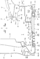
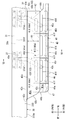
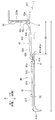
- FIG. 3 is a sectional view taken along line III-III in FIG. 1. It is sectional drawing of the vehicle which made the sliding door the closed state. It is a top view of a part of vehicle showing a part of step structure for vehicles.
- FIG. 6 is a schematic cross-sectional view of each step plate corresponding to the cross-sectional view taken along line VI-VI of FIG. 5.
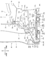
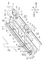
- It is a lower part perspective view of a vehicle showing a part of step structure for vehicles.
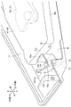
- It is a bottom view of a part of vehicle showing the mode of position displacement of the first step board.
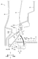
- It is a perspective view of a bracket and a rolling roller of a connecting mechanism.
- FIGS. 1 to 18 For the sake of convenience, in each drawing, arrow lines indicating the front-rear direction, the left-right direction, and the up-down direction of the vehicle are illustrated. Further, in the embodiments described below, the left-right direction of the vehicle is defined as the vehicle width direction, the left side of the vehicle is the vehicle width direction outer side (vehicle outer side), and the right side of the vehicle is the vehicle width direction inner side. In each figure, for convenience, the arrow indicating the direction of the vehicle may be referred to as left side (outside) and right side (inside).
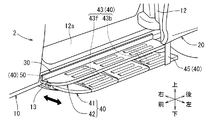
- the vehicle 2 shown in FIG. 1 includes a vehicle body 10 that forms the outer shape of the vehicle and a vehicle step structure 40. Further, the vehicle body 10 is provided with a front door opening 11 and a rear door opening 12.
- the front door opening 11 is an opening corresponding to a front seat such as a driver's seat or a passenger seat, and is configured to be openable/closable by a front door 15 rotatable about a door hinge (not shown).
- a rear door opening 12 (details described later) is an opening corresponding to a rear seat and is configured to be opened and closed by a slide door 20 (details described later) that slides in the vehicle front-rear direction.
- a step structure 40 for a vehicle is provided on the lower edge side of the rear door opening 12 (below the rocker 30 described below), as shown in FIG.
- the vehicle step structure 40 has, as main components, a first step plate 41 and a second step plate 42, which are treads, and a four-node link mechanism 43, which serves as a support mechanism. See below).
- the first step plate 41 is installed below the rocker 30 via the four-bar link mechanism 43, and can be further linked to the slide door 20 by the linking mechanism 45. Has become. That is, the first step plate 41 can be moved from the storage position to the use position by utilizing the force when the slide door 20 is opened.
- the present embodiment provides a vehicle step structure 40 that can release the interlocking between the first step plate 41 and the slide door 20 while ensuring excellent operability by using a latch portion 50 described later. did.
- each configuration will be described in detail.
- the rear door opening 12 shown in FIGS. 2 and 3 is a portion corresponding to the door opening of the present disclosure, and the fixed step plate 12s, the rocker 30, and the locker 30 are provided in the vehicle body 10 portion at the lower edge thereof.
- the rocker 30 is a tubular frame extending in the vehicle front-rear direction below the fixed step plate 12s, and has a support bracket 37 described later.
- the locker 30 includes a rocker inner 31, a rocker outer 330, and a side outer 35 that covers the upper left side of the rocker outer 330.
- the rocker inner 31 is a frame that extends in the vehicle front-rear direction, is formed in a substantially lateral U-shaped cross section, and is open on the left side (the vehicle width direction outer side). Flange portions 31u and 31d are formed at the upper end position and the lower end position of the rocker inner 31, respectively, and the floor panel 16 is fixed to the upper end corner portion of the rocker inner 31 by welding or the like in a state of being overlapped from above. ing.
- the rocker outer 330 shown in FIG. 3 is a plate-shaped member fitted into the rocker inner 31 from the left side.
- the rocker outer 330 is composed of an upper panel 331 having a substantially inverted L-shaped cross section, a plate-shaped ceiling panel 332 bent in a step shape, and a lower panel 333 having a substantially U-shaped horizontal cross-section.
- the upper panel 331 has a vertically oriented flange portion 331u formed at the upper end position and a horizontally oriented flange portion 331y formed at the lower end position.
- the vertical flange portion 331u at the upper end position is joined by welding or the like while being sandwiched between the flange portion 31u of the rocker inner 31 (upper end position) and the flange portion 35u of the side outer 35 (upper end position).
- a body-side weather strip 17 is fitted into each of the joined flange portions 35u, 331u, 31u.
- the body-side weather strip 17 allows the slide door 20 and a rear door opening portion of the vehicle body 10 to be described later.
- the left edge of the fixed step plate 12s is fixed to the upper portion of the body side weather strip 17, and the rocker inner 31 and the upper side of the floor panel 16 are covered by the fixed step plate 12s.
- An outer flange portion 332w of the ceiling panel 332 is joined to the lateral flange portion 331y of the upper panel 331 (lower end position) by welding or the like in a state of being overlapped from the lower side.
- the ceiling panel 332 is a panel that extends in the left-right direction while bending in a step shape, and the lower guide rail 19 is attached to the lower surface of the ceiling panel 332.
- the ceiling panel 332 is provided with a vertical wall portion 332t on the rear end side (right end side), and the vertical wall portion 332t is joined to the vertical wall portion of the rocker inner 31 by welding or the like.
- the lower panel 333 shown in FIG. 3 is formed in a substantially U-shaped cross section in a substantially horizontal direction, and on the left side thereof, a vertical mounting flange portion 333w for installing a second step plate 42 described later is provided.
- a vertical wall-shaped upper end flange portion 333u is formed at an upper end position on the right side (inside the vehicle width direction) of the lower panel 333, and a vertical wall-shaped lower end flange portion is also formed at a lower end position on the right side of the lower panel 333.
- the portion 333f is formed.
- the upper end flange portion 333u is joined to the vertical wall portion of the rocker inner 31 by welding or the like while being stacked on the vertical wall portion 332t of the ceiling panel 332.
- a space S1 is formed between the lower panel 333 and the ceiling panel 332, and a drive device (not shown) for the slide door 20 described later and the like are housed in the space S1 together with the lower guide rail 19 described above.
- the lower end flange portion 333f is overlapped with the flange portion 31d formed at the lower end position of the rocker inner 31 and joined by welding or the like.
- the lower end flange portion 333f of the lower panel 333 and the flange portion 31d of the rocker inner 31 will be referred to as lower end flange portions 333f and 31d of the rocker 30.
- a support bracket 37 is fixed to the lower side of the rocker 30.
- the support bracket 37 supports a four-node link mechanism 43 of a vehicle step mechanism 40 described later from below (of the four-node link mechanism 43).
- the connection mode will be described later).
- the support brackets 37 of this embodiment are used in pairs as shown in FIGS. 5 and 7. As shown in FIG. 3, each of these support brackets 37 is fixed to the rocker 30 by straddling the lower end flange portions 333f, 31d of the rocker 30 and on the left and right sides thereof. That is, each support bracket 37 includes a straddle portion 37m that straddles the lower end flange portions 333f and 31d, and an inner flange portion 37e provided inside the straddle portion 37m.
- each support bracket 37 has support portions 37sf and 37sb (details will be described later) arranged on the left side of the lower end flange portions 333f and 31d as shown in FIG. 7, and on both front and rear sides of these support portions 37sf and 37sb.
- support portions 37sf and 37sb are each provided with an outer flange portion 37f.
- the outer flange portion 37f of the support bracket 37 is bolted to the lower panel 333 of the rocker outer 330 from below.
- the lower panel 13 shown in FIG. 2 is a plate-shaped member disposed below the rocker 30, and has a substantially rectangular shape when viewed from above as shown in FIGS. 10 and 11.
- the lower panel 13 is arranged below the first step plate 41 at a storage position described later with an appropriate gap, and between the lower panel 13 and the first step plate 41, a first step plate 41 described later is provided.
- a gap is provided to allow the connecting work of the slide doors 20.
- the front and rear dimensions of the lower panel 13 are longer than the first step plate 41 in the storage position, and project from the lower side of the first step plate 41 toward the front. Further, the left and right dimensions of the lower panel 13 are set to dimensions capable of covering the entire width of the first step plate 41 at the storage position described later.
- the lower panel 13 is arranged substantially parallel to the surface direction of a first step plate 41 described later, and a support shaft 13a protruding upward is provided on the front side of the lower panel 13.
- the support shaft 13a is a clip member having a substantially cylindrical shape, and a barb is provided on the tip side thereof. Further, the support shaft 13a is structurally configured so as to be flexibly deformable inward in the radial direction, and a latch portion 50 described later is attached to the front side of the upper surface of the lower panel 13 via the support shaft 13a. Furthermore, a through hole 13H for a holding structure 55 shown in FIG.
- the slide door 20 shown in FIGS. 1 to 3 is a member having a hollow closed cross section, and a part of a connecting mechanism (a bracket 45b and a rolling roller 45r) described later is attached thereto.
- the sliding door 20 has an outer dimension capable of covering the rear door opening 12, and is configured by a door outer panel 22 and a door inner panel 23 joined together at their peripheral portions.
- an exterior material 24 extending in the vehicle front-rear direction is provided on the lower left portion of the door outer panel 22.
- the lower end portion of the exterior material 24 projects to the left side (outside in the vehicle width direction), and below it, there is provided a space in which step plates 41 and 42, a bracket 45b, and a rolling roller 45r can be arranged.
- step plates 41 and 42, a bracket 45b, and a rolling roller 45r can be arranged.
- a door side weather strip 23w capable of contacting the peripheral edge of the rear door opening 12 is provided.
- a guide roller unit is provided at each of the upper position, the center position in the height direction and the lower position of the door inner panel 23 shown in FIG. 4 (in FIG. 4, only the lower guide roller unit 25 is shown for convenience).
- a lower guide roller unit 25 is provided below the door inner panel 23, and the lower guide roller unit 25 is provided at a position higher than the door side weather strip 23w.
- a vertically oriented roller member (reference numeral omitted) is rotatably supported by the lower guide roller unit 25, and the roller member rolls on the lower guide rail 19 disposed in the space S1 of the rocker 30. It is fitted in a movable state.
- the roller members of the guide roller unit at the upper position and the central position are also rotatably fitted in the upper guide rail (not shown) and the central guide rail (not shown) of the vehicle body 10 shown in FIG. Has been.
- the lower guide rail 19 (and the upper guide rail and the central guide rail) shown in FIG. 3 has a planar shape so that the slide door 20 can move along the movement paths Do and Ds shown in FIG. .. Therefore, when the slide door 20 moves from the fully closed position to the half open position, the slide door 20 moves to the left (outward in the vehicle width direction) along the movement path Do and moves to the rear of the vehicle. When the slide door 20 moves from the half open position to the full open position, the slide door 20 moves rearward of the vehicle along the movement track Ds.
- the vehicle step structure 40 shown in FIGS. 1 to 4 is a structure for assisting an occupant's up-and-down movement, and includes a first step plate 41, a second step plate 42, and a four-bar linkage mechanism 43 (support mechanism).
- a connecting mechanism 45, a latch portion 50, and a holding mechanism 55 (see FIG. 14).
- a four-bar linkage 43 which will be described later, is installed on the lower side of the rocker 30 together with the first step plate 41, supported by each support bracket 37.
- the second step plate 42 described later is installed on the rocker 30 side so as to be located above the first step plate 41.
- the first step plate 41 is arranged on the left side (outside in the vehicle width direction) of the lower end flange portions 333f, 31d, and further at a height position higher than the lower end position (H1) of the lower end flange portions 333f, 31d. It is arranged.
- the first step plate 41 shown in FIGS. 5 to 7 is a plate-like member that becomes a tread surface when an occupant gets on and off, and corresponds to the step plate of the present disclosure.
- the first step plate 41 is supported by a four-node link mechanism 43 (support mechanism), which will be described later, substantially parallel to the rocker 30.
- the first step plate 41 is formed in a front and rear long strip plate shape, and has a first upper surface portion 41a to be a tread surface.
- the first upper surface portion 41a has a substantially rectangular shape when viewed from above, and a plurality of anti-slip portions 41X and a plurality of guide portions 41Y are provided to project upward.
- Each of the non-slip portions 41X is a vertical plate-shaped portion extending in the front-rear direction, and each of the anti-slip portions 41X has substantially the same shape and size.
- a plurality of anti-slip portions 41X (three in each figure) are provided in a row on the left and right on the first upper surface portion 41a, and the rows of the adjacent anti-slip portions 41X are appropriately arranged in the front-rear direction. It is arranged at intervals.
- Each of the guide portions 41Y shown in FIGS. 5 and 6 is a vertical plate-shaped portion that extends in the left-right direction, which is the position displacement direction of the first step plate 41 described later, and all the guide portions 41Y have substantially the same shape and the same size. It is said that.
- These guide portions 41Y are respectively arranged between the rows of the adjacent non-slip portions 41X, and in the first upper surface portion 41a of the present embodiment, the guide portions 41Y are arranged in a well-balanced manner in the front-rear direction. Is becoming Each guide portion 41Y extends so as to cross the row of each anti-slip portion 41X, and the vertical dimension is large so as to get over each anti-slip portion 41X. That is, with reference to FIG.
- each guide portion 41Y gradually inclines upward from the right end toward the left, and the anti-slip portion 41X arranged on the rightmost side is provided. It has an inner taper surface Y1 that can be overcome. Further, an upper end surface portion on the left side (outside in the vehicle width direction) from the apex of the inner taper surface Y1 is arranged above the remaining non-slip portion 41X, and the outer taper surface is gradually inclined downward toward the left end. It is Y2.
- the left edge 42d of the second step plate 42 described later is in contact with the upper end surface (Y1, Y2) of each guide portion 41Y, and the second step plate 42 has the upper end surface (Y1, Y2) of each guide portion 41Y. It is possible to relatively move left and right along Y2).
- the first upper surface portion 41a shown in FIG. 5 has a short front edge portion 41b and a rear edge portion 41c extending left and right, and a long left edge portion 41d extending front and rear, as a peripheral portion thereof. And a right edge portion 41e are provided.
- the front edge portion 41b extends substantially straight to the left and right, and the rear edge portion 41c is gradually inclined toward the left as it goes rearward.
- the left edge portion 41d is an edge portion on the left side (outside in the vehicle width direction) of the first step plate 41, and extends substantially linearly in the front-rear direction.
- the right edge portion 41e (described later in detail) is an edge portion on the right side (inside the vehicle width direction) of the first step plate 41.
- each peripheral edge portion is bent downward as appropriate, and a housing portion 47 (described later in detail) surrounded by an appropriate edge portion is provided on the front left side of the first step plate 41. ing.
- the right edge portion 41e of the first step plate 41 is provided with a general edge portion 411 and a concave portion 412 (separation portion 413).
- the general edge portion 411 is an edge portion that forms the right edge portion 41e excluding the recessed portion 412, and extends linearly in the front-rear direction so as to be substantially parallel to the left edge portion 41d.
- the recessed portion 412 is a portion formed by notching the first step plate 41 in a rectangular shape as viewed from above.
- the recessed position 412 is provided at a position corresponding to the front side support bracket 37 (front side support part 37sf) with the first step plate 41 at the storage position described later as a reference.
- the recessed portion 412 is recessed to the left side of the general edge portion 411, and the bottom edge of the recessed portion 412 is provided with a separation portion 413 that is substantially parallel to the right edge portion 41e. .. In the recessed position 412, there is no plate portion to be the tread surface when viewed from above, and a relatively large gap (non-step region 60) may occur between the separated portion 413 and the rocker 30 as described later. ..
- the four-node link mechanism 43 shown in FIGS. 5 and 7 is a mechanism corresponding to the support mechanism of the present disclosure, and the first step can be adjusted in a state where the protrusion amount of the first step plate 41 to the left side (vehicle outer side) can be adjusted.
- the plate 41 can be supported with respect to the rocker 30. That is, the four-node link mechanism 43 supports the first step plate 41 with respect to the rocker 30 so as to be movable between the storage position and the use position, and the protrusion amount of the first step plate 41 can be adjusted by the position displacement.
- the four-bar linkage mechanism 43 includes a front support link 43f and a rear support link 43b.
- the front support link 43f and the rear support link 43b are plate-shaped members having the same length, and are axially connected to the first step plate 41 and the rocker 30, respectively, as described later.
- the base end portion of the front support link 43f and the base end portion of the rear support link 43b shown in FIGS. 5 and 7 are axially connected to the rocker 30 side via corresponding support brackets 37, respectively. Since the support links 43f and 43b are substantially the same in their shaft couplings, the details will be described below by taking the front support link 43f as an example.
- the base end portion of the front support link 43f is axially connected to the front support bracket 37 having a hat cross-sectional shape in a side view. Further, the front support bracket 37 is provided with a front support portion 37sf projecting downward with respect to the lower surface (lower panel 333) of the rocker 30.
- the front end of the front support link 43f is superposed on the front support part 37sf from above, and is axially connected to the front support part 37sf by the front rotation center shaft 43c in a horizontally rotatable state. .. In this way, the front support link 43f is axially connected to the front support portion 37sf projecting downward, and is placed under the first step plate 41.
- the front end of the front support link 43f is axially connected to the lower surface of the front part of the first step plate 41 by a front end connecting shaft 43x in a horizontally rotatable state.
- the base end portion of the rear support link 43b shown in FIGS. 5 and 7 is also axially connected to the rear support portion 37sb of the rear support bracket 37. That is, the base end portion of the rear support link 43b is also overlapped with the rear support portion 37sb from above, and is axially connected to the rear support portion 37sb by the rear rotation center shaft 43e in a horizontally rotatable state. ing.
- the tip portion of the rear support link 43b is axially connected to the lower surface side of the rear portion of the first step plate 41 by a tip connecting shaft 43y so as to be horizontally rotatable.
- the distance between the front and rear tip connecting shafts 43x and 43y connected to the first step plate 41 is equal to the distance between the rotation center shafts 43c and 43e connected to the front and rear supporting portions 37sf and 37sb. It is set to a value equal to the distance.
- the front support link 43f and the rear support link 43b are formed to have the same size. Therefore, the front support link 43f and the rear support link 43b of the four-bar linkage 43 are horizontally rotated, so that the first step plate 41 moves along the arc locus S while being held parallel to the rocker 30 in plan view. To move along.
- both the support links 43f and 43b horizontally rotate about the rotation center shafts 43c and 43e to a position substantially parallel to the rocker 30 (right rotation limit position) (see a two-dot broken line portion in FIG. 8).
- the tip portions of both the support links 43f and 43b rotate to the right (inward in the vehicle width direction) about the rotation center shafts 43c and 43e, so that the first step plate 41 has the two-dot broken line in FIG.
- the locker 30 is placed in a storage position below the locker 30.
- both the support links 43f and 43b horizontally rotate about the rotation center shafts 43c and 43e to a position substantially perpendicular to the rocker 30 (left rotation limit position) (see the solid line portion in FIG. 8).
- the tip portions of both the support links 43f and 43b rotate leftward (outward in the vehicle width direction) about the rotation center shafts 43c and 43e, whereby the first step plate 41 is shown by the solid line in FIG.
- the locker 30 is disposed in the use position by protruding from the lower side to the left side.
- the second step plate 42 shown in FIGS. 4 to 7 is a plate-like member that serves as a tread surface when an occupant gets on and off, and is arranged above the first step plate 41. Is disposed on the locker 30 side.
- a fixed plate portion 42x is connected to the second step plate 42 via a hinge portion 42y so as to have a substantially inverted L-shaped cross section.
- the fixed plate portion 42x is formed in a longitudinal vertical wall shape in the front and rear, and is fixed to the mounting flange portion 333w of the lower panel 333 by a method such as fastening.
- the lower edge of the fixed plate portion 42x is arranged above the first step plate 41, and the second step plate 42 is connected via the hinge portion 42y.
- the hinge portion 42y is a hinge-shaped portion that connects the lower edge of the fixed plate portion 42x and the right portion (right edge 42e) of the second step plate 42.
- the left portion (left edge 42d) side of the second step plate 42 is vertically rotatable with respect to the fixed plate portion 42x about the axis A extending in the front-rear direction of the hinge portion 42y.
- the second step plate 42 shown in FIGS. 5 to 7 protrudes leftward (outward in the vehicle width direction) from the hinge portion 42y, and is supported by each guide portion 41Y of the first step plate 41 and is generally supported by the second step plate 42. They are arranged in parallel.
- the second step plate 42 is formed in the shape of a long strip in the front-rear direction and has a second upper surface portion 42a to be a tread surface.
- the second upper surface portion 42a has a substantially rectangular shape when viewed from above, and has front, rear, left, and right dimensions capable of covering the recessed portion 412 (the non-step region 60 described later) of the first upper surface portion 41a in the use position. ..
- the front-rear dimension of the second upper surface portion 42a of this embodiment is substantially the same as the front-rear dimension of the first upper surface portion 41a, and the left-right dimension of the second upper surface portion 42a is equal to or larger than the left-right dimension of the recessed portion 412. Is set to.
- the left and right dimensions of the second step plate 42 are smaller than those of the first upper surface portion 41a so that the second step plate 42 can be arranged between the slide door 20 and the rocker 30 in the closed state shown in FIG.
- the second upper surface portion 42a is provided with a plurality of upper anti-slip portions 42X in left and right rows, and the rows of the adjacent upper anti-slip portions 42X are adjacent to each other. They are arranged at appropriate intervals in the front-rear direction. Then, referring to FIG. 5, the second upper surface portion 42a also has a short front edge 42b and a rear edge 42c extending left and right, and a long left edge 42d extending forward and backward, as a peripheral portion thereof. And a right edge 42e are provided (the upper anti-skid portion is omitted in FIG. 5 for convenience).
- the front edge 42b is gradually curved toward the right side as it goes forward, and the rear edge 42c extends substantially straight to the left and right. Further, the left edge 42d and the right edge 42e extend substantially forward and backward in a straight line and are in parallel with each other.
- the left edge 42d is bent downward with respect to the second upper surface portion 42a as shown in FIG. 6, and the left edge 42d is the upper end surface (Y1, Y2) of each guide portion 41Y of the first step plate 41. ) Is in contact with.
- connection mechanism 45 shown in FIGS. 2 to 4 is a mechanism for connecting the first step plate 41 and the slide door 20.
- the connecting mechanism 45 includes a bracket 45b and a rolling roller 45r on the slide door 20 side, and a rail portion 46 on the first step plate 41 side.
- the bracket 45b has a fixed side plate part 45x, a movable side plate part 45y, and a hinge part 45z, as shown in FIGS. 9, 12, and 13.
- the fixed side plate portion 45x is formed in a vertically long strip plate shape, and is fastened and fixed to the lower side of the door inner panel 23 by a vertical wall portion 451 provided on the upper portion thereof.
- the portion (452) below the vertical wall portion 451 of the fixed side plate portion 45x is inclined to the left side (outside in the vehicle width direction) as it goes downward, and the hinge portion 45z is formed at the lower edge of the fixed side plate portion 45x.
- the movable side plate portion 45y is connected via the.
- the hinge portion 45z is a hinge-shaped portion that connects the lower edge of the fixed side plate portion 45x and the left edge of the movable side plate portion 45y, and has a vertically extending shaft pin AB.
- the movable side plate portion 45y is formed into a strip plate shape that can be extended rightward (inward in the vehicle width direction) from the hinge portion 45z, and the rolling roller 45r is rotatable on the right edge side of the movable side plate portion 45y. Is pivoted.
- the right side of the movable side plate portion 45y is rotatable up and down with respect to the fixed side plate portion 45x with the shaft pin AB of the hinge portion 45z as a base point, and further the urging force of the urging member TM attached to the shaft pin AB is applied. Is biased upwards.
- the rail portion 46 of the first step plate 41 shown in FIGS. 3 and 4 has an inverted U-shaped cross section.
- the movable side plate portion 45y of the bracket 45b moves upward from below with the hinge portion 45z as a base point, so that the rolling roller 45r provided on the movable side plate portion 45y is fitted to the rail portion 46 from below. That is, the first step plate 41 and the slide door 20 are connected via the bracket 45b of the connecting mechanism 45, the rolling roller 45r, and the rail portion 46.
- the rail portion 46 is formed on the left end side of the first step plate 41, and is arranged on the lower side and the right side (inside the vehicle width direction) of the exterior material 24 of the slide door 20.
- the rail portion 46 is composed of a front end bent portion 46a and a straight portion 46b, and the straight portion 46b moves forward and backward along the left end of the lower surface of the first step plate 41. It is formed so as to extend in the direction.
- the front end bent portion 46a is bent rightward with respect to the straight portion 46b at a predetermined angle.
- the left edge 46c of the front end bent portion 46a gradually protrudes to the right from the left edge portion 41d of the first step plate 41 in a state of protruding downward.
- the front end bent portion 46a is formed along a movement locus Do when the slide door 20 starts moving from the fully closed position in the opening direction.
- the linear portion 46b is formed so as to intersect the movement locus Do and be parallel to the movement locus Ds from the half-open position to the fully-open position of the slide door 20.
- a housing portion 47 is provided at the left front position of the front end bent portion 46a.
- the accommodating portion 47 is a substantially triangular portion whose lower portion is open, and is parallel to the left edge 46c, the left edge 41d, the front edge 41b, and the left edge 41d of the front end bent portion 46a. It is surrounded by an extending inner edge portion 46f.
- the accommodation portion 47 is a portion for accommodating a locking claw 51 of a latch portion 50, which will be described later with reference to FIG. 11, and the front edge portion 41 b has a notch shape so as to communicate the inside and outside of the accommodation portion 47.
- An insertion hole portion 48 is provided.
- the locking claws 51 of the latch portion 50 which will be described later, are disposed in the accommodation portion 47 through the insertion hole portion 48, and the inner wall portion (at least one of 46c, 41d, 41b, 46f) of the accommodation portion 47 shown in FIG. Will be locked in.
- the latch portion 50 shown in FIGS. 2, 10 and 11 is a portion that holds the first step plate 41 in the storage position on the vehicle body 10 side, and as described later, connects the first step plate 41 and the slide door 20. It has a function to cancel.
- the latch portion 50 is a hollow rectangular tubular member, and has a substantially triangular bottom wall portion 50a, a peripheral wall portion 50b protruding upward from the peripheral edge of the bottom wall portion 50a, and a locking claw 51 (blocking portion) described later. 52) and a part of the holding mechanism 55.
- an insertion hole (not shown) for the support shaft is provided at approximately the center of the bottom wall portion 50a.
- the support shaft 13a protruding from the upper surface of the lower panel 13 is inserted into the support shaft insertion hole of the bottom wall portion 50a, and the support shaft 13a is returned to prevent the support shaft 13a from coming off.
- the support shaft 13a is structurally reduced inward in the radial direction when it is inserted into the support shaft insertion hole, the support shaft 13a after insertion is appropriately expanded outward in the radial direction and is used for the support shaft. Is rotatably locked to the inner wall of the insertion hole.
- a plurality of leg portions 58 projecting downward are provided at appropriate positions on the bottom wall portion 50a, and the bottom wall portion 50a is in contact with the lower panel 13 via each leg portion 58. ..
- the latch part 50 is pivotally supported by a support shaft 13a on the front side of the upper surface of the lower panel 13, and is arranged in front of the first step plate 41.
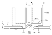
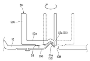
- the latch portion 50 can be displaced between a lock position locked by the first step plate 41 and an unlock position disengaged from the first step plate 41. It is said that.
- the latch portion 50 can be displaced to the lock position shown in FIG. 11 by rotating the latch part 50 from the unlock position shown in FIG.
- the latch part 50 rotates along the upper surface of the lower panel 13 which is substantially parallel to the first step plate 41, and moves from the direction along the surface direction of the first step plate 41 to the first step plate 41. It has a lockable structure.
- the latch portion 50 has a locking claw 51 that is locked to the first step plate 41 at the storage position in the locked position.
- the locking claw 51 is a vertical wall-shaped portion protruding from the peripheral wall portion 50b, and is brought to a state of protruding rearward by setting the latch portion 50 to the lock position.
- the locking claw 51 that protrudes rearward at the lock position is inserted into the insertion hole portion 48 of the front edge portion 41b of the first step plate 41 and is arranged in the accommodation portion 47. Further, the tip end side of the locking claw 51 in the same state is bent to the right and abuts against the inner wall portion of the housing portion 47 to be locked.
- the latch portion 50 is set to the lock position, and the locking claw 51 is locked to the inner wall portion of the housing portion 47, so that the first step plate 41 in the storage position is locked and held on the vehicle body 10 side.
- the latch part 50 is rotated around the axis of the support shaft 13a along the surface direction of the first step plate 41 to be displaced from the lock position of FIG. 11 to the unlock position of FIG.
- the locking claw 51 comes off from the insertion hole portion 48, and is further in a state of protruding leftward at the unlocked position.
- the latch portion 50 in the unlock position in this manner, the locking claw 51 is disengaged from the first step plate 41, and thus the first step plate 41 is in a state in which the position can be freely displaced.
- the locking claw 51 shown in FIG. 11 is provided with a blocking portion 52 that blocks the connection between the first step plate 41 and the slide door 20 when locked by the first step plate 41.
- the blocking portion 52 is formed by the lower edge portion of the locking claw 51 and can be stored in the storage portion 47 together with the locking claw 51 as shown in FIGS. 11 and 12 (in FIG. 12, For convenience, the blocking site is shown with a hatch).
- the blocking portion 52 in the housing portion 47 is arranged so as to project downward (outward) from the front end bent portion 46a, and is located in the middle of the movement trajectory of the right side (rolling roller 45r) of the bracket 45b at the time of connection. Will be placed. Then, as will be described later, the interlocking between the first step plate 41 and the slide door 20 can be released by blocking the fitting of the rail portion 46 and the rolling roller 45r at the blocking portion 52.
- the lower panel 13 (vehicle body) and the latch portion 50 can hold the latch portion 50 by selecting either the locked position or the unlocked position.
- a mechanism 55 is provided.
- the holding mechanism 55 is composed of a convex portion 55a of a leaf spring member 55b provided on the lower panel 13 and a pair of concave portions 57a and 57b provided on the latch portion 50.
- the plate spring member 55b shown in FIG. 14 is a plate member having a substantially rectangular shape when viewed from above, and the base end of the plate spring member 55b is fixed to the lower surface side of the lower panel 13 by a method such as fastening.
- the convex portion 55a is a portion where the tip of the leaf spring member 55b is bent and formed so as to form a convex triangle upward, and is inserted into the through hole 13H for the holding structure 55.
- the convex portion 55a protrudes upward from the upper surface portion around the support shaft 13a of the lower panel 13 and is arranged so that it can be fitted into any of the concave portions 57a and 57b of the latch portion 50 described later.
- the convex portion 55a can be pressed downward while bending the leaf spring member 55b by being pressed from above.
- the bottom wall portion 50a of the latch portion 50 is provided with a first concave portion 57a and a second concave portion 57b.
- the first concave portion 57a and the second concave portion 57b are portions corresponding to a pair of concave portions of the present disclosure, and are formed by partially bending and deforming the bottom wall portion 50a upward.
- the first concave portion 57a is provided in a part of the bottom wall portion 50a so that the convex portion 55a can be fitted in the unlocked position. Therefore, referring to FIGS.
- the latch part 50 is displaced to the lock position while the first step plate 41 is arranged at the storage position.
- the locking claw 51 is locked to the inner wall portion of the housing portion 47, and the first step plate 41 is locked and held on the rocker 30 side.
- the latch portion 50 is installed on the side surface of the vehicle (below the rear door opening portion) and is arranged at a position where it can be easily operated, and has a configuration particularly suitable for in-line assembly. Therefore, according to the present embodiment, the positionally fixed first step plate 41 and the slide door 20 can be smoothly connected, which contributes to improving the workability of the connecting work.
- the left edge portion 41d of the first step plate 41 is in a state of being arranged at a position that substantially coincides with the left edge 42d of the second step plate 42 in the vertical direction as shown in FIG. Therefore, almost the entire width of the first step plate 41 is accommodated under the lower panel 333 of the rocker 30 and the second step plate 42, and is in a state of being well stored.
- the rolling roller 45r of the bracket 45b is located at the front end portion of the front end bent portion 46a of the rail portion 46 with reference to FIGS. 7 (two-dotted line) and FIG.
- the first step plate 41 is provided between the rocker 30 and the support links 43f and 43b in the height direction (vertical direction) with reference to FIGS. 3, 4 and 8 (two-dotted line). It is possible to displace from the use position to the storage position in the state of being arranged in. That is, in this embodiment, the first step plate 41 can be displaced in the height direction while being compactly arranged between the support links 43f and 43b and the rocker 30.
- the first step plate 41 in the retracted position is referred to FIG. 4, FIG. 8 and FIG. 9 from the left side (outside in the vehicle width direction) while being overlapped with at least a part of each support link 43f, 43b from the upper side. It is arranged next to the front support portion 37sf (in FIG. 9, for convenience, the support link portion overlapping the first step plate is shown with a hatch). That is, the first step plate 41 at the retracted position is arranged adjacent to or close to the left side of the front support portion 37sf in a state of overlapping the support links 43f and 43b facing the front-rear direction from the upper side.
- the first step plate 41 is placed next to the front support portion 37sf so as to overlap the support links 43f and 43b from the upper side, so that the first step plate 41 is more compact than the case where these are individually housed. It is configured to contribute to storage.
- at least a part of the first step plate 41 overlaps the support links 43f, 43b and the front support portion 37sf in the height direction and the vehicle width direction.
- at least a part of the first step plate 41 in the retracted position overlaps the support links 43f and 43b in the height direction and the front support portion 37sf in the vehicle width direction, so that the first step plate 41 can be stored compactly. It is a structure that surely contributes. Therefore, in this embodiment, the storage space of the first step plate 41 on the lower side of the locker 30 can be made as compact as possible.
- the right edge portion 41e of the first step plate 41 shown in FIG. 8 is provided with a recessed portion 412 which is recessed so as to avoid the front support portion 37sf.
- the front support portion 37sf is arranged in a recessed position 412 from the right side (inside in the vehicle width direction) so as to be fitted (inclusive state).
- an appropriate gap is provided between the separated portion 413 of the recessed position 412 and the front support portion 37sf, and the interference between the first step plate 41 and the front support portion 37sf is avoided in this gap. Is becoming In this way, by avoiding the interference between the first step plate 41 at the storage position and the front support portion 37sf at the recessed position 412 as the interference avoiding structure, the configuration further contributes to compact storage of the first step plate 41. ..
- the first step plate 41 does not move and is held at the storage position.
- the rolling roller 45r on the sliding door 20 side reaches the linear portion 46b of the rail portion 46.
- the linear portion 46b of the rail portion 46 intersects with the movement locus Do when the slide door 20 starts moving from the fully closed position in the opening direction. Therefore, when the rolling roller 45r on the slide door 20 side reaches the linear portion 46b, the leftward (outward in the vehicle width direction) moving force of the slide door 20 is applied to the linear portion 46b of the rail portion 46 via the rolling roller 45r.
- the first step plate 41 is pressed to the left.
- the front support link 43f and the rear support link 43b of the four-node link mechanism 43 rotate left about the rotation center shafts 43c and 43e of the corresponding support portions 37sf and 37sb, and the first step plate 41 moves the rocker 30. Move horizontally to the left in parallel with. Then, the rolling roller 45r moves rearward in the linear portion 46b of the rail portion 46 in accordance with the movement of the slide door 20 in the opening direction (rearward direction).
- both support links 43f and 43b of the four-bar linkage 43 rotate to the left rotation limit position as shown in FIGS.
- the plate 41 moves horizontally to the use position. In this way, when the slide door 20 moves from the half-open position to the fully-open position, the movement locus Ds of the slide door 20 becomes parallel to the linear portion 46b of the rail portion 46, so that the rolling roller 45r moves to the linear portion 46b of the rail portion 46.
- the first step plate 41 is held in the use position even if it moves backward inside (see FIGS. 2 and 3 ).
- the first step plate 41 is returned to the retracted position by the operation opposite to the above operation.
- the left edge 42d of the second step plate 42 relatively moves while being pushed up gradually along the outer tapered surface Y2 of each guide portion 41Y, so as to get over each of the non-slip portions 41X of the first upper surface portion 41a. You can move. Then, the left edge 42d of the second step plate 42 reaches the inner tapered surface Y1 at the right end of each guide portion 41Y and descends, so that the second step plate 42 and the first step plate 41 in the use position. It will return to a substantially parallel state. In this way, in this embodiment, the first step plate 41 can be moved relative to the second step plate 42 without being disturbed by each of the antiskid portions 41X as much as possible.
- the second step plate 42 is moved along the upper end surface (Y1, Y2) of each guide portion 41Y. It can be moved up and down smoothly.
- each step plate in use position (formation of non-step area)
- the first step plate 41 is in a state of largely protruding toward the left side (outside in the vehicle width direction) of the rocker 30.
- the recessed portion 412 is exposed to the left side of the rocker 30, so that the recessed portion 412 is separated from the separated portion 413 in the vehicle width direction (left-right direction).
- a relatively large gap is provided between the locker 30 and the locker 30.
- a large gap between the separated portion 413 and the rocker 30 is a non-step area 60 having no portion that serves as a tread surface in the vertical direction.
- the first step plate 41 can be made to largely project, but in this type of configuration, excellent boarding/alighting performance should be ensured even if the non-step region 60 is formed.
- the second step plate 42 of the present embodiment is arranged on the rocker 30 so as to cover the non-step area 60 from the vertical direction as shown in FIGS. 5 to 7. That is, the second step plate 42 is in a state of being bridged between the separated portion 413 of the first step plate 41 and the rocker 30, and is in a state of covering the non-step region 60 from the upper side. In this way, in the present embodiment, the second step plate 42 is arranged so as to cover the non-step area 60 formed between the separated portion 413 at the use position and the rocker 30, so that excellent boarding/alighting performance is ensured. It is a contributing structure.
- the second upper surface portion 42a of the second step plate 42 is similar to the first upper surface portion 41a of the first step plate 41. It can be used more appropriately as a tread.
- the first step plate 41 is projected to the left side (outside in the vehicle width direction) of the second step plate 42 on the rocker 30 side as shown in FIG.
- the left edge 42d of the second upper surface portion 42a is arranged on the portion 41e side. Therefore, the first upper surface portion 41a and the second upper surface portion 42a can be used as a substantially continuous tread surface, and the left and right dimensions L1 of both the upper surface portions 41a, 42a to be the tread surface can be increased. There is.
- the first step plate 41 moves to the use position in association with the slide door 20 as shown in FIG. 7, so that the first step plate 41 largely protrudes to the left side (outside in the vehicle width direction) of the rocker 30. It becomes a state. Then, when the occupant gets on the vehicle, as shown in FIG. 16, the occupant can go up to the passenger compartment (fixed step plate 12s) from the ground GR through the first step plate 41 and the second step plate 42. Further, when the passenger dismounts, he/she can descend from the fixed step plate 12s to the ground GR via the first step plate 41 and the second step plate 42.
- the occupant can get on and off the ground GR through the step plates 41, 42 by the two-motion (2M) operation of the fixed step plate 12s or vice versa, and is particularly suitable for a small occupant having a small stride and a small vertical movement of the foot. It has a device configuration.
- the first step plate 41 is placed in the storage position even when the slide door 20 is opened. It is configured. In this type of configuration, it is desirable that the interlock between the first step plate 41 and the slide door 20 can be released while ensuring excellent operability.
- the lower panel 13 is provided with a latch portion 50 that is locked to the first step plate 41 in the storage position from the direction along the surface direction of the first step plate 41.
- the latch portion 50 has a blocking portion 52 that blocks the connection between the first step plate 41 in the locked state and the slide door 20.
- the first step plate 41 is arranged at the storage position, and further the latch portion 50 is displaced to the lock position.
- the latch part 50 can be displaced from the unlock position to the lock position by a simple operation of rotating around the axis of the support shaft 13a along the surface direction of the first step plate 41.
- the latch portion 50 When the position of the latch portion 50 is displaced, referring to FIGS. 14 and 15, the protrusion 55a comes off from the first concave portion 57a and the convex portion 55a moves to the second concave upper portion 57b. The mating is done.
- the latch portion 50 By fitting the convex portions 55a to the concave portions 57a and 57b, for example, the latch portion 50 can be displaced with a decent feeling, and the latch portion 50 can be stably held at each position.
- the latch portion 50 is displaced to the lock position of FIG. 11 and the locking claw 51 is locked to the inner wall portion of the housing portion 47, whereby the first step plate 41 in the storage position is held on the vehicle body 10 side. ..
- the blocking portion 52 of the locking claw 51 is arranged in the accommodation portion 47 so as to be close to the rail portion 46 and project downward (outward) from the left edge 46c of the front end bent portion 46a. It Therefore, even if the movable side plate portion 45y of the bracket 45b is moved from the lower side to the upper side in an attempt to connect the first step plate 41 and the slide door 20, the movement of the movable side plate portion 45y comes into contact with the blocking portion 52. Be blocked.
- the blocking portion 52 of the latch portion 50 can release the connection between the first step plate 41 and the slide door 20.
- the first step plate 41 can be placed in the storage position even when the slide door 20 is opened. .. Therefore, as shown in FIG. 17, the occupant can get on and off the vehicle from the ground GR in a one-motion (1M) operation of the passenger compartment (fixed step plate 12s) or vice versa.
- the bracket 45b in the unconnected state is arranged on the slide door 20 shown in FIG.
- the movable side plate portion 45y of the bracket 45b in this state has moved upward with the hinge portion 45z as a base point. Then, by rotating the movable side plate portion 45y upward together with the rolling roller 45r, these can be arranged inside the fixed side plate portion 45x in a beautiful and compact manner.
- the latch portion 50 and the blocking portion 52 are provided on the vehicle body (lower panel 13), and these are moved along the surface direction of the first step plate 41, so that the latch portion 50 is formed.
- the interlocking between the first step plate 41 and the slide door 20 can be released with a simple configuration in which the blocking portion 52 is brought into contact with the bracket 45b.
- the simple step of using the fitting of the convex portion 55a and the concave portions 57a and 57b enables stable switching between the interlocking and non-interlocking of the first step plate 41 and the slide door 20. be able to. Therefore, according to the present embodiment, it is possible to provide the vehicle step structure 40 capable of canceling the interlocking between the first step plate 41 and the slide door 20 while ensuring excellent operability.
- the configuration of the latch portion may be various configurations other than the above configuration.
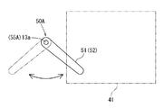
- the latch portion 50A of the modified example shown in FIG. 18 is configured by a plate member having a vertical wall shape, and a locking claw 51 and a blocking portion 52 are provided on the tip end side thereof.
- the modification is different from the embodiment in that a turnover spring 55A is used as a holding mechanism for the latch portion 50A. That is, in this modification, the base end side of the latch portion 50A is rotatably attached to the support shaft 13a of the lower panel via the turnover spring 55A as a holding mechanism. By doing so, the latch portion 50A is biased by the biasing force of the turnover spring 55A toward the lock position when approaching the lock position, and toward the unlock position when approaching the unlock position. Will be urged.
- the latch portion 50 at the unlocked position is in contact with a protrusion (not shown) provided on the lower panel.
- the vehicle step structure 40 of the present embodiment is not limited to the above-described embodiment, and various other embodiments can be adopted.
- the four-node link mechanism 43 is used as a support mechanism for the first step plate 41, and the first step plate 41 is moved from the storage position to the use position by the force of the sliding door 20 moving in the opening direction.
- the first step plate 41 is moved from the storage position to the use position by the force of the front door 15 (swing door) moving in the opening direction.
- first step plate and the second step plate can be provided with a plurality of or a single anti-slip portion, and the anti-slip portion can be omitted. Further, if the relative movement of the first step plate and the second step plate is possible, it is possible to omit part or all of the guide portion from the first step plate.
- the amount of protrusion of the first step plate can be changed as appropriate, but it is desirable to set so that all or part of the recessed portion protrudes from the vehicle body.
- the installation position of the vehicle step structure can also be set as appropriate, and the door opening on the rear side of the vehicle can be assumed in addition to the door opening on the side of the vehicle.
- the configuration (shape, size, arrangement position, constituent elements, etc.) of the latch section 50 is illustrated, but the configuration of the latch section is not limited.
- the latch portion may be arranged on the vehicle body via a rail or the like and slidably moved with respect to the first step plate.
- the locking claw of the latch portion may be brought into direct contact with the rolling roller.
- the installation position of the latch portion can be set to an appropriate position on the vehicle body in addition to the lower panel.
- the locking claw of the latch portion can be made to enter the rail portion (the front end bent portion or the straight portion), or can be brought into contact with the left edge portion of the first step plate.
- the holding mechanism can be composed of a convex portion provided on the latch portion and a pair of concave portions provided on the vehicle body. Further, the holding mechanism can be configured by a pair of convex portions and a concave portion. Further, the configuration of the connecting mechanism can be changed as appropriate.
- the fixed side plate part and the movable side plate part may be formed of a single plate spring material, and the rolling roller of the movable side plate part may be moved up and down by bending the plate spring material.
- the configuration (shape, size, arrangement position, etc.) of the second step plate 42 is illustrated, but the configuration of the second step plate is not limited.
- the second step plate of the first embodiment only needs to have a shape and dimensions that cover at least the recessed portion of the first step plate, may cover the non-step region from below, and ensures proper boarding/alighting performance. If possible, it is also permissible to leave a part of the non-step region in an uncovered state.
- the second step plate may be configured to move in conjunction with the support mechanism, and the second step plate may be omitted as appropriate.
- the recessed portion 412 of the first step plate 41 has been described as an example of the interference avoidance structure, but it is not intended to limit the configuration of the interference avoidance structure.
- the shape of the recessed portion can be changed according to the shape and size of the support portion, and in addition to the generally rectangular shape when viewed from above, various polygonal shapes, semicircular shapes, It may have various shapes such as a semi-elliptical shape.
- the right and left dimensions of the first step plate can be reduced so that the entire right edge portion thereof can be used as an interference avoiding structure.
- the interference avoiding structure can be omitted if necessary, and in this case, the first step plate and the supporting portion can be arranged adjacent to each other.
Landscapes
- Engineering & Computer Science (AREA)
- Mechanical Engineering (AREA)
- Vehicle Step Arrangements And Article Storage (AREA)
- Lock And Its Accessories (AREA)
- Braking Elements And Transmission Devices (AREA)
- Mechanical Control Devices (AREA)
Abstract
ステップ板(41)は、ドア開口部を開閉するドア(20)に連結されることにより、ドア(20)が開方向に移動するときの車両外側に向かう力を受けて格納位置から使用位置まで移動する構成であり、車両ボディには、ステップ板(41)の面方向に沿う向きから格納位置のステップ板(41)に係止されるラッチ部(50)が設けられており、ラッチ部(50)は、係止状態のステップ板(41)とドア(20)との連結を阻止する阻止部位(52)を有している。
Description
本開示は、車両ボディのドア開口部の位置に設けられる車両用ステップ構造に関する。
この種の車両用ステップ構造は、踏み面となるステップ板と、ステップ板を車幅方向等に動かす機構とを基本構成として有している。例えば特開2007‐55325号公報の車両用ステップ装置は、本開示のステップ板に相当する可動ステップと、四節リンクをなす一対のアーム部材とを有している。特開2007‐55325号公報の技術では、各アーム部材を電動で回動させることにより、可動ステップを、車両の床下下方に配置される格納位置と、車両の床下から車幅方向外側に突出する使用位置との間で変位させることができる。
ところで上述の車両用ステップ装置は、可動ステップを電動で動かしているため、省電力化の観点などから、すんなり採用できる構成ではなかった。そこで図19に示す実開平01‐83645号公報に開示の装置80は、前後方向にスライド移動可能なスライドドア81と、ステップ板に相当する昇降ステップ82とを有し、この昇降ステップ82とスライドドア81とが連動可能に係合されている。すなわち昇降ステップ82は、四節リンク構造83を介して車両ボディ90に連結されており、この四節リンク構造83には、スライドドア81側に係合可能なフック83aが設けられている。またスライドドア81の下縁には、左右方向(車幅方向)を向いた切換レバー84がピン85にて軸支されている。この切換レバー84は、ピン85を中心に回動可能であり、左右方向を向いた状態から前後方向を向いた状態に変位できる。そして切換レバー84の車幅方向内側(右側)に、四節リンク構造83のフック83aに係合する係止杆86が設けられ、切換レバー84の車幅方向外側(左側)に、スライドドア81の下方に突出する棒状の操作杆87が設けられている。
実開平01‐83645号公報の技術では、切換レバー84を左右方向に向けてフック83aと係止杆86を係合させることにより、昇降ステップ82を、スライドドア81に連動させることができる。例えばスライドドア81が開き方向(後方)に移動するときの力を利用して、四節リンク構造83を車幅方向外側に回動させることにより、昇降ステップ82を格納位置から使用位置に変位させることができる。また切換レバー84を、操作杆87を持ち手として前後方向を向くように回動させておく。こうすることでフック83aと係止杆86の係合を解除することができ、スライドドア81と昇降ステップ82が非連動状態となる。
ここで実開平01‐83645号公報に開示の装置80では、切換レバー84を適切に操作するなどして、昇降ステップ82(ステップ板)とスライドドア81の連動が勝手に解除されないように配慮すべきである。しかし実開平01‐83645号公報の切換レバー84は、スライドドア81に取付けられているとともに、スライドドア81から操作杆87が下方に突出しているため、この操作杆87に予期しないタイミングで外力がかかるといった事態が想定される。このため公知技術の構成では、操作杆87に外力がかからないように気使いしなければならず、切換レバー84の操作性に課題を有していた。したがって、改良された車両用ステップ構造が必要とされている。
本開示の第一側面によると、車両用ステップ構造は、車両ボディのドア開口部の位置に設けられる車両用ステップ構造であり、ステップ板と、ステップ板を格納位置と使用位置間で移動可能な状態で車両ボディに対して支持する支持機構とを備えている。そしてステップ板は、ドア開口部を開閉するドアに連結されることにより、ドアが開方向に移動するときの車両外側に向かう力を受けて格納位置から使用位置まで移動する構成である。本側面では、ステップ板の位置変位をドアに連動させるのであるが、この種の構成では、優れた操作性を確保しつつ、ステップ板とドアの連動を解除できることが望ましい。
そこで本側面の車両ボディには、ステップ板の面方向に沿う向きから格納位置のステップ板に係止されるラッチ部が設けられており、ラッチ部は、係止状態のステップ板とドアとの連結を阻止する阻止部位を有している。本側面では、ラッチ部と阻止部位を車両ボディに設け、さらにこれらをステップ板の面方向に沿って動かす構成としたことで、ラッチ部をドアに突設する場合に比して、優れた操作性の確保に資する構成となっている。
本開示の第二側面によると、車両用ステップ構造は、ステップ板とドアを連結する連結構造として、ドア側に設けられたブラケットに回転自在に取付けられた転動ローラと、ステップ板に設けられ且つ転動ローラが転動可能な状態で嵌合するレール部とを備えている。またラッチ部は、ステップ板に係止される係止爪と、係止爪に設けられた阻止部位とを有している。そして阻止部位は、係止爪からレール部の外方に突出して転動ローラ又はブラケットに当接することにより、転動ローラとレール部との嵌合を阻止する構成である。本側面では、転動ローラ又はブラケットに阻止部位を当接させるシンプルな構成にて、ステップ板とドアの連動を解除することが可能となっている。
本開示の第三側面によると、ラッチ部は、車両ボディに支軸を介して連結されているとともに、支軸を中心とするステップ板の面方向に沿った回動によって、ステップ板に係止されたロック位置と、ステップ板から係脱したアンロック位置との間で変位可能とされている。本側面では、ラッチ部を回動させる簡便な操作にて、ステップ板とドアの連動と非連動の切換を行うことができる。
本開示の第四側面によると、車両用ステップ構造は、ラッチ部をロック位置とアンロック位置で保持可能な保持機構を有している。そして保持機構は、車両ボディとラッチ部のいずれか一方に設けられた凸状部と、一方とは異なる他方に設けられた一対の凹状部とから構成され、一対の凹状部の一方には、ロック位置のラッチ部において凸状部が嵌合され、一対の凹状部の他方には、アンロック位置のラッチ部において凸状部が嵌合される。本側面では、凸状部と各凹状部の嵌合を利用したシンプルな構成にて、ステップ板とドアの連動と非連動の切換を安定的に行うことができる。
以下、本開示を実施するための形態を、図1~図18を参照して説明する。各図には、便宜上、車両の前後方向と左右方向と上下方向を示す矢線を図示する。また以下に示す実施例では、車両の左右方向が車幅方向と規定され、車両の左側が車幅方向外側(車両外側)となり、車両の右側が車幅方向内側となる。そして各図では、便宜上、車両の方向を示す矢線に、左側(外側)と表記し、右側(内側)と表記することがある。
図1に示す車両2は、車両の外形をなす車両ボディ10と、車両用ステップ構造40とを備え、さらに車両ボディ10には、フロントドア開口部11とリヤドア開口部12が設けられている。フロントドア開口部11は、運転席や助手席等の前部座席に対応する開口部であり、ドアヒンジ(図示省略)を中心に回動可能なフロントドア15により開閉可能に構成されている。またリヤドア開口部12(詳細後述)は、後部座席に対応する開口部であり、車両前後方向にスライドするスライドドア20(詳細後述)により開閉可能に構成されている。
[実施例1]
そしてリヤドア開口部12の下縁部側(後述のロッカー30の下側)には、図2に示すように車両用ステップ構造40が設けられている。この車両用ステップ構造40は、主構成として、踏み面となる第一ステップ板41及び第二ステップ板42と、支持機構としての四節リンク機構43とを有している(各構成の詳細は後述)。また車両用ステップ構造40では、第一ステップ板41が、四節リンク機構43を介してロッカー30の下側に設置され、さらに連結機構45にてスライドドア20に連動可能に連結することが可能となっている。すなわち第一ステップ板41は、スライドドア20が開く際の力を利用して格納位置から使用位置まで移動することが可能となっている。そして第一ステップ板41とスライドドア20の連動は、後述するようにラッチ部50の操作にて適宜解除されるのであるが、この種のラッチ部50は、優れた操作性を有していることが望ましい。そこで本実施例では、後述するラッチ部50を用いることで、優れた操作性を確保しつつ、第一ステップ板41とスライドドア20の連動を解除可能な車両用ステップ構造40を提供することとした。以下、各構成について詳述する。
そしてリヤドア開口部12の下縁部側(後述のロッカー30の下側)には、図2に示すように車両用ステップ構造40が設けられている。この車両用ステップ構造40は、主構成として、踏み面となる第一ステップ板41及び第二ステップ板42と、支持機構としての四節リンク機構43とを有している(各構成の詳細は後述)。また車両用ステップ構造40では、第一ステップ板41が、四節リンク機構43を介してロッカー30の下側に設置され、さらに連結機構45にてスライドドア20に連動可能に連結することが可能となっている。すなわち第一ステップ板41は、スライドドア20が開く際の力を利用して格納位置から使用位置まで移動することが可能となっている。そして第一ステップ板41とスライドドア20の連動は、後述するようにラッチ部50の操作にて適宜解除されるのであるが、この種のラッチ部50は、優れた操作性を有していることが望ましい。そこで本実施例では、後述するラッチ部50を用いることで、優れた操作性を確保しつつ、第一ステップ板41とスライドドア20の連動を解除可能な車両用ステップ構造40を提供することとした。以下、各構成について詳述する。
[ドア開口部]
ここで図2及び図3に示すリヤドア開口部12は、本開示のドア開口部に相当する部位であり、その下縁部の車両ボディ10部分には、固定ステップ板12sと、ロッカー30と、後述のロアパネル13とが設けられている。ここでロッカー30は、固定ステップ板12sの下方で車両前後方向に延びる筒状のフレームであり、後述する支持ブラケット37を有している。そしてロッカー30は、ロッカーインナー31と、ロッカーアウター330と、ロッカーアウター330の上部左側を覆うサイドアウター35とから構成されている。ロッカーインナー31は、車両前後方向に延びるフレームであって、断面略横向きU字形に形成されて左側(車幅方向外側)が解放されている。このロッカーインナー31の上端位置と下端位置とには、それぞれフランジ部31u,31dが形成され、ロッカーインナー31の上端角部には、フロアパネル16が上から重ねられた状態で溶接等により固定されている。
ここで図2及び図3に示すリヤドア開口部12は、本開示のドア開口部に相当する部位であり、その下縁部の車両ボディ10部分には、固定ステップ板12sと、ロッカー30と、後述のロアパネル13とが設けられている。ここでロッカー30は、固定ステップ板12sの下方で車両前後方向に延びる筒状のフレームであり、後述する支持ブラケット37を有している。そしてロッカー30は、ロッカーインナー31と、ロッカーアウター330と、ロッカーアウター330の上部左側を覆うサイドアウター35とから構成されている。ロッカーインナー31は、車両前後方向に延びるフレームであって、断面略横向きU字形に形成されて左側(車幅方向外側)が解放されている。このロッカーインナー31の上端位置と下端位置とには、それぞれフランジ部31u,31dが形成され、ロッカーインナー31の上端角部には、フロアパネル16が上から重ねられた状態で溶接等により固定されている。
また図3に示すロッカーアウター330は、ロッカーインナー31に対して左側から嵌込まれた板状部材である。このロッカーアウター330は、断面略逆L字形の上部パネル331と、段差状に屈曲した板状の天井パネル332と、断面略横向き逆U字形に形成された下部パネル333とから構成されている。上部パネル331は、上端位置に縦向きフランジ部331uが形成されており、下端位置に横向きフランジ部331yが形成されている。そして上端位置の縦向きフランジ部331uは、ロッカーインナー31(上端位置)のフランジ部31uとサイドアウター35(上端位置)のフランジ部35uとに挟まれた状態で溶接等により接合されている。また接合された各フランジ部35u,331u,31uには、ボディ側ウエザストリップ17が嵌め込まれており、このボディ側ウエザストリップ17にて、後述のスライドドア20と車両ボディ10のリヤドア開口部12間をシールできる。なおボディ側ウエザストリップ17の上部には固定ステップ板12sの左縁が固定されており、この固定ステップ板12sによって、ロッカーインナー31とフロアパネル16の上側が覆われている。また上部パネル331(下端位置)の横向きフランジ部331yには、天井パネル332の外部フランジ部332wが下側から重ねられた状態で溶接等により接合されている。この天井パネル332は、段差状に屈曲しつつ左右に延びるパネルであり、天井パネル332の下面には下部ガイドレール19が取付けられている。そして天井パネル332は、奥端側(右端側)に縦壁部332tが設けられており、この縦壁部332tがロッカーインナー31の縦壁部に溶接等により接合されている。
また図3に示す下部パネル333は、断面略横向き逆U字形に形成されており、その左側に、後述する第二ステップ板42設置用の縦向きの取付けフランジ部333wが設けられている。また下部パネル333の右側(車幅方向内側)の上端位置には、縦壁状の上端フランジ部333uが形成されており、下部パネル333の右側の下端位置には、同じく縦壁状の下端フランジ部333fが形成されている。上端フランジ部333uは、天井パネル332の縦壁部332tに重ねられた状態でロッカーインナー31の縦壁部に溶接等により接合されている。そして下部パネル333と天井パネル332の間に空間S1が形成され、この空間S1には、上述の下部ガイドレール19とともに、後述するスライドドア20の駆動装置(図示省略)等が収納される。また下端フランジ部333fは、ロッカーインナー31の下端位置に形成されたフランジ部31dに重ねられて溶接等で接合されている。以後、下部パネル333の下端フランジ部333fとロッカーインナー31のフランジ部31dとをロッカー30の下端フランジ部333f,31dと呼ぶことにする。
またロッカー30の下側には支持ブラケット37が固定されており、この支持ブラケット37によって、後述の車両用ステップ機構40の四節リンク機構43が下方から支持されている(四節リンク機構43の連結態様は後述)。そして本実施例の支持ブラケット37は、図5及び図7に示すように二個一組で使用されている。これら各支持ブラケット37は、図3に示すように、ロッカー30の下端フランジ部333f,31dを跨いでこれらの左側と右側とでロッカー30に固定されている。すなわち各支持ブラケット37は、下端フランジ部333f,31dを跨ぐ跨ぎ部37mと、跨ぎ部37mの内側に設けられた内側フランジ部37eとを備えている。そして支持ブラケット37の内側フランジ部37eが、図3に示すようにロッカーインナー31に対して下側からボルト止めされる。また各支持ブラケット37は、図7に示すように各下端フランジ部333f,31dの左側に配置される支持部37sf,37sb(詳細後述)を有し、これら各支持部37sf,37sbの前後両側には、それぞれ外側フランジ部37fが設けられている。そして支持ブラケット37の外側フランジ部37fが、ロッカーアウター330の下部パネル333に対して下側からボルト止めされる。
[ロアパネル]
そして図2に示すロアパネル13は、ロッカー30の下側に配設されている板状部材であり、図10及び図11に示すように上方視で概ね矩形状をなしている。このロアパネル13は、後述する格納位置の第一ステップ板41の下方に適宜の間隔をあけて配置されており、ロアパネル13と第一ステップ板41の間には、後述する第一ステップ板41とスライドドア20の連結作業を許容する隙が設けられている。そしてロアパネル13の前後の寸法は、格納位置の第一ステップ板41よりも長尺であり、第一ステップ板41の下方から前方に向けて突出している。またロアパネル13の左右の寸法は、後述する格納位置の第一ステップ板41の全幅を網羅可能な寸法に設定されている。そしてロアパネル13は、後述する第一ステップ板41の面方向に沿うように概ね平行に配置されており、ロアパネル13の前部側には、上方に突出する支軸13aが設けられている。この支軸13aは、概ね円筒形状をなすクリップ状の部材であって、その先端側に返しが設けられている。また支軸13aは、構造的に径方向内側に撓み変形可能な構成となっており、後述するラッチ部50が、支軸13aを介してロアパネル13の上面の前部側に取付けられている。さらにこの支軸13aの周囲のロアパネル13部分には、後述する図14の保持構造55用の貫通孔13Hが形成されている。
そして図2に示すロアパネル13は、ロッカー30の下側に配設されている板状部材であり、図10及び図11に示すように上方視で概ね矩形状をなしている。このロアパネル13は、後述する格納位置の第一ステップ板41の下方に適宜の間隔をあけて配置されており、ロアパネル13と第一ステップ板41の間には、後述する第一ステップ板41とスライドドア20の連結作業を許容する隙が設けられている。そしてロアパネル13の前後の寸法は、格納位置の第一ステップ板41よりも長尺であり、第一ステップ板41の下方から前方に向けて突出している。またロアパネル13の左右の寸法は、後述する格納位置の第一ステップ板41の全幅を網羅可能な寸法に設定されている。そしてロアパネル13は、後述する第一ステップ板41の面方向に沿うように概ね平行に配置されており、ロアパネル13の前部側には、上方に突出する支軸13aが設けられている。この支軸13aは、概ね円筒形状をなすクリップ状の部材であって、その先端側に返しが設けられている。また支軸13aは、構造的に径方向内側に撓み変形可能な構成となっており、後述するラッチ部50が、支軸13aを介してロアパネル13の上面の前部側に取付けられている。さらにこの支軸13aの周囲のロアパネル13部分には、後述する図14の保持構造55用の貫通孔13Hが形成されている。
[スライドドア]
図1~図3に示すスライドドア20は、中空閉断面状の部材であり、後述する連結機構の一部(ブラケット45b及び転動ローラ45r)が取付けられている。このスライドドア20は、リヤドア開口部12を被覆可能な外形寸法を有し、ドアアウタパネル22とドアインナパネル23とが互いの周縁部分で接合されて構成されている。さらにドアアウタパネル22の左下部には、車両前後方向に延びる外装材24が設けられている。この外装材24の下端部は、左側(車幅方向外側)に張り出しており、その下方に、後述の各ステップ板41,42とブラケット45bと転動ローラ45rを配置可能なスペースが設けられている。またドアインナパネル23の周縁近傍には、リヤドア開口部12の周縁に当接可能なドア側ウエザストリップ23wが設けられている。
図1~図3に示すスライドドア20は、中空閉断面状の部材であり、後述する連結機構の一部(ブラケット45b及び転動ローラ45r)が取付けられている。このスライドドア20は、リヤドア開口部12を被覆可能な外形寸法を有し、ドアアウタパネル22とドアインナパネル23とが互いの周縁部分で接合されて構成されている。さらにドアアウタパネル22の左下部には、車両前後方向に延びる外装材24が設けられている。この外装材24の下端部は、左側(車幅方向外側)に張り出しており、その下方に、後述の各ステップ板41,42とブラケット45bと転動ローラ45rを配置可能なスペースが設けられている。またドアインナパネル23の周縁近傍には、リヤドア開口部12の周縁に当接可能なドア側ウエザストリップ23wが設けられている。
また図4に示すドアインナパネル23の上部位置と高さ方向中央位置と下部位置にはそれぞれガイドローラーユニットが設けられている(図4では、便宜上、下部ガイドローラーユニット25のみ図示する)。例えばドアインナパネル23の下部には下部ガイドローラーユニット25が設けられており、この下部ガイドローラーユニット25は、ドア側ウエザストリップ23wよりも高い位置に設けられている。そして下部ガイドローラーユニット25には、縦向きのローラ部材(符号省略)が回転可能に軸支されており、このローラ部材が、ロッカー30の空間S1内に配置されている下部ガイドレール19に転動可能な状態で嵌め込まれている。なお図示しない上部位置と中央位置のガイドローラーユニットのローラ部材も、図1に示す車両ボディ10の上部ガイドレール(図示省略)と中央部ガイドレール(図示省略)とに転動可能な状態で嵌め込まれている。
ここで図3に示す下部ガイドレール19(及び上部ガイドレールと中央部ガイドレール)は、スライドドア20が図8に示す移動軌跡Do,Dsに沿って移動できるように平面形状が設定されている。このためスライドドア20が全閉位置から半開位置まで移動する際には、スライドドア20は移動軌跡Doに沿って左側(車幅方向外側)に移動しつつ車両後方に移動するようになる。そしてスライドドア20が半開位置から全開位置まで移動する際は、スライドドア20は移動軌跡Dsに沿って車両後方に移動するようになる。
[車両用ステップ構造]
図1~図4に示す車両用ステップ構造40は、乗員の昇降動作を支援するための構造であり、第一ステップ板41と、第二ステップ板42と、四節リンク機構43(支持機構)と、連結機構45と、ラッチ部50と、保持機構55とを備えている(図14参照)。本実施例では、後述する四節リンク機構43が、第一ステップ板41とともに、各支持ブラケット37に支持されてロッカー30の下側に設置されている。そして後述する第二ステップ板42は、第一ステップ板41の上側に位置するようにロッカー30側に設置されている。なお両ステップ板41,42の地上からの高さ位置(地上高)は、乗員の乗降動作を考慮して必要以上に高すぎないことが望ましい。ここでロッカー30の地上高は、地上の障害物などを考慮して適度な高さ位置に設定されている。そこで本実施例では、第一ステップ板41を、下端フランジ部333f,31dの左側(車幅方向外側)に配置し、さらに下端フランジ部333f,31dの下端位置(H1)以上の高さ位置に配置している。このように第一ステップ板41をロッカー30の下側に設置することで、第一ステップ板41の地上高が高くなりすぎるといった事態を極力回避しつつ、その地上高を適正値に設定できる。
図1~図4に示す車両用ステップ構造40は、乗員の昇降動作を支援するための構造であり、第一ステップ板41と、第二ステップ板42と、四節リンク機構43(支持機構)と、連結機構45と、ラッチ部50と、保持機構55とを備えている(図14参照)。本実施例では、後述する四節リンク機構43が、第一ステップ板41とともに、各支持ブラケット37に支持されてロッカー30の下側に設置されている。そして後述する第二ステップ板42は、第一ステップ板41の上側に位置するようにロッカー30側に設置されている。なお両ステップ板41,42の地上からの高さ位置(地上高)は、乗員の乗降動作を考慮して必要以上に高すぎないことが望ましい。ここでロッカー30の地上高は、地上の障害物などを考慮して適度な高さ位置に設定されている。そこで本実施例では、第一ステップ板41を、下端フランジ部333f,31dの左側(車幅方向外側)に配置し、さらに下端フランジ部333f,31dの下端位置(H1)以上の高さ位置に配置している。このように第一ステップ板41をロッカー30の下側に設置することで、第一ステップ板41の地上高が高くなりすぎるといった事態を極力回避しつつ、その地上高を適正値に設定できる。
[第一ステップ板(ステップ板)]
図5~図7に示す第一ステップ板41は、乗員の乗降の際に踏み面となる板状部材であり、本開示のステップ板に相当する。この第一ステップ板41は、後述の四節リンク機構43(支持機構)にて、ロッカー30に対して概ね平行に支持されている。そして第一ステップ板41は、前後に長尺な帯板状に形成されており、踏み面となるべき第一上面部41aを有している。この第一上面部41aは、上方視で概ね矩形状をなし、複数の滑止部41Xと、複数の案内部41Yとが上方に向けて突設されている。各滑止部41Xは、前後方向に延びる縦板状の部位であり、いずれの滑止部41Xも概ね同形同寸とされている。そして第一上面部41aには、複数の滑止部41X(各図では三つ)が左右に列をなして設けられており、隣り合う滑止部41Xの列同士は、前後方向に適宜の間隔をあけて配置されている。
図5~図7に示す第一ステップ板41は、乗員の乗降の際に踏み面となる板状部材であり、本開示のステップ板に相当する。この第一ステップ板41は、後述の四節リンク機構43(支持機構)にて、ロッカー30に対して概ね平行に支持されている。そして第一ステップ板41は、前後に長尺な帯板状に形成されており、踏み面となるべき第一上面部41aを有している。この第一上面部41aは、上方視で概ね矩形状をなし、複数の滑止部41Xと、複数の案内部41Yとが上方に向けて突設されている。各滑止部41Xは、前後方向に延びる縦板状の部位であり、いずれの滑止部41Xも概ね同形同寸とされている。そして第一上面部41aには、複数の滑止部41X(各図では三つ)が左右に列をなして設けられており、隣り合う滑止部41Xの列同士は、前後方向に適宜の間隔をあけて配置されている。
[案内部]
そして図5及び図6に示す各案内部41Yは、後述する第一ステップ板41の位置変位方向である左右方向に延びる縦板状の部位であり、いずれの案内部41Yも概ね同形同寸とされている。これら各案内部41Yは、隣り合う滑止部41Xの列の間にそれぞれ配置されており、本実施例の第一上面部41aでは、前後方向において各案内部41Yがバランスよく配置された状態となっている。そして各案内部41Yは、各滑止部41Xの列を横断するように延びているとともに、各滑止部41Xを乗り越えるように上下の寸法が大きくなっている。すなわち図6を参照して、各案内部41Yの右側(車幅方向内側)の上端面部分は、右端から左に向かうにつれて次第に上方に傾斜しており、最も右側に配置する滑止部41Xを乗り越えるような内側テーパ面Y1となっている。さらに内側テーパ面Y1の頂点から左側(車幅方向外側)の上端面部分は、残りの滑止部41Xの上方に配置されているとともに、左端に向かうにつれて次第に緩やかに下方に傾斜する外側テーパ面Y2となっている。そして各案内部41Yの上端面(Y1,Y2)には、後述する第二ステップ板42の左縁42dが接しており、この第二ステップ板42は、各案内部41Yの上端面(Y1,Y2)に沿って左右に相対移動することが可能となっている。
そして図5及び図6に示す各案内部41Yは、後述する第一ステップ板41の位置変位方向である左右方向に延びる縦板状の部位であり、いずれの案内部41Yも概ね同形同寸とされている。これら各案内部41Yは、隣り合う滑止部41Xの列の間にそれぞれ配置されており、本実施例の第一上面部41aでは、前後方向において各案内部41Yがバランスよく配置された状態となっている。そして各案内部41Yは、各滑止部41Xの列を横断するように延びているとともに、各滑止部41Xを乗り越えるように上下の寸法が大きくなっている。すなわち図6を参照して、各案内部41Yの右側(車幅方向内側)の上端面部分は、右端から左に向かうにつれて次第に上方に傾斜しており、最も右側に配置する滑止部41Xを乗り越えるような内側テーパ面Y1となっている。さらに内側テーパ面Y1の頂点から左側(車幅方向外側)の上端面部分は、残りの滑止部41Xの上方に配置されているとともに、左端に向かうにつれて次第に緩やかに下方に傾斜する外側テーパ面Y2となっている。そして各案内部41Yの上端面(Y1,Y2)には、後述する第二ステップ板42の左縁42dが接しており、この第二ステップ板42は、各案内部41Yの上端面(Y1,Y2)に沿って左右に相対移動することが可能となっている。
また図5に示す第一上面部41aには、その周縁をなす部分として、左右に延びている短尺な前縁部41b及び後縁部41cと、前後に延びている長尺な左縁部41d及び右縁部41eとが設けられている。前縁部41bは、概ね左右に直線的に延び、後縁部41cは、後方に向かうにつれて次第に左方に向けて傾斜している。また左縁部41dは、第一ステップ板41の左側(車幅方向外側)の縁部分であり、概ね前後に直線的に延びている。また右縁部41e(詳細後述)は、第一ステップ板41の右側(車幅方向内側)の縁部分である。そして本実施例では、各周縁部分が下方に向けて適宜屈曲しており、第一ステップ板41の前部左側には、適宜の縁部で囲まれた収容部位47(詳細後述)が設けられている。
[離間部位]
この第一ステップ板41の右縁部41eには、図5に示すように、一般縁部位411と、凹部位412(離間部位413)とが設けられている。一般縁部位411は、凹部位412を除く右縁部41eをなしている縁部分であり、左縁部41dと概ね並行となるように前後に直線的に延びている。また凹部位412は、第一ステップ板41を上方視で矩形状に切欠くことで形成されている部位である。この凹部位412は、後述する格納位置の第一ステップ板41を基準として、前側の支持ブラケット37(前側支持部37sf)と対応する位置に設けられている。そして凹部位412は、一般縁部位411に比して左側に凹んだ状態となっており、この凹部位412の底縁には、右縁部41eと概ね平行な離間部位413が設けられている。そして凹部位412では、上方視において踏み面となるべき板部分が存在せず、後述するように離間部位413とロッカー30との間に比較的大きな隙(非ステップ領域60)が生じることがある。
この第一ステップ板41の右縁部41eには、図5に示すように、一般縁部位411と、凹部位412(離間部位413)とが設けられている。一般縁部位411は、凹部位412を除く右縁部41eをなしている縁部分であり、左縁部41dと概ね並行となるように前後に直線的に延びている。また凹部位412は、第一ステップ板41を上方視で矩形状に切欠くことで形成されている部位である。この凹部位412は、後述する格納位置の第一ステップ板41を基準として、前側の支持ブラケット37(前側支持部37sf)と対応する位置に設けられている。そして凹部位412は、一般縁部位411に比して左側に凹んだ状態となっており、この凹部位412の底縁には、右縁部41eと概ね平行な離間部位413が設けられている。そして凹部位412では、上方視において踏み面となるべき板部分が存在せず、後述するように離間部位413とロッカー30との間に比較的大きな隙(非ステップ領域60)が生じることがある。
[四節リンク機構(支持機構)]
図5及び図7に示す四節リンク機構43は、本開示の支持機構に相当する機構であり、第一ステップ板41の左側(車両外側)への突出量を調整可能な状態で第一ステップ板41をロッカー30に対して支持することができる。すなわち四節リンク機構43は、ロッカー30に対して第一ステップ板41を格納位置と使用位置間で移動可能に支持しており、第一ステップ板41の突出量をその位置変位によって調整できる。この四節リンク機構43は、前支持リンク43f及び後支持リンク43bを備えている。これら前支持リンク43fと後支持リンク43bとは、等しい長さで形成された板状部材であり、後述するように第一ステップ板41とロッカー30とにそれぞれ軸連結されている。
図5及び図7に示す四節リンク機構43は、本開示の支持機構に相当する機構であり、第一ステップ板41の左側(車両外側)への突出量を調整可能な状態で第一ステップ板41をロッカー30に対して支持することができる。すなわち四節リンク機構43は、ロッカー30に対して第一ステップ板41を格納位置と使用位置間で移動可能に支持しており、第一ステップ板41の突出量をその位置変位によって調整できる。この四節リンク機構43は、前支持リンク43f及び後支持リンク43bを備えている。これら前支持リンク43fと後支持リンク43bとは、等しい長さで形成された板状部材であり、後述するように第一ステップ板41とロッカー30とにそれぞれ軸連結されている。
[支持部]
そして図5及び図7に示す前支持リンク43fの基端部と後支持リンク43bの基端部とは、それぞれ対応する支持ブラケット37を介してロッカー30側に軸連結されている。ここで各支持リンク43f,43bの軸連結の態様は概ね同一であるため、以下に、専ら前支持リンク43fを一例にその詳細を説明する。前支持リンク43fの基端部は、側面視でハット断面形状を有する前側の支持ブラケット37に軸連結される。また前側の支持ブラケット37には、ロッカー30の下面(下部パネル333)に対して下方に突出している前側支持部37sfが設けられている。そして前支持リンク43fの基端部は、前側支持部37sfに上から重ねられた状態とされて、前側の回転中心軸43cにより前側支持部37sfに水平回動可能な状態で軸連結している。こうして前支持リンク43fは、下方に突出している前側支持部37sfに軸連結されて、第一ステップ板41の下方に配置された状態となっている。そして前支持リンク43fの先端部は、第一ステップ板41の前部の下面側に先端連結軸43xによって水平回動可能な状態で軸連結されている。
そして図5及び図7に示す前支持リンク43fの基端部と後支持リンク43bの基端部とは、それぞれ対応する支持ブラケット37を介してロッカー30側に軸連結されている。ここで各支持リンク43f,43bの軸連結の態様は概ね同一であるため、以下に、専ら前支持リンク43fを一例にその詳細を説明する。前支持リンク43fの基端部は、側面視でハット断面形状を有する前側の支持ブラケット37に軸連結される。また前側の支持ブラケット37には、ロッカー30の下面(下部パネル333)に対して下方に突出している前側支持部37sfが設けられている。そして前支持リンク43fの基端部は、前側支持部37sfに上から重ねられた状態とされて、前側の回転中心軸43cにより前側支持部37sfに水平回動可能な状態で軸連結している。こうして前支持リンク43fは、下方に突出している前側支持部37sfに軸連結されて、第一ステップ板41の下方に配置された状態となっている。そして前支持リンク43fの先端部は、第一ステップ板41の前部の下面側に先端連結軸43xによって水平回動可能な状態で軸連結されている。
また図5及び図7に示す後支持リンク43bの基端部も、後側の支持ブラケット37の後側支持部37sbに軸連結されている。すなわち後支持リンク43bの基端部も後側支持部37sbに上から重ねられた状態とされて、後側の回転中心軸43eにより後側支持部37sbに水平回動可能な状態で軸連結している。そして後支持リンク43bの先端部は、第一ステップ板41の後部の下面側に先端連結軸43yによって水平回動可能な状態で軸連結されている。
[四節リンク機構による第一ステップ板の位置変位]
ここで図8を参照して、第一ステップ板41に連結された前後の先端連結軸43x,43y間の距離は、前後の支持部37sf,37sbに連結された回転中心軸43c,43e間の距離と等しい値に設定されている。また前支持リンク43fと後支持リンク43bとは等しい寸法で形成されている。このため四節リンク機構43の前支持リンク43fと後支持リンク43bとが水平回動することで、第一ステップ板41は、平面視においてロッカー30と平行に保持された状態で円弧軌跡Sに沿って移動するようになる。そして両支持リンク43f,43bの先端部が、回転中心軸43c,43eを中心にロッカー30とほぼ平行な位置(右回動限位置)まで水平回動する(図8の二点破線部分を参照)。このように両支持リンク43f,43bの先端部が、回転中心軸43c,43eを中心に右側(車幅方向内側)に回動することで、第一ステップ板41は、図8の二点破線で示すようにロッカー30の下側に位置する格納位置に配置される。また両支持リンク43f,43bの先端部が、回転中心軸43c,43eを中心にロッカー30とほぼ直角な位置(左回動限位置)まで水平回動する(図8の実線部分を参照)。このように両支持リンク43f,43bの先端部が、回転中心軸43c,43eを中心に左側(車幅方向外側)に回動することで、第一ステップ板41は、図8の実線で示すようにロッカー30の下側から左側に突出して使用位置に配置される。
ここで図8を参照して、第一ステップ板41に連結された前後の先端連結軸43x,43y間の距離は、前後の支持部37sf,37sbに連結された回転中心軸43c,43e間の距離と等しい値に設定されている。また前支持リンク43fと後支持リンク43bとは等しい寸法で形成されている。このため四節リンク機構43の前支持リンク43fと後支持リンク43bとが水平回動することで、第一ステップ板41は、平面視においてロッカー30と平行に保持された状態で円弧軌跡Sに沿って移動するようになる。そして両支持リンク43f,43bの先端部が、回転中心軸43c,43eを中心にロッカー30とほぼ平行な位置(右回動限位置)まで水平回動する(図8の二点破線部分を参照)。このように両支持リンク43f,43bの先端部が、回転中心軸43c,43eを中心に右側(車幅方向内側)に回動することで、第一ステップ板41は、図8の二点破線で示すようにロッカー30の下側に位置する格納位置に配置される。また両支持リンク43f,43bの先端部が、回転中心軸43c,43eを中心にロッカー30とほぼ直角な位置(左回動限位置)まで水平回動する(図8の実線部分を参照)。このように両支持リンク43f,43bの先端部が、回転中心軸43c,43eを中心に左側(車幅方向外側)に回動することで、第一ステップ板41は、図8の実線で示すようにロッカー30の下側から左側に突出して使用位置に配置される。
[第二ステップ板]
図4~図7に示す第二ステップ板42は、第一ステップ板41と同様に乗員の乗降の際に踏み面となる板状部材であり、第一ステップ板41の上側に配置されるようにロッカー30側に配設されている。この第二ステップ板42には、断面視略逆L字状となるように、固定板部42xがヒンジ部42yを介して連結されている。固定板部42xは、前後に長尺な縦壁状に形成されており、下部パネル333の取付けフランジ部333wに締結等の手法で固定されている。そして固定板部42xの下縁は、第一ステップ板41の上側に配置されているとともに、ヒンジ部42yを介して第二ステップ板42が連結されている。このヒンジ部42yは、固定板部42xの下縁と第二ステップ板42の右部分(右縁42e)とを連結する蝶番状の部位である。そして第二ステップ板42の左部分(左縁42d)側は、ヒンジ部42yの前後に延びる軸Aを中心として固定板部42xに対して上下に回動可能な状態となっている。
図4~図7に示す第二ステップ板42は、第一ステップ板41と同様に乗員の乗降の際に踏み面となる板状部材であり、第一ステップ板41の上側に配置されるようにロッカー30側に配設されている。この第二ステップ板42には、断面視略逆L字状となるように、固定板部42xがヒンジ部42yを介して連結されている。固定板部42xは、前後に長尺な縦壁状に形成されており、下部パネル333の取付けフランジ部333wに締結等の手法で固定されている。そして固定板部42xの下縁は、第一ステップ板41の上側に配置されているとともに、ヒンジ部42yを介して第二ステップ板42が連結されている。このヒンジ部42yは、固定板部42xの下縁と第二ステップ板42の右部分(右縁42e)とを連結する蝶番状の部位である。そして第二ステップ板42の左部分(左縁42d)側は、ヒンジ部42yの前後に延びる軸Aを中心として固定板部42xに対して上下に回動可能な状態となっている。
そして図5~図7に示す第二ステップ板42は、ヒンジ部42yから左側(車幅方向外側)に突出しているとともに、第一ステップ板41の各案内部41Yに下支えされて同板と概ね平行に配置されている。この第二ステップ板42は、前後に長尺な帯板状に形成されており、踏み面となるべき第二上面部42aを有している。この第二上面部42aは、上方視で概ね矩形状をなし、使用位置における第一上面部41aの凹部位412(後述の非ステップ領域60)を被覆可能な前後左右の寸法を有している。例えば本実施例の第二上面部42aの前後の寸法は、第一上面部41aの前後の寸法と概ね一致し、また第二上面部42aの左右の寸法は、凹部位412の左右の寸法以上に設定されている。なお第二ステップ板42の左右の寸法は、図4に示す閉じ状態のスライドドア20とロッカー30の間に配置可能なように第一上面部41aよりも小さくされている。
また図2及び図6を参照して、第二上面部42aには、複数の上側滑止部42Xが左右に列をなして設けられており、隣り合う上側滑止部42Xの列同士は、前後方向に適宜の間隔をあけて配置されている。そして図5を参照して、第二上面部42aにも、その周縁をなす部分として、左右に延びている短尺な前縁42b及び後縁42cと、前後に延びている長尺な左縁42d及び右縁42eとが設けられている(図5では、便宜上、上側滑止部を省略している)。前縁42bは、前方に向かうにつれて次第に右側に向けて湾曲しており、後縁42cは、概ね左右に直線的に延びている。また左縁42dと右縁42eとは、概ね前後に直線的に延びており互いに平行な状態となっている。そして左縁42dは、図6に示すように第二上面部42aに対して下方に屈曲しており、この左縁42dが、第一ステップ板41の各案内部41Yの上端面(Y1,Y2)に当接している。
[連結機構(ブラケット及び転動ローラ)]
図2~図4に示す連結機構45は、第一ステップ板41とスライドドア20とを連結する機構である。この連結機構45は、スライドドア20側のブラケット45b及び転動ローラ45rと、第一ステップ板41側のレール部46とから構成されている。ここでブラケット45bは、図9、図12及び図13に示すように、固定側板部45xと、可動側板部45yと、ヒンジ部位45zとを有している。固定側板部45xは、上下に長い帯板状に形成されており、その上部に設けられた縦壁部分451にて、ドアインナパネル23の下側に締結固定されている。この固定側板部45xの縦壁部分451から下の部分(452)は、下方に向かうにつれて左側(車幅方向外側)に傾斜しており、固定側板部45xの下縁には、ヒンジ部位45zを介して可動側板部45yが連結されている。このヒンジ部位45zは、固定側板部45xの下縁と可動側板部45yの左縁とを連結する蝶番状の部位であり、上下に延びている軸ピンABを有している。そして可動側板部45yは、ヒンジ部位45zから右側(車幅方向内側)に延長可能な帯板状に形成されており、可動側板部45yの右縁側には、転動ローラ45rが回転自在とされて軸支されている。そして可動側板部45yの右側は、ヒンジ部位45zの軸ピンABを基点に固定側板部45xに対して上下に回動可能とされ、さらに軸ピンABに取付けられた付勢材TMの付勢力にて上方に向けて付勢されている。
図2~図4に示す連結機構45は、第一ステップ板41とスライドドア20とを連結する機構である。この連結機構45は、スライドドア20側のブラケット45b及び転動ローラ45rと、第一ステップ板41側のレール部46とから構成されている。ここでブラケット45bは、図9、図12及び図13に示すように、固定側板部45xと、可動側板部45yと、ヒンジ部位45zとを有している。固定側板部45xは、上下に長い帯板状に形成されており、その上部に設けられた縦壁部分451にて、ドアインナパネル23の下側に締結固定されている。この固定側板部45xの縦壁部分451から下の部分(452)は、下方に向かうにつれて左側(車幅方向外側)に傾斜しており、固定側板部45xの下縁には、ヒンジ部位45zを介して可動側板部45yが連結されている。このヒンジ部位45zは、固定側板部45xの下縁と可動側板部45yの左縁とを連結する蝶番状の部位であり、上下に延びている軸ピンABを有している。そして可動側板部45yは、ヒンジ部位45zから右側(車幅方向内側)に延長可能な帯板状に形成されており、可動側板部45yの右縁側には、転動ローラ45rが回転自在とされて軸支されている。そして可動側板部45yの右側は、ヒンジ部位45zの軸ピンABを基点に固定側板部45xに対して上下に回動可能とされ、さらに軸ピンABに取付けられた付勢材TMの付勢力にて上方に向けて付勢されている。
[レール部]
また図3及び図4に示す第一ステップ板41のレール部46は、断面形状が逆U字形に形成されている。そしてブラケット45bの可動側板部45yがヒンジ部位45zを基点に下方から上方に移動することで、この可動側板部45yに設けられた転動ローラ45rが下方からレール部46に嵌合している。すなわち第一ステップ板41とスライドドア20とは、連結機構45のブラケット45b、転動ローラ45r及びレール部46を介して連結されている。このレール部46は、第一ステップ板41の左端側に形成されて、スライドドア20の外装材24の下側且つ右側(車幅方向内側)に配置されている。
また図3及び図4に示す第一ステップ板41のレール部46は、断面形状が逆U字形に形成されている。そしてブラケット45bの可動側板部45yがヒンジ部位45zを基点に下方から上方に移動することで、この可動側板部45yに設けられた転動ローラ45rが下方からレール部46に嵌合している。すなわち第一ステップ板41とスライドドア20とは、連結機構45のブラケット45b、転動ローラ45r及びレール部46を介して連結されている。このレール部46は、第一ステップ板41の左端側に形成されて、スライドドア20の外装材24の下側且つ右側(車幅方向内側)に配置されている。
そしてレール部46は、図7及び図8に示すように、前端折曲部46aと直線部46bとから構成されており、直線部46bが、第一ステップ板41の下面の左端に沿って前後方向に延びるように形成されている。また前端折曲部46aは、直線部46bに対して右側に所定角度で折り曲げられている。この前端折曲部46aの左縁46cは、下方に向けて突出した状態で、前方に向かうにつれて次第に第一ステップ板41の左縁部41dから右方に離れていく。そして図8を参照して、前端折曲部46aは、スライドドア20が全閉位置から開方向に移動を開始するときの移動軌跡Doに沿うように形成されている。また直線部46bは移動軌跡Doとは交差し、スライドドア20の半開位置から全開位置までの移動軌跡Dsとは平行になるように形成されている。
[収容部位]
ここで図7を参照して、第一ステップ板41の前部下面側には、前端折曲部46aの左前位置に収容部位47が設けられている。収容部位47は、下方が解放状とされた概ね三角形状の部位であり、前端折曲部46aの左縁46cと、左縁部41dと、前縁部41bと、左縁部41dと平行に延びる内側縁部46fで囲まれている。この収容部位47は、図11を参照して、後述するラッチ部50の係止爪51を収容する部分であり、前縁部41bには、収容部位47の内外を連通するように切欠き状の挿入孔部48が設けられている。そして後述するラッチ部50の係止爪51は、挿入孔部48を通じて収容部位47内に配置されて、図7に示す収容部位47の内壁部分(46c,41d,41b,46fの少なくとも一つ)に係止されることとなる。
ここで図7を参照して、第一ステップ板41の前部下面側には、前端折曲部46aの左前位置に収容部位47が設けられている。収容部位47は、下方が解放状とされた概ね三角形状の部位であり、前端折曲部46aの左縁46cと、左縁部41dと、前縁部41bと、左縁部41dと平行に延びる内側縁部46fで囲まれている。この収容部位47は、図11を参照して、後述するラッチ部50の係止爪51を収容する部分であり、前縁部41bには、収容部位47の内外を連通するように切欠き状の挿入孔部48が設けられている。そして後述するラッチ部50の係止爪51は、挿入孔部48を通じて収容部位47内に配置されて、図7に示す収容部位47の内壁部分(46c,41d,41b,46fの少なくとも一つ)に係止されることとなる。
[ラッチ部]
図2、図10及び図11に示すラッチ部50は、格納位置の第一ステップ板41を車両ボディ10側に保持する部位であり、後述するように第一ステップ板41とスライドドア20の連結を解除する機能を有している。このラッチ部50は、中空角筒状の部材であり、概ね三角形状の底壁部50aと、底壁部50aの周縁から上方に突出する周壁部50bと、後述する係止爪51(阻止部位52)と保持機構55の一部を有している。ここで底壁部50aの概ね中央には支軸用の挿設孔(図示省略)が設けられている。そして底壁部50aの支軸用の挿設孔には、ロアパネル13の上面から突出している支軸13aが挿通され、さらに支軸13aの返しによって抜け止めがなされている。なお支軸用の挿設孔に挿入される際の支軸13aは構造的に径方向内側に縮小しているが、挿通後の支軸13aは、適度に径方向外側に拡がって支軸用の挿設孔の内壁に回転可能な状態で係止されている。なお底壁部50aには、図14に示すように、下方に突出する複数の脚部58が適宜の位置に設けられ、底壁部50aが各脚部58を介してロアパネル13に接している。
図2、図10及び図11に示すラッチ部50は、格納位置の第一ステップ板41を車両ボディ10側に保持する部位であり、後述するように第一ステップ板41とスライドドア20の連結を解除する機能を有している。このラッチ部50は、中空角筒状の部材であり、概ね三角形状の底壁部50aと、底壁部50aの周縁から上方に突出する周壁部50bと、後述する係止爪51(阻止部位52)と保持機構55の一部を有している。ここで底壁部50aの概ね中央には支軸用の挿設孔(図示省略)が設けられている。そして底壁部50aの支軸用の挿設孔には、ロアパネル13の上面から突出している支軸13aが挿通され、さらに支軸13aの返しによって抜け止めがなされている。なお支軸用の挿設孔に挿入される際の支軸13aは構造的に径方向内側に縮小しているが、挿通後の支軸13aは、適度に径方向外側に拡がって支軸用の挿設孔の内壁に回転可能な状態で係止されている。なお底壁部50aには、図14に示すように、下方に突出する複数の脚部58が適宜の位置に設けられ、底壁部50aが各脚部58を介してロアパネル13に接している。
そしてラッチ部50は、図10に示すようにロアパネル13の上面の前部側の支軸13aにて軸支されて、第一ステップ板41の前方に配置されている。このラッチ部50は、支軸13aの軸線周りに回転することで、第一ステップ板41に係止されるロック位置と、第一ステップ板41から係脱するアンロック位置との間で変位可能とされている。本実施例においては、ラッチ部50を、図10に示すアンロック位置から支軸13a回りに概ね90゜時計回りに半回転させることで図11に示すロック位置に変位させることができる。そして位置変位の際のラッチ部50は、第一ステップ板41と概ね平行とされたロアパネル13上面に沿って回動し、第一ステップ板41の面方向に沿う向きから第一ステップ板41に係止可能な構成となっている。
[係止爪]
また図11を参照して、ラッチ部50は、ロック位置において格納位置の第一ステップ板41に係止される係止爪51を有している。この係止爪51は、周壁部50bから突出している縦壁状の部位であり、ラッチ部50をロック位置とすることで後方に突出した状態となる。そしてロック位置において後方に突出した係止爪51は、第一ステップ板41の前縁部41bの挿入孔部48に挿通されて収容部位47内に配置される。さらに同状態の係止爪51の先端側は、右方に向けて屈曲しており、収容部位47の内壁部分に当接して係止される。こうしてラッチ部50をロック位置として、係止爪51を収容部位47の内壁部分に係止することにより、格納位置の第一ステップ板41が、車両ボディ10側に係止されて保持された状態となる。またラッチ部50を、第一ステップ板41の面方向に沿って支軸13aの軸線周りに回動させて、図11のロック位置から図10のアンロック位置に変位させる。このようにロック位置からアンロック位置にラッチ部50を位置変位させていくことで、係止爪51が、挿入孔部48から抜け外れ、さらにアンロック位置において左方に突出した状態となる。こうしてアンロック位置にラッチ部50を配置することで、係止爪51が第一ステップ板41から係脱した状態となり、これにより第一ステップ板41は自由に位置変位が可能な状態となる。
また図11を参照して、ラッチ部50は、ロック位置において格納位置の第一ステップ板41に係止される係止爪51を有している。この係止爪51は、周壁部50bから突出している縦壁状の部位であり、ラッチ部50をロック位置とすることで後方に突出した状態となる。そしてロック位置において後方に突出した係止爪51は、第一ステップ板41の前縁部41bの挿入孔部48に挿通されて収容部位47内に配置される。さらに同状態の係止爪51の先端側は、右方に向けて屈曲しており、収容部位47の内壁部分に当接して係止される。こうしてラッチ部50をロック位置として、係止爪51を収容部位47の内壁部分に係止することにより、格納位置の第一ステップ板41が、車両ボディ10側に係止されて保持された状態となる。またラッチ部50を、第一ステップ板41の面方向に沿って支軸13aの軸線周りに回動させて、図11のロック位置から図10のアンロック位置に変位させる。このようにロック位置からアンロック位置にラッチ部50を位置変位させていくことで、係止爪51が、挿入孔部48から抜け外れ、さらにアンロック位置において左方に突出した状態となる。こうしてアンロック位置にラッチ部50を配置することで、係止爪51が第一ステップ板41から係脱した状態となり、これにより第一ステップ板41は自由に位置変位が可能な状態となる。
[阻止部位]
また図11に示す係止爪51には、第一ステップ板41に係止された状態において、第一ステップ板41とスライドドア20の連結を阻止する阻止部位52が設けられている。この阻止部位52は、係止爪51の下縁部分で形成されており、図11及び図12に示すように係止爪51とともに収容部位47に収容することが可能である(図12では、便宜上、阻止部位にハッチを付けて図示する)。そして収容部位47内の阻止部位52は、前端折曲部46aよりも下方(外方)に突出して配置されており、連結時のブラケット45bの右側(転動ローラ45r)の移動軌跡の途中に配置される。そして後述するように阻止部位52にてレール部46と転動ローラ45rの嵌合を阻止することにより、第一ステップ板41とスライドドア20の連動を解除することが可能となっている。
また図11に示す係止爪51には、第一ステップ板41に係止された状態において、第一ステップ板41とスライドドア20の連結を阻止する阻止部位52が設けられている。この阻止部位52は、係止爪51の下縁部分で形成されており、図11及び図12に示すように係止爪51とともに収容部位47に収容することが可能である(図12では、便宜上、阻止部位にハッチを付けて図示する)。そして収容部位47内の阻止部位52は、前端折曲部46aよりも下方(外方)に突出して配置されており、連結時のブラケット45bの右側(転動ローラ45r)の移動軌跡の途中に配置される。そして後述するように阻止部位52にてレール部46と転動ローラ45rの嵌合を阻止することにより、第一ステップ板41とスライドドア20の連動を解除することが可能となっている。
[保持構造(凸状部)]
ここで図10、図14及び図15を参照して、ロアパネル13(車両ボディ)とラッチ部50とには、ラッチ部50をロック位置とアンロック位置のいずれかを選択して保持可能な保持機構55が設けられている。この保持機構55は、ロアパネル13に設けられた板バネ部材55bの凸状部55aと、ラッチ部50に設けられた一対の凹状部57a,57bとから構成されている。図14に示す板バネ部材55bは、上方視で概ね矩形の板状部材であり、板バネ部材55bの基端が、ロアパネル13の下面側に締結などの手法で固定されている。また凸状部55aは、板バネ部材55bの先端を上方に凸の三角をなすように屈曲形成した部位であり、保持構造55用の貫通孔13Hに挿入されている。この凸状部55aは、ロアパネル13の支軸13a周囲の上面部分から上方に突出し、後述するラッチ部50の各凹状部57a,57bのいずれかに嵌合可能に配置されている。そして凸状部55aは、上方から押圧を受けることにより、板バネ部材55bを撓ませながら下方に押し下げることが可能となっている。
ここで図10、図14及び図15を参照して、ロアパネル13(車両ボディ)とラッチ部50とには、ラッチ部50をロック位置とアンロック位置のいずれかを選択して保持可能な保持機構55が設けられている。この保持機構55は、ロアパネル13に設けられた板バネ部材55bの凸状部55aと、ラッチ部50に設けられた一対の凹状部57a,57bとから構成されている。図14に示す板バネ部材55bは、上方視で概ね矩形の板状部材であり、板バネ部材55bの基端が、ロアパネル13の下面側に締結などの手法で固定されている。また凸状部55aは、板バネ部材55bの先端を上方に凸の三角をなすように屈曲形成した部位であり、保持構造55用の貫通孔13Hに挿入されている。この凸状部55aは、ロアパネル13の支軸13a周囲の上面部分から上方に突出し、後述するラッチ部50の各凹状部57a,57bのいずれかに嵌合可能に配置されている。そして凸状部55aは、上方から押圧を受けることにより、板バネ部材55bを撓ませながら下方に押し下げることが可能となっている。
[凹状部]
また図10、図11、図14及び図15を参照して、ラッチ部50の底壁部50aには、第一凹状部57aと、第二凹状部57bとが設けられている。第一凹状部57aと第二凹状部57bは、本開示の一対の凹状部に相当する部位であり、底壁部50aを部分的に上方に曲げ変形させることで形成されている。そして第一凹状部57aは、アンロック位置において凸状部55aを嵌合可能なように底壁部50aの一部に設けられている。このため図10及び図15を参照して、ラッチ部50をアンロック位置に配置することで、第一凹状部57aに凸状部55aが嵌合し、これらの嵌合力によってラッチ部50をアンロック位置に保持することができる。また第二凹状部57bは、ロック位置において凸状部55aを嵌合可能なように底壁部50aの他部に設けられている。このため図11及び図14を参照して、ラッチ部50をロック位置に配置することで、第二凹状部57bに凸状部55aが嵌合し、これらの嵌合力によってラッチ部50をロック位置に保持することができる。なおラッチ部50を回動させて位置変位させる際には、各凹状部57a,57bから抜け外れた凸状部55aが、底壁部50aに接して下方に押し下げられている。
また図10、図11、図14及び図15を参照して、ラッチ部50の底壁部50aには、第一凹状部57aと、第二凹状部57bとが設けられている。第一凹状部57aと第二凹状部57bは、本開示の一対の凹状部に相当する部位であり、底壁部50aを部分的に上方に曲げ変形させることで形成されている。そして第一凹状部57aは、アンロック位置において凸状部55aを嵌合可能なように底壁部50aの一部に設けられている。このため図10及び図15を参照して、ラッチ部50をアンロック位置に配置することで、第一凹状部57aに凸状部55aが嵌合し、これらの嵌合力によってラッチ部50をアンロック位置に保持することができる。また第二凹状部57bは、ロック位置において凸状部55aを嵌合可能なように底壁部50aの他部に設けられている。このため図11及び図14を参照して、ラッチ部50をロック位置に配置することで、第二凹状部57bに凸状部55aが嵌合し、これらの嵌合力によってラッチ部50をロック位置に保持することができる。なおラッチ部50を回動させて位置変位させる際には、各凹状部57a,57bから抜け外れた凸状部55aが、底壁部50aに接して下方に押し下げられている。
[スライドドアと第一ステップ板の連結の際のラッチ部の働き]
ここで図2、図10及び図11に示すラッチ部50の使用態様の一例として、車両用ステップ機構40をロッカー30に設置する際のラッチ部50の働きを説明する。この設置作業においては、第一ステップ板41が、スライドドア20との連結に先立ってロッカー30の下側に四節リンク機構43を介して設置される。つぎにスライドドア20と第一ステップ板41を連結機構45で連結するのであるが、このとき第一ステップ板41が意図せず動くことで連結作業に手間取るおそれがある。すなわち連結前の第一ステップ板41は、四節リンク機構43がフリーな状態にあるため、格納位置と使用位置間で自由に移動可能な状態となっている。そこで本実施例では、第一ステップ板41を格納位置に配置しつつ、ラッチ部50をロック位置に変位させる。こうすることで係止爪51が収容部位47の内壁部分に係止され、第一ステップ板41が、ロッカー30側に係止されて保持された状態となる。こうして格納位置の第一ステップ板41をロッカー30側に保持しておくことで、連結前の第一ステップ板41の意図しない動きを極力阻止することができる。さらにラッチ部50は、車両側面(リヤドア開口部の下側)に設置されて操作しやすい位置に配置されており、特にインライン組付けに適した構成となっている。このため本実施例によれば、位置固定された第一ステップ板41とスライドドア20とをスムーズに連結でき、これらの連結作業の作業性向上に資する構成となっている。
ここで図2、図10及び図11に示すラッチ部50の使用態様の一例として、車両用ステップ機構40をロッカー30に設置する際のラッチ部50の働きを説明する。この設置作業においては、第一ステップ板41が、スライドドア20との連結に先立ってロッカー30の下側に四節リンク機構43を介して設置される。つぎにスライドドア20と第一ステップ板41を連結機構45で連結するのであるが、このとき第一ステップ板41が意図せず動くことで連結作業に手間取るおそれがある。すなわち連結前の第一ステップ板41は、四節リンク機構43がフリーな状態にあるため、格納位置と使用位置間で自由に移動可能な状態となっている。そこで本実施例では、第一ステップ板41を格納位置に配置しつつ、ラッチ部50をロック位置に変位させる。こうすることで係止爪51が収容部位47の内壁部分に係止され、第一ステップ板41が、ロッカー30側に係止されて保持された状態となる。こうして格納位置の第一ステップ板41をロッカー30側に保持しておくことで、連結前の第一ステップ板41の意図しない動きを極力阻止することができる。さらにラッチ部50は、車両側面(リヤドア開口部の下側)に設置されて操作しやすい位置に配置されており、特にインライン組付けに適した構成となっている。このため本実施例によれば、位置固定された第一ステップ板41とスライドドア20とをスムーズに連結でき、これらの連結作業の作業性向上に資する構成となっている。
[車両用ステップ機構の動作]
スライドドア20が全閉位置にある状態では、図4に示すように、車両用ステップ機構40の第一ステップ板41がロッカー30の下側の格納位置に保持される。このとき四節リンク機構43の前支持リンク43fと後支持リンク43bとは、図8の二点破線部分を参照して、各支持部37sf,37sbの回転中心軸43c,43eを中心にロッカー30とほぼ平行な位置(右回動限位置)まで水平回動している。このため格納位置の第一ステップ板41は、図4に示すように四節リンク機構43とともにロッカー30の下方に配置されることとなる。なお第一ステップ板41の左縁部41dは、図4に示すように第二ステップ板42の左縁42dに対して上下方向に概ね一致する位置に配置した状態となる。このため第一ステップ板41のほぼ全幅が、ロッカー30の下部パネル333及び第二ステップ板42の下方に収まり良く格納された状態となる。なおこの格納位置では、ブラケット45bの転動ローラ45rが、図7(二点破線)及び図8を参照して、レール部46の前端折曲部46aの前端部に位置している。
スライドドア20が全閉位置にある状態では、図4に示すように、車両用ステップ機構40の第一ステップ板41がロッカー30の下側の格納位置に保持される。このとき四節リンク機構43の前支持リンク43fと後支持リンク43bとは、図8の二点破線部分を参照して、各支持部37sf,37sbの回転中心軸43c,43eを中心にロッカー30とほぼ平行な位置(右回動限位置)まで水平回動している。このため格納位置の第一ステップ板41は、図4に示すように四節リンク機構43とともにロッカー30の下方に配置されることとなる。なお第一ステップ板41の左縁部41dは、図4に示すように第二ステップ板42の左縁42dに対して上下方向に概ね一致する位置に配置した状態となる。このため第一ステップ板41のほぼ全幅が、ロッカー30の下部パネル333及び第二ステップ板42の下方に収まり良く格納された状態となる。なおこの格納位置では、ブラケット45bの転動ローラ45rが、図7(二点破線)及び図8を参照して、レール部46の前端折曲部46aの前端部に位置している。
[格納位置の第一ステップ板]
ところで図4に示すように第一ステップ板41を四節リンク機構43とともに格納する際には、第一ステップ板41を、ロッカー30の下側に極力コンパクトに格納しておくことが望ましい。そこで本実施例では、第一ステップ板41が、図3、図4及び図8(二点破線)を参照して、高さ方向(上下方向)においてロッカー30と各支持リンク43f,43bの間に配置された状態で、使用位置から格納位置に変位可能とされている。すなわち本実施例では、第一ステップ板41を、高さ方向において各支持リンク43f,43bとロッカー30の間にコンパクトに配置しつつ位置変位させることができる。そして格納位置の第一ステップ板41は、図4、図8及び図9を参照して、各支持リンク43f,43bの少なくとも一部に上側から重なった状態で、左側(車幅方向外側)から前側支持部37sfの隣に配置される(図9では、便宜上、第一ステップ板に重なっている支持リンク部分にハッチをつけて図示する)。すなわち格納位置の第一ステップ板41は、前後方向を向いた各支持リンク43f,43b部分に上側から重なった状態で、前側支持部37sfの左側に隣接又は近接して配置されている。こうして第一ステップ板41は、各支持リンク43f,43bに上側から重なって前側支持部37sfの隣に配置されるため、これらを個別に収容する場合に比して第一ステップ板41のコンパクトな格納に資する構成となっている。そして本実施例においては、少なくとも第一ステップ板41の一部が、各支持リンク43f,43bと前側支持部37sfに高さ方向と車幅方向で重なっている。こうして格納位置の第一ステップ板41の少なくとも一部が、各支持リンク43f,43bに高さ方向で重なり且つ車幅方向で前側支持部37sfに重なるため、第一ステップ板41のコンパクトな格納により確実に資する構成となっている。このため本実施例では、ロッカー30の下側の第一ステップ板41の格納スペースを、極力コンパクト化することが可能となっている。
ところで図4に示すように第一ステップ板41を四節リンク機構43とともに格納する際には、第一ステップ板41を、ロッカー30の下側に極力コンパクトに格納しておくことが望ましい。そこで本実施例では、第一ステップ板41が、図3、図4及び図8(二点破線)を参照して、高さ方向(上下方向)においてロッカー30と各支持リンク43f,43bの間に配置された状態で、使用位置から格納位置に変位可能とされている。すなわち本実施例では、第一ステップ板41を、高さ方向において各支持リンク43f,43bとロッカー30の間にコンパクトに配置しつつ位置変位させることができる。そして格納位置の第一ステップ板41は、図4、図8及び図9を参照して、各支持リンク43f,43bの少なくとも一部に上側から重なった状態で、左側(車幅方向外側)から前側支持部37sfの隣に配置される(図9では、便宜上、第一ステップ板に重なっている支持リンク部分にハッチをつけて図示する)。すなわち格納位置の第一ステップ板41は、前後方向を向いた各支持リンク43f,43b部分に上側から重なった状態で、前側支持部37sfの左側に隣接又は近接して配置されている。こうして第一ステップ板41は、各支持リンク43f,43bに上側から重なって前側支持部37sfの隣に配置されるため、これらを個別に収容する場合に比して第一ステップ板41のコンパクトな格納に資する構成となっている。そして本実施例においては、少なくとも第一ステップ板41の一部が、各支持リンク43f,43bと前側支持部37sfに高さ方向と車幅方向で重なっている。こうして格納位置の第一ステップ板41の少なくとも一部が、各支持リンク43f,43bに高さ方向で重なり且つ車幅方向で前側支持部37sfに重なるため、第一ステップ板41のコンパクトな格納により確実に資する構成となっている。このため本実施例では、ロッカー30の下側の第一ステップ板41の格納スペースを、極力コンパクト化することが可能となっている。
さらに本実施例では、図8に示す第一ステップ板41の右縁部41eに、前側支持部37sfを避けるように凹状とされた凹部位412が設けられている。そして格納位置の第一ステップ板41では、凹部位412内に右側(車幅方向内側)から前側支持部37sfが嵌まり込んだ状態(包括状態)で配置されている。この状態においては凹部位412の離間部位413と前側支持部37sfの間に適度な隙間が設けられており、この隙間にて第一ステップ板41と前側支持部37sfの干渉が回避された状態となっている。こうして干渉回避構造としての凹部位412にて格納位置の第一ステップ板41と前側支持部37sfとの干渉を回避することで、第一ステップ板41のコンパクトな格納に更に資する構成となっている。
[格納位置から使用位置への変位]
つぎに図7及び図8を参照して、スライドドア20が全閉位置から開方向(各図の後方)に移動を開始する。そうするとブラケット45bの転動ローラ45rが、レール部46の前端折曲部46aの前端部から前端折曲部46aに沿って左後方向に移動する。ここでレール部46の前端折曲部46aは、スライドドア20が全閉位置から開方向に移動を開始するときの移動軌跡Doに沿うように形成されている。このため転動ローラ45rが前端折曲部46aを転動しても、スライドドア20の移動力が転動ローラ45rを介して第一ステップ板41のレール部46に加わらない。すなわちスライドドア20が全閉位置から開方向に移動する際には、第一ステップ板41は移動することがなく、格納位置に保持されている。そしてスライドドア20の開方向の移動が継続されると、スライドドア20側の転動ローラ45rがレール部46の直線部46bに到達する。このレール部46の直線部46bは、スライドドア20が全閉位置から開方向に移動を開始するときの移動軌跡Doとは交差している。このためスライドドア20側の転動ローラ45rが直線部46bに到達すると、スライドドア20の左向き(車幅方向外側向き)の移動力が転動ローラ45rを介してレール部46の直線部46bに加わり、第一ステップ板41が左側に押圧される。これにより四節リンク機構43の前支持リンク43fと後支持リンク43bとが、対応する支持部37sf,37sbの回転中心軸43c,43eを中心に左回動し、第一ステップ板41がロッカー30と平行な状態で左側に水平移動する。そして転動ローラ45rは、スライドドア20の開方向(後方向)の移動に合わせてレール部46の直線部46b内を後方に移動する。
つぎに図7及び図8を参照して、スライドドア20が全閉位置から開方向(各図の後方)に移動を開始する。そうするとブラケット45bの転動ローラ45rが、レール部46の前端折曲部46aの前端部から前端折曲部46aに沿って左後方向に移動する。ここでレール部46の前端折曲部46aは、スライドドア20が全閉位置から開方向に移動を開始するときの移動軌跡Doに沿うように形成されている。このため転動ローラ45rが前端折曲部46aを転動しても、スライドドア20の移動力が転動ローラ45rを介して第一ステップ板41のレール部46に加わらない。すなわちスライドドア20が全閉位置から開方向に移動する際には、第一ステップ板41は移動することがなく、格納位置に保持されている。そしてスライドドア20の開方向の移動が継続されると、スライドドア20側の転動ローラ45rがレール部46の直線部46bに到達する。このレール部46の直線部46bは、スライドドア20が全閉位置から開方向に移動を開始するときの移動軌跡Doとは交差している。このためスライドドア20側の転動ローラ45rが直線部46bに到達すると、スライドドア20の左向き(車幅方向外側向き)の移動力が転動ローラ45rを介してレール部46の直線部46bに加わり、第一ステップ板41が左側に押圧される。これにより四節リンク機構43の前支持リンク43fと後支持リンク43bとが、対応する支持部37sf,37sbの回転中心軸43c,43eを中心に左回動し、第一ステップ板41がロッカー30と平行な状態で左側に水平移動する。そして転動ローラ45rは、スライドドア20の開方向(後方向)の移動に合わせてレール部46の直線部46b内を後方に移動する。
そしてスライドドア20が半開位置まで移動する過程で、四節リンク機構43の両支持リンク43f,43bが、図7及び図8に示すように左回動限位置まで回動して、第一ステップ板41が使用位置まで水平移動する。こうしてスライドドア20が半開位置から全開位置まで移動する際には、スライドドア20の移動軌跡Dsがレール部46の直線部46bと平行になるため、転動ローラ45rがレール部46の直線部46b内を後方に移動しても、第一ステップ板41は使用位置に保持される(図2及び図3参照)。なおスライドドア20が全開位置から全閉位置まで閉じられる際には、上記した動作と反対の動作で、第一ステップ板41は格納位置まで戻される。
[第一ステップ板と第二ステップ板の相対移動]
ところで図4及び図6を参照して、第一ステップ板41は、格納位置から使用位置に(右から左に)水平移動する際に、ロッカー30側に設置された第二ステップ板42に対して相対移動していく。この位置変位時の第一ステップ板41は、第一上面部41aの各案内部41Yを第二ステップ板42に接した状態として、第二ステップ板42に対して相対移動することができる。すなわち第二ステップ板42の左縁42dは、第一ステップ板41の位置変位によって各案内部41Yの左縁から右縁へと相対移動していく。このとき第二ステップ板42の左縁42dが各案内部41Yの外側テーパ面Y2に沿って次第に上方に押し上げられながら相対移動することにより、第一上面部41aの各滑止部41Xを乗り越えながら移動していくことができる。そして第二ステップ板42の左縁42dが、各案内部41Yの右端の内側テーパ面Y1に到達して下降していくことにより、第二ステップ板42が、使用位置の第一ステップ板41と概ね平行な状態に復帰することとなる。こうして本実施例では、第一ステップ板41を、各滑止部41Xに極力邪魔されることなく、第二ステップ板42に対して相対移動させていくことができる。また第二ステップ板42の左縁42dは、ヒンジ部42yを基点に上下に回動可能であるため、この第二ステップ板42を、各案内部41Yの上端面(Y1,Y2)に沿ってスムーズに上下動させることができる。
ところで図4及び図6を参照して、第一ステップ板41は、格納位置から使用位置に(右から左に)水平移動する際に、ロッカー30側に設置された第二ステップ板42に対して相対移動していく。この位置変位時の第一ステップ板41は、第一上面部41aの各案内部41Yを第二ステップ板42に接した状態として、第二ステップ板42に対して相対移動することができる。すなわち第二ステップ板42の左縁42dは、第一ステップ板41の位置変位によって各案内部41Yの左縁から右縁へと相対移動していく。このとき第二ステップ板42の左縁42dが各案内部41Yの外側テーパ面Y2に沿って次第に上方に押し上げられながら相対移動することにより、第一上面部41aの各滑止部41Xを乗り越えながら移動していくことができる。そして第二ステップ板42の左縁42dが、各案内部41Yの右端の内側テーパ面Y1に到達して下降していくことにより、第二ステップ板42が、使用位置の第一ステップ板41と概ね平行な状態に復帰することとなる。こうして本実施例では、第一ステップ板41を、各滑止部41Xに極力邪魔されることなく、第二ステップ板42に対して相対移動させていくことができる。また第二ステップ板42の左縁42dは、ヒンジ部42yを基点に上下に回動可能であるため、この第二ステップ板42を、各案内部41Yの上端面(Y1,Y2)に沿ってスムーズに上下動させることができる。
[使用位置の各ステップ板(非ステップ領域の形成)]
そして図2を参照して、第一ステップ板41が使用位置に変位した際には、この第一ステップ板41がロッカー30の左側(車幅方向外側)に向けて大きく突出した状態となる。この状態の第一ステップ板41では、図5~図7を参照して、凹部位412がロッカー30の左側に露出することにより、車幅方向(左右方向)において凹部位412の離間部位413とロッカー30との間に相対的に大きな隙が設けられた状態となる。そして離間部位413とロッカー30との大きな隙は、上下方向において踏み面となる部分がない非ステップ領域60となっている。こうして本実施例では、第一ステップ板41を大きく突出させることができるのであるが、この種の構成では、非ステップ領域60が形成されたとしても優れた乗降性能を確保すべきである。
そして図2を参照して、第一ステップ板41が使用位置に変位した際には、この第一ステップ板41がロッカー30の左側(車幅方向外側)に向けて大きく突出した状態となる。この状態の第一ステップ板41では、図5~図7を参照して、凹部位412がロッカー30の左側に露出することにより、車幅方向(左右方向)において凹部位412の離間部位413とロッカー30との間に相対的に大きな隙が設けられた状態となる。そして離間部位413とロッカー30との大きな隙は、上下方向において踏み面となる部分がない非ステップ領域60となっている。こうして本実施例では、第一ステップ板41を大きく突出させることができるのであるが、この種の構成では、非ステップ領域60が形成されたとしても優れた乗降性能を確保すべきである。
そこで本実施例の第二ステップ板42は、図5~図7に示すように非ステップ領域60を上下方向から覆うようにロッカー30に配置されている。すなわち第二ステップ板42は、第一ステップ板41の離間部位413とロッカー30との間にかけ渡された状態とされて、非ステップ領域60を上側から覆った状態となっている。こうして本実施例では、第二ステップ板42が、使用位置の離間部位413とロッカー30との間に形成された非ステップ領域60を覆うように配置されているため、優れた乗降性能の確保に資する構成となっている。さらに第二ステップ板42は、非ステップ領域60を上側から覆うように配置されるため、この第二ステップ板42の第二上面部42aを、第一ステップ板41の第一上面部41aと同様に踏み面としてより適切に活用することができる。そして本実施例では、第一ステップ板41を、図6に示すようにロッカー30側の第二ステップ板42よりも左側(車幅方向外側)に突出させて、第一上面部41aの右縁部41e側に第二上面部42aの左縁42dを配置している。このため第一上面部41aと第二上面部42aとを概ね一続きの踏み面として使用でき、当該踏み面となる両上面部41a,42aの左右の寸法L1を大きくとることが可能となっている。
こうして車両用ステップ機構40では、第一ステップ板41が、図7に示すようにスライドドア20に連動して使用位置に移動することで、ロッカー30の左側(車幅方向外側)に大きく突出した状態となる。そして乗員の乗車の際には、図16に示すように地上GRから第一ステップ板41及び第二ステップ板42を経て車室(固定ステップ板12s)に上がり込むことができる。また乗員の降車の際には、固定ステップ板12sから第一ステップ板41及び第二ステップ板42を経て地上GRに降りることができる。すなわち乗員は、地上GRから各ステップ板41,42を経て固定ステップ板12s又はその逆というツーモーション(2M)の動作で乗降でき、特に歩幅が狭く足の上下動が小さい小柄の乗員等に適した装置構成となっている。
[スライドドアと第一ステップ板の連結解除の際のラッチ部の働き]
ここで歩幅が広く足の上下動が大きい大柄の乗員等の乗降の際には、図17を参照して、第一ステップ板41等を経ることなく、固定ステップ板12sに上がり込んだり、地上GRに降りたりすることがある。すなわち大柄な乗員の場合には、第一ステップ板41を格納位置に配置して、地上GRから固定ステップ板12s又はその逆というワンモーション(1M)の動作で乗降できることが望ましい。このため本実施例においては、図7に示す第一ステップ板41とスライドドア20の連結を解除して、スライドドア20を開いた場合においても第一ステップ板41を格納位置に配置しておく構成としている。この種の構成では、優れた操作性を確保しつつ、第一ステップ板41とスライドドア20の連動を解除できることが望ましい。
ここで歩幅が広く足の上下動が大きい大柄の乗員等の乗降の際には、図17を参照して、第一ステップ板41等を経ることなく、固定ステップ板12sに上がり込んだり、地上GRに降りたりすることがある。すなわち大柄な乗員の場合には、第一ステップ板41を格納位置に配置して、地上GRから固定ステップ板12s又はその逆というワンモーション(1M)の動作で乗降できることが望ましい。このため本実施例においては、図7に示す第一ステップ板41とスライドドア20の連結を解除して、スライドドア20を開いた場合においても第一ステップ板41を格納位置に配置しておく構成としている。この種の構成では、優れた操作性を確保しつつ、第一ステップ板41とスライドドア20の連動を解除できることが望ましい。
そこで図2、図10及び図11を参照して、ロアパネル13には、第一ステップ板41の面方向に沿う向きから格納位置の第一ステップ板41に係止されるラッチ部50が設けられている。このラッチ部50は、係止状態の第一ステップ板41とスライドドア20との連結を阻止する阻止部位52を有している。そして本実施例では、第一ステップ板41とスライドドア20の連動を解除するために、第一ステップ板41を格納位置に配置し、さらにラッチ部50をロック位置に変位させる。このときラッチ部50を、第一ステップ板41の面方向に沿って支軸13aの軸線周りに回転する簡便な操作で、アンロック位置からロック位置に変位させることができる。このラッチ部50の位置変位の際には、図14及び図15を参照して、第一凹状部57aからの凸状部55aの抜け外れと、第二凹上部57bへの凸状部55aの嵌合が行われる。そして各凹状部57a,57bに対する凸状部55aの嵌合等によって、ラッチ部50を節度感よく位置変位させることができ、さらにラッチ部50を各位置に安定的に保持することができる。
そしてラッチ部50を図11のロック位置に変位させて、係止爪51を収容部位47の内壁部分に係止することにより、格納位置の第一ステップ板41が車両ボディ10側に保持される。さらに係止爪51の阻止部位52は、図12に示すように収容部位47内においてレール部46に近接し、前端折曲部46aの左縁46cよりも下方(外方)に突出して配置される。このため第一ステップ板41とスライドドア20を連結しようとして、ブラケット45bの可動側板部45yを下方から上方に移動させようとしても、この可動側板部45yの移動が阻止部位52との当接で阻止される。そして可動側板部45yの移動を阻止部位52で阻止することにより、転動ローラ45rとレール部46の嵌合が行えない状態となり、第一ステップ板41とスライドドア20の連結を解除しておくことができる。こうして本実施例では、ラッチ部50の阻止部位52によって、第一ステップ板41とスライドドア20の連結を解除することができる。そしてラッチ部50と阻止部位52を、第一ステップ板41の面方向に沿って動かすことにより、ラッチ部50をスライドドア20に突設する場合に比して、優れた操作性の確保に資する構成となっている。
そして図12に示すように第一ステップ板41とスライドドア20の連結を解除することにより、スライドドア20を開いた場合においても、第一ステップ板41を格納位置に配置しておくことができる。このため乗員は、図17に示すように地上GRから車室(固定ステップ板12s)又はその逆というワンモーション(1M)の動作で乗降することが可能となる。さらに本実施例では、図13に示すスライドドア20に非連結状態のブラケット45bが配置されている。この状態のブラケット45bの可動側板部45yは、ヒンジ部位45zを基点に上方に移動している。そして可動側板部45yを、転動ローラ45rとともに上方に回転させておくことで、これらを固定側板部45xの内側等に見栄えよくコンパクトに配置しておくことができる。
以上説明した通り本実施例では、ラッチ部50と阻止部位52を車両ボディ(ロアパネル13)に設け、さらにこれらを第一ステップ板41の面方向に沿って動かす構成としたことで、ラッチ部50をスライドドア20に突設する場合に比して、優れた操作性の確保に資する構成となっている。また本実施例では、ブラケット45bに阻止部位52を当接させるシンプルな構成にて、第一ステップ板41とスライドドア20の連動を解除することが可能となっている。また本実施例では、ラッチ部50を回動させる簡便な操作にて、第一ステップ板41とスライドドア20の連動と非連動の切換を行うことができる。そして本実施例では、凸状部55aと各凹状部57a,57bの嵌合を利用したシンプルな構成にて、第一ステップ板41とスライドドア20の連動と非連動の切換を安定的に行うことができる。このため本実施例によれば、優れた操作性を確保しつつ、第一ステップ板41とスライドドア20の連動を解除可能な車両用ステップ構造40を提供することができる。
[変形例]
ここでラッチ部の構成は、上述の構成のほか、各種の構成を取り得る。例えば図18に示す変形例のラッチ部50Aは、縦壁状の板材で構成されており、その先端側には、係止爪51と阻止部位52とが設けられている。そして本変形例では、ラッチ部50Aの保持機構としてターンオーバースプリング55Aを用いている点が実施例と異なっている。すなわち本変形例では、ラッチ部50Aの基端側を、保持機構としてのターンオーバースプリング55Aを介してロアパネルの支軸13aに回転可能に取り付けておく。こうすることでラッチ部50Aは、ターンオーバースプリング55Aの付勢力によって、ロック位置に近づいた際にはロック位置に向けて付勢され、アンロック位置に近づいた際にはアンロック位置に向けて付勢されることとなる。なおアンロック位置のラッチ部50は、ロアパネルに設けられた図示しない凸部に当接している。
ここでラッチ部の構成は、上述の構成のほか、各種の構成を取り得る。例えば図18に示す変形例のラッチ部50Aは、縦壁状の板材で構成されており、その先端側には、係止爪51と阻止部位52とが設けられている。そして本変形例では、ラッチ部50Aの保持機構としてターンオーバースプリング55Aを用いている点が実施例と異なっている。すなわち本変形例では、ラッチ部50Aの基端側を、保持機構としてのターンオーバースプリング55Aを介してロアパネルの支軸13aに回転可能に取り付けておく。こうすることでラッチ部50Aは、ターンオーバースプリング55Aの付勢力によって、ロック位置に近づいた際にはロック位置に向けて付勢され、アンロック位置に近づいた際にはアンロック位置に向けて付勢されることとなる。なおアンロック位置のラッチ部50は、ロアパネルに設けられた図示しない凸部に当接している。
本実施形態の車両用ステップ構造40は、上述した実施形態に限定されるものではなく、その他各種の実施形態を取り得る。例えば本実施形態では、第一ステップ板41の支持機構として四節リンク機構43を使用し、スライドドア20が開方向に移動する力で第一ステップ板41を格納位置から使用位置まで移動させる例を示した。これとは異なり、第一ステップ板を、フロントドア15(スイングドア)が開方向に移動する力で格納位置から使用位置まで移動させる構成も可能である。また四節リンク機構の代わりにボディ側の支持レールと第一ステップ板側の摺動子とを使用する構成も可能である。また第一ステップ板と第二ステップ板には、複数又は単数の滑止部を設けることができ、滑止部を省略することも可能である。また第一ステップ板と第二ステップ板との相対移動が可能であるならば、第一ステップ板から案内部の一部又は全部を省略することも可能である。そして第一ステップ板の突出量は適宜変更可能であるが、凹部位の全部又は一部が車両ボディから突出するように設定することが望ましい。なお車両用ステップ構造の設置位置も適宜設定可能であり、車両側面のドア開口部のほか、車両後面のドア開口部を想定できる。
また本実施形態では、ラッチ部50の構成(形状,寸法,配置位置,構成要素など)を例示したが、ラッチ部の構成を限定する趣旨ではない。例えばラッチ部を、レール等を介して車両用ボディに配設し、第一ステップ板に対してスライド移動させる構成とすることもできる。またラッチ部の係止爪を、転動ローラに直接当接させる構成とすることもできる。なおラッチ部の設置位置は、ロアパネルのほか、車両ボディの適宜の位置に設定することができる。またラッチ部の係止爪は、レール部(前端折曲部や直線部)内に侵入させておくことができ、第一ステップ板の左縁部に当接させておくこともできる。また保持機構を、ラッチ部に設けられた凸状部と、車両ボディに設けられた一対の凹状部とから構成することも可能である。また保持機構は、一対の凸状部と、凹状部とで構成することも可能である。また連結機構の構成も適宜変更可能である。例えば固定側板部と可動側板部とを一枚物の板バネ材で形成し、板バネ材の撓みによって、可動側板部の転動ローラを上下動させることもできる。
また本実施形態では、第二ステップ板42の構成(形状,寸法,配置位置など)を例示したが、第二ステップ板の構成を限定する趣旨ではない。例えば実施例1の第二ステップ板は、少なくとも第一ステップ板の凹部位を覆う形状及び寸法を有しておればよく、非ステップ領域を下側から覆ってもよく、乗降性能が適切に確保できるならば、非ステップ領域の一部を非被覆状態としておくことも許容される。また第二ステップ板は、支持機構と連動して動く構成とされていてもよく、第二ステップ板を適宜省略することもできる。
また本実施形態では、第一ステップ板41の凹部位412を干渉回避構造の一例として説明したが、干渉回避構造の構成を限定する趣旨ではない。例えば凹部位を干渉回避構造とする場合、この凹部位の形状は、支持部の形状や寸法に合わせて変更可能であり、上方視で概ね矩形のほか、各種の多角形状や、半円状や半楕円状などの各種の形状を取り得る。また第一ステップ板の左右の寸法を小さくして、その右縁部全体を干渉回避構造とすることもできる。なお必要に応じて干渉回避構造を省略することも可能であり、この場合には、第一ステップ板と支持部とを隣接して配置しておくことができる。
Claims (4)
- 車両ボディのドア開口部の位置に設けられる車両用ステップ構造において、
ステップ板と、前記ステップ板を格納位置と使用位置間で移動可能な状態で前記車両ボディに対して支持する支持機構とを備え、前記ステップ板は、前記ドア開口部を開閉するドアに連結されることにより、前記ドアが開方向に移動するときの車両外側に向かう力を受けて格納位置から使用位置まで移動する構成であり、
前記車両ボディには、前記ステップ板の面方向に沿う向きから格納位置の前記ステップ板に係止されるラッチ部が設けられており、前記ラッチ部は、係止状態の前記ステップ板と前記ドアとの連結を阻止する阻止部位を有している車両用ステップ構造。 - 前記ステップ板と前記ドアを連結する連結構造として、ドア側に設けられたブラケットに回転自在に取付けられた転動ローラと、前記ステップ板に設けられ且つ前記転動ローラが転動可能な状態で嵌合するレール部とを備えており、
前記ラッチ部は、前記ステップ板に係止される係止爪と、前記係止爪に設けられた前記阻止部位とを有し、前記阻止部位は、前記係止爪から前記レール部の外方に突出して前記転動ローラ又は前記ブラケットに当接することにより、前記転動ローラと前記レール部との嵌合を阻止する構成である請求項1に記載の車両用ステップ構造。 - 前記ラッチ部は、前記車両ボディに支軸を介して連結されているとともに、前記支軸を中心とする前記ステップ板の面方向に沿った回動によって、前記ステップ板に係止されたロック位置と、前記ステップ板から係脱したアンロック位置との間で変位可能とされている請求項1又は2に記載の車両用ステップ構造。
- 前記ラッチ部をロック位置とアンロック位置で保持可能な保持機構を有し、
前記保持機構は、前記車両ボディと前記ラッチ部のいずれか一方に設けられた凸状部と、前記一方とは異なる他方に設けられた一対の凹状部とから構成され、
前記一対の凹状部の一方には、ロック位置の前記ラッチ部において前記凸状部が嵌合され、前記一対の凹状部の他方には、アンロック位置の前記ラッチ部において前記凸状部が嵌合される請求項3に記載の車両用ステップ構造。
Priority Applications (2)
| Application Number | Priority Date | Filing Date | Title |
|---|---|---|---|
| MYPI2021002747A MY207313A (en) | 2018-11-26 | 2019-10-28 | Vehicle step structure |
| CN201980077923.8A CN113226852B (zh) | 2018-11-26 | 2019-10-28 | 车辆用踏板结构 |
Applications Claiming Priority (2)
| Application Number | Priority Date | Filing Date | Title |
|---|---|---|---|
| JP2018-220400 | 2018-11-26 | ||
| JP2018220400A JP7066598B2 (ja) | 2018-11-26 | 2018-11-26 | 車両用ステップ構造 |
Publications (1)
| Publication Number | Publication Date |
|---|---|
| WO2020110550A1 true WO2020110550A1 (ja) | 2020-06-04 |
Family
ID=70854135
Family Applications (1)
| Application Number | Title | Priority Date | Filing Date |
|---|---|---|---|
| PCT/JP2019/042166 Ceased WO2020110550A1 (ja) | 2018-11-26 | 2019-10-28 | 車両用ステップ構造 |
Country Status (4)
| Country | Link |
|---|---|
| JP (1) | JP7066598B2 (ja) |
| CN (1) | CN113226852B (ja) |
| MY (1) | MY207313A (ja) |
| WO (1) | WO2020110550A1 (ja) |
Cited By (3)
| Publication number | Priority date | Publication date | Assignee | Title |
|---|---|---|---|---|
| CN114537282A (zh) * | 2020-11-19 | 2022-05-27 | 丰田车体株式会社 | 车辆结构 |
| CN115071575A (zh) * | 2021-03-15 | 2022-09-20 | 宝马股份公司 | 具有铰接的台阶的车辆 |
| DE202022103042U1 (de) | 2022-05-30 | 2023-09-04 | Bode - Die Tür Gmbh | Trittsystem für ein Fahrzeug |
Families Citing this family (6)
| Publication number | Priority date | Publication date | Assignee | Title |
|---|---|---|---|---|
| JP7357424B2 (ja) * | 2019-09-09 | 2023-10-06 | 株式会社アイシン | 車両用ステップ装置 |
| JP7355455B2 (ja) | 2019-09-09 | 2023-10-03 | 株式会社アイシン | 車両用ステップ装置 |
| JP7355454B2 (ja) | 2019-09-09 | 2023-10-03 | 株式会社アイシン | 車両用ステップ装置 |
| JP7355453B2 (ja) | 2019-09-09 | 2023-10-03 | 株式会社アイシン | 車両用ステップ装置 |
| CN112208426B (zh) * | 2020-10-14 | 2021-09-24 | 浙江飞神车业有限公司 | 一种便于进出及自动支撑的房车 |
| US20240375591A1 (en) * | 2021-10-29 | 2024-11-14 | Aisin Corporation | Vehicle step device |
Citations (3)
| Publication number | Priority date | Publication date | Assignee | Title |
|---|---|---|---|---|
| JPS63114850U (ja) * | 1987-01-20 | 1988-07-23 | ||
| JPH02225151A (ja) * | 1989-02-27 | 1990-09-07 | Daihatsu Motor Co Ltd | 自動車のステップ装置 |
| JPH1111218A (ja) * | 1997-06-25 | 1999-01-19 | Mitsubishi Motors Corp | 手動格納機構付き電動ステップ装置 |
Family Cites Families (6)
| Publication number | Priority date | Publication date | Assignee | Title |
|---|---|---|---|---|
| BE792746A (fr) * | 1971-12-15 | 1973-03-30 | Sncf | Emmarchement a palette mobile pour vehicule destine au transport de voyageurs |
| JPH0486551U (ja) * | 1990-11-30 | 1992-07-28 | ||
| CN100545005C (zh) * | 2001-10-16 | 2009-09-30 | 89908有限公司;以Amp调查公司经营 | 展开辅助的车辆踏脚的方法 |
| JP2007269086A (ja) * | 2006-03-30 | 2007-10-18 | Mazda Motor Corp | 車両用乗降ステップ構造 |
| JP2008238933A (ja) * | 2007-03-27 | 2008-10-09 | Aisin Seiki Co Ltd | 車両用ステップ装置、及び車両用ステップ装置の配置構造 |
| CN107640096B (zh) * | 2017-10-24 | 2024-02-02 | 南京依维柯汽车有限公司 | 一种可伸缩式随动踏板机构 |
-
2018
- 2018-11-26 JP JP2018220400A patent/JP7066598B2/ja active Active
-
2019
- 2019-10-28 WO PCT/JP2019/042166 patent/WO2020110550A1/ja not_active Ceased
- 2019-10-28 CN CN201980077923.8A patent/CN113226852B/zh active Active
- 2019-10-28 MY MYPI2021002747A patent/MY207313A/en unknown
Patent Citations (3)
| Publication number | Priority date | Publication date | Assignee | Title |
|---|---|---|---|---|
| JPS63114850U (ja) * | 1987-01-20 | 1988-07-23 | ||
| JPH02225151A (ja) * | 1989-02-27 | 1990-09-07 | Daihatsu Motor Co Ltd | 自動車のステップ装置 |
| JPH1111218A (ja) * | 1997-06-25 | 1999-01-19 | Mitsubishi Motors Corp | 手動格納機構付き電動ステップ装置 |
Cited By (5)
| Publication number | Priority date | Publication date | Assignee | Title |
|---|---|---|---|---|
| CN114537282A (zh) * | 2020-11-19 | 2022-05-27 | 丰田车体株式会社 | 车辆结构 |
| CN114537282B (zh) * | 2020-11-19 | 2024-03-29 | 丰田车体株式会社 | 车辆结构 |
| CN115071575A (zh) * | 2021-03-15 | 2022-09-20 | 宝马股份公司 | 具有铰接的台阶的车辆 |
| DE202022103042U1 (de) | 2022-05-30 | 2023-09-04 | Bode - Die Tür Gmbh | Trittsystem für ein Fahrzeug |
| US12522144B2 (en) | 2022-05-30 | 2026-01-13 | Bode—Die Tür Gmbh | Tread system for a vehicle |
Also Published As
| Publication number | Publication date |
|---|---|
| CN113226852B (zh) | 2023-04-25 |
| MY207313A (en) | 2025-02-18 |
| JP7066598B2 (ja) | 2022-05-13 |
| JP2020083052A (ja) | 2020-06-04 |
| CN113226852A (zh) | 2021-08-06 |
Similar Documents
| Publication | Publication Date | Title |
|---|---|---|
| JP7066598B2 (ja) | 車両用ステップ構造 | |
| EP1393968B1 (en) | Vehicle seat | |
| JP4434075B2 (ja) | 車両用シートの移動装置 | |
| EP1902895B1 (en) | Movement device for vehicle seat | |
| JP4631327B2 (ja) | 車両用シート装置 | |
| JP2005075084A (ja) | 車両用格納式シート | |
| CN112512867B (zh) | 车辆用踏板装置 | |
| JP3958771B2 (ja) | シート構造 | |
| JP2004513017A (ja) | 車両用開放屋根構造体、並びにそのような開放屋根構造体を取り付けた車両 | |
| JP3586149B2 (ja) | ロック装置 | |
| WO2020105374A1 (ja) | 車両用ステップ装置 | |
| JP2008150044A (ja) | 車両用シート構造 | |
| HK40047708B (en) | Vehicle step plate structure | |
| JP2009073326A (ja) | 車両の荷台構造 | |
| HK40047708A (en) | Vehicle step plate structure | |
| JP2004249862A (ja) | シートトラックスライド装置におけるメモリ付きウォークインロック機構 | |
| JPS60244631A (ja) | 自動車のシ−ト装置 | |
| JP2004090670A (ja) | センターピラーレス車両のドア連結装置 | |
| JP2003148024A (ja) | 自動車のドアロック装置 | |
| JP5025595B2 (ja) | 車両用のステップ装置 | |
| JP5760777B2 (ja) | 車両の後部荷室構造 | |
| JP2007230276A (ja) | 車両用シート | |
| JP3359554B2 (ja) | 車両用シート装置 | |
| JP2022081077A (ja) | 車両構造 | |
| JP2007284060A5 (ja) |
Legal Events
| Date | Code | Title | Description |
|---|---|---|---|
| 121 | Ep: the epo has been informed by wipo that ep was designated in this application |
Ref document number: 19890150 Country of ref document: EP Kind code of ref document: A1 |
|
| NENP | Non-entry into the national phase |
Ref country code: DE |
|
| 122 | Ep: pct application non-entry in european phase |
Ref document number: 19890150 Country of ref document: EP Kind code of ref document: A1 |