WO2020110387A1 - 空気入りタイヤ - Google Patents
空気入りタイヤ Download PDFInfo
- Publication number
- WO2020110387A1 WO2020110387A1 PCT/JP2019/033193 JP2019033193W WO2020110387A1 WO 2020110387 A1 WO2020110387 A1 WO 2020110387A1 JP 2019033193 W JP2019033193 W JP 2019033193W WO 2020110387 A1 WO2020110387 A1 WO 2020110387A1
- Authority
- WO
- WIPO (PCT)
- Prior art keywords
- groove
- tire
- circumferential main
- circumferential
- main groove
- Prior art date
- Legal status (The legal status is an assumption and is not a legal conclusion. Google has not performed a legal analysis and makes no representation as to the accuracy of the status listed.)
- Ceased
Links
Images





Classifications
-
- B—PERFORMING OPERATIONS; TRANSPORTING
- B60—VEHICLES IN GENERAL
- B60C—VEHICLE TYRES; TYRE INFLATION; TYRE CHANGING; CONNECTING VALVES TO INFLATABLE ELASTIC BODIES IN GENERAL; DEVICES OR ARRANGEMENTS RELATED TO TYRES
- B60C11/00—Tyre tread bands; Tread patterns; Anti-skid inserts
- B60C11/03—Tread patterns
- B60C11/0306—Patterns comprising block rows or discontinuous ribs
- B60C11/0309—Patterns comprising block rows or discontinuous ribs further characterised by the groove cross-section
-
- B—PERFORMING OPERATIONS; TRANSPORTING
- B60—VEHICLES IN GENERAL
- B60C—VEHICLE TYRES; TYRE INFLATION; TYRE CHANGING; CONNECTING VALVES TO INFLATABLE ELASTIC BODIES IN GENERAL; DEVICES OR ARRANGEMENTS RELATED TO TYRES
- B60C11/00—Tyre tread bands; Tread patterns; Anti-skid inserts
- B60C11/03—Tread patterns
- B60C11/13—Tread patterns characterised by the groove cross-section, e.g. for buttressing or preventing stone-trapping
- B60C11/1307—Tread patterns characterised by the groove cross-section, e.g. for buttressing or preventing stone-trapping with special features of the groove walls
- B60C11/1315—Tread patterns characterised by the groove cross-section, e.g. for buttressing or preventing stone-trapping with special features of the groove walls having variable inclination angles, e.g. warped groove walls
-
- B—PERFORMING OPERATIONS; TRANSPORTING
- B60—VEHICLES IN GENERAL
- B60C—VEHICLE TYRES; TYRE INFLATION; TYRE CHANGING; CONNECTING VALVES TO INFLATABLE ELASTIC BODIES IN GENERAL; DEVICES OR ARRANGEMENTS RELATED TO TYRES
- B60C11/00—Tyre tread bands; Tread patterns; Anti-skid inserts
- B60C11/03—Tread patterns
- B60C11/13—Tread patterns characterised by the groove cross-section, e.g. for buttressing or preventing stone-trapping
- B60C11/1307—Tread patterns characterised by the groove cross-section, e.g. for buttressing or preventing stone-trapping with special features of the groove walls
- B60C11/1323—Tread patterns characterised by the groove cross-section, e.g. for buttressing or preventing stone-trapping with special features of the groove walls asymmetric
-
- B—PERFORMING OPERATIONS; TRANSPORTING
- B60—VEHICLES IN GENERAL
- B60C—VEHICLE TYRES; TYRE INFLATION; TYRE CHANGING; CONNECTING VALVES TO INFLATABLE ELASTIC BODIES IN GENERAL; DEVICES OR ARRANGEMENTS RELATED TO TYRES
- B60C11/00—Tyre tread bands; Tread patterns; Anti-skid inserts
- B60C11/03—Tread patterns
- B60C11/13—Tread patterns characterised by the groove cross-section, e.g. for buttressing or preventing stone-trapping
- B60C11/1353—Tread patterns characterised by the groove cross-section, e.g. for buttressing or preventing stone-trapping with special features of the groove bottom
-
- B—PERFORMING OPERATIONS; TRANSPORTING
- B60—VEHICLES IN GENERAL
- B60C—VEHICLE TYRES; TYRE INFLATION; TYRE CHANGING; CONNECTING VALVES TO INFLATABLE ELASTIC BODIES IN GENERAL; DEVICES OR ARRANGEMENTS RELATED TO TYRES
- B60C11/00—Tyre tread bands; Tread patterns; Anti-skid inserts
- B60C11/03—Tread patterns
- B60C2011/0337—Tread patterns characterised by particular design features of the pattern
- B60C2011/0339—Grooves
- B60C2011/0341—Circumferential grooves
- B60C2011/0346—Circumferential grooves with zigzag shape
-
- B—PERFORMING OPERATIONS; TRANSPORTING
- B60—VEHICLES IN GENERAL
- B60C—VEHICLE TYRES; TYRE INFLATION; TYRE CHANGING; CONNECTING VALVES TO INFLATABLE ELASTIC BODIES IN GENERAL; DEVICES OR ARRANGEMENTS RELATED TO TYRES
- B60C11/00—Tyre tread bands; Tread patterns; Anti-skid inserts
- B60C11/03—Tread patterns
- B60C2011/0337—Tread patterns characterised by particular design features of the pattern
- B60C2011/0339—Grooves
- B60C2011/0358—Lateral grooves, i.e. having an angle of 45 to 90 degees to the equatorial plane
- B60C2011/0362—Shallow grooves, i.e. having a depth of less than 50% of other grooves
-
- B—PERFORMING OPERATIONS; TRANSPORTING
- B60—VEHICLES IN GENERAL
- B60C—VEHICLE TYRES; TYRE INFLATION; TYRE CHANGING; CONNECTING VALVES TO INFLATABLE ELASTIC BODIES IN GENERAL; DEVICES OR ARRANGEMENTS RELATED TO TYRES
- B60C11/00—Tyre tread bands; Tread patterns; Anti-skid inserts
- B60C11/03—Tread patterns
- B60C2011/0337—Tread patterns characterised by particular design features of the pattern
- B60C2011/0339—Grooves
- B60C2011/0381—Blind or isolated grooves
-
- B—PERFORMING OPERATIONS; TRANSPORTING
- B60—VEHICLES IN GENERAL
- B60C—VEHICLE TYRES; TYRE INFLATION; TYRE CHANGING; CONNECTING VALVES TO INFLATABLE ELASTIC BODIES IN GENERAL; DEVICES OR ARRANGEMENTS RELATED TO TYRES
- B60C11/00—Tyre tread bands; Tread patterns; Anti-skid inserts
- B60C11/03—Tread patterns
- B60C2011/0337—Tread patterns characterised by particular design features of the pattern
- B60C2011/0386—Continuous ribs
- B60C2011/039—Continuous ribs provided at the shoulder portion
-
- Y—GENERAL TAGGING OF NEW TECHNOLOGICAL DEVELOPMENTS; GENERAL TAGGING OF CROSS-SECTIONAL TECHNOLOGIES SPANNING OVER SEVERAL SECTIONS OF THE IPC; TECHNICAL SUBJECTS COVERED BY FORMER USPC CROSS-REFERENCE ART COLLECTIONS [XRACs] AND DIGESTS
- Y02—TECHNOLOGIES OR APPLICATIONS FOR MITIGATION OR ADAPTATION AGAINST CLIMATE CHANGE
- Y02T—CLIMATE CHANGE MITIGATION TECHNOLOGIES RELATED TO TRANSPORTATION
- Y02T10/00—Road transport of goods or passengers
- Y02T10/80—Technologies aiming to reduce greenhouse gasses emissions common to all road transportation technologies
- Y02T10/86—Optimisation of rolling resistance, e.g. weight reduction
Definitions
- the present invention relates to a pneumatic tire.
- the vertical groove extending in the tire circumferential direction of the tread pattern extends from at least one side wall toward the central portion. It is disclosed that a shelf is provided so as to narrow the groove width of the lower part.
- the present invention has been made in view of the above, and an object of the present invention is to provide a pneumatic tire capable of preventing stone trapping without taking a complicated shape.
- a pneumatic tire according to one aspect of the present invention has a circumferential main groove extending in the tire circumferential direction on the tread surface of the tread portion, and the circumferential direction In the meridional section, the main groove is a tire that is divided into a tire radial direction outer side and a tire radial direction inner side by drawing an imaginary dividing line parallel to the straight line connecting the groove opening edges at a position half the groove depth.
- the cross-sectional area SU on the radially outer side and the cross-sectional area SD on the tire radial inner side satisfy the relationship of 0.15 ⁇ SD/SU ⁇ 0.60.
- the circumferential main groove is at a 1 ⁇ 4 position when the virtual dividing line is drawn at a 1 ⁇ 4 position of the groove depth in a meridional section. It is preferable that the groove width W1 and the groove width W of the groove opening satisfy the relationship of W1/W ⁇ 0.78.
- the circumferential main groove may have an inflection portion in which a groove wall angle changes from a groove opening edge toward a groove bottom in at least one groove wall. preferable.
- the circumferential main groove has a height HT in the tire radial direction from the groove bottom to the inflection portion and a groove depth D of 0.1 ⁇ . It is preferable to satisfy the relationship of HT/D ⁇ 0.5.
- the circumferential main groove has a groove wall angle of 10° or more and 45° or less with respect to a normal line of the tread surface extending from a groove opening edge of the groove wall toward a groove bottom. It is preferable to satisfy the range.
- the circumferential main groove has a zigzag shape that swings in the tire width direction.
- the circumferential main groove has a pitch length P1 of one cycle of the zigzag shape and a tire circumferential length TL in the tire circumferential direction of 0.005 ⁇ P1/. It is preferable to satisfy the relationship of TL ⁇ 0.03.
- the circumferential main groove has an amplitude A of one cycle of the zigzag shape and a tire development width TDW of 0.01 ⁇ A/TDW ⁇ 0.05. It is preferable to satisfy the relationship.
- the circumferential main grooves are provided side by side in the tire width direction, and in each of the circumferential main grooves adjacent in the tire width direction, the zigzag shape is formed.
- the position of the bent portion is preferably different in the tire circumferential direction.
- the circumferential main grooves are provided side by side in the tire width direction, and the zigzag pattern is provided for two circumferential main grooves adjacent to each other in the tire width direction.
- 2 which are adjacent to each other in the tire circumferential direction with two lug grooves that are provided in a row in the tire circumferential direction by connecting mutually bent portions that are closest to each other in the tire width direction and two circumferential main grooves that are adjacent in the tire width direction And a block partitioned by the lug groove of the book.
- the block has one wide portion at the center in the tire circumferential direction and has narrow portions at both ends in the tire circumferential direction.
- the lug groove has a bent portion at least at two positions.
- the groove depth DL of the lug groove and the groove depth D of the circumferential main groove to which the lug groove connects are DL/D ⁇ 0.8. It is preferable to satisfy the relationship.
- one of the circumferential main grooves that partition the block is arranged closer to the tire equatorial plane, and the other circumferential main groove is arranged closer to the tire ground contact end.
- the block has notches that are connected to the circumferential main grooves on both sides in the tire width direction and terminate inside the block, and each notch of each of the circumferential main grooves
- the block has a notch portion that is connected to the circumferential main groove on both sides in the tire width direction and terminates inside the block, and each of the notches. It is preferable that the portions are arranged such that the openings connected to the respective circumferential main grooves are displaced in the tire circumferential direction, and one edge of each of the openings is aligned in the tire circumferential direction.
- the block has a notch portion that is connected to the circumferential main groove on each side in the tire width direction and terminates inside the block, and the notch portion is Preferably, it is provided so as to face one end of the lug groove across the circumferential main groove.
- the maximum radial height DK of the cutout portion and the groove depth D of the circumferential main groove to which the cutout portion connects are 0.60. It is preferable to satisfy the relationship of ⁇ DK/D ⁇ 0.85.
- the circumferential main groove has a step portion formed on at least a groove wall on a side to which the lug groove is connected, and has a groove depth DL of the lug groove.
- the depth DH of the step from the tread surface preferably satisfies the relationship of DL/DH ⁇ 1.1.
- a continuous groove from the circumferential main groove to the tire ground contact end is arranged on the tire width direction outer side of the circumferential main groove provided on the outermost side in the tire width direction. Not preferably.
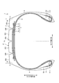
- FIG. 1 is a meridional sectional view of the pneumatic tire according to the present embodiment.
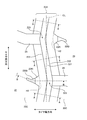
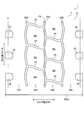
- FIG. 2 is a plan view showing the tread surface of the pneumatic tire according to this embodiment.
- FIG. 3 is a plan view showing a detailed configuration of the inner circumferential main groove.
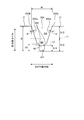
- FIG. 4 is a cross-sectional view taken along the line AA in FIG.
- FIG. 5 is a plan view showing a detailed configuration of the outer circumferential main groove.
- FIG. 6 is a cross-sectional view of the CC section in FIG.
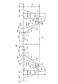
- FIG. 7 is a cross-sectional view taken along the line BB in FIGS. 2, 3 and 5.
- FIG. 8 is an enlarged view showing the blocks in FIG.
- FIG. 9 is an enlarged view showing the outer cutout portion and the outer shallow groove portion in FIG. 8.
- FIG. 10 is an enlarged view showing the inner cutout portion and the inner shallow groove portion in FIG. 8.
- FIG. 11 is a meridional sectional view showing another example of the circumferential main groove.
- FIG. 12 is a plan view showing a schematic configuration of the circumferential main groove.
- FIG. 13 is a plan view showing the tread surface of the pneumatic tire according to this embodiment when it is worn.
- FIG. 1 is a meridional sectional view of a pneumatic tire 1 according to this embodiment.
- FIG. 2 is a plan view showing a tread surface of the pneumatic tire 1 according to this embodiment.
- the tire radial direction means a direction orthogonal to the rotation axis (not shown) of the pneumatic tire 1
- the tire radial direction inner side means a side facing the rotation axis in the tire radial direction, the tire radial direction outer side. Means the side away from the rotation axis in the tire radial direction.
- the tire circumferential direction refers to a circumferential direction with the rotation axis as the central axis.
- the tire width direction means a direction parallel to the rotation axis
- the tire width direction inner side is a side facing the tire equatorial plane (tire equatorial line) CL in the tire width direction
- the tire width direction outer side is the tire width direction.
- the tire equatorial plane CL is a plane that is orthogonal to the rotation axis of the pneumatic tire 1 and passes through the center of the tire width of the pneumatic tire 1.
- the tire width is the width in the tire width direction of the portions located on the outer side in the tire width direction, that is, the distance between the portions farthest from the tire equatorial plane CL in the tire width direction.
- the tire equatorial line is a line on the tire equatorial plane CL and extending in the tire circumferential direction of the pneumatic tire 1. In the present embodiment, the tire equatorial line is designated by the same reference numeral “CL” as the tire equatorial plane.
- a pneumatic tire 1 As shown in FIG. 1, a pneumatic tire 1 according to the present embodiment is provided with a tread portion 2, shoulder portions 3 on both outer sides in the tire width direction, a sidewall portion 4 and a bead portion which are sequentially continuous from each shoulder portion 3. 5 and.
- the pneumatic tire 1 also includes a carcass layer 6 and a belt layer 7.
- the tread portion 2 is made of a rubber material (tread rubber), is exposed at the outermost side in the tire radial direction of the pneumatic tire 1, and the surface thereof becomes the contour of the pneumatic tire 1.
- a tread surface 21 is formed on the outer peripheral surface of the tread portion 2, that is, on the tread surface that comes into contact with the road surface during traveling.
- the tread surface 21 has a plurality of (three in the present embodiment) circumferential main grooves 22A and 22B extending in the tire circumferential direction. Then, the tread surface 21 is divided by the plurality of circumferential main grooves 22A and 22B, extends along the tire circumferential direction, and a plurality (four in the present embodiment) of land portions 20C and 20S are arranged in the tire width direction.
- a plurality of circumferential main grooves 22A and 22B extends along the tire circumferential direction, and a plurality (four in the present embodiment) of land portions 20C and 20S are arranged in the tire width direction.
- the circumferential main groove 22A is an inner circumferential main groove closest to the tire equator line CL.
- the circumferential main groove 22A is arranged on the tire equator line CL.
- the circumferential main groove 22B is the second circumferential main groove closest to the tire equator line CL.
- the circumferential main groove 22B is an outer circumferential main groove provided outside the circumferential main groove 22A which is the inner circumferential main groove in the tire width direction. No other circumferential main groove is provided between the circumferential main groove 22A and the circumferential main groove 22B.
- the main groove is a groove that is required to display a wear indicator defined by JATMA.
- the land portion 20C is partitioned between the circumferential main groove 22A and the circumferential main groove 22B.
- the land portion 20C has a lug groove 24 connected to the circumferential main groove 22A and the circumferential main groove 22B to connect the circumferential main groove 22A and the circumferential main groove 22B.
- the lug grooves 24 extend in a direction intersecting the circumferential main grooves 22A and 22B, and are provided side by side in the tire circumferential direction.
- the land portion 20S is defined on the tire width direction outer side of the circumferential main groove 22B and is arranged on the tire width direction outermost side of the tread portion 2.
- the land portion 20S has a lug groove 30 at the edge portion on the outer side in the tire width direction of the circumferential main groove 22B.
- the lug grooves 30 are provided on the land portion 20S at a predetermined pitch in the tire circumferential direction.
- the end portion of the lug groove 30 on the side close to the tire equatorial plane CL ends in the land portion 20S.
- the end of the lug groove 30 on the side far from the tire equatorial plane CL extends in the tire width direction beyond the tire ground contact end T, and is open to the shoulder portion 3.
- the lug groove is a lateral groove extending in the tire width direction and opens when the tire contacts the ground to function as a groove.
- the tire ground contact end T is a tire and a flat plate when the tire is mounted on a specified rim and a specified internal pressure is applied, and the tire is placed vertically with respect to the plate in a stationary state without applying a load and a load corresponding to the specified load is applied. It is defined as the maximum width position in the tire axial direction on the contact surface with.
- Specified rim means "standard rim” specified by JATMA, "Design Rim” specified by TRA, or “Measuring Rim” specified by ETRTO.
- the specified internal pressure means the “maximum air pressure” specified by JATMA, the maximum value of "TIRE LOAD LIMITS AT VARIOUS COLD INFLATION PRESSURES” specified by TRA, or “INFLATION PRESSURES” specified by ETRTO.
- the specified load means the maximum value of “maximum load capacity” specified by JATMA, “TIRE LOAD LIMITS AT VARIOUS COLD INFLATION PRESSURES” specified by TRA, or “LOAD CAPACITY” specified by ETRTO.
- the shoulder portion 3 is a portion of the tread portion 2 on both outer sides in the tire width direction.
- the sidewall portion 4 is exposed on the outermost side in the tire width direction of the pneumatic tire 1.
- the bead portion 5 has a bead core 51 and a bead filler 52.
- the bead core 51 is formed by winding a bead wire which is a steel wire in a ring shape.
- the bead filler 52 is a rubber material disposed in a space formed by folding the end portion of the carcass layer 6 in the tire width direction outward at the position of the bead core 51.
- the carcass layer 6 is configured such that each tire width direction end portion is folded back from the tire width direction inner side to the tire width direction outer side by the pair of bead cores 51 and is laid around in a toroidal shape in the tire circumferential direction to form a tire skeleton. Is.
- the carcass layer 6 is formed by coating a plurality of carcass cords (not shown) arranged side by side with a coat rubber at an angle with respect to the tire circumferential direction along the tire meridian direction while having an angle in the tire circumferential direction.
- the carcass cord is made of steel or organic fiber (polyester, rayon, nylon, etc.).
- the belt layer 7 has, for example, a multilayer structure in which four layers of belts 71, 72, 73, and 74 are laminated, and is arranged on the outer side of the carcass layer 6 in the tire radial direction in the tread portion 2, and the carcass layer 6 is disposed in the tire. It covers in the circumferential direction.
- Each of the belts 71, 72, 73, and 74 is formed by coating a plurality of cords (not shown) arranged side by side at a predetermined angle with respect to the tire circumferential direction with a coat rubber.
- the cord is made of steel or organic fiber (polyester, rayon, nylon, etc.).
- the groove depth is measured as the maximum value of the distance from the tread surface to the groove bottom in an unloaded state in which the tire is mounted on the specified rim and filled with the specified internal pressure. Further, in a configuration in which the groove has a partial uneven portion or a sipe at the groove bottom, the groove depth is measured excluding these.
- the block BK is defined by the circumferential main grooves 22A and 22B and the lug groove 24 extending in the tire width direction.
- the tread portion 2 may have a sipe (not shown) extending in the tire width direction instead of the lug groove 24.
- the block BK is partitioned by the circumferential main groove 22A, the circumferential main groove 22B, and the sipes thereof.
- the tread portion 2 of the present example is a block defined by two circumferential main grooves extending in the tire circumferential direction and width direction grooves (lug grooves 24 or sipes) extending in the tire width direction.
- the sipe provided in the tread portion 2 is a notch formed in the tread surface, and is distinguished from the lug groove in that it is closed when the tire touches the ground.
- the blocks BK are arranged in the tire circumferential direction on both sides of the tire equatorial line CL in the tire width direction. Therefore, the tread portion 2 of this example constitutes a land portion in which the blocks BK are arranged in the tire circumferential direction.
- the block BK has a notch (also referred to as an inner notch) 23Ki on the edge near the tire equator line CL.
- a shallow groove portion (also referred to as an inner shallow groove portion) 23Gi is connected to the cutout portion 23Ki.
- the block BK has a cutout portion (also referred to as an outer cutout portion) 23Ko at an edge on the side far from the tire equator line CL.
- a shallow groove portion (also referred to as an outer shallow groove portion) 23Go is connected to the cutout portion 23Ko.
- rib-shaped land portions which are partitioned by the circumferential main groove 22A and the circumferential main groove 22B and are continuously provided in the tire circumferential direction are provided in the tread portion 2.
- the notch 23Ki, the shallow groove 23Gi, the notch 23Ko, and the shallow groove 23Go may be provided at the edge of the land.
- FIG. 3 is a plan view showing a detailed configuration of the circumferential main groove 22A which is an inner circumferential main groove.
- FIG. 3 is an enlarged view of the area 26 in FIG.
- the circumferential main groove 22A extends in the tire circumferential direction along the tire equator line CL. Both sides of the circumferential main groove 22A are land portions 20C.
- the circumferential main groove 22A has a zigzag shape in which the tire equatorial line CL is the center line and the main groove 22A is bent and swung to one side and the other side of the tire equatorial line CL.
- the circumferential main groove 22A has a zigzag bent portion 223 connected to the lug groove 24.
- the land portion 20C facing the connection portion between the circumferential main groove 22A and the lug groove 24 has a cutout portion 23Ki connected to the circumferential main groove 22A and a shallow groove portion 23Gi connected to the cutout portion 23Ki and terminating within the land portion 20C.
- the broken line H2 shown in FIG. 3 is an imaginary line of the circumferential main groove 22A when the circumferential main groove 22A is viewed in a plan view.
- FIG. 4 is a diagram showing the structure of the circumferential main groove 22A.
- FIG. 4 is a cross-sectional view taken along the line AA in FIG.
- the circumferential main groove 22A has a step portion 222 on the groove wall 22Aa between the tread surface 21 and the groove bottom 221.
- the step portion 222 extends in the tire circumferential direction.
- the step portion 222 is provided on at least one groove wall 22Aa.
- the step portion 222 forms an inflection portion in which the groove wall angle ⁇ of the groove wall 22Aa changes from the groove opening edge 22Ab of the circumferential main groove 22A toward the groove bottom.
- the circumferential main groove 22A has a groove wall angle ⁇ with respect to the normal line of the tread surface 21 of 10° or more in the groove wall 22Aa from the tread surface 21 which is the groove opening edge 22Ab toward the groove bottom 221 to the step portion 222. It satisfies the range of 45° or less.
- the groove wall angle ⁇ is, for example, 18°.
- FIG. 5 is a plan view showing a detailed configuration of the circumferential main groove 22B which is the outer circumferential main groove.
- FIG. 5 is an enlarged view of the area 27 in FIG.
- the circumferential main groove 22B extends in the tire circumferential direction.
- the side closer to the tire equator line CL is the land portion 20C
- the side farther from the tire equator line CL is the land portion 20S.
- the circumferential main groove 22B has a zigzag shape that bends on the side closer to the tire equator line CL and on the side farther from the tire equator line CL.
- a zigzag-shaped bent portion 223 inward in the tire width direction which is close to the tire equator line CL, is connected to the lug groove 24 and extends outward in the tire width direction far from the tire equator line CL.
- the zigzag-shaped bent portion 223 is connected to the cutout portion 23Ko.
- the land portion 20C has a cutout portion 23Ko connected to the circumferential main groove 22B and a shallow groove portion 23Go connected to the cutout portion 23Ko and terminating within the land portion 20C.
- the broken line H3 shown in FIG. 5 is an imaginary line of the circumferential main groove 22B when the circumferential main groove 22B is seen in a plan view.
- the land portion 20S facing the connecting portion between the circumferential main groove 22B and the lug groove 24 has a cutout portion 25.
- the cutout portion 25 ends at the land portion 20S.
- FIG. 6 is a diagram showing the structure of the circumferential main groove 22B.
- FIG. 6 is a cross-sectional view of the CC section in FIG.
- the circumferential main groove 22B has a step portion 222 on the groove wall 22Ba between the tread surface 21 and the groove bottom 221.
- the step portion 222 extends in the tire circumferential direction.
- the step portion 222 is provided on at least one groove wall 22Ba.
- the step portion 222 forms an inflection portion in which the groove wall angle ⁇ of the groove wall 22Ba changes from the groove opening edge 22Bb of the circumferential main groove 22B toward the groove bottom.
- the groove wall angle ⁇ with respect to the normal line of the tread surface 21 is 10° or more in the groove wall 22Ba from the tread surface 21 which is the groove opening edge 22Bb toward the groove bottom 221 to the step portion 222. It satisfies the range of 45° or less. In this example, the groove wall angle ⁇ is, for example, 15°.
- FIG. 7 is a cross-sectional view taken along the line BB in FIGS. 2, 3 and 5.
- the notch 23Ki is an edge portion on both sides in the tire width direction of the circumferential main groove 22A and is provided in the land portion 20C.
- the notch 23Ki extends in the tire width direction and is connected to the circumferential main groove 22A.
- the cutout portion 23Ki terminates in the land portion 20C that is the first land portion.
- the shallow groove portion 23Gi is connected to the cutout portion 23Ki and terminates in the land portion 20C which is the first land portion.
- the shallow groove portion 23Gi is, for example, a groove having a groove depth of 1 mm and a groove width of 0.5 mm or more and 3.5 mm or less.
- the height of the notch 23Ki in the tire radial direction continuously decreases toward the groove bottom 221 of the circumferential main groove 22A to which it is connected. More specifically, the height of the notch 23Ki does not change stepwise from the end KT1 to which the shallow groove 23Gi connects to the end KT2 on the tire radial inner side, but changes continuously.
- a flat bottom portion 23b is formed at a position near the end portion KT2.
- the cutout portion 23Ki coincides with the groove wall 22Aa of the circumferential main groove 22A in the plane portion of the bottom portion 23b, and also coincides with the step portion 222 of the circumferential main groove 22A.
- the position of the end portion KT1 of the cutout portion 23Ki on the outer side in the tire radial direction matches the position of the end portion GT1 of the groove bottom of the shallow groove portion 23Gi on the cutout portion 23Ki side.
- the position of the end portion GT1 of the shallow groove portion 23Gi on the side of the cutout portion 23Ki is a position corresponding to a tire wear rate of 5% in the tire radial direction.
- the position of the end portion KT2 on the tire radial direction inner side of the cutout portion 23Ki coincides with the position of the end portion of the circumferential main groove 22A on the side closer to the groove bottom 221 of the step portion 222.
- the position of the end of the step portion 222 of the circumferential main groove 22A on the side closer to the groove bottom 221 is the position corresponding to 70% of wear of the tire in the tire radial direction. Therefore, the height of the notch 23Ki does not change until the wear of the tire reaches 5%, but the wear of the tire changes from 5% onward and continuously decreases until the wear of the tire reaches 70%. .. That is, the height of the notch 23Ki continuously decreases from the height corresponding to the tire wear of 5% to the height corresponding to the tire wear of 70%.
- the ratio DK/D of the maximum height DK of the cutout portion 23Ki to the groove depth D of the circumferential main groove 22A connected to the cutout portion 23Ki is preferably 0.60 or more and 0.85 or less.
- the ratio DK/D is a value within this range, the uneven wear resistance performance and the drainage performance are improved.
- the ratio DK/D is 0.71.
- the inclination angle ⁇ C formed by the inclined portion 23a of the cutout portion 23Ki with respect to the normal line of the tread surface 21 is preferably larger than 20° and not larger than 45°. Within this angle range, the uneven wear resistance performance is improved.
- the tilt angle ⁇ C is more preferably 20° or more and 40° or less.
- the ratio DG/DK of the depth DG of the shallow groove portion 23Gi to the height DK of the notch 23Ki to which the shallow groove portion 23Gi is connected is preferably larger than 0 and 0.2 or less.
- the ratio DG/DK is more preferably 0.02 or more and 0.18 or less.
- the ratio LK/LG of the length LK in the tire width direction of the flat portion of the bottom portion 23b of the cutout 23Ki to the length LG in the tire width direction of the shallow groove portion 23Gi is preferably more than 0 and 0.5 or less. If the ratio LK/LG is a value within this range, the uneven wear resistance performance is improved.
- the ratio LK/LG is more preferably 0.05 or more and 0.50 or less, and further preferably 0.1 or more and 0.3 or less.
- the cutout portion 23Ko is an edge portion on the tire width direction inner side of the circumferential main groove 22B and is provided in the land portion 20C.
- the notch 23Ko extends in the tire width direction and is connected to the circumferential main groove 22B.
- the cutout portion 23Ko ends in the land portion 20C that is the first land portion.
- the shallow groove portion 23Go is connected to the notch portion 23Ko and terminates in the land portion 20C which is the first land portion.
- the shallow groove portion 23Go is, for example, a groove having a groove depth of 1 mm and a groove width of 0.5 mm or more and 3.5 mm or less.
- the height of the notch 23Ko in the tire radial direction continuously decreases toward the groove bottom 221 of the circumferential main groove 22B to which the notch 23Ko is connected. More specifically, the notch 23Ko has an inclination in which the height of the notch 23Ko does not change stepwise from the end KT1 to which the shallow groove 23Go is connected to the end KT2 on the inner side in the tire radial direction, but continuously. It has a part 23a.
- a flat bottom portion 23b is formed at a position near the end portion KT2.
- the cutout portion 23Ko coincides with the groove wall 22Ba of the circumferential main groove 22B in the plane portion of the bottom portion 23b, and also coincides with the step portion 222 of the circumferential main groove 22B.
- the position of the end portion KT1 of the cutout portion 23Ko on the outer side in the tire radial direction matches the position of the end portion GT1 of the groove bottom of the shallow groove portion 23Go on the cutout portion 23Ko side.
- the position of the end portion GT1 of the shallow groove portion 23Go on the side of the cutout portion 23Ko is a position corresponding to a tire wear rate of 5% in the tire radial direction.
- the position of the end portion KT2 on the tire radial inner side of the cutout portion 23Ko coincides with the position of the end portion of the circumferential main groove 22B on the side closer to the groove bottom 221 of the step portion 222.
- the position of the end of the circumferential main groove 22B on the side closer to the groove bottom 221 of the step 222 is a position corresponding to 70% wear of the tire in the tire radial direction. Therefore, the height of the notch 23Ko does not change until the wear of the tire reaches 5%, but the wear of the tire changes from 5% onward and continuously decreases until the wear of the tire reaches 70%. .. That is, the height of the cutout portion 23Ko continuously decreases from the height corresponding to the tire wear of 5% to the height corresponding to the tire wear of 70%.
- the ratio DK/D of the maximum height DK of the notch 23Ko to the groove depth D of the circumferential main groove 22B to which the notch 23Ko is connected is preferably 0.60 or more and 0.85 or less.
- the ratio DK/D is a value within this range, the uneven wear resistance performance and the drainage performance are improved.
- the ratio DK/D is 0.71.
- the inclination angle ⁇ S formed by the inclined portion 23a of the cutout 23Ko with respect to the normal line of the tread surface 21 is preferably larger than 20° and not larger than 45°. Within this tilt angle range, the uneven wear resistance performance is improved.
- the inclination angle ⁇ S is more preferably 20° or more and 40° or less.
- the inclination angle ⁇ S formed by the cutout portion 23Ko is larger than the inclination angle ⁇ C formed by the cutout portion 23Ki.
- the ratio DG/DK of the depth DG of the shallow groove portion 23Go to the height DK of the cutout portion 23Ko to which the shallow groove portion 23Go is connected is preferably larger than 0 and 0.2 or less.
- the ratio DG/DK is more preferably 0.02 or more and 0.18 or less.
- the ratio LK/LG of the length LK in the tire width direction of the flat portion of the bottom portion 23b of the cutout 23Ko to the length LG in the tire width direction of the shallow groove portion 23Go is preferably more than 0 and 0.5 or less. If the ratio LK/LG is a value within this range, the uneven wear resistance performance is improved.
- the ratio LK/LG is more preferably 0.05 or more and 0.50 or less, and further preferably 0.1 or more and 0.3 or less.
- FIG. 8 is an enlarged view of the block BK in FIG.
- the distance in the tire width direction between the end of the inner cutout 23Ki on the inner circumferential main groove 22A side and the end of the outer cutout 23Ko on the outer circumferential main groove 22B side is defined as the distance WD.
- the distance WD corresponds to the width of the land portion 20C that is the first land portion in the tire width direction.
- the distance in the tire width direction from the end of the inner notch 23Ki on the inner circumferential main groove 22A side to the end of the inner shallow groove 23Gi connected to the inner notch 23Ki is defined as the distance d11.
- the distance d11 is the length of the inner cutout 23Ki and the inner shallow groove 23Gi in the tire width direction.
- the ratio d11/WD of the distance d11 to the distance WD is preferably 0.1 or more and 0.3 or less. When the ratio d11/WD is 0.1 or more and 0.3 or less, the uneven wear resistance performance is improved.
- the ratio d11/WD is more preferably 0.2.
- a distance in the tire width direction from the end of the outer cutout 23Ko on the outer circumferential main groove 22B side to the end of the outer shallow groove 23Go connected to the outer cutout 23Ko with respect to the distance WD is defined as a distance d12. ..
- the distance d12 is the length of the outer cutout portion 23Ko and the outer shallow groove portion 23Go in the tire width direction.
- the ratio d12/D of the distance d12 to the distance WD is preferably 0.1 or more and 0.4 or less. When the ratio d12/WD is 0.1 or more and 0.4 or less, the uneven wear resistance performance is improved.
- the ratio d12/WD is more preferably 0.3.
- FIG. 9 is an enlarged view showing the outer cutout portion 23Ko and the outer shallow groove portion 23Go in FIG.
- a broken line H3 is an imaginary line of the circumferential main groove 22B when the circumferential main groove 22B is seen in a plan view.
- the projected area of the outer cutout 23Ko is S2.
- the projected area of the outer shallow groove portion 23Go connected to the outer cutout portion 23Ko is S1.
- the projected area is the area of the tread surface 21 when projected from the outside in the tire radial direction toward the inside in the tire radial direction.
- the ratio S1/S2 of the projected area S1 to the projected area S2 is preferably 0.1 ⁇ S1/S2 ⁇ 0.5. More preferably, 0.15 ⁇ S1/S2 ⁇ 0.3.
- the ratio S1/S2 is lower than 0.1, the drainage property is lowered, which is not preferable. If the ratio S1/S2 is higher than 0.5, the ground contact area is reduced and the uneven wear property is reduced, which is not preferable.
- the ratio S2/S of the projected area S2 of the outer cutout 23Ko shown in FIG. 9 to the ground contact area S of the block BK shown in FIG. 8 is 0 ⁇ S2/S ⁇ 0.1. More preferably, 0.005 ⁇ S2/S ⁇ 0.100.
- the ratio S2/S is higher than 0.100, the ground contact area of the block BK is reduced and the uneven wear resistance is deteriorated, which is not preferable.
- the ground contact area S is the tire width direction in which the tread surface 21 of the block BK is in contact with the road surface when the pneumatic tire 1 is assembled on a regular rim and the regular internal pressure is filled and 70% of the regular load is applied. And the area of the region in the tire circumferential direction.
- FIG. 10 is an enlarged view showing the inner cutout portion 23Ki and the inner shallow groove portion 23Gi in FIG.
- a broken line H2 is an imaginary line of the circumferential main groove 22A when the circumferential main groove 22A is seen in a plan view.
- the projected area of the inner cutout 23Ki is S4.
- the projected area of the inner shallow groove portion 23Gi connected to the inner cutout portion 23Ki is S3.
- the ratio S3/S4 of the projected area S3 to the projected area S4 is preferably 0.5 ⁇ S3/S4 ⁇ 0.9. More preferably, 0.65 ⁇ S3/S4 ⁇ 0.80.
- the ratio S3/S4 is lower than 0.5, the drainage property is deteriorated, which is not preferable.
- the ratio S3/S4 is higher than 0.9, the ground contact area is reduced and the uneven wear resistance is deteriorated, which is not preferable.
- the ratio S4/S of the projected area S4 of the inner cutout 23Ki shown in FIG. 10 to the ground contact area S of the block BK shown in FIG. 8 is 0 ⁇ S4/S ⁇ 0.1. More preferably, 0.005 ⁇ S4/S ⁇ 0.100.
- the projected area of the inner cutout portion 23Ki is higher than 0.100 with respect to the ground contact area S of the block BK, the ground contact area of the block BK is reduced and the uneven wear resistance performance is deteriorated, which is not preferable.
- a plurality of inner cutout portions 23Ki and inner shallow groove portions 23Gi are arranged in the tire circumferential direction. Further, a plurality of outer cutout portions 23Ko and outer shallow groove portions 23Go are arranged in the tire circumferential direction.
- the ratio of the displacement amount PK of the arrangement of the inner cutouts 23Ki to the pitch length PB1 of the arrangement of the outer cutouts 23Ko is preferably 0.1 or more and 0.5 or less. Further, it is preferable that the ratio of the displacement amount PG of the arrangement of the inner shallow groove portions 23Gi to the pitch length PB2 of the arrangement of the outer shallow groove portions 23Go is 0.1 or more and 0.5 or less.
- the uneven wear resistance is improved by optimizing the arrangement of the inner cutout portion 23Ki and the outer notch portion 23Ko and by optimizing the arrangement of the inner shallow groove portion 23Gi and the outer shallow groove portion 23Go.
- the tread portion 2 when focusing on the land portion 20C that is the first land portion (20-1), the tread portion 2 includes the second land portion (outer side of the outer circumferential main groove 22B, which is provided on the outer side in the tire width direction). 20-2) which is a land portion 20S and a second land portion (20-2) which is a land portion 20S and has a notch portion 25 which is a second notch portion which terminates in the land portion 20S.
- the edge component increases and the drainage property improves.
- the tread portion 2 is the land which is the third land portion (20-3) provided with the inner circumferential main groove 22A interposed therebetween.
- the portion 20C a notch portion 23Ki that is a third notch portion that is provided in the land portion 20C and that extends in the tire width direction and is connected to the inner circumferential main groove 22A, and the third land portion that is connected to the notch portion 23Ki.
- a shallow groove portion 23Gi that terminates in the land portion 20C that is the portion (20-3).
- FIG. 11 is a meridional sectional view showing another example of the circumferential main groove.
- the circumferential main grooves 22A and 22B have a virtual dividing line L1 parallel to the straight line connecting the groove opening edges 22Ab and 22Bb in the meridional section.
- a tire radial outer sectional area SU and a tire radial inner sectional area SD satisfies the relationship of 0.15 ⁇ SD/SU ⁇ 0.60.
- the relationship between the ratio SD/SU of the sectional area SD on the tire radial inner side to the sectional area SU on the tire radial outer side is such that the groove walls 22Aa, 22Ba approach the groove bottom 221. It can be obtained by inclining as described above or having a step portion 222 so that the groove width becomes narrow in the middle of the groove walls 22Aa and 22Ba.
- the relationship of the ratio SD/SU is not clearly shown in the figure except that the circumferential main grooves 22A, 22B have the zigzag shape as described above, but the circumferential main grooves 22A, 22B are arranged along the tire circumferential direction. This includes extending straightly and meandering in an S shape.
- the circumferential main groove 22A is shown as a representative. Although not clearly shown in the drawing, the same applies to the circumferential main groove 22B.
- the circumferential main groove 22A shown in FIG. 11A is inclined with respect to the normal line of the tread surface 21 so that one groove wall 22Aa approaches the other groove wall 22Aa toward the groove bottom 221, and the groove wall 22Aa is inclined.
- 22Aa has an inflection portion 224 in which the groove wall angle changes so as to be small and sharp on the way.
- the step portion 222 also is included in the meaning of the inflection portion 224 because the groove wall angle of the groove wall 22Aa changes.
- the circumferential main groove 22A shown in FIG. 11B is similar to the embodiment shown in FIGS. 4 and 6, and both groove walls 22Aa are inclined toward the groove bottom 221 with respect to the normal line of the tread surface 21. In parallel with each other, a step 222 is formed in the middle of the groove wall 22Aa.
- the circumferential main groove 22A shown in FIG. 11(c) is inclined with respect to the normal line of the tread surface 21 so that both groove walls 22Aa come closer to each other toward the groove bottom 221, and the groove wall angle of both groove walls 22Aa.
- the circumferential main groove 22A shown in FIG. 11(d) is inclined with respect to the normal line of the tread surface 21 so that both groove walls 22Aa approach each other toward the groove bottom 221.
- the circumferential main groove 22A shown in FIG. 11(d) is formed so as to be curved so that both groove walls 22Aa bulge in directions toward each other.
- both groove walls 22Aa are parallel to the groove bottom 221 without being inclined with respect to the normal line of the tread surface 21, and a step portion 222 is formed in the middle of the groove wall 22Aa. Has been formed. Further, both groove walls 22Aa are inclined with respect to the normal line of the tread surface 21 so as to approach each other on the way from the step portion 222 to the groove bottom 221.
- both groove walls 22Aa are parallel to the groove bottom 221 without being inclined with respect to the normal line of the tread surface 21, and a step portion 222 is formed in the middle of the groove wall 22Aa.
- a plurality here, two are formed.
- both groove walls 22Aa are parallel to the groove bottom 221 without being inclined with respect to the normal line of the tread surface 21, and the projection 225 is formed on the groove bottom 221. There is.
- the ratio SD/SU preferably satisfies the relationship of 0.20 ⁇ SD/SU ⁇ 0.50.
- the groove width W1 at the 1/4 position and the groove width W of the groove opening satisfy the relationship of W1/W ⁇ 0.78.
- the inflection portion 224 (the stepped portion 224 in which the groove wall angle changes from the groove opening edges 22Ab and 22Bb toward the groove bottom 221). 222). This makes it possible to satisfy the relationships of SD/SU and W1/W described above.
- the height HT in the tire radial direction from the groove bottom 221 to the inflection portion 224 (step portion 222) and the groove depth D are It is preferable to satisfy the relationship of 0.1 ⁇ HT/D ⁇ 0.5.
- the inflection portion 224 (step portion 222) closest to the groove bottom 221 is used as a reference.
- the ratio HT/D of the height HT in the tire radial direction from the groove bottom 221 to the inflection portion 224 (step portion 222) to the groove depth D it secures a rubber volume that squeezes out, and prevents the groove bottom 221 from being hit by chewing stones to prevent stones from being chewed.
- the ratio HT/D preferably satisfies the relationship of 0.2 ⁇ HT/D ⁇ 0.4.
- the groove wall angles ⁇ and ⁇ By setting the groove wall angles ⁇ and ⁇ to 10° or more, it is possible to improve the dischargeability of stones that have entered. On the other hand, by setting the groove wall angles ⁇ and ⁇ to 45° or less, it is possible to suppress an increase in the groove width of the circumferential main grooves 22A and 22B, and to design freely by limiting the number of circumferential main grooves 22A and 22B in the tread pattern. It is possible to suppress a decrease in degree.
- the groove wall angles ⁇ and ⁇ preferably satisfy the range of 15° or more and 35° or less.
- FIG. 12 is a plan view showing a schematic configuration of the circumferential main groove.
- the circumferential main grooves 22A, 22B have a zigzag shape in which a plurality of bent portions 223 swinging in the tire width direction are alternately arranged in the tire circumferential direction.
- the edge component is increased and the wet braking performance, which is the traction performance, is improved.
- the circumferential main grooves 22A, 22B have a zigzag pitch pitch P1 of one cycle and a tire circumferential length TL in the tire circumferential direction of 0.005 ⁇ P1/TL ⁇ 0.03. It is preferable to satisfy the relationship.
- the tire circumferential length TL is the total length of the circumferential main grooves 22A and 22B in the opening portion to the tread surface 21 in the tire circumferential direction in a stationary state in which the tire is mounted on the prescribed rim and a prescribed internal pressure is applied and a load is not applied. ..
- the edge component due to the zigzag shape can be effectively obtained.
- the ratio P1/TL is 0.0185, for example.
- the zigzag-shaped amplitude A of one cycle and the tire development width TDW may satisfy the relationship of 0.01 ⁇ A/TDW ⁇ 0.05. preferable.
- the amplitude A of one cycle of the zigzag shape is the maximum swing width in the tire width direction in the zigzag shape.
- the tire development width TDW is a width obtained by developing the maximum width of the tread pattern on a plane, and in the present example, the tire development width TDW is provided between the tire width direction outer ends of the outermost lug grooves 30 in the tire width direction. Equivalent to.
- the ratio A/TDW of the amplitude A of one cycle of the zigzag shape to the tire development width TDW is 0.01 or more.
- the ratio A/TDW is 0.05 or less, the stress concentration due to the excessive wobbling width of the zigzag shape is suppressed and the edge portions of the circumferential main grooves 22A and 22B caused by the bent portion 223 are chipped or broken. Can be prevented.
- A/TDW is 0.027, for example.
- a plurality of circumferential main grooves 22A and 22B are provided side by side in the tire width direction.
- a zigzag-shaped bent portion is formed in each of the circumferential main grooves 22A and 22B adjacent in the tire width direction. It is preferable that the position of 223 is different in the tire circumferential direction. Since the position of the zigzag bent portion 223 differs in the tire circumferential direction, the edge component due to the zigzag shape can be effectively obtained, and the rigidity of the land portion 20C partitioned between the circumferential main grooves 22A and 22B can be improved. It is possible to maintain and improve uneven wear resistance.
- a plurality of circumferential main grooves 22A and 22B are provided side by side in the tire width direction, and a zigzag-shaped tire is provided with respect to two circumferential main grooves 22A and 22B that are adjacent in the tire width direction.
- a plurality of lug grooves 24 are provided by connecting the bent portions 223 that are closest to each other in the width direction and aligned in the tire circumferential direction, and are adjacent to each other in the tire circumferential direction with two circumferential main grooves 22A and 22B that are adjacent in the tire width direction. It is preferable that the block BK is defined by the lug groove 24 of the book.
- the lug groove 24 is provided by connecting the bent portions 223 of the two circumferential main grooves 22A and 22B that are closest to each other in the tire width direction of the zigzag shape, the other two circumferential main grooves 22A and 22B are It is possible to shorten the extending length of the lug groove 24 as compared with connecting the portions of. Therefore, it is possible to suppress the number of occurrences of stone trapping in the lug groove 24.
- the block BK has one wide portion BKa having the largest width in the tire width direction at the center in the tire circumferential direction due to the zigzag shape of the circumferential main grooves 22A and 22B, and both ends in the tire circumferential direction. It is preferable that each has a narrow portion BKb having the smallest width in the tire width direction. According to this configuration, the edge component can be effectively obtained, the block BK is formed in a substantially hexagonal shape in plan view, and the block rigidity is improved as compared with the configuration in which the center in the tire circumferential direction is narrow. It is possible to secure and improve uneven wear resistance.
- the lug groove 24 preferably has bent portions 24a at at least two positions.
- the edge component is increased and the wet braking performance which is the traction performance is improved.
- the bent portion 24a is provided at two locations in one lug groove 24.
- the lug groove 24 has a ratio Lb/La of the distance Lb from the end of the lug groove 24 to the bent portion 24a to the extension length La of the lug groove 24 in the tire width direction. Preferably satisfies the range of 0.10 ⁇ Lb/La ⁇ 0.20.
- the edge effect is reduced, and if the bent portion 24a is too far from the end portion of the lug groove 24, the center portion of the lug groove 24 becomes extremely bent, ensuring block rigidity. If it is not possible, the uneven wear resistance may be deteriorated, or it may cause chipping or burning. Within the range of the ratio Lb/La, the edge effect can be effectively obtained, and the uneven wear resistance and the durability can be secured.
- the groove depth DL of the lug groove 24 and the groove depth D of the circumferential main grooves 22A and 22B to which the lug groove 24 is connected are DL/D ⁇ 0.8. It is preferable to satisfy the relationship.
- the lug groove 24 shallower than the circumferential main grooves 22A and 22B, it is possible to prevent the stress applied to the land portion 20C from being concentrated in a part, and to reduce the stress generated in the circumferential main grooves 22A and 22B.
- the groove crack resistance performance in the groove 24 can be improved.
- the inclined portion 23a has an inclination angle ⁇ C toward the groove bottom 221 of the circumferential main groove 22A near the tire equatorial plane CL and a circumferential main direction near the tire ground contact end T. It is preferable that the inclination angle ⁇ S of the groove 22B toward the groove bottom 221 satisfies the relations of ⁇ C ⁇ 20° and ⁇ C ⁇ S.
- the inclination angle ⁇ S is relatively larger than the inclination angle ⁇ C near the tire ground contact end T because of concern about deterioration in groove crack resistance.
- the cutouts 23Ki and 23Ko are arranged such that the openings 23c connected to the circumferential main grooves 22A and 22B are displaced from each other in the tire circumferential direction. It is preferable that one edges of the portion 23c are aligned on a reference line L3 parallel to the tire width direction.
- the reference line L3 passes through the center point of the block BK in the tire circumferential direction. Therefore, each opening 23c is arranged at a target position with respect to the center point of the block BK in the tire circumferential direction.
- the notch 23Ki is preferably provided facing one end of the lug groove 24 with the circumferential main groove 22A interposed therebetween.
- a pocket-shaped space is created between the block BK and the opposing block BK with the circumferential main groove 22A interposed therebetween, and stones may be caught in the groove bottom 221 of the circumferential main groove 22A.
- the notch 23Ki on the extension line of the lug groove 24, it is possible to accelerate the discharge of stones and prevent stone trapping.
- the maximum height DK in the tire radial direction of the cutouts 23Ki, 23Ko and the groove depths of the circumferential main grooves 22A, 22B to which the cutouts 23Ki, 23Ko are connected It is preferable that D satisfies the relationship of 0.60 ⁇ DK/D ⁇ 0.85.
- the drainage performance can be improved by setting the ratio DK/D of the maximum height DK in the tire radial direction of the notches 23Ki, 23Ko to the groove depth D of the circumferential main grooves 22A, 22B to 0.60 or more, thereby improving the traction performance. Can be improved.
- the block rigidity of the block BK is maintained by setting the ratio DK/D of the maximum height DK in the tire radial direction of the notches 23Ki and 23Ko to the groove depth D of the circumferential main grooves 22A and 22B to 0.85 or less.
- the uneven wear resistance performance can be improved.
- FIG. 13 is a plan view showing a tread surface of the pneumatic tire 1 according to the present embodiment when worn.
- FIG. 13 shows a case where the circumferential main grooves 22A and 22B have worn down to the step 222 (for example, tire wear 70%).
- the step 222 for example, tire wear 70%
- the lug groove 30 ends in the land portion 20S and is not connected to the circumferential main groove 22B provided on the outermost side in the tire width direction. That is, a continuous groove extending from the circumferential main groove 22B to the tire ground contact end T is not arranged outside the circumferential main groove 22B provided on the outermost side in the tire width direction. Therefore, the rigidity of the outermost land portion 20S in the tire width direction can be maintained and the uneven wear resistance can be improved.
- a pneumatic tire having a tire size of 11R22.5 (pneumatic tire for heavy load) was mounted on a specified rim, filled with specified air pressure, and mounted on a drive shaft of a test vehicle (2-D/tractor head). ..
- the number of stones remaining in the groove is measured after running on a paved road for 2 hours on an unpaved road in the test vehicle for 10 hours. Then, the number of stones remaining in the groove is indexed, and the pneumatic tire of the conventional example is evaluated as a reference value (100). This evaluation shows that the larger the index value, the smaller the number of stones remaining in the groove, and the better the anti-stone bite performance.
- Wet braking performance is evaluated according to R117-02 (ECE Regulation No. 117 Revision 2), and the wet braking performance is measured on the test vehicle. Then, the braking distance is indexed, and the pneumatic tire of the conventional example is used as a reference value (100) for evaluation. This evaluation shows that the larger the index value, the shorter the braking distance and the better the wet braking performance.
- the pneumatic tires of Conventional Example and Comparative Example 1 in Table 1 have SD/SU outside the specified range in the circumferential main groove.
- SD/SU is within the specified range in the circumferential main groove.
- “Block shape: presence or absence of wide portion and narrow portion” “Yes” has one wide portion at the center of the tire circumferential direction in one block and has narrow portions at both ends in the tire circumferential direction. (See FIG. 2) means that the “two wide parts” have two wide parts in the tire circumferential direction in one block and have narrow parts at the center and both ends in the tire circumferential direction. means.
Landscapes
- Engineering & Computer Science (AREA)
- Mechanical Engineering (AREA)
- Tires In General (AREA)
Abstract
複雑な形状を取らず石噛みを防止する。 トレッド部のトレッド面21にタイヤ周方向に延びる周方向主溝22Aを有しており、周方向主溝22Aは、子午断面において、各溝開口縁22Abを結ぶ直線と平行な仮想区分線L1を溝深さの1/2位置(D/2)に引いてタイヤ径方向外側とタイヤ径方向内側とに区分した場合に、タイヤ径方向外側の断面積SUと、タイヤ径方向内側の断面積SDとが、0.15≦SD/SU≦0.60の関係を満たす。
Description
本発明は、空気入りタイヤに関する。
非舗装路と舗装路とを走行することが想定される重荷重用空気入りタイヤなどでは、非舗装路の走行時に溝への石噛みによりストンドリリングが発生し、内部構造であるベルトを損傷することで、トレッドセパレーションが生じたり、更生率が低下したりするおそれがあった。
従来、例えば、特許文献1には、摩耗時における制動性能および操縦安定性を改善することを目的とし、トレッドパターンのタイヤ周方向に延びる縦溝について、少なくとも片側の側壁から中央部に向かって張り出して下部の溝幅を狭めるように棚段を設けることが開示されている。
石噛み防止の構造としては、溝底や溝壁に部分的に突起を設けることが一般的に知られている。しかし、部分的に突起を設けると複雑な形状になり、例えば、加硫故障などの不良の原因となり成型し難い。そこで、複雑な形状を取らず石噛みを防止することのできる空気入りタイヤが望まれている。
本発明は、上記に鑑みてなされたものであって、複雑な形状を取らず石噛みを防止することのできる空気入りタイヤを提供することを目的とする。
上述した課題を解決し、目的を達成するために、本発明の一態様に係る空気入りタイヤは、トレッド部のトレッド面にタイヤ周方向に延びる周方向主溝を有しており、前記周方向主溝は、子午断面において、各溝開口縁を結ぶ直線と平行な仮想区分線を溝深さの1/2位置に引いてタイヤ径方向外側とタイヤ径方向内側とに区分した場合に、タイヤ径方向外側の断面積SUと、タイヤ径方向内側の断面積SDとが、0.15≦SD/SU≦0.60の関係を満たす。
また、本発明の一態様に係る空気入りタイヤでは、前記周方向主溝は、子午断面において、前記仮想区分線を溝深さの1/4位置に引いた場合に、当該1/4位置での溝幅W1と、溝開口部の溝幅Wとが、W1/W≦0.78の関係を満たすことが好ましい。
また、本発明の一態様に係る空気入りタイヤでは、前記周方向主溝は、少なくとも一方の溝壁に、溝開口縁から溝底に向かって溝壁角度が変化する変曲部を有することが好ましい。
また、本発明の一態様に係る空気入りタイヤでは、前記周方向主溝は、溝底から前記変曲部までのタイヤ径方向の高さHTと、溝深さDとが、0.1≦HT/D≦0.5の関係を満たすことが好ましい。
また、本発明の一態様に係る空気入りタイヤでは、前記周方向主溝は、溝壁の溝開口縁から溝底に向かう前記トレッド面の法線に対する溝壁角度が10°以上45°以下の範囲を満たすことが好ましい。
また、本発明の一態様に係る空気入りタイヤでは、前記周方向主溝は、タイヤ幅方向に振れるジグザグ形状を有することが好ましい。
また、本発明の一態様に係る空気入りタイヤでは、前記周方向主溝は、前記ジグザグ形状の1周期のピッチ長P1と、タイヤ周方向のタイヤ周長TLとが、0.005≦P1/TL≦0.03の関係を満たすことが好ましい。
また、本発明の一態様に係る空気入りタイヤでは、前記周方向主溝は、前記ジグザグ形状の1周期の振幅Aと、タイヤ展開幅TDWとが、0.01≦A/TDW≦0.05の関係を満たすことが好ましい。
また、本発明の一態様に係る空気入りタイヤでは、前記周方向主溝がタイヤ幅方向に複数並んで設けられており、タイヤ幅方向で隣接する各前記周方向主溝において、前記ジグザグ形状の屈曲部の位置がタイヤ周方向で異なることが好ましい。
また、本発明の一態様に係る空気入りタイヤでは、前記周方向主溝がタイヤ幅方向に複数並んで設けられており、タイヤ幅方向で隣接する2本の前記周方向主溝に対し前記ジグザグ形状のタイヤ幅方向で最も近づく相互の屈曲部を繋ぎタイヤ周方向に複数並んで設けられたラグ溝と、タイヤ幅方向で隣接する2本の前記周方向主溝とタイヤ周方向で隣接する2本の前記ラグ溝とで区画されたブロックと、を有することが好ましい。
また、本発明の一態様に係る空気入りタイヤでは、前記ブロックは、タイヤ周方向の中央に1つの幅広部を有しタイヤ周方向の両端にそれぞれ幅狭部を有することが好ましい。
また、本発明の一態様に係る空気入りタイヤでは、前記ラグ溝は、少なくとも2箇所に屈曲部を有することが好ましい。
また、本発明の一態様に係る空気入りタイヤでは、前記ラグ溝の溝深さDLと、当該ラグ溝が接続する前記周方向主溝の溝深さDとが、DL/D≦0.8の関係を満たすことが好ましい。
また、本発明の一態様に係る空気入りタイヤでは、前記ブロックを区画する一方の前記周方向主溝がタイヤ赤道面寄りに配置され、他方の前記周方向主溝がタイヤ接地端寄りに配置されており、前記ブロックは、タイヤ幅方向両側において前記周方向主溝にそれぞれ接続して前記ブロックの内部で終端する切欠部を有し、それぞれの前記切欠部は、それぞれの前記周方向主溝の溝底に向かって前記トレッド面の法線に対して傾斜する傾斜部を有し、それぞれの前記傾斜部は、一方の前記周方向主溝の溝底に向かう傾斜角度θCと、他方の前記周方向主溝の溝底に向かう傾斜角度θSとが、θC≦20°、かつθC<θSの関係を満たすことが好ましい。
また、本発明の一態様に係る空気入りタイヤでは、前記ブロックは、タイヤ幅方向両側において前記周方向主溝にそれぞれ接続して前記ブロックの内部で終端する切欠部を有し、それぞれの前記切欠部は、それぞれの前記周方向主溝に接続する開口部がタイヤ周方向でずれて配置され、各前記開口部の片方の縁同士がタイヤ周方向で一致する、ことが好ましい。
また、本発明の一態様に係る空気入りタイヤでは、前記ブロックは、タイヤ幅方向両側において前記周方向主溝にそれぞれ接続して前記ブロックの内部で終端する切欠部を有し、前記切欠部は、前記周方向主溝を挟んで前記ラグ溝の一端と向き合って設けられていることが好ましい。
また、本発明の一態様に係る空気入りタイヤでは、前記切欠部のタイヤ径方向の最大高さDKと、当該切欠部が接続する前記周方向主溝の溝深さDとが、0.60≦DK/D≦0.85の関係を満たすことが好ましい。
また、本発明の一態様に係る空気入りタイヤでは、前記周方向主溝は、少なくとも前記ラグ溝が接続する側の溝壁に段部が形成されており、前記ラグ溝の溝深さDLと、前記段部の前記トレッド面からの深さDHとが、DL/DH≦1.1の関係を満たすことが好ましい。
また、本発明の一態様に係る空気入りタイヤでは、タイヤ幅方向最外側に設けられた前記周方向主溝のタイヤ幅方向外側に前記周方向主溝からタイヤ接地端に至り連続する溝を配置しないことが好ましい。
本発明によれば、複雑な形状を取らず石噛みを防止することができる。
以下に、本発明の実施形態を図面に基づいて詳細に説明する。なお、この実施形態によりこの発明が限定されるものではない。また、この実施形態の構成要素には、当業者が置換可能かつ容易なもの、あるいは実質的に同一のものが含まれる。また、この実施形態に記載された複数の変形例は、当業者自明の範囲内にて任意に組み合わせが可能である。また、一部の構成要素を用いない場合もある。
(空気入りタイヤ)
図1は、本実施形態に係る空気入りタイヤ1の子午断面図である。図2は、本実施形態に係る空気入りタイヤ1のトレッド面を示す平面図である。
図1は、本実施形態に係る空気入りタイヤ1の子午断面図である。図2は、本実施形態に係る空気入りタイヤ1のトレッド面を示す平面図である。
以下の説明において、タイヤ径方向とは、空気入りタイヤ1の回転軸(図示せず)と直交する方向をいい、タイヤ径方向内側とはタイヤ径方向において回転軸に向かう側、タイヤ径方向外側とはタイヤ径方向において回転軸から離れる側をいう。また、タイヤ周方向とは、上記回転軸を中心軸とする周り方向をいう。また、タイヤ幅方向とは、上記回転軸と平行な方向をいい、タイヤ幅方向内側とはタイヤ幅方向においてタイヤ赤道面(タイヤ赤道線)CLに向かう側、タイヤ幅方向外側とはタイヤ幅方向においてタイヤ赤道面CLから離れる側をいう。タイヤ赤道面CLとは、空気入りタイヤ1の上記回転軸に直交するとともに、空気入りタイヤ1のタイヤ幅の中心を通る平面である。タイヤ幅は、タイヤ幅方向の外側に位置する部分同士のタイヤ幅方向における幅、つまり、タイヤ幅方向においてタイヤ赤道面CLから最も離れている部分間の距離である。タイヤ赤道線とは、タイヤ赤道面CL上にあって空気入りタイヤ1のタイヤ周方向に沿う線をいう。本実施形態では、タイヤ赤道線にタイヤ赤道面と同じ符号「CL」を付す。
図1に示すように、本実施形態にかかる空気入りタイヤ1は、トレッド部2と、そのタイヤ幅方向両外側のショルダー部3と、各ショルダー部3から順次連続するサイドウォール部4およびビード部5とを有している。また、この空気入りタイヤ1は、カーカス層6と、ベルト層7とを含む。
トレッド部2は、ゴム材(トレッドゴム)からなり、空気入りタイヤ1のタイヤ径方向の最も外側で露出し、その表面が空気入りタイヤ1の輪郭となる。トレッド部2の外周表面、つまり、走行時に路面と接触する踏面には、トレッド面21が形成されている。トレッド面21は、タイヤ周方向に延在する複数(本実施形態では3本)の周方向主溝22A、22Bを有する。そして、トレッド面21は、これら複数の周方向主溝22A、22Bによって区画され、タイヤ周方向に沿って延在し、タイヤ幅方向に複数(本実施形態では4本)並ぶ陸部20C、20Sを有する。
周方向主溝22Aは、タイヤ赤道線CLに最も近い内側周方向主溝である。本実施形態において、周方向主溝22Aは、タイヤ赤道線CLの上に配置されている。周方向主溝22Bは、2番目にタイヤ赤道線CLに近い周方向主溝である。周方向主溝22Bは、内側周方向主溝である周方向主溝22Aのタイヤ幅方向外側に設けられた外側周方向主溝である。周方向主溝22Aと周方向主溝22Bとの間に、他の周方向主溝は設けられていない。主溝とは、JATMAに規定されるウェアインジケータの表示義務を有する溝である。
陸部20Cは、周方向主溝22Aと周方向主溝22Bとの間に区画されている。陸部20Cは、周方向主溝22Aと周方向主溝22Bとに接続して周方向主溝22Aと周方向主溝22Bとを繋げるラグ溝24を有する。ラグ溝24は、周方向主溝22A、22Bに交差する方向に延在し、タイヤ周方向に複数並んで設けられる。陸部20Sは、周方向主溝22Bのタイヤ幅方向外側に区画され、トレッド部2のタイヤ幅方向最外側に配置されている。陸部20Sは、周方向主溝22Bのタイヤ幅方向外側のエッジ部にラグ溝30を有する。ラグ溝30は、陸部20Sに、タイヤ周方向に所定のピッチで設けられる。ラグ溝30は、タイヤ赤道面CLに近い側の端部が陸部20S内で終端している。ラグ溝30は、タイヤ赤道面CLから遠い側の端部がタイヤ接地端Tを越えてタイヤ幅方向に延在し、ショルダー部3に開口している。ラグ溝とは、タイヤ幅方向に延在する横溝であり、タイヤ接地時に開口して溝として機能する。
タイヤ接地端Tは、タイヤを規定リムに装着して規定内圧を付与すると共に荷重をかけない静止状態にて平板に対して垂直に置いて規定荷重に対応する負荷を加えたときのタイヤと平板との接触面におけるタイヤ軸方向の最大幅位置として定義される。
規定リムとは、JATMAに規定される「標準リム」、TRAに規定される「Design Rim」、あるいはETRTOに規定される「Measuring Rim」をいう。また、規定内圧とは、JATMAに規定される「最高空気圧」、TRAに規定される「TIRE LOAD LIMITS AT VARIOUS COLD INFLATION PRESSURES」の最大値、あるいはETRTOに規定される「INFLATION PRESSURES」をいう。また、規定荷重とは、JATMAに規定される「最大負荷能力」、TRAに規定される「TIRE LOAD LIMITS AT VARIOUS COLD INFLATION PRESSURES」の最大値、あるいはETRTOに規定される「LOAD CAPACITY」をいう。
図1において、ショルダー部3は、トレッド部2のタイヤ幅方向両外側の部位である。また、サイドウォール部4は、空気入りタイヤ1におけるタイヤ幅方向の最も外側に露出したものである。また、ビード部5は、ビードコア51とビードフィラー52とを有する。ビードコア51は、スチールワイヤであるビードワイヤをリング状に巻くことにより形成されている。ビードフィラー52は、カーカス層6のタイヤ幅方向端部がビードコア51の位置でタイヤ幅方向外側に折り返されることにより形成された空間に配置されるゴム材である。
カーカス層6は、各タイヤ幅方向端部が、一対のビードコア51でタイヤ幅方向内側からタイヤ幅方向外側に折り返され、かつタイヤ周方向にトロイド状に掛け回されてタイヤの骨格を構成するものである。このカーカス層6は、タイヤ周方向に対する角度がタイヤ子午線方向に沿いつつタイヤ周方向にある角度を持って複数並設されたカーカスコード(図示せず)が、コートゴムで被覆されたものである。カーカスコードは、スチールまたは有機繊維(ポリエステルやレーヨンやナイロンなど)からなる。
ベルト層7は、例えば、4層のベルト71、72、73、74を積層した多層構造をなし、トレッド部2においてカーカス層6の外周であるタイヤ径方向外側に配置され、カーカス層6をタイヤ周方向に覆うものである。ベルト71、72、73、74は、タイヤ周方向に対して所定の角度で複数並設されたコード(図示せず)が、コートゴムで被覆されたものである。コードは、スチールまたは有機繊維(ポリエステルやレーヨンやナイロンなど)からなる。
以下、トレッド部2の詳細について説明する。以下の説明において、溝深さは、タイヤを規定リムに装着して規定内圧を充填した無負荷状態にて、トレッド面から溝底までの距離の最大値として測定される。また、溝が部分的な凹凸部やサイプを溝底に有する構成では、これらを除外して溝深さが測定される。
(陸部)
図2に示すように、本例では、トレッド部2の陸部20Cにおいて、周方向主溝22A、22Bと、タイヤ幅方向に延在するラグ溝24とによって、ブロックBKが区画される。トレッド部2は、ラグ溝24の代わりに、タイヤ幅方向に延在するサイプ(図示せず)を有していてもよい。その場合、周方向主溝22Aと、周方向主溝22Bと、そのサイプとによって、ブロックBKが区画される。つまり、本例のトレッド部2は、タイヤ周方向に延在する2本の周方向主溝と、タイヤ幅方向に延在する幅方向溝(ラグ溝24またはサイプ)と、によって区画されるブロックBKを有する。トレッド部2に設けられるサイプとは、トレッド面に形成された切り込みであり、タイヤ接地時に閉塞する点でラグ溝と区別される。
図2に示すように、本例では、トレッド部2の陸部20Cにおいて、周方向主溝22A、22Bと、タイヤ幅方向に延在するラグ溝24とによって、ブロックBKが区画される。トレッド部2は、ラグ溝24の代わりに、タイヤ幅方向に延在するサイプ(図示せず)を有していてもよい。その場合、周方向主溝22Aと、周方向主溝22Bと、そのサイプとによって、ブロックBKが区画される。つまり、本例のトレッド部2は、タイヤ周方向に延在する2本の周方向主溝と、タイヤ幅方向に延在する幅方向溝(ラグ溝24またはサイプ)と、によって区画されるブロックBKを有する。トレッド部2に設けられるサイプとは、トレッド面に形成された切り込みであり、タイヤ接地時に閉塞する点でラグ溝と区別される。
ブロックBKは、タイヤ赤道線CLのタイヤ幅方向の両側において、それぞれ、タイヤ周方向に並んでいる。このため、本例のトレッド部2は、ブロックBKがタイヤ周方向に並ぶ陸部を構成する。
ブロックBKは、タイヤ赤道線CLに近い側のエッジに切欠部(内側切欠部とも言う)23Kiを有する。切欠部23Kiには、浅溝部(内側浅溝部とも言う)23Giが接続されている。また、ブロックBKは、タイヤ赤道線CLから遠い側のエッジに切欠部(外側切欠部とも言う)23Koを有する。切欠部23Koには、浅溝部(外側浅溝部とも言う)23Goが接続されている。これらの切欠部23Kiおよび浅溝部23Gi、切欠部23Koおよび浅溝部23GoをブロックBKのエッジに設けることにより、耐偏摩耗性能を向上させるとともに、排水性能を向上させることができる。
なお、タイヤ周方向に並ぶブロックBKの代わりに、周方向主溝22Aと周方向主溝22Bとによって区画され、タイヤ周方向に連続して設けられるリブ状の陸部がトレッド部2に設けられ、上記の切欠部23Ki、浅溝部23Gi、切欠部23Koおよび浅溝部23Goが陸部のエッジに設けられていてもよい。
(内側周方向主溝)
図3は、内側周方向主溝である周方向主溝22Aの詳細な構成を示す平面図である。図3は、図2中の領域26を拡大して示す図である。図3に示すように、周方向主溝22Aは、タイヤ赤道線CLに沿って、タイヤ周方向に延在している。周方向主溝22Aの両側は、陸部20Cである。
図3は、内側周方向主溝である周方向主溝22Aの詳細な構成を示す平面図である。図3は、図2中の領域26を拡大して示す図である。図3に示すように、周方向主溝22Aは、タイヤ赤道線CLに沿って、タイヤ周方向に延在している。周方向主溝22Aの両側は、陸部20Cである。
周方向主溝22Aは、本例では、タイヤ赤道線CLを中心線とし、タイヤ赤道線CLの一方側および他方側に振れて屈曲するジグザグ形状を有する。周方向主溝22Aは、ジグザグ形状の屈曲部223がラグ溝24と接続する。周方向主溝22Aとラグ溝24との接続部分に対向する陸部20Cは、周方向主溝22Aに接続する切欠部23Kiと、切欠部23Kiに接続し陸部20C内で終端する浅溝部23Giとを有する。なお、図3に示す破線H2は、平面視で周方向主溝22Aを見た場合における、周方向主溝22Aの仮想線である。
図4は、周方向主溝22Aの構造を示す図である。図4は、図3中のA-A部の断面図である。図4に示すように、周方向主溝22Aは、トレッド面21から溝底221に至るまでの間の溝壁22Aaに段部222を有する。段部222は、タイヤ周方向に延在する。段部222は、少なくとも一方の溝壁22Aaに設けられている。段部222は、周方向主溝22Aの溝開口縁22Abから溝底に向かって溝壁22Aaの溝壁角度αが変化する変曲部をなす。周方向主溝22Aは、その溝開口縁22Abであるトレッド面21から溝底221に向かって段部222までの溝壁22Aaにおいて、トレッド面21の法線に対する溝壁角度αが、10°以上45°以下の範囲を満たす。本例において、溝壁角度αは、例えば18°である。
(外側周方向主溝)
図5は、外側周方向主溝である周方向主溝22Bの詳細な構成を示す平面図である。図5は、図2中の領域27を拡大して示す図である。図5に示すように、周方向主溝22Bは、タイヤ周方向に延在している。周方向主溝22Bの両側の陸部のうち、タイヤ赤道線CLに近い側は陸部20C、タイヤ赤道線CLから遠い側は陸部20Sである。
図5は、外側周方向主溝である周方向主溝22Bの詳細な構成を示す平面図である。図5は、図2中の領域27を拡大して示す図である。図5に示すように、周方向主溝22Bは、タイヤ周方向に延在している。周方向主溝22Bの両側の陸部のうち、タイヤ赤道線CLに近い側は陸部20C、タイヤ赤道線CLから遠い側は陸部20Sである。
周方向主溝22Bは、本例では、タイヤ赤道線CLに近い側およびタイヤ赤道線CLから遠い側において屈曲するジグザグ形状を有する。周方向主溝22Bは、陸部20C側において、タイヤ赤道線CLに近いタイヤ幅方向内側へのジグザグ形状の屈曲部223がラグ溝24と接続し、タイヤ赤道線CLに遠いタイヤ幅方向外側へのジグザグ形状の屈曲部223が切欠部23Koに接続する。
陸部20Cは、周方向主溝22Bに接続する切欠部23Koと、切欠部23Koに接続し陸部20C内で終端する浅溝部23Goとを有する。なお、図5に示す破線H3は、平面視で周方向主溝22Bを見た場合における、周方向主溝22Bの仮想線である。
周方向主溝22Bとラグ溝24との接続部分に対向する陸部20Sは、切欠部25を有する。切欠部25は、陸部20Sにおいて終端する。
図6は、周方向主溝22Bの構造を示す図である。図6は、図5中のC-C部の断面図である。図6に示すように、周方向主溝22Bは、トレッド面21から溝底221に至るまでの間の溝壁22Baに段部222を有する。段部222は、タイヤ周方向に延在する。段部222は、少なくとも一方の溝壁22Baに設けられている。段部222は、周方向主溝22Bの溝開口縁22Bbから溝底に向かって溝壁22Baの溝壁角度βが変化する変曲部をなす。周方向主溝22Bは、その溝開口縁22Bbであるトレッド面21から溝底221に向かって段部222までの溝壁22Baにおいて、トレッド面21の法線に対する溝壁角度βが、10°以上45°以下の範囲を満たす。本例において、溝壁角度βは、例えば15°である。
(内側周方向主溝に接続する切欠部および浅溝部)
図7は、図2、図3および図5中のB-B部の断面図である。
図7は、図2、図3および図5中のB-B部の断面図である。
切欠部23Kiは、図2および図3に示すように、周方向主溝22Aのタイヤ幅方向両側のエッジ部であって陸部20Cに設けられる。切欠部23Kiは、タイヤ幅方向に延在して、周方向主溝22Aに接続している。切欠部23Kiは、第1陸部である陸部20C内で終端する。浅溝部23Giは、切欠部23Kiに接続し、第1陸部である陸部20C内で終端する。
切欠部23Kiから延在して接続する浅溝部23Giを有することにより、エッジ成分が増加しかつ排水性が向上する。また、サイプではなく浅溝部23Giを配置することにより、ブロック剛性を維持し耐偏摩耗性能と排水性能とを両立することができる。なお、浅溝部23Giは、例えば、溝深さ1mm、溝幅0.5mm以上3.5mm以下の溝である。
切欠部23Kiは、タイヤ径方向の高さが、自身が接続する周方向主溝22Aの溝底221に向かって連続的に低くなる。より具体的には、切欠部23Kiは、その高さが、浅溝部23Giが接続する端部KT1からタイヤ径方向内側の端部KT2に向かって階段状の変化ではなく、連続的に変化するように傾斜部23aを有する。切欠部23Kiは。端部KT2の近傍の位置では、平面な底部23bが形成されている。切欠部23Kiは、この底部23bの平面部分で周方向主溝22Aの溝壁22Aaと一致し、かつ周方向主溝22Aの段部222に一致する。
切欠部23Kiのタイヤ径方向外側の端部KT1の位置は、浅溝部23Giの切欠部23Ki側の溝底の端部GT1の位置に一致する。浅溝部23Giの切欠部23Ki側の端部GT1の位置は、タイヤ径方向においてタイヤの摩耗5%に対応する高さの位置である。切欠部23Kiのタイヤ径方向内側の端部KT2の位置は、周方向主溝22Aの段部222の溝底221に近い側の端部の位置に一致する。周方向主溝22Aの段部222の溝底221に近い側の端部の位置は、タイヤ径方向においてタイヤの摩耗70%に対応する高さの位置である。このため、切欠部23Kiの高さは、タイヤの摩耗が5%に達するまでは変化しないが、タイヤの摩耗が5%以降から変化し、タイヤの摩耗が70%に達するまで連続的に低くなる。つまり、切欠部23Kiの高さは、タイヤの摩耗5%に対応する高さからタイヤの摩耗70%に対応する高さまで連続的に低くなる。
切欠部23Kiの最大高さDKの、切欠部23Kiが接続する周方向主溝22Aの溝深さDに対する比DK/Dは、0.60以上0.85以下であることが好ましい。比DK/Dがこの範囲の値であれば、耐偏摩耗性能と排水性能とが向上する。本例では、比DK/Dは、0.71である。
トレッド面21の法線に対する、切欠部23Kiの傾斜部23aがなす傾斜角度θCは、20°より大きく、45°以下であることが好ましい。この角度の範囲内であれば、耐偏摩耗性能が向上する。傾斜角度θCは、20°以上40°以下であることがより好ましい。
浅溝部23Giの深さDGの、浅溝部23Giが接続する切欠部23Kiの高さDKに対する比DG/DKは、0より大きく0.2以下であることが好ましい。比DG/DKがこの範囲の値であれば、耐偏摩耗性能と排水性能とが向上する。比DG/DKは、0.02以上0.18以下であることがより好ましい。
浅溝部23Giのタイヤ幅方向の長さLGに対する、切欠部23Kiの底部23bの平面部分のタイヤ幅方向の長さLKの比LK/LGは、0より大きく0.5以下であることが好ましい。比LK/LGがこの範囲の値であれば、耐偏摩耗性能が向上する。比LK/LGは、0.05以上0.50以下であることがより好ましく、0.1以上0.3以下であることがさらに好ましい。
(外側周方向主溝に接続する切欠部および浅溝部)
切欠部23Koは、図2および図5に示すように、周方向主溝22Bのタイヤ幅方向内側のエッジ部であって陸部20Cに設けられる。切欠部23Koは、タイヤ幅方向に延在して、周方向主溝22Bに接続している。切欠部23Koは、第1陸部である陸部20C内で終端する。浅溝部23Goは、切欠部23Koに接続し、第1陸部である陸部20C内で終端する。
切欠部23Koは、図2および図5に示すように、周方向主溝22Bのタイヤ幅方向内側のエッジ部であって陸部20Cに設けられる。切欠部23Koは、タイヤ幅方向に延在して、周方向主溝22Bに接続している。切欠部23Koは、第1陸部である陸部20C内で終端する。浅溝部23Goは、切欠部23Koに接続し、第1陸部である陸部20C内で終端する。
切欠部23Koから延在して接続する浅溝部23Goを有することにより、エッジ成分が増加しかつ排水性が向上する。また、サイプではなく浅溝部23Goを配置することにより、ブロック剛性を維持し耐偏摩耗性能と排水性能とを両立することができる。なお、浅溝部23Goは、例えば、溝深さ1mm、溝幅0.5mm以上3.5mm以下の溝である。
切欠部23Koは、タイヤ径方向の高さが、自身が接続する周方向主溝22Bの溝底221に向かって連続的に低くなる。より具体的には、切欠部23Koは、その高さが、浅溝部23Goが接続する端部KT1からタイヤ径方向内側の端部KT2に向かって階段状の変化ではなく、連続的に変化する傾斜部23aを有する。切欠部23Koは。端部KT2の近傍の位置では、平面な底部23bが形成されている。切欠部23Koは、この底部23bの平面部分で周方向主溝22Bの溝壁22Baと一致し、かつ周方向主溝22Bの段部222に一致する。
切欠部23Koのタイヤ径方向外側の端部KT1の位置は、浅溝部23Goの切欠部23Ko側の溝底の端部GT1の位置に一致する。浅溝部23Goの切欠部23Ko側の端部GT1の位置は、タイヤ径方向においてタイヤの摩耗5%に対応する高さの位置である。切欠部23Koのタイヤ径方向内側の端部KT2の位置は、周方向主溝22Bの段部222の溝底221に近い側の端部の位置に一致する。周方向主溝22Bの段部222の溝底221に近い側の端部の位置は、タイヤ径方向においてタイヤの摩耗70%に対応する高さの位置である。このため、切欠部23Koの高さは、タイヤの摩耗が5%に達するまでは変化しないが、タイヤの摩耗が5%以降から変化し、タイヤの摩耗が70%に達するまで連続的に低くなる。つまり、切欠部23Koの高さは、タイヤの摩耗5%に対応する高さからタイヤの摩耗70%に対応する高さまで連続的に低くなる。
切欠部23Koの最大高さDKの、切欠部23Koが接続する周方向主溝22Bの溝深さDに対する比DK/Dは、0.60以上0.85以下であることが好ましい。比DK/Dがこの範囲の値であれば、耐偏摩耗性能と排水性能とが向上する。本例では、比DK/Dは、0.71である。
トレッド面21の法線に対する、切欠部23Koの傾斜部23aがなす傾斜角度θSは、20°より大きく、45°以下であることが好ましい。この傾斜角度の範囲内であれば、耐偏摩耗性能が向上する。傾斜角度θSは、20°以上40°以下であることがより好ましい。切欠部23Koのなす傾斜角度θSは、切欠部23Kiのなす傾斜角度θCよりも大きい。
浅溝部23Goの深さDGの、浅溝部23Goが接続する切欠部23Koの高さDKに対する比DG/DKは、0より大きく0.2以下であることが好ましい。比DG/DKがこの範囲の値であれば、耐偏摩耗性能と排水性能とが向上する。比DG/DKは、0.02以上0.18以下であることがより好ましい。
浅溝部23Goのタイヤ幅方向の長さLGに対する、切欠部23Koの底部23bの平面部分のタイヤ幅方向の長さLKの比LK/LGは、0より大きく0.5以下であることが好ましい。比LK/LGがこの範囲の値であれば、耐偏摩耗性能が向上する。比LK/LGは、0.05以上0.50以下であることがより好ましく、0.1以上0.3以下であることがさらに好ましい。
(陸部の幅、切欠部および浅溝部の長さ)
図8は、図2におけるブロックBKを拡大して示す図である。図8において、内側切欠部23Kiの内側周方向主溝22A側の端部と外側切欠部23Koの外側周方向主溝22B側の端部とのタイヤ幅方向の距離を、距離WDとする。距離WDは、第1陸部である陸部20Cのタイヤ幅方向の幅に一致する。
図8は、図2におけるブロックBKを拡大して示す図である。図8において、内側切欠部23Kiの内側周方向主溝22A側の端部と外側切欠部23Koの外側周方向主溝22B側の端部とのタイヤ幅方向の距離を、距離WDとする。距離WDは、第1陸部である陸部20Cのタイヤ幅方向の幅に一致する。
内側切欠部23Kiの内側周方向主溝22A側の端部から内側切欠部23Kiに接続する内側浅溝部23Giの終端部までのタイヤ幅方向の距離を、距離d11とする。距離d11は、内側切欠部23Kiおよび内側浅溝部23Giのタイヤ幅方向の長さである。このとき、距離WDに対する、距離d11の比d11/WDが0.1以上0.3以下であることが好ましい。比d11/WDが0.1以上0.3以下であれば、耐偏摩耗性能が向上する。比d11/WDは、0.2であることがより好ましい。
また、距離WDに対する、外側切欠部23Koの外側周方向主溝22B側の端部から、外側切欠部23Koに接続する外側浅溝部23Goの終端部までのタイヤ幅方向の距離を、距離d12とする。距離d12は、外側切欠部23Koおよび外側浅溝部23Goのタイヤ幅方向の長さである。このとき、距離WDに対する、距離d12の比d12/Dが0.1以上0.4以下であることが好ましい。比d12/WDが0.1以上0.4以下であれば、耐偏摩耗性能が向上する。比d12/WDは、0.3であることがより好ましい。
(ブロックの接地面積と切欠部の投影面積)
図9は、図8における外側切欠部23Koおよび外側浅溝部23Goを拡大して示す図である。図9において、破線H3は、平面視で周方向主溝22Bを見た場合における、周方向主溝22Bの仮想線である。図9において、外側切欠部23Koの投影面積をS2とする。また、外側切欠部23Koに接続する外側浅溝部23Goの投影面積をS1とする。投影面積とは、トレッド面21のタイヤ径方向外側からタイヤ径方向内側に向かう方向への投影視による面積である。
図9は、図8における外側切欠部23Koおよび外側浅溝部23Goを拡大して示す図である。図9において、破線H3は、平面視で周方向主溝22Bを見た場合における、周方向主溝22Bの仮想線である。図9において、外側切欠部23Koの投影面積をS2とする。また、外側切欠部23Koに接続する外側浅溝部23Goの投影面積をS1とする。投影面積とは、トレッド面21のタイヤ径方向外側からタイヤ径方向内側に向かう方向への投影視による面積である。
このとき、投影面積S1の、投影面積S2に対する比S1/S2は、0.1≦S1/S2≦0.5であることが好ましい。より好ましくは0.15≦S1/S2≦0.3である。比S1/S2が0.1よりも低い場合、排水性が低下するため好ましくない。比S1/S2が0.5よりも高い場合、接地面積が減少し偏摩耗性が低下するため好ましくない。
また、図8に示すブロックBKの接地面積Sに対する、図9に示す外側切欠部23Koの投影面積S2の比S2/Sが、0<S2/S≦0.1であることが好ましい。より好ましくは0.005≦S2/S≦0.100である。比S2/Sが0.100よりも高い場合、ブロックBKの接地面積が減少して耐偏摩耗性能が低下するため、好ましくない。
なお、接地面積Sは、空気入りタイヤ1を正規リムにリム組みし、かつ正規内圧を充填するとともに、正規荷重の70%をかけたとき、ブロックBKのトレッド面21が路面と接するタイヤ幅方向およびタイヤ周方向の領域の面積である。
図10は、図8における内側切欠部23Kiおよび内側浅溝部23Giを拡大して示す図である。図10において、破線H2は、平面視で周方向主溝22Aを見た場合における、周方向主溝22Aの仮想線である。図10において、内側切欠部23Kiの投影面積をS4とする。また、内側切欠部23Kiに接続する内側浅溝部23Giの投影面積をS3とする。このとき、投影面積S3の、投影面積S4に対する比S3/S4が、0.5≦S3/S4≦0.9であることが好ましい。より好ましくは、0.65≦S3/S4≦0.80である。比S3/S4が0.5よりも低い場合、排水性が低下するため、好ましくない。比S3/S4が0.9よりも高い場合、接地面積が減少し耐偏摩耗性能が低下するため、好ましくない。
また、図8に示すブロックBKの接地面積Sに対する、図10に示す内側切欠部23Kiの投影面積S4の比S4/Sが、0<S4/S≦0.1であることが好ましい。より好ましくは0.005≦S4/S≦0.100である。ブロックBKの接地面積Sに対して内側切欠部23Kiの投影面積が0.100よりも高い場合、ブロックBKの接地面積が減少して耐偏摩耗性能が低下するため、好ましくない。
(配列のピッチ長に対する配列のずれ量)
図2に戻り、内側切欠部23Kiおよび内側浅溝部23Giは、タイヤ周方向に複数配列されている。また、外側切欠部23Koおよび外側浅溝部23Goは、タイヤ周方向に複数配列されている。
図2に戻り、内側切欠部23Kiおよび内側浅溝部23Giは、タイヤ周方向に複数配列されている。また、外側切欠部23Koおよび外側浅溝部23Goは、タイヤ周方向に複数配列されている。
外側切欠部23Koの配列のピッチ長PB1に対する、内側切欠部23Kiの配列のずれ量PKの比は0.1以上0.5以下であることが好ましい。また、外側浅溝部23Goの配列のピッチ長PB2に対する、内側浅溝部23Giの配列のずれ量PGの比が0.1以上0.5以下であることが好ましい。内側切欠部23Kiと外側切欠部23Koとの配置を適正化し、かつ、内側浅溝部23Giと外側浅溝部23Goとの配置を適正化することにより、耐偏摩耗性能が向上する。
(隣接する陸部の構成)
また、図2において、トレッド部2は、第1陸部(20-1)である陸部20Cに着目した場合、外側周方向主溝22Bのタイヤ幅方向外側に設けられた第2陸部(20-2)である陸部20Sと、第2陸部(20-2)である陸部20Sに設けられ、この陸部20S内で終端する第2切欠部である切欠部25とを有する。外側周方向主溝22Bのタイヤ幅方向外側に切欠部25を設けることにより、エッジ成分が増加し、排水性が向上する。
また、図2において、トレッド部2は、第1陸部(20-1)である陸部20Cに着目した場合、外側周方向主溝22Bのタイヤ幅方向外側に設けられた第2陸部(20-2)である陸部20Sと、第2陸部(20-2)である陸部20Sに設けられ、この陸部20S内で終端する第2切欠部である切欠部25とを有する。外側周方向主溝22Bのタイヤ幅方向外側に切欠部25を設けることにより、エッジ成分が増加し、排水性が向上する。
また、トレッド部2は、第1陸部(20-1)である陸部20Cに着目した場合、内側周方向主溝22Aを挟んで設けられた第3陸部(20-3)である陸部20Cと、この陸部20Cに設けられ、タイヤ幅方向に延在して内側周方向主溝22Aに接続する第3切欠部である切欠部23Kiと、この切欠部23Kiに接続し第3陸部(20-3)である陸部20C内で終端する浅溝部23Giとを有する。内側周方向主溝22Aを挟んで両側に設けられた陸部20Cのそれぞれに、切欠部23Kiおよび浅溝部23Giを設けることにより、エッジ成分が増加し、排水性が向上する。
(本例の特徴となる構成)
図11は、周方向主溝の他の例を示す子午断面図である。
図11は、周方向主溝の他の例を示す子午断面図である。
周方向主溝22A、22Bについて、図4および図6に示すように、周方向主溝22A、22Bは、子午断面において、各溝開口縁22Ab、22Bbを結ぶ直線と平行な仮想区分線L1を溝深さDの1/2位置(D/2)に引いてタイヤ径方向外側とタイヤ径方向内側とに区分した場合に、タイヤ径方向外側の断面積SUと、タイヤ径方向内側の断面積SDとが、0.15≦SD/SU≦0.60の関係を満たす。
このタイヤ径方向内側の断面積SDのタイヤ径方向外側の断面積SUに対する比SD/SUの関係は、図4および図6に示すように、溝壁22Aa、22Baが溝底221に向かって近づくように傾斜していたり、溝壁22Aa、22Baの途中で溝幅が狭くなるように段部222を有していたりすることで得ることができる。なお、比SD/SUの関係は、周方向主溝22A、22Bが上述したようにジグザグ形状を有する以外に、図には明示しないが、周方向主溝22A、22Bがタイヤ周方向に沿って直線状に延びることや、S字形状で蛇行していることを含む。
また、図11に示す構成例のようにすることで、タイヤ径方向内側の断面積SDのタイヤ径方向外側の断面積SUに対する比SD/SUの関係を得ることができる。図11では、周方向主溝22Aを代表に示している。図には明示しないが、周方向主溝22Bも同様である。
図11(a)に示す周方向主溝22Aは、一方の溝壁22Aaが溝底221に向かって他方の溝壁22Aaに近づくようにトレッド面21の法線に対して傾斜し、かつ溝壁22Aaの溝壁角度が途中で小さく切り立つように変化する変曲部224を有している。なお、段部222も、溝壁22Aaの溝壁角度が変化するため、変曲部224の意味に含まれる。
図11(b)に示す周方向主溝22Aは、図4および図6に示す形態に類似しており、両溝壁22Aaは溝底221に向かってトレッド面21の法線に対して傾斜せず平行で、溝壁22Aaの途中に段部222が形成されている。
図11(c)に示す周方向主溝22Aは、両溝壁22Aaが溝底221に向かって互いに近づくようにトレッド面21の法線に対して傾斜し、かつ両溝壁22Aaの溝壁角度が途中で小さく切り立つように変化する変曲部224を有している。
図11(d)に示す周方向主溝22Aは、両溝壁22Aaが溝底221に向かって互いに近づくようにトレッド面21の法線に対して傾斜している。なお、図11(d)に示す周方向主溝22Aは、両溝壁22Aaが互いに近づく方向に膨出するように湾曲して形成されている。
図11(e)に示す周方向主溝22Aは、両溝壁22Aaが溝底221に向かってトレッド面21の法線に対して傾斜せず平行で、溝壁22Aaの途中に段部222が形成されている。さらに、両溝壁22Aaは、段部222から溝底221に向かう途中で互いに近づくようにトレッド面21の法線に対して傾斜している。
図11(f)に示す周方向主溝22Aは、両溝壁22Aaが溝底221に向かってトレッド面21の法線に対して傾斜せず平行で、溝壁22Aaの途中に段部222が複数(ここでは2つ)形成されている。
図11(g)に示す周方向主溝22Aは、両溝壁22Aaが溝底221に向かってトレッド面21の法線に対して傾斜せず平行で、溝底221に突起225が形成されている。
このように、タイヤ径方向内側の断面積SDのタイヤ径方向外側の断面積SUに対する比SD/SUを0.15以上とすることで、石の噛み込みを防ぐことができる。一方、タイヤ径方向内側の断面積SDのタイヤ径方向外側の断面積SUに対する比SD/SUを0.60以下とすることで、溝底221への石の進入を防ぐことができる。この結果、石噛みを防止できる。また、断面積SD、SUの関係によることで、複雑な形状を取らず石噛みを防止できる。比SD/SUは、0.20≦SD/SU≦0.50の関係を満たすことが好ましい。
また、周方向主溝22A、22Bについて、図4および図6に示すように、仮想区分線L2を溝深さDの溝底221から1/4位置(D/4)に引いた場合に、当該1/4位置での溝幅W1と、溝開口部の溝幅Wとが、W1/W≦0.78の関係を満たすことが好ましい。
溝開口部に石が入っても、1/4位置よりも溝底221に進まなければ石噛みを防止できることが発明者等の実験により判明した。また、石噛みする石の幅は、溝開口部の溝幅Wに対して1.1W以上1.4W以下であることが発明者等の実験により判明した。従って、1.1/1.4=0.78により、W1/W≦0.78の関係を得た。この結果、複雑な形状を取らず石噛みを防止できる。W1/Wは、W1/W≦0.75の関係を満たすことがさらに好ましい。
周方向主溝22A、22Bについて、上述したように、少なくとも一方の溝壁22Aa、22Baに、溝開口縁22Ab、22Bbから溝底221に向かって溝壁角度が変化する変曲部224(段部222)を有することが好ましい。これにより、上述したSD/SUやW1/Wの関係を満たすことができる。
周方向主溝22A、22Bについて、図4および図6に示すように、溝底221から変曲部224(段部222)までのタイヤ径方向の高さHTと、溝深さDとが、0.1≦HT/D≦0.5の関係を満たすことが好ましい。変曲部224(段部222)が複数ある場合は、溝底221に最も近い変曲部224(段部222)を基準とする。
溝底221から変曲部224(段部222)までのタイヤ径方向の高さHTの、溝深さDに対する比HT/Dを0.1以上とすることで、溝底221側の溝内への迫り出しゴムボリュームを確保し、噛み石による溝底221の打撃を抑制して石噛みを防ぐ。一方、比HT/Dを0.5以下とすることで、摩耗中期において上述したSD/SUやW1/Wの関係を満たすことができる。HT/Dは、0.2≦HT/D≦0.4の関係を満たすことが好ましい。
周方向主溝22A、22Bについて、図4および図6に示すように、溝壁22Aa、22Baの溝開口縁22Ab、22Bbから溝底221に向かうトレッド面21の法線に対する溝壁角度α、βが10°以上45°以下の範囲を満たすことが好ましい。
溝壁角度α、βを10°以上とすることで、進入した石の排出性を向上できる。一方、溝壁角度α、βを45°以下とすることで、周方向主溝22A、22Bの溝幅の増大を抑え、トレッドパターンにおける周方向主溝22A、22Bの本数の制限による設計の自由度の低下を抑制できる。溝壁角度α、βは、15°以上35°以下の範囲を満たすことが好ましい。
図12は、周方向主溝の概略構成を示す平面図である。
周方向主溝22A、22Bは、図12に示すように、タイヤ幅方向に振れる複数の屈曲部223をタイヤ周方向で交互に配置したジグザグ形状を有する。周方向主溝22A、22Bをジグザグ形状にすることにより、エッジ成分が増加し、トラクション性能であるウェット制動性能が向上する。
周方向主溝22A、22Bは、図12に示すように、ジグザグ形状の1周期のピッチ長P1と、タイヤ周方向のタイヤ周長TLとが、0.005≦P1/TL≦0.03の関係を満たすことが好ましい。タイヤ周長TLは、タイヤを規定リムに装着して規定内圧を付与すると共に荷重をかけない静止状態におけるタイヤ周方向における周方向主溝22A、22Bのトレッド面21への開口部における全長である。ジグザグ形状の1周期のピッチ長P1のタイヤ周方向のタイヤ周長TLに対する比P1/TLを0.005以上とすることで、ジグザグ形状によるエッジ成分を有効に得ることができる。一方、比P1/TLを0.03以下にすることで、ジグザグ形状の屈曲部223の数の過多による応力集中を抑えて屈曲部223を起因とした周方向主溝22A、22Bのエッジ部の欠けやもげを防ぐことができる。本例において、P1/TLは、例えば0.0185である。
周方向主溝22A、22Bは、図12に示すように、ジグザグ形状の1周期の振幅Aと、タイヤ展開幅TDWとが、0.01≦A/TDW≦0.05の関係を満たすことが好ましい。ジグザグ形状の1周期の振幅Aは、ジグザグ形状におけるタイヤ幅方向への最大振れ幅である。タイヤ展開幅TDWは、図2に示すように、トレッドパターンの最大幅を平面に展開した幅であり、本例では、タイヤ幅方向最外側の各ラグ溝30のタイヤ幅方向外側端の間に相当する。ジグザグ形状の1周期の振幅Aのタイヤ展開幅TDWに対する比A/TDWを0.01以上とすることで、ジグザグ形状によるエッジ成分を有効に得ることができる。一方、比A/TDWを0.05以下とすることで、ジグザグ形状の振れ幅の過多による応力集中を抑えて屈曲部223を起因とした周方向主溝22A、22Bのエッジ部の欠けやもげを防ぐことができる。本例において、A/TDWは、例えば0.027である。
各周方向主溝22A、22Bは、図2に示すように、タイヤ幅方向に複数並んで設けられており、タイヤ幅方向で隣接する各周方向主溝22A、22Bにおいて、ジグザグ形状の屈曲部223の位置がタイヤ周方向で異なることが好ましい。ジグザグ形状の屈曲部223の位置がタイヤ周方向で異なることで、ジグザグ形状によるエッジ成分を有効に得ることができ、かつ周方向主溝22A、22Bの間で区画される陸部20Cの剛性を維持して耐偏摩耗性能を向上できる。
周方向主溝22A、22Bは、図2に示すように、タイヤ幅方向に複数並んで設けられており、タイヤ幅方向で隣接する2本の周方向主溝22A、22Bに対しジグザグ形状のタイヤ幅方向で最も近づく相互の屈曲部223を繋ぎタイヤ周方向に複数並んでラグ溝24が設けられ、タイヤ幅方向で隣接する2本の周方向主溝22A、22Bとタイヤ周方向で隣接する2本のラグ溝24とでブロックBKが区画されていることが好ましい。ラグ溝24が2本の周方向主溝22A、22Bにおけるジグザグ形状のタイヤ幅方向で最も近づく相互の屈曲部223を繋いで設けられていると、2本の周方向主溝22A、22Bの他の部分を繋ぐことと比較して、ラグ溝24の延在する長さを短くすることができる。このため、ラグ溝24における石噛みの発生数を抑制することができる。
ブロックBKは、図8に示すように、周方向主溝22A、22Bのジグザグ形状により、タイヤ周方向の中央に最もタイヤ幅方向の幅が広い1つの幅広部BKaを有しタイヤ周方向の両端にそれぞれ最もタイヤ幅方向の幅が狭い幅狭部BKbを有することが好ましい。この構成によれば、エッジ成分を有効に得ることができ、かつブロックBKが平面視で略6角形状に形成され、タイヤ周方向の中央が幅狭となる構成と比較して、ブロック剛性を確保し耐偏摩耗性能を向上できる。
ラグ溝24は、図2に示すように、少なくとも2箇所に屈曲部24aを有することが好ましい。ラグ溝24に屈曲部24aを設けることで、エッジ成分が増加し、トラクション性能であるウェット制動性能が向上する。本例において、屈曲部24aは、1つのラグ溝24に2箇所設けられている。また、ラグ溝24は、図2に示すように、ラグ溝24の端部からの屈曲部24aまでの距離Lbの、ラグ溝24のタイヤ幅方向への延在長さLaに対する比Lb/Laが、0.10≦Lb/La≦0.20の範囲を満たすことが好ましい。屈曲部24aがラグ溝24の端部に近すぎるとエッジ効果が低下し、屈曲部24aがラグ溝24の端部から遠すぎるとラグ溝24の中央部で極度な屈曲となり、ブロック剛性が確保できず耐偏摩耗性能が低下したり、欠けやもげの原因となったりする。上記比Lb/Laの範囲であれば、エッジ効果を有効に得て、耐偏摩耗性能や耐久性能を確保することができる。
ラグ溝24について、図7に示すように、ラグ溝24の溝深さDLと、ラグ溝24が接続する周方向主溝22A、22Bの溝深さDとが、DL/D≦0.8の関係を満たすことが好ましい。ラグ溝24を周方向主溝22A、22Bよりも浅くすることで、陸部20Cにかかる応力が一部に集中することを防止でき、周方向主溝22A、22Bに発生する応力を低下させラグ溝24における耐グルーブクラック性能を向上できる。
切欠部23Ki、23Koについて、図7に示すように、傾斜部23aは、タイヤ赤道面CL寄りの周方向主溝22Aの溝底221に向かう傾斜角度θCと、タイヤ接地端T寄りの周方向主溝22Bの溝底221に向かう傾斜角度θSとが、θC≦20°、かつθC<θSの関係を満たすことが好ましい。切欠部23Ki、23Koに傾斜部23aを設けることで、噛み込んだ石を排出または周方向主溝22A、22Bへ移動させることができ、石噛みを防止できる。傾斜角度θC、θSが大きい程、石の噛み込みは少なくなる。タイヤ赤道面CL寄りは、接地圧が大きいため少しでも石の排出効果を向上させるため傾斜角度θCを20°以上としている。タイヤ接地端T寄りは、耐グルーブクラック性能の悪化を懸念し傾斜角度θSを傾斜角度θCよりも相対的に大きくしている。
切欠部23Ki、23Koについて、図8に示すように、ブロックBKにおいて、切欠部23Ki、23Koは、周方向主溝22A、22Bに接続する開口部23cがタイヤ周方向でずれて配置され、各開口部23cの片方の縁同士がタイヤ幅方向と平行な基準線L3上で一致することが好ましい。基準線L3は、ブロックBKのタイヤ周方向の中心点を通過する。よって、各開口部23cはブロックBKのタイヤ周方向の中心点に対して対象となる位置に配置されている。ブロックBKに切欠部23Ki、23Koを配置すると、ブロックBKのトレッド面21の接地面圧が不均一になり、偏摩耗や応力集中によるグルーブクラックや、ブロックBKのかけやもげが発生する懸念がある。従って、ブロックBKのタイヤ幅方向端にそれぞれ設けられた切欠部23Ki、23Koの開口部23cをタイヤ周方向でずらしつつ、タイヤ周方向で大きく離れないように各開口部23cの片方の縁同士をタイヤ幅方向と平行な基準線L3上で一致させることで、タイヤ回転時の応力を均一に分散させ、上記問題を解消する。
切欠部23Kiについて、図2および図3に示すように、周方向主溝22Aを挟んでラグ溝24の一端と向き合って設けられていることが好ましい。切欠部23Kiを配置することで周方向主溝22Aを挟んで対向のブロックBKとの間にポケット状の空間を作ってしまい、周方向主溝22Aの溝底221に石が噛み込む可能性があるが、切欠部23Kiをラグ溝24の延長線上に配置することで、石の排出を促進させ石噛みを防止できる。
切欠部23Ki、23Koについて、図7に示すように、切欠部23Ki、23Koのタイヤ径方向の最大高さDKと、当該切欠部23Ki、23Koが接続する周方向主溝22A、22Bの溝深さDとが、0.60≦DK/D≦0.85の関係を満たすことが好ましい。切欠部23Ki、23Koのタイヤ径方向の最大高さDKの周方向主溝22A、22Bの溝深さDに対する比DK/Dを0.60以上とすることで排水性能を向上でき、トラクション性能を向上することができる。一方、切欠部23Ki、23Koのタイヤ径方向の最大高さDKの周方向主溝22A、22Bの溝深さDに対する比DK/Dを0.85以下とすることでブロックBKのブロック剛性を維持して耐偏摩耗性能を向上できる。
ラグ溝24について、図7に示すように、ラグ溝24の溝深さDLと、ラグ溝24が接続する周方向主溝22A、22Bの段部222のトレッド面21からの深さDHとが、DL/DH≦1.1の関係を満たすことが好ましい。図13は、本実施形態に係る空気入りタイヤ1の摩耗時のトレッド面を示す平面図である。図13は、周方向主溝22A、22Bが段部222まで摩耗した場合(例えば、タイヤの摩耗70%)を示している。この図13に示すように、周方向主溝22A、22Bが段部222まで摩耗すると、周方向主溝22A、22Bの溝幅が極端に狭くなるため、段部222のトレッド面21からの深さDHよりもラグ溝24の溝深さDLを深くすることにより、摩耗末期までトラクション性能を確保することができる。
ラグ溝30について、図2に示すように、ラグ溝30は、陸部20S内で終端し、タイヤ幅方向最外側に設けられた周方向主溝22Bに接続されない。即ち、タイヤ幅方向最外側に設けられた周方向主溝22Bのタイヤ幅方向外側に周方向主溝22Bからタイヤ接地端Tに至り連続する溝を配置しない。このため、タイヤ幅方向最外側の陸部20Sの剛性を維持して耐偏摩耗性能を向上できる。
本実施例では、条件が異なる複数種類の空気入りタイヤについて、耐石噛み性能およびウェット制動性能(トラクション性能)に関する性能試験が行われた(表1および表2参照)。
この性能試験では、タイヤサイズ11R22.5の空気入りタイヤ(重荷重用空気入りタイヤ)を、規定リムに組み付け、規定空気圧を充填し、試験車両(2-D・トラクターヘッド)のドライブ軸に装着した。
耐石噛み性能の評価については、上記試験車両にて非舗装路を10時間走行後に舗装路を2時間走行した後、溝内に残存する石の個数が測定される。そして、溝内に残存する石の個数を指数化し、従来例の空気入りタイヤを基準値(100)として評価が行われる。この評価は、指数値が大きいほど溝内に残存する石の個数が少なく耐石噛み性能が優れていることを示す。
ウェット制動性能の評価については、R117-02(ECE Regulation No.117 Revision 2)に準拠して行われ、上記試験車両にてウェット制動性能が測定される。そして、制動距離を指数化し、従来例の空気入りタイヤを基準値(100)として評価が行われる。この評価は、指数値が大きいほど制動距離が短くウェット制動性能が優れていることを示す。
表1中の従来例および比較例1の空気入りタイヤは、周方向主溝において、SD/SUが規定範囲外である。一方、表1および表2中の実施形態は、周方向主溝において、SD/SUが規定範囲である。なお、「ブロック形状:幅広部および幅狭部の有無」の欄において、「有」は1つのブロックにおいてタイヤ周方向の中央に1つの幅広部を有しタイヤ周方向の両端にそれぞれ幅狭部を有することを意味し(図2参照)、「2の幅広部」は1つのブロックにおいてタイヤ周方向で2つの幅広部を有しタイヤ周方向の中央および両端にそれぞれ幅狭部を有することを意味する。また、「ラグ溝の屈曲部の有無」の欄において、「有」は2つの屈曲部を有することを意味する(図2参照)。また、「切欠部のブロックにおける位置」の欄において、「開口部一致」は切欠部の開口部がタイヤ周方向で一致していることを意味し、「開口部不一致」は切欠部の開口部がタイヤ周方向でずれて配置され各開口部の片方の縁同士がタイヤ周方向で一致していることを意味する(図8参照)。
表1および表2の試験結果に示すように、各実施例の空気入りタイヤは、耐石噛み性能が優れていることが分かる。

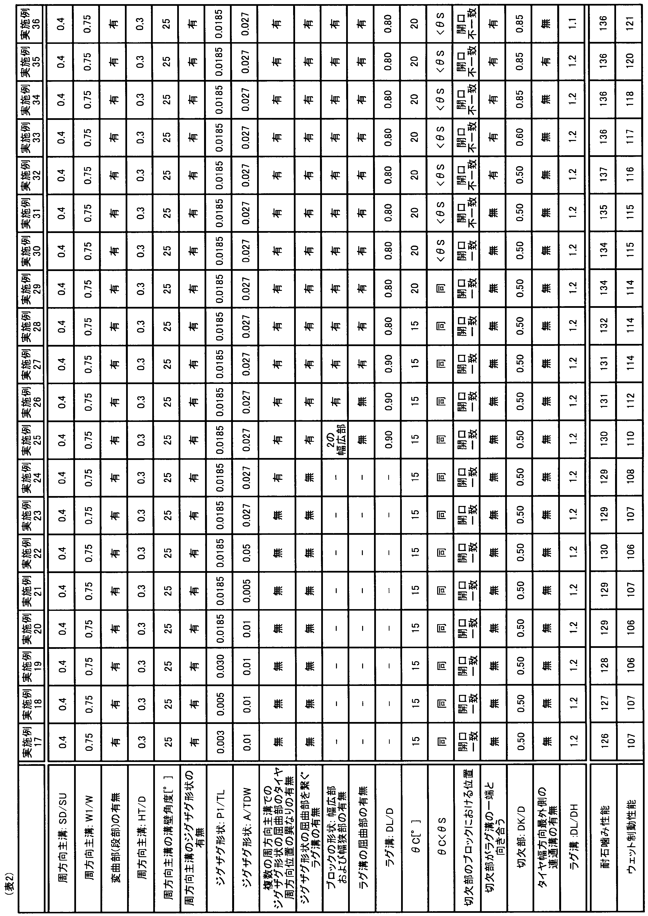
1 空気入りタイヤ
2 トレッド部
3 ショルダー部
4 サイドウォール部
5 ビード部
51 ビードコア
52 ビードフィラー
6 カーカス層
7 ベルト層
71、72、73、74 ベルト
20C、20S 陸部
21 トレッド面
22A 周方向主溝(内側周方向主溝)
22Aa 溝壁
22Ab 溝開口縁
22B 周方向主溝(外側周方向主溝)
22Ba 溝壁
22Bb 溝開口縁
221 溝底
222 段部
223 屈曲部
224 変曲部
225 突起
23Ki 切欠部(内側切欠部)
23Gi 浅溝部(内側浅溝部)
23Ko 切欠部(外側切欠部)
23Go 浅溝部(外側浅溝部)
23a 傾斜部
23b 底部
23c 開口部
24 ラグ溝
24a 屈曲部
25 切欠部
30 ラグ溝
BK ブロック
BKa 幅広部
BKb 幅狭部
CL タイヤ赤道面(タイヤ赤道線)
2 トレッド部
3 ショルダー部
4 サイドウォール部
5 ビード部
51 ビードコア
52 ビードフィラー
6 カーカス層
7 ベルト層
71、72、73、74 ベルト
20C、20S 陸部
21 トレッド面
22A 周方向主溝(内側周方向主溝)
22Aa 溝壁
22Ab 溝開口縁
22B 周方向主溝(外側周方向主溝)
22Ba 溝壁
22Bb 溝開口縁
221 溝底
222 段部
223 屈曲部
224 変曲部
225 突起
23Ki 切欠部(内側切欠部)
23Gi 浅溝部(内側浅溝部)
23Ko 切欠部(外側切欠部)
23Go 浅溝部(外側浅溝部)
23a 傾斜部
23b 底部
23c 開口部
24 ラグ溝
24a 屈曲部
25 切欠部
30 ラグ溝
BK ブロック
BKa 幅広部
BKb 幅狭部
CL タイヤ赤道面(タイヤ赤道線)
Claims (19)
- トレッド部のトレッド面にタイヤ周方向に延びる周方向主溝を有しており、前記周方向主溝は、子午断面において、各溝開口縁を結ぶ直線と平行な仮想区分線を溝深さの1/2位置に引いてタイヤ径方向外側とタイヤ径方向内側とに区分した場合に、タイヤ径方向外側の断面積SUと、タイヤ径方向内側の断面積SDとが、0.15≦SD/SU≦0.60の関係を満たす、空気入りタイヤ。
- 前記周方向主溝は、子午断面において、前記仮想区分線を溝深さの1/4位置に引いた場合に、当該1/4位置での溝幅W1と、溝開口部の溝幅Wとが、W1/W≦0.78の関係を満たす、請求項1に記載の空気入りタイヤ。
- 前記周方向主溝は、少なくとも一方の溝壁に、溝開口縁から溝底に向かって溝壁角度が変化する変曲部を有する、請求項1または2に記載の空気入りタイヤ。
- 前記周方向主溝は、溝底から前記変曲部までのタイヤ径方向の高さHTと、溝深さDとが、0.1≦HT/D≦0.5の関係を満たす、請求項3に記載の空気入りタイヤ。
- 前記周方向主溝は、溝壁の溝開口縁から溝底に向かう前記トレッド面の法線に対する溝壁角度が10°以上45°以下の範囲を満たす、請求項1~4のいずれか1つに記載の空気入りタイヤ。
- 前記周方向主溝は、タイヤ幅方向に振れるジグザグ形状を有する、請求項1~5のいずれか1つに記載の空気入りタイヤ。
- 前記周方向主溝は、前記ジグザグ形状の1周期のピッチ長P1と、タイヤ周方向のタイヤ周長TLとが、0.005≦P1/T≦0.03の関係を満たす、請求項6に記載の空気入りタイヤ。
- 前記周方向主溝は、前記ジグザグ形状の1周期の振幅Aと、タイヤ展開幅TDWとが、0.01≦A/TDW≦0.05の関係を満たす、請求項6または7に記載の空気入りタイヤ。
- 前記周方向主溝がタイヤ幅方向に複数並んで設けられており、
タイヤ幅方向で隣接する各前記周方向主溝において、前記ジグザグ形状の屈曲部の位置がタイヤ周方向で異なる、請求項6~8のいずれか1つに記載の空気入りタイヤ。 - 前記周方向主溝がタイヤ幅方向に複数並んで設けられており、
タイヤ幅方向で隣接する2本の前記周方向主溝に対し前記ジグザグ形状のタイヤ幅方向で最も近づく相互の屈曲部を繋ぎタイヤ周方向に複数並んで設けられたラグ溝と、
タイヤ幅方向で隣接する2本の前記周方向主溝とタイヤ周方向で隣接する2本の前記ラグ溝とで区画されたブロックと、
を有する、請求項6~9のいずれか1つに記載の空気入りタイヤ。 - 前記ブロックは、タイヤ周方向の中央に1つの幅広部を有しタイヤ周方向の両端にそれぞれ幅狭部を有する、請求項10に記載の空気入りタイヤ。
- 前記ラグ溝は、少なくとも2箇所に屈曲部を有する、請求項10または11に記載の空気入りタイヤ。
- 前記ラグ溝の溝深さDLと、当該ラグ溝が接続する前記周方向主溝の溝深さDとが、DL/D≦0.8の関係を満たす、請求項10~12のいずれか1つに記載の空気入りタイヤ。
- 前記ブロックを区画する一方の前記周方向主溝がタイヤ赤道面寄りに配置され、他方の前記周方向主溝がタイヤ接地端寄りに配置されており、
前記ブロックは、タイヤ幅方向両側において前記周方向主溝にそれぞれ接続して前記ブロックの内部で終端する切欠部を有し、
それぞれの前記切欠部は、それぞれの前記周方向主溝の溝底に向かって前記トレッド面の法線に対して傾斜する傾斜部を有し、
それぞれの前記傾斜部は、一方の前記周方向主溝の溝底に向かう傾斜角度θCと、他方の前記周方向主溝の溝底に向かう傾斜角度θSとが、θC≦20°、かつθC<θSの関係を満たす、請求項10~13のいずれか1つに記載の空気入りタイヤ。 - 前記ブロックは、タイヤ幅方向両側において前記周方向主溝にそれぞれ接続して前記ブロックの内部で終端する切欠部を有し、
それぞれの前記切欠部は、それぞれの前記周方向主溝に接続する開口部がタイヤ周方向でずれて配置され、各前記開口部の片方の縁同士がタイヤ周方向で一致する、請求項10~14のいずれか1つに記載の空気入りタイヤ。 - 前記ブロックは、タイヤ幅方向両側において前記周方向主溝にそれぞれ接続して前記ブロックの内部で終端する切欠部を有し、
前記切欠部は、前記周方向主溝を挟んで前記ラグ溝の一端と向き合って設けられている、請求項10~15のいずれか1つに記載の空気入りタイヤ。 - 前記切欠部のタイヤ径方向の最大高さDKと、当該切欠部が接続する前記周方向主溝の溝深さDとが、0.60≦DK/D≦0.85の関係を満たす、請求項14~16のいずれか1つに記載の空気入りタイヤ。
- 前記周方向主溝は、少なくとも前記ラグ溝が接続する側の溝壁に段部が形成されており、
前記ラグ溝の溝深さDLと、前記段部の前記トレッド面からの深さDHとが、DL/DH≦1.1の関係を満たす、請求項10~17のいずれか1つに記載の空気入りタイヤ。 - タイヤ幅方向最外側に設けられた前記周方向主溝のタイヤ幅方向外側に前記周方向主溝からタイヤ接地端に至り連続する溝を配置しない、請求項1~18のいずれか1つに記載の空気入りタイヤ。
Priority Applications (2)
| Application Number | Priority Date | Filing Date | Title |
|---|---|---|---|
| DE112019004945.3T DE112019004945T5 (de) | 2018-11-27 | 2019-08-23 | Luftreifen |
| US17/294,584 US12077017B2 (en) | 2018-11-27 | 2019-08-23 | Pneumatic tire |
Applications Claiming Priority (2)
| Application Number | Priority Date | Filing Date | Title |
|---|---|---|---|
| JP2018-221145 | 2018-11-27 | ||
| JP2018221145A JP7230459B2 (ja) | 2018-11-27 | 2018-11-27 | 空気入りタイヤ |
Publications (1)
| Publication Number | Publication Date |
|---|---|
| WO2020110387A1 true WO2020110387A1 (ja) | 2020-06-04 |
Family
ID=70852798
Family Applications (1)
| Application Number | Title | Priority Date | Filing Date |
|---|---|---|---|
| PCT/JP2019/033193 Ceased WO2020110387A1 (ja) | 2018-11-27 | 2019-08-23 | 空気入りタイヤ |
Country Status (4)
| Country | Link |
|---|---|
| US (1) | US12077017B2 (ja) |
| JP (1) | JP7230459B2 (ja) |
| DE (1) | DE112019004945T5 (ja) |
| WO (1) | WO2020110387A1 (ja) |
Families Citing this family (6)
| Publication number | Priority date | Publication date | Assignee | Title |
|---|---|---|---|---|
| JP7156337B2 (ja) * | 2020-06-16 | 2022-10-19 | 住友ゴム工業株式会社 | タイヤ |
| JP7793968B2 (ja) * | 2021-12-16 | 2026-01-06 | 住友ゴム工業株式会社 | タイヤ |
| JP2024066541A (ja) * | 2022-11-02 | 2024-05-16 | 住友ゴム工業株式会社 | 重荷重用タイヤ |
| CN115891512B (zh) * | 2022-11-29 | 2024-09-03 | 江苏通用科技股份有限公司 | 全钢子午线矿山轮胎花纹散热结构 |
| DE102023208002A1 (de) | 2023-08-22 | 2025-02-27 | Continental Reifen Deutschland Gmbh | Laufstreifen für einen Fahrzeugreifen |
| JP2025128544A (ja) * | 2024-02-22 | 2025-09-03 | 横浜ゴム株式会社 | 空気入りタイヤ |
Citations (12)
| Publication number | Priority date | Publication date | Assignee | Title |
|---|---|---|---|---|
| JPH06183212A (ja) * | 1992-12-22 | 1994-07-05 | Sumitomo Rubber Ind Ltd | 重車両用空気入りタイヤ |
| JP2001063316A (ja) * | 1999-09-01 | 2001-03-13 | Bridgestone Corp | 空気入りタイヤ |
| KR20050049220A (ko) * | 2003-11-21 | 2005-05-25 | 금호타이어 주식회사 | 스톤 이젝터의 상부면에 오목부가 형성된 공기입 레디얼타이어 |
| JP2008087626A (ja) * | 2006-10-02 | 2008-04-17 | Toyo Tire & Rubber Co Ltd | 空気入りタイヤ |
| JP2008137474A (ja) * | 2006-12-01 | 2008-06-19 | Toyo Tire & Rubber Co Ltd | 空気入りタイヤ |
| JP2013028202A (ja) * | 2011-07-26 | 2013-02-07 | Bridgestone Corp | 重荷重用空気入りタイヤ |
| JP2013043619A (ja) * | 2011-08-26 | 2013-03-04 | Yokohama Rubber Co Ltd:The | 空気入りタイヤ |
| WO2015003837A1 (de) * | 2013-07-11 | 2015-01-15 | Continental Reifen Deutschland Gmbh | Laufstreifenprofil eines fahrzeugluftreifens |
| DE102015202371A1 (de) * | 2015-02-10 | 2016-08-11 | Continental Reifen Deutschland Gmbh | Fahrzeugluftreifen |
| JP2017154708A (ja) * | 2016-03-04 | 2017-09-07 | 住友ゴム工業株式会社 | タイヤ |
| JP2018167664A (ja) * | 2017-03-29 | 2018-11-01 | 横浜ゴム株式会社 | 空気入りタイヤ |
| JP2019093907A (ja) * | 2017-11-22 | 2019-06-20 | 横浜ゴム株式会社 | 空気入りタイヤ |
Family Cites Families (12)
| Publication number | Priority date | Publication date | Assignee | Title |
|---|---|---|---|---|
| US2604920A (en) * | 1950-01-03 | 1952-07-29 | Firestone Tire & Rubber Co | Nontrap stone tread |
| JPS582844B2 (ja) * | 1978-06-29 | 1983-01-19 | 横浜ゴム株式会社 | 空気入りタイヤ |
| US4955416A (en) * | 1985-03-01 | 1990-09-11 | Sumitomo Rubber Industries, Ltd. | Pneumatic radial tire carcass profile |
| US4703788A (en) * | 1985-09-17 | 1987-11-03 | Sumitomo Rubber Industries, Ltd. | Tire tread with zig-zag grooves with projections in groove |
| JPH0717130B2 (ja) | 1988-02-23 | 1995-03-01 | 東洋ゴム工業株式会社 | 空気入りタイヤのトレッドパターン |
| US6481480B1 (en) * | 1996-06-07 | 2002-11-19 | The Goodyear Tire & Rubber Company | Convertible tread for a radial truck or trailer tire |
| JP4398700B2 (ja) * | 2003-10-31 | 2010-01-13 | 住友ゴム工業株式会社 | 空気入りタイヤ |
| JP4330561B2 (ja) * | 2005-07-12 | 2009-09-16 | 住友ゴム工業株式会社 | 重荷重用タイヤ |
| US7980281B2 (en) | 2006-10-02 | 2011-07-19 | Toyo Tire & Rubber Co., Ltd. | Pneumatic tire with tread having protruding stripe in groove bottom and tire mold for making the tire |
| US9469160B2 (en) * | 2009-01-26 | 2016-10-18 | Bridgestone Corporation | Tire with tread having blocks having cutout portions |
| JP2017024687A (ja) * | 2015-07-28 | 2017-02-02 | 住友ゴム工業株式会社 | 重荷重用空気入りタイヤ |
| JP6657750B2 (ja) * | 2015-10-14 | 2020-03-04 | 住友ゴム工業株式会社 | 空気入りタイヤ |
-
2018
- 2018-11-27 JP JP2018221145A patent/JP7230459B2/ja active Active
-
2019
- 2019-08-23 DE DE112019004945.3T patent/DE112019004945T5/de active Pending
- 2019-08-23 WO PCT/JP2019/033193 patent/WO2020110387A1/ja not_active Ceased
- 2019-08-23 US US17/294,584 patent/US12077017B2/en active Active
Patent Citations (12)
| Publication number | Priority date | Publication date | Assignee | Title |
|---|---|---|---|---|
| JPH06183212A (ja) * | 1992-12-22 | 1994-07-05 | Sumitomo Rubber Ind Ltd | 重車両用空気入りタイヤ |
| JP2001063316A (ja) * | 1999-09-01 | 2001-03-13 | Bridgestone Corp | 空気入りタイヤ |
| KR20050049220A (ko) * | 2003-11-21 | 2005-05-25 | 금호타이어 주식회사 | 스톤 이젝터의 상부면에 오목부가 형성된 공기입 레디얼타이어 |
| JP2008087626A (ja) * | 2006-10-02 | 2008-04-17 | Toyo Tire & Rubber Co Ltd | 空気入りタイヤ |
| JP2008137474A (ja) * | 2006-12-01 | 2008-06-19 | Toyo Tire & Rubber Co Ltd | 空気入りタイヤ |
| JP2013028202A (ja) * | 2011-07-26 | 2013-02-07 | Bridgestone Corp | 重荷重用空気入りタイヤ |
| JP2013043619A (ja) * | 2011-08-26 | 2013-03-04 | Yokohama Rubber Co Ltd:The | 空気入りタイヤ |
| WO2015003837A1 (de) * | 2013-07-11 | 2015-01-15 | Continental Reifen Deutschland Gmbh | Laufstreifenprofil eines fahrzeugluftreifens |
| DE102015202371A1 (de) * | 2015-02-10 | 2016-08-11 | Continental Reifen Deutschland Gmbh | Fahrzeugluftreifen |
| JP2017154708A (ja) * | 2016-03-04 | 2017-09-07 | 住友ゴム工業株式会社 | タイヤ |
| JP2018167664A (ja) * | 2017-03-29 | 2018-11-01 | 横浜ゴム株式会社 | 空気入りタイヤ |
| JP2019093907A (ja) * | 2017-11-22 | 2019-06-20 | 横浜ゴム株式会社 | 空気入りタイヤ |
Also Published As
| Publication number | Publication date |
|---|---|
| JP7230459B2 (ja) | 2023-03-01 |
| US20220009293A1 (en) | 2022-01-13 |
| JP2020083095A (ja) | 2020-06-04 |
| DE112019004945T5 (de) | 2021-06-17 |
| US12077017B2 (en) | 2024-09-03 |
Similar Documents
| Publication | Publication Date | Title |
|---|---|---|
| JP7230459B2 (ja) | 空気入りタイヤ | |
| US10195907B2 (en) | Heavy-duty tire | |
| JP5790166B2 (ja) | 空気入りタイヤ | |
| JP5915505B2 (ja) | 空気入りタイヤ | |
| US10603961B2 (en) | Pneumatic tire | |
| AU2016210113B2 (en) | Pneumatic tire | |
| JP6828496B2 (ja) | 空気入りタイヤ | |
| JP7098948B2 (ja) | 空気入りタイヤ | |
| CN113710503B (zh) | 充气轮胎 | |
| CN113710504B (zh) | 充气轮胎 | |
| JP7098959B2 (ja) | 空気入りタイヤ | |
| US11999199B2 (en) | Pneumatic tire | |
| WO2016088854A1 (ja) | 空気入りタイヤ | |
| CN110914073B (zh) | 充气轮胎 | |
| JP6798620B2 (ja) | 空気入りタイヤ | |
| AU2015331554B2 (en) | Pneumatic tire | |
| JP6631003B2 (ja) | 空気入りタイヤ | |
| JP7115150B2 (ja) | 空気入りタイヤ | |
| CN113573918B (zh) | 充气轮胎 | |
| JP6805535B2 (ja) | 空気入りタイヤ | |
| JP7139851B2 (ja) | 空気入りタイヤ | |
| CN109414963B (zh) | 充气轮胎 | |
| JP7069769B2 (ja) | 空気入りタイヤ | |
| JP5929143B2 (ja) | 空気入りタイヤ | |
| CN113453914A (zh) | 充气轮胎 |
Legal Events
| Date | Code | Title | Description |
|---|---|---|---|
| 121 | Ep: the epo has been informed by wipo that ep was designated in this application |
Ref document number: 19889874 Country of ref document: EP Kind code of ref document: A1 |
|
| 122 | Ep: pct application non-entry in european phase |
Ref document number: 19889874 Country of ref document: EP Kind code of ref document: A1 |