WO2020095571A1 - 天井吊下棚 - Google Patents
天井吊下棚 Download PDFInfo
- Publication number
- WO2020095571A1 WO2020095571A1 PCT/JP2019/038475 JP2019038475W WO2020095571A1 WO 2020095571 A1 WO2020095571 A1 WO 2020095571A1 JP 2019038475 W JP2019038475 W JP 2019038475W WO 2020095571 A1 WO2020095571 A1 WO 2020095571A1
- Authority
- WO
- WIPO (PCT)
- Prior art keywords
- shelf
- shaft
- ceiling
- link
- foup
- Prior art date
Links
Images


Classifications
-
- B—PERFORMING OPERATIONS; TRANSPORTING
- B61—RAILWAYS
- B61B—RAILWAY SYSTEMS; EQUIPMENT THEREFOR NOT OTHERWISE PROVIDED FOR
- B61B3/00—Elevated railway systems with suspended vehicles
- B61B3/02—Elevated railway systems with suspended vehicles with self-propelled vehicles
-
- B—PERFORMING OPERATIONS; TRANSPORTING
- B65—CONVEYING; PACKING; STORING; HANDLING THIN OR FILAMENTARY MATERIAL
- B65G—TRANSPORT OR STORAGE DEVICES, e.g. CONVEYORS FOR LOADING OR TIPPING, SHOP CONVEYOR SYSTEMS OR PNEUMATIC TUBE CONVEYORS
- B65G1/00—Storing articles, individually or in orderly arrangement, in warehouses or magazines
- B65G1/02—Storage devices
- B65G1/04—Storage devices mechanical
- B65G1/0457—Storage devices mechanical with suspended load carriers
-
- B—PERFORMING OPERATIONS; TRANSPORTING
- B61—RAILWAYS
- B61B—RAILWAY SYSTEMS; EQUIPMENT THEREFOR NOT OTHERWISE PROVIDED FOR
- B61B3/00—Elevated railway systems with suspended vehicles
-
- B—PERFORMING OPERATIONS; TRANSPORTING
- B65—CONVEYING; PACKING; STORING; HANDLING THIN OR FILAMENTARY MATERIAL
- B65G—TRANSPORT OR STORAGE DEVICES, e.g. CONVEYORS FOR LOADING OR TIPPING, SHOP CONVEYOR SYSTEMS OR PNEUMATIC TUBE CONVEYORS
- B65G1/00—Storing articles, individually or in orderly arrangement, in warehouses or magazines
- B65G1/02—Storage devices
-
- H—ELECTRICITY
- H01—ELECTRIC ELEMENTS
- H01L—SEMICONDUCTOR DEVICES NOT COVERED BY CLASS H10
- H01L21/00—Processes or apparatus adapted for the manufacture or treatment of semiconductor or solid state devices or of parts thereof
- H01L21/67—Apparatus specially adapted for handling semiconductor or electric solid state devices during manufacture or treatment thereof; Apparatus specially adapted for handling wafers during manufacture or treatment of semiconductor or electric solid state devices or components ; Apparatus not specifically provided for elsewhere
- H01L21/677—Apparatus specially adapted for handling semiconductor or electric solid state devices during manufacture or treatment thereof; Apparatus specially adapted for handling wafers during manufacture or treatment of semiconductor or electric solid state devices or components ; Apparatus not specifically provided for elsewhere for conveying, e.g. between different workstations
- H01L21/67703—Apparatus specially adapted for handling semiconductor or electric solid state devices during manufacture or treatment thereof; Apparatus specially adapted for handling wafers during manufacture or treatment of semiconductor or electric solid state devices or components ; Apparatus not specifically provided for elsewhere for conveying, e.g. between different workstations between different workstations
- H01L21/67706—Mechanical details, e.g. roller, belt
-
- H—ELECTRICITY
- H01—ELECTRIC ELEMENTS
- H01L—SEMICONDUCTOR DEVICES NOT COVERED BY CLASS H10
- H01L21/00—Processes or apparatus adapted for the manufacture or treatment of semiconductor or solid state devices or of parts thereof
- H01L21/67—Apparatus specially adapted for handling semiconductor or electric solid state devices during manufacture or treatment thereof; Apparatus specially adapted for handling wafers during manufacture or treatment of semiconductor or electric solid state devices or components ; Apparatus not specifically provided for elsewhere
- H01L21/677—Apparatus specially adapted for handling semiconductor or electric solid state devices during manufacture or treatment thereof; Apparatus specially adapted for handling wafers during manufacture or treatment of semiconductor or electric solid state devices or components ; Apparatus not specifically provided for elsewhere for conveying, e.g. between different workstations
- H01L21/67703—Apparatus specially adapted for handling semiconductor or electric solid state devices during manufacture or treatment thereof; Apparatus specially adapted for handling wafers during manufacture or treatment of semiconductor or electric solid state devices or components ; Apparatus not specifically provided for elsewhere for conveying, e.g. between different workstations between different workstations
- H01L21/67724—Apparatus specially adapted for handling semiconductor or electric solid state devices during manufacture or treatment thereof; Apparatus specially adapted for handling wafers during manufacture or treatment of semiconductor or electric solid state devices or components ; Apparatus not specifically provided for elsewhere for conveying, e.g. between different workstations between different workstations by means of a cart or a vehicule
-
- H—ELECTRICITY
- H01—ELECTRIC ELEMENTS
- H01L—SEMICONDUCTOR DEVICES NOT COVERED BY CLASS H10
- H01L21/00—Processes or apparatus adapted for the manufacture or treatment of semiconductor or solid state devices or of parts thereof
- H01L21/67—Apparatus specially adapted for handling semiconductor or electric solid state devices during manufacture or treatment thereof; Apparatus specially adapted for handling wafers during manufacture or treatment of semiconductor or electric solid state devices or components ; Apparatus not specifically provided for elsewhere
- H01L21/677—Apparatus specially adapted for handling semiconductor or electric solid state devices during manufacture or treatment thereof; Apparatus specially adapted for handling wafers during manufacture or treatment of semiconductor or electric solid state devices or components ; Apparatus not specifically provided for elsewhere for conveying, e.g. between different workstations
- H01L21/67703—Apparatus specially adapted for handling semiconductor or electric solid state devices during manufacture or treatment thereof; Apparatus specially adapted for handling wafers during manufacture or treatment of semiconductor or electric solid state devices or components ; Apparatus not specifically provided for elsewhere for conveying, e.g. between different workstations between different workstations
- H01L21/6773—Conveying cassettes, containers or carriers
-
- H—ELECTRICITY
- H01—ELECTRIC ELEMENTS
- H01L—SEMICONDUCTOR DEVICES NOT COVERED BY CLASS H10
- H01L21/00—Processes or apparatus adapted for the manufacture or treatment of semiconductor or solid state devices or of parts thereof
- H01L21/67—Apparatus specially adapted for handling semiconductor or electric solid state devices during manufacture or treatment thereof; Apparatus specially adapted for handling wafers during manufacture or treatment of semiconductor or electric solid state devices or components ; Apparatus not specifically provided for elsewhere
- H01L21/677—Apparatus specially adapted for handling semiconductor or electric solid state devices during manufacture or treatment thereof; Apparatus specially adapted for handling wafers during manufacture or treatment of semiconductor or electric solid state devices or components ; Apparatus not specifically provided for elsewhere for conveying, e.g. between different workstations
- H01L21/67763—Apparatus specially adapted for handling semiconductor or electric solid state devices during manufacture or treatment thereof; Apparatus specially adapted for handling wafers during manufacture or treatment of semiconductor or electric solid state devices or components ; Apparatus not specifically provided for elsewhere for conveying, e.g. between different workstations the wafers being stored in a carrier, involving loading and unloading
- H01L21/67769—Storage means
-
- B—PERFORMING OPERATIONS; TRANSPORTING
- B65—CONVEYING; PACKING; STORING; HANDLING THIN OR FILAMENTARY MATERIAL
- B65G—TRANSPORT OR STORAGE DEVICES, e.g. CONVEYORS FOR LOADING OR TIPPING, SHOP CONVEYOR SYSTEMS OR PNEUMATIC TUBE CONVEYORS
- B65G2201/00—Indexing codes relating to handling devices, e.g. conveyors, characterised by the type of product or load being conveyed or handled
- B65G2201/02—Articles
- B65G2201/0297—Wafer cassette
-
- H—ELECTRICITY
- H01—ELECTRIC ELEMENTS
- H01L—SEMICONDUCTOR DEVICES NOT COVERED BY CLASS H10
- H01L21/00—Processes or apparatus adapted for the manufacture or treatment of semiconductor or solid state devices or of parts thereof
- H01L21/67—Apparatus specially adapted for handling semiconductor or electric solid state devices during manufacture or treatment thereof; Apparatus specially adapted for handling wafers during manufacture or treatment of semiconductor or electric solid state devices or components ; Apparatus not specifically provided for elsewhere
- H01L21/677—Apparatus specially adapted for handling semiconductor or electric solid state devices during manufacture or treatment thereof; Apparatus specially adapted for handling wafers during manufacture or treatment of semiconductor or electric solid state devices or components ; Apparatus not specifically provided for elsewhere for conveying, e.g. between different workstations
- H01L21/67703—Apparatus specially adapted for handling semiconductor or electric solid state devices during manufacture or treatment thereof; Apparatus specially adapted for handling wafers during manufacture or treatment of semiconductor or electric solid state devices or components ; Apparatus not specifically provided for elsewhere for conveying, e.g. between different workstations between different workstations
- H01L21/67733—Overhead conveying
Definitions
- the present invention mainly relates to a ceiling suspension shelf for a ceiling carrier to temporarily put articles.
- Patent Document 1 discloses a transfer system including a ceiling transfer vehicle and a shelf of this type.
- the ceiling guided vehicle of Patent Document 1 includes an elevating device for lowering an article and a lateral transfer device for laterally moving the article.
- the shelves of Patent Document 1 are supported by columns and arranged in a plurality of rows vertically.
- the ceiling carrier can place the article on the shelf by lowering the article by the elevating device to match the height of a predetermined shelf and then laterally moving the article.
- Patent Document 1 In a factory that manufactures semiconductor products as disclosed in Patent Document 1, there is a possibility that a structure capable of storing more items will be required as the processing speed of the processing device increases. Further, not only in a factory that manufactures semiconductor products, but also in various buildings in which ceiling guided vehicles are arranged, similarly, a configuration capable of storing a larger number of articles may be required.
- the present invention has been made in view of the above circumstances, and its main purpose is to provide a ceiling hanging shelf for placing an article at a position where the article could not be placed conventionally.
- the ceiling suspension shelf is a shelf in which a ceiling carrier that travels in a suspended state along a rail provided on the ceiling of a building and transports an article temporarily puts the article transported to a target position. It is hung from the ceiling.
- the ceiling hanging shelf includes an upper shelf including an upper supporting surface that supports the article. The height of the upper support surface is substantially the same as the height of the rail.
- the upper shelf is in an open state in which the article going from below to above the upper shelf can pass, and the article passing from below to above can pass the article. It is preferable to provide a switching mechanism for switching between a closed state in which it cannot be closed.
- the switching mechanism switches between the open state and the closed state by transmitting a driving force from the outside.
- the above-mentioned ceiling suspension shelf preferably has the following configuration. That is, the upper shelf includes a first shaft, a first support part, a second shaft, and a second support part.
- the first shaft is rotatable.
- the first support portion rotates integrally with the first shaft.
- the second shaft is rotatable and has a center position different from that of the first shaft.
- the second support portion rotates integrally with the second shaft.
- the switching mechanism transmits an external driving force to the first shaft as a rotational force, and an external driving force to the second shaft as a rotational force in a direction opposite to the first shaft, The open state and the closed state are switched.
- the drive system can be simplified. Further, if the first shaft and the second shaft are rotated in the same direction, the first support portion rotates upward and the second support portion rotates downward, and as a result, the vertical direction of the upper shelf 62 at the time of state switching is changed. The occupied space becomes large. On the other hand, by rotating the first shaft and the second shaft in different directions, the first support portion and the second support portion move vertically in the same direction, so that the occupied space in the vertical direction can be suppressed.
- the switching mechanism has a connection link mechanism that connects the first shaft and the second shaft.
- the connection link mechanism includes a first connection link and a second connection link.
- the first connecting link is located on the first shaft side.
- the second connecting link is located on the second shaft side, is connected to the first connecting link, and rotates in a direction opposite to the first connecting link.
- the switching mechanism includes a first shaft link, a second shaft link, and a connecting link.
- the first shaft link rotates integrally with the first shaft.
- the second shaft link rotates integrally with the second shaft.
- the connection link connects the first shaft link and the second shaft link such that the first shaft link and the second shaft link rotate in different directions.
- first shaft and the second shaft can be rotated mainly in different directions by using one connecting link, so that the mechanism can be simplified.
- the switching mechanism includes a first pulley, a first belt, a first gear, a second gear, a second pulley, and a second belt.
- the first belt is wound around the first pulley and rotates the first shaft.
- the first gear rotates integrally with the first pulley in the same direction.
- the second gear rotates in the opposite direction to the first gear by meshing with the first gear directly or through an even number of gears.
- the second pulley rotates integrally with the second gear in the same direction.
- the second belt is wound around the second pulley and rotates the second shaft.
- the switching mechanism includes a connecting belt, a first reel, and a second reel.
- the first reel rotates integrally with the first shaft, and the connection belt is wound.
- the second reel rotates integrally with the second shaft, and the connecting belt is wound in the same direction as the first reel.
- the first reel is rotated by the driving force from the outside and the connecting belt is wound around the first reel, the second reel is rotated in the opposite direction to the first reel.
- the second reel is rotated by the driving force from the outside and the connection belt is wound around the second reel, the first reel is rotated in the opposite direction to the second reel.
- this ceiling hanging shelf includes, in addition to the upper shelf, a lower shelf that overlaps with the upper shelf in plan view.
- the lower shelf is arranged below the upper shelf.
- the lower shelf is configured so that the articles cannot pass vertically.
- the shelves can be placed above and below, so that the space inside the building can be used more effectively.
- the number of articles that can be placed on one section of the upper shelf is smaller than the number of articles that can be placed on one section of the lower shelf.
- the above-mentioned ceiling suspension shelf preferably has the following configuration. That is, the article is a wafer transfer container that transfers wafers.
- the upper shelf includes an insertion pin formed on the upper support surface and inserted into a recess in the bottom surface of the wafer transfer container.
- the upper shelf is provided with the insertion pin, so that the attitude of the wafer transfer container can be stabilized.
- the above-mentioned ceiling suspension shelf preferably has the following configuration. That is, the target position is a place for placing the wafer transfer container with respect to the processing apparatus that processes the wafer.
- the upper shelf is arranged at a position higher than the target position.
- the upper shelf is arranged on both sides so as to sandwich the rail.
- the ceiling hanging shelf includes the upper side surface guide arranged so as to face the side surface of the article supported by the upper shelf.
- the upper side guide is disposed at a position higher than the lower end of the rail.
- a fall prevention unit for preventing the fall of the article is arranged on the back surface when the surface facing the rail is the front surface.
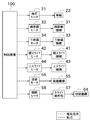
- FIG. 3 is a block diagram mainly showing a configuration of a drive unit and the like provided in a ceiling guided vehicle.
- the front view which shows the structure of the lower shelf transfer part of a ceiling carrier.
- the perspective view which shows the structure of the retracting mechanism provided in the bottom face side of FOUP.
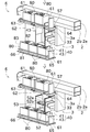
- FIG. 6 is a perspective view showing how the upper shelf is switched from the closed state to the open state.
- FIG. 6 is a perspective view showing a state in which the lateral slide mechanism and the upper slide mechanism of the upper shelf transfer unit are operated.
- the perspective view which shows a mode that FOUP is put on an upper shelf.
- the block diagram which shows the structure of a drive part etc. which are provided in the ceiling guided vehicle of 2nd Embodiment.
- the front view which shows a mode that the upper shelf transfer part of 2nd Embodiment is operated.
- the front view which shows the ceiling suspension shelf of 3rd Embodiment roughly.
- the schematic front view which shows the flow which the upper shelf of 4th Embodiment switches from a closed state to an open state.
- the schematic front view which shows the flow which the upper shelf of 5th Embodiment switches from a closed state to an open state.
- the schematic front view which shows the flow which the upper shelf of 6th Embodiment switches from a closed state to an open state.
- the schematic front view which shows the flow which the upper stage shelf of 7th Embodiment switches from a closed state to an open state.
- FIG. 1 is a plan view schematically showing the configuration of the transfer system 1 according to the first embodiment.
- the transport system 1 of the present embodiment is a system for transporting various items, which is installed in a factory (building, facility) that manufactures semiconductor products.
- the article carried by the carrying system 1 of the present embodiment is a FOUP (Front-Opening Unified Pod) that contains a wafer (semiconductor wafer).
- the article may be a reticle pod that houses a reticle.
- the transfer system 1 includes a rail 2, a ceiling transfer vehicle 3, and a ceiling suspension shelf 6.
- Rail 2 is installed on the ceiling 7 of the factory.
- the ceiling transport vehicle 3 is configured to be able to travel along the rail 2 in a suspended state. Although only one ceiling guided vehicle 3 is shown in FIG. 1, a plurality of ceiling guided vehicles 3 may be provided.
- the processing unit 4 and the load port 5 are arranged in this factory.
- the processing apparatus 4 is an apparatus that performs various processes on the wafer accommodated in the FOUP.
- the load port 5 is connected to the space where the processing device 4 performs processing.
- the FOUP transported by the ceiling transport vehicle 3 is placed on the load port 5.
- the wafer in the FOUP is processed by the processing apparatus 4 after being taken out.
- the processed wafer is stored in the FOUP, and the FOUP is transferred to the position where another process is performed by the same or another ceiling transfer vehicle 3.
- the load port 5 may be arranged below the ceiling suspension shelf 6, or the load port 5 or a temporary storage shelf (not shown) may be arranged below the rail 2.
- the ceiling suspension shelf 6 is installed on the ceiling 7 of the factory. When the processing device 4 and the load port 5 which are the target positions are occupied (in use), the ceiling suspension shelf 6 temporarily holds FOUPs and the like until these are released from occupancy (usable). It is a shelf for keeping.
- the ceiling hanging shelf 6 is arranged parallel to the rail 2 so as to extend along the longitudinal direction of the rail 2. Although the ceiling suspension shelves 6 of this embodiment are arranged on both sides of the rail 2, they may be arranged on only one side.
- FIGS. 2 to 6 the rail 2, the ceiling carrier 3, and the ceiling suspension shelf 6 will be described in detail with reference to FIGS. 2 to 6. It should be noted that in the perspective views of FIG. 3 and the like, illustration of the ceiling suspension shelf 6 arranged on one side of the rail 2 and a fall prevention portion 67 described later is omitted.
- columns 8 are connected to the ceiling 7 of the factory.
- the rail 2 and the ceiling suspension shelf 6 are suspended on the ceiling 7 by the pillars 8.
- the ceiling carrier 3 is suspended from the ceiling 7 via the columns 8 and the rails 2.
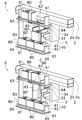
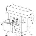
- the ceiling hanging shelf 6 includes a side plate 61, an upper shelf (first shelf) 62, and a lower shelf (second shelf) 65.
- the side plate 61 is suspended from the ceiling 7 by the above-mentioned pillar 8.
- the side plate 61 supports the upper shelf 62 and the lower shelf 65. Further, the side plates 61 are arranged at regular intervals, and the space sandwiched by the two side plates 61 corresponds to one section.
- the ceiling hanging shelf 6 is configured such that a plurality of sections having the same configuration are continuous.
- the upper shelf 62 of this embodiment two FOUPs 80 can be placed in one section.
- the upper shelf 62 is arranged at a position higher than the lower shelf 65.
- the height of the upper support surface 62a (first support surface in FIG. 2) of the upper shelf 62 that supports the FOUP 80 is substantially the same as the height of the rail 2.
- the height of the upper support surface 62a is between the height near the lower end and the height near the upper end of the rail 2.
- the heights of the upper support surface 62 a are “substantially the same”, a case where the height of the upper support surface 62 a is slightly lower than the lower end of the rail 2 and a case where the height of the upper support surface 62 a is slightly higher than the upper end of the rail 2 are included.
- the height at which the upper support surface 62a supports the FOUP 80 is higher than the height at which the moving ceiling carrier 3 supports the FOUP 80, and is higher than the height at which the load port 5 supports the FOUP 80.
- the height of the upper support surface 62a is higher than the upper end of the lower shelf transfer section 30 described later.
- the upper stage support surface 62 a is different in position in the horizontal direction from the ceiling transport vehicle 3 and is arranged at a position higher than the ceiling transport vehicle 3.
- the ceiling hanging shelf 6 includes an upper side surface guide 63 arranged so as to face the side surface 83 of the FOUP 80.
- the upper side surface guide 63 is arranged at a position higher than the lower end of the rail 2. It should be noted that the upper side guide 63 need only be set at a position higher than the upper support surface 62a, and need not necessarily be positioned higher than the lower end of the rail 2.
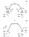
- the upper shelf 62 is configured to be opened and closed by rotating around a predetermined rotation axis.
- the upper shelf 62 has an open state (chain line in FIG. 5) in which the upper shelf 62 can be positioned outside to allow the FOUP 80 to pass from below, and the upper shelf 62 can be positioned inside to open the openings. It is possible to realize a closed state in which the FOUP 80 is supported by closing some or all of them.
- the ceiling hanging shelf 6 includes a switching mechanism 64 (FIGS. 3 and 4) for switching between the open state and the closed state of the upper shelf 62.
- the switching mechanism 64 is configured by gears and links that transmit the power transmitted from the outside.
- the ceiling suspension shelf 6 does not have a drive unit for switching the state of the upper shelf 62, and the open / closed state of the upper shelf 62 is switched by the power transmitted from the ceiling transport vehicle 3.
- the ceiling guided vehicle 3 includes a slide operation unit 57 that operates the switching mechanism 64.
- the slide operation part (operation part) 57 is driven by an opening / closing motor (drive part) 58.
- the slide operation part 57 is configured to be able to change its position between a normal position and a pressing position.
- the slide operating portion 57 is in the normal position, the slide operating portion 57 is not in contact with the switching mechanism 64, and the upper shelf 62 is closed.
- the slide operating portion 57 is in the pressed position, the slide operating portion 57 operates the switching mechanism 64 to switch the upper shelf 62 to the open state.
- the upper shelf 62 is rotated to switch between the open state and the closed state, but the upper shelf 62 may be slid to switch between the open state and the closed state.
- the ceiling hanging shelf 6 may be configured to include a drive unit for switching the state of the upper shelf 62.
- the lower shelf 65 of this embodiment three FOUPs 80 can be placed in one section.
- the lower shelves 65 can have a larger number of FOUPs 80 in one section (in other words, per unit length) than the upper shelves 62.
- the lower shelf 65 is arranged at a position lower than the upper shelf 62. Specifically, the height at which the lower support surface 65a (second support surface) of the lower shelf 65 supports the FOUP 80 is lower than the height at which the moving ceiling carrier 3 supports the FOUP 80, and the load port 5 supports the FOUP 80. Higher than supporting height.
- the upper end of the FOUP 80 supported by the lower support surface 65a is more than the lower end of the upper shelf transfer part 40 described later (more specifically, the lower end of the upper shelf transfer part 40 after being moved in the lateral direction). Down below.
- the lower shelf 65 is always closed, and unlike the upper shelf 62, the state cannot be switched. In other words, the lower shelf 65 is configured so that it cannot pass through the FOUP 80 vertically. As a specific structure, the lower shelf 65 is a shelf plate that connects adjacent side plates 61.
- the ceiling suspension shelf 6 includes a lower side surface guide 66 arranged so as to face the side surface 83 of the FOUP 80.
- the ceiling hanging shelf 6 includes a fall prevention unit 67.
- the fall prevention unit 67 is a net, a fence, a flat plate, or the like.
- the fall prevention unit 67 is provided on the surface (rear surface) of the ceiling suspension shelf 6 that is opposite to the surface facing the rail 2 (ceiling carrier 3).
- the fall prevention portion 67 is provided in a portion far from the rail 2 in the direction orthogonal to the rail 2 in plan view.
- the fall prevention unit 67 prevents the FOUP 80 from falling by contacting the FOUP 80 when the FOUP 80 placed on the upper shelf 62 or the lower shelf 65 moves or falls toward the side away from the rail 2.
- the fall prevention unit 67 of the present embodiment is arranged so as to cover from the lower end to the upper end of the FOUP 80 placed on the upper shelf 62 or the lower shelf 65 in order to reliably prevent the FOUP 80 from falling. In other words, when viewed in a direction perpendicular to the surface of the fall prevention unit 67, the entire FOUP 80 overlaps the fall prevention unit 67. Further, in the present embodiment, the fall prevention unit 67 covers from the lower end of the upper shelf 62 to the upper end of the FOUP 80 placed on the lower shelf 65, but may be divided into the upper shelf 62 side and the lower shelf 65 side. ..
- the fall prevention unit 67 is arranged on the opposite side of the ceiling guided vehicle 3 with the FOUP 80 placed on the upper shelf 62 or the lower shelf 65 interposed therebetween. Therefore, even if the FOUP 80 that is being placed on the upper shelf 62 or the lower shelf 65 from the ceiling transport vehicle 3 contacts the already placed FOUP 80, it is possible to prevent the placed FOUP 80 from falling.
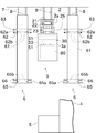
- the rail 2 includes a traveling rail 2a and a power feeding rail 2b.
- the traveling rail 2a is provided with a traveling support surface for supporting the ceiling guided vehicle 3 (wheels 22 to be described later in detail) and allowing the ceiling guided vehicle 3 to travel.
- the power supply rail 2b is arranged below the traveling rail 2a.
- a power supply line (not shown) is arranged on the power supply rail 2b and supplies electric power to the ceiling guided vehicle 3.
- the ceiling guided vehicle 3 includes a traveling motor 21, wheels 22, and a power receiving unit 23 as a configuration for traveling along the rail 2.
- the traveling motor 21 is arranged in the traveling rail 2a.
- the traveling motor 21 generates power for traveling the ceiling guided vehicle 3.
- the wheels 22 are arranged in contact with the traveling support surface of the traveling rail 2a.
- the wheels 22 are rotationally driven by the traveling motor 21.
- the power receiving unit 23 is arranged inside the power feeding rail 2b.
- the power receiving unit 23 is a pickup coil or the like that acquires electric power from the power supply line of the power supply rail 2b, and supplies the electric power acquired from the power supply line to electric equipment such as the traveling motor 21.
- the control device 100 is configured as a computer provided at an appropriate position on the ceiling guided vehicle 3.
- the control device 100 includes an arithmetic device such as a CPU, a storage device such as a flash memory or a hard disk, and an input / output unit for communicating with the outside.
- Various programs and setting values are stored in the storage device.
- the arithmetic device reads out various programs from the storage device and controls the operation of each part of the ceiling guided vehicle 3.
- the ceiling guided vehicle 3 includes a pair of covers 3a arranged side by side in the front-rear direction.
- the structure for holding or transferring the FOUP 80 is arranged between the pair of covers 3a.
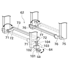
- the ceiling guided vehicle 3 includes a chuck (second holding unit) 51 and a holding base (first holding unit) 52 as a configuration for holding the FOUP 80.
- the chuck 51 holds and holds the flange portion 82 on the upper surface of the FOUP 80.
- the chuck 51 can switch whether to hold the flange portion 82.
- the holding table 52 holds the bottom surface 81 of the FOUP 80. Specifically, as shown in FIGS. 5, 6, 9 and the like, a plurality of insertion pins 52b are formed at predetermined positions on the holding surface 52a (the surface that contacts the bottom surface 81) of the holding table 52. On the other hand, on the bottom surface 81 of the FOUP 80, as shown in FIG. 6, a recess 81a having a predetermined shape is formed. The positions of the plurality of insertion pins 52b and the shape of the recess 81a correspond to each other. With this structure, the FOUP 80 can be stably held by inserting the insertion pin 52b into the recess 81a. A guide member 53 is provided near the holding table 52 to prevent the FOUP 80 from being displaced.
- the FOUP 80 is held by the holding table 52 while the ceiling guided vehicle 3 is running. Note that, in the following description, a position where the traveling overhead conveying vehicle 3 holds the FOUP 80 is referred to as a holding position. By holding the FOUP 80 by the holding table 52, the FOUP 80 can be stabilized.
- the FOUP 80 may be held by both the chuck 51 and the holding table 52 or only the chuck 51 while the ceiling guided vehicle 3 is traveling.
- the ceiling guided vehicle 3 moves the FOUP 80 in the holding position to the lower shelf 65 (lower transfer position) to move the lower shelf transfer unit (second transfer unit) 30 and the FOUP 80 in the holding position to the upper stage.
- An upper shelf transfer section (first transfer section) 40 that is moved to be placed on the shelf 62 (upper transfer position).
- the lower shelf transfer unit 30 is also used to place the FOUP 80 on the load port 5.
- the lower shelf transfer unit 30 can move the chuck 51 laterally (horizontal direction) (third movement) and also can move the chuck 51 downward (fourth movement). ..
- the lower shelf transfer unit 30 includes a horizontal transfer mechanism 31 and a lower transfer mechanism 33. Further, as shown in FIG. 4, the horizontal transfer mechanism 31 is driven by the horizontal transfer motor 32, and the lower transfer mechanism 33 is driven by the lower transfer motor 34.
- the lateral transfer mechanism 31 is configured to be able to move the chuck 51 in the lateral direction (specifically, the direction orthogonal to the traveling direction in plan view). Specifically, the lateral transfer mechanism 31 includes a plurality of movable plates that can move in the lateral direction. Further, the chuck 51 is configured to move integrally with the lowermost movable plate. The lateral transfer mechanism 31 slides a plurality of movable plates in the lateral direction by the power of the lateral transfer motor 32 to move the chuck 51 supported by the lateral transfer mechanism 31 in the lateral direction. Move to. This allows the FOUP 80 to move laterally.
- the horizontal transfer mechanism 31 moves upward when the horizontal transfer mechanism 31 moves in the horizontal direction. It does not come into contact with the shelf 62 or the FOUP 80 supported by the upper shelf 62.
- the lower transfer mechanism 33 is configured so that the chuck 51 can be moved downward.
- the lower transfer mechanism 33 is, for example, a hoist, and can lower or wind a hanging member such as a wire by the power of the lower transfer motor 34 as shown in FIG. As a result, the FOUP 80 can be moved in the vertical direction.
- the lower transfer mechanism 33 is configured to move integrally with the lowermost movable plate of the horizontal transfer mechanism 31. Therefore, it is possible to achieve both the lateral movement by the lateral transfer mechanism 31 and the downward movement by the lower transfer mechanism 33. Therefore, the lower shelf transfer unit 30 can transfer the FOUP 80 not only when the transfer position is right below and right next to the transfer position but also diagonally below.
- the holding table 52 is detached from the FOUP 80 before the FOUP 80 is moved by the lower shelf transfer section 30, and the FOUP 80 is moved from below the FOUP 80 (specifically, the lower shelf transfer section 30 uses the chuck 51.
- the holding table 52 is retracted (from the locus of moving downward).
- the ceiling guided vehicle 3 includes a retraction mechanism 55 and a retraction motor 56 as shown in FIG.
- the retracting mechanism 55 includes a link operated by the power of the retracting motor 56. Further, this link is rotatably connected to the guide member 53. Further, the holding table 52 is configured to move integrally with the guide member 53 along a predetermined locus. As described above, by operating the link of the retracting mechanism 55 by the power of the retracting motor 56, the holding table 52 and the guide member 53 are moved to the rear of the FOUP 80, so that the FOUP 80 can be retracted from below. A temporary shelf (UTB, Under Track Buffer) suspended from the ceiling 7 below the rail 2 may be added.
- UTB Under Track Buffer
- the temporary shelf is located at a position where it overlaps with the rail 2 in a plan view, and is installed so as to be out of phase with the load port 5 in the direction in which the rail 2 extends.
- the second transfer section can transfer the FOUP 80 to this temporary storage shelf.
- the FOUP 80 is held by the holding table 52 and is not held by the chuck 51 while the ceiling guided vehicle 3 is traveling. Therefore, when the ceiling guided vehicle 3 is stopped and the FOUP 80 is transferred to the lower shelf 65 or the load port 5, after the FOUP 80 is held by the chuck 51, the retract motor 56 is driven to remove the holding table 52 from the FOUP 80. Then, the transfer is performed by the lower shelf transfer unit 30.
- the upper shelf transfer section 40 is provided in the space between the cover 3a and the FOUP 80 in the traveling direction.
- the upper shelf transfer unit 40 can move the holding table 52 laterally (first movement) and can move the holding table 52 upward (second movement).
- first movement only needs to include the lateral direction in the moving direction, and includes directions other than the true lateral direction.
- second movement only needs to include the lateral direction in the moving direction, and includes directions other than the true lateral direction.
- the upper shelf transfer unit 40 includes a lateral slide mechanism 41 and an upper slide mechanism 43. Further, as shown in FIG. 4, the horizontal slide mechanism 41 is driven by the horizontal slide motor 42, and the upper slide mechanism 43 is driven by the upper slide motor 44.
- the lateral slide mechanism 41 is configured to be able to move the holding table 52 in the lateral direction (specifically, the direction orthogonal to the traveling direction in plan view).
- the lateral slide mechanism 41 includes a plurality of movable plates that can move in the lateral direction.
- the lateral slide mechanism 41 is three movable plates connected to each other by a belt or a chain.
- the holding table 52 is configured to move integrally with the innermost movable plate.
- the horizontal slide mechanism 41 moves the holding table 52 supported by the horizontal slide mechanism 41 in the horizontal direction by sliding the plurality of movable plates in the horizontal direction as shown in FIG. 8 by the power of the horizontal slide motor 42. Let This allows the FOUP 80 to move laterally.
- the upper slide mechanism 43 is configured so that the holding table 52 can be moved upward.
- the upper slide mechanism 43 includes a plurality of movable plates that can move upward.
- the holding table 52 is configured to move integrally with the innermost movable plate.
- the upper slide mechanism 43 moves the holding table 52 supported by the upper slide mechanism 43 upward by sliding the plurality of movable plates upward as shown in FIG. 8 by the power of the upper slide motor 44.
- the FOUP 80 can be moved upward.
- the FOUP 80 is transferred to the upper shelf 62 with the upper slide mechanism 43 positioned on the side surface of the FOUP 80. Therefore, in order to avoid interference between the upper slide mechanism 43 and another FOUP 80, it is necessary to widen the interval between the upper shelves 62. Therefore, the upper shelves 62 and the lower shelves 65 differ in the number of FOUPs 80 that can be arranged in one section.
- the ceiling guided vehicle 3 stops beside the upper shelf 62 of the transfer destination (the upper side in FIG. 7).
- the ceiling guided vehicle 3 moves the slide operation portion 57 to the pressing position to switch the upper shelf 62 from the closed state to the opened state (lower side in FIG. 7). Note that, unlike the present embodiment, when the traveling overhead traveling vehicle 3 holds the FOUP 80 only by the chuck 51, the chuck 51 is removed and the holding table 52 is used to hold the FOUP 80.
- the ceiling guided vehicle 3 operates the lateral slide mechanism 41 to move the FOUP 80 laterally (upper side in FIG. 8). At this time, the FOUP 80 is located directly below the upper shelf 62.
- the ceiling guided vehicle 3 operates the upper slide mechanism 43 to move the FOUP 80 upward (lower side in FIG. 8). At this time, the FOUP 80 is located above the upper transfer position in order to properly rotate the upper shelf 62.
- the upward movement by the upper slide mechanism 43 is performed after the lateral movement by the lateral slide mechanism 41 is completed, but the upward movement is started before the lateral movement is completed. May be.
- the lower end of the upper shelf transfer unit 40 after moving in the horizontal direction is above the upper end of the FOUP 80 supported by the lower shelf 65 (further, If it is in a position that overlaps in plan view). Therefore, the horizontal slide mechanism 41 and the FOUP 80 mounted on the lower shelf 65 are prevented from interfering with each other.
- the ceiling guided vehicle 3 moves the slide operation part 57 to the normal position to switch the upper shelf 62 from the open state to the closed state (upper side in FIG. 9).
- the ceiling guided vehicle 3 starts the operation of storing the upper slide mechanism 43 and the lateral slide mechanism 41 in the ceiling guided vehicle 3 (lower side in FIG. 9).
- the FOUP 80 is located at a high position (the same height as the rail 2 in this embodiment). Can be placed. Therefore, it is possible to effectively use the space in the factory, specifically, the space right next to the rail 2 that has not been effectively used so far.
- the transport system 1 of the present embodiment is particularly effective in a factory for manufacturing semiconductor products.
- all of the plurality of ceiling transfer vehicles 3 constituting the transfer system 1 may be configured to include the upper shelf transfer section 40, or only some of the ceiling transfer vehicles 3 may transfer to the upper shelf transfer section 40.
- the configuration may include 40.
- the upper shelf transfer unit 40 includes a horizontal slide mechanism 41 and a horizontal slide motor 42.
- the upper shelf transfer unit 90 of the second embodiment is an arm mechanism including a plurality of arms that are rotatably connected.
- the upper shelf transfer section 90 includes a first arm 91, a second arm 93, and a third arm 95 in order from the side closer to the ceiling transport vehicle 3.
- the first arm 91 is driven by the first arm motor 92
- the second arm 93 is driven by the second arm motor 94
- the third arm 95 is driven by the third arm motor 96. It In this way, each arm can operate independently.
- the base end of the first arm 91 is connected to the ceiling carrier 3, and the tip end of the first arm 91 is rotatably connected to the base end of the second arm 93.
- the tip of the second arm 93 is rotatably connected to the base end of the third arm 95.
- the first holding portion 97 is connected to the tip of the third arm 95.
- the rotation angles of the first arm 91, the second arm 93, and the third arm 95 should be adjusted as shown in FIG.
- the first holding portion 97 can be moved to the upper shelf 62 while keeping the first holding portion 97 horizontal.
- the first holding portion 97 mainly moves in the lateral direction (first movement). , Top of FIG. 11).
- the first holding portion 97 mainly moves upward (second movement, lower side of FIG. 11).
- the upper shelf transfer unit 40 moves the FOUP 80 with the insertion pin 52b of the holding table 52 inserted in the recess 81a of the FOUP 80.
- the insertion pins 62b (FIG. 12) may be formed on the upper support surface 62a of the upper shelf 62. By inserting the insertion pin 62b into the recess 81a of the FOUP 80, the posture of the FOUP 80 placed on the upper shelf 62 can be stabilized.
- the lower shelf 65 may also be formed with the insertion pin 65b on the lower support surface 65a, and the insertion pin 65b may be inserted into the recess 81a of the FOUP 80.
- a first recess into which the insertion pin 52b of the holding table 52 is inserted, and a second recess into which the insertion pin 62b of the upper shelf 62 (or the insertion pin 65b of the lower shelf 65) is inserted May be formed respectively. Accordingly, the posture of the FOUP 80 can be stabilized both during the upper transfer of the FOUP 80 and after the upper transfer.
- the features of the first to third embodiments can be combined as appropriate.
- the fall prevention unit 67 of the first embodiment can be applied to the second embodiment or the third embodiment.
- the fourth to seventh embodiments will be described with reference to FIGS. 13 to 18.
- the fourth to seventh embodiments are configured to supply a driving force to the upper shelf 62 by using a rotation operation section (operation section) 59 instead of the slide operation section 57.
- a rotation operation section operation section
- FIGS. 13 and 14 the configuration common to the fourth to seventh embodiments will be described with reference to FIGS. 13 and 14.
- the ceiling guided vehicle 3 of these embodiments includes a motor mounting portion 45 in addition to the opening / closing motor 58 and the rotation operation portion 59 described above.
- the motor attachment portion 45 is attached to the upper shelf transfer portion 40. More specifically, it is a portion of the upper shelf transfer unit 40 that moves during the first movement in which the holding table 52 (FOUP 80) is moved in the lateral direction and that moves the holding table 52 in the upper direction. It is attached to the part that does not move when moving. With this configuration, the rotation operation unit 59 moves laterally during the first movement.
- the motor mounting portion 45 is mounted on only one side in the traveling direction, but may be mounted on both sides.
- An opening / closing motor 58 and a rotation operation part 59 are attached to the motor attachment part 45.
- the opening / closing motor 58 generates a driving force for switching between the open state and the closed state of the upper shelf 62, as in the above embodiment.
- the opening / closing motor 58 is configured to be able to control the rotation direction and the rotation amount.
- the rotation operating section 59 is a member that rotates by the driving force generated by the opening / closing motor 58.
- the rotation operation part 59 transmits this driving force to the upper shelf 62 side, similarly to the slide operation part 57.
- the motor mounting portion 45, the opening / closing motor 58, and the rotation operation portion 59 are arranged at a position that does not interfere with the second movement of the upper slide mechanism 43 (for example, outside the upper slide mechanism 43).
- the opening / closing motor 58 and the rotation operation unit 59 are arranged side by side in the direction orthogonal to both the traveling direction and the vertical direction (horizontal direction).
- the opening / closing motor 58 and the rotation operating part 59 on one side in the left-right direction are used when the FOUP 80 is transferred to the upper shelf 62 on the one side in the left-right direction, and the opening / closing motor 58 and the rotation operating part 59 on the other side in the left-right direction are It is used when the FOUP 80 is transferred to the upper shelf 62 on the other side in the left-right direction.
- the common opening / closing motor 58 and the rotation operation unit 59 may be used when the FOUP 80 is transferred to either the upper shelf 62 on one side or the other side in the left-right direction.
- the upper shelf 62 includes a first shaft 71, a first arm 72, a first support portion 73, a second shaft 75, a second arm 76, and a second support portion 77. Equipped with.
- the first shaft 71 is rotatably attached to a fixed portion (a non-movable portion, such as the side plate 61 of the above embodiment) of the upper shelf 62.
- the first arm 72 is configured to rotate integrally with the first shaft 71 in the same direction.
- the first shaft 71 is fixed to one end of the first arm 72, and the first support portion 73 is fixed to the other end of the first arm 72.
- the first shaft 71 and the first arm 72 are provided as a pair.
- the upper shelf 62 includes a first support portion 73 that connects the pair of first arms 72.
- the first support portion 73 is a portion that supports the FOUP 80.
- the first support portion 73 may have a rod shape or a flat plate shape.
- the second shaft 75, the second arm 76, and the second support portion 77 have the same or symmetrical configuration as the first shaft 71, the first arm 72, and the first support portion 73. Therefore, the FOUP 80 is supported by the first support portion 73 and the second support portion 77.
- the upper shelf 62 can be switched between the closed state (solid line) and the open state (chain line).
- the driving force transmitted from the ceiling guided vehicle 3 (the driving force from the outside of the upper shelf 62) is used to rotate the first shaft 71 and the second shaft 75.
- the first shaft 71 and the second shaft 75 may be rotated in the same direction for the purpose of simplifying the switching mechanism 64 and the like.
- the driving force transmitted from the ceiling guided vehicle 3 is a member that constitutes the switching mechanism 64, that is, the receiving portion 101, the receiving shaft 102, the first bevel gear 103, the second bevel gear 104, Is transmitted to the first shaft 71 via.
- the receiving portion 101 is configured to be rotatable around a receiving shaft 102 as a rotation axis.
- the receiving portion 101 is arranged at a position corresponding to the rotation operation portion 59 after the first movement. With this configuration, by rotating the rotation operating portion 59 after the first movement, the receiving portion 101 and the receiving shaft 102 rotate according to the rotation direction and the rotation amount of the rotation operating portion 59.
- a first bevel gear 103 is further fixed to the receiving shaft 102.
- the second bevel gear 104 is fixed to the first shaft 71.
- the first bevel gear 103 and the second bevel gear 104 mesh with each other.
- the driving force can be transmitted from the rotation operation unit 59 to the first shaft 71 via the first bevel gear 103, the second bevel gear 104, and the like.
- the rotation direction of the opening / closing motor 58 the rotation direction of the first shaft 71 can be changed.
- the transmission of the driving force using the receiving portion 101, the receiving shaft 102, the first bevel gear 103, and the second bevel gear 104 is an example, and can be changed as appropriate.
- the driving force for rotating the first shaft 71 is further transmitted to the second shaft 75 by the switching mechanism 64, and the second shaft 75 is rotated in the direction opposite to the first shaft 71. Accordingly, the first shaft 71 and the second shaft 75 can be driven by using one drive unit to switch the upper shelf 62 from the open state to the closed state.
- the specific configuration of the switching mechanism 64 differs depending on the embodiment.
- the opening / closing motor 58 by rotating the opening / closing motor 58 in the opposite direction, the first shaft 71 and the second shaft 75 rotate in the opposite direction from the time of switching from the open state to the closed state.
- the upper shelf 62 can be switched from the closed state to the open state.
- the process of rotating the second shaft 75 using the other rotation operation unit 59 is performed. That is, only in the seventh embodiment, a configuration corresponding to the receiving portion 101, the receiving shaft 102, the first bevel gear 103, and the second bevel gear 104 is provided not only on the first shaft 71 but also on the second shaft 75. ..
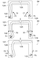
- the switching mechanism 64 of the fourth embodiment includes a link support portion 111 and a connecting link mechanism 110.
- the link support portion 111 supports the first shaft 71, the second shaft 75, the connection link mechanism 110, etc.
- the link support portion 111 includes the first shaft 71, the second shaft 75, the connection link mechanism 110, etc. Do not follow.
- connection link mechanism 110 is a mechanism that connects the first shaft 71 and the second shaft 75.
- the connection link mechanism 110 includes a first connection link 112, a first shaft link 113, an auxiliary link 114, a common link 115, a second connection link 116, a second shaft link 117, and an auxiliary link 118.
- the first connecting link 112 is connected to the first shaft link 113, the auxiliary link 114, and the common link 115.
- the first shaft link 113 is fixed to the first shaft 71 via a through hole formed in the link support portion 111 and rotates integrally with the first shaft 71. Therefore, when the first shaft 71 is driven, the first connecting link 112 also moves.
- the auxiliary link 114 is attached to the link support portion 111.
- the common link 115 is inserted into the elongated hole-shaped opening 112a formed in the first connecting link 112.
- the first shaft link 113, the auxiliary link 114, and the common link 115 all have the same radius of gyration. Therefore, the first connecting link 112 moves without changing its direction (moves in parallel).
- the second connecting link 116 is connected to the second shaft link 117, the auxiliary link 118, and the common link 115.
- the second connecting link 116, the second shaft link 117, and the auxiliary link 118 are line-symmetrical to the first connecting link 112, the first shaft link 113, and the auxiliary link 114.
- a line that passes through the midpoint of the line segment connecting the first shaft 71 and the second shaft 75 and is orthogonal to this line segment is the line-symmetric reference line.
- the common link 115 is inserted into the opening 116 a of the second connecting link 116.
- the second connecting link 116 operates by transmitting the driving force via the common link 115.
- the auxiliary link 118 and the second shaft link 117 rotate.
- the movements of the second connecting link 116, the second shaft link 117, and the auxiliary link 118 are line-symmetrical to the first connecting link 112, the first shaft link 113, and the auxiliary link 114 with the above-described reference line as a reference. Therefore, the rotation direction of the first shaft 71 and the rotation direction of the second shaft 75 are different.
- the connecting portion between the first connecting link 112 and the first shaft link 113 is at a position lower than the first shaft 71 and inside the first shaft 71.
- the connection point between the second connecting link 116 and the second shaft link 117 is also a position lower than the second shaft 75 and a position inside the second shaft 75. Therefore, when an upward force is applied to both the first shaft link 113 and the second shaft link 117, the first shaft link 113 and the second shaft link 117 rotate upward so as to pass through the inside (that is, , Rotate in different directions).
- connection link mechanism 110 it is possible to rotate the second shaft 75 to the other side only by rotating the first shaft 71 to the one side.
- the first support portion 73 and the second support portion 77 can be rotated outward as shown in FIG. 15, so that the upper shelf 62 can be switched from the closed state to the open state.
- the upper shelf 62 can be switched from the open state to the closed state by rotating the first shaft 71 in another direction.
- first connecting link 112 is a substantially L-shaped member, and includes a portion (a portion extending upward) retracted upward from a connection portion with the first shaft link 113.
- second connecting link 116 is a space formed around the line segment connecting the first shaft 71 and the second shaft 75. This prevents the upper shelf 62 and the ceiling carrier 3 from interfering with each other.
- the structure for retracting the first connecting link 112 and the second connecting link 116 upward is not necessary.
- the rotation operation unit 59 separates from the upper shelf 62 after switching the state of the upper shelf 62. Therefore, the upper shelf 62 may be provided with a stopper or the like that maintains the current state (maintains the state until a certain force is applied).
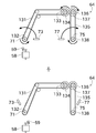
- first shaft link 113 and the second shaft link 117 are connected via two links (the first connecting link 112 and the second connecting link 116).
- first shaft link 122 and the second shaft link 123 are connected by one link (connection link 124).
- connection link 124 The first shaft link 122 and the second shaft link 123 have the same configuration as in the fourth embodiment.
- the connecting link 124 is rotatably connected to the first shaft 71 on the side of the first shaft 71 and rotatably connected to the second shaft link 123 on the side of the second shaft 75. Further, the connection link 124 has a configuration retracted upward as in the fourth embodiment. Further, the connection link 124 is supported by the link support portion 121 via the first shaft link 122 or the second shaft link 123, as in the fourth embodiment. Further, a swing stop plate 125 for preventing the connecting link 124 from swinging in the axial direction such as the first shaft 71 is fixed to the link support portion 121.
- the anti-skid plate 125 does not normally restrain the connecting link 124, and only when the connecting link 124 largely moves in the axial direction of the first shaft 71 or the like, it comes into contact with the connecting link 124 and further movement is prevented. To prevent.
- the first shaft link 122 integrally rotates in the same direction.
- the connecting link 124 also operates, which causes the second shaft link 123 to rotate.
- the second shaft 75 rotates in the direction opposite to the first shaft 71.
- the first shaft 71 and the second shaft 75 may rotate in the same direction depending on the shape of the connecting link 124 and the connecting point.
- the second shaft 75 rotates in the direction opposite to the first shaft 71 due to the transmission of the driving force from the first shaft 71.
- the rotation of the first shaft 71 causes the connection portion between the first shaft link 122 and the connection link 124 to rotate inward below the first shaft 71.
- This driving force is transmitted to the second shaft link 123 via the connecting link 124. Since the connecting portion between the second shaft link 123 and the connecting link 124 is located above the second shaft 75, it rotates upward above the second shaft 75 toward the outside. As a result, the first shaft 71 and the second shaft 75 rotate in different directions.
- the second shaft 75 can be rotated to the other side only by rotating the first shaft 71 to the one side.
- the first support portion 73 and the second support portion 77 can be rotated outward, so that the upper shelf 62 can be switched from the closed state to the open state.
- the upper shelf 62 can be switched from the open state to the closed state by rotating the first shaft 71 in another direction.
- the driving force is transmitted from the first shaft 71 to the second shaft 75 with a configuration including a belt and a pulley.
- the switching mechanism 64 of the sixth embodiment includes a first belt 131, a second belt 135.
- the first belt 131 is wound around the drive pulley 132 and the first pulley 133.
- the drive pulley 132 is fixed to the first shaft 71 and rotates integrally with the first shaft 71.
- the first belt 131 moves using the rotation of the first shaft 71 as a driving force.
- the first pulley 133 is arranged between the first shaft 71 and the second shaft 75 and at a position higher than the first shaft 71 and the second shaft 75. That is, like the fourth and fifth embodiments, a part of the switching mechanism 64 is retracted upward.
- the switching mechanism 64 also includes a first gear 134 that rotates integrally with the first pulley 133. That is, by rotating the first shaft 71, the first gear 134 can be rotated.
- the first gear 134 meshes with the second gear 136 arranged in the vicinity thereof. Therefore, the second gear 136 rotates in the opposite direction to the first gear 134.
- the switching mechanism 64 includes a second pulley 137 that rotates integrally with the second gear 136.
- the second belt 135 is wound around the second pulley 137 and the driven pulley 138.
- the driven pulley 138 is fixed to the second shaft 75 and rotates integrally with the second shaft 75.
- the second shaft 75 can be rotated. Further, the second shaft 75 rotates in the direction opposite to the first shaft 71 by interposing the first gear 134 and the second gear 136 on the way. As a result, as shown in FIG. 17, the first support portion 73 and the second support portion 77 can be rotated outward, so that the upper shelf 62 can be switched from the closed state to the open state. Similarly, the upper shelf 62 can be switched from the open state to the closed state by rotating the first shaft 71 in another direction.
- the first gear 134 and the second gear 136 are directly meshed with each other, but they may be meshed with an even number of gears.
- the switching mechanism 64 of the seventh embodiment transmits the driving force by using the rotation of the reel when winding the belt.
- the switching mechanism 64 includes a connecting belt 141, a first reel 142, and a second reel 143.
- the first reel 142 is configured so that the connecting belt 141 can be wound around it.
- the first reel 142 is fixed to the first shaft 71 and rotates integrally with the first shaft 71. Therefore, the connecting belt 141 can be wound by rotating the first shaft 71 in the first direction using the rotation operating portion 59.
- the connecting belt 141 is wound around the second reel 143 after retracting upward from the first reel 142. That is, as in the fourth to sixth embodiments, a part of the switching mechanism 64 is retracted upward.
- the second reel 143 is configured so that the connecting belt 141 can be wound around it.
- the second reel 143 is fixed to the second shaft 75 and rotates integrally with the second shaft 75.
- the first reel 142 and the second reel 143 have the same direction in which the connecting belt 141 is wound. Therefore, the rotation direction of the first reel 142 for winding the connection belt 141 and the rotation direction of the second reel 143 for pulling out the connection belt 141 are different.
- the second reel 143 rotates in the direction in which the connecting belt 141 is pulled out. That is, the first shaft 71 and the second shaft 75 rotate in different directions.
- the connecting belt 141 does not always wind around the second reel 143. Therefore, the driving force of the first shaft 71 is not transmitted to the second shaft 75. Therefore, in the seventh embodiment, in addition to the rotary operation part 59 for driving the first shaft 71, a rotary operation part 59 for driving the second shaft 75 is further provided. Further, as described above, the receiving portion 101, the receiving shaft 102, the first bevel gear 103, the second bevel gear 104, and the like are provided between the rotation operation portion 59 and the second shaft 75.
- the second shaft 75 can be rotationally driven.
- the rotation operating portion 59 rotates the second shaft 75 and the second reel 143 rotates in the direction in which the connection belt 141 is wound, whereby the connection belt 141 is removed from the first reel 142. Since it is pulled out, the connecting belt 141 can be rotated. Even in this case, the rotation directions of the first shaft 71 and the second shaft 75 are different. As a result, the first support portion 73 and the second support portion 77 can be rotated outward, so that the upper shelf 62 can be switched from the closed state to the open state.
- the rotation operation unit 59 rotates the first shaft 71 and the first reel 142 rotates in the direction in which the coupling belt 141 is wound, whereby the upper shelf 62 can be switched from the open state to the closed state.
- the ceiling suspension shelf 6 travels in a suspended state along the rails 2 provided on the ceiling 7 of the building and transports the FOUP 80 by the ceiling transport vehicle 3 at the target position (load port 5). It is a shelf on which the FOUP 80 to be transported to is temporarily placed and is hung from the ceiling 7.
- the ceiling hanging shelf 6 includes an upper shelf 62 including an upper support surface 62a that supports the FOUP 80. The height of the upper support surface 62a is substantially the same as the height of the rail 2.
- the upper shelf 62 has an open state in which the FOUP 80 that goes upward from below the upper shelf 62 can pass, and the FOUP 80 that can support the FOUP 80 and goes upward from below. Is provided with a switching mechanism 64 for switching between a closed state in which the vehicle cannot pass.
- the FOUP 80 can be placed from below on the upper shelf 62 at a high position, the operation of placing the FOUP 80 can be simplified.
- the switching mechanism 64 switches between the open state and the closed state by transmitting the driving force from the outside (ceiling carrier 3).
- the upper shelf 62 includes a first shaft 71, a first support portion 73, a second shaft 75, and a second support portion 77. ..
- the first shaft 71 is rotatable.
- the first support portion 73 rotates integrally with the first shaft 71.
- the second shaft 75 is rotatable and differs from the first shaft 71 in the axial center position.
- the second support portion 77 rotates integrally with the second shaft 75.
- the switching mechanism 64 transmits a driving force from the outside to the first shaft 71 as a rotational force, and transmits a driving force from the outside to the second shaft 75 as a rotational force in a direction opposite to the first shaft 71, Switch between open and closed states.
- the drive system can be simplified. Further, if the first shaft 71 and the second shaft 75 are rotated in the same direction, the first support portion 73 rotates upward and the second support portion 77 rotates downward, resulting in a larger occupied space in the vertical direction. .. On the other hand, by rotating the first shaft 71 and the second shaft 75 in different directions, the first support portion 73 and the second support portion 77 operate in the same vertical direction, thus suppressing the occupied space in the vertical direction. be able to.
- the switching mechanism 64 has a connection link mechanism 110 that connects the first shaft 71 and the second shaft 75.
- the connection link mechanism 110 includes a first connection link 112 and a second connection link 116.
- the first connecting link 112 is located on the first shaft 71 side.
- the second connecting link 116 is located on the second shaft 75 side, is connected to the first connecting link 112, and rotates in the opposite direction to the first connecting link 112.
- the switching mechanism 64 includes a first shaft link 122, a second shaft link 123, and a connecting link 124.
- the first shaft link 122 rotates integrally with the first shaft link 122.
- the second shaft link 123 rotates integrally with the second shaft 75.
- the connection link 124 connects the first shaft link 122 and the second shaft link 123 so that the first shaft link 122 and the second shaft link 123 rotate in different directions.
- first shaft link 122 and the second shaft link 123 can be rotated mainly in one connecting link 124 in different directions, so that the mechanism can be simplified.
- the switching mechanism 64 includes the first pulley 133, the first belt 131, the first gear 134, the second gear 136, the second pulley 137, and the second pulley 137. And two belts 135.
- the first belt 131 is wound around the first pulley 133 and rotates the first shaft 71.
- the first gear 134 rotates integrally with the first pulley 133 in the same direction.
- the second gear 136 rotates in the opposite direction to the first gear 134 by meshing with the first gear 134.
- the second pulley 137 rotates integrally with the second gear 136 in the same direction.
- the second belt 135 winds around the second pulley 137 and rotates the second shaft 75.
- first shaft 71 and the second shaft 75 can be rotated in different directions by using the belt and the pulley.
- the switching mechanism 64 includes a connecting belt 141, a first reel 142, and a second reel 143.
- the first reel 142 rotates integrally with the first shaft 71, and the connection belt 141 is wound.
- the second reel 143 rotates integrally with the second shaft 75, and the connecting belt 141 is wound in the same direction as the first reel 142.
- the first reel 142 is rotated by the driving force from the outside and the coupling belt 141 is wound around the first reel
- the second reel 143 is rotated in the opposite direction to the first reel 142.
- the first reel 142 rotates in the opposite direction to the second reel 143.
- the ceiling hanging shelf 6 of the above embodiment includes, in addition to the upper shelf 62, a lower shelf 65 overlapping the upper shelf 62 in a plan view.
- the lower shelf 65 is arranged below the upper shelf 62.
- the lower shelf 65 is configured so that the FOUP 80 cannot pass vertically.
- the shelves can be placed above and below, so that the space inside the building can be used more effectively.
- the number of FOUPs 80 that can be placed on the upper shelf 62 of one section is smaller than the number of FOUPs 80 that can be placed on the lower shelf 65 of one section.
- the FOUP 80 is a wafer transfer container that transfers wafers.
- the upper shelf 62 is formed on the upper support surface 62a and includes an insertion pin 62b that is inserted into the recess 81a of the bottom surface 81 of the FOUP 80.
- the upper shelf 62 is provided with the insertion pin 62b, so that the posture of the FOUP 80 can be stabilized.
- the target position is a place (load port 5) for placing the FOUP 80 with respect to the processing apparatus 4 that processes the wafer.
- the upper shelf 62 is arranged at a position higher than the target position.
- the upper shelves 62 are arranged on both sides of the rail 2 so as to sandwich the rail 2.
- the ceiling hanging shelf 6 of the above-described embodiment is provided with an upper side surface guide 63 which is arranged so as to face the side surface 83 of the FOUP 80 supported by the upper shelf 62.
- the upper side surface guide 63 is arranged at a position higher than the lower end of the rail 2.
- the upper shelf 62 can be arranged at a relatively high position.
- a fall prevention unit 67 that prevents the FOUP 80 from falling is arranged on the back surface when the surface facing the rail 2 is the front surface.
- the FOUP 80 when the FOUP 80 is transferred to the ceiling hanging shelf 6, for example, the FOUP 80 can be more reliably prevented from falling.
- the ceiling hanging shelf 6 includes the upper shelf 62 and the lower shelf 65, but the ceiling hanging shelf 6 may have only the upper shelf 62.
- two FOUPs 80 can be arranged on the upper shelf 62 of one section and three FOUPs 80 can be arranged on the lower shelf 65 of one section, but a different number of FOUPs 80 can be arranged. May be Further, the number of FOUPs 80 that can be arranged on the upper shelves 62 and the lower shelves 65 may be the same, or the upper shelves 62 may be larger.
- the upper shelf transfer unit 40 transfers the FOUP 80 to the upper shelf 62 by performing the first movement for lateral movement and the second movement for upward movement.
- the method of moving the FOUP 80 may be different from the above. For example, before the first movement, the FOUP 80 may be moved slightly downward to separate the FOUP 80 from the ceiling guided vehicle 3.
- At least one of the chuck 51 and the holding table 52 may be configured to hold a side surface (including a protruding portion formed on the side surface) of the FOUP 80.
- the slide operation unit 57 of the first embodiment applies a driving force by linear motion to the switching mechanism 64
- the rotation operation unit 59 of the fourth to seventh embodiments applies a driving force by rotational motion to the switching mechanism 64.
- These are the supply of the driving force by contact, but the operation unit may be configured to supply the driving force by non-contact using, for example, a magnet gear.
- the transfer system 1 installed in a factory that manufactures semiconductor products has been described, but the transfer system 1 can also be installed in a factory that manufactures other products.
- the transport system 1 can also be installed in a building (for example, a warehouse) other than the manufacturing factory.
Landscapes
- Engineering & Computer Science (AREA)
- Physics & Mathematics (AREA)
- Condensed Matter Physics & Semiconductors (AREA)
- General Physics & Mathematics (AREA)
- Manufacturing & Machinery (AREA)
- Computer Hardware Design (AREA)
- Microelectronics & Electronic Packaging (AREA)
- Power Engineering (AREA)
- Mechanical Engineering (AREA)
- Transportation (AREA)
- Warehouses Or Storage Devices (AREA)
- Container, Conveyance, Adherence, Positioning, Of Wafer (AREA)
Abstract
Description
3 天井搬送車
6 天井吊下棚
30 下段棚用移載部
40 上段棚用移載部
51 チャック
52 保持台
62 上段棚
62a 上段支持面
63 上段側面ガイド
65 下段棚
65a 下段支持面
66 下段側面ガイド
80 FOUP(ウエハ搬送容器)
90 上段棚用移載部
97 第1保持部
Claims (15)
- 建屋の天井に設けられるレールに沿って吊下げ状態で走行して物品を搬送する天井搬送車が、目標位置に搬送される前記物品を一時的に置く棚であって、天井から吊り下げられた天井吊下棚において、
前記物品を支持する上段支持面を含む上段棚を備え、
前記上段支持面の高さは、前記レールの高さと略同じであることを特徴とする天井吊下棚。 - 請求項1に記載の天井吊下棚であって、
前記上段棚は、当該上段棚の下方から上方へ向かう前記物品が通過可能な開口状態と、前記物品を支持可能であるとともに下方から上方へ向かう前記物品が通過できない閉鎖状態と、を切り替える切替機構を備えることを特徴とする天井吊下棚。 - 請求項2に記載の天井吊下棚であって、
前記切替機構は、外部からの駆動力が伝達されることで、前記開口状態と前記閉鎖状態とを切り替えることを特徴とする天井吊下棚。 - 請求項3に記載の天井吊下棚であって、
前記上段棚は、
回転可能な第1軸と、
前記第1軸と一体的に回転する第1支持部と、
回転可能であって前記第1軸とは軸中心の位置が異なる第2軸と、
前記第2軸と一体的に回転する第2支持部と、
を備え、
前記切替機構は、外部からの駆動力を前記第1軸に回転力として伝達し、外部からの駆動力を前記第2軸に前記第1軸とは反対方向の回転力として伝達することで、前記開口状態と前記閉鎖状態とを切り替えることを特徴とする天井吊下棚。 - 請求項4に記載の天井吊下棚であって、
前記切替機構は、
前記第1軸と前記第2軸を連結する連結リンク機構を有しており、
前記連結リンク機構は、
前記第1軸側に位置する第1連結リンクと、
前記第2軸側に位置し、前記第1連結リンクと連結しており、前記第1連結リンクとは反対方向に回転する第2連結リンクと、
を備えることを特徴とする天井吊下棚。 - 請求項4に記載の天井吊下棚であって、
前記切替機構は、
前記第1軸と一体的に回転する第1軸リンクと、
前記第2軸と一体的に回転する第2軸リンクと、
前記第1軸リンクと前記第2軸リンクが異なる方向に回転するように、前記第1軸リンクと前記第2軸リンクを連結する連結リンクと、
を備えることを特徴とする天井吊下棚。 - 請求項4に記載の天井吊下棚であって、
前記切替機構は、
第1プーリと、
前記第1プーリに巻き掛けられるとともに前記第1軸を回転させる第1ベルトと、
前記第1プーリと一体的に同方向に回転する第1歯車と、
前記第1歯車と直接又は偶数個の歯車を介して噛み合うことで、前記第1歯車とは反対方向に回転する第2歯車と、
前記第2歯車と一体的に同方向に回転する第2プーリと、
前記第2プーリに巻き掛けられるとともに前記第2軸を回転させる第2ベルトと、
を備えることを特徴とする天井吊下棚。 - 請求項4に記載の天井吊下棚であって、
前記切替機構は、
連結ベルトと、
前記第1軸と一体的に回転し、前記連結ベルトが巻かれた第1リールと、
前記第2軸と一体的に回転し、前記第1リールと同じ向きに前記連結ベルトが巻かれた第2リールと、
を備え、
外部からの駆動力で前記第1リールが回転して当該第1リールに前記連結ベルトが巻き付けられた場合は、前記第1リールと反対方向に前記第2リールが回転し、
外部からの駆動力で前記第2リールが回転して当該第2リールに前記連結ベルトが巻き付けられた場合は、前記第2リールと反対方向に前記第1リールが回転することを特徴とする天井吊下棚。 - 請求項1から8までの何れか一項に記載の天井吊下棚であって、
前記上段棚に加え、平面視で前記上段棚と重なる下段棚を備え、
前記下段棚は、前記上段棚よりも下方に配置されており、
前記下段棚は、前記物品が上下に通過できないように構成されていることを特徴とする天井吊下棚。 - 請求項9に記載の天井吊下棚であって、
1区画の前記上段棚に前記物品を置くことができる数は、1区画の前記下段棚に前記物品を置くことができる数よりも少ないことを特徴とする天井吊下棚。 - 請求項1から10までの何れか一項に記載の天井吊下棚であって、
前記物品は、ウエハを搬送するウエハ搬送容器であり、
前記上段棚は、前記上段支持面に形成されており前記ウエハ搬送容器の底面の凹部に挿入される挿入ピンを備えることを特徴とする天井吊下棚。 - 請求項11に記載の天井吊下棚であって、
前記目標位置は、前記ウエハを処理する処理装置に対して前記ウエハ搬送容器を置くための場所であり、
前記上段棚は、前記目標位置よりも高い位置に配置されていることを特徴とする天井吊下棚。 - 請求項1から12までの何れか一項に記載の天井吊下棚であって、
前記上段棚は、前記レールを挟むように両側に配置されることを特徴とする天井吊下棚。 - 請求項1から13までの何れか一項に記載の天井吊下棚であって、
前記上段棚に支持される前記物品の側面に対向するように配置される上段側面ガイドを備え、
前記レールの下端より高い位置に前記上段側面ガイドが配置されていることを特徴とする天井吊下棚。 - 請求項1から14までの何れか一項に記載の天井吊下棚であって、
前記レールを向く面を正面とした場合における背面に、前記物品の落下を防止する落下防止部が配置されることを特徴とする天井吊下棚。
Priority Applications (5)
| Application Number | Priority Date | Filing Date | Title |
|---|---|---|---|
| KR1020217007402A KR102480674B1 (ko) | 2018-11-06 | 2019-09-30 | 천장 매달림 선반 |
| JP2020556681A JP7095750B2 (ja) | 2018-11-06 | 2019-09-30 | 天井吊下棚 |
| US17/289,790 US11952213B2 (en) | 2018-11-06 | 2019-09-30 | Ceiling suspended shelf |
| CN201980070544.6A CN112912321B (zh) | 2018-11-06 | 2019-09-30 | 顶棚悬吊搁板 |
| EP19881592.0A EP3858763B1 (en) | 2018-11-06 | 2019-09-30 | Ceiling-hung shelf |
Applications Claiming Priority (2)
| Application Number | Priority Date | Filing Date | Title |
|---|---|---|---|
| JP2018208652 | 2018-11-06 | ||
| JP2018-208652 | 2018-11-06 |
Publications (1)
| Publication Number | Publication Date |
|---|---|
| WO2020095571A1 true WO2020095571A1 (ja) | 2020-05-14 |
Family
ID=70611986
Family Applications (1)
| Application Number | Title | Priority Date | Filing Date |
|---|---|---|---|
| PCT/JP2019/038475 WO2020095571A1 (ja) | 2018-11-06 | 2019-09-30 | 天井吊下棚 |
Country Status (6)
| Country | Link |
|---|---|
| US (1) | US11952213B2 (ja) |
| EP (1) | EP3858763B1 (ja) |
| JP (2) | JP7095750B2 (ja) |
| KR (1) | KR102480674B1 (ja) |
| CN (1) | CN112912321B (ja) |
| WO (1) | WO2020095571A1 (ja) |
Cited By (1)
| Publication number | Priority date | Publication date | Assignee | Title |
|---|---|---|---|---|
| CN106697821A (zh) * | 2016-12-27 | 2017-05-24 | 华东交通大学 | 一种应用于山地果园的运输装置 |
Families Citing this family (7)
| Publication number | Priority date | Publication date | Assignee | Title |
|---|---|---|---|---|
| KR20220063853A (ko) | 2020-11-10 | 2022-05-18 | 삼성전자주식회사 | 반송물 보관 장치 |
| KR102361173B1 (ko) * | 2021-01-22 | 2022-02-14 | 주식회사 에이치씨씨 | 반도체 제조에 사용되는 풉 저장장치 |
| KR102360920B1 (ko) * | 2021-02-22 | 2022-02-14 | 주식회사 에이치씨씨 | 반도체 생산라인에서 사용되는 풉 저장 장치 |
| KR20230023301A (ko) * | 2021-08-10 | 2023-02-17 | 삼성전자주식회사 | 선반 이동 모듈을 갖는 스토리지 시스템 |
| KR102388037B1 (ko) * | 2021-10-19 | 2022-04-20 | 크린팩토메이션 주식회사 | 웨이퍼 캐리어 보관용 다단 천장 버퍼 및 그를 포함하는 천장 버퍼 시스템 |
| JP7464065B2 (ja) * | 2022-02-16 | 2024-04-09 | 村田機械株式会社 | 天井搬送車システム |
| CN114649250B (zh) * | 2022-05-20 | 2022-08-05 | 弥费实业(上海)有限公司 | 供存储库与oht交换晶圆盒的运输装置、天车窗口及存储库 |
Citations (8)
| Publication number | Priority date | Publication date | Assignee | Title |
|---|---|---|---|---|
| JP2001031213A (ja) * | 1999-07-26 | 2001-02-06 | Murata Mach Ltd | 自動倉庫とそれを用いた搬送システム |
| JP2009510776A (ja) * | 2005-09-28 | 2009-03-12 | アシスト テクノロジーズ インコーポレイテッド | 不連続コンベヤーシステム |
| US20110106300A1 (en) * | 2009-10-29 | 2011-05-05 | Taiwan Semiconductor Manufacturing Company, Ltd. | System and method for overhead cross-system transportation |
| WO2011125097A1 (ja) * | 2010-04-02 | 2011-10-13 | ムラテックオートメーション株式会社 | 天井を走行する搬送車のサイドバッファ及び搬送車システム |
| WO2016189975A1 (ja) * | 2015-05-26 | 2016-12-01 | 村田機械株式会社 | 多段棚及びこれを用いた天井走行車システム |
| JP2017030944A (ja) | 2015-08-04 | 2017-02-09 | 村田機械株式会社 | 搬送システム |
| US20170194181A1 (en) * | 2016-01-04 | 2017-07-06 | Micron Technology, Inc. | Overhead traveling vehicle, transportation system with the same, and method of operating the same |
| JP2018135199A (ja) * | 2017-02-23 | 2018-08-30 | 株式会社ダイフク | 物品搬送車 |
Family Cites Families (19)
| Publication number | Priority date | Publication date | Assignee | Title |
|---|---|---|---|---|
| CH639043A5 (fr) * | 1980-10-21 | 1983-10-31 | Inventio Ag | Installation pour l'enlevement et la reception automatiques de charges par l'intermediaire de vehicules de transport. |
| JP3827568B2 (ja) * | 2001-12-06 | 2006-09-27 | 株式会社イシダ | 商品仕分け指示装置、商品仕分け指示方法および商品仕分け指示プログラム |
| US20070092359A1 (en) * | 2002-10-11 | 2007-04-26 | Brooks Automation, Inc. | Access to one or more levels of material storage shelves by an overhead hoist transport vehicle from a single track position |
| JP3981885B2 (ja) * | 2003-05-20 | 2007-09-26 | 株式会社ダイフク | 搬送装置 |
| US7578650B2 (en) * | 2004-07-29 | 2009-08-25 | Kla-Tencor Technologies Corporation | Quick swap load port |
| JP2007096140A (ja) * | 2005-09-30 | 2007-04-12 | Asyst Shinko Inc | 懸垂式昇降搬送台車における物品の授受方法並びに装置 |
| JP2007331906A (ja) * | 2006-06-16 | 2007-12-27 | Murata Mach Ltd | 天井走行車システム |
| US20080240892A1 (en) * | 2007-03-28 | 2008-10-02 | International Business Machines Corporation | Storage buffer device for automated material handling systems |
| JP5256810B2 (ja) * | 2008-03-24 | 2013-08-07 | 村田機械株式会社 | 保管庫装置及び保管庫付き搬送システム |
| JP4807424B2 (ja) * | 2009-03-17 | 2011-11-02 | 村田機械株式会社 | 天井搬送システムと物品の移載方法 |
| JP5727466B2 (ja) * | 2009-05-18 | 2015-06-03 | ブルックス オートメーション インコーポレイテッド | 基板用容器貯蔵システムと相互作用する一体システム |
| JP2011148613A (ja) * | 2010-01-22 | 2011-08-04 | Murata Machinery Ltd | 棚設備及び自動倉庫 |
| JP5590420B2 (ja) * | 2011-12-21 | 2014-09-17 | 株式会社ダイフク | 物品搬送設備 |
| WO2013183376A1 (ja) * | 2012-06-08 | 2013-12-12 | 村田機械株式会社 | 搬送システム及び搬送システムでの物品の一時保管方法 |
| CN105593141B (zh) * | 2013-09-30 | 2017-06-23 | 村田机械株式会社 | 保管库 |
| US9875921B2 (en) * | 2015-05-07 | 2018-01-23 | Fabmatics Gmbh | Flexible purge management system |
| US10497594B2 (en) * | 2016-03-03 | 2019-12-03 | Murata Machinery, Ltd. | Conveyance system |
| JP6897864B2 (ja) * | 2018-03-22 | 2021-07-07 | 村田機械株式会社 | ストッカシステム |
| KR102441814B1 (ko) * | 2018-11-06 | 2022-09-08 | 무라다기카이가부시끼가이샤 | 천장 반송차 |
-
2019
- 2019-09-30 JP JP2020556681A patent/JP7095750B2/ja active Active
- 2019-09-30 CN CN201980070544.6A patent/CN112912321B/zh active Active
- 2019-09-30 WO PCT/JP2019/038475 patent/WO2020095571A1/ja unknown
- 2019-09-30 EP EP19881592.0A patent/EP3858763B1/en active Active
- 2019-09-30 KR KR1020217007402A patent/KR102480674B1/ko active IP Right Grant
- 2019-09-30 US US17/289,790 patent/US11952213B2/en active Active
- 2019-11-05 JP JP2019200405A patent/JP7324422B2/ja active Active
Patent Citations (8)
| Publication number | Priority date | Publication date | Assignee | Title |
|---|---|---|---|---|
| JP2001031213A (ja) * | 1999-07-26 | 2001-02-06 | Murata Mach Ltd | 自動倉庫とそれを用いた搬送システム |
| JP2009510776A (ja) * | 2005-09-28 | 2009-03-12 | アシスト テクノロジーズ インコーポレイテッド | 不連続コンベヤーシステム |
| US20110106300A1 (en) * | 2009-10-29 | 2011-05-05 | Taiwan Semiconductor Manufacturing Company, Ltd. | System and method for overhead cross-system transportation |
| WO2011125097A1 (ja) * | 2010-04-02 | 2011-10-13 | ムラテックオートメーション株式会社 | 天井を走行する搬送車のサイドバッファ及び搬送車システム |
| WO2016189975A1 (ja) * | 2015-05-26 | 2016-12-01 | 村田機械株式会社 | 多段棚及びこれを用いた天井走行車システム |
| JP2017030944A (ja) | 2015-08-04 | 2017-02-09 | 村田機械株式会社 | 搬送システム |
| US20170194181A1 (en) * | 2016-01-04 | 2017-07-06 | Micron Technology, Inc. | Overhead traveling vehicle, transportation system with the same, and method of operating the same |
| JP2018135199A (ja) * | 2017-02-23 | 2018-08-30 | 株式会社ダイフク | 物品搬送車 |
Non-Patent Citations (1)
| Title |
|---|
| See also references of EP3858763A4 |
Cited By (2)
| Publication number | Priority date | Publication date | Assignee | Title |
|---|---|---|---|---|
| CN106697821A (zh) * | 2016-12-27 | 2017-05-24 | 华东交通大学 | 一种应用于山地果园的运输装置 |
| CN106697821B (zh) * | 2016-12-27 | 2023-08-29 | 华东交通大学 | 一种应用于山地果园的运输装置 |
Also Published As
| Publication number | Publication date |
|---|---|
| CN112912321A (zh) | 2021-06-04 |
| JP2020075819A (ja) | 2020-05-21 |
| JP7095750B2 (ja) | 2022-07-05 |
| EP3858763B1 (en) | 2023-06-07 |
| CN112912321B (zh) | 2022-11-11 |
| KR102480674B1 (ko) | 2022-12-23 |
| EP3858763A4 (en) | 2022-06-15 |
| US20210347567A1 (en) | 2021-11-11 |
| EP3858763A1 (en) | 2021-08-04 |
| US11952213B2 (en) | 2024-04-09 |
| JP7324422B2 (ja) | 2023-08-10 |
| KR20210042379A (ko) | 2021-04-19 |
| JPWO2020095571A1 (ja) | 2021-09-24 |
Similar Documents
| Publication | Publication Date | Title |
|---|---|---|
| WO2020095571A1 (ja) | 天井吊下棚 | |
| US11476141B2 (en) | Rail-guided trolley system, and rail-guided trolley | |
| KR101927363B1 (ko) | 기판 컨테이너 보관 시스템과 연결하기 위한 일체형 시스템 | |
| EP2277759B1 (en) | Overhead conveying vehicle | |
| JP4615015B2 (ja) | コンテナ搬送システム | |
| EP2447193A1 (en) | Storage container | |
| CN108290687B (zh) | 保管装置以及输送系统 | |
| JPWO2019181241A1 (ja) | ストッカシステム | |
| JP5517182B2 (ja) | 保管庫システム | |
| JP5401842B2 (ja) | 搬送システム | |
| WO2020095570A1 (ja) | 天井搬送車 | |
| JP6814412B2 (ja) | 搬送システム | |
| TW202112631A (zh) | 物品搬送裝置 | |
| JP2010137961A (ja) | 保管庫及び入出庫方法 | |
| JP7342841B2 (ja) | 搬送車 | |
| KR20220060485A (ko) | 반송차 |
Legal Events
| Date | Code | Title | Description |
|---|---|---|---|
| 121 | Ep: the epo has been informed by wipo that ep was designated in this application |
Ref document number: 19881592 Country of ref document: EP Kind code of ref document: A1 |
|
| ENP | Entry into the national phase |
Ref document number: 20217007402 Country of ref document: KR Kind code of ref document: A |
|
| ENP | Entry into the national phase |
Ref document number: 2020556681 Country of ref document: JP Kind code of ref document: A |
|
| ENP | Entry into the national phase |
Ref document number: 2019881592 Country of ref document: EP Effective date: 20210427 |
|
| NENP | Non-entry into the national phase |
Ref country code: DE |