WO2020085100A1 - 空気入りタイヤ - Google Patents
空気入りタイヤ Download PDFInfo
- Publication number
- WO2020085100A1 WO2020085100A1 PCT/JP2019/039962 JP2019039962W WO2020085100A1 WO 2020085100 A1 WO2020085100 A1 WO 2020085100A1 JP 2019039962 W JP2019039962 W JP 2019039962W WO 2020085100 A1 WO2020085100 A1 WO 2020085100A1
- Authority
- WO
- WIPO (PCT)
- Prior art keywords
- bead
- layer
- reinforcing layer
- tire
- range
- Prior art date
- Legal status (The legal status is an assumption and is not a legal conclusion. Google has not performed a legal analysis and makes no representation as to the accuracy of the status listed.)
- Ceased
Links
Images

Classifications
-
- B—PERFORMING OPERATIONS; TRANSPORTING
- B60—VEHICLES IN GENERAL
- B60C—VEHICLE TYRES; TYRE INFLATION; TYRE CHANGING; CONNECTING VALVES TO INFLATABLE ELASTIC BODIES IN GENERAL; DEVICES OR ARRANGEMENTS RELATED TO TYRES
- B60C17/00—Tyres characterised by means enabling restricted operation in damaged or deflated condition; Accessories therefor
- B60C17/0009—Tyres characterised by means enabling restricted operation in damaged or deflated condition; Accessories therefor comprising sidewall rubber inserts, e.g. crescent shaped inserts
-
- B—PERFORMING OPERATIONS; TRANSPORTING
- B60—VEHICLES IN GENERAL
- B60C—VEHICLE TYRES; TYRE INFLATION; TYRE CHANGING; CONNECTING VALVES TO INFLATABLE ELASTIC BODIES IN GENERAL; DEVICES OR ARRANGEMENTS RELATED TO TYRES
- B60C9/00—Reinforcements or ply arrangement of pneumatic tyres
- B60C9/18—Structure or arrangement of belts or breakers, crown-reinforcing or cushioning layers
- B60C9/20—Structure or arrangement of belts or breakers, crown-reinforcing or cushioning layers built-up from rubberised plies each having all cords arranged substantially parallel
- B60C9/2003—Structure or arrangement of belts or breakers, crown-reinforcing or cushioning layers built-up from rubberised plies each having all cords arranged substantially parallel characterised by the materials of the belt cords
- B60C9/2009—Structure or arrangement of belts or breakers, crown-reinforcing or cushioning layers built-up from rubberised plies each having all cords arranged substantially parallel characterised by the materials of the belt cords comprising plies of different materials
-
- B—PERFORMING OPERATIONS; TRANSPORTING
- B60—VEHICLES IN GENERAL
- B60C—VEHICLE TYRES; TYRE INFLATION; TYRE CHANGING; CONNECTING VALVES TO INFLATABLE ELASTIC BODIES IN GENERAL; DEVICES OR ARRANGEMENTS RELATED TO TYRES
- B60C15/00—Tyre beads, e.g. ply turn-up or overlap
- B60C15/0009—Tyre beads, e.g. ply turn-up or overlap features of the carcass terminal portion
- B60C15/0036—Tyre beads, e.g. ply turn-up or overlap features of the carcass terminal portion with high ply turn-up, i.e. folded around the bead core and terminating radially above the point of maximum section width
-
- B—PERFORMING OPERATIONS; TRANSPORTING
- B60—VEHICLES IN GENERAL
- B60C—VEHICLE TYRES; TYRE INFLATION; TYRE CHANGING; CONNECTING VALVES TO INFLATABLE ELASTIC BODIES IN GENERAL; DEVICES OR ARRANGEMENTS RELATED TO TYRES
- B60C15/00—Tyre beads, e.g. ply turn-up or overlap
- B60C15/06—Flipper strips, fillers, or chafing strips and reinforcing layers for the construction of the bead
- B60C15/0603—Flipper strips, fillers, or chafing strips and reinforcing layers for the construction of the bead characterised by features of the bead filler or apex
-
- B—PERFORMING OPERATIONS; TRANSPORTING
- B60—VEHICLES IN GENERAL
- B60C—VEHICLE TYRES; TYRE INFLATION; TYRE CHANGING; CONNECTING VALVES TO INFLATABLE ELASTIC BODIES IN GENERAL; DEVICES OR ARRANGEMENTS RELATED TO TYRES
- B60C9/00—Reinforcements or ply arrangement of pneumatic tyres
- B60C9/18—Structure or arrangement of belts or breakers, crown-reinforcing or cushioning layers
- B60C9/28—Structure or arrangement of belts or breakers, crown-reinforcing or cushioning layers characterised by the belt or breaker dimensions or curvature relative to carcass
-
- B—PERFORMING OPERATIONS; TRANSPORTING
- B60—VEHICLES IN GENERAL
- B60C—VEHICLE TYRES; TYRE INFLATION; TYRE CHANGING; CONNECTING VALVES TO INFLATABLE ELASTIC BODIES IN GENERAL; DEVICES OR ARRANGEMENTS RELATED TO TYRES
- B60C9/00—Reinforcements or ply arrangement of pneumatic tyres
- B60C9/18—Structure or arrangement of belts or breakers, crown-reinforcing or cushioning layers
- B60C9/20—Structure or arrangement of belts or breakers, crown-reinforcing or cushioning layers built-up from rubberised plies each having all cords arranged substantially parallel
- B60C2009/2012—Structure or arrangement of belts or breakers, crown-reinforcing or cushioning layers built-up from rubberised plies each having all cords arranged substantially parallel with particular configuration of the belt cords in the respective belt layers
- B60C2009/2016—Structure or arrangement of belts or breakers, crown-reinforcing or cushioning layers built-up from rubberised plies each having all cords arranged substantially parallel with particular configuration of the belt cords in the respective belt layers comprising cords at an angle of 10 to 30 degrees to the circumferential direction
-
- B—PERFORMING OPERATIONS; TRANSPORTING
- B60—VEHICLES IN GENERAL
- B60C—VEHICLE TYRES; TYRE INFLATION; TYRE CHANGING; CONNECTING VALVES TO INFLATABLE ELASTIC BODIES IN GENERAL; DEVICES OR ARRANGEMENTS RELATED TO TYRES
- B60C9/00—Reinforcements or ply arrangement of pneumatic tyres
- B60C9/18—Structure or arrangement of belts or breakers, crown-reinforcing or cushioning layers
- B60C9/20—Structure or arrangement of belts or breakers, crown-reinforcing or cushioning layers built-up from rubberised plies each having all cords arranged substantially parallel
- B60C2009/2012—Structure or arrangement of belts or breakers, crown-reinforcing or cushioning layers built-up from rubberised plies each having all cords arranged substantially parallel with particular configuration of the belt cords in the respective belt layers
- B60C2009/2019—Structure or arrangement of belts or breakers, crown-reinforcing or cushioning layers built-up from rubberised plies each having all cords arranged substantially parallel with particular configuration of the belt cords in the respective belt layers comprising cords at an angle of 30 to 60 degrees to the circumferential direction
-
- B—PERFORMING OPERATIONS; TRANSPORTING
- B60—VEHICLES IN GENERAL
- B60C—VEHICLE TYRES; TYRE INFLATION; TYRE CHANGING; CONNECTING VALVES TO INFLATABLE ELASTIC BODIES IN GENERAL; DEVICES OR ARRANGEMENTS RELATED TO TYRES
- B60C9/00—Reinforcements or ply arrangement of pneumatic tyres
- B60C9/18—Structure or arrangement of belts or breakers, crown-reinforcing or cushioning layers
- B60C9/20—Structure or arrangement of belts or breakers, crown-reinforcing or cushioning layers built-up from rubberised plies each having all cords arranged substantially parallel
- B60C2009/2038—Structure or arrangement of belts or breakers, crown-reinforcing or cushioning layers built-up from rubberised plies each having all cords arranged substantially parallel using lateral belt strips at belt edges, e.g. edge bands
-
- B—PERFORMING OPERATIONS; TRANSPORTING
- B60—VEHICLES IN GENERAL
- B60C—VEHICLE TYRES; TYRE INFLATION; TYRE CHANGING; CONNECTING VALVES TO INFLATABLE ELASTIC BODIES IN GENERAL; DEVICES OR ARRANGEMENTS RELATED TO TYRES
- B60C15/00—Tyre beads, e.g. ply turn-up or overlap
- B60C15/06—Flipper strips, fillers, or chafing strips and reinforcing layers for the construction of the bead
- B60C15/0603—Flipper strips, fillers, or chafing strips and reinforcing layers for the construction of the bead characterised by features of the bead filler or apex
- B60C2015/061—Dimensions of the bead filler in terms of numerical values or ratio in proportion to section height
-
- B—PERFORMING OPERATIONS; TRANSPORTING
- B60—VEHICLES IN GENERAL
- B60C—VEHICLE TYRES; TYRE INFLATION; TYRE CHANGING; CONNECTING VALVES TO INFLATABLE ELASTIC BODIES IN GENERAL; DEVICES OR ARRANGEMENTS RELATED TO TYRES
- B60C15/00—Tyre beads, e.g. ply turn-up or overlap
- B60C15/06—Flipper strips, fillers, or chafing strips and reinforcing layers for the construction of the bead
- B60C2015/0617—Flipper strips, fillers, or chafing strips and reinforcing layers for the construction of the bead comprising a cushion rubber other than the chafer or clinch rubber
- B60C2015/0621—Flipper strips, fillers, or chafing strips and reinforcing layers for the construction of the bead comprising a cushion rubber other than the chafer or clinch rubber adjacent to the carcass turnup portion
-
- B—PERFORMING OPERATIONS; TRANSPORTING
- B60—VEHICLES IN GENERAL
- B60C—VEHICLE TYRES; TYRE INFLATION; TYRE CHANGING; CONNECTING VALVES TO INFLATABLE ELASTIC BODIES IN GENERAL; DEVICES OR ARRANGEMENTS RELATED TO TYRES
- B60C17/00—Tyres characterised by means enabling restricted operation in damaged or deflated condition; Accessories therefor
- B60C17/0009—Tyres characterised by means enabling restricted operation in damaged or deflated condition; Accessories therefor comprising sidewall rubber inserts, e.g. crescent shaped inserts
- B60C2017/0054—Physical properties or dimensions of the inserts
-
- B—PERFORMING OPERATIONS; TRANSPORTING
- B60—VEHICLES IN GENERAL
- B60C—VEHICLE TYRES; TYRE INFLATION; TYRE CHANGING; CONNECTING VALVES TO INFLATABLE ELASTIC BODIES IN GENERAL; DEVICES OR ARRANGEMENTS RELATED TO TYRES
- B60C17/00—Tyres characterised by means enabling restricted operation in damaged or deflated condition; Accessories therefor
- B60C17/0009—Tyres characterised by means enabling restricted operation in damaged or deflated condition; Accessories therefor comprising sidewall rubber inserts, e.g. crescent shaped inserts
- B60C2017/0054—Physical properties or dimensions of the inserts
- B60C2017/0063—Modulus; Hardness; Loss modulus or "tangens delta"
-
- B—PERFORMING OPERATIONS; TRANSPORTING
- B60—VEHICLES IN GENERAL
- B60C—VEHICLE TYRES; TYRE INFLATION; TYRE CHANGING; CONNECTING VALVES TO INFLATABLE ELASTIC BODIES IN GENERAL; DEVICES OR ARRANGEMENTS RELATED TO TYRES
- B60C17/00—Tyres characterised by means enabling restricted operation in damaged or deflated condition; Accessories therefor
- B60C17/0009—Tyres characterised by means enabling restricted operation in damaged or deflated condition; Accessories therefor comprising sidewall rubber inserts, e.g. crescent shaped inserts
- B60C2017/0054—Physical properties or dimensions of the inserts
- B60C2017/0072—Thickness
Definitions
- the present invention relates to a pneumatic tire, and more particularly to a pneumatic tire capable of reducing rolling resistance while improving run flat durability and improving riding comfort during normal running.
- An object of the present invention is to provide a pneumatic tire capable of reducing rolling resistance while improving run-flat durability and improving riding comfort during normal driving.
- the pneumatic tire of the present invention for achieving the above object, a tread portion that extends in the tire circumferential direction and forms an annular shape, a pair of sidewall portions disposed on both sides of the tread portion, and these sidewall portions. And a pair of bead portions arranged on the inner side in the tire radial direction, at least one carcass layer is mounted between the pair of bead portions, and the carcass layer is provided around the bead core of each bead portion from the inside of the tire.
- a bead filler is arranged on the outer peripheral side of each bead core in the bead portion, a plurality of belt layers are arranged on the outer peripheral side of the carcass layer in the tread portion, and the carcass in the sidewall portion.
- the side reinforcing layer is formed.
- the modulus at 100% elongation is in the range of 8.4 MPa to 10.2 MPa
- the tan ⁇ at 60 ° C. is in the range of 0.04 to 0.08
- the JIS hardness at 20 ° C. is in the range of 75 to 79.
- the modulus at 100% elongation is in the range of 8.4 MPa to 10.2 MPa. It is possible to prevent peeling of the carcass layer located at the position, and improve run flat durability. Further, since the tan ⁇ at 60 ° C. is in the range of 0.04 to 0.08 and the rubber has low heat generation, heat generation during run-flat traveling can be suppressed and rolling resistance can be reduced. Furthermore, since the JIS hardness at 20 ° C. is in the range of 75 to 79, it is possible to improve the run-flat durability and the riding comfort during normal running in a well-balanced manner.
- the physical properties of the rubber constituting each of the side reinforcing layer and the bead filler within a specific range, the physical properties of the rubber constituting the side reinforcing layer can be increased without increasing the sectional area or thickness of the rubber. Gender differences can be reduced. As a result, the rolling resistance can be reduced while improving the run-flat durability, and the riding comfort during normal traveling can be improved.
- an outer reinforcing layer that overlaps the bead filler and the side reinforcing layer in the tire radial direction on the tire width direction outer side of the carcass layer in the sidewall portion.
- the height HW from the bead heel of the bead portion to the maximum thickness position of the side reinforcing layer and the height H1 from the bead heel of the bead portion to the tire radial outer end of the outer reinforcing layer are 0.6 ⁇ . It is preferable to satisfy the relationship of H1 / HW ⁇ 0.8. As a result, it is possible to suppress deformation around the bead portion, move the bending point of the sidewall portion to the tread portion side during run flat traveling, and effectively improve the run flat durability.
- the modulus at 100% elongation is preferably in the range of 5.2 MPa to 6.4 MPa, and the JIS hardness at 20 ° C. is preferably in the range of 70 to 74. .
- the height HW from the bead heel of the bead portion to the maximum thickness position of the side reinforcing layer and the height H2 from the bead heel of the bead portion to the tire radial outer end of the bead portion are 0.35 ⁇ H2 It is preferable to satisfy the relationship of /HW ⁇ 0.50. This reduces the tire weight while maintaining the runflat durability even when the sidewall reinforcement layer is moved to the tread side during runflat running and the side reinforcement layer is thinner than before. can do.
- the ratio of the width of the belt layer located on the outermost side in the tire radial direction to the ground contact width is in the range of 101% to 110%, and the amount of wrapping between the belt layer located on the innermost side in the tire radial direction and the side reinforcing layer. Is preferably in the range of 15 mm to 30 mm. Thereby, the run flat durability can be effectively improved.
- the cord angle of the belt layer with respect to the tire circumferential direction is in the range of 25 ° to 35 °, and it is preferable to have at least one belt cover layer covering the entire width on the outer peripheral side of the belt layer.
- the modulus at 100% elongation used to specify the physical properties of rubber is 100% when a tensile test is performed at room temperature on a rubber sample having a shape conforming to No. 3 dumbbell according to JIS-K6251.
- the tan ⁇ (60 ° C.) refers to the measurement result under the conditions of frequency 20 Hz, initial strain 10%, dynamic strain ⁇ 2%, and temperature 60 ° C. according to JIS-K6934, using a viscoelastic spectrometer.
- JIS hardness (20 ° C.) is a durometer hardness measured according to JIS-K6253 using an A type durometer at a temperature of 20 ° C.
- the ground contact width is defined when the tire is mounted on a JATMA standard rim, a load of 70% of the load capacity in a state of being filled with an internal pressure of 230 kPa is applied, and the tire is placed perpendicular to a plane. Is the maximum linear distance in the tire axial direction on the contact surface with the plane.
- FIG. 1 is a meridian half cross-sectional view showing an example of a pneumatic tire according to an embodiment of the present invention.
- FIG. 1 shows an example of a pneumatic tire according to an embodiment of the present invention.
- the pneumatic tire of the present embodiment includes a tread portion 1 extending in the tire circumferential direction and forming an annular shape, a pair of sidewall portions 2 arranged on both sides of the tread portion 1, and a pair of these sidewall portions 2.
- a pair of bead portions 3 arranged inside the sidewall portion 2 in the tire radial direction are provided.
- FIG. 1 only a half cross section on one side in the tire width direction with the tire center line CL as a boundary is depicted, but this pneumatic tire has a symmetrical structure on both sides of the tire center line CL. .
- At least one layer (two layers in FIG. 1) of the carcass layer 4 is mounted between the pair of left and right bead portions 3, 3.
- Each end of the carcass layer 4 is wound up from the inside of the tire to the outside around the bead core 5 arranged in each bead portion 3.
- a bead filler 6 made of rubber and having a triangular cross section is arranged on the tire outer peripheral side of each bead core 5.
- the carcass layer 4 encloses the bead filler 6 and extends to the vicinity of the sidewall portion 2 and terminates.
- An inner liner layer 7 is arranged in a region between a pair of left and right bead portions 3 on the inner surface of the tire.
- a plurality of layers (two layers in FIG. 1) of belt layers 8 are embedded on the tire outer peripheral side of the carcass layer 4 in the tread portion 1.
- the belt layer 8 includes a plurality of reinforcing cords that are inclined with respect to the tire circumferential direction, and the reinforcing cords are arranged so as to intersect each other between the layers.
- a steel cord is preferably used as the reinforcing cord of the belt layer 8.
- On the tire outer peripheral side of the belt layer 8, at least one layer (two layers in FIG. 1) of the belt cover layer 9 arranged at an angle of 5 ° or less with respect to the tire circumferential direction for the purpose of improving high-speed durability. are arranged.
- FIG. 1 In the embodiment of FIG.
- the belt cover layer 9 located on the tire radial inner side constitutes a full cover that covers the entire width of the belt layer 8, and the belt cover layer 9 located on the tire radial outer side is only the end portion of the belt layer 8. Constitutes an edge cover layer for covering.
- an organic fiber cord such as nylon or aramid is preferably used as the reinforcing cord of the belt cover layer 9.
- a tread rubber layer 10 is arranged on the outer peripheral side of the belt layer 8 and the belt cover layer 9 in the tread portion 1.
- a side reinforcing layer 11 having a crescent-shaped cross section for enabling run-flat traveling is arranged.
- the side reinforcing layer 11 and the bead filler 6 overlap in the tire radial direction.
- the length measured along the tire radial direction is preferably in the range of 15 mm to 30 mm.
- a side rubber layer 12 is arranged on the outer peripheral side (outer side in the tire width direction) of the carcass layer 4 in the sidewall portion 2.
- a rim cushion rubber layer 13 is arranged on the outer peripheral side (outer side in the tire width direction) of the carcass layer 4 in the bead portion 3.
- the rubber forming the side reinforcing layer 11 and the rubber forming the bead filler 6 have the following physical properties.
- the rubber constituting the side reinforcing layer 11 and the rubber constituting the bead filler 6 both have a modulus M100 at 100% elongation of 8.4 MPa to 10.2 MPa.
- the modulus M100 BF of the rubber forming the bead filler 6 is preferably larger than the modulus M100 SL of the rubber forming the side reinforcing layer 11, and the difference (M100 BF ⁇ M100 SL ) / M100 BF between the two moduli is 10%.
- the following is more preferable.
- the rubber constituting the side reinforcing layer 11 and the rubber constituting the bead filler 6 both have a tan ⁇ at 60 ° C. in the range of 0.04 to 0.08.
- tan ⁇ at 60 ° C. is preferably in the range of 0.05 to 0.07.
- the tan ⁇ BF at 60 ° C. in the rubber constituting the bead filler 6 is larger than the tan ⁇ SL at 60 ° C. in the rubber constituting the side reinforcing layer 11, and the difference between the two tan ⁇ (tan ⁇ BF ⁇ tan ⁇ SL ).
- / tan ⁇ BF is 10% or less.
- both the rubber composing the side reinforcing layer 11 and the rubber composing the bead filler 6 have JIS hardness at 20 ° C. in the range of 75 to 79.
- the JIS hardness at 20 ° C. of the rubber constituting the bead filler 6 is preferably higher than the JIS hardness at 20 ° C. of the rubber constituting the side reinforcing layer 11.
- the ratio (s / S) of the sectional area s of the bead filler 6 to the sectional area S of the side reinforcing layer 11 is preferably in the range of 0.15 to 0.35.
- the maximum thickness Tm of the side reinforcing layer 11 is preferably in the range of 8.5 mm to 11.5 mm.
- the maximum thickness Tm of the side reinforcing layer 11 is the maximum value of the rubber thickness measured along the direction orthogonal to the inner peripheral surface of the carcass layer 4.
- the modulus M100 at 100% elongation is in the range of 8.4 MPa to 10.2 MPa.
- the carcass layer 4 located between the layer 11 and the bead filler 6 can be prevented from peeling off, and the run flat durability can be improved.
- the tan ⁇ at 60 ° C. is in the range of 0.04 to 0.08 and the rubber has low heat generation, heat generation during run-flat traveling can be suppressed and rolling resistance can be reduced.
- the rubber constituting the side reinforcing layer 11 can be formed without increasing the cross-sectional area or thickness of the rubber.
- the difference in physical properties of rubber can be reduced. As a result, it becomes possible to reduce the rolling resistance while improving the run-flat durability and improve the riding comfort during normal traveling.
- an outer reinforcing layer 14 that overlaps the bead filler 6 and the side reinforcing layer 11 in the tire radial direction is arranged outside the carcass layer 4 in the sidewall portion 2 in the tire width direction.
- one end of the outer reinforcing layer 14 is located in the middle of the bead filler 6, while the other end is located in the middle of the side reinforcing layer 11 and extends along the tire radial direction.
- the modulus at 100% elongation is in the range of 5.2 MPa to 6.4 MPa, and the JIS hardness at 20 ° C. is in the range of 70 to 74. Since the rubber forming the outer reinforcing layer 14 has the above-described physical properties, it is possible to improve the riding comfort during normal traveling while maintaining the run flat durability.
- the height from the bead heel 3A of the bead portion 3 to the position of the maximum thickness Tm of the side reinforcing layer 11 is defined as the height HW, and the bead heel 3A of the bead portion 3 to the outer side of the outer reinforcing layer 14 in the tire radial direction.
- the height to the end is height H1.
- the height HW of the side reinforcing layer 11 and the height H1 of the outer reinforcing layer 14 satisfy the relationship of 0.6 ⁇ H1 / HW ⁇ 0.8.
- the height H1 of the outer reinforcing layer 14 and the height H2 of the bead filler 6 described later satisfy the relationship of H1> H2.
- the deformation around the bead portion 3 is suppressed, and the sidewall portion 2 of the run flat traveling is suppressed.
- the run flat durability can be effectively improved.
- the ratio of the height H1 of the outer reinforcing layer 14 to the height HW of the side reinforcing layer 11 is smaller than 0.6, the tire weight can be reduced, but the effect of improving the run flat durability is sufficiently obtained. I can't.
- the ratio is larger than 0.8, the run flat durability can be improved, but the tire weight tends to increase and the rolling resistance tends to deteriorate.
- the height from the bead heel 3A of the bead portion 3 to the tire radial outer end of the bead filler 6 is defined as the height H2.
- the height HW of the side reinforcing layer 11 and the height H2 of the bead filler 6 satisfy the relationship of 0.35 ⁇ H2 / HW ⁇ 0.50.
- the ratio of the height H2 of the bead filler 6 to the height HW of the side reinforcing layer 11 is smaller than 0.35, the riding comfort during normal running tends to deteriorate, and if it is larger than 0.50, the rolling resistance is high. Tend to get worse.
- the ratio of the width BW of the belt layer 8 located on the outermost side in the tire radial direction with respect to the ground contact width W is in the range of 101% to 110%, and the belt layer 8 and the side reinforcing layer 11 located on the innermost side in the tire radial direction. It is preferable that the lap amount L of 15 is in the range of 15 mm to 30 mm. In this way, by appropriately setting the ratio of the width BW of the belt layer 8 to the ground contact width W and the lap amount L of the belt layer 8 and the side reinforcing layer 11, the run flat durability can be effectively improved. it can.
- the lap amount L of the belt layer 8 and the side reinforcing layer 11 is a length measured at a portion where the belt layer 8 and the side reinforcing layer 11 overlap each other along the extending direction of the belt layer 8.
- the cord angle of the belt layer 8 with respect to the tire circumferential direction is in the range of 25 ° to 35 °, and it is preferable to have at least one belt cover layer 9 covering the entire width on the outer peripheral side of the belt layer 8.
- the tire cross-section height is preferably in the range of 115 mm to 145 mm.
- an annular tread portion extending in the tire circumferential direction, a pair of sidewall portions arranged on both sides of the tread portion, and a tire radial direction inner side of these sidewall portions are arranged.
- the bead filler is arranged on the outer peripheral side of the carcass layer in the tread portion, and a plurality of belt layers are arranged on the outer peripheral side of the carcass layer, and the side reinforcing layer having a crescent cross section is formed on the tire width direction inner side of the carcass layer in the sidewall portion.
- M of the rubber forming the side reinforcing layer and the rubber forming the bead filler 00 tan ⁇ (60 ° C.) and JIS hardness (20 ° C.), presence / absence of the outer reinforcing layer, M100 and JIS hardness (20 ° C.) of rubber forming the outer reinforcing layer, and the outer reinforcing layer with respect to the height HW of the side reinforcing layer.
- the lap amount L of the belt layer and the side reinforcing layer, the cord angle of the belt layer, and the presence or absence of the full cover belt cover layer are set as shown in Table 1, Comparative Examples 1 to 3 and Examples 1 to 9 I made a tire.
- Rolling resistance Each test tire was mounted on a rim size 18 ⁇ 7.5J wheel, and the rolling resistance was measured using a drum tester under an air pressure of 210 kPa. The evaluation results are shown by an index with the conventional example being 100. The smaller the index value, the smaller the rolling resistance.
- Runflat durability Each test tire was mounted on a wheel with a rim size of 18 ⁇ 7.5J, and a running test was conducted using a drum tester under the conditions of an air pressure of 0 kPa and a load load of 65% of the maximum load capacity specified by JATMA or ETRTO. did. Specifically, the running speed was set to 80 km / h, the tire was run until a failure occurred, and the running distance was measured. The evaluation results are shown by an index with the conventional example being 100. The larger the index value, the better the run flat durability.
- the pneumatic tires of Examples 1 to 9 had improved run-flat durability, reduced rolling resistance, and improved riding comfort, as compared with the conventional example.
- Comparative Example 1 M100 and tan ⁇ (60 ° C.) of the rubber constituting the side reinforcing layer were set outside the range specified in the present invention, and in Comparative Example 2, M100 and tan ⁇ (60 ° C. of the rubber constituting the bead filler were set. Is outside the range specified by the present invention, the effect of improving rolling resistance and run flat durability was not sufficient. Further, in Comparative Example 3, M100 and tan ⁇ (60 ° C.) of the rubber constituting each of the side reinforcing layer and the bead filler were set outside the range specified in the present invention, so that the rolling resistance and the run flat durability were improved. It wasn't enough.
Landscapes
- Engineering & Computer Science (AREA)
- Mechanical Engineering (AREA)
- Tires In General (AREA)
Abstract
ランフラット耐久性を改善しながら、転がり抵抗を低減すると共に、通常走行時における乗心地性を改善することを可能にした空気入りタイヤを提供する。ビード部3における各ビードコア5の外周側にビードフィラー6が配置され、サイドウォール部2におけるカーカス層4のタイヤ幅方向内側に断面三日月状のサイド補強層11が配置され、サイド補強層11を構成するゴムとビードフィラー6を構成するゴムの物性として、100%伸長時におけるモジュラスが8.4MPa~10.2MPaの範囲であり、60℃におけるtanδが0.04~0.08の範囲であり、20℃におけるJIS硬度が75~79の範囲である。
Description
本発明は、空気入りタイヤに関し、更に詳しくは、ランフラット耐久性を改善しながら、転がり抵抗を低減すると共に、通常走行時における乗心地性を改善することを可能にした空気入りタイヤに関する。
パンク状態での走行を可能にする空気入りタイヤとして、サイドウォール部の内面側に断面三日月状のランフラット補強層を配置したサイド補強型のランフラットタイヤが提案されている(例えば、特許文献1,2参照)。このようなランフラットタイヤにおいて、サイド補強層を構成するゴムの体積を増加させてランフラット走行時の撓みの抑制を図ると、発熱が促進されて転がり抵抗が増加すると共に、サイド剛性の増加により通常走行時における乗心地性が悪化するという問題がある。
本発明の目的は、ランフラット耐久性を改善しながら、転がり抵抗を低減すると共に、通常走行時における乗心地性を改善することを可能にした空気入りタイヤを提供することにある。
上記目的を達成するための本発明の空気入りタイヤは、タイヤ周方向に延在して環状をなすトレッド部と、該トレッド部の両側に配置された一対のサイドウォール部と、これらサイドウォール部のタイヤ径方向内側に配置された一対のビード部とを備え、これら一対のビード部間に少なくとも1層のカーカス層が装架され、該カーカス層が各ビード部のビードコアの廻りにタイヤ内側から外側へ巻き上げられ、前記ビード部における各ビードコアの外周側にビードフィラーが配置され、前記トレッド部における前記カーカス層の外周側に複数層のベルト層が配置されると共に、前記サイドウォール部における前記カーカス層のタイヤ幅方向内側に断面三日月状のサイド補強層が配置された空気入りタイヤにおいて、前記サイド補強層を構成するゴムと前記ビードフィラーを構成するゴムの物性として、100%伸長時におけるモジュラスが8.4MPa~10.2MPaの範囲であり、60℃におけるtanδが0.04~0.08の範囲であり、20℃におけるJIS硬度が75~79の範囲であることを特徴とするものである。
本発明では、サイド補強層を構成するゴムとビードフィラーを構成するゴムの物性として、100%伸長時におけるモジュラスが8.4MPa~10.2MPaの範囲であるので、サイド補強層とビードフィラーの間に位置するカーカス層の剥離の発生を防止することができ、ランフラット耐久性を改善することができる。また、60℃におけるtanδが0.04~0.08の範囲であって低発熱のゴムであるので、ランフラット走行時の発熱を抑制し、転がり抵抗を低減することができる。更に、20℃におけるJIS硬度が75~79の範囲であるので、ランフラット耐久性と通常走行時における乗心地性をバランス良く改善することができる。このようにサイド補強層とビードフィラーの各々を構成するゴムの物性を特定の範囲にすることで、サイド補強層を構成するゴムの断面積又は厚さを増加させることなく、両者のゴムの物性差を小さくすることができる。これにより、ランフラット耐久性を改善しながら、転がり抵抗を低減すると共に、通常走行時における乗心地性を改善することできる。
本発明では、サイドウォール部におけるカーカス層のタイヤ幅方向外側にビードフィラー及びサイド補強層とタイヤ径方向に重なる外側補強層を有することが好ましい。これにより、ケーシング剛性を効果的に改善することができ、通常走行時の乗心地性への悪影響を回避しながら、ランフラット走行時にカーカス層が受けるせん断応力を抑制することができる。
本発明では、ビード部のビードヒールからサイド補強層の最大厚さ位置までの高さHWと、ビード部のビードヒールから外側補強層のタイヤ径方向外側端部までの高さH1とは0.6≦H1/HW≦0.8の関係を満たすことが好ましい。これにより、ビード部廻りの変形を抑制し、ランフラット走行時におけるサイドウォール部の屈曲点をトレッド部側へ移動させ、ランフラット耐久性を効果的に改善することができる。
本発明では、外側補強層を構成するゴムの物性として、100%伸長時におけるモジュラスは5.2MPa~6.4MPaの範囲であり、20℃におけるJIS硬度は70~74の範囲であることが好ましい。これにより、ランフラット耐久性を維持しながら、通常走行時の乗心地性を改善することができる。
本発明では、ビード部のビードヒールからサイド補強層の最大厚さ位置までの高さHWと、ビード部のビードヒールからビードフィラーのタイヤ径方向外側端部までの高さH2とは0.35≦H2/HW≦0.50の関係を満たすことが好ましい。これにより、ランフラット走行時におけるサイドウォール部の屈曲点をトレッド部側へ移動させ、サイド補強層を従来に比べて薄くした場合であってもランフラット耐久性を維持しながら、タイヤ重量を低減することができる。
本発明では、接地幅に対するタイヤ径方向最外側に位置するベルト層の幅の比率は101%~110%の範囲であり、タイヤ径方向最内側に位置するベルト層とサイド補強層とのラップ量は15mm~30mmの範囲であることが好ましい。これにより、ランフラット耐久性を効果的に改善することができる。
本発明では、ベルト層のタイヤ周方向に対するコード角度は25°~35°の範囲であり、ベルト層の外周側に全幅を覆う少なくとも1層のベルトカバー層を有することが好ましい。これにより、トレッド部のバックリングを抑制し、ランフラット耐久性を効果的に改善することができる。
本発明において、ゴム物性の特定に使用する100%伸張時のモジュラスは、JIS-K6251に準拠して、3号ダンベルに準じた形状のゴムサンプルで室温にて引張試験を行ったときの100%変形時のモジュラスの測定結果をいう。tanδ(60℃)は、JIS-K6934に準拠して、粘弾性スペクトロメータを用いて周波数20Hz、初期歪み10%、動歪み±2%、温度60℃の条件での測定結果をいう。JIS硬度(20℃)は、JIS-K6253に準拠して、Aタイプのデュロメータを用いて温度20℃の条件にて測定されるデュロメータ硬さである。また、本発明において、接地幅は、タイヤをJATMAの標準リムにリム組みし、内圧230kPaを充填した状態における負荷能力の70%の荷重を加え、該タイヤを平面に対して垂直に置いたときの平面との接触面におけるタイヤ軸方向の最大直線距離である。
以下、本発明の構成について添付の図面を参照しながら詳細に説明する。図1は本発明の実施形態からなる空気入りタイヤの一例を示すものである。
図1に示すように、本実施形態の空気入りタイヤは、タイヤ周方向に延在して環状をなすトレッド部1と、トレッド部1の両側に配置された一対のサイドウォール部2と、これらサイドウォール部2のタイヤ径方向内側に配置された一対のビード部3とを備えている。図1では、タイヤ中心線CLを境とするタイヤ幅方向の一方側の半断面のみが描写されているが、この空気入りタイヤはタイヤ中心線CLの両側で対称的な構造を有している。勿論、非対称的な構造を採用することも可能である。
左右一対のビード部3,3間には少なくとも1層(図1では2層)のカーカス層4が装架されている。このカーカス層4の各端部は、各ビード部3に配置されたビードコア5の廻りにタイヤ内側から外側に巻き上げられている。各ビードコア5のタイヤ外周側には、ゴムからなる断面三角形状のビードフィラー6が配置されている。カーカス層4は、ビードフィラー6を包み込み、サイドウォール部2近傍まで延びて終端している。タイヤ内表面における左右一対のビード部3,3間の領域には、インナーライナー層7が配置されている。
トレッド部1におけるカーカス層4のタイヤ外周側には、複数層(図1では2層)のベルト層8が埋設されている。ベルト層8は、タイヤ周方向に対して傾斜する複数本の補強コードを含み、かつ層間で補強コードが互いに交差するように配置されている。ベルト層8の補強コードとしては、スチールコードが好ましく使用される。ベルト層8のタイヤ外周側には、高速耐久性の向上を目的として、タイヤ周方向に対して5°以下の角度で配列してなる少なくとも1層(図1では2層)のベルトカバー層9が配置されている。図1の態様では、タイヤ径方向内側に位置するベルトカバー層9はベルト層8の全幅を覆うフルカバーを構成し、タイヤ径方向外側に位置するベルトカバー層9はベルト層8の端部のみを覆うエッジカバー層を構成している。ベルトカバー層9の補強コードとしては、ナイロンやアラミド等の有機繊維コードが好ましく使用される。
トレッド部1におけるベルト層8及びベルトカバー層9の外周側にはトレッドゴム層10が配置されている。サイドウォール部2におけるカーカス層4とインナーライナー層7との間には、ランフラット走行を可能にするための断面三日月状のサイド補強層11が配置されている。このサイド補強層11とビードフィラー6とはタイヤ径方向に重なっている。サイド補強層11とビードフィラー6との重なり部分において、タイヤ径方向に沿って測定される長さが15mm~30mmの範囲であると良い。サイドウォール部2におけるカーカス層4の外周側(タイヤ幅方向外側)にはサイドゴム層12が配置されている。ビード部3におけるカーカス層4の外周側(タイヤ幅方向外側)にはリムクッションゴム層13が配置されている。
上記空気入りタイヤにおいて、サイド補強層11を構成するゴムとビードフィラー6を構成するゴムは以下のような物性を有している。サイド補強層11を構成するゴムとビードフィラー6を構成するゴムは、いずれも100%伸長時のモジュラスM100が8.4MPa~10.2MPaの範囲である。特に、ビードフィラー6を構成するゴムのモジュラスM100BFはサイド補強層11を構成するゴムのモジュラスM100SLより大きいことが好ましく、両者のモジュラスの差(M100BF-M100SL)/M100BFが10%以下であることがより好ましい。
また、サイド補強層11を構成するゴムとビードフィラー6を構成するゴムは、いずれも60℃のtanδが0.04~0.08の範囲である。特に、60℃のtanδが0.05~0.07の範囲であることが好ましい。更には、ビードフィラー6を構成するゴムにおける60℃のtanδBFはサイド補強層11を構成するゴムにおける60℃のtanδSLより大きいことがより好ましく、両者のtanδの差(tanδBF-tanδSL)/tanδBFが10%以下であることが最も好ましい。
更に、サイド補強層11を構成するゴムとビードフィラー6を構成するゴムは、いずれも20℃のJIS硬度が75~79の範囲である。特に、ビードフィラー6を構成するゴムにおける20℃のJIS硬度は、サイド補強層11を構成するゴムにおける20℃のJIS硬度より大きいことが好ましい。
サイド補強層11とビードフィラー6において、サイド補強層11の断面積Sに対するビードフィラー6の断面積sの比(s/S)が0.15~0.35の範囲であると良い。また、サイド補強層11の最大厚さTmとして、8.5mm~11.5mmの範囲であることが好ましい。なお、サイド補強層11の最大厚さTmは、カーカス層4の内周面に対して直交する方向に沿って測定したゴム厚さの最大値である。
上述した空気入りタイヤでは、サイド補強層11を構成するゴムとビードフィラー6を構成するゴムの物性として、100%伸長時におけるモジュラスM100が8.4MPa~10.2MPaの範囲であるので、サイド補強層11とビードフィラー6の間に位置するカーカス層4の剥離の発生を防止することができ、ランフラット耐久性を改善することができる。また、60℃におけるtanδが0.04~0.08の範囲であって低発熱のゴムであるので、ランフラット走行時の発熱を抑制し、転がり抵抗を低減することができる。更に、20℃におけるJIS硬度が75~79の範囲であるので、ランフラット耐久性と通常走行時における乗心地性をバランス良く改善することができる。このようにサイド補強層11とビードフィラー6の各々を構成するゴムの物性を特定の範囲にすることで、サイド補強層11を構成するゴムの断面積又は厚さを増加させることなく、両者のゴムの物性差を小さくすることができる。これにより、ランフラット耐久性を改善しながら、転がり抵抗を低減すると共に、通常走行時における乗心地性を改善することが可能になる。
これに対して、モジュラスM100が8.4MPaより小さい又は10.2MPaより大きいと、カーカス層4の剥離が発生し易くなり、ランフラット耐久性が悪化する傾向がある。また、60℃におけるtanδが小さいほどランフラット走行時の発熱を抑制できるものの、0.04より小さくすることは困難であり、0.08より大きくするとランフラット走行時の発熱が生じ易くなり、転がり抵抗が悪化する傾向がある。更に、20℃におけるJIS硬度が75より小さいとランフラット耐久性が不十分となり、79より大きいと通常走行時の乗心地性が悪化する。
図1において、サイドウォール部2におけるカーカス層4のタイヤ幅方向外側には、ビードフィラー6及びサイド補強層11とタイヤ径方向に重なる外側補強層14が配置されている。図1の実施形態では、外側補強層14の一端がビードフィラー6の中腹に位置する一方で他端がサイド補強層11の中腹に位置するようにタイヤ径方向に沿って延在している。サイドウォール部2におけるカーカス層4のタイヤ幅方向外側に外側補強層14を配置することで、ケーシング剛性を効果的に改善することができ、通常走行時の乗心地性への悪影響を回避しながら、ランフラット走行時にカーカス層4が受けるせん断応力を抑制することができる。
外側補強層14を構成するゴムの物性として、100%伸長時におけるモジュラスは5.2MPa~6.4MPaの範囲であり、20℃におけるJIS硬度は70~74の範囲であることが好ましい。外側補強層14を構成するゴムが上述した物性を有することで、ランフラット耐久性を維持しながら、通常走行時の乗心地性を改善することができる。
上記空気入りタイヤにおいて、ビード部3のビードヒール3Aからサイド補強層11の最大厚さTmの位置までの高さを高さHWとし、ビード部3のビードヒール3Aから外側補強層14のタイヤ径方向外側端部までの高さを高さH1とする。このとき、サイド補強層11の高さHWと外側補強層14の高さH1とは、0.6≦H1/HW≦0.8の関係を満たすことが好ましい。更に、外側補強層14の高さH1と後述するビードフィラー6の高さH2とは、H1>H2の関係を満たすことがより好ましい。このようにサイド補強層11の高さHWに対する外側補強層14の高さH1の比を適度に設定することで、ビード部3廻りの変形を抑制し、ランフラット走行時におけるサイドウォール部2の屈曲点をトレッド部1側へ移動させ、ランフラット耐久性を効果的に改善することができる。ここで、サイド補強層11の高さHWに対する外側補強層14の高さH1の比が0.6より小さいと、タイヤ重量を低減することができるもののランフラット耐久性の改善効果を十分に得ることができない。その一方で、上記比が0.8より大きいと、ランフラット耐久性を改善することができるもののタイヤ重量が増加して転がり抵抗が悪化する傾向がある。
また、ビード部3のビードヒール3Aからビードフィラー6のタイヤ径方向外側端部までの高さを高さH2とする。このとき、サイド補強層11の高さHWとビードフィラー6の高さH2とは、0.35≦H2/HW≦0.50の関係を満たすことが好ましい。このようにサイド補強層11の高さHWに対するビードフィラー6の高さH2の比を適度に設定することで、ランフラット走行時におけるサイドウォール部2の屈曲点をトレッド部1側へ移動させ、サイド補強層11を従来に比べて薄くした場合であってもランフラット耐久性を維持しながら、タイヤ重量を低減することができる。ここで、サイド補強層11の高さHWに対するビードフィラー6の高さH2の比が0.35より小さいと通常走行時の乗心地性が悪化する傾向があり、0.50より大きいと転がり抵抗が悪化する傾向がある。
更に、接地幅Wに対するタイヤ径方向最外側に位置するベルト層8の幅BWの比率は101%~110%の範囲であり、タイヤ径方向最内側に位置するベルト層8とサイド補強層11とのラップ量Lは15mm~30mmの範囲であることが好ましい。このように接地幅Wに対するベルト層8の幅BWの比率及びベルト層8とサイド補強層11とのラップ量Lをそれぞれ適度に設定することで、ランフラット耐久性を効果的に改善することができる。ここで、接地幅Wに対するベルト層8の幅BWの比率が101%より小さいとベルト層8の補強効果を十分に得ることができない一方で、110%より大きいとタイヤ重量が増加して転がり抵抗が悪化する傾向がある。なお、ベルト層8とサイド補強層11とのラップ量Lは、ベルト層8の延在方向に沿って両者が重なる部分を測定した長さである。
本発明では、ベルト層8のタイヤ周方向に対するコード角度は25°~35°の範囲であり、ベルト層8の外周側に全幅を覆う少なくとも1層のベルトカバー層9を有することが好ましい。このようにベルト層8のコード角度を適度に設定すると共にフルカバーを構成するベルトカバー層9を設けることで、トレッド部1のバックリングを抑制し、ランフラット耐久性を効果的に改善することができる。ここで、コード角度が25°より小さいとコードのタイヤ幅方向成分が不十分でトレッド部1のバックリングを十分に抑制することができず、35°より大きいと通常走行時のタイヤ性能を十分に得ることができない。
本発明をタイヤ断面高さが高い空気入りタイヤに適用した場合、得られる効果が顕著である。このようなタイヤ断面高さが高い空気入りタイヤとして、タイヤ断面高さが115mm~145mmの範囲であると良い。
タイヤサイズ235/60RF18で、タイヤ周方向に延在して環状をなすトレッド部と、トレッド部の両側に配置された一対のサイドウォール部と、これらサイドウォール部のタイヤ径方向内側に配置された一対のビード部とを備え、これら一対のビード部間に少なくとも1層のカーカス層が装架され、カーカス層が各ビード部のビードコアの廻りにタイヤ内側から外側へ巻き上げられ、ビード部における各ビードコアの外周側にビードフィラーが配置され、トレッド部におけるカーカス層の外周側に複数層のベルト層が配置されると共に、サイドウォール部におけるカーカス層のタイヤ幅方向内側に断面三日月状のサイド補強層が配置された空気入りタイヤにおいて、サイド補強層を構成するゴムとビードフィラーを構成するゴムのM100、tanδ(60℃)及びJIS硬度(20℃)、外側補強層の有無、外側補強層を構成するゴムのM100及びJIS硬度(20℃)、サイド補強層の高さHWに対する外側補強層の高さH1の比(H1/HW)、サイド補強層の高さHWに対するビードフィラーの高さH2の比(H2/HW)、接地幅Wに対するベルト層の幅BWの比率(BW/W×100%)、ベルト層とサイド補強層のラップ量L、ベルト層のコード角度、フルカバーのベルトカバー層の有無を表1のように設定した従来例、比較例1~3及び実施例1~9のタイヤを製作した。
これら試験タイヤについて、下記試験方法により、転がり抵抗、乗心地性及びランフラット耐久性を評価し、その結果を表1に併せて示した。
転がり抵抗:
各試験タイヤをそれぞれリムサイズ18×7.5Jホイールに組み付けて、空気圧210kPaの条件で、ドラム試験機を用いて転がり抵抗を測定した。評価結果は、従来例を100とする指数にて示した。この指数値が小さいほど転がり抵抗が小さいことを意味する。
各試験タイヤをそれぞれリムサイズ18×7.5Jホイールに組み付けて、空気圧210kPaの条件で、ドラム試験機を用いて転がり抵抗を測定した。評価結果は、従来例を100とする指数にて示した。この指数値が小さいほど転がり抵抗が小さいことを意味する。
乗心地性:
各試験タイヤをそれぞれリムサイズ18×7.5Jホイールに組み付けて排気量2500ccの車両に装着し、空気圧250kPaの条件で、テストドライバーによる官能評価を実施した。評価結果は、従来例を基準点3として5点法にて示した。この評価値が大きいほど乗心地性が優れていることを意味する。
各試験タイヤをそれぞれリムサイズ18×7.5Jホイールに組み付けて排気量2500ccの車両に装着し、空気圧250kPaの条件で、テストドライバーによる官能評価を実施した。評価結果は、従来例を基準点3として5点法にて示した。この評価値が大きいほど乗心地性が優れていることを意味する。
ランフラット耐久性:
各試験タイヤをそれぞれリムサイズ18×7.5Jのホイールに組み付けて、空気圧0kPa、負荷荷重としてJATMA又はETRTOで規定される最大負荷能力の65%の条件で、ドラム試験機を用いて走行試験を実施した。具体的には、走行速度80km/hとし、タイヤに故障が発生するまで走行させ、その走行距離を測定した。評価結果は、従来例を100とする指数にて示した。この指数値が大きいほど、ランフラット耐久性が優れていることを意味する。
各試験タイヤをそれぞれリムサイズ18×7.5Jのホイールに組み付けて、空気圧0kPa、負荷荷重としてJATMA又はETRTOで規定される最大負荷能力の65%の条件で、ドラム試験機を用いて走行試験を実施した。具体的には、走行速度80km/hとし、タイヤに故障が発生するまで走行させ、その走行距離を測定した。評価結果は、従来例を100とする指数にて示した。この指数値が大きいほど、ランフラット耐久性が優れていることを意味する。
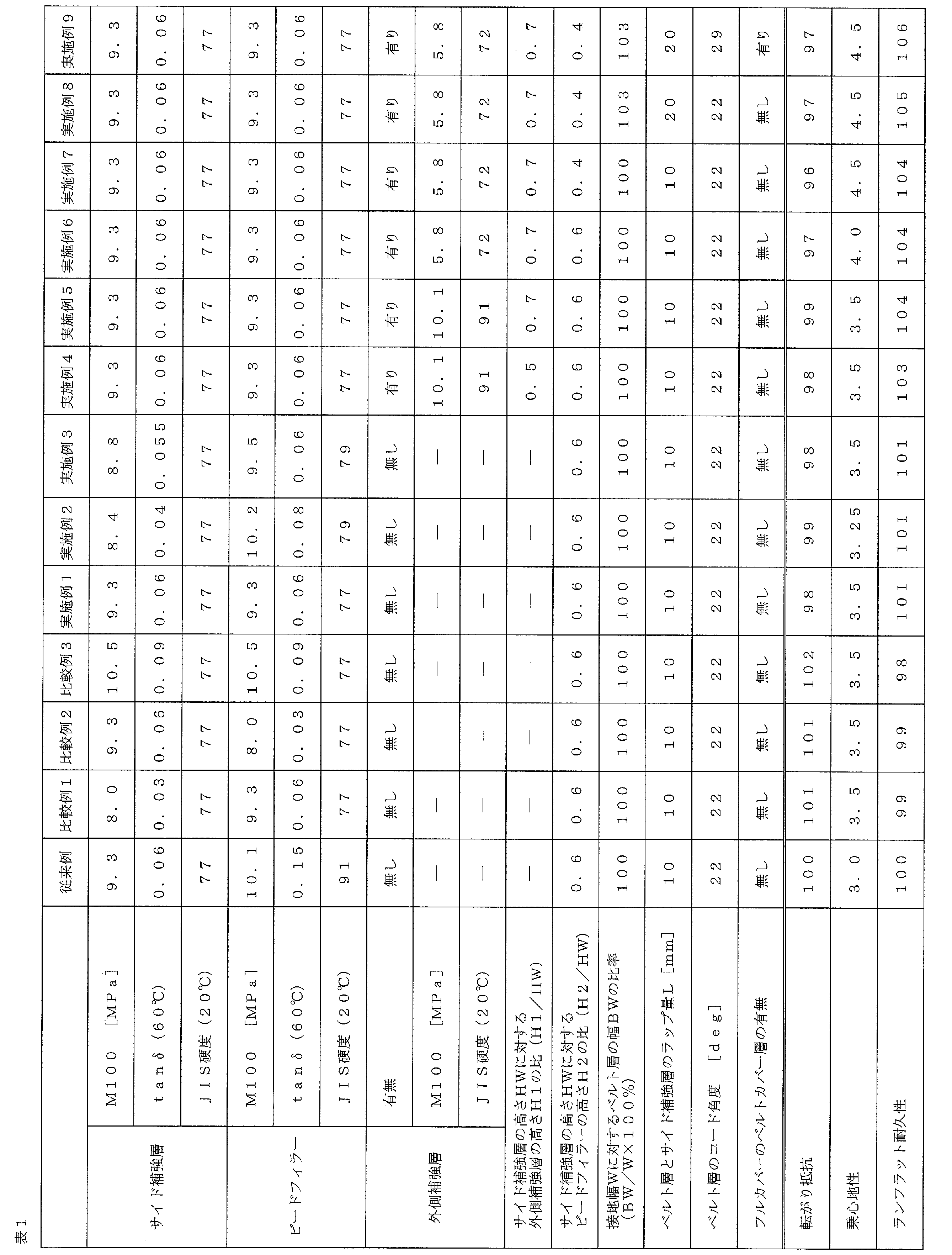
表1から判るように、実施例1~9の空気入りタイヤは、従来例に比して、ランフラット耐久性を改善しながら、転がり抵抗を低減すると共に、乗心地性が改善されていた。
一方、比較例1は、サイド補強層を構成するゴムのM100及びtanδ(60℃)を本発明で規定する範囲外とし、比較例2は、ビードフィラーを構成するゴムのM100及びtanδ(60℃)を本発明で規定する範囲外としたので、転がり抵抗及びランフラット耐久性の改善効果が十分ではなかった。また、比較例3は、サイド補強層とビードフィラーの各々を構成するゴムのM100及びtanδ(60℃)を本発明で規定する範囲外としたので、転がり抵抗及びランフラット耐久性の改善効果が十分ではなかった。
1 トレッド部
2 サイドウォール部
3 ビード部
4 カーカス層
5 ビードコア
6 ビードフィラー
7 インナーライナー層
8 ベルト層
9 ベルトカバー層
10 トレッドゴム層
11 サイド補強層
12 サイドゴム層
13 リムクッションゴム層
14 外側補強層
2 サイドウォール部
3 ビード部
4 カーカス層
5 ビードコア
6 ビードフィラー
7 インナーライナー層
8 ベルト層
9 ベルトカバー層
10 トレッドゴム層
11 サイド補強層
12 サイドゴム層
13 リムクッションゴム層
14 外側補強層
Claims (7)
- タイヤ周方向に延在して環状をなすトレッド部と、該トレッド部の両側に配置された一対のサイドウォール部と、これらサイドウォール部のタイヤ径方向内側に配置された一対のビード部とを備え、これら一対のビード部間に少なくとも1層のカーカス層が装架され、該カーカス層が各ビード部のビードコアの廻りにタイヤ内側から外側へ巻き上げられ、前記ビード部における各ビードコアの外周側にビードフィラーが配置され、前記トレッド部における前記カーカス層の外周側に複数層のベルト層が配置されると共に、前記サイドウォール部における前記カーカス層のタイヤ幅方向内側に断面三日月状のサイド補強層が配置された空気入りタイヤにおいて、
前記サイド補強層を構成するゴムと前記ビードフィラーを構成するゴムの物性として、100%伸長時におけるモジュラスが8.4MPa~10.2MPaの範囲であり、60℃におけるtanδが0.04~0.08の範囲であり、20℃におけるJIS硬度が75~79の範囲であることを特徴とする空気入りタイヤ。 - 前記サイドウォール部における前記カーカス層のタイヤ幅方向外側に前記ビードフィラー及び前記サイド補強層とタイヤ径方向に重なる外側補強層を有することを特徴とする請求項1に記載の空気入りタイヤ。
- 前記ビード部のビードヒールから前記サイド補強層の最大厚さ位置までの高さHWと、前記ビード部のビードヒールから前記外側補強層のタイヤ径方向外側端部までの高さH1とが0.6≦H1/HW≦0.8の関係を満たすことを特徴とする請求項2に記載の空気入りタイヤ。
- 前記外側補強層を構成するゴムの物性として、100%伸長時におけるモジュラスが5.2MPa~6.4MPaの範囲であり、20℃におけるJIS硬度が70~74の範囲であることを特徴とする請求項2又は3に記載の空気入りタイヤ。
- 前記ビード部のビードヒールから前記サイド補強層の最大厚さ位置までの高さHWと、前記ビード部のビードヒールから前記ビードフィラーのタイヤ径方向外側端部までの高さH2とが0.35≦H2/HW≦0.50の関係を満たすことを特徴とする請求項1~4のいずれかに記載の空気入りタイヤ。
- 接地幅に対するタイヤ径方向最外側に位置するベルト層の幅の比率が101%~110%の範囲であり、タイヤ径方向最内側に位置するベルト層と前記サイド補強層とのラップ量が15mm~30mmの範囲であることを特徴とする請求項1~5のいずれかに記載の空気入りタイヤ。
- 前記ベルト層のタイヤ周方向に対するコード角度が25°~35°の範囲であり、前記ベルト層の外周側に全幅を覆う少なくとも1層のベルトカバー層を有することを特徴とする請求項1~6のいずれかに記載の空気入りタイヤ。
Priority Applications (3)
| Application Number | Priority Date | Filing Date | Title |
|---|---|---|---|
| DE112019004697.7T DE112019004697B4 (de) | 2018-10-26 | 2019-10-10 | Luftreifen |
| US17/283,173 US11890898B2 (en) | 2018-10-26 | 2019-10-10 | Pneumatic tire |
| CN201980066248.9A CN112805160B (zh) | 2018-10-26 | 2019-10-10 | 充气轮胎 |
Applications Claiming Priority (2)
| Application Number | Priority Date | Filing Date | Title |
|---|---|---|---|
| JP2018-201625 | 2018-10-26 | ||
| JP2018201625A JP7047703B2 (ja) | 2018-10-26 | 2018-10-26 | 空気入りタイヤ |
Publications (1)
| Publication Number | Publication Date |
|---|---|
| WO2020085100A1 true WO2020085100A1 (ja) | 2020-04-30 |
Family
ID=70331939
Family Applications (1)
| Application Number | Title | Priority Date | Filing Date |
|---|---|---|---|
| PCT/JP2019/039962 Ceased WO2020085100A1 (ja) | 2018-10-26 | 2019-10-10 | 空気入りタイヤ |
Country Status (5)
| Country | Link |
|---|---|
| US (1) | US11890898B2 (ja) |
| JP (1) | JP7047703B2 (ja) |
| CN (1) | CN112805160B (ja) |
| DE (1) | DE112019004697B4 (ja) |
| WO (1) | WO2020085100A1 (ja) |
Families Citing this family (2)
| Publication number | Priority date | Publication date | Assignee | Title |
|---|---|---|---|---|
| US11338622B2 (en) * | 2018-11-16 | 2022-05-24 | The Yokohama Rubber Co., Ltd. | Run-flat tire |
| JP2022157668A (ja) * | 2021-03-31 | 2022-10-14 | 株式会社ブリヂストン | ランフラットタイヤ |
Citations (8)
| Publication number | Priority date | Publication date | Assignee | Title |
|---|---|---|---|---|
| JP2004231922A (ja) * | 2003-02-03 | 2004-08-19 | Bridgestone Corp | タイヤ |
| JP2007069890A (ja) * | 2005-08-08 | 2007-03-22 | Sumitomo Rubber Ind Ltd | ランフラットタイヤ |
| JP2010006327A (ja) * | 2008-06-30 | 2010-01-14 | Bridgestone Corp | 空気入りランフラットタイヤ |
| JP2010155549A (ja) * | 2008-12-26 | 2010-07-15 | Bridgestone Corp | 空気入りタイヤ |
| JP2012096656A (ja) * | 2010-11-02 | 2012-05-24 | Yokohama Rubber Co Ltd:The | 空気入りランフラットタイヤ |
| JP2013095369A (ja) * | 2011-11-04 | 2013-05-20 | Yokohama Rubber Co Ltd:The | 空気入りタイヤ |
| JP2014201230A (ja) * | 2013-04-05 | 2014-10-27 | 横浜ゴム株式会社 | ランフラットタイヤ |
| WO2017188408A1 (ja) * | 2016-04-28 | 2017-11-02 | 株式会社ブリヂストン | ランフラットラジアルタイヤ |
Family Cites Families (17)
| Publication number | Priority date | Publication date | Assignee | Title |
|---|---|---|---|---|
| JPH07304312A (ja) | 1994-05-13 | 1995-11-21 | Bridgestone Corp | 空気入り安全タイヤ |
| WO2002002356A1 (fr) * | 2000-07-03 | 2002-01-10 | Bridgestone Corporation | Pneumatique |
| EP1526154A4 (en) * | 2002-07-31 | 2006-02-22 | Yokohama Rubber Co Ltd | RUBBER COMPOSITION AND PNEUMATIC MATERIAL PRODUCED THEREFROM |
| JP4220201B2 (ja) * | 2002-09-02 | 2009-02-04 | 株式会社ブリヂストン | 安全タイヤ |
| EP1700718A3 (en) * | 2005-03-10 | 2012-05-02 | Sumitomo Rubber Industries, Ltd. | Run-flat tire |
| US7406990B2 (en) * | 2005-08-10 | 2008-08-05 | The Goodyear Tire & Rubber Company | Runflat tire with sidewall component containing high strength glass bubbles |
| JP5262026B2 (ja) | 2007-09-05 | 2013-08-14 | 横浜ゴム株式会社 | ランフラットタイヤとリムとの組立体 |
| US20090294007A1 (en) * | 2008-06-02 | 2009-12-03 | Walter Vorreiter | Performance tire with sidewall insert |
| WO2011129444A1 (ja) * | 2010-04-15 | 2011-10-20 | 株式会社ブリヂストン | 空気入りタイヤ |
| JP5263264B2 (ja) * | 2010-11-02 | 2013-08-14 | 横浜ゴム株式会社 | 空気入りランフラットタイヤ |
| JP5962481B2 (ja) * | 2012-02-08 | 2016-08-03 | 横浜ゴム株式会社 | 空気入りタイヤ |
| JP6028359B2 (ja) * | 2012-03-23 | 2016-11-16 | 横浜ゴム株式会社 | 空気入りタイヤ |
| JP5835171B2 (ja) | 2012-09-14 | 2015-12-24 | 横浜ゴム株式会社 | ランフラットタイヤ |
| CN104936796B (zh) * | 2013-03-15 | 2017-03-29 | 横滨橡胶株式会社 | 零压轮胎 |
| WO2015194469A1 (ja) * | 2014-06-17 | 2015-12-23 | 横浜ゴム株式会社 | 空気入りタイヤ |
| JP6672726B2 (ja) * | 2015-11-11 | 2020-03-25 | 住友ゴム工業株式会社 | ランフラットタイヤ |
| JP6519623B2 (ja) | 2017-10-02 | 2019-05-29 | 横浜ゴム株式会社 | ランフラットタイヤ |
-
2018
- 2018-10-26 JP JP2018201625A patent/JP7047703B2/ja active Active
-
2019
- 2019-10-10 CN CN201980066248.9A patent/CN112805160B/zh active Active
- 2019-10-10 WO PCT/JP2019/039962 patent/WO2020085100A1/ja not_active Ceased
- 2019-10-10 US US17/283,173 patent/US11890898B2/en active Active
- 2019-10-10 DE DE112019004697.7T patent/DE112019004697B4/de active Active
Patent Citations (8)
| Publication number | Priority date | Publication date | Assignee | Title |
|---|---|---|---|---|
| JP2004231922A (ja) * | 2003-02-03 | 2004-08-19 | Bridgestone Corp | タイヤ |
| JP2007069890A (ja) * | 2005-08-08 | 2007-03-22 | Sumitomo Rubber Ind Ltd | ランフラットタイヤ |
| JP2010006327A (ja) * | 2008-06-30 | 2010-01-14 | Bridgestone Corp | 空気入りランフラットタイヤ |
| JP2010155549A (ja) * | 2008-12-26 | 2010-07-15 | Bridgestone Corp | 空気入りタイヤ |
| JP2012096656A (ja) * | 2010-11-02 | 2012-05-24 | Yokohama Rubber Co Ltd:The | 空気入りランフラットタイヤ |
| JP2013095369A (ja) * | 2011-11-04 | 2013-05-20 | Yokohama Rubber Co Ltd:The | 空気入りタイヤ |
| JP2014201230A (ja) * | 2013-04-05 | 2014-10-27 | 横浜ゴム株式会社 | ランフラットタイヤ |
| WO2017188408A1 (ja) * | 2016-04-28 | 2017-11-02 | 株式会社ブリヂストン | ランフラットラジアルタイヤ |
Also Published As
| Publication number | Publication date |
|---|---|
| JP7047703B2 (ja) | 2022-04-05 |
| CN112805160B (zh) | 2023-03-31 |
| DE112019004697T5 (de) | 2021-06-10 |
| JP2020066387A (ja) | 2020-04-30 |
| US11890898B2 (en) | 2024-02-06 |
| US20210339582A1 (en) | 2021-11-04 |
| DE112019004697B4 (de) | 2026-03-05 |
| CN112805160A (zh) | 2021-05-14 |
Similar Documents
| Publication | Publication Date | Title |
|---|---|---|
| JP6859825B2 (ja) | 空気入りタイヤ | |
| CN111094021B (zh) | 泄气保用轮胎 | |
| JP5732817B2 (ja) | 空気入りランフラットタイヤ | |
| JP6844718B2 (ja) | ランフラットタイヤ | |
| JP5298668B2 (ja) | 空気入りタイヤ | |
| JP2012071709A (ja) | ランフラットタイヤ | |
| JP5251178B2 (ja) | 空気入りタイヤ | |
| JP5277892B2 (ja) | 空気入りタイヤ | |
| JP7047703B2 (ja) | 空気入りタイヤ | |
| CN108116168A (zh) | 充气轮胎 | |
| JP7311779B2 (ja) | ランフラットタイヤ | |
| JP4586344B2 (ja) | 空気入りタイヤ | |
| JP5251179B2 (ja) | 空気入りタイヤ | |
| JP4765483B2 (ja) | 空気入りタイヤ | |
| JP4525352B2 (ja) | 空気入りタイヤ | |
| JP7626942B2 (ja) | タイヤ | |
| JP6455095B2 (ja) | 空気入りタイヤ | |
| JP6450111B2 (ja) | 空気入りタイヤ | |
| JP4935521B2 (ja) | 空気入りタイヤ | |
| WO2023002702A1 (ja) | タイヤ | |
| WO2023002701A1 (ja) | タイヤ | |
| JP2005297873A (ja) | 重荷重用空気入りラジアルタイヤ | |
| JP2021185055A (ja) | 空気入りタイヤ | |
| JP2020152165A (ja) | 空気入りタイヤ | |
| JP2006176012A (ja) | 空気入りラジアルタイヤ |
Legal Events
| Date | Code | Title | Description |
|---|---|---|---|
| 121 | Ep: the epo has been informed by wipo that ep was designated in this application |
Ref document number: 19876343 Country of ref document: EP Kind code of ref document: A1 |
|
| WWE | Wipo information: entry into national phase |
Ref document number: 112019004697 Country of ref document: DE |
|
| 122 | Ep: pct application non-entry in european phase |
Ref document number: 19876343 Country of ref document: EP Kind code of ref document: A1 |
|
| WWG | Wipo information: grant in national office |
Ref document number: 112019004697 Country of ref document: DE |