WO2020054631A1 - 工具 - Google Patents
工具 Download PDFInfo
- Publication number
- WO2020054631A1 WO2020054631A1 PCT/JP2019/035259 JP2019035259W WO2020054631A1 WO 2020054631 A1 WO2020054631 A1 WO 2020054631A1 JP 2019035259 W JP2019035259 W JP 2019035259W WO 2020054631 A1 WO2020054631 A1 WO 2020054631A1
- Authority
- WO
- WIPO (PCT)
- Prior art keywords
- housing
- sensor
- link member
- cover
- tool
- Prior art date
- Legal status (The legal status is an assumption and is not a legal conclusion. Google has not performed a legal analysis and makes no representation as to the accuracy of the status listed.)
- Ceased
Links
Images









Classifications
-
- B—PERFORMING OPERATIONS; TRANSPORTING
- B24—GRINDING; POLISHING
- B24B—MACHINES, DEVICES, OR PROCESSES FOR GRINDING OR POLISHING; DRESSING OR CONDITIONING OF ABRADING SURFACES; FEEDING OF GRINDING, POLISHING, OR LAPPING AGENTS
- B24B23/00—Portable grinding machines, e.g. hand-guided; Accessories therefor
- B24B23/005—Auxiliary devices used in connection with portable grinding machines, e.g. holders
-
- B—PERFORMING OPERATIONS; TRANSPORTING
- B24—GRINDING; POLISHING
- B24B—MACHINES, DEVICES, OR PROCESSES FOR GRINDING OR POLISHING; DRESSING OR CONDITIONING OF ABRADING SURFACES; FEEDING OF GRINDING, POLISHING, OR LAPPING AGENTS
- B24B23/00—Portable grinding machines, e.g. hand-guided; Accessories therefor
- B24B23/02—Portable grinding machines, e.g. hand-guided; Accessories therefor with rotating grinding tools; Accessories therefor
-
- B—PERFORMING OPERATIONS; TRANSPORTING
- B24—GRINDING; POLISHING
- B24B—MACHINES, DEVICES, OR PROCESSES FOR GRINDING OR POLISHING; DRESSING OR CONDITIONING OF ABRADING SURFACES; FEEDING OF GRINDING, POLISHING, OR LAPPING AGENTS
- B24B49/00—Measuring or gauging equipment for controlling the feed movement of the grinding tool or work; Arrangements of indicating or measuring equipment, e.g. for indicating the start of the grinding operation
-
- B—PERFORMING OPERATIONS; TRANSPORTING
- B24—GRINDING; POLISHING
- B24B—MACHINES, DEVICES, OR PROCESSES FOR GRINDING OR POLISHING; DRESSING OR CONDITIONING OF ABRADING SURFACES; FEEDING OF GRINDING, POLISHING, OR LAPPING AGENTS
- B24B55/00—Safety devices for grinding or polishing machines; Accessories fitted to grinding or polishing machines for keeping tools or parts of the machine in good working condition
- B24B55/04—Protective covers for the grinding wheel
- B24B55/05—Protective covers for the grinding wheel specially designed for portable grinding machines
- B24B55/052—Protective covers for the grinding wheel specially designed for portable grinding machines with rotating tools
-
- B—PERFORMING OPERATIONS; TRANSPORTING
- B25—HAND TOOLS; PORTABLE POWER-DRIVEN TOOLS; MANIPULATORS
- B25F—COMBINATION OR MULTI-PURPOSE TOOLS NOT OTHERWISE PROVIDED FOR; DETAILS OR COMPONENTS OF PORTABLE POWER-DRIVEN TOOLS NOT PARTICULARLY RELATED TO THE OPERATIONS PERFORMED AND NOT OTHERWISE PROVIDED FOR
- B25F5/00—Details or components of portable power-driven tools not particularly related to the operations performed and not otherwise provided for
-
- B—PERFORMING OPERATIONS; TRANSPORTING
- B25—HAND TOOLS; PORTABLE POWER-DRIVEN TOOLS; MANIPULATORS
- B25F—COMBINATION OR MULTI-PURPOSE TOOLS NOT OTHERWISE PROVIDED FOR; DETAILS OR COMPONENTS OF PORTABLE POWER-DRIVEN TOOLS NOT PARTICULARLY RELATED TO THE OPERATIONS PERFORMED AND NOT OTHERWISE PROVIDED FOR
- B25F5/00—Details or components of portable power-driven tools not particularly related to the operations performed and not otherwise provided for
- B25F5/02—Construction of casings, bodies or handles
Definitions
- WO 2017/051893 discloses a motor, a power transmission mechanism connected to the motor, a housing accommodating the motor and the power transmission mechanism, and a tip tool connected to the power transmission mechanism.
- a tool including a tip tool holding portion for holding, an accessory detachably attached to the housing, and a detection sensor provided outside the housing is disclosed. In this tool, the detection sensor can detect whether or not an accessory is attached to the housing.
- the above tools may be used in an environment where the air contains a lot of dust.
- the detection sensor if the detection sensor is provided outside the housing, the detection sensor may erroneously detect due to the influence of dust. Even when a tool is used in a dusty environment, a technique that can accurately detect whether an accessory is attached to a housing is expected.
- the tool includes a prime mover, a power transmission mechanism connected to the prime mover, a housing accommodating the prime mover and the power transmission mechanism, and a tip tool holding part connected to the power transmission mechanism and holding a tip tool.
- an accessory detachably attached to the housing, a link member that operates in accordance with the attachment and detachment of the accessory, and a detection sensor housed inside the housing and including a non-contact sensor element. May be.
- the detection sensor may detect an operation of the link member using the sensor element.
- the detection sensor since the detection sensor is housed inside the housing, the detection sensor is not easily affected by dust. Therefore, even when the tool is used in a dusty environment, it is possible to accurately detect whether the accessory is attached to the housing. According to the above configuration, the detection sensor detects the operation of the link member using the non-contact sensor element. Thereby, even when vibration or impact acts on the link member, it is possible to prevent impact or vibration acting on the sensor element via the link member. It is possible to prevent erroneous detection by the sensor element due to shock or vibration, and to improve the durability of the sensor element.
- the tool includes a prime mover, a power transmission mechanism connected to the prime mover, a housing accommodating the prime mover and the power transmission mechanism, and a tip tool holding part connected to the power transmission mechanism and holding a tip tool.
- an accessory detachably attached to the housing, a link member that operates according to the attachment and detachment of the accessory, and a detection sensor housed inside the housing.
- the link member may rotate with respect to the housing according to attachment / detachment of the accessory.
- the detection sensor may detect a rotation operation of the link member.
- the detection sensor since the detection sensor is housed inside the housing, the detection sensor is not easily affected by dust. Therefore, even when the tool is used in a dusty environment, it is possible to accurately detect whether the accessory is attached to the housing. Further, according to the above configuration, even when the detection sensor is arranged at a position distant from the attachment position of the accessory, the link member does not need to be a large and complicated mechanism, and the inside of the housing is not required. By utilizing the vacant space, a link member extending from the attachment position of the accessory to the position of the detection sensor can be arranged.
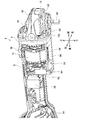
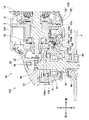
- FIG. 2 is a vertical sectional view of the grinder 2 according to the first embodiment.
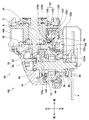
- FIG. 2 is a perspective view illustrating an internal structure of the grinder 2 according to the first embodiment.
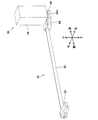
- FIG. 5 is a perspective view of the cover detection mechanism 54 in a state where the cover 6 is not attached to the grinder 2 of the first embodiment.
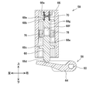
- FIG. 3 is a perspective view illustrating an internal structure of a detection sensor 58 of the grinder 2 according to the first embodiment.
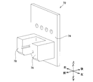
- FIG. 3 is a perspective view of a photo interrupter 72 of the grinder 2 according to the first embodiment.
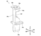
- FIG. 3 is a perspective view of a sensor lever 68 of the grinder 2 according to the first embodiment.
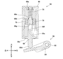
- FIG. 3 is a vertical cross-sectional view of the detection sensor 58 in a state where the cover 6 is not attached to the grinder 2 of the first embodiment.
- FIG. 3 is a perspective view of the cover detection mechanism 54 in a state where the cover 6 is attached to the grinder 2 of the first embodiment.
- FIG. 4 is a vertical cross-sectional view of the detection sensor 58 in a state where the cover 6 is attached to the grinder 2 of the first embodiment.
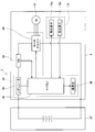
- FIG. 2 is a diagram schematically illustrating a circuit configuration of the grinder 2 according to the first embodiment.
- 5 is a flowchart illustrating a process executed by the microcomputer 82 of the grinder 2 according to the first embodiment.
- 5 is a flowchart illustrating a cover determination process executed by the microcomputer 82 of the grinder 2 according to the first embodiment.
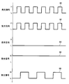
- FIG. 3 is a diagram illustrating an example of a signal pattern 90 of a light emission signal and signal patterns 92, 94, 96, and 98 of a light reception signal in the grinder 2 according to the first embodiment.
- FIG. 9 is a perspective view of a grinder 102 according to a second embodiment.
- FIG. 10 is a vertical cross-sectional view of the vicinity of a cover attachment portion 52 in a state where a cover 6 is not attached to the grinder 102 according to the second embodiment.
- FIG. 10 is a cross-sectional view of the vicinity of handle attachment portions 110 and 112 in a state where a side handle 108 is not attached to the grinder 102 according to the second embodiment.
- FIG. 10 is a perspective view of a detection unit 118 of the grinder 102 according to the second embodiment.
- FIG. 10 is a perspective view of the link member 122 and the photointerrupter 128 in a state where the link member 122 is in a shielding position in the grinder 102 according to the second embodiment.
- FIG. 10 is a perspective view of the link member 122 and the photointerrupter 128 in a state where the link member 122 is in an open position in the grinder 102 according to the second embodiment.
- FIG. 10 is a vertical cross-sectional view of the vicinity of a cover attachment portion 52 in a state where a cover 6 is attached to the grinder 102 according to the second embodiment.
- FIG. 10 is a cross-sectional view of the vicinity of handle mounting portions 110 and 112 in a state where a side handle 108 is mounted in the grinder 102 according to the second embodiment.
- a tool is connected to the prime mover, a power transmission mechanism connected to the prime mover, a housing containing the prime mover and the power transmission mechanism, and the power transmission mechanism.
- a tip tool holding portion for holding a tip tool, an accessory detachably attached to the housing, a link member that operates according to the attachment / detachment of the accessory, and a non-contact type accommodated in the housing. May be provided.
- the detection sensor may detect an operation of the link member using the sensor element.
- the detection sensor since the detection sensor is housed inside the housing, the detection sensor is not easily affected by dust. Therefore, even when the tool is used in a dusty environment, it is possible to accurately detect whether the accessory is attached to the housing. According to the above configuration, the detection sensor detects the operation of the link member using the non-contact sensor element. Thereby, even when vibration or impact acts on the link member, it is possible to prevent impact or vibration acting on the sensor element via the link member. It is possible to prevent erroneous detection by the sensor element due to shock or vibration, and to improve the durability of the sensor element.
- the tool may further include a control unit that controls operation of the prime mover.
- the control unit may permit driving of the prime mover based on a detection signal from the detection sensor.
- the drive of the prime mover can be permitted only when the accessory is attached to the housing.
- the link member may extend from inside to outside of the housing.
- the detection sensor includes a sensor case housing the sensor element, and a sensor extending from inside to outside of the sensor case, the sensor being operated in response to an operation of the link member.
- a lever may be further provided.
- the sensor element may detect an operation of the sensor lever.
- the sensor element of the detection sensor is housed inside the sensor case, even if dust flows into the housing, it is possible to prevent the sensor element from being affected by the dust. it can.
- the sensor element may include a light emitting element and a light receiving element that receives light from the light emitting element.
- the sensor lever may be movable between a first position that does not block between the light emitting element and the light receiving element and a second position that blocks between the light emitting element and the light receiving element.
- the sensor lever may be located at one of the first position and the second position when the accessory is not attached to the housing.
- the sensor lever may be located at the other of the first position and the second position when the accessory is attached to the housing.
- a sensor element having a light-emitting element and a light-receiving element as described above is less susceptible to an external environment such as metal powder than a sensor element having a magnet and a Hall element. According to the above configuration, the position of the sensor lever is switched between the first position and the second position in accordance with attachment / detachment of the accessory. It can be determined whether an article is attached.
- the light emitting device may emit light based on a light emitting signal having a predetermined signal pattern.
- the accessory is attached to the housing simply by the presence or absence of light transmission from the light emitting element to the light receiving element. If an attempt is made to determine whether or not an accessory has been attached to the housing, an ON failure or an OFF failure may occur in the light receiving element.
- the light receiving signal at the light receiving element is the same as the light emitting signal at the light emitting element Will have a pattern. For this reason, by comparing the signal pattern of the light receiving signal in the light receiving element and the signal pattern of the light emitting signal in the light emitting element, it is determined whether or not an accessory is attached to the housing. Erroneous determination can be prevented.
- the sensor lever may be formed to be slidable on an inner side surface of the sensor case.
- the sensor lever has a substantially flat base having a longitudinal direction in the vertical direction and a short direction in the front-rear direction, and a contact portion protruding from the sensor case and contacting the link member. Is also good.
- a cutout portion having a shape that does not block between the light emitting element and the light receiving element and a shielding portion having a shape that blocks between the light emitting element and the light receiving element may be formed in the base portion.
- the accessory may include a cover that at least partially covers the accessory tool.
- the housing may include a cover attaching portion to which the cover is attached.
- the link member may include a round bar-shaped shaft, a front lever fixed to a front end of the shaft, and a rear lever fixed to a rear end of the shaft.
- the front end of the shaft may protrude outside the housing via a through hole formed in the housing.
- the front lever may be arranged outside the housing and near the cover mounting portion.
- the rear lever may be disposed inside the housing and below the detection sensor.
- the front lever when the cover is attached to the cover attaching portion, the front lever is pressed by the cover and pivots upward, and the rear lever also moves upward.
- the notch is arranged between the light emitting element and the light receiving element, by rotating toward the, the contact portion is pressed by the rear lever and the sensor lever moves upward, The light from the light emitting element may reach the light receiving element without being interrupted.
- the attachment / detachment of the cover to / from the housing can be detected by the detection sensor with a simple configuration.
- the link member may be rotatably supported with respect to the housing.
- the link member may rotate with respect to the housing according to attachment / detachment of the accessory.
- the link member does not need to be a large and complicated mechanism, and the inside of the housing becomes empty.
- the link member extending from the attachment position of the accessory to the position of the detection sensor can be arranged by utilizing the space.
- the prime mover may be an electric motor.
- a longitudinal direction of the link member may be arranged along a first direction substantially parallel to an output shaft of the electric motor housed inside the housing.
- the rotation axis of the link member may be arranged along the first direction.
- the sensor lever may be held by the sensor case so as to be movable in a second direction substantially orthogonal to the first direction.
- the detection sensor may be housed inside the sensor case, and may further include an elastic member for urging the sensor lever from the first position to the second position.
- the configurations of the link member and the detection sensor can be simplified.
- the tool may further include a control unit that controls electric power supplied to the electric motor.
- the detection sensor may be arranged between the electric motor and the control unit.
- the detection sensor can be arranged by utilizing an empty space inside the housing between the electric motor and the control unit.
- the tool may further include a battery removably mounted on the housing and supplying power to the electric motor, wherein the detection sensor includes the electric motor and the electric motor. It may be arranged between the batteries.
- the detection sensor can be arranged by utilizing an empty space between the electric motor and the battery inside the housing.
- the accessory may be a cover that at least partially covers the accessory tool.
- the detection sensor can detect whether or not the cover that at least partially covers the tip tool is attached to the housing.
- the detection sensor may further include a sensor case that houses the sensor element.
- the link member may extend from the inside to the outside of the sensor case.
- the sensor element may detect an operation of the link member.
- the configuration of the detection sensor can be simplified, and the number of components can be reduced. Can be.
- the sensor element may include a light emitting element and a light receiving element that receives light from the light emitting element.
- the link member may be movable between a first position that does not block between the light emitting element and the light receiving element and a second position that blocks between the light emitting element and the light receiving element.
- the link member may be located at one of the first position and the second position when the accessory is not attached to the housing.
- the link member may be located at the other of the first position and the second position when the accessory is attached to the housing.
- the light emitting device may emit light based on a light emitting signal having a predetermined signal pattern.
- the link member includes a swing shaft that is swingably held by the sensor case, a contact arm protruding outside the sensor case, and an inside of the sensor case. It may include a detection arm housed therein.
- the contact arm may include a flange and a protruding portion protruding from the flange.
- the detection arm may include a shielding part having a shape that shields between the light emitting element and the light receiving element.
- the accessory may include a cover that at least partially covers the accessory tool.
- the housing may include a cover attaching portion to which the cover is attached.
- the sensor case may be arranged inside the housing near a central portion in the left-right direction of the housing.
- the sensor case may be held by the housing such that the swing shaft is arranged along the left-right direction and the projecting portion faces downward.
- the contact arm may project outside the housing via a through hole in the housing.
- the flange and the protruding portion may be disposed outside the housing and near the cover attaching portion.
- the attachment / detachment of the cover to / from the housing can be detected by the detection sensor with a simple configuration.
- the accessory may include a handle that can be gripped by a user.
- the housing may include a handle mounting hole to which the handle is mounted.
- the sensor case may be arranged inside the housing.
- the sensor case may be held by the housing such that the swing shaft is arranged along a vertical direction, and the projecting portion faces the handle mounting hole.
- the flange When the handle is not attached to the handle mounting hole, the flange may be in contact with an inner surface of the housing, and the protrusion may enter the handle mounting hole.
- the attachment / detachment of the handle to / from the housing can be detected by the detection sensor with a simple configuration.
- the link member may be rotatably supported with respect to the sensor case.
- the link member may rotate with respect to the sensor case according to attachment / detachment of the accessory.
- the prime mover may be an electric motor.
- the rotation axis of the link member and the sensor element may be arranged side by side in a direction substantially orthogonal to an output shaft of the electric motor housed in the housing.
- the rotation axis of the link member is disposed along a second direction substantially orthogonal to a first direction substantially parallel to the output shaft of the electric motor. May be.
- the tool may further include an elastic member for urging the link member from the first position toward the second position.
- the configurations of the link member and the detection sensor can be further simplified.
- the detection sensor may be disposed between the tip tool holder and the electric motor in a direction in which an output shaft of the electric motor extends.
- the detection sensor can be arranged by utilizing an empty space inside the housing between the tool holding portion and the electric motor.
- the tool may include a plurality of the detection sensors and a plurality of the link members corresponding to the plurality of the detection sensors.
- the accessory may include a cover that at least partially covers the tool bit and / or a handle that can be gripped by a user.
- the detection sensor can detect whether or not the cover that at least partially covers the accessory tool and the handle that can be gripped by the user are attached to the housing.
- a tool is connected to the prime mover, a power transmission mechanism connected to the prime mover, a housing containing the prime mover and the power transmission mechanism, and the power transmission mechanism.
- a tip tool holding portion for holding a tip tool, an accessory detachably attached to the housing, a link member that operates according to attachment / detachment of the accessory, and a detection sensor housed inside the housing. You may.
- the link member may rotate with respect to the housing according to attachment / detachment of the accessory.
- the detection sensor may detect a rotation operation of the link member.
- the detection sensor since the detection sensor is housed inside the housing, the detection sensor is not easily affected by dust. Therefore, even when the tool is used in a dusty environment, it is possible to accurately detect whether the accessory is attached to the housing. Further, according to the above configuration, even when the detection sensor is arranged at a position distant from the attachment position of the accessory, the link member does not need to be a large and complicated mechanism, and the inside of the housing is not required. By utilizing the vacant space, a link member extending from the attachment position of the accessory to the position of the detection sensor can be arranged.
- the tool may further include a control unit that controls operation of the prime mover.
- the control unit may permit driving of the prime mover based on a detection signal from the detection sensor.
- the drive of the prime mover can be permitted only when the accessory is attached to the housing.
- the link member may be rotatably supported with respect to the housing.
- the link member may extend from the inside to the outside of the housing.
- the grinder 2 of this embodiment is a tool used in a state where a grinding wheel 4 as a tip tool and a cover 6 as an accessory are attached.
- the grinder 2 can grind or deburr a metal weld or the like by rotating the grinding wheel 4. Further, by replacing the grinding wheel 4 with one corresponding to the material and work content of the work and replacing the cover 6 with one corresponding to the replaced grinding wheel 4, the work of concrete, block, brick, stone, etc. can be performed. Cutting or the like can be performed.
- the longitudinal direction of the grinder 2 is referred to as the front-rear direction
- the rotation axis direction of the grinding wheel 4 is referred to as the up-down direction
- the direction orthogonal to the front-rear direction is referred to as the left-right direction.
- the grinder 2 includes a main body housing 8, a gear housing cover 9, a gear housing 10, and a bearing box 12.
- An electric motor 14 as a prime mover is accommodated in the front inside of the main body housing 8.
- the electric motor 14 is, for example, an inner rotor type brushless DC motor.
- the electric motor 14 has an output shaft 16 extending in the front-rear direction.
- the output shaft 16 is rotatably supported by the gear housing cover 9 via a bearing 18 and rotatably supported by the main body housing 8 via a bearing 20.
- a battery 22 is attached to a rear end of the main body housing 8.
- the battery 22 is a rechargeable secondary battery such as a lithium ion battery.
- the battery 22 is a slide-type battery that is detachable by sliding the battery 22 up and down with respect to the main body housing 8.
- a control board 24 is accommodated in the rear inside of the main body housing 8.
- Electric power supplied from the battery 22 is supplied to the electric motor 14 via the control board 24.
- a slide switch 26 slidable in the front-rear direction is provided on a front upper surface of the main body housing 8.
- the slide switch 26 can be switched between an on position and an off position by a user operation.
- the position of the slide switch 26 is detected by a main switch 28 housed inside the main body housing 8.
- the main switch 28 is connected to the control board 24.
- the slide switch 26 When the slide switch 26 is in the ON position, electric power from the battery 22 is supplied to the electric motor 14 via the control board 24, and the electric motor 14 rotates the output shaft 16.
- the slide switch 26 is in the off position, the supply of the electric power of the battery 22 to the electric motor 14 is cut off, and the electric motor 14 stops the output shaft 16.
- a display unit 30 is provided on the rear upper surface of the main housing 8.
- the display unit 30 notifies the user of the operating state of the grinder 2 and the remaining battery level of the battery 22 by changing the display according to the operating state of the grinder 2 and the remaining battery level of the battery 22.
- the gear housing 10 is attached to the front of the main body housing 8 via the gear housing cover 9. Inside the gear housing 10, a first bevel gear 32 and a second bevel gear 34 arranged to mesh with each other are housed.
- the first bevel gear 32 is fixed to a front end of the output shaft 16.
- the second bevel gear 34 is fixed to an upper end of a spindle 36 extending in the vertical direction.
- the first bevel gear 32 and the second bevel gear 34 are collectively referred to simply as a bevel gear 38.
- the bevel gear 38 is a reduction mechanism that reduces the rotation of the electric motor 14 and transmits the rotation to the spindle 36, and can be called a power transmission mechanism.
- the gear housing 10 rotatably supports the upper end of the spindle 36 via a bearing 40. As shown in FIG. 2, a shaft lock 42 is provided on the upper surface of the gear housing 10. When the user pushes the shaft lock 42 downward, the rotation of the second bevel gear 34 is prohibited, and the rotation of the spindle 36 is prohibited.
- the bearing box 12 is attached below the gear housing 10.
- the bearing box 12 rotatably supports the spindle 36 via a bearing 44.
- the spindle 36 is rotatable with respect to the bearing box 12 about a rotation axis along the vertical direction.
- the grinding wheel 4 can be attached to the lower end of the spindle 36 via an inner flange 46 and an outer flange 48.
- the inner flange 46 is fitted on the spindle 36.
- the grinding wheel 4 is attached to the spindle 36 from below the inner flange 46 and fitted to the inner flange 46.
- the outer flange 48 is screwed to the spindle 36 from the lower end of the spindle 36, and holds the grinding wheel 4 between the outer flange 48 and the inner flange 46.
- the spindle 36 can also be said to be a tip tool holding unit that holds the grinding wheel 4 as a tip tool.
- the main body housing 8, the gear housing cover 9, the gear housing 10, and the bearing box 12 are collectively referred to simply as a housing 50.
- the cover 6 is attached to a substantially cylindrical cover attaching portion 52 formed on the bearing box 12.
- the cover 6 is formed so as to at least partially cover the grinding wheel 4 when attached to the grinder 2. It can also be said that the cover 6 has a shape that at least partially covers the spindle 36 when attached to the grinder 2. The cover 6 prevents the cutting powder from scattering toward the user when the grinding wheel 4 grinds the work.
- the grinder 2 includes a cover detection mechanism 54.
- the cover detection mechanism 54 includes a link member 56 and a detection sensor 58.
- the detection sensor 58 is housed inside the main body housing 8.
- the detection sensor 58 is disposed between the electric motor 14 and the control board 24.
- the detection sensor 58 is arranged at a position behind the electric motor 14 and ahead of the battery 22 and the control board 24.
- the link member 56 includes a round bar-shaped shaft 60, a front lever 62 fixed to the front end of the shaft 60, and a rear lever 64 fixed to the rear end of the shaft 60.
- the shaft 60 is disposed in the front lower right of the inside of the main body housing 8 so that the longitudinal direction is along the front-rear direction of the grinder 2.
- the shaft 60 is rotatably supported by the main body housing 8.
- the front end of the shaft 60 projects outside the housing 50 through a through hole 10a formed in the gear housing 10, and the front lever 62 is arranged outside the housing 50.
- the front lever 62 is arranged near the cover mounting portion 52 of the bearing box 12.
- the rear lever 64 is arranged below the detection sensor 58 inside the main body housing 8.
- the front lever 62 pivots upward when the cover 6 is attached to the cover attaching portion 52.
- the shaft 60 and the rear lever 64 also rotate integrally.
- the detection sensor 58 has a substantially rectangular parallelepiped shape, a sensor case 66 having an opening on the lower surface, and a part protruding downward from the opening on the lower surface of the sensor case 66.
- a sensor lever 68, a compression spring 70 housed in the sensor case 66, and a photo interrupter 72 housed in the sensor case 66 are provided.
- a rubber seal is provided at an opening on the lower surface of the sensor case 66 so as to be in contact with the periphery of the sensor lever 68 so that the sensor lever 68 can slide. Thus, it is possible to prevent dust from flowing into the sensor case 66.
- the photo interrupter 72 includes a sensor substrate 74, and a light emitting unit 76 and a light receiving unit 78 mounted on the sensor substrate 74.
- the sensor board 74 is fixed to a rear side surface inside the sensor case 66.
- the sensor board 74 is connected to the control board 24 via wiring (not shown).
- the light emitting section 76 and the light receiving section 78 are arranged on the front surface of the sensor board 74.
- the light emitting section 76 and the light receiving section 78 are arranged to face each other in the left-right direction.
- the light emitting section 76 has a built-in light emitting element 76a (see FIG. 10), and the light receiving section 78 has a light receiving element 78a (see FIG. 10).
- the sensor lever 68 has a substantially flat base 68a having a longitudinal direction in the up-down direction and a short direction in the front-rear direction, and an upper guide portion 68b provided at an upper end of the base 68a. , A lower guide portion 68c provided below the vertical center of the base portion 68a.
- the upper guide portion 68b and the lower guide portion 68c are formed in a shape slidable with respect to the inner side surface of the sensor case 66.
- a rounded contact portion 68d is formed at the lower end of the base 68a.
- a spring receiving portion 68e is formed on the upper surface of the upper guide portion 68b.
- a cut-out portion 68f is formed behind a position above the center of the base 68a in the vertical direction.
- the base 68a above the notch 68f constitutes a shielding part 68g.
- the compression spring 70 is disposed above the sensor lever 68 inside the sensor case 66. As shown in FIG. 7, the upper end of the compression spring 70 is in contact with a spring receiving portion 66a formed on the inner top surface of the sensor case 66, and the lower end of the compression spring 70 is in contact with the spring receiving portion 68e of the sensor lever 68. Is in contact with The compression spring 70 urges the sensor lever 68 downward with respect to the sensor case 66. The sensor lever 68 can move downward to a lower limit position where the lower surface of the upper guide portion 68b contacts the upper surfaces of the light emitting portion 76 and the light receiving portion 78 of the photo interrupter 72.
- the shielding part 68g of the base 68a is arranged between the light emitting part 76 and the light receiving part 78. In this state, the light from the light emitting unit 76 is blocked by the blocking unit 68g and does not reach the light receiving unit 78.
- the rear lever 64 of the link member 56 is located below the contact portion 68d of the detection sensor 58.
- the cover 6 is not attached to the grinder 2 and no external force acts on the front lever 62, no upward force acts on the contact portion 68d from the rear lever 64, so that the sensor lever 68 is maintained at the lower limit position. Is done.
- the front lever 62 When the cover 6 is attached to the grinder 2, the front lever 62 is pushed up by the cover 6, and as shown in FIG. 8, the front lever 62 rotates upward. As a result, the rear lever 64 also rotates upward, and the contact portion 68d of the sensor lever 68 is pushed up by the rear lever 64. As shown in FIG. 9, when the sensor lever 68 is pushed up, the cutout 68 f of the base 68 a is arranged between the light emitting unit 76 and the light receiving unit 78. In this state, light from the light emitting section 76 reaches the light receiving section 78 without being blocked. The position of the sensor lever 68 in this state is also referred to as an upper limit position.
- FIG. 10 shows the circuit configuration of the grinder 2.
- a regulator 80 adjusts the power supplied from battery 22 to a predetermined voltage.
- the motor driver 84 includes a plurality of switching elements (not shown) controlled by the microcomputer 82, and controls electric power supplied to the electric motor 14.
- the indicator light 86 includes a plurality of light emitting elements (not shown), and switches the content displayed on the display unit 30.
- the microcomputer 82 receives a signal indicating an on / off state from the main switch 28.
- the microcomputer 82 transmits a light emission signal to the light emitting element 76 a of the photo interrupter 72 and receives a light reception signal from the light receiving element 78 a of the photo interrupter 72.
- FIG. 11 is a flowchart showing a process performed by the microcomputer 82.
- step S2 the microcomputer 82 waits until the main switch 28 is turned on. When the main switch 28 is turned on, the process proceeds to step S4.
- step S4 the microcomputer 82 performs a cover determination process shown in FIG.
- step S32 the microcomputer 82 transmits a light emission signal to the light emitting element 76a of the photo interrupter 72.
- the microcomputer 82 transmits a signal pattern 90 (see FIG. 13) having a pulse train that switches between the H potential and the L potential at a predetermined cycle as a light emission signal.
- step S34 the microcomputer 82 receives a light receiving signal from the light receiving element 78a of the photo interrupter 72.
- step S36 the microcomputer 82 determines whether or not the cycle of the light emission signal transmitted in step S32 and the cycle of the light reception signal received in step S34 match.
- the signal pattern 90 of the light emitting signal is used as the light receiving signal.
- a signal pattern 92 having a pulse train of the same period is received.
- a signal pattern 94 having a constant L potential is used as a light-receiving signal. Is received.
- step S36 of FIG. 12 when the periods of the light emission signal and the light reception signal match (in the case of YES), the microcomputer 82 determines that the cover 6 is attached to the cover attachment portion 52, and the process proceeds to step S38. move on.
- step S38 the microcomputer 82 permits the driving of the electric motor 14. After step S38, the cover determination process shown in FIG. 12 ends.
- step S36 in FIG. 12 when the periods of the light emission signal and the light reception signal do not match (in the case of NO), the microcomputer 82 determines whether the cover 6 is not attached to the cover attachment portion 52 or an abnormality has occurred in the photo interrupter 72. The process proceeds to step S40. In step S40, the microcomputer 82 prohibits the driving of the electric motor 14. After step S40, the cover determination process shown in FIG. 12 ends.
- step S6 the microcomputer 82 determines whether the driving of the electric motor 14 is permitted. If the driving of the electric motor 14 is prohibited (NO), the process proceeds to step S8.
- step S8 the microcomputer 82 controls the display lamp 86 to display a warning on the display unit 30.
- step S10 the microcomputer 82 waits until the main switch 28 is turned off.
- the process proceeds to step S12.
- step S12 the microcomputer 82 controls the display lamp 86 to cancel the warning display on the display unit 30. After step S12, the process returns to step S2.
- step S6 If the driving of the electric motor 14 is permitted in step S6 (YES), the process proceeds to step S14.
- the microcomputer 82 controls the motor driver 84 to start driving the electric motor 14. Thereby, the grinding wheel 4 rotates, and the workpiece can be ground using the grinder 2.
- step S16 the microcomputer 82 performs the cover determination process shown in FIG. 12 again.
- the cover determination process when the cover 6 is directly attached to the cover attaching portion 52, the driving of the electric motor 14 is permitted (step S38 in FIG. 12), and the cover 6 is removed from the cover attaching portion 52. In this case, the driving of the electric motor 14 is prohibited (step S40 in FIG. 12).
- step S18 the microcomputer 82 determines whether the driving of the electric motor 14 is permitted. If the driving of the electric motor 14 is prohibited (NO), the process proceeds to step S20.
- step S20 the microcomputer 82 controls the motor driver 84 to stop driving the electric motor 14.
- step S22 the microcomputer 82 controls the display lamp 86 to display a warning on the display unit 30.
- step S24 the microcomputer 82 waits until the main switch 28 is turned off.
- the process proceeds to step S12.
- step S12 the microcomputer 82 controls the display lamp 86 to cancel the warning display on the display unit 30. After step S12, the process returns to step S2.
- step S18 If the driving of the electric motor 14 is permitted in step S18 (YES), the process proceeds to step S26.
- step S26 the microcomputer 82 determines whether the main switch 28 has been turned off. If the main switch 28 has not been turned off (NO), the process returns to step S16.
- step S26 If the main switch 28 is turned off in step S26 (if YES), the process proceeds to step S28.
- step S28 the microcomputer 82 controls the motor driver 84 to stop driving the electric motor 14. After step S28, the process returns to step S2.
- the grinder 2 drives the electric motor 14 only when the cover 6 is attached when the slide switch 26 is turned on. This can prevent the electric motor 14 from being driven in a state where the cover 6 is not attached.
- the configuration may be such that the cover determination process of step S16 in FIG. 11 is not performed constantly but every time a predetermined time (for example, one minute) elapses.
- the configuration may be such that the cover determination process of step S16 in FIG. 11 is not performed. Power consumption of the battery 22 can be suppressed by reducing the number of executions of the cover determination process.
- the grinder 2 (an example of a tool) includes an electric motor 14 (an example of a prime mover) and a bevel gear 38 connected to the electric motor 14 (an example of a power transmission mechanism).
- a housing 50 accommodating the electric motor 14 and the bevel gear 38; a spindle 36 (an example of a tool holding portion) connected to the bevel gear 38 and holding the grinding wheel 4 (an example of a tool bit);
- a cover 6 (an example of an accessory) that is detachably attached, a link member 56 that operates according to the attachment and detachment of the cover 6, and a photo interrupter 72 (a non-contact type sensor element) that is housed inside the housing 50.
- the detection sensor 58 detects the operation of the link member 56 using the photo interrupter 72.
- the detection sensor 58 since the detection sensor 58 is housed inside the housing 50, the detection sensor 58 is hardly affected by dust. Therefore, even when the grinder 2 is used in a dusty environment, it is possible to accurately detect whether or not the cover 6 is attached to the housing 50. Further, according to the above configuration, the detection sensor 58 detects the operation of the link member 56 using the photointerrupter 72 which is a non-contact type sensor element. Accordingly, even when vibration or impact acts on the link member 56, it is possible to prevent the impact or vibration from acting on the photo interrupter 72 via the link member 56. It is possible to prevent erroneous detection at the photo interrupter 72 due to shock or vibration, and to improve the durability of the photo interrupter 72.
- the grinder 2 further includes a control board 24 (an example of a control unit) that controls the operation of the electric motor 14.
- the control board 24 permits driving of the electric motor 14 based on a detection signal from the detection sensor 58.
- the drive of the electric motor 14 can be permitted only when the cover 6 is attached to the housing 50.
- link member 56 extends from inside to outside of housing 50.
- the detection sensor 58 extends from the inside to the outside of the sensor case 66 that contains the photointerrupter 72 and operates in response to the operation of the link member 56.
- a sensor lever 68 is further provided. The photo interrupter 72 detects the operation of the sensor lever 68.
- the photo interrupter 72 of the detection sensor 58 is housed inside the sensor case 66, even when dust flows into the housing 50, the photo interrupter 72 is not affected by the dust. Can be suppressed.
- the photo interrupter 72 includes a light emitting element 76a and a light receiving element 78a that receives light from the light emitting element 76a.
- the sensor lever 68 is between an upper limit position (an example of a first position) that does not block between the light emitting element 76a and the light receiving element 78a, and a lower limit position (an example of a second position) that blocks between the light emitting element 76a and the light receiving element 78a. Can be moved.
- the sensor lever 68 is located at the lower limit position.
- the sensor lever 68 is located at the upper limit position.
- the photointerrupter 72 including the light emitting element 76a and the light receiving element 78a is less susceptible to the external environment such as metal powder as compared with the sensor element including the magnet and the Hall element.
- the position of the sensor lever 68 is switched between the upper limit position and the lower limit position in accordance with the attachment / detachment of the cover 6, so that the presence or absence of light transmission from the light emitting element 76a to the light receiving element 78a Can be determined whether or not the cover 6 is attached.
- the light emitting element 76a emits light based on a light emitting signal having a predetermined signal pattern 100.
- the cover 6 is attached to the housing 50 simply by transmitting light from the light emitting element 76a to the light receiving element 78a. If an attempt is made to determine whether or not the cover 6 is attached to the housing 50 when an ON failure or an OFF failure occurs in the light receiving element 78a.
- the light receiving signal at the light receiving element 78a is equal to the light emitting signal at the light emitting element 76a. Will have the same signal pattern 92.
- the sensor lever 68 is formed to be slidable on the inner side surface of the sensor case 66.
- the sensor lever 68 has a substantially flat base 68a having a longitudinal direction in the up-down direction and a short direction in the front-rear direction, and a contact portion 68d protruding from the sensor case 66 and abutting on the link member 56. ing.
- the base 68a has a cutout 68f having a shape that does not block between the light emitting element 76a and the light receiving element 78a, and a shielding section 68g having a shape that blocks between the light emitting element 76a and the light receiving element 78a.
- the sensor lever 68 that extends from the inside to the outside of the sensor case 66 and operates according to the operation of the link member 56 can be realized with a simple configuration.
- the housing 50 includes a cover attachment 52 to which the cover 6 is attached.
- the link member 56 includes a round bar-shaped shaft 60, a front lever 62 fixed to the front end of the shaft 60, and a rear lever 64 fixed to the rear end of the shaft 60.
- the front end of the shaft 60 projects outside the housing 50 via a through hole 10 a formed in the housing 50.
- the front lever 62 is arranged outside the housing 50 and near the cover attaching portion 52.
- the rear lever 64 is disposed inside the housing 50 and below the detection sensor 58.
- the link member 56 that operates the sensor lever 68 in accordance with the attachment / detachment of the cover 6 as an accessory can be realized with a simple configuration.
- the front lever 62 when the cover 6 is attached to the cover attachment portion 52, the front lever 62 is pressed by the cover 6 and pivots upward, and the rear lever 64 also moves upward.
- the contact portion 68d is pressed by the rear lever 64 and the sensor lever 68 moves upward, the cutout portion 68f is arranged between the light emitting element 76a and the light receiving element 78a, The light from the light emitting element 76a reaches the light receiving element 78a without being interrupted.
- the attachment / detachment of the cover 6 to / from the housing 50 can be detected by the detection sensor 58 with a simple configuration.
- link member 56 is pivotally supported with respect to housing 50.
- the link member 56 rotates with respect to the housing 50 according to the attachment / detachment of the cover 6.
- the link member 56 does not need to be a large and complicated mechanism, and the inside of the housing 50
- the link member 56 extending from the mounting position of the cover 6 to the position of the detection sensor 58 can be disposed by utilizing the empty space.
- the longitudinal direction of the link member 56 is along a front-rear direction (an example of a first direction) parallel to the output shaft 16 of the electric motor 14 housed inside the housing 50. Are located.
- the rotation axis of the link member 56 is arranged along the front-back direction.
- the sensor lever 68 is held by the sensor case 66 so as to be movable in a vertical direction (an example of a second direction) orthogonal to the front-rear direction.
- the detection sensor 58 is housed inside the sensor case 66, and further includes a compression spring 70 (an example of an elastic member) that urges the sensor lever 68 from the upper limit position to the lower limit position.
- the configurations of the link member 56 and the detection sensor 58 can be simplified.
- the grinder 2 further includes a control board 24 (an example of a control unit) that controls the power supplied to the electric motor 14.
- the detection sensor 58 is disposed between the electric motor 14 and the control board 24.
- the detection sensor 58 can be disposed by utilizing an empty space inside the housing 50 between the electric motor 14 and the control board 24.
- the grinder 2 further includes a battery 22 that is detachably mounted on the housing 50 and supplies power to the electric motor 14.
- the detection sensor 58 is disposed between the electric motor 14 and the battery 22.
- the detection sensor 58 can be disposed by utilizing the empty space between the electric motor 14 and the battery 22 inside the housing 50.
- the accessory cover 6 at least partially covers the grinding wheel 4.
- the detection sensor 58 can detect whether or not the cover 6 that at least partially covers the grinding wheel 4 is attached to the housing 50.
- the grinder 2 (an example of a tool) includes an electric motor 14 (an example of a prime mover), a bevel gear 38 connected to the electric motor 14 (an example of a power transmission mechanism), and an electric motor 14. And a housing 50 for accommodating the bevel gear 38 and a spindle 36 (an example of a tool holding portion) connected to the bevel gear 38 and holding the grinding wheel 4 (an example of a tool bit), and detachably attached to the housing 50.
- the housing 6 includes a cover 6 (an example of an accessory), a link member 56 that operates according to attachment / detachment of the cover 6, and a detection sensor 58 housed inside the housing 50.
- the link member 56 rotates with respect to the housing 50 according to the attachment / detachment of the cover 6.
- the detection sensor 58 detects a rotation operation of the link member 56.
- the detection sensor 58 since the detection sensor 58 is housed inside the housing 50, the detection sensor 58 is hardly affected by dust. Therefore, even when the grinder 2 is used in a dusty environment, it is possible to accurately detect whether or not the cover 6 is attached to the housing 50. Further, according to the above configuration, even when the detection sensor 58 is disposed at a position distant from the position where the cover 6 is attached, the link member 56 does not need to be a large and complicated mechanism, and the housing 50 is not required. The link member 56 extending from the attachment position of the cover 6 to the position of the detection sensor 58 can be disposed by utilizing the empty space inside the.
- the grinder 2 further includes a control board 24 (an example of a control unit) that controls the operation of the electric motor 14.
- the control board 24 permits driving of the electric motor 14 based on a detection signal from the detection sensor 58.
- the drive of the electric motor 14 can be permitted only when the cover 6 is attached to the housing 50.
- link member 56 is pivotally supported with respect to housing 50.
- the link member 56 extends from the inside of the housing 50 to the outside.
- the link member 56 extending from the mounting position of the cover 6 outside the housing 50 to the position of the detection sensor 58 inside the housing 50 is arranged by utilizing the empty space inside the housing 50. can do.
- the notch 68f when the sensor lever 68 is at the upper limit position, the notch 68f is disposed between the light emitting unit 76 and the light receiving unit 78, so that the space between the light emitting element 76a and the light receiving element 78a is not blocked.
- the configuration has been described in which when the sensor lever 68 is at the lower limit position, the shielding portion 68g is disposed between the light emitting portion 76 and the light receiving portion 78, so that the light emitting element 76a and the light receiving element 78a are shielded.
- the sensor lever 68 may have a shape in which the positions of the notch 68f and the shield 68g are interchanged.
- a shielding portion 68g is arranged between the light emitting portion 76 and the light receiving portion 78, so that the light emitting element 76a and the light receiving element 78a are blocked, and the sensor lever 68 is moved to the lower limit.
- the notch 68f is arranged between the light emitting section 76 and the light receiving section 78, and the space between the light emitting element 76a and the light receiving element 78a is not blocked.
- the grinder 102 of the present embodiment has a configuration substantially similar to that of the grinder 2 of the first embodiment.
- differences between the grinder 102 of the present embodiment and the grinder 2 of the first embodiment will be described.
- the housing 50 includes the spacer housing 104 in addition to the main body housing 8, the gear housing cover 9, the gear housing 10, and the bearing box 12.
- the spacer housing 104 is provided between the gear housing cover 9 and the gear housing 10.
- the grinder 102 of the present embodiment does not include the cover detection mechanism 54. Instead, as shown in FIG. 15, the grinder 102 includes a cover detection unit 106.
- the cover detection unit 106 is provided on the spacer housing 104. The cover detection unit 106 detects whether or not the cover 6 is attached to the cover attachment section 52.
- the grinder 102 has a side handle 108 in addition to the cover 6 as an accessory.
- the side handle 108 is detachably attached to the gear housing 10.
- the user can stably hold the grinder 102 by gripping the main body housing 8 with one hand and the side handle 108 with the other hand.
- the gear housing 10 is provided with handle mounting portions 110 and 112.
- the handle mounting portion 110 is disposed on the right side of the gear housing 10, and the handle mounting portion 112 is disposed on the left side of the gear housing 10.
- the handle mounting portions 110 and 112 are provided with handle mounting holes 110a and 112a.
- the handle mounting holes 110a and 112a penetrate the gear housing 10 from the outside to the inside, and the thread portion of the side handle 108 is formed on the inner peripheral surface.
- a female screw corresponding to the male screw 108a is formed.
- the side handle 108 can be attached to the handle attachment portion 110 by screwing the screw portion 108a into the handle attachment hole 110a, or can be attached to the handle attachment portion 112 by screwing the screw portion 108a into the handle attachment hole 112a. it can.
- Handle detection units 114 and 116 are provided in the spacer housing 104.
- the handle detection unit 114 is arranged corresponding to the handle attachment unit 110.
- the handle detection unit 114 detects whether or not the side handle 108 is attached to the handle attachment unit 110.
- the handle detection unit 116 is arranged corresponding to the handle attachment section 112.
- the handle detection unit 116 detects whether or not the side handle 108 is attached to the handle attachment unit 112.
- the cover detection unit 106 shown in FIG. 15 and the handle detection units 114 and 116 shown in FIG. 16 have the same configuration.
- the cover detection unit 106 and the handle detection units 114 and 116 are collectively referred to simply as a detection unit 118.
- the configuration of the detection unit 118 will be described with reference to FIGS.
- the detection unit 118 includes a detection sensor 120, a link member 122, and a compression spring 124.
- the detection sensor 120 includes a sensor case 126 and a photo interrupter 128.
- the photo interrupter 128 includes a sensor substrate 128c, and a light emitting element 128a and a light receiving element 128b mounted on the sensor substrate 128c.
- the light emitting element 128a and the light receiving element 128b are arranged to face each other.
- the sensor board 128c is held by the sensor case 126 so that the light emitting element 128a and the light receiving element 128b are accommodated in the sensor case 126.
- the sensor board 128c is connected to the control board 24 via a wiring (not shown).
- the microcomputer 82 of the control board 24 transmits a light emitting signal to the light emitting element 128a of the photo interrupter 128 and receives a light receiving signal from the light receiving element 128b of the photo interrupter 128 by the same processing as in the first embodiment.
- the link member 122 includes a swing shaft 122a, a contact arm 122b, and a detection arm 122c.
- the swing shaft 122a is swingably held by the sensor case 126.
- the link member 122 is held by the sensor case 126 such that the contact arm 122b projects outside the sensor case 126 and the detection arm 122c is housed inside the sensor case 126.
- the contact arm 122b includes a flange 122d and a protruding portion 122e protruding from the flange 122d.
- the detection arm 122c includes a shielding portion 122f having a shape for shielding between the light emitting element 128a and the light receiving element 128b.
- the link member 122 has a shielding position (see FIG.
- the shielding part 122f is arranged to shield between the light emitting element 128a and the light receiving element 128b, and the shielding part 122f does not block between the light emitting element 128a and the light receiving element 128b.
- a seal member (not shown) may be provided at an opening of the sensor case 126 through which the link member 122 passes.
- the compression spring 124 is attached to a projection 126 a formed outside the sensor case 126.
- the compression spring 124 urges the link member 122 against the sensor case 126 so that the link member 122 swings from the open position (see FIG. 19) to the shielding position (see FIG. 18).
- the cover detection unit 106 is disposed near the center in the left-right direction of the spacer housing 104 and below the spacer housing 104.
- the cover detection unit 106 is held by the spacer housing 104 such that the swing shaft 122a of the link member 122 is disposed along the left-right direction and the protrusion 122e faces downward.
- the detection sensor 120 is housed inside the spacer housing 104, and the contact arm 122 b of the link member 122 projects outside the housing 50 through the through hole 10 b of the gear housing 10.
- 122d and the protruding part 122e are arranged outside the housing 50.
- a front portion of the flange 122d of the link member 122 is notched so as not to interfere with the gear housing 10.
- the link member 122 is in the shielding position, and the shielding portion 122f is arranged so as to shield between the light emitting element 128a and the light receiving element 128b. ing.
- the control board 24 determines that the cover 6 is not attached to the cover attaching section 52.
- the handle detection unit 114 is disposed on the right side of the spacer housing 104.
- the handle detection unit 114 is held by the spacer housing 104 such that the swing shaft 122a of the link member 122 is arranged along the up-down direction and the protrusion 122e faces right.
- the detection sensor 120 is housed inside the spacer housing 104, and the flange 122 d and the protrusion 122 e of the link member 122 are arranged inside the gear housing 10.
- the protrusion 122e enters the handle mounting hole 110a, and the flange 122d contacts the inner surface of the gear housing 10.
- the handle detection unit 116 is disposed on the left side of the spacer housing 104.
- the handle detection unit 116 is held by the spacer housing 104 such that the swing shaft 122a of the link member 122 is arranged along the up-down direction and the protrusion 122e faces left.
- the detection sensor 120 is housed inside the spacer housing 104, and the flange 122 d and the protrusion 122 e of the link member 122 are arranged inside the gear housing 10.
- the protrusion 122e enters the handle mounting hole 112a, and the flange 122d contacts the inner surface of the gear housing 10.
- the link member 122 is in the shielding position in each of the handle detection units 114 and 116, and the shielding portion 122f Are arranged so as to block between the light emitting element 128a and the light receiving element 128b.
- the control board 24 determines that the side handle 108 is not attached to any of the handle attachment sections 110 and 112.
- the control board 24 determines that the side handle 108 is attached to the handle attaching portion 112.
- the grinder 102 (an example of a tool) includes an electric motor 14 (an example of a prime mover) and a bevel gear 38 connected to the electric motor 14 (an example of a power transmission mechanism).
- a housing 50 accommodating the electric motor 14 and the bevel gear 38, a spindle 36 (example of a tip tool holding unit) connected to the bevel gear 38 and holding the grinding wheel 4 (an example of a tip tool), and a housing 50.
- the cover 6 and the side handle 108 (an example of accessories) that are detachably attached, the link member 122 that operates according to the attachment and detachment of the cover 6 and the side handle 108, and the photo interrupter 128 that is housed inside the housing 50.
- a detection sensor 120 including (an example of a non-contact sensor element) is provided. The detection sensor 120 detects the operation of the link member 122 using the photo interrupter 128.
- the detection sensor 120 since the detection sensor 120 is housed inside the housing 50, the detection sensor 120 is hardly affected by dust. Therefore, even when the grinder 102 is used in a dusty environment, it is possible to accurately detect whether the cover 6 or the side handle 108 is attached to the housing 50. Further, according to the above configuration, the detection sensor 120 detects the operation of the link member 122 using the photointerrupter 128 which is a non-contact sensor element. Accordingly, even when vibration or impact acts on the link member 122, it is possible to prevent impact or vibration acting on the photointerrupter 128 via the link member 122. It is possible to prevent erroneous detection at the photo interrupter 128 due to shock or vibration, and to improve the durability of the photo interrupter 128.
- the grinder 102 further includes a control board 24 (an example of a control unit) that controls the operation of the electric motor 14.
- the control board 24 permits driving of the electric motor 14 based on a detection signal from the detection sensor 120.
- the drive of the electric motor 14 can be permitted only when the cover 6 and the side handle 108 are attached to the housing 50.
- the link members 122 of the cover detection unit 106 extend from inside the housing 50 to outside.
- the detection sensor 120 further includes a sensor case 126 that houses a photointerrupter 128.
- the link member 122 extends from the inside of the sensor case 126 to the outside.
- the photo interrupter 128 detects the operation of the link member 122.
- the photointerrupter 128 directly detects the operation of the link member 122 without the intervention of the member such as the sensor lever 68 of the first embodiment, the configuration of the detection sensor 120 can be simplified. It is possible to reduce the number of parts.
- the photointerrupter 128 includes a light emitting element 128a and a light receiving element 128b that receives light from the light emitting element 128a.
- the link member 122 is between an open position that does not block between the light emitting element 128a and the light receiving element 128b (an example of the first position) and a blocking position that blocks between the light emitting element 128a and the light receiving element 128b (an example of the second position). Can be moved.
- the link member 122 is located at the shielding position.
- the link member 122 is located at the open position.
- the light emitting device 128a emits light based on a light emitting signal having a predetermined signal pattern.
- the link member 122 includes an oscillating shaft 122 a oscillatingly held by the sensor case 126, an abutting arm 122 b protruding outside the sensor case 126, It has a detection arm 122c housed inside.
- the contact arm 122b includes a flange 122d and a protruding portion 122e protruding from the flange 122d.
- the detection arm 122c includes a shielding portion 122f having a shape for shielding between the light emitting element 128a and the light receiving element 128b.
- the link member 122 that operates according to the attachment and detachment of the cover 6 and the side handle 108 and the detection sensor 120 that detects the operation of the link member 122 can be realized with a simple configuration.
- the housing 50 includes a cover attachment 52 to which the cover 6 is attached.
- the sensor case 126 is disposed inside the housing 50 near the center of the housing 50 in the left-right direction.
- the sensor case 126 is held by the housing 50 such that the swing shaft 122a is disposed along the left-right direction and the protruding portion 122e faces downward.
- the contact arm 122b projects outside the housing 50 via the through hole 10b of the housing 50.
- the flange 122d and the protruding portion 122e are arranged outside the housing 50 and near the cover attaching portion 52.
- the attachment / detachment of the cover 6 to / from the housing 50 can be detected by the detection sensor 120 with a simple configuration.
- the housing 50 includes handle mounting holes 110a, 112a in which the side handles 108 are mounted.
- the sensor case 126 is disposed inside the housing 50.
- the sensor case 126 is held by the housing 50 such that the swing shaft 122a is arranged along the vertical direction, and the protruding portion 122e faces the handle mounting holes 110a and 112a.
- the side handle 108 is not attached to the handle attachment holes 110a, 112a, the flange 122d is in contact with the inner surface of the housing 50, and the protrusion 122e enters the handle attachment holes 110a, 112a.
- the attachment / detachment of the side handle 108 to / from the housing 50 can be detected by the detection sensor 120 with a simple configuration.
- link member 122 is pivotally supported with respect to sensor case 126.
- the link member 122 rotates with respect to the sensor case 126 according to attachment / detachment of the cover 6 and the side handle 108.
- the link member 122 and the detection sensor 120 are separately mounted on the housing 50, if an error occurs in each of the mounting positions, the relative positional relationship between the link member 122 and the photointerrupter 128 becomes different from the expected one, The sensor 120 may make an erroneous determination. According to the above configuration, since the link member 122 is attached to the sensor case 126, the relative positional relationship between the link member 122 and the photo interrupter 128 can be managed with high accuracy.
- the pivot axis of the link member 122 and the photointerrupter 128 are moved vertically (with respect to the output shaft 16 of the electric motor 14 housed inside the housing 50). Examples of directions substantially orthogonal to each other) are arranged side by side.
- the rotation shaft of the link member 122 and the photo interrupter 128 are arranged side by side in the left-right direction (an example of a direction substantially orthogonal to the output shaft 16 of the electric motor 14).
- the link member 122 and the detection sensor 120 can be arranged by utilizing the empty space around the output shaft 16 of the electric motor 14 inside the housing 50.
- the rotation axis of the link member 122 is orthogonal to the front-rear direction parallel to the output shaft 16 of the electric motor 14 (an example of the first direction). Are arranged along the left-right direction (an example of the second direction).
- the cover detection unit 106 of the grinder 102 includes a compression spring 124 (an example of an elastic member) that urges the link member 122 from the open position to the closed position.
- the rotation axis of the link member 122 is in the vertical direction (second direction) orthogonal to the front-back direction (an example of the first direction) parallel to the output shaft 16 of the electric motor 14. Example).
- Each of the handle detection units 114 and 116 of the grinder 102 includes a compression spring 124 (an example of an elastic member) that urges the link member 122 from the open position to the closed position.
- the configurations of the link member 122 and the detection sensor 120 can be further simplified.
- the detection sensor 120 is disposed between the spindle 36 and the electric motor 14 in the front-rear direction (an example of a direction in which the output shaft 16 of the electric motor 14 extends).
- the detection sensor 120 can be disposed by utilizing an empty space inside the housing 50 between the spindle 36 and the electric motor 14.
- the grinder 102 includes a plurality of detection sensors 120 and a plurality of link members corresponding to the plurality of detection sensors 120 corresponding to the cover detection unit 106 and the handle detection units 114 and 116. 122 is provided.
- the accessory cover 6 at least partially covers the grinding wheel 4 and the accessory side handle 108 is a handle that can be gripped by a user.
- the detection sensor 120 can detect whether the cover 6 that at least partially covers the grinding wheel 4 or the side handle 108 that can be gripped by the user is attached to the housing 50. .
- the grinder 102 (an example of a tool) includes an electric motor 14 (an example of a prime mover), a bevel gear 38 connected to the electric motor 14 (an example of a power transmission mechanism), and an electric motor 14.
- It includes a cover 6 and a side handle 108 (an example of an accessory), a link member 122 that operates according to attachment and detachment of the cover 6 and the side handle 108, and a detection sensor 120 housed inside the housing 50.
- the link member 122 rotates with respect to the housing 50 according to attachment / detachment of the cover 6 and the side handle 108.
- the detection sensor 120 detects a rotation operation of the link member 122.
- the detection sensor 120 since the detection sensor 120 is housed inside the housing 50, the detection sensor 120 is hardly affected by dust. Therefore, even when the grinder 102 is used in a dusty environment, it is possible to accurately detect whether the cover 6 or the side handle 108 is attached to the housing 50. Further, according to the above configuration, even when the detection sensor 120 is arranged at a position distant from the attachment position of the cover 6 or the side handle 108, the link member 122 needs to have a large and complicated mechanism. Instead, the link member 122 extending from the mounting position of the cover 6 or the side handle 108 to the position of the detection sensor 120 can be disposed by utilizing the empty space inside the housing 50.
- the grinder 102 further includes a control board 24 (an example of a control unit) that controls the operation of the electric motor 14.
- the control board 24 permits driving of the electric motor 14 based on a detection signal from the detection sensor 120.
- the drive of the electric motor 14 can be permitted only when the cover 6 and the side handle 108 are attached to the housing 50.
- the configuration in which the photointerrupters 72 and 128 including the light emitting elements 76a and 128a and the light receiving elements 78a and 128b are used as the non-contact sensor elements has been described.
- a Hall element for detecting magnetism from a magnet (not shown) fixed to the sensor lever 68 or the link member 122 may be used.
- the electric motor 14 is an inner rotor type brushless DC motor.
- the electric motor 14 may be, for example, an outer rotor type brushless DC motor.
- the electric motor 14 may be a brushed DC motor.
- the electric motor 14 may be another type of motor such as an AC motor.
- the configuration in which the grinder 2 operates by being supplied with DC power from the battery 22 has been described.
- the grinder 2 may be configured to operate by being supplied with AC power from a power cord (not shown). Good.
- the tool is the grinder 2
- the prime mover is the electric motor 14
- the tip tool is the grinding wheel 4
- the tip tool holder is the spindle 36
- the accessories are the cover 6 and the side handle 108.
- the tool may be another type of tool
- the prime mover may be another type of prime mover
- the tip tool may be another type of tip tool
- the tip tool holder may be another type of tip tool holder
- the accessory may be another type of accessory.
Landscapes
- Engineering & Computer Science (AREA)
- Mechanical Engineering (AREA)
- Finish Polishing, Edge Sharpening, And Grinding By Specific Grinding Devices (AREA)
- Portable Power Tools In General (AREA)
- Grinding-Machine Dressing And Accessory Apparatuses (AREA)
- Cutting Tools, Boring Holders, And Turrets (AREA)
- Automatic Tool Replacement In Machine Tools (AREA)
Abstract
本明細書は工具を開示する。前記工具は、原動機と、前記原動機に接続される動力伝達機構と、前記原動機および前記動力伝達機構を収容するハウジングと、前記動力伝達機構に接続されており、先端工具を保持する先端工具保持部と、前記ハウジングに着脱可能に取り付けられる付属品と、前記付属品の着脱に応じて動作するリンク部材と、前記ハウジングの内部に収容されており、非接触式のセンサ素子を備える検出センサを備えていてもよい。前記検出センサは、前記センサ素子を用いて前記リンク部材の動作を検出してもよい。
Description
本明細書で開示する技術は、工具に関する。
国際公開第2017/051893号には、原動機と、前記原動機に接続される動力伝達機構と、前記原動機および前記動力伝達機構を収容するハウジングと、前記動力伝達機構に接続されており、先端工具を保持する先端工具保持部と、前記ハウジングに着脱可能に取り付けられる付属品と、前記ハウジングの外部に設けられた検出センサを備える工具が開示されている。この工具では、検出センサによって、ハウジングに付属品が取り付けられているか否かを検出することができる。
上記のような工具は、空気中に粉塵が多く含まれる環境で使用されることがある。このような場合に、検出センサがハウジングの外部に設けられていると、粉塵の影響によって検出センサが誤検知をするおそれがある。粉塵の多い環境で工具が使用される場合であっても、ハウジングに付属品が取り付けられているか否かを正確に検出することが可能な技術が期待されている。
本明細書は工具を開示する。前記工具は、原動機と、前記原動機に接続される動力伝達機構と、前記原動機および前記動力伝達機構を収容するハウジングと、前記動力伝達機構に接続されており、先端工具を保持する先端工具保持部と、前記ハウジングに着脱可能に取り付けられる付属品と、前記付属品の着脱に応じて動作するリンク部材と、前記ハウジングの内部に収容されており、非接触式のセンサ素子を備える検出センサを備えていてもよい。前記検出センサは、前記センサ素子を用いて前記リンク部材の動作を検出してもよい。
上記の構成によれば、検出センサがハウジングの内部に収容されているので、検出センサが粉塵の影響を受けにくい。従って、粉塵の多い環境で工具が使用される場合であっても、ハウジングに付属品が取り付けられているか否かを正確に検出することができる。また、上記の構成によれば、検出センサが非接触式のセンサ素子を用いてリンク部材の動作を検出する。これによって、リンク部材に振動や衝撃が作用する場合であっても、リンク部材を介してセンサ素子に衝撃や振動が作用することを防止することができる。衝撃や振動に起因するセンサ素子での誤検知を防止することができるとともに、センサ素子の耐久性を向上することができる。
本明細書は別の工具も開示する。前記工具は、原動機と、前記原動機に接続される動力伝達機構と、前記原動機および前記動力伝達機構を収容するハウジングと、前記動力伝達機構に接続されており、先端工具を保持する先端工具保持部と、前記ハウジングに着脱可能に取り付けられる付属品と、前記付属品の着脱に応じて動作するリンク部材と、前記ハウジングの内部に収容された検出センサを備えていてもよい。前記リンク部材は、前記付属品の着脱に応じて、前記ハウジングに対して回動してもよい。前記検出センサは、前記リンク部材の回動動作を検出してもよい。
上記の構成によれば、検出センサがハウジングの内部に収容されているので、検出センサが粉塵の影響を受けにくい。従って、粉塵の多い環境で工具が使用される場合であっても、ハウジングに付属品が取り付けられているか否かを正確に検出することができる。また、上記の構成によれば、付属品の取り付け位置から離れた位置に検出センサが配置されている場合であっても、リンク部材を大型で複雑な機構とする必要がなく、ハウジングの内部の空いたスペースを活用して、付属品の取り付け位置から検出センサの位置まで延在するリンク部材を配置することができる。
以下では、本発明の代表的かつ非限定的な具体例について、図面を参照して詳細に説明する。この詳細な説明は、本発明の好ましい例を実施するための詳細を当業者に示すことを単純に意図しており、本発明の範囲を限定することを意図したものではない。また、以下に開示される追加的な特徴ならびに発明は、さらに改善された工具、その製造方法及び使用方法を提供するために、他の特徴や発明とは別に、又は共に用いることができる。
また、以下の詳細な説明で開示される特徴や工程の組み合わせは、最も広い意味において本発明を実施する際に必須のものではなく、特に本発明の代表的な具体例を説明するためにのみ記載されるものである。さらに、上記及び下記の代表的な具体例の様々な特徴、ならびに、独立及び従属クレームに記載されるものの様々な特徴は、本発明の追加的かつ有用な実施形態を提供するにあたって、ここに記載される具体例のとおりに、あるいは列挙された順番のとおりに組合せなければならないものではない。
本明細書及び/又は請求の範囲に記載された全ての特徴は、実施例及び/又はクレームに記載された特徴の構成とは別に、出願当初の開示ならびにクレームされた特定事項に対する限定として、個別に、かつ互いに独立して開示されることを意図するものである。さらに、全ての数値範囲及びグループ又は集団に関する記載は、出願当初の開示ならびにクレームされた特定事項に対する限定として、それらの中間の構成を開示する意図を持ってなされている。
1つまたはそれ以上の実施形態において、工具は、原動機と、前記原動機に接続される動力伝達機構と、前記原動機および前記動力伝達機構を収容するハウジングと、前記動力伝達機構に接続されており、先端工具を保持する先端工具保持部と、前記ハウジングに着脱可能に取り付けられる付属品と、前記付属品の着脱に応じて動作するリンク部材と、前記ハウジングの内部に収容されており、非接触式のセンサ素子を備える検出センサを備えていてもよい。前記検出センサは、前記センサ素子を用いて前記リンク部材の動作を検出してもよい。
上記の構成によれば、検出センサがハウジングの内部に収容されているので、検出センサが粉塵の影響を受けにくい。従って、粉塵の多い環境で工具が使用される場合であっても、ハウジングに付属品が取り付けられているか否かを正確に検出することができる。また、上記の構成によれば、検出センサが非接触式のセンサ素子を用いてリンク部材の動作を検出する。これによって、リンク部材に振動や衝撃が作用する場合であっても、リンク部材を介してセンサ素子に衝撃や振動が作用することを防止することができる。衝撃や振動に起因するセンサ素子での誤検知を防止することができるとともに、センサ素子の耐久性を向上することができる。
1つまたはそれ以上の実施形態において、前記工具は、前記原動機の動作を制御する制御ユニットをさらに備えていてもよい。前記制御ユニットは、前記検出センサからの検出信号に基づいて、前記原動機の駆動を許可してもよい。
上記の構成によれば、付属品がハウジングに取り付けられている場合に限り、原動機の駆動を許可することができる。
1つまたはそれ以上の実施形態において、前記リンク部材は、前記ハウジングの内部から外部にかけて延在していてもよい。
上記の構成によれば、ハウジングに取り付けられた時にハウジングの内部に入り込まない付属品について、ハウジングに取り付けられているか否かを検出することができる。
1つまたはそれ以上の実施形態において、前記検出センサは、前記センサ素子を収容するセンサケースと、前記センサケースの内部から外部にかけて延在しており、前記リンク部材の動作に応じて動作するセンサレバーをさらに備えていてもよい。前記センサ素子は、前記センサレバーの動作を検出してもよい。
上記の構成によれば、検出センサのセンサ素子がセンサケースの内部に収容されているので、仮にハウジングの内部に粉塵が流入した場合でも、センサ素子が粉塵の影響を受けることを抑制することができる。
1つまたはそれ以上の実施形態において、前記センサ素子は、発光素子と、前記発光素子からの光を受光する受光素子を備えていてもよい。前記センサレバーは、前記発光素子と前記受光素子の間を遮らない第1位置と、前記発光素子と前記受光素子の間を遮る第2位置の間で移動可能であってもよい。前記付属品が前記ハウジングに取り付けられていない場合に、前記センサレバーは前記第1位置および前記第2位置の一方に位置してもよい。前記付属品が前記ハウジングに取り付けられた場合に、前記センサレバーは前記第1位置および前記第2位置の他方に位置してもよい。
上記のように発光素子と受光素子を備えるセンサ素子では、例えば磁石とホール素子を備えるセンサ素子に比べて、金属粉等の外部の環境の影響を受けにくい。上記の構成によれば、付属品の着脱に応じて、センサレバーの位置が第1位置と第2位置の間で切り替わるので、発光素子から受光素子への光の伝達の有無から、ハウジングに付属品が取り付けられているか否かを判定することができる。
1つまたはそれ以上の実施形態において、前記発光素子は、所定の信号パターンを有する発光信号に基づいて発光してもよい。
付属品の着脱に応じて、センサレバーの位置を第1位置と第2位置の間で切り替える構成では、単に発光素子から受光素子への光の伝達の有無によって、ハウジングに付属品が取り付けられているか否かを判定しようとすると、受光素子にオン故障やオフ故障が生じた場合に、ハウジングに付属品が取り付けられているか否かを誤って判定するおそれがある。上記の構成によれば、センサレバーが第1位置にあり、発光素子から受光素子へ正常に光が伝達する場合には、受光素子での受光信号は、発光素子での発光信号と同様の信号パターンを有することになる。このため、受光素子での受光信号の信号パターンと発光素子での発光信号の信号パターンの比較によって、ハウジングに付属品が取り付けられているか否かを判定することで、検出センサの不具合に起因する誤判定を防止することができる。
1つまたはそれ以上の実施形態において、前記センサレバーは、前記センサケースの内側の側面に摺動可能な形状に形成されていてもよい。前記センサレバーは、上下方向に長手方向を有し、前後方向に短手方向を有する略平板形状の基部と、前記センサケースから突出しており、前記リンク部材と当接する当接部を備えていてもよい。前記基部に、前記発光素子と前記受光素子の間を遮らない形状を有する切り欠き部と、前記発光素子と前記受光素子の間を遮る形状を有する遮蔽部が形成されていてもよい。
上記の構成によれば、簡素な構成によって、センサケースの内部から外部にかけて延在しており、リンク部材の動作に応じて動作するセンサレバーを実現することができる。
1つまたはそれ以上の実施形態において、前記付属品は、前記先端工具を少なくとも部分的に覆うカバーを備えていてもよい。前記ハウジングは、前記カバーが取り付けられるカバー取り付け部を備えていてもよい。前記リンク部材は、丸棒形状のシャフトと、前記シャフトの前端に固定された前方レバーと、前記シャフトの後端に固定された後方レバーを備えていてもよい。前記シャフトの前記前端は、前記ハウジングに形成された貫通孔を介して前記ハウジングの外部に突出していてもよい。前記前方レバーは、前記ハウジングの外部で、前記カバー取り付け部の近傍に配置されていてもよい。前記後方レバーは、前記ハウジングの内部で、前記検出センサの下方に配置されていてもよい。
上記の構成によれば、簡素な構成によって、付属品であるカバーの着脱に応じてセンサレバーを動作させるリンク部材を実現することができる。
1つまたはそれ以上の実施形態において、前記工具では、前記カバー取り付け部に前記カバーが取り付けられた時に、前記前方レバーが前記カバーによって押圧されて上方に向けて回動し、前記後方レバーも上方に向けて回動し、前記当接部が前記後方レバーによって押圧されて前記センサレバーが上方に向けて移動することで、前記発光素子と前記受光素子の間に前記切り欠き部が配置され、前記発光素子からの光が遮られることなく前記受光素子へ到達してもよい。
上記の構成によれば、簡素な構成によって、ハウジングへのカバーの着脱を検出センサで検出することができる。
1つまたはそれ以上の実施形態において、前記リンク部材は、前記ハウジングに対して回動可能に支持されていてもよい。前記リンク部材は、前記付属品の着脱に応じて、前記ハウジングに対して回動してもよい。
上記の構成によれば、付属品の取り付け位置から離れた位置に検出センサが配置されている場合であっても、リンク部材を大型で複雑な機構とする必要がなく、ハウジングの内部の空いたスペースを活用して、付属品の取り付け位置から検出センサの位置まで延在するリンク部材を配置することができる。
1つまたはそれ以上の実施形態において、前記原動機は、電動モータであってもよい。前記リンク部材の長手方向は、前記ハウジングの内部に収容された前記電動モータの出力軸に対して略平行な第1方向に沿って配置されていてもよい。前記リンク部材の回動軸は、前記第1方向に沿って配置されていてもよい。前記センサレバーは、前記第1方向に対して略直交する第2方向に沿って移動可能に、前記センサケースに保持されていてもよい。前記検出センサは、前記センサケースの内部に収容されており、前記センサレバーを前記第1位置から前記第2位置に向けて付勢する弾性部材をさらに備えていてもよい。
上記の構成によれば、リンク部材や検出センサの構成を簡素化することができる。
1つまたはそれ以上の実施形態において、前記工具は、前記電動モータに供給される電力を制御する制御ユニットをさらに備えていてもよい。前記検出センサは、前記電動モータと前記制御ユニットの間に配置されていてもよい。
上記の構成によれば、ハウジングの内部の、電動モータと制御ユニットの間の空いたスペースを活用して、検出センサを配置することができる。
1つまたはそれ以上の実施形態において、前記工具は、前記ハウジングに着脱可能に取り付けられ、前記電動モータに電力を供給するバッテリをさらに備えていてもよく、前記検出センサが、前記電動モータと前記バッテリの間に配置されていてもよい。
上記の構成によれば、ハウジングの内部の、電動モータとバッテリの間の空いたスペースを活用して、検出センサを配置することができる。
1つまたはそれ以上の実施形態において、前記付属品は、前記先端工具を少なくとも部分的に覆うカバーであってもよい。
上記の構成によれば、先端工具を少なくとも部分的に覆うカバーがハウジングに取り付けられているか否かを、検出センサによって検出することができる。
1つまたはそれ以上の実施形態において、前記検出センサは、前記センサ素子を収容するセンサケースをさらに備えていてもよい。前記リンク部材は、前記センサケースの内部から外部にかけて延在していてもよい。前記センサ素子は、前記リンク部材の動作を検出してもよい。
上記の構成によれば、センサレバー等の部材を介することなく、センサ素子がリンク部材の動作を直接的に検出するので、検出センサの構成を簡素化することができ、部品点数を低減することができる。
1つまたはそれ以上の実施形態において、前記センサ素子は、発光素子と、前記発光素子からの光を受光する受光素子を備えていてもよい。前記リンク部材は、前記発光素子と前記受光素子の間を遮らない第1位置と、前記発光素子と前記受光素子の間を遮る第2位置の間で移動可能であってもよい。前記付属品が前記ハウジングに取り付けられていない場合に、前記リンク部材が前記第1位置および前記第2位置の一方に位置してもよい。前記付属品が前記ハウジングに取り付けられた場合に、前記リンク部材が前記第1位置および前記第2位置の他方に位置してもよい。
上記の構成によれば、例えば磁石とホール素子を備えるセンサ素子を用いる場合に比べて、金属粉等の外部の環境の影響を受けにくくすることができる。
1つまたはそれ以上の実施形態において、前記発光素子は、所定の信号パターンを有する発光信号に基づいて発光してもよい。
上記の構成によれば、検出センサの不具合に起因する誤判定を防止することができる。
1つまたはそれ以上の実施形態において、前記リンク部材は、前記センサケースに揺動可能に保持された揺動シャフトと、前記センサケースの外部に突出する当接アームと、前記センサケースの内部に収容された検出アームを備えていてもよい。前記当接アームは、フランジと、前記フランジから突出する突出部を備えていてもよい。前記検出アームは、前記発光素子と前記受光素子の間を遮る形状を有する遮蔽部を備えていてもよい。
上記の構成によれば、簡素な構成によって、付属品の着脱に応じて動作するリンク部材と、リンク部材の動作を検出する検出センサを実現することができる。
1つまたはそれ以上の実施形態において、前記付属品は、前記先端工具を少なくとも部分的に覆うカバーを備えていてもよい。前記ハウジングは、前記カバーが取り付けられるカバー取り付け部を備えていてもよい。前記センサケースは、前記ハウジングの内部で、前記ハウジングの左右方向の中央部近傍に配置されていてもよい。前記センサケースは、前記揺動シャフトが左右方向に沿って配置され、かつ前記突出部が下方を向くように、前記ハウジングに保持されていてもよい。前記当接アームは、前記ハウジングの貫通孔を介して前記ハウジングの外部に突出していてもよい。前記フランジと前記突出部は、前記ハウジングの外部で、前記カバー取り付け部の近傍に配置されていてもよい。
上記の構成によれば、簡素な構成によって、ハウジングへのカバーの着脱を検出センサで検出することができる。
1つまたはそれ以上の実施形態において、前記付属品は、ユーザが把持可能なハンドルを備えていてもよい。前記ハウジングは、前記ハンドルが取り付けられるハンドル取り付け孔を備えていてもよい。前記センサケースは、前記ハウジングの内部に配置されていてもよい。前記センサケースは、前記揺動シャフトが上下方向に沿って配置され、前記突出部が前記ハンドル取り付け孔に対向するように、前記ハウジングに保持されていてもよい。前記ハンドルが前記ハンドル取り付け孔に取り付けられていない場合に、前記フランジは、前記ハウジングの内面に当接していてもよく、前記突出部は、前記ハンドル取り付け孔に入り込んでいてもよい。
上記の構成によれば、簡素な構成によって、ハウジングへのハンドルの着脱を検出センサで検出することができる。
1つまたはそれ以上の実施形態において、前記リンク部材は、前記センサケースに対して回動可能に支持されていてもよい。前記リンク部材は、前記付属品の着脱に応じて、前記センサケースに対して回動してもよい。
リンク部材と検出センサが別個にハウジングに取り付けられる構成では、それぞれの取付位置に誤差が生じると、リンク部材とセンサ素子の相対的な位置関係が想定とは異なるものとなり、検出センサが誤判定してしまうおそれがある。上記の構成によれば、リンク部材がセンサケースに取り付けられるので、リンク部材とセンサ素子の相対的な位置関係を精度よく管理することができる。
1つまたはそれ以上の実施形態において、前記原動機は、電動モータであってもよい。前記リンク部材の回動軸と前記センサ素子は、前記ハウジングの内部に収容された前記電動モータの出力軸に対して略直交する方向に並んで配置されていてもよい。
上記の構成によれば、ハウジングの内部の、電動モータの出力軸の周囲の空いたスペースを活用して、リンク部材と検出センサを配置することができる。
1つまたはそれ以上の実施形態において、前記リンク部材の前記回動軸は、前記電動モータの前記出力軸に対して略平行な第1方向に対して略直交する第2方向に沿って配置されていてもよい。前記工具は、前記リンク部材を前記第1位置から前記第2位置に向けて付勢する弾性部材をさらに備えていてもよい。
上記の構成によれば、リンク部材や検出センサの構成をより簡素化することができる。
1つまたはそれ以上の実施形態において、前記検出センサは、前記電動モータの出力軸が伸びる方向に関して、前記先端工具保持部と前記電動モータの間に配置されていてもよい。
上記の構成によれば、ハウジングの内部の、先端工具保持部と電動モータの間の空いたスペースを活用して、検出センサを配置することができる。
1つまたはそれ以上の実施形態において、前記工具は、複数の前記検出センサと、前記複数の前記検出センサに対応する、複数の前記リンク部材を備えていてもよい。
上記の構成によれば、付属品の取り付け位置が複数存在する場合に、それぞれの取り付け位置において、付属品が取り付けられているか否かを検出することができる。
1つまたはそれ以上の実施形態において、前記付属品は、前記先端工具を少なくとも部分的に覆うカバー、および/または、ユーザが把持可能なハンドルを備えていてもよい。
上記の構成によれば、先端工具を少なくとも部分的に覆うカバーや、ユーザが把持可能なハンドルが、ハウジングに取り付けられているか否かを、検出センサによって検出することができる。
1つまたはそれ以上の実施形態において、工具は、原動機と、前記原動機に接続される動力伝達機構と、前記原動機および前記動力伝達機構を収容するハウジングと、前記動力伝達機構に接続されており、先端工具を保持する先端工具保持部と、前記ハウジングに着脱可能に取り付けられる付属品と、前記付属品の着脱に応じて動作するリンク部材と、前記ハウジングの内部に収容された検出センサを備えていてもよい。前記リンク部材は、前記付属品の着脱に応じて、前記ハウジングに対して回動してもよい。前記検出センサは、前記リンク部材の回動動作を検出してもよい。
上記の構成によれば、検出センサがハウジングの内部に収容されているので、検出センサが粉塵の影響を受けにくい。従って、粉塵の多い環境で工具が使用される場合であっても、ハウジングに付属品が取り付けられているか否かを正確に検出することができる。また、上記の構成によれば、付属品の取り付け位置から離れた位置に検出センサが配置されている場合であっても、リンク部材を大型で複雑な機構とする必要がなく、ハウジングの内部の空いたスペースを活用して、付属品の取り付け位置から検出センサの位置まで延在するリンク部材を配置することができる。
1つまたはそれ以上の実施形態において、前記工具は、前記原動機の動作を制御する制御ユニットをさらに備えていてもよい。前記制御ユニットは、前記検出センサからの検出信号に基づいて、前記原動機の駆動を許可してもよい。
上記の構成によれば、付属品がハウジングに取り付けられている場合に限り、原動機の駆動を許可することができる。
1つまたはそれ以上の実施形態において、前記リンク部材は、前記ハウジングに対して回動可能に支持されていてもよい。前記リンク部材は、前記ハウジングの内部から外部にかけて延在していてもよい。
上記の構成によれば、ハウジングの内部の空いたスペースを活用して、ハウジングの外部の付属品の取り付け位置からハウジングの内部の検出センサの位置まで延在するリンク部材を配置することができる。
(実施例1)
図1に示すように、本実施例のグラインダ2は、先端工具である研削ホイール4と、付属品であるカバー6を取り付けた状態で使用される工具である。グラインダ2は、研削ホイール4の回転によって、金属の溶接部等の研削やバリ取りを行うことができる。また、研削ホイール4をワークの材料と作業内容に対応したものに交換し、カバー6を交換後の研削ホイール4に対応したものに交換することにより、コンクリート、ブロック、レンガ、石材等のワークの切断等を行うことができる。なお、以下の説明では、グラインダ2の長手方向を前後方向といい、研削ホイール4の回転軸方向を上下方向といい、前後方向と上下方向に直交する方向を左右方向という。
図1に示すように、本実施例のグラインダ2は、先端工具である研削ホイール4と、付属品であるカバー6を取り付けた状態で使用される工具である。グラインダ2は、研削ホイール4の回転によって、金属の溶接部等の研削やバリ取りを行うことができる。また、研削ホイール4をワークの材料と作業内容に対応したものに交換し、カバー6を交換後の研削ホイール4に対応したものに交換することにより、コンクリート、ブロック、レンガ、石材等のワークの切断等を行うことができる。なお、以下の説明では、グラインダ2の長手方向を前後方向といい、研削ホイール4の回転軸方向を上下方向といい、前後方向と上下方向に直交する方向を左右方向という。
グラインダ2は、本体ハウジング8と、ギヤハウジングカバー9と、ギヤハウジング10と、ベアリングボックス12を備えている。
本体ハウジング8の前方内部には、原動機である電動モータ14が収容されている。電動モータ14は、例えば、インナロータ型のブラシレスDCモータである。電動モータ14は、前後方向に伸びる出力軸16を有している。出力軸16は、ベアリング18を介してギヤハウジングカバー9に回転可能に支持されているとともに,ベアリング20を介して本体ハウジング8に回転可能に支持されている。本体ハウジング8の後端には、バッテリ22が取り付けられている。バッテリ22は、例えばリチウムイオンバッテリ等の、再充電可能な二次電池である。バッテリ22は、本体ハウジング8に対して上下方向にスライドさせることで着脱可能な、スライド式のバッテリである。本体ハウジング8の後方内部には、制御基板24が収容されている。バッテリ22から供給される電力は、制御基板24を介して、電動モータ14に供給される。本体ハウジング8の前方の上面には、前後方向にスライド可能なスライドスイッチ26が設けられている。スライドスイッチ26は、ユーザの操作によって、オン位置とオフ位置の間で切り替え可能である。スライドスイッチ26の位置は、本体ハウジング8の内部に収容されたメインスイッチ28によって検出される。メインスイッチ28は、制御基板24に接続されている。スライドスイッチ26がオン位置にある場合、バッテリ22からの電力が制御基板24を介して電動モータ14へ供給されて、電動モータ14が出力軸16を回転させる。スライドスイッチ26がオフ位置にある場合、バッテリ22の電力の電動モータ14への供給が遮断されて、電動モータ14が出力軸16を停止させる。本体ハウジング8の後方の上面には、表示部30が設けられている。表示部30は、グラインダ2の動作状態やバッテリ22の電池残量に応じて表示を変化させることで、グラインダ2の動作状態やバッテリ22の電池残量をユーザに報知する。
ギヤハウジング10は、ギヤハウジングカバー9を介して、本体ハウジング8の前方に取り付けられている。ギヤハウジング10の内部には、互いに噛み合うように配置された第1ベベルギヤ32と第2ベベルギヤ34が収容されている。第1ベベルギヤ32は、出力軸16の前方端部に固定されている。第2ベベルギヤ34は、上下方向に伸びるスピンドル36の上方端部に固定されている。以下では、第1ベベルギヤ32と第2ベベルギヤ34を総称して、単にベベルギヤ38ともいう。ベベルギヤ38は、電動モータ14の回転を減速してスピンドル36に伝達する減速機構であり、動力伝達機構ということができる。ギヤハウジング10は、ベアリング40を介して、スピンドル36の上方端部を回転可能に支持している。図2に示すように、ギヤハウジング10の上面には、シャフトロック42が設けられている。ユーザがシャフトロック42を下方に押し込むと、第2ベベルギヤ34の回転が禁止されて、スピンドル36の回転が禁止される。
図1に示すように、ベアリングボックス12は、ギヤハウジング10の下方に取り付けられている。ベアリングボックス12は、ベアリング44を介して、スピンドル36を回転可能に支持している。スピンドル36は、上下方向に沿った回転軸に関して、ベアリングボックス12に対して回転可能である。スピンドル36の下方端部には、インナフランジ46とアウタフランジ48を介して、研削ホイール4を取り付け可能である。インナフランジ46は、スピンドル36に嵌合されている。研削ホイール4は、インナフランジ46の下方からスピンドル36に取り付けられて、インナフランジ46に嵌合されている。アウタフランジ48は、スピンドル36の下方端部からスピンドル36に螺着されて、インナフランジ46との間で研削ホイール4を挟持する。グラインダ2において、電動モータ14が回転すると、スピンドル36とともに研削ホイール4が回転軸周りに回転することで、ワークの研削を行うことができる。スピンドル36は、先端工具である研削ホイール4を保持する先端工具保持部ということもできる。なお、以下の説明では、本体ハウジング8、ギヤハウジングカバー9、ギヤハウジング10およびベアリングボックス12を総称して、単にハウジング50ともいう。
カバー6は、ベアリングボックス12に形成された略円筒形状のカバー取り付け部52に取り付けられている。カバー6は、グラインダ2に取り付けられた時に、研削ホイール4を少なくとも部分的に覆う形状に形成されている。カバー6は、グラインダ2に取り付けられた時に、スピンドル36を少なくとも部分的に覆う形状を有しているということもできる。カバー6は、研削ホイール4がワークを研削する際に、ユーザ側に切削粉が飛び散ることを防止する。
図2に示すように、グラインダ2は、カバー検出機構54を備えている。カバー検出機構54は、リンク部材56と、検出センサ58を備えている。検出センサ58は、本体ハウジング8の内部に収容されている。検出センサ58は、電動モータ14と制御基板24の間に配置されている。検出センサ58は、電動モータ14よりも後方であって、バッテリ22や制御基板24よりも前方の位置に配置されている。
図3に示すように、リンク部材56は、丸棒形状のシャフト60と、シャフト60の前端に固定された前方レバー62と、シャフト60の後端に固定された後方レバー64を備えている。図2に示すように、シャフト60は、長手方向がグラインダ2の前後方向に沿うように、本体ハウジング8の内部の前方下方右方に配置されている。シャフト60は、本体ハウジング8に回動可能に支持されている。シャフト60の前端は、ギヤハウジング10に形成された貫通孔10aを介してハウジング50の外部に突出しており、前方レバー62は、ハウジング50の外部に配置されている。前方レバー62は、ベアリングボックス12のカバー取り付け部52の近傍に配置されている。後方レバー64は、本体ハウジング8の内部において、検出センサ58の下方に配置されている。前方レバー62は、カバー6がカバー取り付け部52に取り付けられると、上方に向けて回動する。前方レバー62が回動すると、シャフト60と後方レバー64も一体的に回動する。
図3、図4に示すように、検出センサ58は、略直方体形状を有しており、下面に開口を有するセンサケース66と、センサケース66の下面の開口から下方に向けて一部が突出したセンサレバー68と、センサケース66内に収容された圧縮バネ70と、センサケース66内に収容されたフォトインタラプタ72を備えている。なお、図示はしていないが、センサケース66の下面の開口には、センサレバー68の周囲に当接しており、センサレバー68が摺動可能なゴム製のシールが設けられている。これによって、センサケース66の内部に粉塵が流入することを防止することができる。
図5に示すように、フォトインタラプタ72は、センサ基板74と、センサ基板74に搭載された発光部76および受光部78を備えている。センサ基板74は、センサケース66の内側の後方の側面に固定されている。センサ基板74は、図示しない配線を介して、制御基板24に接続されている。発光部76および受光部78は、センサ基板74の前面に配置されている。発光部76および受光部78は、左右方向に互いに対向して配置されている。発光部76は発光素子76a(図10参照)を内蔵しており、受光部78は受光素子78a(図10参照)を内蔵している。
図6に示すように、センサレバー68は、上下方向に長手方向を有し、前後方向に短手方向を有する略平板形状の基部68aと、基部68aの上端に設けられた上側案内部68bと、基部68aの上下方向の中央よりも下方の位置に設けられた下側案内部68cを備えている。上側案内部68bと下側案内部68cは、センサケース66の内側の側面に対して摺動可能な形状に形成されている。基部68aの下端には、丸みを帯びた形状の当接部68dが形成されている。上側案内部68bの上面には、ばね受け部68eが形成されている。基部68aの上下方向の中央よりも上方の位置の後方には、切り欠き部68fが形成されている。切り欠き部68fの上方の基部68aは、遮蔽部68gを構成している。
図4に示すように、圧縮バネ70は、センサケース66の内部において、センサレバー68の上方に配置されている。図7に示すように、圧縮バネ70の上端は、センサケース66の内側の天面に形成されたばね受け部66aに当接しており、圧縮バネ70の下端は、センサレバー68のばね受け部68eに当接している。圧縮バネ70は、センサケース66に対してセンサレバー68を下方に向けて付勢する。センサレバー68は、上側案内部68bの下面がフォトインタラプタ72の発光部76および受光部78の上面と当接する下限位置まで、下方に移動可能である。センサレバー68が下限位置にある状態では、発光部76と受光部78の間に基部68aの遮蔽部68gが配置される。この状態では、発光部76からの光は遮蔽部68gに遮られて受光部78へは到達しない。
図3に示すように、リンク部材56の後方レバー64は、検出センサ58の当接部68dの下方に位置している。グラインダ2にカバー6が取り付けられておらず、前方レバー62に外力が作用していない状態では、後方レバー64から当接部68dに上向きの力が作用しないので、センサレバー68は下限位置で維持される。
グラインダ2にカバー6が取り付けられると、前方レバー62がカバー6によって押し上げられて、図8に示すように、前方レバー62が上方に向けて回動する。これによって、後方レバー64も上方に向けて回動し、センサレバー68の当接部68dが後方レバー64によって押し上げられる。図9に示すように、センサレバー68が押し上げられた状態では、発光部76と受光部78の間に基部68aの切り欠き部68fが配置される。この状態では、発光部76からの光は遮られることなく受光部78へ到達する。この状態でのセンサレバー68の位置を、上限位置ともいう。
なお、グラインダ2からカバー6が取り外されると、圧縮バネ70の付勢力によってセンサレバー68が押し下げられて、図3に示すように、後方レバー64が下方に向けて回動するとともに、前方レバー62も下方に向けて回動する。
本実施例のグラインダ2では、研削ホイール4を下方に向けた状態とした時に、センサレバー68には、センサレバー68を上限位置から下限位置に移動させる方向の重力が作用し、前方レバー62および後方レバー64には、前方レバー62および後方レバー64を下方に向けて回動させる方向の重力が作用する。このため、圧縮バネ70の破損や経年劣化に起因して、圧縮バネ70による付勢力がセンサレバー68に作用しない場合であっても、グラインダ2からカバー6が取り外された状態で、研削ホイール4を下方に向けた状態とすると、センサレバー68は自重によって下限位置に移動するとともに、前方レバー62および後方レバー64は自重によって下方に向けて回動する。
図10は、グラインダ2の回路構成を示している。制御基板24には、レギュレータ80と、マイコン82と、モータドライバ84と、表示灯86が搭載されている。レギュレータ80は、バッテリ22から供給される電力を所定の電圧に調整する。モータドライバ84は、マイコン82によって制御される複数のスイッチング素子(図示せず)を備えており、電動モータ14に供給される電力を制御する。表示灯86は、複数の発光素子(図示せず)を備えており、表示部30に表示される内容を切り換える。マイコン82は、メインスイッチ28からオン・オフ状態を示す信号を受信する。また、マイコン82は、フォトインタラプタ72の発光素子76aに発光信号を送信するとともに、フォトインタラプタ72の受光素子78aから受光信号を受信する。
図11は、マイコン82が行う処理を示すフローチャートである。
ステップS2では、マイコン82は、メインスイッチ28がオンになるまで待機する。メインスイッチ28がオンになると、処理はステップS4へ進む。
ステップS4では、マイコン82は、図12に示すカバー判定処理を行う。
図12に示すカバー判定処理において、ステップS32では、マイコン82は、フォトインタラプタ72の発光素子76aに発光信号を送信する。本実施例では、マイコン82は、所定の周期でH電位とL電位が切り替わるパルス列を有する信号パターン90(図13参照)を、発光信号として送信する。
ステップS34では、マイコン82は、フォトインタラプタ72の受光素子78aから受光信号を受信する。
ステップS36では、マイコン82は、ステップS32で送信した発光信号と、ステップS34で受信した受光信号の周期が一致するか否かを判定する。
図13に示すように、カバー6がカバー取り付け部52に取り付けられており、従って発光部76と受光部78の間が遮られていない場合には、受光信号として、発光信号の信号パターン90と同じ周期のパルス列を有する信号パターン92が受信される。これとは異なり、カバー6がカバー取り付け部52に取り付けられておらず、従って発光部76と受光部78の間が遮られている場合には、受光信号として、L電位で一定の信号パターン94が受信される。なお、受光信号として、H電位で一定の信号パターン96が受信される場合や、発光信号とは異なる周期のパルス列を有する信号パターン98が受信される場合は、フォトインタラプタ72に何らかの異常が生じているものと考えられる。
図12のステップS36において、発光信号と受光信号の周期が一致する場合(YESの場合)、マイコン82は、カバー6がカバー取り付け部52に取り付けられていると判断して、処理はステップS38に進む。ステップS38では、マイコン82は、電動モータ14の駆動を許可する。ステップS38の後、図12に示すカバー判定処理は終了する。
図12のステップS36において、発光信号と受光信号の周期が一致しない場合(NOの場合)、マイコン82は、カバー6がカバー取り付け部52に取り付けられていないか、あるいはフォトインタラプタ72に異常が生じていると判断して、処理はステップS40に進む。ステップS40では、マイコン82は、電動モータ14の駆動を禁止する。ステップS40の後、図12に示すカバー判定処理は終了する。
図11に戻り、ステップS4の次のステップS6では、マイコン82は、電動モータ14の駆動が許可されているか否かを判断する。電動モータ14の駆動が禁止されている場合(NOの場合)、処理はステップS8に進む。
ステップS8では、マイコン82は、表示灯86を制御して、表示部30に警告表示を行う。
ステップS10では、マイコン82は、メインスイッチ28がオフになるまで待機する。メインスイッチ28がオフになると(YESとなると)、処理はステップS12へ進む。
ステップS12では、マイコン82は、表示灯86を制御して、表示部30における警告表示を解除する。ステップS12の後、処理はステップS2へ戻る。
ステップS6で電動モータ14の駆動が許可されている場合(YESの場合)、処理はステップS14へ進む。ステップS14では、マイコン82は、モータドライバ84を制御して、電動モータ14の駆動を開始する。これによって、研削ホイール4が回転し、グラインダ2を用いたワークの研削を行うことができる。
ステップS16では、マイコン82は、再び図12に示すカバー判定処理を行う。このカバー判定処理の結果、カバー6がカバー取り付け部52にそのまま取り付けられている場合には、電動モータ14の駆動が許可され(図12のステップS38)、カバー6がカバー取り付け部52から取り外された場合には、電動モータ14の駆動が禁止される(図12のステップS40)。
ステップS18では、マイコン82は、電動モータ14の駆動が許可されているか否かを判断する。電動モータ14の駆動が禁止されている場合(NOの場合)、処理はステップS20に進む。
ステップS20では、マイコン82は、モータドライバ84を制御して、電動モータ14の駆動を停止する。
ステップS22では、マイコン82は、表示灯86を制御して、表示部30に警告表示を行う。
ステップS24では、マイコン82は、メインスイッチ28がオフになるまで待機する。メインスイッチ28がオフになると(YESとなると)、処理はステップS12へ進む。
ステップS12では、マイコン82は、表示灯86を制御して、表示部30における警告表示を解除する。ステップS12の後、処理はステップS2へ戻る。
ステップS18で電動モータ14の駆動が許可されている場合(YESの場合)、処理はステップS26へ進む。ステップS26では、マイコン82は、メインスイッチ28がオフになったか否かを判断する。メインスイッチ28がオフになっていない場合(NOの場合)、処理はステップS16へ戻る。
ステップS26でメインスイッチ28がオフになると(YESとなると)、処理はステップS28へ進む。ステップS28では、マイコン82は、モータドライバ84を制御して、電動モータ14の駆動を停止する。ステップS28の後、処理はステップS2へ戻る。
マイコン82が上記の処理を行うので、グラインダ2は、スライドスイッチ26がオン位置にされた場合に、カバー6が取り付けられている場合に限って、電動モータ14を駆動する。これによって、カバー6が取り付けられていない状態で電動モータ14を駆動してしまう事を防止することができる。
なお、上記の処理において、図11のステップS16のカバー判定処理を、常時行うのではなく、所定時間(例えば1分間)が経過するごとに行う構成としてもよい。あるいは、図11のステップS16のカバー判定処理を行わない構成としてもよい。カバー判定処理の実行回数を低減することで、バッテリ22の電力消費を抑制することができる。
以上のように、1つまたはそれ以上の実施形態において、グラインダ2(工具の例)は、電動モータ14(原動機の例)と、電動モータ14に接続されるベベルギヤ38(動力伝達機構の例)と、電動モータ14およびベベルギヤ38を収容するハウジング50と、ベベルギヤ38に接続されており、研削ホイール4(先端工具の例)を保持するスピンドル36(先端工具保持部の例)と、ハウジング50に着脱可能に取り付けられるカバー6(付属品の例)と、カバー6の着脱に応じて動作するリンク部材56と、ハウジング50の内部に収容されており、フォトインタラプタ72(非接触式のセンサ素子の例)を備える検出センサ58を備えている。検出センサ58は、フォトインタラプタ72を用いてリンク部材56の動作を検出する。
上記の構成によれば、検出センサ58がハウジング50の内部に収容されているので、検出センサ58が粉塵の影響を受けにくい。従って、粉塵の多い環境でグラインダ2が使用される場合であっても、ハウジング50にカバー6が取り付けられているか否かを正確に検出することができる。また、上記の構成によれば、検出センサ58が非接触式のセンサ素子であるフォトインタラプタ72を用いてリンク部材56の動作を検出する。これによって、リンク部材56に振動や衝撃が作用する場合であっても、リンク部材56を介してフォトインタラプタ72に衝撃や振動が作用することを防止することができる。衝撃や振動に起因するフォトインタラプタ72での誤検知を防止することができるとともに、フォトインタラプタ72の耐久性を向上することができる。
1つまたはそれ以上の実施形態において、グラインダ2は、電動モータ14の動作を制御する制御基板24(制御ユニットの例)をさらに備えている。制御基板24は、検出センサ58からの検出信号に基づいて、電動モータ14の駆動を許可する。
上記の構成によれば、カバー6がハウジング50に取り付けられている場合に限り、電動モータ14の駆動を許可することができる。
1つまたはそれ以上の実施形態において、リンク部材56は、ハウジング50の内部から外部にかけて延在している。
上記の構成によれば、ハウジング50に取り付けられた時にハウジング50の内部に入り込まないカバー6について、ハウジング50に取り付けられているか否かを検出することができる。
1つまたはそれ以上の実施形態において、検出センサ58は、フォトインタラプタ72を収容するセンサケース66と、センサケース66の内部から外部にかけて延在しており、リンク部材56の動作に応じて動作するセンサレバー68をさらに備えている。フォトインタラプタ72は、センサレバー68の動作を検出する。
上記の構成によれば、検出センサ58のフォトインタラプタ72がセンサケース66の内部に収容されているので、ハウジング50の内部に粉塵が流入する場合でも、フォトインタラプタ72が粉塵の影響を受けることを抑制することができる。
1つまたはそれ以上の実施形態において、フォトインタラプタ72は、発光素子76aと、発光素子76aからの光を受光する受光素子78aを備えている。センサレバー68は、発光素子76aと受光素子78aの間を遮らない上限位置(第1位置の例)と、発光素子76aと受光素子78aの間を遮る下限位置(第2位置の例)の間で移動可能である。カバー6がハウジング50に取り付けられていない場合に、センサレバー68は下限位置に位置する。カバー6がハウジング50に取り付けられた場合に、センサレバー68は上限位置に位置する。
上記のように発光素子76aと受光素子78aを備えるフォトインタラプタ72では、例えば磁石とホール素子を備えるセンサ素子に比べて、金属粉等の外部の環境の影響を受けにくい。上記の構成によれば、カバー6の着脱に応じて、センサレバー68の位置が上限位置と下限位置の間で切り替わるので、発光素子76aから受光素子78aへの光の伝達の有無から、ハウジング50にカバー6が取り付けられているか否かを判定することができる。
1つまたはそれ以上の実施形態において、発光素子76aは、所定の信号パターン100を有する発光信号に基づいて発光する。
カバー6の着脱に応じて、センサレバー68の位置を上限位置と下限位置の間で切り替える構成では、単に発光素子76aから受光素子78aへの光の伝達の有無によって、ハウジング50にカバー6が取り付けられているか否かを判定しようとすると、受光素子78aにオン故障やオフ故障が生じた場合に、ハウジング50にカバー6が取り付けられているか否かを誤って判定するおそれがある。上記の構成によれば、センサレバー68が上限位置にあり、発光素子76aから受光素子78aへ正常に光が伝達する場合には、受光素子78aでの受光信号は、発光素子76aでの発光信号と同様の信号パターン92を有することになる。このため、受光素子78aでの受光信号の信号パターン92,94,96,98と発光素子76aでの発光信号の信号パターン90の比較によって、ハウジング50にカバー6が取り付けられているか否かを判定することで、検出センサ58の不具合に起因する誤判定を防止することができる。
1つまたはそれ以上の実施形態において、センサレバー68は、センサケース66の内側の側面に摺動可能な形状に形成されている。センサレバー68は、上下方向に長手方向を有し、前後方向に短手方向を有する略平板形状の基部68aと、センサケース66から突出しており、リンク部材56と当接する当接部68dを備えている。基部68aには、発光素子76aと受光素子78aの間を遮らない形状を有する切り欠き部68fと、発光素子76aと受光素子78aの間を遮る形状を有する遮蔽部68gが形成されている。
上記の構成によれば、簡素な構成によって、センサケース66の内部から外部にかけて延在しており、リンク部材56の動作に応じて動作するセンサレバー68を実現することができる。
1つまたはそれ以上の実施形態において、ハウジング50は、カバー6が取り付けられるカバー取り付け部52を備えている。リンク部材56は、丸棒形状のシャフト60と、シャフト60の前端に固定された前方レバー62と、シャフト60の後端に固定された後方レバー64を備えている。シャフト60の前端は、ハウジング50に形成された貫通孔10aを介してハウジング50の外部に突出している。前方レバー62は、ハウジング50の外部で、カバー取り付け部52の近傍に配置されている。後方レバー64は、ハウジング50の内部で、検出センサ58の下方に配置されている。
上記の構成によれば、簡素な構成によって、付属品であるカバー6の着脱に応じてセンサレバー68を動作させるリンク部材56を実現することができる。
1つまたはそれ以上の実施形態において、グラインダ2では、カバー取り付け部52にカバー6が取り付けられた時に、前方レバー62がカバー6によって押圧されて上方に向けて回動し、後方レバー64も上方に向けて回動し、当接部68dが後方レバー64によって押圧されてセンサレバー68が上方に向けて移動することで、発光素子76aと受光素子78aの間に切り欠き部68fが配置され、発光素子76aからの光が遮られることなく受光素子78aへ到達する。
上記の構成によれば、簡素な構成によって、ハウジング50へのカバー6の着脱を検出センサ58で検出することができる。
1つまたはそれ以上の実施形態において、リンク部材56は、ハウジング50に対して回動可能に支持されている。リンク部材56は、カバー6の着脱に応じて、ハウジング50に対して回動する。
上記の構成によれば、カバー6の取り付け位置から離れた位置に検出センサ58が配置されている場合であっても、リンク部材56を大型で複雑な機構とする必要がなく、ハウジング50の内部の空いたスペースを活用して、カバー6の取り付け位置から検出センサ58の位置まで延在するリンク部材56を配置することができる。
1つまたはそれ以上の実施形態において、リンク部材56の長手方向は、ハウジング50の内部に収容された電動モータ14の出力軸16に対して平行な前後方向(第1方向の例)に沿って配置されている。リンク部材56の回動軸は、前後方向に沿って配置されている。センサレバー68は、前後方向に対して直交する上下方向(第2方向の例)に沿って移動可能に、センサケース66に保持されている。検出センサ58は、センサケース66の内部に収容されており、センサレバー68を上限位置から下限位置に向けて付勢する圧縮バネ70(弾性部材の例)をさらに備えている。
上記の構成によれば、リンク部材56や検出センサ58の構成を簡素化することができる。
1つまたはそれ以上の実施形態において、グラインダ2は、電動モータ14に供給される電力を制御する制御基板24(制御ユニットの例)をさらに備えている。検出センサ58は、電動モータ14と制御基板24の間に配置されている。
上記の構成によれば、ハウジング50の内部の、電動モータ14と制御基板24の間の空いたスペースを活用して、検出センサ58を配置することができる。
1つまたはそれ以上の実施形態において、グラインダ2は、ハウジング50に着脱可能に取り付けられ、電動モータ14に電力を供給するバッテリ22をさらに備えている。検出センサ58は、電動モータ14とバッテリ22の間に配置されている。
上記の構成によれば、ハウジング50の内部の、電動モータ14とバッテリ22の間の空いたスペースを活用して、検出センサ58を配置することができる。
1つまたはそれ以上の実施形態において、付属品であるカバー6は、研削ホイール4を少なくとも部分的に覆っている。
上記の構成によれば、研削ホイール4を少なくとも部分的に覆うカバー6がハウジング50に取り付けられているか否かを、検出センサ58によって検出することができる。
1つまたはそれ以上の実施形態において、グラインダ2(工具の例)は、電動モータ14(原動機の例)と、電動モータ14に接続されるベベルギヤ38(動力伝達機構の例)と、電動モータ14およびベベルギヤ38を収容するハウジング50と、ベベルギヤ38に接続されており、研削ホイール4(先端工具の例)を保持するスピンドル36(先端工具保持部の例)と、ハウジング50に着脱可能に取り付けられるカバー6(付属品の例)と、カバー6の着脱に応じて動作するリンク部材56と、ハウジング50の内部に収容された検出センサ58を備えている。リンク部材56は、カバー6の着脱に応じて、ハウジング50に対して回動する。検出センサ58は、リンク部材56の回動動作を検出する。
上記の構成によれば、検出センサ58がハウジング50の内部に収容されているので、検出センサ58が粉塵の影響を受けにくい。従って、粉塵の多い環境でグラインダ2が使用される場合であっても、ハウジング50にカバー6が取り付けられているか否かを正確に検出することができる。また、上記の構成によれば、カバー6の取り付け位置から離れた位置に検出センサ58が配置されている場合であっても、リンク部材56を大型で複雑な機構とする必要がなく、ハウジング50の内部の空いたスペースを活用して、カバー6の取り付け位置から検出センサ58の位置まで延在するリンク部材56を配置することができる。
1つまたはそれ以上の実施形態において、グラインダ2は、電動モータ14の動作を制御する制御基板24(制御ユニットの例)をさらに備えている。制御基板24は、検出センサ58からの検出信号に基づいて、電動モータ14の駆動を許可する。
上記の構成によれば、カバー6がハウジング50に取り付けられている場合に限り、電動モータ14の駆動を許可することができる。
1つまたはそれ以上の実施形態において、リンク部材56は、ハウジング50に対して回動可能に支持されている。リンク部材56は、ハウジング50の内部から外部にかけて延在している。
上記の構成によれば、ハウジング50の内部の空いたスペースを活用して、ハウジング50の外部のカバー6の取り付け位置からハウジング50の内部の検出センサ58の位置まで延在するリンク部材56を配置することができる。
上記の実施例では、センサレバー68が上限位置にあるときに、発光部76と受光部78の間に切り欠き部68fが配置されて、発光素子76aと受光素子78aの間が遮られず、センサレバー68が下限位置にあるときに、発光部76と受光部78の間に遮蔽部68gが配置されて、発光素子76aと受光素子78aの間が遮られる構成について説明した。これとは異なり、例えばセンサレバー68を、切り欠き部68fと遮蔽部68gの位置を入れ替えた形状としてもよい。この場合、センサレバー68が上限位置にあるときに、発光部76と受光部78の間に遮蔽部68gが配置されて、発光素子76aと受光素子78aの間が遮られ、センサレバー68が下限位置にあるときに、発光部76と受光部78の間に切り欠き部68fが配置されて、発光素子76aと受光素子78aの間が遮られない。
(実施例2)
図14に示すように、本実施例のグラインダ102は、実施例1のグラインダ2と略同様の構成を備えている。以下では、本実施例のグラインダ102について、実施例1のグラインダ2と相違する点について説明する。
図14に示すように、本実施例のグラインダ102は、実施例1のグラインダ2と略同様の構成を備えている。以下では、本実施例のグラインダ102について、実施例1のグラインダ2と相違する点について説明する。
本実施例のグラインダ102では、ハウジング50は、本体ハウジング8と、ギヤハウジングカバー9と、ギヤハウジング10と、ベアリングボックス12に加えて、スペーサハウジング104を備えている。スペーサハウジング104は、ギヤハウジングカバー9とギヤハウジング10の間に設けられている。
本実施例のグラインダ102は、カバー検出機構54を備えていない。代わりに、図15に示すように、グラインダ102は、カバー検出ユニット106を備えている。カバー検出ユニット106は、スペーサハウジング104に設けられている。カバー検出ユニット106は、カバー取り付け部52にカバー6が取り付けられているか否かを検出する。
図14に示すように、グラインダ102は、付属品として、カバー6に加えて、サイドハンドル108を備えている。サイドハンドル108は、ギヤハウジング10に着脱可能に取り付けられている。ユーザがグラインダ102を使用する際には、一方の手で本体ハウジング8を把持し、他方の手でサイドハンドル108を把持することで、ユーザはグラインダ102を安定して保持することができる。
図16に示すように、ギヤハウジング10には、ハンドル取り付け部110、112が設けられている。ハンドル取り付け部110は、ギヤハウジング10の右面に配置されており、ハンドル取り付け部112は、ギヤハウジング10の左面に配置されている。ハンドル取り付け部110、112は、ハンドル取り付け孔110a、112aを備えている、ハンドル取り付け孔110a、112aは、ギヤハウジング10を外部から内部まで貫通しており、内周面にサイドハンドル108のネジ部108a(図21参照)の雄ネジに対応する雌ネジが形成されている。サイドハンドル108は、ハンドル取り付け孔110aにネジ部108aを螺合させてハンドル取り付け部110に取り付けることもできるし、ハンドル取り付け孔112aにネジ部108aを螺合させてハンドル取り付け部112に取り付けることもできる。
スペーサハウジング104には、ハンドル検出ユニット114、116が設けられている。ハンドル検出ユニット114は、ハンドル取り付け部110に対応して配置されている。ハンドル検出ユニット114は、ハンドル取り付け部110にサイドハンドル108が取り付けられているか否かを検出する。ハンドル検出ユニット116は、ハンドル取り付け部112に対応して配置されている。ハンドル検出ユニット116は、ハンドル取り付け部112にサイドハンドル108が取り付けられているか否かを検出する。
図15に示すカバー検出ユニット106と、図16に示すハンドル検出ユニット114、116は、いずれも、同様の構成を備えている。以下では、カバー検出ユニット106と、ハンドル検出ユニット114、116を総称して、単に検出ユニット118ともいう。以下では、図17-図19を参照しながら、検出ユニット118の構成について説明する。
図17に示すように、検出ユニット118は、検出センサ120と、リンク部材122と、圧縮バネ124を備えている。検出センサ120は、センサケース126と、フォトインタラプタ128を備えている。図18、図19に示すように、フォトインタラプタ128は、センサ基板128cと、センサ基板128cに搭載された発光素子128aおよび受光素子128bを備えている。発光素子128aと受光素子128bは、互いに対向して配置されている。センサ基板128cは、発光素子128aと受光素子128bがセンサケース126内に収容されるように、センサケース126に保持されている。センサ基板128cは、図示しない配線を介して、制御基板24に接続されている。制御基板24のマイコン82は、実施例1と同様の処理によって、フォトインタラプタ128の発光素子128aに発光信号を送信するとともに、フォトインタラプタ128の受光素子128bから受光信号を受信する。
リンク部材122は、揺動シャフト122aと、当接アーム122bと、検出アーム122cを備えている。揺動シャフト122aは、センサケース126に揺動可能に保持されている。リンク部材122は、当接アーム122bがセンサケース126の外部に突出し、検出アーム122cがセンサケース126の内部に収容されるように、センサケース126に保持されている。当接アーム122bは、フランジ122dと、フランジ122dから突出する突出部122eを備えている。検出アーム122cは、発光素子128aと受光素子128bの間を遮る形状を有する遮蔽部122fを備えている。リンク部材122は、遮蔽部122fが発光素子128aと受光素子128bの間を遮るように配置される遮蔽位置(図18参照)と、遮蔽部122fが発光素子128aと受光素子128bの間を遮らないように配置される開放位置(図19参照)の間で、揺動可能である。なお、リンク部材122が貫通するセンサケース126の開口部にシール部材(図示せず)を設けてもよい。センサケース126の開口部にシール部材を設けることで、センサケース126の外部から内部へ粉塵が侵入してフォトインタラプタ128の動作に影響を及ぼすことを抑制することができる。
図17に示すように、圧縮バネ124は、センサケース126の外部に形成された突起126aに取り付けられている。圧縮バネ124は、リンク部材122が開放位置(図19参照)から遮蔽位置(図18参照)に向けて揺動するように、リンク部材122をセンサケース126に対して付勢する。
図15に示すように、カバー検出ユニット106は、スペーサハウジング104の左右方向の中央部近傍であって、スペーサハウジング104の下部に配置されている。カバー検出ユニット106は、リンク部材122の揺動シャフト122aが左右方向に沿って配置され、かつ突出部122eが下方を向くように、スペーサハウジング104に保持される。カバー検出ユニット106では、検出センサ120がスペーサハウジング104の内部に収容されており、リンク部材122の当接アーム122bがギヤハウジング10の貫通孔10bを介してハウジング50の外部に突出しており、フランジ122dと突出部122eがハウジング50の外部に配置されている。なお、カバー検出ユニット106では、リンク部材122のフランジ122dは、ギヤハウジング10と干渉しないように、前方の部分が切り欠かれている。
図15に示すように、カバー取り付け部52にカバー6が取り付けられていない状態では、リンク部材122は遮蔽位置にあり、遮蔽部122fが発光素子128aと受光素子128bの間を遮るように配置されている。この場合、制御基板24は、カバー6がカバー取り付け部52に取り付けられていないと判断する。
図20に示すように、カバー取り付け部52にカバー6が取り付けられると、リンク部材122の突出部122eがカバー6の上端に当接して押圧される。これによって、リンク部材122が遮蔽位置から開放位置に揺動して、遮蔽部122fが発光素子128aと受光素子128bの間を遮らないように配置される。この場合、制御基板24は、カバー6がカバー取り付け部52に取り付けられていると判断する。なお、この状態から、カバー6がカバー取り付け部52から取り外されると、圧縮バネ124の付勢力によってリンク部材122が開放位置から遮蔽位置に揺動して、図15に示す状態に戻る。
図16に示すように、ハンドル検出ユニット114は、スペーサハウジング104の右部に配置されている。ハンドル検出ユニット114は、リンク部材122の揺動シャフト122aが上下方向に沿って配置され、かつ突出部122eが右方を向くように、スペーサハウジング104に保持される。ハンドル検出ユニット114では、検出センサ120がスペーサハウジング104の内部に収容されており、リンク部材122のフランジ122dと突出部122eがギヤハウジング10の内部に配置されている。ハンドル検出ユニット114では、突出部122eは、ハンドル取り付け孔110aに入り込んでおり、フランジ122dは、ギヤハウジング10の内面に当接する。
ハンドル検出ユニット116は、スペーサハウジング104の左部に配置されている。ハンドル検出ユニット116は、リンク部材122の揺動シャフト122aが上下方向に沿って配置され、かつ突出部122eが左方を向くように、スペーサハウジング104に保持される。ハンドル検出ユニット116では、検出センサ120がスペーサハウジング104の内部に収容されており、リンク部材122のフランジ122dと突出部122eがギヤハウジング10の内部に配置されている。ハンドル検出ユニット116では、突出部122eは、ハンドル取り付け孔112aに入り込んでおり、フランジ122dは、ギヤハウジング10の内面に当接する。
図16に示すように、ハンドル取り付け部110、112のいずれにもサイドハンドル108が取り付けられていない状態では、ハンドル検出ユニット114、116のそれぞれにおいて、リンク部材122は遮蔽位置にあり、遮蔽部122fが発光素子128aと受光素子128bの間を遮るように配置されている。この場合、制御基板24は、サイドハンドル108がハンドル取り付け部110、112のいずれにも取り付けられていないと判断する。
図21に示すように、ハンドル取り付け部110、112の一方、例えばハンドル取り付け部112にサイドハンドル108が取り付けられると、ハンドル検出ユニット116のリンク部材122の突出部122eがサイドハンドル108のネジ部108aに当接して押圧される。これによって、ハンドル検出ユニット116では、リンク部材122が遮蔽位置から開放位置に揺動して、遮蔽部122fが発光素子128aと受光素子128bの間を遮らないように配置される。この場合、制御基板24は、サイドハンドル108がハンドル取り付け部112に取り付けられていると判断する。なお、この状態から、サイドハンドル108がハンドル取り付け部112から取り外されると、ハンドル検出ユニット116では、圧縮バネ124の付勢力によってリンク部材122が開放位置から遮蔽位置に揺動して、図16に示す状態に戻る。
以上のように、1つまたはそれ以上の実施形態において、グラインダ102(工具の例)は、電動モータ14(原動機の例)と、電動モータ14に接続されるベベルギヤ38(動力伝達機構の例)と、電動モータ14およびベベルギヤ38を収容するハウジング50と、ベベルギヤ38に接続されており、研削ホイール4(先端工具の例)を保持するスピンドル36(先端工具保持部の例)と、ハウジング50に着脱可能に取り付けられるカバー6やサイドハンドル108(付属品の例)と、カバー6やサイドハンドル108の着脱に応じて動作するリンク部材122と、ハウジング50の内部に収容されており、フォトインタラプタ128(非接触式のセンサ素子の例)を備える検出センサ120を備えている。検出センサ120は、フォトインタラプタ128を用いてリンク部材122の動作を検出する。
上記の構成によれば、検出センサ120がハウジング50の内部に収容されているので、検出センサ120が粉塵の影響を受けにくい。従って、粉塵の多い環境でグラインダ102が使用される場合であっても、ハウジング50にカバー6やサイドハンドル108が取り付けられているか否かを正確に検出することができる。また、上記の構成によれば、検出センサ120が非接触式のセンサ素子であるフォトインタラプタ128を用いてリンク部材122の動作を検出する。これによって、リンク部材122に振動や衝撃が作用する場合であっても、リンク部材122を介してフォトインタラプタ128に衝撃や振動が作用することを防止することができる。衝撃や振動に起因するフォトインタラプタ128での誤検知を防止することができるとともに、フォトインタラプタ128の耐久性を向上することができる。
1つまたはそれ以上の実施形態において、グラインダ102は、電動モータ14の動作を制御する制御基板24(制御ユニットの例)をさらに備えている。制御基板24は、検出センサ120からの検出信号に基づいて、電動モータ14の駆動を許可する。
上記の構成によれば、カバー6やサイドハンドル108がハウジング50に取り付けられている場合に限り、電動モータ14の駆動を許可することができる。
1つまたはそれ以上の実施形態において、カバー検出ユニット106のリンク部材122は、ハウジング50の内部から外部にかけて延在している。
上記の構成によれば、ハウジング50に取り付けられた時にハウジング50の内部に入り込まないカバー6について、ハウジング50に取り付けられているか否かを検出することができる。
1つまたはそれ以上の実施形態において、検出センサ120は、フォトインタラプタ128を収容するセンサケース126をさらに備えている。リンク部材122は、センサケース126の内部から外部にかけて延在している。フォトインタラプタ128は、リンク部材122の動作を検出する。
上記の構成によれば、実施例1のセンサレバー68等の部材を介することなく、フォトインタラプタ128がリンク部材122の動作を直接的に検出するので、検出センサ120の構成を簡素化することができ、部品点数を低減することができる。
1つまたはそれ以上の実施形態において、フォトインタラプタ128は、発光素子128aと、発光素子128aからの光を受光する受光素子128bを備えている。リンク部材122は、発光素子128aと受光素子128bの間を遮らない開放位置(第1位置の例)と、発光素子128aと受光素子128bの間を遮る遮蔽位置(第2位置の例)の間で移動可能である。カバー6やサイドハンドル108がハウジング50に取り付けられていない場合に、リンク部材122は遮蔽位置に位置する。カバー6やサイドハンドル108がハウジング50に取り付けられた場合に、リンク部材122は開放位置に位置する。
上記の構成によれば、例えば磁石とホール素子を備えるセンサ素子を用いる場合に比べて、金属粉等の外部の環境の影響を受けにくくすることができる。
1つまたはそれ以上の実施形態において、発光素子128aは、所定の信号パターンを有する発光信号に基づいて発光する。
上記の構成によれば、検出センサ120の不具合に起因する誤判定を防止することができる。
1つまたはそれ以上の実施形態において、リンク部材122は、センサケース126に揺動可能に保持された揺動シャフト122aと、センサケース126の外部に突出する当接アーム122bと、センサケース126の内部に収容された検出アーム122cを備えている。当接アーム122bは、フランジ122dと、フランジ122dから突出する突出部122eを備えている。検出アーム122cは、発光素子128aと受光素子128bの間を遮る形状を有する遮蔽部122fを備えている。
上記の構成によれば、簡素な構成によって、カバー6やサイドハンドル108の着脱に応じて動作するリンク部材122と、リンク部材122の動作を検出する検出センサ120を実現することができる。
1つまたはそれ以上の実施形態において、ハウジング50は、カバー6が取り付けられるカバー取り付け部52を備えている。カバー検出ユニット106に関して、センサケース126は、ハウジング50の内部で、ハウジング50の左右方向の中央部近傍に配置されている。センサケース126は、揺動シャフト122aが左右方向に沿って配置され、かつ突出部122eが下方を向くように、ハウジング50に保持されている。当接アーム122bは、ハウジング50の貫通孔10bを介してハウジング50の外部に突出している。フランジ122dと突出部122eは、ハウジング50の外部で、カバー取り付け部52の近傍に配置されている。
上記の構成によれば、簡素な構成によって、ハウジング50へのカバー6の着脱を検出センサ120で検出することができる。
1つまたはそれ以上の実施形態において、ハウジング50は、サイドハンドル108が取り付けられるハンドル取り付け孔110a,112aを備えている。ハンドル検出ユニット114,116に関して、センサケース126は、ハウジング50の内部に配置されている。センサケース126は、揺動シャフト122aが上下方向に沿って配置され、突出部122eがハンドル取り付け孔110a,112aに対向するように、ハウジング50に保持されている。サイドハンドル108がハンドル取り付け孔110a,112aに取り付けられていない場合に、フランジ122dは、ハウジング50の内面に当接しており、突出部122eは、ハンドル取り付け孔110a,112aに入り込んでいる。
上記の構成によれば、簡素な構成によって、ハウジング50へのサイドハンドル108の着脱を検出センサ120で検出することができる。
1つまたはそれ以上の実施形態において、リンク部材122は、センサケース126に対して回動可能に支持されている。リンク部材122は、カバー6やサイドハンドル108の着脱に応じて、センサケース126に対して回動する。
リンク部材122と検出センサ120が別個にハウジング50に取り付けられる構成では、それぞれの取付位置に誤差が生じると、リンク部材122とフォトインタラプタ128の相対的な位置関係が想定とは異なるものとなり、検出センサ120が誤判定してしまうおそれがある。上記の構成によれば、リンク部材122がセンサケース126に取り付けられるので、リンク部材122とフォトインタラプタ128の相対的な位置関係を精度よく管理することができる。
1つまたはそれ以上の実施形態において、カバー検出ユニット106では、リンク部材122の回動軸とフォトインタラプタ128は、上下方向(ハウジング50の内部に収容された電動モータ14の出力軸16に対して略直交する方向の例)に並んで配置されている。ハンドル検出ユニット114、116では、リンク部材122の回動軸とフォトインタラプタ128は、左右方向(電動モータ14の出力軸16に対して略直交する方向の例)に並んで配置されている。
上記の構成によれば、ハウジング50の内部の、電動モータ14の出力軸16の周囲の空いたスペースを活用して、リンク部材122と検出センサ120を配置することができる。
1つまたはそれ以上の実施形態において、カバー検出ユニット106では、リンク部材122の回動軸は、電動モータ14の出力軸16に対して平行な前後方向(第1方向の例)に対して直交する左右方向(第2方向の例)に沿って配置されている。グラインダ102のカバー検出ユニット106は、リンク部材122を開放位置から遮蔽位置に向けて付勢する圧縮バネ124(弾性部材の例)を備えている。ハンドル検出ユニット114、116では、リンク部材122の回動軸は、電動モータ14の出力軸16に対して平行な前後方向(第1方向の例)に対して直交する上下方向(第2方向の例)に沿って配置されている。グラインダ102のハンドル検出ユニット114、116は、リンク部材122を開放位置から遮蔽位置に向けて付勢する圧縮バネ124(弾性部材の例)を備えている。
上記の構成によれば、リンク部材122や検出センサ120の構成をより簡素化することができる。
1つまたはそれ以上の実施形態において、検出センサ120は、前後方向(電動モータ14の出力軸16が伸びる方向の例)に関して、スピンドル36と電動モータ14の間に配置されている。
上記の構成によれば、ハウジング50の内部の、スピンドル36と電動モータ14の間の空いたスペースを活用して、検出センサ120を配置することができる。
1つまたはそれ以上の実施形態において、グラインダ102は、カバー検出ユニット106とハンドル検出ユニット114、116に対応して、複数の検出センサ120と、複数の検出センサ120に対応する、複数のリンク部材122を備えている。
上記の構成によれば、カバー取り付け部52やハンドル取り付け部110、112のそれぞれにおいて、カバー6やサイドハンドル108が取り付けられているか否かを検出することができる。
1つまたはそれ以上の実施形態において、付属品であるカバー6は、研削ホイール4を少なくとも部分的に覆っており、付属品であるサイドハンドル108は、ユーザが把持可能なハンドルである。
上記の構成によれば、研削ホイール4を少なくとも部分的に覆うカバー6や、ユーザが把持可能なサイドハンドル108が、ハウジング50に取り付けられているか否かを、検出センサ120によって検出することができる。
1つまたはそれ以上の実施形態において、グラインダ102(工具の例)は、電動モータ14(原動機の例)と、電動モータ14に接続されるベベルギヤ38(動力伝達機構の例)と、電動モータ14およびベベルギヤ38を収容するハウジング50と、ベベルギヤ38に接続されており、研削ホイール4(先端工具の例)を保持するスピンドル36(先端工具保持部の例)と、ハウジング50に着脱可能に取り付けられるカバー6やサイドハンドル108(付属品の例)と、カバー6やサイドハンドル108の着脱に応じて動作するリンク部材122と、ハウジング50の内部に収容された検出センサ120を備えている。リンク部材122は、カバー6やサイドハンドル108の着脱に応じて、ハウジング50に対して回動する。検出センサ120は、リンク部材122の回動動作を検出する。
上記の構成によれば、検出センサ120がハウジング50の内部に収容されているので、検出センサ120が粉塵の影響を受けにくい。従って、粉塵の多い環境でグラインダ102が使用される場合であっても、ハウジング50にカバー6やサイドハンドル108が取り付けられているか否かを正確に検出することができる。また、上記の構成によれば、カバー6やサイドハンドル108の取り付け位置から離れた位置に検出センサ120が配置されている場合であっても、リンク部材122を大型で複雑な機構とする必要がなく、ハウジング50の内部の空いたスペースを活用して、カバー6やサイドハンドル108の取り付け位置から検出センサ120の位置まで延在するリンク部材122を配置することができる。
1つまたはそれ以上の実施形態において、グラインダ102は、電動モータ14の動作を制御する制御基板24(制御ユニットの例)をさらに備えている。制御基板24は、検出センサ120からの検出信号に基づいて、電動モータ14の駆動を許可する。
上記の構成によれば、カバー6やサイドハンドル108がハウジング50に取り付けられている場合に限り、電動モータ14の駆動を許可することができる。
(変形例)
上記の実施例では、非接触式のセンサ素子として、発光素子76a、128aと受光素子78a、128bを備えるフォトインタラプタ72、128を用いる構成について説明した。これとは異なり、非接触式のセンサ素子として、例えばセンサレバー68やリンク部材122に固定されたマグネット(図示せず)からの磁気を検出するホール素子(図示せず)を用いてもよい。
上記の実施例では、非接触式のセンサ素子として、発光素子76a、128aと受光素子78a、128bを備えるフォトインタラプタ72、128を用いる構成について説明した。これとは異なり、非接触式のセンサ素子として、例えばセンサレバー68やリンク部材122に固定されたマグネット(図示せず)からの磁気を検出するホール素子(図示せず)を用いてもよい。
上記の実施例では、電動モータ14が、インナロータ型のブラシレスDCモータである構成について説明したが、電動モータ14は、例えば、アウタロータ型のブラシレスDCモータとしてもよい。あるいは、電動モータ14は、ブラシ付きDCモータとしてもよい。あるいは、電動モータ14は、ACモータ等の他の種類のモータであってもよい。
上記の実施例では、グラインダ2が、バッテリ22から直流電力を供給されて動作する構成について説明したが、グラインダ2は、電源コード(図示せず)から交流電力を供給されて動作する構成としてもよい。
上記の実施例では、工具がグラインダ2であり、原動機が電動モータ14であり、先端工具が研削ホイール4であり、先端工具保持部がスピンドル36であり、付属品がカバー6やサイドハンドル108である場合を例として説明したが、工具は他の種類の工具であってもよいし、原動機は他の種類の原動機であってもよいし、先端工具は他の種類の先端工具であってもよいし、先端工具保持部は他の種類の先端工具保持部であってもよいし、付属品は他の種類の付属品であってもよい。
Claims (29)
- 原動機と、
前記原動機に接続される動力伝達機構と、
前記原動機および前記動力伝達機構を収容するハウジングと、
前記動力伝達機構に接続されており、先端工具を保持する先端工具保持部と、
前記ハウジングに着脱可能に取り付けられる付属品と、
前記付属品の着脱に応じて動作するリンク部材と、
前記ハウジングの内部に収容されており、非接触式のセンサ素子を備える検出センサを備えており、
前記検出センサが、前記センサ素子を用いて前記リンク部材の動作を検出する、工具。 - 前記原動機の動作を制御する制御ユニットをさらに備えており、
前記制御ユニットが、前記検出センサからの検出信号に基づいて、前記原動機の駆動を許可する、請求項1の工具。 - 前記リンク部材が、前記ハウジングの内部から外部にかけて延在している、請求項1または2の工具。
- 前記検出センサが、
前記センサ素子を収容するセンサケースと、
前記センサケースの内部から外部にかけて延在しており、前記リンク部材の動作に応じて動作するセンサレバーをさらに備えており、
前記センサ素子が、前記センサレバーの動作を検出する、請求項3の工具。 - 前記センサ素子が、発光素子と、前記発光素子からの光を受光する受光素子を備えており、
前記センサレバーが、前記発光素子と前記受光素子の間を遮らない第1位置と、前記発光素子と前記受光素子の間を遮る第2位置の間で移動可能であり、
前記付属品が前記ハウジングに取り付けられていない場合に、前記センサレバーが前記第1位置および前記第2位置の一方に位置し、
前記付属品が前記ハウジングに取り付けられた場合に、前記センサレバーが前記第1位置および前記第2位置の他方に位置する、請求項4の工具。 - 前記発光素子が、所定の信号パターンを有する発光信号に基づいて発光する、請求項5の工具。
- 前記センサレバーが、前記センサケースの内側の側面に摺動可能な形状に形成されており、
前記センサレバーが、
上下方向に長手方向を有し、前後方向に短手方向を有する略平板形状の基部と、
前記センサケースから突出しており、前記リンク部材と当接する当接部を備えており、
前記基部に、前記発光素子と前記受光素子の間を遮らない形状を有する切り欠き部と、前記発光素子と前記受光素子の間を遮る形状を有する遮蔽部が形成されている、請求項5または6の工具。 - 前記付属品が、前記先端工具を少なくとも部分的に覆うカバーを備えており、
前記ハウジングが、前記カバーが取り付けられるカバー取り付け部を備えており、
前記リンク部材が、
丸棒形状のシャフトと、
前記シャフトの前端に固定された前方レバーと、
前記シャフトの後端に固定された後方レバーを備えており、
前記シャフトの前記前端は、前記ハウジングに形成された貫通孔を介して前記ハウジングの外部に突出しており、
前記前方レバーは、前記ハウジングの外部で、前記カバー取り付け部の近傍に配置されており、
前記後方レバーは、前記ハウジングの内部で、前記検出センサの下方に配置されている、請求項7の工具。 - 前記カバー取り付け部に前記カバーが取り付けられた時に、前記前方レバーが前記カバーによって押圧されて上方に向けて回動し、前記後方レバーも上方に向けて回動し、前記当接部が前記後方レバーによって押圧されて前記センサレバーが上方に向けて移動することで、前記発光素子と前記受光素子の間に前記切り欠き部が配置され、前記発光素子からの光が遮られることなく前記受光素子へ到達する、請求項8の工具。
- 前記リンク部材が、前記ハウジングに対して回動可能に支持されており、
前記リンク部材が、前記付属品の着脱に応じて、前記ハウジングに対して回動する、請求項1から6の何れか一項の工具。 - 前記原動機が、電動モータであって、
前記リンク部材の長手方向が、前記ハウジングの内部に収容された前記電動モータの出力軸に対して略平行な第1方向に沿って配置されており、
前記リンク部材の回動軸が、前記第1方向に沿って配置されており、
前記センサレバーが、前記第1方向に対して略直交する第2方向に沿って移動可能に、前記センサケースに保持されており、
前記検出センサが、前記センサケースの内部に収容されており、前記センサレバーを前記第1位置から前記第2位置に向けて付勢する弾性部材をさらに備える、請求項10の工具。 - 前記電動モータに供給される電力を制御する制御ユニットをさらに備えており、
前記検出センサが、前記電動モータと前記制御ユニットの間に配置されている、請求項11の工具。 - 前記ハウジングに着脱可能に取り付けられ、前記電動モータに電力を供給するバッテリをさらに備えており、
前記検出センサが、前記電動モータと前記バッテリの間に配置されている、請求項11または12の工具。 - 前記付属品が、前記先端工具を少なくとも部分的に覆うカバーを備える、請求項1から13の何れか一項の工具。
- 前記検出センサが、前記センサ素子を収容するセンサケースをさらに備えており、
前記リンク部材が、前記センサケースの内部から外部にかけて延在しており、
前記センサ素子が、前記リンク部材の動作を検出する、請求項1または2の工具。 - 前記センサ素子が、発光素子と、前記発光素子からの光を受光する受光素子を備えており、
前記リンク部材が、前記発光素子と前記受光素子の間を遮らない第1位置と、前記発光素子と前記受光素子の間を遮る第2位置の間で移動可能であり、
前記付属品が前記ハウジングに取り付けられていない場合に、前記リンク部材が前記第1位置および前記第2位置の一方に位置し、
前記付属品が前記ハウジングに取り付けられた場合に、前記リンク部材が前記第1位置および前記第2位置の他方に位置する、請求項15の工具。 - 前記発光素子が、所定の信号パターンを有する発光信号に基づいて発光する、請求項16の工具。
- 前記リンク部材が、
前記センサケースに揺動可能に保持された揺動シャフトと、
前記センサケースの外部に突出する当接アームと、
前記センサケースの内部に収容された検出アームを備えており、
前記当接アームは、
フランジと、
前記フランジから突出する突出部を備えており、
前記検出アームは、前記発光素子と前記受光素子の間を遮る形状を有する遮蔽部を備えている、請求項16または17の工具。 - 前記付属品が、前記先端工具を少なくとも部分的に覆うカバーを備えており、
前記ハウジングが、前記カバーが取り付けられるカバー取り付け部を備えており、
前記センサケースが、前記ハウジングの内部で、前記ハウジングの左右方向の中央部近傍に配置されており、
前記センサケースが、前記揺動シャフトが左右方向に沿って配置され、かつ前記突出部が下方を向くように、前記ハウジングに保持されており、
前記当接アームが、前記ハウジングの貫通孔を介して前記ハウジングの外部に突出しており、
前記フランジと前記突出部が、前記ハウジングの外部で、前記カバー取り付け部の近傍に配置されている、請求項18の工具。 - 前記付属品が、ユーザが把持可能なハンドルを備えており、
前記ハウジングが、前記ハンドルが取り付けられるハンドル取り付け孔を備えており、
前記センサケースが、前記ハウジングの内部に配置されており、
前記センサケースが、前記揺動シャフトが上下方向に沿って配置され、前記突出部が前記ハンドル取り付け孔に対向するように、前記ハウジングに保持されており、
前記ハンドルが前記ハンドル取り付け孔に取り付けられていない場合に、前記フランジが、前記ハウジングの内面に当接しており、前記突出部が、前記ハンドル取り付け孔に入り込んでいる、請求項18の工具。 - 前記リンク部材が、前記センサケースに対して回動可能に支持されており、
前記リンク部材が、前記付属品の着脱に応じて、前記センサケースに対して回動する、請求項15から17の何れか一項の工具。 - 前記原動機が、電動モータであって、
前記リンク部材の回動軸と前記センサ素子が、前記ハウジングの内部に収容された前記電動モータの出力軸に対して略直交する方向に並んで配置されている、請求項21の工具。 - 前記リンク部材の前記回動軸が、前記電動モータの前記出力軸に対して略平行な第1方向に対して略直交する第2方向に沿って配置されており、
前記リンク部材を前記第1位置から前記第2位置に向けて付勢する弾性部材をさらに備える、請求項22の工具。 - 前記検出センサが、前記電動モータの出力軸が伸びる方向に関して、前記先端工具保持部と前記電動モータの間に配置されている、請求項22または23の工具。
- 複数の前記検出センサと、
前記複数の前記検出センサに対応する、複数の前記リンク部材を備える、請求項15から24の何れか一項の工具。 - 前記付属品が、前記先端工具を少なくとも部分的に覆うカバー、および/または、ユーザが把持可能なハンドルを備える、請求項15から25の何れか一項の工具。
- 原動機と、
前記原動機に接続される動力伝達機構と、
前記原動機および前記動力伝達機構を収容するハウジングと、
前記動力伝達機構に接続されており、先端工具を保持する先端工具保持部と、
前記ハウジングに着脱可能に取り付けられる付属品と、
前記付属品の着脱に応じて動作するリンク部材と、
前記ハウジングの内部に収容された検出センサを備えており、
前記リンク部材が、前記付属品の着脱に応じて、前記ハウジングに対して回動し、
前記検出センサが、前記リンク部材の回動動作を検出する、工具。 - 前記原動機の動作を制御する制御ユニットをさらに備えており、
前記制御ユニットが、前記検出センサからの検出信号に基づいて、前記原動機の駆動を許可する、請求項27の工具。 - 前記リンク部材が、前記ハウジングに対して回動可能に支持されており、
前記リンク部材が、前記ハウジングの内部から外部にかけて延在している、請求項27または28の工具。
Priority Applications (6)
| Application Number | Priority Date | Filing Date | Title |
|---|---|---|---|
| CN202310421986.9A CN116476010B (zh) | 2018-09-14 | 2019-09-06 | 工具 |
| US17/273,439 US12162113B2 (en) | 2018-09-14 | 2019-09-06 | Tool with accessory detection |
| JP2020545997A JP7130759B2 (ja) | 2018-09-14 | 2019-09-06 | 工具 |
| DE112019003925.3T DE112019003925T5 (de) | 2018-09-14 | 2019-09-06 | Werkzeug |
| CN201980060062.2A CN112739497B (zh) | 2018-09-14 | 2019-09-06 | 工具 |
| JP2022133606A JP2022169701A (ja) | 2018-09-14 | 2022-08-24 | 工具 |
Applications Claiming Priority (2)
| Application Number | Priority Date | Filing Date | Title |
|---|---|---|---|
| JP2018-172611 | 2018-09-14 | ||
| JP2018172611 | 2018-09-14 |
Publications (1)
| Publication Number | Publication Date |
|---|---|
| WO2020054631A1 true WO2020054631A1 (ja) | 2020-03-19 |
Family
ID=69778312
Family Applications (1)
| Application Number | Title | Priority Date | Filing Date |
|---|---|---|---|
| PCT/JP2019/035259 Ceased WO2020054631A1 (ja) | 2018-09-14 | 2019-09-06 | 工具 |
Country Status (5)
| Country | Link |
|---|---|
| US (1) | US12162113B2 (ja) |
| JP (2) | JP7130759B2 (ja) |
| CN (2) | CN112739497B (ja) |
| DE (1) | DE112019003925T5 (ja) |
| WO (1) | WO2020054631A1 (ja) |
Cited By (7)
| Publication number | Priority date | Publication date | Assignee | Title |
|---|---|---|---|---|
| CN111300063A (zh) * | 2020-03-24 | 2020-06-19 | 西安外事学院 | 板材切割打磨一体机 |
| WO2021166399A1 (ja) * | 2020-02-17 | 2021-08-26 | 株式会社マキタ | 電動工具 |
| WO2021206101A1 (ja) * | 2020-04-10 | 2021-10-14 | 株式会社マキタ | 工具 |
| JP2022169701A (ja) * | 2018-09-14 | 2022-11-09 | 株式会社マキタ | 工具 |
| CN115397623A (zh) * | 2020-04-10 | 2022-11-25 | 株式会社牧田 | 工具 |
| CN115397624A (zh) * | 2020-04-10 | 2022-11-25 | 株式会社牧田 | 工具 |
| US12611761B2 (en) | 2021-11-24 | 2026-04-28 | Milwaukee Electric Tool Corporation | Grinder including enhanced sensing and component detection |
Families Citing this family (4)
| Publication number | Priority date | Publication date | Assignee | Title |
|---|---|---|---|---|
| US12528175B2 (en) * | 2020-05-21 | 2026-01-20 | Nanjing Chervon Industry Co., Ltd. | Switch structure for an electric tool |
| SE544739C2 (en) * | 2021-02-26 | 2022-11-01 | Husqvarna Ab | Handheld Power Tool with Fault Data Indication Device |
| JP7837146B2 (ja) | 2021-07-21 | 2026-03-30 | 株式会社マキタ | 電動工具 |
| US12115642B2 (en) | 2022-05-03 | 2024-10-15 | Milwaukee Electric Tool Corporation | Power tool including loss of control mitigation |
Citations (1)
| Publication number | Priority date | Publication date | Assignee | Title |
|---|---|---|---|---|
| WO2017051893A1 (ja) * | 2015-09-25 | 2017-03-30 | 株式会社マキタ | グラインダ |
Family Cites Families (35)
| Publication number | Priority date | Publication date | Assignee | Title |
|---|---|---|---|---|
| JPS5855847U (ja) * | 1981-10-12 | 1983-04-15 | 株式会社日立工機原町 | 電動工具の安全装置 |
| US6516510B1 (en) * | 2000-09-13 | 2003-02-11 | Huck International, Inc. | Installation tool for installing swage type threaded fasteners |
| DE10059712A1 (de) | 2000-12-01 | 2002-06-20 | Bosch Gmbh Robert | Handwerkzeugmaschine |
| JP3853590B2 (ja) * | 2000-12-15 | 2006-12-06 | 株式会社マキタ | 電動工具 |
| DE102004003202B4 (de) | 2004-01-22 | 2022-05-25 | Robert Bosch Gmbh | Handgriff mit Erfassungseinrichtung |
| DE102004050798A1 (de) | 2004-10-19 | 2006-04-20 | Robert Bosch Gmbh | Vorrichtung zum Befestigen eines Werkzeugs an einer oszillierend antreibbaren Antriebswelle einer Handwerkzeugmaschine |
| US8087977B2 (en) * | 2005-05-13 | 2012-01-03 | Black & Decker Inc. | Angle grinder |
| US20080014844A1 (en) | 2006-07-17 | 2008-01-17 | James Matthew Pontieri | Power tool with spindle lock |
| DE102006053305A1 (de) * | 2006-11-13 | 2008-05-15 | Robert Bosch Gmbh | Handwerkzeugmaschine mit Schutzhaube, insbesondere Winkelschleifer |
| JP4609489B2 (ja) | 2007-12-25 | 2011-01-12 | パナソニック電工株式会社 | 電動工具 |
| JP5047853B2 (ja) * | 2008-03-26 | 2012-10-10 | 株式会社マキタ | 電動工具 |
| US8393835B2 (en) * | 2009-06-16 | 2013-03-12 | Robert Bosch Gmbh | Detachable operating handle for a power tool |
| US8875804B2 (en) * | 2010-01-07 | 2014-11-04 | Black & Decker Inc. | Screwdriving tool having a driving tool with a removable contact trip assembly |
| JP2012061541A (ja) | 2010-09-15 | 2012-03-29 | Alpha Corp | 電動手工具 |
| JP5837750B2 (ja) * | 2011-02-01 | 2015-12-24 | 株式会社マキタ | 作業工具 |
| JP5707267B2 (ja) * | 2011-07-22 | 2015-04-22 | 株式会社マキタ | 電動工具 |
| US8905822B2 (en) | 2011-10-07 | 2014-12-09 | Black & Decker Inc. | Clamp nut |
| DE102011089673A1 (de) * | 2011-12-22 | 2013-06-27 | Robert Bosch Gmbh | Handwerkzeugmaschine |
| DE102013223436B4 (de) | 2013-11-18 | 2015-12-31 | Saf-Holland Gmbh | Radlageranordnung |
| JP2015168031A (ja) | 2014-03-07 | 2015-09-28 | ビアメカニクス株式会社 | 工具折損検出装置 |
| WO2016002543A1 (ja) * | 2014-06-30 | 2016-01-07 | 日立工機株式会社 | 電動工具 |
| JP6247202B2 (ja) | 2014-12-18 | 2017-12-13 | ファナック株式会社 | 保護カバーの検出装置を備えた工作機械 |
| CN105818113A (zh) * | 2015-01-22 | 2016-08-03 | 苏州宝时得电动工具有限公司 | 电动工具及电动工具系统 |
| JP6403589B2 (ja) * | 2015-02-02 | 2018-10-10 | 株式会社マキタ | 作業工具 |
| JP6634248B2 (ja) | 2015-09-10 | 2020-01-22 | 株式会社マキタ | グラインダ及びカバー |
| JP6632840B2 (ja) | 2015-09-10 | 2020-01-22 | 株式会社マキタ | グラインダ |
| JP6667236B2 (ja) | 2015-09-10 | 2020-03-18 | 株式会社マキタ | グラインダ、カバー及びカバーセット |
| JP6571463B2 (ja) | 2015-09-10 | 2019-09-04 | 株式会社マキタ | グラインダ、及びカバー |
| WO2017051892A1 (ja) | 2015-09-25 | 2017-03-30 | 株式会社マキタ | グラインダ |
| DE102016216794A1 (de) * | 2015-09-29 | 2017-03-30 | Robert Bosch Gmbh | Handwerkzeugmaschine mit mindestens einem maschinenseitigem Kontaktelement |
| JP6577830B2 (ja) | 2015-10-28 | 2019-09-18 | 株式会社マキタ | 電動工具 |
| EP3476537A4 (en) * | 2016-06-28 | 2020-03-11 | Positec Power Tools (Suzhou) Co., Ltd | SANDER, ITS OPERATING METHOD, AND WORK BASE PLATE MOUNTING AND REMOVAL METHOD |
| US10818450B2 (en) * | 2017-06-14 | 2020-10-27 | Black & Decker Inc. | Paddle switch |
| US11007632B2 (en) * | 2017-12-01 | 2021-05-18 | Makita Corporation | Power tool |
| WO2020054631A1 (ja) | 2018-09-14 | 2020-03-19 | 株式会社マキタ | 工具 |
-
2019
- 2019-09-06 WO PCT/JP2019/035259 patent/WO2020054631A1/ja not_active Ceased
- 2019-09-06 JP JP2020545997A patent/JP7130759B2/ja active Active
- 2019-09-06 DE DE112019003925.3T patent/DE112019003925T5/de active Pending
- 2019-09-06 CN CN201980060062.2A patent/CN112739497B/zh active Active
- 2019-09-06 CN CN202310421986.9A patent/CN116476010B/zh active Active
- 2019-09-06 US US17/273,439 patent/US12162113B2/en active Active
-
2022
- 2022-08-24 JP JP2022133606A patent/JP2022169701A/ja active Pending
Patent Citations (1)
| Publication number | Priority date | Publication date | Assignee | Title |
|---|---|---|---|---|
| WO2017051893A1 (ja) * | 2015-09-25 | 2017-03-30 | 株式会社マキタ | グラインダ |
Cited By (17)
| Publication number | Priority date | Publication date | Assignee | Title |
|---|---|---|---|---|
| JP2022169701A (ja) * | 2018-09-14 | 2022-11-09 | 株式会社マキタ | 工具 |
| US12162113B2 (en) | 2018-09-14 | 2024-12-10 | Makita Corporation | Tool with accessory detection |
| US12246410B2 (en) | 2020-02-17 | 2025-03-11 | Makita Corporation | Electric power tool |
| WO2021166399A1 (ja) * | 2020-02-17 | 2021-08-26 | 株式会社マキタ | 電動工具 |
| CN111300063A (zh) * | 2020-03-24 | 2020-06-19 | 西安外事学院 | 板材切割打磨一体机 |
| CN115397624A (zh) * | 2020-04-10 | 2022-11-25 | 株式会社牧田 | 工具 |
| JPWO2021206101A1 (ja) * | 2020-04-10 | 2021-10-14 | ||
| US20230119351A1 (en) * | 2020-04-10 | 2023-04-20 | Makita Corporation | Tool |
| JP7385007B2 (ja) | 2020-04-10 | 2023-11-21 | 株式会社マキタ | 工具 |
| JP2024012564A (ja) * | 2020-04-10 | 2024-01-30 | 株式会社マキタ | 工具 |
| CN115397623A (zh) * | 2020-04-10 | 2022-11-25 | 株式会社牧田 | 工具 |
| JP7637212B2 (ja) | 2020-04-10 | 2025-02-27 | 株式会社マキタ | 工具 |
| WO2021206101A1 (ja) * | 2020-04-10 | 2021-10-14 | 株式会社マキタ | 工具 |
| CN115397624B (zh) * | 2020-04-10 | 2025-07-18 | 株式会社牧田 | 工具 |
| CN115397623B (zh) * | 2020-04-10 | 2025-08-12 | 株式会社牧田 | 工具 |
| US12594643B2 (en) * | 2020-04-10 | 2026-04-07 | Makita Corporation | Tool |
| US12611761B2 (en) | 2021-11-24 | 2026-04-28 | Milwaukee Electric Tool Corporation | Grinder including enhanced sensing and component detection |
Also Published As
| Publication number | Publication date |
|---|---|
| CN116476010A (zh) | 2023-07-25 |
| DE112019003925T5 (de) | 2021-05-20 |
| CN112739497A (zh) | 2021-04-30 |
| JP2022169701A (ja) | 2022-11-09 |
| JPWO2020054631A1 (ja) | 2021-06-10 |
| CN116476010B (zh) | 2025-12-12 |
| US20210220959A1 (en) | 2021-07-22 |
| CN112739497B (zh) | 2023-05-12 |
| US12162113B2 (en) | 2024-12-10 |
| JP7130759B2 (ja) | 2022-09-05 |
Similar Documents
| Publication | Publication Date | Title |
|---|---|---|
| JP7130759B2 (ja) | 工具 | |
| JP7027490B2 (ja) | 電動工具 | |
| EP2361732A2 (en) | Power tool having off-lock member | |
| JP7350523B2 (ja) | 動力工具 | |
| CN106964836B (zh) | 切割机 | |
| US20160354911A1 (en) | Power tool | |
| US10058926B2 (en) | Power tool | |
| CN112497159A (zh) | 电动作业机 | |
| US11981018B2 (en) | Power tool | |
| JP2011177812A (ja) | 電動工具 | |
| WO2021166399A1 (ja) | 電動工具 | |
| CN115397623B (zh) | 工具 | |
| JP2020192655A (ja) | 電動工具 | |
| JP2022188996A (ja) | 回転打撃工具 | |
| JP2024165754A (ja) | 作業機 | |
| CN119605503A (zh) | 作业机械系统和作业机械 | |
| US20230119351A1 (en) | Tool | |
| US12384001B2 (en) | Electric tool | |
| JP2019072896A (ja) | チェーンソー | |
| JP2017148910A (ja) | 電動工具 | |
| CN119897495A (zh) | 磁性钻床 | |
| JP2019072899A (ja) | チェーンソー | |
| JP2012152838A (ja) | 電池電源型可搬式機器 | |
| CN116565655A (zh) | 适配器及旋转工具 | |
| JP2019072898A (ja) | チェーンソー |
Legal Events
| Date | Code | Title | Description |
|---|---|---|---|
| 121 | Ep: the epo has been informed by wipo that ep was designated in this application |
Ref document number: 19859003 Country of ref document: EP Kind code of ref document: A1 |
|
| ENP | Entry into the national phase |
Ref document number: 2020545997 Country of ref document: JP Kind code of ref document: A |
|
| 122 | Ep: pct application non-entry in european phase |
Ref document number: 19859003 Country of ref document: EP Kind code of ref document: A1 |