WO2020045346A1 - Véhicule de déplacement - Google Patents
Véhicule de déplacement Download PDFInfo
- Publication number
- WO2020045346A1 WO2020045346A1 PCT/JP2019/033319 JP2019033319W WO2020045346A1 WO 2020045346 A1 WO2020045346 A1 WO 2020045346A1 JP 2019033319 W JP2019033319 W JP 2019033319W WO 2020045346 A1 WO2020045346 A1 WO 2020045346A1
- Authority
- WO
- WIPO (PCT)
- Prior art keywords
- tilt
- lock
- unit
- steering shaft
- lock unit
- Prior art date
Links
Images


Classifications
-
- B—PERFORMING OPERATIONS; TRANSPORTING
- B62—LAND VEHICLES FOR TRAVELLING OTHERWISE THAN ON RAILS
- B62D—MOTOR VEHICLES; TRAILERS
- B62D1/00—Steering controls, i.e. means for initiating a change of direction of the vehicle
- B62D1/02—Steering controls, i.e. means for initiating a change of direction of the vehicle vehicle-mounted
- B62D1/16—Steering columns
- B62D1/18—Steering columns yieldable or adjustable, e.g. tiltable
- B62D1/184—Mechanisms for locking columns at selected positions
-
- B—PERFORMING OPERATIONS; TRANSPORTING
- B62—LAND VEHICLES FOR TRAVELLING OTHERWISE THAN ON RAILS
- B62D—MOTOR VEHICLES; TRAILERS
- B62D1/00—Steering controls, i.e. means for initiating a change of direction of the vehicle
- B62D1/02—Steering controls, i.e. means for initiating a change of direction of the vehicle vehicle-mounted
- B62D1/16—Steering columns
- B62D1/18—Steering columns yieldable or adjustable, e.g. tiltable
- B62D1/187—Steering columns yieldable or adjustable, e.g. tiltable with tilt adjustment; with tilt and axial adjustment
Definitions
- the present invention relates to a traveling vehicle such as a tractor.
- a traveling vehicle disclosed in Patent Document 1 has a steering shaft to which a steering handle is attached.
- the steering shaft is capable of adjusting the tilt angle and the length.
- the traveling vehicle has a tilt lock portion that locks the steering shaft at the adjusted tilt angle and a telescopic lock portion that locks the steering shaft at the adjusted length.
- unlocking of the steering shaft by the tilt lock unit and unlocking of the steering shaft by the telescopic lock unit are performed by different levers. That is, the adjustment of the tilt angle and the length of the steering shaft have to be performed by separate operations. Therefore, there has been a problem that operability when adjusting the tilt angle and the length of the steering shaft is poor.
- a traveling vehicle is a steering shaft to which a steering handle is attached, the steering shaft being capable of adjusting a tilt angle and being adjustable in length, and a tilt angle adjusting the steering shaft.
- An operation having a tilt lock portion that locks the steering shaft, a telescopic lock portion that locks the steering shaft to the adjusted length, and an operation area that releases both lock by the tilt lock portion and release of lock by the telescopic lock portion. And a member.
- the operation member is a first position which is a position before the operation and a position operated from the first position.
- the operation member releases the lock by the tilt lock portion and releases the lock by the telescopic lock portion.
- a third position which is a position operated from the second position and unlocked by the tilt lock unit and the telescopic lock unit.
- the operation member further includes an interlocking mechanism that interlocks the tilt lock unit and the telescopic lock unit.
- the interlocking mechanism includes a first interlocking unit that interlocks the operation member with the tilt lock unit, (1) a second interlocking unit that interlocks the interlocking unit and the telescopic lock unit, and a play unit that does not interlock the first interlocking unit and the telescopic lock unit until a predetermined amount is operated from a position before the operation member is operated.
- the first interlocking unit has a release arm that unlocks the tilt lock unit in conjunction with the operation of the operation member, and the second interlocking unit interlocks with the operation of the operation member.
- the one end portion of the second relay link is provided in the relay arm and is formed by a long groove through which the one end portion is inserted, and the one end portion relatively moves within the long groove until the operation member is operated by the predetermined amount.
- the relay arm and the operating member are not interlocked with each other, and after operating the operating member by the predetermined amount, by further operating, the end of the long groove is moved to the one end side portion. Interlocking with said actuating member and the relay arm in contact.
- a tilt shaft that is the center of the tilting operation of the steering shaft is provided, and in a state where the tilt angle of the steering shaft can be adjusted and the length can be adjusted, one end side portion of the second relay link is provided. Coincides with the axis of the tilt axis.
- both the release of the lock by the tilt lock portion and the release of the lock by the telescopic lock portion can be performed by the operation member.
- the operability of adjusting the length of the steering shaft and adjusting the tilt angle can be improved.
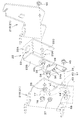
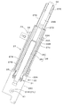
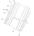
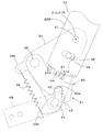
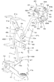
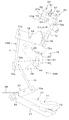
- FIG. 3 is an exploded perspective view of the cockpit. It is a side sectional view of a lower part of a steering shaft. It is an expanded sectional view showing the state where the steering shaft was locked to the adjusted length. It is an expanded sectional view showing the state where the lock of the longitudinal direction of the steering shaft was released. It is a side view of a lock part which shows the state where the steering shaft was locked to the adjusted tilt angle. It is a side view showing the state where the lock of the tilt angle of the steering shaft was released. It is a perspective view of an interlocking mechanism.
- FIG. 5 is a side view of the interlocking mechanism when the operation pedal is operated to a second position. It is a side view of an interlocking mechanism when an operation pedal is further operated from a 2nd position.
- FIG. 8 is a side view of the interlocking mechanism when the operation pedal is operated to a third position. It is a side view of a running vehicle.
- FIG. 17 is a schematic side view showing the traveling vehicle according to the present embodiment.
- the tractor 1 is illustrated as a traveling vehicle.
- the direction of arrow A1 in FIG. 17 (the forward direction of the tractor 1) will be described as forward
- the direction of arrow A2 in FIG. 17 (the backward direction of the tractor 1) will be described as backward. Therefore, the near side in FIG. 17 is the left side, and the far side in FIG. 17 is the right side.
- a horizontal direction orthogonal to the front-rear direction A3 will be described as a vehicle width direction.
- the direction from the center of the tractor 1 in the vehicle width direction to the right or left will be described as the vehicle outward (also referred to as the vehicle width direction outward).
- the outside of the vehicle is a direction that is away from the center of the tractor 1 in the vehicle width direction.
- the direction opposite to the outside of the vehicle will be described as the inside of the vehicle (also referred to as the inside of the vehicle width direction).
- the inside of the vehicle is a direction that is closer to the center of the tractor 1 in the vehicle width direction.
- the tractor 1 has a vehicle body 2 that can travel.
- the vehicle body 2 includes a prime mover E1, a flywheel housing 3, a clutch housing 4, a transmission case 5, and a front axle frame 6.
- the prime mover E1 is a diesel engine.
- the prime mover E ⁇ b> 1 is located at the front of the tractor 1 and is covered by a hood 10.
- the prime mover E1 may be an electric motor or a hybrid type having a diesel engine and an electric motor.
- the flywheel housing 3 is connected to the rear of the prime mover E1 and houses the flywheel.
- the clutch housing 4 is connected to a rear portion of the flywheel housing 3 and houses a clutch that transmits the power of the prime mover E1 transmitted via the flywheel in an intermittent manner.
- the transmission case 5 is connected to a rear portion of the clutch housing 4 and houses a transmission (transmission) that changes the power transmitted through the clutch.
- the transmission has a forward / reverse switching mechanism for switching the power transmitted by the transmission forward or reverse to switch to forward or reverse output.
- the front axle frame 6 is fixed to the prime mover E1 and protrudes forward from the prime mover E1.
- the front axle frame 6 supports a front axle case 15.
- the tractor 1 has a traveling device 8 that supports the vehicle body 2 so as to be able to travel.
- the traveling device 8 is a wheel-type traveling device having a plurality of front wheels 11L and 11R provided at a front portion of the vehicle body 2 and a plurality of rear wheels 12L and 12R provided at a rear portion of the vehicle body 2.
- the plurality of front wheels include a left front wheel 11L supported on the left side of the front axle case 15 and a right front wheel 11R supported on the right side of the front axle case 15.
- the plurality of rear wheels include a left rear wheel 12L supported on the left side of the transmission case 5 and a right rear wheel 12R supported on the right side of the transmission case 5.
- the traveling device 8 may be a semi-crawler traveling device (a traveling device having a front wheel and a crawler traveling mechanism employed in place of the rear wheel).
- the left front wheel 11L and the right front wheel 11R are steered wheels that can be steered by movement of a cylinder rod of a steering cylinder 16 provided in a front portion of the front axle case 15.
- the steering cylinder 16 is constituted by a hydraulic cylinder.
- the steering device that steers the vehicle body 2 may be a hydraulic power steering device including the steering cylinder 16 described above, or may steer the front wheels 11L and 11R using the power of an electric motor. It may be an electric power steering device or a steering device that transmits the operating force of the steering handle 19 to the front wheels 11L and 11R by a mechanical power transmission mechanism.
- a driver's seat 13 on which a driver (operator) sits is mounted on a rear portion of the vehicle body 2.
- a steering device 14 that steers the vehicle body 2 is provided in front of the driver's seat 13.
- the steering device 14 is provided on a back surface of a support member 30 erected on the vehicle body 2.
- the support member 30 is disposed at the rear of the bonnet 10 and separates the inside of the bonnet 10 from a region where the driver's seat 13 and the control device 14 are disposed.
- the steering device 14 includes a steering handle 19 that steers the vehicle body 2 (the front wheels 11L and 11R), a support frame 17 that supports the steering handle 19, and a steering cover 18 that covers the steering platform.
- the support frame 17 includes a fixed bracket 21 fixed to the back surface of the support member 30 and a fixed bracket 21 around an axis (tilt axis) X1 extending in the vehicle width direction.
- a movable bracket 22 supported rotatably (tilted).
- the fixed bracket 21 includes a first bracket 21L and a second bracket 21R.
- the first bracket 21L and the second bracket 21R are formed of a plate material, and are arranged at intervals in the vehicle width direction.
- the first bracket 21 ⁇ / b> L is formed to be long in the up-down direction, and is fixed to the back surface of the support member 30 and the lower end is fixed to the lower portion of the support member 30.
- the second bracket 21R is arranged on the upper right side of the first bracket 21L.
- the second bracket 21R is fixed to the back surface of the support member 30.
- the movable bracket 22 is formed of a plate material, and has an upper wall 22A, a first side wall 22B fixed to a left end of the upper wall 22A, and a lower part from a right end of the upper wall 22A. And a second side wall 22C extending to the side.
- a circular opening 23 is formed in the upper wall 22A.
- the opening 23 is formed through the upper wall 22A.
- the movable bracket 22 is provided with a steering post 27.
- the steering post 27 supports a steering shaft 26.
- the steering handle 19 is attached to the upper part of the steering shaft 26 (see FIG. 17).
- the steering post 27 has an outer cylinder 27A, an inner cylinder 27B, and a support cylinder 27C.
- the lower end of the outer cylinder 27A is fixed to the upper wall 22A.
- the outer cylinder 27A is provided so as to surround the opening 23.
- the inner cylinder 27B is inserted into the outer cylinder 27A.
- the inner cylinder 27B is movable in the axial direction with respect to the outer cylinder 27A, and is not rotatable around the axis by key connection or the like.
- a ring disk-shaped end plate 27D is fixed to the upper end of the inner cylinder 27B.
- the lower end of the support cylinder 27C is fixed to the end plate 27D.
- a support bush 27E is inserted into the upper part of the support cylinder 27C.
- the steering shaft 26 has a first shaft 28 and a second shaft 29.
- the first shaft 28 is disposed in the inner cylinder 27B and has a lower portion protruding below the upper wall 22A through the opening 23.
- a lower portion of the first shaft 28 is supported by a bearing member 31 fixed to the upper wall portion 22A so as to be rotatable around the axis.
- the bearing member 31 has an upper portion fixed to the inner peripheral surface of the opening 23 and protrudes downward from the upper wall portion 22A.
- the lower portion of the first shaft 29 protrudes downward from the bearing member 31, and a steering valve is connected to this protruding portion via a coupling, for example.
- the steering valve is a rotary valve that is operated by the steering shaft 26 and outputs hydraulic oil for operating the steering cylinder 16. Note that the steering valve does not have to be directly connected to the first shaft 29.
- the steering valve may be arranged below the steering device 14, and the first shaft 29 and the steering valve may be linked to each other by a power transmission mechanism having a universal joint.
- the second shaft 29 has a lower large-diameter portion 29A and an upper small-diameter portion 29B.
- the large diameter portion 29A is arranged in the inner cylinder 27B, and is spline-coupled to the first shaft 28. Therefore, the second shaft 29 is movable in the axial direction with respect to the first shaft 28 and is integrally rotatable around the axial center. That is, the steering shaft 26 can be extended and contracted in the axial direction, and the length can be adjusted by extending and contracting the steering shaft 26.
- the upper end of the large diameter portion 29A is in contact with the end plate 27D.
- the small diameter portion 29B protrudes upward from the end plate 27D and passes through the support bush 27E.
- the small diameter portion 29B is supported by the support bush 27E so as to be rotatable around the axis.
- the steering handle 19 is mounted above the small diameter portion 29B.
- the tractor 1 has a telescopic lock section 20 for locking the steering shaft 26 to the adjusted length.
- the telescopic lock unit 20 has a lock member (referred to as a first lock member) 33 that restricts expansion and contraction of the steering shaft 26.
- the first lock member 33 is provided above the outer cylinder 27A.
- the first lock member 33 is formed in a tubular shape, and is fitted to the outside of the inner cylinder 27B so as to be relatively movable (movable up and down) in the axial direction.
- the upper part 33A of the first lock member 33 is formed in a cylindrical shape.
- the first lock member 33 has a tapered portion 33B at a lower portion.
- the tapered portion 33B is formed on a tapered surface whose diameter gradually decreases (the diameter gradually decreases) as the outer surface shape goes downward, and is formed in a conical outer shape.
- the telescopic lock portion 20 has an insertion portion 27a with which the tapered portion 33B of the first lock member 33 engages.
- the insertion portion 27a is formed on an upper portion of the outer cylinder 27A.
- the insertion portion 27a is formed in a tapered surface whose diameter gradually increases (the diameter gradually increases) as the inner surface shape moves upward.
- FIG. 6 shows a state where the first lock member 33 is located at the lock position. In this state, the tapered portion 33B of the first lock member 33 is pushed between the insertion portion 27a and the inner cylinder 27B. Therefore, in the lock position, the first lock member 33 restricts the relative movement between the outer cylinder 27A and the inner cylinder 27B by the wedge action. Thereby, the steering shaft 26 can be locked at the adjusted length.
- FIG. 7 shows the highest position where the first lock member 33 is moved to the uppermost position from the lock position.
- the first lock member 33 is displaced upward from the lock position with respect to the insertion portion 27a and the inner cylinder 27B. Therefore, at the highest position, a gap is formed between the insertion portion 27a and the tapered portion 33B, the wedge action is released, and the relative movement between the outer cylinder 27A and the inner cylinder 27B is allowed. Accordingly, the steering shaft 26 can be extended and contracted, and the length of the steering shaft 26 can be adjusted.
- the first side wall 22B is pivotally supported by the first bracket 21L via a first tilt shaft (tilt shaft) 25L. More specifically, a vertically intermediate portion of the first side wall portion 22B is rotatably supported around the axis (tilt axis X1) of the first tilt shaft 25L on the rear side of the upper portion of the first bracket 21L. .
- the second side wall 22C is pivotally supported by the first bracket 21L via a second tilt shaft (tilt shaft) 25R. Specifically, the second tilt shaft 25R passes through the lower part of the second side wall 22C and the rear part of the lower part of the second bracket 21R.
- the second tilt shaft 25R is prevented from coming off by screwing the nut 66 (fitting the screws).
- the lower portion of the second bracket 21R is supported by the second bracket 21R so as to be rotatable around the axis (tilt axis X1) of the second tilt shaft 25R.
- the movable bracket 22 is rotatably supported on the fixed bracket 21 around the tilt axis X1 by the first tilt shaft 25L and the second tilt shaft 25R.
- the steering shaft 26 can be tilted (tilted) around the tilt axis X1.
- the first tilt axis 25L and the second tilt axis 25R (tilt axis) are the centers of the tilt operation (tilt operation) of the steering shaft 26, and the steering shaft 26 adjusts the tilt angle about the tilt axis X1 (tilt adjustment). ) Is possible.
- a support plate 34 is provided inside (the right side) of the first side wall 22 ⁇ / b> B.
- the first tilt shaft 21L is fixed to an upper portion of the support plate 34.
- the first tilt shaft 21L penetrates the first side wall 22B and the first bracket 21L.
- the first tilt shaft 21L is prevented from being pulled out by screwing the nut 35 into place.
- a support shaft 36 is fixed to an intermediate portion in the vertical direction of the support plate 34 and to the front portion.
- the support shaft 36 is inserted through the first bracket 21L.
- the support shaft 36 is prevented from being pulled out by screwing a nut 37.
- the support plate 34 is fixedly attached to the first bracket 21L by a first tilt shaft 21L and a nut 35 and a support shaft 36 and a nut 37.
- the tractor 1 has a tilt lock portion 61 that locks the steering shaft 26 at the adjusted tilt angle.
- the tilt lock portion 61 includes the first meshing portion 24, a lock member (referred to as a second lock member) 40, and a locking member 43.
- the first engagement portion 24 is formed at the lower end of the first side wall 22B.
- the first engagement portion 24 has a plurality of engagement teeth 24a.
- the plurality of engaging teeth 24a are formed in an arc direction centered on the tilt axis X1.
- a restriction hole 38 is formed between the first tilt shaft 21L and the first meshing portion 24 in the first side wall 22B.
- the restriction hole 38 is formed to penetrate the first side wall portion 22B, and is formed as a circular arc-shaped hole centered on the tilt axis X1.
- a regulating pin 39 is inserted through the regulating hole 38.
- the restriction pin 39 is fixed to the support plate 34. Therefore, the movable bracket 22 can be tilted within a range in which the regulation pin 39 relatively moves from one end to the other end in the regulation hole 38.
- the second lock member 40 is disposed below the first side wall 22B. As shown in FIGS. 3 and 4, the second lock member 40 is disposed between the first bracket 21L and the support plate 34. Further, the second lock member 40 is supported by the support shaft 36 so that the front portion can rotate about an axis extending in the vehicle width direction.
- a second meshing portion 41 having a plurality of engagement teeth 41a is formed.
- the second meshing section 41 can mesh with the first meshing section 24.
- the plurality of engagement teeth 41a are formed in an arc direction centered on the tilt axis X1 in a state where the second meshing portion 41 is meshed with the first meshing portion 24.
- the engagement of the engagement teeth 24a of the first engagement portion 24 with the engagement teeth 41a of the second engagement portion 41 restricts the swing of the movable bracket 22 and locks the steering shaft 26 at the adjusted tilt angle. it can.
- the second lock member 40 swings downward, and the second meshing portion 41 separates from the first meshing portion 24, whereby swinging of the movable bracket 22 is allowed, and The tilt angle of the shaft 26 can be adjusted.
- an engagement groove 42 that opens downward is formed in a lower rear portion of the second lock member 40.
- the locking member 43 is disposed below a rear portion of the second lock member 40.
- the locking member 43 is disposed between the first bracket 21L and the support plate 34, and is supported by a pivot 44 having an axis extending in the vehicle width direction at an intermediate portion. .
- the pivot 44 is fixed to a release arm 68 described later, and passes through the first bracket 21L, the locking member 43, and the first side wall 22B.
- the pivot shaft 44 is prevented from being pulled out by screwing a nut 45.
- the pivot 44 is rotatable with respect to the first bracket 21L and the first side wall 22B.
- the locking member 43 is fitted to the pivot 44 so as to be integrally rotatable. Therefore, the locking member 43 and the release arm 68 rotate integrally with the pivot 44.
- the locking member 43 has an engaging portion 43a provided on the upper side and a spring hooking portion 43b provided on the lower side.
- the engaging portion 43a can engage with the engaging groove 42.
- One end of a spring member 46 composed of a tension coil spring is hooked on the spring hook 43b.
- the other end of the spring member 46 is hooked on a spring hook 34 a provided at the front of the support plate 34.
- the spring member 46 urges the locking member 43 in a direction to swing the engaging portion 43a backward.
- FIG. 8 shows a tilt lock state in which the second meshing portion 41 is meshed with the first meshing portion 24.
- the engaging portion 43a is engaged with the lower rear surface of the engaging groove 42.
- the release arm 68 swings downward from this state, the locking member 43 swings against the urging force of the spring member 46 so that the engaging portion 43a moves forward as shown in FIG. I do.
- the engagement portion 43a is disengaged from the lower portion of the rear surface of the engagement groove 42 and moves toward the depth of the engagement groove 42.
- the second lock member 40 swings downward, the second meshing portion 41 is disengaged from the first meshing portion 24, and the tilt angle of the steering shaft 26 can be adjusted.
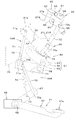
- an operation pedal (operation member) 47 is provided on the side of the first bracket 21L. Specifically, the operation pedal 47 is disposed on the back surface of the support member 30 and on the side (left side) below the first bracket 21L.
- the operation pedal 47 is interlocked with the tilt lock unit 61 and the telescopic lock unit 20 by the interlocking mechanism 49, and performs an unlocking operation by the tilt lock unit 61 and the telescopic lock unit 20. . That is, the unlocking operation by the tilt lock unit 61 and the telescopic lock unit 20 can be performed by the single operation pedal 47.
- the operation pedal 47 is supported by a bracket member (referred to as a pedal bracket) 48.
- the pedal bracket 48 is arranged on the lower left side of the first bracket 21L, and is fixed to the back surface of the support member 30.
- a rotary shaft 62 having an axis extending in the vehicle width direction is provided on the pedal bracket 48 so as to be rotatable around the axis.
- the front portion of the operation pedal 47 is fixed to the rotation shaft 62 so as to be integrally rotatable.
- the operation pedal 47 has a step portion 47a at the rear portion for the operator to step on.
- the interlocking mechanism 49 includes a first interlocking section 49A for interlocking the operation member 47 and the tilt lock section 61, and a second interlocking section for interlocking the first interlocking section 49A and the telescopic lock section 20. 49B.
- the first interlocking section 49A has an interlocking arm 67, an interlocking link 70, and a release arm 68.
- the interlocking arm 67 has one end (front portion) connected to the rotation shaft 62, and is supported by the pedal bracket 48 via the rotation shaft 62 so as to be vertically swingable. I have. Therefore, the interlocking arm 67 swings up and down integrally with the operation pedal 47.
- a hook hole 73 is formed in the middle of the interlocking arm 67.
- One end of a return spring 74 constituted by a tension coil spring is hooked in the hook hole 73.
- the other end of the return spring 74 is hooked on a bracket member 75 fixed to the back surface of the support member 30.
- a hook hole 76 is formed in the lower portion of the bracket member 75, and the other end of the return spring 74 is hooked in the hook hole 76. The urging force of the return spring 74 urges the interlock arm 67 and the operation pedal 47 to swing upward.
- the interlocking link 70 is formed of a cylindrical bar, and one end (lower end) 70 a is connected to the other end (rear) of the interlock arm 67.
- the one end side portion 70a has an axis extending in the vehicle width direction, and is connected to the interlocking link 70 so as to be rotatable around the axis.
- the other end portion (upper end portion) 70 b of the interlocking link 70 is connected to one end side (front portion) of the release arm 68. More specifically, the other end portion 70b has an axis extending in the vehicle width direction, and is rotatably connected to the release arm 68 about the axis.
- the release arm 68 is disposed above the interlocking arm 67, and the other end (rear part) is pivotally supported by the first bracket 21L via the pivot shaft 44.
- the release arm 68 is pulled down via the interlocking arm 67 and the interlocking link 70 and swings downward.
- the locking member 43 swings in conjunction with the downward swing of the release arm 68, whereby the second meshing portion 41 separates from the first meshing portion 24, and the lock by the tilt lock portion 20 is released. Is done. Therefore, the release arm 68 releases the lock by the tilt lock unit 20 in conjunction with the operation of the operation pedal 47.
- the second interlocking section 49B includes a first relay link 71, a relay arm 69, a second relay link 72, and an operating member 51.
- the relay arm 69 is linked to the release arm 68 by a first relay link 71 and is linked to the operating member 51 by a second relay link.
- the first relay link 71 is formed of a cylindrical bar, and one end portion (lower end portion) 71 a is connected to the release arm 68.
- the one end portion 71 a has an axis extending in the vehicle width direction, and is connected to a front portion of the release arm 68 so as to be rotatable around the axis.
- the one end portion 71a of the first relay link 71 is located forward of the other end portion 70b of the interlocking link 70.
- the other end portion (upper end portion) 71 b of the first relay link 71 is connected to one end side (front portion) of the relay arm 69. More specifically, the other end portion 71b has an axis extending in the vehicle width direction, and is rotatably connected to the relay arm 69 around the axis.
- the relay arm 69 is located above the release arm 68, and the intermediate part is pivotally supported by the first bracket 21L.
- a support cylinder 77 is fixed to an upper portion of the first bracket 21L, and a relay arm 69 is attached to the support cylinder 77 via an attachment member 78.
- the attachment member 78 has an axis X4 extending in the vehicle width direction, and the relay arm 69 is rotatably supported around the axis of the attachment member 78.
- a play groove (play part) 79 is formed on the other end side (rear part) of the relay arm 69.
- the play groove 79 is formed in an arc-shaped long groove that is long in the vertical direction and is centered on the axis X4 of the mounting member 78.
- the second relay link 72 is formed of a cylindrical bar, and has one end portion (lower end portion) 72 a inserted into the play groove 79.
- the one end side portion 72a has an axis extending in the vehicle width direction, and is rotatable around the axis in the play groove 79, and is movable between one end and the other end in the groove longitudinal direction. It has been inserted.
- the other end portion (upper end portion) 72 b of the second relay link 72 is connected to the operating member 51. More specifically, the other end portion 72b has an axis extending in the vehicle width direction, and is connected to the operating member 51 so as to be rotatable around the axis.
- the operating member 51 supports the first lock member 33 movably up and down.
- the operating member 51 is interlocked with the operation pedal 47 via the first interlocking section 49A, the first relay link 71, the relay arm 69, and the second relay link 72, and is interlocked with the operation of the operation pedal 47.
- the lock by the telescopic lock unit 20 is released.
- the operating member 51 has a first member 52 and a second member 53.
- the first member 52 includes a first portion 52a located to the left of the first lock member 33, a second portion 52b extending rearward and downward from a lower rear end of the first portion 52a, and a rear portion of the second portion 52b. And a third portion 52c extending rightward.
- the first portion 52a has a guide groove 54 at an upper portion and a boss 55 at a lower portion.
- a roller 56 is fitted in the guide groove 54 so as to be rotatable around an axis extending in the vehicle width direction and to be movable in the groove longitudinal direction.
- a pin 57 fixed to the upper portion 33 ⁇ / b> A of the first lock member 33 is inserted through the roller 56.
- the boss 55 is located below the front part of the guide groove 54.
- An insertion hole 58 is formed in the second portion 52b. The other end 72b of the second relay link 72 is inserted into the insertion hole 58.
- the second member 53 includes a first portion 53a located to the right of the first lock member 33 and a second portion 53b extending rearward and downward from a lower rear end of the first portion 53a. And a third portion 53c extending leftward from the rear end of the second portion 53b.
- the first portion 53a has a guide groove 54 at an upper portion and a boss 55 at a lower portion.
- a roller 56 is fitted in the guide groove 54 so as to be rotatable around an axis extending in the vehicle width direction and to be movable in the groove longitudinal direction.
- a pin 57 fixed to the upper part 33 ⁇ / b> A of the first lock member 33 is inserted through the roller 56 so as to be relatively rotatable.
- the boss 55 is located below the front part of the guide groove 54.
- the third portion 52c and the third portion 53c are connected by a fastener 59 having a bolt and a nut.
- the boss 55 is attached to an upper portion of the outer cylinder 27A by an attachment member 60.
- the mounting member 60 has an axis X2 extending in the vehicle width direction, and the operating member 51 is supported by the outer cylinder 27A so as to be vertically swingable around the axis X2 of the mounting member 60.
- the guide groove 54 has a lock portion 54a and a lock release portion 54b.
- the lock portion 54a is formed in an arc shape having a radius R1 about the axis X2 of the mounting member 60
- the lock release portion 54b is formed in an arc shape having a radius R2 about the arc center X3 different from the axis X2. Is formed.
- the arc center X3 is a line extending in the vehicle width direction, and is located behind and below the axis X2.
- FIG. 13 shows a state where the first lock member 33 is located at the lock position.
- the roller 56 is located at the lock portion 54a of the guide groove 54.
- the operating member 51 swings upward around the axis X2 to move the roller 56 at the lower end of the unlocking portion 54b. Push up.
- the first lock member 33 is moved upward.
- the rear portion of the operating member 51 is pushed up, the first lock member 33 moves upward until the roller 56 reaches the rear end of the guide groove 54, as shown in the right end diagram in FIG. Is located at the highest position. While the first lock member 33 is displaced from the lock position to the highest position, the wedge action by the first lock member 33 is released, and the length of the steering shaft 26 can be adjusted.
- FIG. 11 shows a state before the operation pedal 47 is operated, and the operation pedal 47 is located at the first position Y1.
- the tilt lock unit 61 is in the locked state, and the telescopic lock unit 20 is also in the locked state. That is, the steering shaft 26 cannot be tilted and cannot expand and contract.
- the operation pedal 47 is located at the first position Y ⁇ b> 1
- the one end portion 72 a of the second relay link 72 is located at the upper end of the play groove 79.
- the one end side portion 72a of the second relay link 72 is located near (the tilt axis) the first tilt axis 21L and the second tilt axis 21R in a side view.
- the second relay link 72 swings integrally with the steering shaft 26, but the one end portion 72a of the second relay link 72 is moved to the first tilt shaft 21L and the second tilt Since it is located near the shaft 21R, the second relay link 72 is rotated by the relative rotation between the one end portion 72a and the play groove 79 and the relative rotation between the other end portion 72b and the insertion hole 58 and the play. Is allowed to swing integrally with the steering shaft 26.
- the first relay link 71 when the first relay link 71 is pulled down with the downward swing of the release arm 68, the front part of the relay arm 69 swings downward and the rear part swings upward. At this time, the play groove 79 moves upward with respect to the one end side portion 72a. In other words, the one end portion 72a of the second relay link 72 relatively moves within the play groove 79. While the one end portion 72a relatively moves in the play groove 79 to the lower end in the groove longitudinal direction, as shown in FIG. 14, the second relay link 72 is not pushed up. Thus, the operating member 51 does not swing upward and the first lock member 33 does not move upward. That is, the telescopic lock unit 20 maintains the locked state.
- the play groove 79 is a play section that does not link the first interlocking section 49A and the telescopic lock section 20 until a predetermined amount is operated from a position before the operation pedal 47 is operated.
- the operation pedal 47 is operated from the first position Y1 to the second position Y2 shown in FIG. 14, the lock by the tilt lock unit 61 is released but the lock by the telescopic lock unit 20 is not released. That is, the operation pedal 47 is a position operated from the first position Y1, and has a second position Y2 in which the lock by the tilt lock unit 61 is released and the lock by the telescopic lock unit 20 is not released.
- the second position Y2 ranges from a position where the lock is released by the tilt lock unit 61 to a position before the position where the lock is released by the telescopic lock unit 20 in the operation range (operation area) of the operation pedal 47. Between any positions. Next, when the operation pedal 47 is depressed from the second position Y2 shown in FIG. 14, as shown in FIG. 15, the second relay link 72 moves upward in conjunction with the rear portion of the relay arm 69 swinging upward. Moving. More specifically, the lower end of the play groove 79 contacts the one end portion 72a of the second relay link 72 and pushes up the one end portion 72a, so that the second relay link 72 moves upward. Thereby, the operation member 51 swings upward around the mounting member 60, and the first lock member 33 is pushed up. Further, when the operation pedal 47 is depressed, the first lock member 33 is pushed up to the highest position with the upward movement of the second relay link 72 and the upward swing of the operating member 51 as shown in FIG.
- both the tilt adjustment and the length adjustment of the steering shaft 26 can be performed.
- both the release of the lock by the tilt lock unit 61 and the release of the lock by the telescopic lock unit 20 are performed. That is, the operation pedal 47 is a position operated from the second position Y2, and has a third position Y3 at which the lock by the tilt lock unit 61 and the telescopic lock unit 20 is released.
- the third position Y is an arbitrary position in the operation range of the operation range of the operation pedal 47 after the wedge action by the first lock member 33 is released.
- the operation pedal 47 has an operation area in which both the lock by the tilt lock unit 61 and the lock by the telescopic lock unit 20 are released.
- the operation pedal 47 is normally depressed to the maximum.
- the tilt lock unit 61 and the telescopic lock unit 20 can be operated by a single operation pedal 47, and only the tilt adjustment of the steering shaft 26 is performed.
- One of two adjustment patterns can be selected from the case where both the tilt adjustment and the length adjustment are performed. This adjustment pattern can be selected with a single operation pedal 47, which is convenient.
- the operator When the operator gets off the tractor 1, the operator often releases the lock by the tilt lock unit 61 and raises the steering handle 19 to the highest position, so that the space between the driver's seat 13 and the steering handle 19 is widened to get off.
- the operator gets on and off the tractor 1, if the same operator gets on and off, if the length of the steering shaft 26 has already been adjusted, it is not necessary to adjust the length of the steering shaft 26 when getting on and off. You only need to do it. In such a case, it is possible to select a case where only the tilt adjustment can be performed, which is convenient.
- the position where the play groove (play portion) is provided is not limited to the one in the present embodiment, and may be provided in the operating member 51, for example. That is, the guide groove 54 may be formed in an arc shape centering on the axis X2 of the mounting member 60, and the guide groove 54 may be a play portion. In this case, after the roller 56 moves to the rear end of the guide groove 54, the lock by the telescopic lock unit 20 is released by swinging the operating member 51 upward.
- the tractor 1 of the present embodiment has the following effects.
- the tractor (traveling vehicle) 1 is a steering shaft 26 to which a steering handle 19 is attached.
- the steering shaft 26 is capable of adjusting the tilt angle and adjustable in length, and the tilt angle in which the steering shaft 26 is adjusted.
- Operation having a tilt lock section 61 for locking the steering shaft 26, a telescopic lock section 20 for locking the steering shaft 26 to the adjusted length, and an operation area for releasing the lock by the tilt lock section 61 and releasing the lock by the telescopic lock section 20.
- a member 47 is a member 47.
- both the release of the lock by the tilt lock portion 61 and the release of the lock by the telescopic lock portion 20 can be performed by the operation member 47, and the operability of the adjustment of the length of the steering shaft 26 and the adjustment of the tilt angle can be achieved.
- the operation member 47 is a position that has been operated from the first position Y1, which is a position before the operation, and the first position Y1.
- the operation member 47 unlocks the lock by the tilt lock unit 61 and unlocks the lock by the telescopic lock unit 20. It has a second position Y2 where the unlocking is not performed, and a third position Y3 where the lock by the tilt lock unit 61 and the telescopic lock unit 20 is released, the position being operated from the second position Y2.
- an interlocking mechanism 49 that interlocks the operation member 47 with the tilt lock unit 61 and the telescopic lock unit 20 is provided.
- the interlocking mechanism 49 includes a first interlocking unit 49A that interlocks the operation member 47 with the tilt lock unit 61,
- the second interlocking section 49B interlocks the first interlocking section 49A with the telescopic lock section 20, and the first interlocking section 49A interlocks with the telescopic lock section 20 until a predetermined amount is operated from a position before the operation member 47 is operated.
- the first interlocking section 49A has a release arm 68 that unlocks the tilt lock section 61 in conjunction with the operation of the operation member 47, and the second interlocking section 49B interlocks with the operation of the operation member 47.
- the play portion (play groove 79) is provided in the relay arm 69 and is formed by a long groove through which the one end portion 72a of the second relay link 72 is inserted.
- 72a does not move the relay arm 69 and the operating member 51 relative to each other in the long groove, and operates the operating member 47 by a predetermined amount, and then further operates the operating member 47. End in contact with the one end portion 72a is interlocked and the relay arm 69 actuating member 51.
- a structure in which the tilt adjustment and the length adjustment of the steering shaft 26 can be performed with one operation member 47 can be further simplified.
- a tilt shaft (first tilt shaft 21L, second tilt shaft 21R), which is the center of the tilting operation of the steering shaft 26, is provided, so that the tilt angle of the steering shaft 26 can be adjusted and the length can be adjusted.
- the center of the one end portion 72a of the second relay link 72 coincides with the axis of the tilt shaft (tilt axis X1).
Abstract
La présente invention améliore l'aptitude au fonctionnement lors de l'ajustement de l'angle d'inclinaison et de la longueur d'un arbre de direction (26). A cet effet, l'invention porte sur un véhicule de déplacement, lequel véhicule comprend : un arbre de direction (26) ayant un angle d'inclinaison ajustable et une longueur ajustable, et auquel un volant de direction (19) est attachée ; une partie de verrouillage d'inclinaison (61) qui verrouille l'arbre de direction (26) dans un angle d'inclinaison ajusté ; une partie de verrouillage télescopique (20) qui verrouille l'arbre de direction (26) à une longueur ajustée ; et un élément fonctionnel (47) ayant une zone de fonctionnement dans laquelle tout à la fois une libération de verrouillage par la partie de verrouillage d'inclinaison (61) et une libération de verrouillage par la partie de verrouillage télescopique (20) sont effectuées.
Priority Applications (3)
| Application Number | Priority Date | Filing Date | Title |
|---|---|---|---|
| EP19855220.0A EP3845434A4 (fr) | 2018-08-31 | 2019-08-26 | Véhicule de déplacement |
| CN201980056726.8A CN112638744B (zh) | 2018-08-31 | 2019-08-26 | 行驶车辆 |
| US17/131,883 US11383753B2 (en) | 2018-08-31 | 2020-12-23 | Traveling vehicle |
Applications Claiming Priority (2)
| Application Number | Priority Date | Filing Date | Title |
|---|---|---|---|
| JP2018-163388 | 2018-08-31 | ||
| JP2018163388A JP7004417B2 (ja) | 2018-08-31 | 2018-08-31 | 走行車両 |
Related Child Applications (1)
| Application Number | Title | Priority Date | Filing Date |
|---|---|---|---|
| US17/131,883 Continuation US11383753B2 (en) | 2018-08-31 | 2020-12-23 | Traveling vehicle |
Publications (1)
| Publication Number | Publication Date |
|---|---|
| WO2020045346A1 true WO2020045346A1 (fr) | 2020-03-05 |
Family
ID=69645160
Family Applications (1)
| Application Number | Title | Priority Date | Filing Date |
|---|---|---|---|
| PCT/JP2019/033319 WO2020045346A1 (fr) | 2018-08-31 | 2019-08-26 | Véhicule de déplacement |
Country Status (5)
| Country | Link |
|---|---|
| US (1) | US11383753B2 (fr) |
| EP (1) | EP3845434A4 (fr) |
| JP (1) | JP7004417B2 (fr) |
| CN (1) | CN112638744B (fr) |
| WO (1) | WO2020045346A1 (fr) |
Cited By (1)
| Publication number | Priority date | Publication date | Assignee | Title |
|---|---|---|---|---|
| CN114435459A (zh) * | 2020-11-03 | 2022-05-06 | 丰田自动车株式会社 | 车辆用转向操作装置、车辆用转舵系统 |
Families Citing this family (1)
| Publication number | Priority date | Publication date | Assignee | Title |
|---|---|---|---|---|
| US11498604B2 (en) * | 2020-03-10 | 2022-11-15 | Kubota Corporation | Work vehicle |
Citations (7)
| Publication number | Priority date | Publication date | Assignee | Title |
|---|---|---|---|---|
| JP2002019621A (ja) * | 2000-07-07 | 2002-01-23 | Yamada Seisakusho Co Ltd | ステアリング位置調整装置 |
| JP2004299610A (ja) * | 2003-03-31 | 2004-10-28 | Calsonic Kansei Corp | 車両用ステアリング装置 |
| JP2005001517A (ja) * | 2003-06-12 | 2005-01-06 | Nsk Ltd | ステアリング装置 |
| JP2005138825A (ja) * | 2003-10-14 | 2005-06-02 | Nsk Ltd | ステアリングコラム装置 |
| JP2008068793A (ja) * | 2006-09-15 | 2008-03-27 | Jtekt Corp | ロック装置及びこれを備えた操舵装置 |
| JP2016185723A (ja) * | 2015-03-27 | 2016-10-27 | 富士機工株式会社 | ステアリングコラム装置 |
| JP2017087953A (ja) | 2015-11-10 | 2017-05-25 | ヤンマー株式会社 | 作業車両 |
Family Cites Families (20)
| Publication number | Priority date | Publication date | Assignee | Title |
|---|---|---|---|---|
| US2903904A (en) * | 1958-03-19 | 1959-09-15 | Gen Motors Corp | Adjustable steering column and shaft |
| US5439252A (en) * | 1993-04-22 | 1995-08-08 | Trw Inc. | Dual pivot steering column |
| US6460427B1 (en) * | 2002-01-28 | 2002-10-08 | Ford Global Technologies, Inc. | Adjustment linkage for tilting and telescoping a steering column assembly |
| JP2005280543A (ja) * | 2004-03-30 | 2005-10-13 | Fuji Kiko Co Ltd | 車両用ステアリング装置 |
| US7484430B2 (en) * | 2004-07-27 | 2009-02-03 | Delphi Technologies, Inc. | Telescope feature used for energy absorption |
| US7422238B2 (en) * | 2005-01-11 | 2008-09-09 | Delphi Technologies, Inc. | Rake design for steering column rake adjustment |
| US20070068310A1 (en) * | 2005-09-01 | 2007-03-29 | Koji Arihara | Steering column device for steering wheel of vehicle |
| US7584996B2 (en) * | 2006-05-25 | 2009-09-08 | Trw Automotive U.S. Llc | Steering column memory mechanism |
| ITBO20060777A1 (it) * | 2006-11-14 | 2008-05-15 | A M A S P A | Colonna di sterzo |
| JP2008143324A (ja) * | 2006-12-08 | 2008-06-26 | Yanmar Co Ltd | チルト式ハンドル装置 |
| EP2212181B1 (fr) * | 2007-11-13 | 2012-07-18 | Renault Trucks | Dispositif pour régler la position d'une colonne de direction |
| JP5418831B2 (ja) * | 2009-10-22 | 2014-02-19 | 株式会社ジェイテクト | 位置調整式操舵装置 |
| JP2012046111A (ja) * | 2010-08-27 | 2012-03-08 | Jtekt Corp | 位置調整式操舵装置 |
| US8523227B2 (en) * | 2010-12-13 | 2013-09-03 | Caterpillar Inc. | Single point friction lock for tilt and telescope adjustment of steering columns |
| CA3188304A1 (fr) * | 2012-10-11 | 2014-04-17 | Polaris Industries Inc. | Vehicule biplace cote a cote |
| US9623895B2 (en) * | 2014-04-11 | 2017-04-18 | Nsk Ltd. | Steering device |
| JP2016185125A (ja) * | 2015-03-27 | 2016-10-27 | ヤンマー株式会社 | 作業車両 |
| US9840269B2 (en) * | 2015-07-08 | 2017-12-12 | Jtekt Corporation | Steering system |
| CN205971452U (zh) * | 2015-11-17 | 2017-02-22 | 江苏华骋科技有限公司 | 一种脚踏式可倾方向柱失效保险机构 |
| JP6884689B2 (ja) * | 2017-12-27 | 2021-06-09 | 株式会社クボタ | 走行車両 |
-
2018
- 2018-08-31 JP JP2018163388A patent/JP7004417B2/ja active Active
-
2019
- 2019-08-26 CN CN201980056726.8A patent/CN112638744B/zh active Active
- 2019-08-26 EP EP19855220.0A patent/EP3845434A4/fr active Pending
- 2019-08-26 WO PCT/JP2019/033319 patent/WO2020045346A1/fr unknown
-
2020
- 2020-12-23 US US17/131,883 patent/US11383753B2/en active Active
Patent Citations (7)
| Publication number | Priority date | Publication date | Assignee | Title |
|---|---|---|---|---|
| JP2002019621A (ja) * | 2000-07-07 | 2002-01-23 | Yamada Seisakusho Co Ltd | ステアリング位置調整装置 |
| JP2004299610A (ja) * | 2003-03-31 | 2004-10-28 | Calsonic Kansei Corp | 車両用ステアリング装置 |
| JP2005001517A (ja) * | 2003-06-12 | 2005-01-06 | Nsk Ltd | ステアリング装置 |
| JP2005138825A (ja) * | 2003-10-14 | 2005-06-02 | Nsk Ltd | ステアリングコラム装置 |
| JP2008068793A (ja) * | 2006-09-15 | 2008-03-27 | Jtekt Corp | ロック装置及びこれを備えた操舵装置 |
| JP2016185723A (ja) * | 2015-03-27 | 2016-10-27 | 富士機工株式会社 | ステアリングコラム装置 |
| JP2017087953A (ja) | 2015-11-10 | 2017-05-25 | ヤンマー株式会社 | 作業車両 |
Non-Patent Citations (1)
| Title |
|---|
| See also references of EP3845434A4 |
Cited By (1)
| Publication number | Priority date | Publication date | Assignee | Title |
|---|---|---|---|---|
| CN114435459A (zh) * | 2020-11-03 | 2022-05-06 | 丰田自动车株式会社 | 车辆用转向操作装置、车辆用转舵系统 |
Also Published As
| Publication number | Publication date |
|---|---|
| CN112638744A (zh) | 2021-04-09 |
| CN112638744B (zh) | 2023-03-07 |
| EP3845434A1 (fr) | 2021-07-07 |
| JP2020032968A (ja) | 2020-03-05 |
| US20210107554A1 (en) | 2021-04-15 |
| JP7004417B2 (ja) | 2022-01-21 |
| US11383753B2 (en) | 2022-07-12 |
| EP3845434A4 (fr) | 2022-05-18 |
Similar Documents
| Publication | Publication Date | Title |
|---|---|---|
| WO2012096090A1 (fr) | Dispositif de direction pour engin de chantier | |
| WO2020045346A1 (fr) | Véhicule de déplacement | |
| JP5860380B2 (ja) | 変速操作機構及び作業車両 | |
| JP4504299B2 (ja) | 建設機械の操作手段のロック構造 | |
| JP5486517B2 (ja) | 建設機械のステアリング装置 | |
| JPH0327024Y2 (fr) | ||
| JP5044493B2 (ja) | 作業車の作業部操作装置 | |
| JP6884689B2 (ja) | 走行車両 | |
| JP5602644B2 (ja) | 建設機械のステアリング装置 | |
| US11447194B2 (en) | Operating mechanism of work vehicle | |
| JP2007092284A (ja) | 作業車 | |
| JP6725804B2 (ja) | 作業車両 | |
| JP6900309B2 (ja) | 走行車両 | |
| JP5722723B2 (ja) | 作業車の油圧装置 | |
| JP6785151B2 (ja) | 作業車両 | |
| JP2527408Y2 (ja) | 作業者の操作連係構造 | |
| JPH04342663A (ja) | 車両のハンドルチルト装置 | |
| JP4948341B2 (ja) | 作業機操作レバー | |
| JP2001322467A (ja) | 建設機械の運転室 | |
| JPH034005Y2 (fr) | ||
| JP2021127064A (ja) | 位置制御機構及び車両 | |
| JP4537939B2 (ja) | トラクタの操作装置 | |
| JP2017115901A (ja) | 作業車両 | |
| JP2008006980A (ja) | 作業車両 | |
| JP2006224915A (ja) | 作業車両の操向装置 |
Legal Events
| Date | Code | Title | Description |
|---|---|---|---|
| 121 | Ep: the epo has been informed by wipo that ep was designated in this application |
Ref document number: 19855220 Country of ref document: EP Kind code of ref document: A1 |
|
| NENP | Non-entry into the national phase |
Ref country code: DE |
|
| ENP | Entry into the national phase |
Ref document number: 2019855220 Country of ref document: EP Effective date: 20210331 |